EP2862502A1 - Endoskop - Google Patents
Endoskop Download PDFInfo
- Publication number
- EP2862502A1 EP2862502A1 EP20140187272 EP14187272A EP2862502A1 EP 2862502 A1 EP2862502 A1 EP 2862502A1 EP 20140187272 EP20140187272 EP 20140187272 EP 14187272 A EP14187272 A EP 14187272A EP 2862502 A1 EP2862502 A1 EP 2862502A1
- Authority
- EP
- European Patent Office
- Prior art keywords
- endoscope
- main body
- ring
- endoscope according
- camera connection
- Prior art date
- Legal status (The legal status is an assumption and is not a legal conclusion. Google has not performed a legal analysis and makes no representation as to the accuracy of the status listed.)
- Granted
Links
Images
Classifications
-
- A—HUMAN NECESSITIES
- A61—MEDICAL OR VETERINARY SCIENCE; HYGIENE
- A61B—DIAGNOSIS; SURGERY; IDENTIFICATION
- A61B1/00—Instruments for performing medical examinations of the interior of cavities or tubes of the body by visual or photographical inspection, e.g. endoscopes; Illuminating arrangements therefor
- A61B1/04—Instruments for performing medical examinations of the interior of cavities or tubes of the body by visual or photographical inspection, e.g. endoscopes; Illuminating arrangements therefor combined with photographic or television appliances
- A61B1/042—Instruments for performing medical examinations of the interior of cavities or tubes of the body by visual or photographical inspection, e.g. endoscopes; Illuminating arrangements therefor combined with photographic or television appliances characterised by a proximal camera, e.g. a CCD camera
-
- A—HUMAN NECESSITIES
- A61—MEDICAL OR VETERINARY SCIENCE; HYGIENE
- A61B—DIAGNOSIS; SURGERY; IDENTIFICATION
- A61B1/00—Instruments for performing medical examinations of the interior of cavities or tubes of the body by visual or photographical inspection, e.g. endoscopes; Illuminating arrangements therefor
- A61B1/00112—Connection or coupling means
- A61B1/00121—Connectors, fasteners and adapters, e.g. on the endoscope handle
- A61B1/00124—Connectors, fasteners and adapters, e.g. on the endoscope handle electrical, e.g. electrical plug-and-socket connection
-
- A—HUMAN NECESSITIES
- A61—MEDICAL OR VETERINARY SCIENCE; HYGIENE
- A61B—DIAGNOSIS; SURGERY; IDENTIFICATION
- A61B1/00—Instruments for performing medical examinations of the interior of cavities or tubes of the body by visual or photographical inspection, e.g. endoscopes; Illuminating arrangements therefor
- A61B1/00112—Connection or coupling means
- A61B1/00121—Connectors, fasteners and adapters, e.g. on the endoscope handle
- A61B1/00126—Connectors, fasteners and adapters, e.g. on the endoscope handle optical, e.g. for light supply cables
-
- A—HUMAN NECESSITIES
- A61—MEDICAL OR VETERINARY SCIENCE; HYGIENE
- A61B—DIAGNOSIS; SURGERY; IDENTIFICATION
- A61B1/00—Instruments for performing medical examinations of the interior of cavities or tubes of the body by visual or photographical inspection, e.g. endoscopes; Illuminating arrangements therefor
- A61B1/00163—Optical arrangements
-
- A—HUMAN NECESSITIES
- A61—MEDICAL OR VETERINARY SCIENCE; HYGIENE
- A61B—DIAGNOSIS; SURGERY; IDENTIFICATION
- A61B1/00—Instruments for performing medical examinations of the interior of cavities or tubes of the body by visual or photographical inspection, e.g. endoscopes; Illuminating arrangements therefor
- A61B1/00163—Optical arrangements
- A61B1/00195—Optical arrangements with eyepieces
Definitions
- the present invention relates to an endoscope having an endoscope shaft and a main body connected to the endoscope shaft, which has a camera terminal to which an optical pickup device is mechanically fixable, wherein the main body is electrically conductive.
- the difficulty can occur in an undesirable manner that generated voltage pulses are transmitted via the endoscope to the endoscope attached to the optical recording device.
- These voltage pulses can lead to a deterioration of the image recording with the image sensor of the optical pickup device. In the case of CCD sensors, this can in particular lead to a noisy image. If CMOS sensors are used, a total picture loss may even occur, in particular due to the digital signal processing.
- the object is achieved in an endoscope mentioned above in that the camera connection has an electrical insulating body, which electrically isolates a camera attachment mechanically fixed optical recording device from the main body.
- the camera connection is thus modified in comparison with known endoscopes such that it has the electrical insulating body.
- already existing endoscopes can be retrofitted in a simple manner such that they have the desired electrical insulation between the optical recording device and the rest of the endoscope as endoscopes according to the invention.
- the camera connection can be arranged at the proximal end of the endoscope.
- the camera terminal may be rotatable relative to the main body.
- the camera connection can be rotatable about a longitudinal axis of the endoscope.
- the camera connection can have a metallic threaded ring with an external thread onto which a corresponding internal thread of the optical recording device can be screwed.
- the metallic threaded ring is preferably arranged on the electrical insulating body so that the metallic threaded ring is electrically insulated from the main body.
- the electrical insulating body may have at least one ring rotatable relative to the main body and the threaded ring may be non-rotatably connected to the at least one ring.
- the rotatability of the camera connection is provided and, on the other hand, the necessary electrical insulation is ensured.
- the electrical insulating body may be formed of a plastic material.
- a plastic material e.g. Polyetheretherketone (PEEK) can be used.
- PEEK Polyetheretherketone
- This plastic is characterized by its high melting temperature and can be repeatedly sterilized or autoclaved.
- the electrical insulating body can also be made of any other suitable dielectric material. It is essential that the material has the desired electrical insulation property.
- the electrical insulating body may be formed in one or more parts.
- the endoscope according to the invention is preferably designed as an optical endoscope which images an object located in front of the endoscope as an image in a focal plane which lies behind the end of the main body facing away from the endoscope shaft (and thus outside the main body).
- an imaging optics can be arranged in the endoscope shaft and in the main body.
- the imaging optics can be arranged in a hermetically sealed interior of the endoscope.
- the endoscope is autoclavable.
- Autoclavable is understood here in particular to mean that the endoscope is exposed to water vapor (in particular saturated water vapor) of at least 100 ° C. or at least 130 ° C. for sterilization for a predetermined period of time (without damaging the endoscope (without in particular that water vapor can penetrate into the endoscope shaft or the interior of the main body).
- the endoscope shaft and the main body are preferably made substantially of a metallic material, such as a metal. Stainless steel, made. Furthermore, the endoscope shaft and the main body are preferably electrically conductive and also electrically conductively connected to one another.
- the endoscope shaft can be designed as a rigid endoscope shaft, as an endoscope shaft with an angled distal end or as a flexible endoscope shaft.
- the endoscope according to the invention can be designed as a medical endoscope or as a technical endoscope.
- the optical recording device may in particular be a digital camera or a digital video camera.
- the optical recording device may, but need not, be part of the endoscope according to the invention.
- the endoscope 1 comprises an endoscope shaft 2 with a distal end 3, which at the same time is the distal end of the endoscope 1.
- the end of the endoscope shaft 2 facing away from the distal end 3 is connected to a main body 4 of the endoscope, which has a camera connection 5 (for example a C-mount connection or a bayonet connection) for an optical recording device 6 (for example a video camera) and an illumination light connection 7 ,
- the optical pickup device 6, which contains, for example, a CMOS sensor 8 is only in the representation of Fig. 2 schematically drawn and may, but need not, be part of the endoscope 1 according to the invention.
- the endoscope shaft 2 and the main body 4 are usually made predominantly of metal (e.g., stainless steel) and thus electrically conductive.
- the camera terminal 5 comprises a mounting ring 9, a metallic threaded ring 10, a fixing ring 11 and an inner ring 12, wherein the mounting ring 9, the fixing ring 11 and the inner ring 12 made of an electrically non-conductive material and thus in particular of an electrically insulating material are formed.
- a plastic material may be used, such as PEEK (polyetheretherketone), which is autoclavable.
- the mounting ring 9, the threaded ring 10 and the fixing ring 11 are rotatably connected to each other and can be rotated together about the longitudinal axis of the endoscope 1 relative to the remaining parts of the main body 4 and relative to the inner ring 11.
- the threaded ring 10 has an external thread 18, onto which a corresponding internal thread of the optical recording device 6 can be screwed.
- the described rotation of mounting ring 9, threaded ring 10 and fixing ring 11 provided, so that a rotation of these three rings 9 to 11 screwing the optical pickup device 6 can be realized on the camera terminal 5.
- the mounting ring 9 recessed grips 13, which are arranged side by side in the circumferential direction.
- the mounting ring 9, the fixing ring 11 and the inner ring 12 are formed of an electrically insulating material, they together form an electrical insulator 14, which ensures that the optical receptacle 6 mechanically connected to the camera terminal 5 is electrically isolated from the main body 4. There is no electrical connection between the main body 4 and the optical pickup device 6 in the area of the camera connection 5.
- the formation of the threaded ring 10 as a metallic threaded ring 10 leads to the advantage that on the one hand a good mechanical connection with the optical recording device 6 is possible. On the other hand, a repeated screwing and unscrewing is possible without it would lead to a deterioration of the mechanical connection.
- the metallic threaded ring 10 is in contact only with the mounting ring 9 and the fixing ring 11, which are both electrically non-conductive, thus the metallic threaded ring 10 is also electrically insulated from the main body 4 by the electrical insulating body 14.
- Fig. 3 can be seen, the threaded ring 10 on its inside a plurality of inwardly projecting lugs 15 which are in positive engagement with corresponding groove-shaped recesses 16 on the outside of a support portion 17 of the mounting ring 9, so that a rotationally fixed connection between the threaded ring 10 and the mounting ring 9 is present.
- the threaded ring 10 can not be rotated relative to the mounting ring 9 about the longitudinal axis of the endoscope.
- the endoscope 1 is designed to be autoclavable.
- a hermetically sealed interior 20 is provided, which in the proximal end region of the main body 4, as in Fig. 3 is shown bounded by a wall 21 and hermetically sealed at the proximal end by a proximal cover glass 22.
- the interior 20 is connected to an inner tube 23 of the endoscope shaft 2, which extends in an outer tube 19 of the endoscope shaft 2 to the distal end 3.
- the inner tube 23 with a distal cover glass 24 (FIG. Fig. 2 ) hermetically sealed.
- a lens (not shown) for receiving an image of an object located in front of the distal end 3 is arranged in the inner tube 23 behind the distal cover glass 24.
- a known light-guiding system eg rod lenses or reversing systems, which display an input-side image rotated by 180 ° on the output side
- the objective can connect to the objective, which transmits the image up to the proximal end region in the main body 4, on the one hand in the longitudinal direction of the endoscope 1 Optics group 25 (as indicated by the double arrow P1) and on the other hand a fixed optical group 26, which is thus not displaceable in the longitudinal direction of the endoscope 1, is arranged (both optical groups 25, 26 are arranged in the interior space 20).
- a focus on different distances of the image sensors 8 different optical recording device 6 is possible.
- the displacement of the displaceable optical group 25 can be realized in a known manner.
- a focusing ring 27 may be provided with circumferentially spaced grip recesses 28 which carries at least one outer magnet 29.
- Within the interior 20 at least one inner magnet 30 is provided, which is rotatably mounted, so that a rotation of the focusing ring 27 via the magnetic coupling of the two magnets 29, 30 serves to rotate the mounting of the inner magnet 30. This rotation is converted into an axial movement of the displaceable optical group 25.
- no displaceable optics group 25 and possibly no fixed optics group 26 are provided.
- the endoscope as shown in Fig. 2 is indicated, between the inner tube 23 and the outer tube 19 of the endoscope shaft 2 have a channel 31 extending from the illumination light terminal 7 to the distal end 3 and in the optical fibers (not shown) are arranged, which are acted upon by the illumination light terminal 7 with light so that this light emerges at the distal end 3 of the endoscope and can be used to illuminate the object to be received in front of the distal end 3.
Landscapes
- Health & Medical Sciences (AREA)
- Life Sciences & Earth Sciences (AREA)
- Surgery (AREA)
- Nuclear Medicine, Radiotherapy & Molecular Imaging (AREA)
- Biomedical Technology (AREA)
- Optics & Photonics (AREA)
- Pathology (AREA)
- Radiology & Medical Imaging (AREA)
- Biophysics (AREA)
- Engineering & Computer Science (AREA)
- Physics & Mathematics (AREA)
- Heart & Thoracic Surgery (AREA)
- Medical Informatics (AREA)
- Molecular Biology (AREA)
- Animal Behavior & Ethology (AREA)
- General Health & Medical Sciences (AREA)
- Public Health (AREA)
- Veterinary Medicine (AREA)
- Endoscopes (AREA)
Abstract
wobei der Hauptkörper (4) elektrisch leitfähig ist und wobei der Kameraanschluß (5) einen elektrischen Isolierkörper (14) aufweist, der eine am Kameraanschluß (5) mechanisch befestigte optische Aufnahmevorrichtung (6) vom Hauptkörper (4) elektrisch isoliert.
Description
- Die vorliegende Erfindung betrifft ein Endoskop mit einem Endoskopschaft und einem mit dem Endoskopschaft verbundenen Hauptkörper, der einen Kameraanschluß aufweist, an dem eine optische Aufnahmevorrichtung mechanisch befestigbar ist, wobei der Hauptkörper elektrisch leitfähig ist.
- Bei dem Einsatz eines solchen Endoskopes zur optischen Kontrolle bei der Hochfrequenzchirurgie kann in unerwünschter Weise die Schwierigkeit auftreten, dass dabei erzeugte Spannungspulse über das Endoskop bis zu der am Endoskop befestigten optischen Aufnahmevorrichtung übertragen werden. Diese Spannungspulse können zu einer Verschlechterung der Aufnahme des Bildes mit dem Bildsensor der optischen Aufnahmevorrichtung führen. Bei CCD-Sensoren kann dies insbesondere zu einem verrauschten Bild führen. Wenn CMOS-Sensoren eingesetzt werden, kann insbesondere aufgrund der digitalen Signalverarbeitung sogar ein totaler Bildausfall auftreten.
- Erfindungsgemäß ist es daher Aufgabe der vorliegenden Erfindung, das eingangs genannte Endoskop so zu verbessern, dass die genannten Schwierigkeiten möglichst vollständig überwunden werden können.
- Erfindungsgemäß wird die Aufgabe bei einem eingangs genannten Endoskop dadurch gelöst, dass der Kameraanschluß einen elektrischen Isolierkörper aufweist, der eine am Kameraanschluß mechanisch befestigte optische Aufnahmevorrichtung vom Hauptkörper elektrisch isoliert.
- Aufgrund dieser elektrischen Isolierung werden die unerwünschten Spannungspulse vom Endoskop nicht mehr bis zur optischen Aufnahmevorrichtung übertragen, so dass die optische Aufnahmevorrichtung unbeeinflußt von eventuell auftretenden Spannungspulsen in gewünschter Weise das Bild aufnehmen kann.
- Bei dem erfindungsgemäßen Endoskop ist somit im Vergleich zu bekannten Endoskopen der Kameraanschluß so abgewandelt, dass er den elektrischen Isolierkörper aufweist. Damit können in einfacher Art und Weise auch schon vorhandene Endoskope so umgerüstet werden, dass sie als erfindungsgemäße Endoskope die gewünschte elektrische Isolierung zwischen der optischen Aufnahmevorrichtung und dem restlichen Endoskop aufweisen.
- Insbesondere kann der Kameraanschluß am proximalen Ende des Endoskopes angeordnet sein. Des weiteren kann der Kameraanschluß gegenüber dem Hauptkörper drehbar sein. Insbesondere kann der Kameraanschluß um eine Längsachse des Endoskopes drehbar sein.
- Der Kameraanschluß kann einen metallischen Gewindering mit einem Außengewinde aufweisen, auf das ein entsprechendes Innengewinde der optischen Aufnahmevorrichtung aufschraubbar ist.
- Damit wird sichergestellt, dass eine gute Verbindung zwischen dem Kameraanschluß und der optischen Aufnahmevorrichtung vorliegt und dass diese Verbindung mehrfach gelöst und wieder hergestellt werden kann, ohne dass es zu einer Verschlechterung der mechanischen Verbindungseigenschaften kommt.
- Der metallische Gewindering ist bevorzugt so auf dem elektrischen Isolierkörper angeordnet, dass der metallische Gewindering vom Hauptkörper elektrisch isoliert ist.
- Insbesondere kann der elektrische Isolierkörper zumindest einen gegenüber dem Hauptkörper drehbaren Ring aufweisen und kann der Gewindering drehfest mit dem zumindest einen Ring verbunden sein.
- Damit wird einerseits die Drehbarkeit des Kameraanschlusses bereitgestellt und andererseits die notwendige elektrische Isolierung sichergestellt.
- Der elektrische Isolierkörper kann aus einem Kunststoffmaterial gebildet sein. Insbesondere kann z.B. Polyetheretherketon (PEEK) verwendet werden. Dieser Kunststoff zeichnet sich durch seine hohe Schmelztemperatur aus und kann wiederholt sterilisiert bzw. autoklaviert werden.
- Der elektrische Isolierkörper kann natürlich auch aus jedem anderen geeigneten dielektrischen Material hergestellt sein. Wesentlich ist, dass das Material die gewünschte elektrische Isoliereigenschaft aufweist.
- Der elektrische Isolierkörper kann einteilig oder mehrteilig ausgebildet sein.
- Das erfindungsgemäße Endoskop ist bevorzugt als optisches Endoskop ausgebildet, das ein vor dem Endoskopschaft befindliches Objekt als Bild in eine Fokusebene abbildet, die hinter dem vom Endoskopschaft abgewandten Ende des Hauptkörpers (und somit außerhalb des Hauptkörpers) liegt. Dazu kann im Endoskopschaft und im Hauptkörper eine Abbildungsoptik angeordnet sein.
- Insbesondere kann die Abbildungsoptik in einem hermetisch dichten Innenraum des Endoskopes angeordnet sein.
- Bevorzugt ist das Endoskop autoklavierbar. Unter autoklavierbar wird hier insbesondere verstanden, dass das Endoskop während einer vorbestimmten Zeitdauer (beispielsweise mehrere Minuten) Wasserdampf (insbesondere gesättigtem Wasserdampf) von mindestens 100°C bzw. mindestens 130°C zur Sterilisation ausgesetzt wird, ohne dass dabei das Endoskop beschädigt wird (ohne dass insbesondere Wasserdampf in den Endoskopschaft oder den Innenraum des Hauptkörpers eindringen kann).
- Der Endoskopschaft und der Hauptkörper sind bevorzugt im wesentlichen aus einem metallischen Material, wie z.B. Edelstahl, hergestellt. Ferner sind der Endoskopschaft und der Hauptkörper bevorzugt elektrisch leitfähig und auch elektrisch leitfähig miteinander verbunden.
- Der Endoskopschaft kann als starrer Endoskopschaft, als Endoskopschaft mit einem abwinkelbaren distalen Ende oder als flexibler Endoskopschaft ausgebildet sein.
- Das erfindungsgemäße Endoskop kann als medizinisches Endoskop oder als technisches Endoskop ausgebildet sein.
- Die optische Aufnahmevorrichtung kann insbesondere eine digitale Kamera bzw. eine digitale Videokamera sein.
- Die optische Aufnahmevorrichtung kann, muß aber nicht, Bestandteil des erfindungsgemäßen Endoskopes sein.
- Es versteht sich, daß die vorstehend genannten und die nachstehend noch zu erläuternden Merkmale nicht nur in den angegebenen Kombinationen, sondern auch in anderen Kombinationen oder in Alleinstellung einsetzbar sind, ohne den Rahmen der vorliegenden Erfindung zu verlassen.
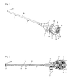
- Nachfolgend wird die Erfindung beispielsweise anhand der beigefügten Zeichnungen, die auch erfindungswesentliche Merkmale offenbaren, noch näher erläutert. Es zeigen:
- Fig. 1
- eine perspektivische Ansicht einer Ausführungsform des erfindungsgemäßen Endoskopes;
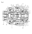
- Fig. 2
- eine Schnittansicht des Endoskopes von
Fig. 1 , und - Fig. 3
- eine vergrößerte Schnittansicht des proximalen Endbereichs des Hauptkörpers 4 des Endoskops von
Fig.1 und 2 . - Bei der in
Fig. 1 und 2 gezeigten Ausführungsform umfaßt das erfindungsgemäße Endoskop 1 einen Endoskopschaft 2 mit einem distalen Ende 3, das gleichzeitig das distale Ende des Endoskops 1 ist. Das dem distalen Ende 3 abgewandte Ende des Endoskopschaftes 2 ist mit einem Hauptkörper 4 des Endoskops verbunden, der einen Kameraanschluß 5 (z.B. ein C-Mount-Anschluß oder ein Bajonettanschluß) für eine optische Aufnahmevorrichtung 6 (beispielsweise eine Videokamera) sowie einen Beleuchtungslichtanschluß 7 aufweist. Die optische Aufnahmevorrichtung 6, die beispielsweise einen CMOS-Sensor 8 enthält, ist lediglich in der Darstellung vonFig. 2 schematisch eingezeichnet und kann, muß aber nicht, Teil des erfindungsgemäßen Endoskops 1 sein. - Der Endoskopschaft 2 und der Hauptkörper 4 sind in der Regel zum überwiegenden Teil aus Metall (z.B. Edelstahl) hergestellt und somit elektrisch leitfähig.
- Wie insbesondere in der vergrößerten Schnittdarstellung von
Fig. 3 ersichtlich ist, umfaßt der Kameraanschluß 5 einen Montagering 9, einen metallischen Gewindering 10, einen Fixierring 11 und einen Innenring 12, wobei der Montagering 9, der Fixierring 11 und der Innenring 12 aus einem elektrisch nicht leitfähigen Material und somit insbesondere aus einem elektrisch isolierenden Material gebildet sind. Als Material kann ein Kunststoffmaterial verwendet werden, wie z.B. PEEK (Polyetheretherketon), das autoklavierbar ist. - Der Montagering 9, der Gewindering 10 und der Fixierring 11 sind drehfest miteinander verbunden und können zusammen um die Längsachse des Endoskopes 1 relativ zu den restlichen Teilen des Hauptkörpers 4 sowie relativ zum Innenring 11 gedreht werden. Der Gewindering 10 weist ein Außengewinde 18 auf, auf das ein entsprechendes Innengewinde der optischen Aufnahmevorrichtung 6 aufgeschraubt werden kann. Um dieses Aufschrauben zu erleichtern, ist die beschriebene Drehbarkeit von Montagering 9, Gewindering 10 und Fixierring 11 vorgesehen, so dass durch Drehung dieser drei Ringe 9 bis 11 ein Aufschrauben der optischen Aufnahmevorrichtung 6 auf den Kameraanschluß 5 verwirklicht werden kann. Um dieses Aufschrauben zu erleichtern, weist der Montagering 9 Griffmulden 13 auf, die in Umfangsrichtung nebeneinanderliegend angeordnet sind.
- Da der Montagering 9, der Fixierring 11 und der Innenring 12 aus einem elektrisch isolierendem Material gebildet sind, bilden sie zusammen einen elektrischen Isolierkörper 14, der dafür sorgt, dass die mit dem Kameraanschluß 5 mechanisch verbundene optische Aufnahmevorrichtung 6 vom Hauptkörper 4 elektrisch isoliert ist. Es liegt im Bereich des Kameraanschlusses 5 keine elektrische Verbindung zwischen dem Hauptkörper 4 und der optischen Aufnahmevorrichtung 6 vor.
- Damit wird der Vorteil erreicht, dass Spannungspulse, die z.B. bei der Hochfrequenzchirurgie oder dem Einsatz eines Elektroskalpells auftreten können und in unerwünschter Weise auf das zur optischen Kontrolle vorgesehene Endoskop 1 und somit auf den Endoskopschaft 2 und von diesem zum Hauptkörper 4 übertragen werden können, nicht zur optischen Aufnahmevorrichtung 6 übertragen werden, da diese aufgrund des elektrischen Isolierkörpers 14 elektrisch vom Hauptkörper 4 isoliert ist. Solche Spannungspulse würden gerade bei CMOS-Sensoren 8 dazu führen, dass ein unerwünschter Bildausfall auftritt. Dies kann bei dem erfindungsgemäßen Endoskop 1 aufgrund des elektrischen Isolierkörpers 14 effektiv verhindert werden.
- Die Ausbildung des Gewinderings 10 als metallischer Gewindering 10 führt zu dem Vorteil, dass einerseits eine gute mechanische Verbindung mit der optischen Aufnahmevorrichtung 6 möglich ist. Andererseits ist ein wiederholtes Auf- und Abschrauben möglich, ohne dass es zu einer Verschlechterung der mechanischen Verbindung kommen würde. Nachdem der metallische Gewindering 10 nur mit dem Montagering 9 und dem Fixierring 11, die beide elektrisch nicht leitend sind, in Kontakt steht, ist somit der metallische Gewindering 10 ebenfalls durch den elektrischen Isolierkörper 14 vom Hauptkörper 4 elektrisch isoliert.
- Wie insbesondere
Fig. 3 zu entnehmen ist, weist der Gewindering 10 auf seiner Innenseite mehrere nach innen vorstehende Nasen 15 auf, die in Formschluß mit entsprechenden nutförmigen Ausnehmungen 16 auf der Außenseite eines Trageabschnitts 17 des Montagerings 9 stehen, so dass eine drehfeste Verbindung zwischen dem Gewindering 10 und dem Montagering 9 vorliegt. Somit kann der Gewindering 10 nicht relativ zum Montagering 9 um die Längsachse des Endoskops gedreht werden. - Das Endoskop 1 ist autoklavierbar ausgebildet. Dazu ist ein hermetisch dichter Innenraum 20 vorgesehen, der im proximalen Endbereich des Hauptkörpers 4, wie in
Fig. 3 gezeigt ist, durch eine Wandung 21 begrenzt ist und am proximalen Ende durch ein proximales Deckglas 22 hermetisch dicht verschlossen ist. Der Innenraum 20 ist mit einem Innenrohr 23 des Endoskopschaftes 2 verbunden, das sich in einem Außenrohr 19 des Endoskopschaftes 2 bis zum distalen Ende 3 erstreckt. Am distalen Ende 3 ist das Innenrohr 23 mit einem distalen Deckglas 24 (Fig. 2 ) hermetisch dicht verschlossen. - Im Innenrohr 23 ist hinter dem distalen Deckglas 24 ein (nicht gezeigtes) Objektiv zur Aufnahme eines Bildes eines vor dem distalen Ende 3 befindlichen Objektes angeordnet. An das Objektiv kann sich ein bekanntes Lichtleitsystem (z.B. Stablinsen oder Umkehrsysteme, die ein eingangsseitiges Bild ausgangsseitig um 180° gedreht abbilden) anschließen, das das Bild bis zu dem proximalen Endbereich im Hauptkörper 4 überträgt, in dem einerseits eine in Längsrichtung des Endoskopes 1 verschiebbare Optikgruppe 25 (wie durch den Doppelpfeil P1 angedeutet ist) und andererseits eine fixe Optikgruppe 26, die somit nicht in Längsrichtung des Endoskopes 1 verschiebbar ist, angeordnet ist (beide Optikgruppen 25, 26 sind im Innenraum 20 angeordnet). Damit ist beispielsweise eine Fokussierung auf unterschiedliche Abstände der Bildsensoren 8 unterschiedlicher optischer Aufnahmevorrichtung 6 möglich. Die Verschiebung der verschiebbaren Optikgruppe 25 kann in bekannter Weise realisiert sein. So kann beispielsweise ein Fokussierring 27 mit in Umfangsrichtung voneinander beabstandeten Griffmulden 28 vorgesehen sein, der zumindest einen Außenmagnet 29 trägt. Innerhalb des Innenraums 20 ist zumindest ein Innenmagnet 30 vorgesehen, der drehbar gelagert ist, so dass eine Drehung des Fokussierringes 27 über die Magnetkopplung der beiden Magnete 29, 30 zu einer Drehung der Lagerung des Innenmagnetes 30 dient. Diese Drehung wird in eine axiale Bewegung der verschiebbaren Optikgruppe 25 umgesetzt.
- In einer alternativen Ausbildung des erfindungsgemäßen Endoskopes 1 ist keine verschiebbare Optikgruppe 25 und ggf. keine fixe Optikgruppe 26 vorgesehen.
- Ferner kann das Endoskop, wie in
Fig. 2 angedeutet ist, zwischen dem Innenrohr 23 und dem Außenrohr 19 des Endoskopschaftes 2 einen Kanal 31 aufweisen, der sich vom Beleuchtungslichtanschluß 7 bis zum distalen Ende 3 erstreckt und in dem Lichtleitfasern (nicht gezeigt) angeordnet sind, die über den Beleuchtungslichtanschluß 7 mit Licht beaufschlagt werden, so dass dieses Licht am distalen Ende 3 des Endoskops austritt und zur Beleuchtung des vor dem distalen Ende 3 aufzunehmenden Objektes verwendet werden kann.
Claims (10)
- Endoskop mit
einem Endoskopschaft (2) und
einem mit dem Endoskopschaft (2) verbundenen Hauptkörper (4), der einen Kameraanschluß (5) aufweist, an dem eine optische Aufnahmevorrichtung (6) mechanisch befestigbar ist,
wobei der Hauptkörper (4) elektrisch leitfähig ist,
dadurch gekennzeichnet, dass der Kameraanschluß (5) einen elektrischen Isolierkörper (14) aufweist, der eine am Kameraanschluß (5) mechanisch befestigte optische Aufnahmevorrichtung (6) vom Hauptkörper (4) elektrisch isoliert. - Endoskop nach Anspruch 1, bei dem der Kameraanschluß (5) am proximalen Ende des Endoskopes (1) angeordnet ist.
- Endoskop nach Anspruch 1 oder 2, dadurch gekennzeichnet, dass der Kameraanschluß (5) gegenüber dem Hauptkörper (4) drehbar ist.
- Endoskop nach einem der obigen Ansprüche, dadurch gekennzeichnet, dass der Kameraanschluß (5) einen metallischen Gewindering (10) mit einem Außengewinde (18) aufweist, auf das ein entsprechendes Innengewinde der optischen Aufnahmevorrichtung (6) aufschraubbar ist.
- Endoskop nach Anspruch 4, dadurch gekennzeichnet, dass der elektrische Isolierkörper (14) zumindest einen gegenüber dem Hauptkörper (4) drehbaren Ring (9, 11) aufweist und der Gewindering (10) drehfest mit dem zumindest einen Ring (9, 11) verbunden ist.
- Endoskop nach einem der obigen Ansprüche, dadurch gekennzeichnet, dass der elektrische Isolierkörper (14) aus einem Kunststoffmaterial gebildet ist.
- Endoskop nach einem der obigen Ansprüche, dadurch gekennzeichnet, dass der elektrische Isolierkörper (14) aus Polyetheretherketon hergestellt ist.
- Endoskop nach einem der obigen Ansprüche, dadurch gekennzeichnet, dass im Endoskopschaft (2) und im Hauptkörper (4) eine Abbildungsoptik (25, 26) angeordnet ist, die ein vor dem Endoskopschaft (2) befindliches Objekt als Bild in eine Fokusebene abbildet, die hinter dem vom Endoskopschaft (2) abgewandten Ende des Hauptkörpers (4) liegt.
- Endoskop nach Anspruch 8, dadurch gekennzeichnet, dass die Abbildungsoptik (25, 26) in einem hermetisch dichten Innenraum (20) des Endoskopes (1) angeordnet ist.
- Endoskop nach einem der obigen Ansprüche, dadurch gekennzeichnet, dass das Endoskop autoklavierbar ist.
Priority Applications (1)
| Application Number | Priority Date | Filing Date | Title |
|---|---|---|---|
| PL14187272T PL2862502T3 (pl) | 2013-10-18 | 2014-10-01 | Endoskop |
Applications Claiming Priority (1)
| Application Number | Priority Date | Filing Date | Title |
|---|---|---|---|
| DE201310221224 DE102013221224A1 (de) | 2013-10-18 | 2013-10-18 | Endoskop |
Publications (2)
| Publication Number | Publication Date |
|---|---|
| EP2862502A1 true EP2862502A1 (de) | 2015-04-22 |
| EP2862502B1 EP2862502B1 (de) | 2021-06-02 |
Family
ID=52000612
Family Applications (1)
| Application Number | Title | Priority Date | Filing Date |
|---|---|---|---|
| EP14187272.1A Active EP2862502B1 (de) | 2013-10-18 | 2014-10-01 | Endoskop |
Country Status (5)
| Country | Link |
|---|---|
| US (1) | US9730574B2 (de) |
| EP (1) | EP2862502B1 (de) |
| DE (1) | DE102013221224A1 (de) |
| ES (1) | ES2882554T3 (de) |
| PL (1) | PL2862502T3 (de) |
Families Citing this family (4)
| Publication number | Priority date | Publication date | Assignee | Title |
|---|---|---|---|---|
| DE102017122225A1 (de) * | 2017-09-26 | 2019-03-28 | Olympus Winter & Ibe Gmbh | Endoskop |
| JP7603680B2 (ja) * | 2019-10-28 | 2024-12-20 | ストライカー コーポレイション | ぜん動内視鏡洗浄のためのシステムおよび方法 |
| CN114569042A (zh) * | 2020-12-02 | 2022-06-03 | 北京威斯顿亚太光电仪器有限公司 | 一种硬性内窥镜系统 |
| US12507873B2 (en) * | 2020-12-23 | 2025-12-30 | Stryker Corporation | Autoclavable endoscope for endoscopic imaging systems |
Citations (3)
| Publication number | Priority date | Publication date | Assignee | Title |
|---|---|---|---|---|
| EP0489240A1 (de) * | 1990-12-03 | 1992-06-10 | Medical Concepts Incorporated | Endoskopischer Adapter mit Zwischenschicht |
| US5609561A (en) * | 1992-06-09 | 1997-03-11 | Olympus Optical Co., Ltd | Electronic type endoscope in which image pickup unit is dismounted to execute disinfection/sterilization processing |
| WO1999039623A1 (de) * | 1998-02-04 | 1999-08-12 | Karl Storz Gmbh & Co. | Endoskop, insbesondere video-endoskop |
Family Cites Families (3)
| Publication number | Priority date | Publication date | Assignee | Title |
|---|---|---|---|---|
| US5599278A (en) * | 1994-03-15 | 1997-02-04 | Erich M. N. Hibbard | Autoclavable rigid endoscope |
| DE102008063619B4 (de) * | 2008-12-18 | 2021-08-26 | Henke-Sass, Wolf Gmbh | Endoskop mit einem Endoskopschaft, in dem an seinem distalen Ende eine Abbildungsoptik angeordnet ist |
| WO2012040529A2 (en) * | 2010-09-24 | 2012-03-29 | Jeffrey Brennan | Imaging systems and methods incorporating non-mechanical scanning beam actuation |
-
2013
- 2013-10-18 DE DE201310221224 patent/DE102013221224A1/de not_active Withdrawn
-
2014
- 2014-10-01 PL PL14187272T patent/PL2862502T3/pl unknown
- 2014-10-01 ES ES14187272T patent/ES2882554T3/es active Active
- 2014-10-01 EP EP14187272.1A patent/EP2862502B1/de active Active
- 2014-10-17 US US14/516,902 patent/US9730574B2/en active Active
Patent Citations (3)
| Publication number | Priority date | Publication date | Assignee | Title |
|---|---|---|---|---|
| EP0489240A1 (de) * | 1990-12-03 | 1992-06-10 | Medical Concepts Incorporated | Endoskopischer Adapter mit Zwischenschicht |
| US5609561A (en) * | 1992-06-09 | 1997-03-11 | Olympus Optical Co., Ltd | Electronic type endoscope in which image pickup unit is dismounted to execute disinfection/sterilization processing |
| WO1999039623A1 (de) * | 1998-02-04 | 1999-08-12 | Karl Storz Gmbh & Co. | Endoskop, insbesondere video-endoskop |
Also Published As
| Publication number | Publication date |
|---|---|
| PL2862502T3 (pl) | 2021-11-08 |
| ES2882554T3 (es) | 2021-12-02 |
| US9730574B2 (en) | 2017-08-15 |
| EP2862502B1 (de) | 2021-06-02 |
| US20150112133A1 (en) | 2015-04-23 |
| DE102013221224A1 (de) | 2015-04-23 |
Similar Documents
| Publication | Publication Date | Title |
|---|---|---|
| DE102009049143B3 (de) | Endoskop | |
| DE69114563T2 (de) | Magnetisch gekoppelter Antrieb. | |
| DE19804234C1 (de) | Endoskop, insbesondere Video-Endoskop | |
| EP2514356B1 (de) | Endoskop mit variabler Blickrichtung | |
| EP2862502B1 (de) | Endoskop | |
| DE102011090132A1 (de) | Videoendoskop und Videoendoskopsystem | |
| EP2198767B1 (de) | Endoskop mit einem Endoskopschaft, in dem an seinem distalen Ende eine Abbildungsoptik angeordnet ist | |
| DE3600283A1 (de) | Endoskop | |
| DE102009017606A1 (de) | Endoskop mit elektrischem Heizsystem | |
| DE102004044119A1 (de) | Videoendoskop mit drehbarer Videokamera | |
| DE19647855A1 (de) | Voll autoklavierbares elektronisches Endoskop | |
| DE102010022430A1 (de) | Sichtfeldvorrichtung für ein Endoskop | |
| DE102011089157A1 (de) | Videoendoskop mit seitlicher Blickrichtung und Verfahren zur Montage eines Videoendoskops | |
| DE102017119691A1 (de) | Endoskop mit einem verdrehbaren, elektrischen Verbindungselement | |
| DE102017103721B4 (de) | Vorrichtung zur Erfassung eines Stereobilds mit einer rotierbaren Blickrichtungseinrichtung | |
| EP3366192A1 (de) | Vorrichtung zum aufnehmen eines bildes eines objektfelds an einem menschlichen oder tierischen körper | |
| DE102019123053A1 (de) | Endoskop mit optischer Filteranordnung und Verwendung | |
| EP2850997A1 (de) | Endoskop oder Exoskop | |
| DE102016212470A1 (de) | Optisches System eines Stereo-Videoendoskops, Stereo-Videoendoskop und Verfahren zum Betreiben eines optischen Systems eines Stereo-Videoendoskops | |
| DE102010047884A1 (de) | Endoskop | |
| EP2818094B1 (de) | Beobachtungsinstrument mit einem symmetrischen bildfeld unter verwendung asymmetrischer bildsensoren | |
| DE102018111645A1 (de) | Bildaufnahmeanordnung, zugehörige Verwendung sowie Verfahren zur Inbetriebnahme einer Bildaufnahmeanordnung | |
| EP3254148A2 (de) | Endoskop | |
| DE102016009476B3 (de) | Endoskopievorrichtung | |
| DE102014107586A1 (de) | 3D-Video-Endoskop |
Legal Events
| Date | Code | Title | Description |
|---|---|---|---|
| PUAI | Public reference made under article 153(3) epc to a published international application that has entered the european phase |
Free format text: ORIGINAL CODE: 0009012 |
|
| 17P | Request for examination filed |
Effective date: 20141001 |
|
| AK | Designated contracting states |
Kind code of ref document: A1 Designated state(s): AL AT BE BG CH CY CZ DE DK EE ES FI FR GB GR HR HU IE IS IT LI LT LU LV MC MK MT NL NO PL PT RO RS SE SI SK SM TR |
|
| AX | Request for extension of the european patent |
Extension state: BA ME |
|
| R17P | Request for examination filed (corrected) |
Effective date: 20151022 |
|
| RBV | Designated contracting states (corrected) |
Designated state(s): AL AT BE BG CH CY CZ DE DK EE ES FI FR GB GR HR HU IE IS IT LI LT LU LV MC MK MT NL NO PL PT RO RS SE SI SK SM TR |
|
| RIN1 | Information on inventor provided before grant (corrected) |
Inventor name: RAPP, STEFAN Inventor name: LAWRENCE, HANNAH Inventor name: HAECKL, NORBERT Inventor name: WELLER, THOMAS Inventor name: PACK,CANDICE Inventor name: MATTES, ANDREAS |
|
| RAP1 | Party data changed (applicant data changed or rights of an application transferred) |
Owner name: HENKE-SASS, WOLF GMBH Owner name: STRYKER CORPORATION |
|
| STAA | Information on the status of an ep patent application or granted ep patent |
Free format text: STATUS: EXAMINATION IS IN PROGRESS |
|
| 17Q | First examination report despatched |
Effective date: 20181122 |
|
| RIN1 | Information on inventor provided before grant (corrected) |
Inventor name: HAECKL, NORBERT Inventor name: PACK,CANDICE Inventor name: MATTES, ANDREAS Inventor name: RAPP, STEFAN Inventor name: LAWRENCE, HANNAH Inventor name: WELLER, THOMAS |
|
| GRAP | Despatch of communication of intention to grant a patent |
Free format text: ORIGINAL CODE: EPIDOSNIGR1 |
|
| STAA | Information on the status of an ep patent application or granted ep patent |
Free format text: STATUS: GRANT OF PATENT IS INTENDED |
|
| INTG | Intention to grant announced |
Effective date: 20210225 |
|
| GRAS | Grant fee paid |
Free format text: ORIGINAL CODE: EPIDOSNIGR3 |
|
| GRAA | (expected) grant |
Free format text: ORIGINAL CODE: 0009210 |
|
| STAA | Information on the status of an ep patent application or granted ep patent |
Free format text: STATUS: THE PATENT HAS BEEN GRANTED |
|
| REG | Reference to a national code |
Ref country code: CH Ref legal event code: EP |
|
| AK | Designated contracting states |
Kind code of ref document: B1 Designated state(s): AL AT BE BG CH CY CZ DE DK EE ES FI FR GB GR HR HU IE IS IT LI LT LU LV MC MK MT NL NO PL PT RO RS SE SI SK SM TR |
|
| REG | Reference to a national code |
Ref country code: GB Ref legal event code: FG4D Free format text: NOT ENGLISH |
|
| REG | Reference to a national code |
Ref country code: AT Ref legal event code: REF Ref document number: 1397669 Country of ref document: AT Kind code of ref document: T Effective date: 20210615 |
|
| REG | Reference to a national code |
Ref country code: IE Ref legal event code: FG4D Free format text: LANGUAGE OF EP DOCUMENT: GERMAN |
|
| REG | Reference to a national code |
Ref country code: DE Ref legal event code: R096 Ref document number: 502014015634 Country of ref document: DE |
|
| REG | Reference to a national code |
Ref country code: NL Ref legal event code: FP |
|
| REG | Reference to a national code |
Ref country code: LT Ref legal event code: MG9D |
|
| PG25 | Lapsed in a contracting state [announced via postgrant information from national office to epo] |
Ref country code: HR Free format text: LAPSE BECAUSE OF FAILURE TO SUBMIT A TRANSLATION OF THE DESCRIPTION OR TO PAY THE FEE WITHIN THE PRESCRIBED TIME-LIMIT Effective date: 20210602 Ref country code: LT Free format text: LAPSE BECAUSE OF FAILURE TO SUBMIT A TRANSLATION OF THE DESCRIPTION OR TO PAY THE FEE WITHIN THE PRESCRIBED TIME-LIMIT Effective date: 20210602 Ref country code: FI Free format text: LAPSE BECAUSE OF FAILURE TO SUBMIT A TRANSLATION OF THE DESCRIPTION OR TO PAY THE FEE WITHIN THE PRESCRIBED TIME-LIMIT Effective date: 20210602 Ref country code: BG Free format text: LAPSE BECAUSE OF FAILURE TO SUBMIT A TRANSLATION OF THE DESCRIPTION OR TO PAY THE FEE WITHIN THE PRESCRIBED TIME-LIMIT Effective date: 20210902 |
|
| PG25 | Lapsed in a contracting state [announced via postgrant information from national office to epo] |
Ref country code: GR Free format text: LAPSE BECAUSE OF FAILURE TO SUBMIT A TRANSLATION OF THE DESCRIPTION OR TO PAY THE FEE WITHIN THE PRESCRIBED TIME-LIMIT Effective date: 20210903 Ref country code: LV Free format text: LAPSE BECAUSE OF FAILURE TO SUBMIT A TRANSLATION OF THE DESCRIPTION OR TO PAY THE FEE WITHIN THE PRESCRIBED TIME-LIMIT Effective date: 20210602 Ref country code: NO Free format text: LAPSE BECAUSE OF FAILURE TO SUBMIT A TRANSLATION OF THE DESCRIPTION OR TO PAY THE FEE WITHIN THE PRESCRIBED TIME-LIMIT Effective date: 20210902 Ref country code: RS Free format text: LAPSE BECAUSE OF FAILURE TO SUBMIT A TRANSLATION OF THE DESCRIPTION OR TO PAY THE FEE WITHIN THE PRESCRIBED TIME-LIMIT Effective date: 20210602 Ref country code: SE Free format text: LAPSE BECAUSE OF FAILURE TO SUBMIT A TRANSLATION OF THE DESCRIPTION OR TO PAY THE FEE WITHIN THE PRESCRIBED TIME-LIMIT Effective date: 20210602 |
|
| REG | Reference to a national code |
Ref country code: ES Ref legal event code: FG2A Ref document number: 2882554 Country of ref document: ES Kind code of ref document: T3 Effective date: 20211202 |
|
| PG25 | Lapsed in a contracting state [announced via postgrant information from national office to epo] |
Ref country code: SK Free format text: LAPSE BECAUSE OF FAILURE TO SUBMIT A TRANSLATION OF THE DESCRIPTION OR TO PAY THE FEE WITHIN THE PRESCRIBED TIME-LIMIT Effective date: 20210602 Ref country code: SM Free format text: LAPSE BECAUSE OF FAILURE TO SUBMIT A TRANSLATION OF THE DESCRIPTION OR TO PAY THE FEE WITHIN THE PRESCRIBED TIME-LIMIT Effective date: 20210602 Ref country code: CZ Free format text: LAPSE BECAUSE OF FAILURE TO SUBMIT A TRANSLATION OF THE DESCRIPTION OR TO PAY THE FEE WITHIN THE PRESCRIBED TIME-LIMIT Effective date: 20210602 Ref country code: EE Free format text: LAPSE BECAUSE OF FAILURE TO SUBMIT A TRANSLATION OF THE DESCRIPTION OR TO PAY THE FEE WITHIN THE PRESCRIBED TIME-LIMIT Effective date: 20210602 Ref country code: PT Free format text: LAPSE BECAUSE OF FAILURE TO SUBMIT A TRANSLATION OF THE DESCRIPTION OR TO PAY THE FEE WITHIN THE PRESCRIBED TIME-LIMIT Effective date: 20211004 Ref country code: RO Free format text: LAPSE BECAUSE OF FAILURE TO SUBMIT A TRANSLATION OF THE DESCRIPTION OR TO PAY THE FEE WITHIN THE PRESCRIBED TIME-LIMIT Effective date: 20210602 |
|
| REG | Reference to a national code |
Ref country code: DE Ref legal event code: R097 Ref document number: 502014015634 Country of ref document: DE |
|
| PLBE | No opposition filed within time limit |
Free format text: ORIGINAL CODE: 0009261 |
|
| STAA | Information on the status of an ep patent application or granted ep patent |
Free format text: STATUS: NO OPPOSITION FILED WITHIN TIME LIMIT |
|
| PG25 | Lapsed in a contracting state [announced via postgrant information from national office to epo] |
Ref country code: DK Free format text: LAPSE BECAUSE OF FAILURE TO SUBMIT A TRANSLATION OF THE DESCRIPTION OR TO PAY THE FEE WITHIN THE PRESCRIBED TIME-LIMIT Effective date: 20210602 |
|
| 26N | No opposition filed |
Effective date: 20220303 |
|
| PG25 | Lapsed in a contracting state [announced via postgrant information from national office to epo] |
Ref country code: AL Free format text: LAPSE BECAUSE OF FAILURE TO SUBMIT A TRANSLATION OF THE DESCRIPTION OR TO PAY THE FEE WITHIN THE PRESCRIBED TIME-LIMIT Effective date: 20210602 |
|
| REG | Reference to a national code |
Ref country code: BE Ref legal event code: MM Effective date: 20211031 |
|
| PG25 | Lapsed in a contracting state [announced via postgrant information from national office to epo] |
Ref country code: MC Free format text: LAPSE BECAUSE OF FAILURE TO SUBMIT A TRANSLATION OF THE DESCRIPTION OR TO PAY THE FEE WITHIN THE PRESCRIBED TIME-LIMIT Effective date: 20210602 |
|
| PG25 | Lapsed in a contracting state [announced via postgrant information from national office to epo] |
Ref country code: LU Free format text: LAPSE BECAUSE OF NON-PAYMENT OF DUE FEES Effective date: 20211001 Ref country code: BE Free format text: LAPSE BECAUSE OF NON-PAYMENT OF DUE FEES Effective date: 20211031 |
|
| PG25 | Lapsed in a contracting state [announced via postgrant information from national office to epo] |
Ref country code: IE Free format text: LAPSE BECAUSE OF NON-PAYMENT OF DUE FEES Effective date: 20211001 |
|
| PG25 | Lapsed in a contracting state [announced via postgrant information from national office to epo] |
Ref country code: HU Free format text: LAPSE BECAUSE OF FAILURE TO SUBMIT A TRANSLATION OF THE DESCRIPTION OR TO PAY THE FEE WITHIN THE PRESCRIBED TIME-LIMIT; INVALID AB INITIO Effective date: 20141001 |
|
| P01 | Opt-out of the competence of the unified patent court (upc) registered |
Effective date: 20230522 |
|
| PG25 | Lapsed in a contracting state [announced via postgrant information from national office to epo] |
Ref country code: CY Free format text: LAPSE BECAUSE OF FAILURE TO SUBMIT A TRANSLATION OF THE DESCRIPTION OR TO PAY THE FEE WITHIN THE PRESCRIBED TIME-LIMIT Effective date: 20210602 |
|
| PGFP | Annual fee paid to national office [announced via postgrant information from national office to epo] |
Ref country code: NL Payment date: 20231019 Year of fee payment: 10 |
|
| PGFP | Annual fee paid to national office [announced via postgrant information from national office to epo] |
Ref country code: GB Payment date: 20231020 Year of fee payment: 10 |
|
| PGFP | Annual fee paid to national office [announced via postgrant information from national office to epo] |
Ref country code: ES Payment date: 20231227 Year of fee payment: 10 |
|
| PGFP | Annual fee paid to national office [announced via postgrant information from national office to epo] |
Ref country code: IT Payment date: 20231026 Year of fee payment: 10 |
|
| PG25 | Lapsed in a contracting state [announced via postgrant information from national office to epo] |
Ref country code: MK Free format text: LAPSE BECAUSE OF FAILURE TO SUBMIT A TRANSLATION OF THE DESCRIPTION OR TO PAY THE FEE WITHIN THE PRESCRIBED TIME-LIMIT Effective date: 20210602 |
|
| PG25 | Lapsed in a contracting state [announced via postgrant information from national office to epo] |
Ref country code: MT Free format text: LAPSE BECAUSE OF FAILURE TO SUBMIT A TRANSLATION OF THE DESCRIPTION OR TO PAY THE FEE WITHIN THE PRESCRIBED TIME-LIMIT Effective date: 20210602 |
|
| REG | Reference to a national code |
Ref country code: NL Ref legal event code: MM Effective date: 20241101 |
|
| GBPC | Gb: european patent ceased through non-payment of renewal fee |
Effective date: 20241001 |
|
| PG25 | Lapsed in a contracting state [announced via postgrant information from national office to epo] |
Ref country code: GB Free format text: LAPSE BECAUSE OF NON-PAYMENT OF DUE FEES Effective date: 20241001 |
|
| PG25 | Lapsed in a contracting state [announced via postgrant information from national office to epo] |
Ref country code: NL Free format text: LAPSE BECAUSE OF NON-PAYMENT OF DUE FEES Effective date: 20241101 |
|
| PG25 | Lapsed in a contracting state [announced via postgrant information from national office to epo] |
Ref country code: IT Free format text: LAPSE BECAUSE OF NON-PAYMENT OF DUE FEES Effective date: 20241001 |
|
| PGFP | Annual fee paid to national office [announced via postgrant information from national office to epo] |
Ref country code: TR Payment date: 20250923 Year of fee payment: 12 Ref country code: PL Payment date: 20250918 Year of fee payment: 12 |
|
| REG | Reference to a national code |
Ref country code: CH Ref legal event code: U11 Free format text: ST27 STATUS EVENT CODE: U-0-0-U10-U11 (AS PROVIDED BY THE NATIONAL OFFICE) Effective date: 20251101 |
|
| REG | Reference to a national code |
Ref country code: ES Ref legal event code: FD2A Effective date: 20251126 |
|
| PGFP | Annual fee paid to national office [announced via postgrant information from national office to epo] |
Ref country code: DE Payment date: 20251021 Year of fee payment: 12 |
|
| PGFP | Annual fee paid to national office [announced via postgrant information from national office to epo] |
Ref country code: AT Payment date: 20251022 Year of fee payment: 12 |
|
| PGFP | Annual fee paid to national office [announced via postgrant information from national office to epo] |
Ref country code: FR Payment date: 20251030 Year of fee payment: 12 |
|
| PGFP | Annual fee paid to national office [announced via postgrant information from national office to epo] |
Ref country code: CH Payment date: 20251101 Year of fee payment: 12 |
|
| PG25 | Lapsed in a contracting state [announced via postgrant information from national office to epo] |
Ref country code: ES Free format text: LAPSE BECAUSE OF NON-PAYMENT OF DUE FEES Effective date: 20241002 |