EP2862473A1 - Luggage article with a cantilevered wheel bracket having elongated arms - Google Patents
Luggage article with a cantilevered wheel bracket having elongated arms Download PDFInfo
- Publication number
- EP2862473A1 EP2862473A1 EP13188762.2A EP13188762A EP2862473A1 EP 2862473 A1 EP2862473 A1 EP 2862473A1 EP 13188762 A EP13188762 A EP 13188762A EP 2862473 A1 EP2862473 A1 EP 2862473A1
- Authority
- EP
- European Patent Office
- Prior art keywords
- wheel
- arms
- luggage article
- arm
- support member
- Prior art date
- Legal status (The legal status is an assumption and is not a legal conclusion. Google has not performed a legal analysis and makes no representation as to the accuracy of the status listed.)
- Granted
Links
Images


Classifications
-
- B—PERFORMING OPERATIONS; TRANSPORTING
- B60—VEHICLES IN GENERAL
- B60B—VEHICLE WHEELS; CASTORS; AXLES FOR WHEELS OR CASTORS; INCREASING WHEEL ADHESION
- B60B33/00—Castors in general; Anti-clogging castors
- B60B33/0028—Construction of wheels; methods of assembling on axle
-
- A—HUMAN NECESSITIES
- A45—HAND OR TRAVELLING ARTICLES
- A45C—PURSES; LUGGAGE; HAND CARRIED BAGS
- A45C5/00—Rigid or semi-rigid luggage
- A45C5/14—Rigid or semi-rigid luggage with built-in rolling means
-
- B—PERFORMING OPERATIONS; TRANSPORTING
- B60—VEHICLES IN GENERAL
- B60B—VEHICLE WHEELS; CASTORS; AXLES FOR WHEELS OR CASTORS; INCREASING WHEEL ADHESION
- B60B33/00—Castors in general; Anti-clogging castors
- B60B33/04—Castors in general; Anti-clogging castors adjustable, e.g. in height; linearly shifting castors
- B60B33/045—Castors in general; Anti-clogging castors adjustable, e.g. in height; linearly shifting castors mounted resiliently, by means of dampers
-
- A—HUMAN NECESSITIES
- A45—HAND OR TRAVELLING ARTICLES
- A45C—PURSES; LUGGAGE; HAND CARRIED BAGS
- A45C5/00—Rigid or semi-rigid luggage
- A45C5/14—Rigid or semi-rigid luggage with built-in rolling means
- A45C2005/148—Other arrangements of the rolling means
-
- B—PERFORMING OPERATIONS; TRANSPORTING
- B60—VEHICLES IN GENERAL
- B60B—VEHICLE WHEELS; CASTORS; AXLES FOR WHEELS OR CASTORS; INCREASING WHEEL ADHESION
- B60B2200/00—Type of product being used or applied
- B60B2200/40—Articles of daily use
- B60B2200/45—Suitcases
Definitions
- the present disclosure relates generally to a wheeled luggage article and particularly to a luggage article with a cantilevered wheel bracket having elongated arms.
- Luggage items and in particular luggage cases conventionally include wheels attached to the case to allow the case to be pulled along. Brackets attach the wheels to the cases.
- Each bracket supports one or more wheels and generally permits the one or more wheels to rotate about a horizontal axis.
- Each bracket may be fixed about a vertical axis to prevent the one or more wheels from swiveling about the vertical axis (generally referred to as fixed wheels) or may be rotational about the vertical axis to permit swiveling of the one or more wheels about the vertical axis (generally referred to as spinner wheels).
- wheels and wheel assemblies for luggage articles presents a particularly unique challenge. Specifically the wheels must be robust enough to withstand use under heavy loading of the case and transport over rough surface as well as when the case is dropped on its wheels. On other hand the wheels must also be light and compact so as to maximize the weight and volume that the luggage article can carry for a given overall size and weight. The wheels must also be simple and relatively cheap to produce and assemble to minimize cost.
- a further problem that has been identified with conventional cases is that the wheel brackets generally transfer shock loads from the wheels to the cases and may be noisy as well. As such, the shock loads commonly are transferred through the case, disturb the arrangement of one's belongings, and/or cause damage to the belongings. The noise may be an annoyance and may make the use of the luggage case unpleasant.
- Documents that may be related to the present disclosure in that they include various wheel brackets are: CN102578778 , CN201194600 , CN201675239 , CN202278929 , CN202407510 , CN20528768 , EP001175822-0002 , EP0051995 , US20110168508 ,
- a luggage article may include a plurality of walls together defining an outer structure of the luggage article and one or more wheel assemblies attached to and extending from one of the walls.
- the one or more wheel assemblies may include a wheel bracket attached to and extending from one of the walls and a wheel attached to the wheel bracket.
- the wheel bracket may include a first arm and a second arm extending along a common side of the wheel and vertically-spaced apart from one another over at least a portion of the length of the first and second arms.
- the first and second arms may have different bending stiffness.
- the first arm may be positioned directly above the second arm.
- the first and second arms may converge toward one another as the first and second arms approach a central axis of the wheel.
- the first and second arms may form a cantilevered wheel mount that extends at least partially around a central axis of the wheel.
- the cantilevered wheel mount may be positioned within a hub insert, and a wheel axle may pass through the hub insert.
- the first and second arms may be solid or single-stranded wire.
- the first arm may be arcuate, and the second arm may be straight or substantially straight.
- the first and second arms may be formed as a single component or piece.
- the first and second arms each may define a notch, and the support member may include a support member insert having multiple prongs that engage the notches to interlock the first and second arms to the support member.
- the first and second arms may have different lengths between the support member and a central axis of the wheel.
- the second arm may extend from the support member toward the central axis of the wheel in a straight or substantially straight line.
- the end portions of the first and second arms may be rotatable relative to the support member.
- the wheel bracket may further comprise a support member that receives end portions of the first and second arms, and the end portions may be vertically-spaced apart from one another.
- the support member may define a wheel abutment that is adapted to contact a circumferential surface of the wheel, thereby limiting the wheel travel of the wheel and the resilient deformation of the first and second arms.
- the wheel bracket may include third and fourth elongate arms that extend along an opposing side of the wheel relative to the first and second arms.
- the first, second, third, and fourth arms may be formed as a single component.
- the wheel bracket and the wheel may form part of a spinner wheel assembly.
- a wheel assembly for a luggage article may include a wheel bracket and a wheel attached to the wheel bracket.
- the wheel bracket may include a first arm and a second arm extending along a common side of the wheel and vertically-spaced apart from one another over at least a portion of the length of the first and second arms.
- the present disclosure advantageously provides a luggage article with a shock absorbing wheel bracket having spaced-apart, elongate arms that extend along a common side of a wheel.
- the elongate arms may include an upper end portion attached to a support or strut member and a lower end portion forming a cantilevered wheel hub or mount.
- One of the elongate arms may have a lower bending stiffness than the other of the elongate arms.
- the elongate arm with the lower bending stiffness may bend, buckle, or flex to resiliently absorb impact energy (such as vibrational loads), while the elongate arm with the higher bending stiffness may pivot about an attachment point to provide a consistent or substantially consistent radial arm for the wheel.
- a wheeled luggage article 100 includes a generally cuboid structure 105 formed from a plurality of walls 102,104,106,108,110,112 defining an enclosed internal volume of the luggage article 100 in which to carry a user's belongings.
- the luggage article 100 includes opposing front and rear walls 102,104, opposing side walls 106,108, and opposing top and bottom end walls 110,112 that collectively define a housing or outer structure 105 of the luggage article 100.
- the luggage article 100 may be a bag, a case, or other luggage articles.
- the luggage article 100 may be hard and/or soft sided.
- the hinge 120 may be stitched to the lid 116 and also to the base 118, or may be coupled in another suitable manner.
- a zipper 122 along a periphery of the opening line 114 or other conventional closure arrangement, for example clamp locks, may secure the lid section 116 to the base section 118 to close the luggage article 100.
- the luggage article 100 may include at least one handle.
- the depicted luggage article 100 includes a telescoping tow handle 124 associated with the top wall 112.
- the depicted case also includes fixed carry handles 126 attached to the top wall 112 and the side wall 106.
- the telescoping handle 124 and the fixed carry handles 126 may be associated with any wall of the luggage article 100.
- the luggage article 100 may include at least one wheel assembly 128.
- the depicted luggage article 100 includes four wheel assemblies 128 mounted from the bottom end wall 110 of the case 110.
- Each spinner wheel assembly 128 is located proximate a bottom end corner of the article 100.
- each spinner wheel assembly 128 is located on the bottom end wall 110 of the case near an intersection of one of the front and rear walls 102,104 and one of the side walls 106,108 of the article 100.
- the spinner wheel assemblies 128 may be spaced apart from one another by substantially the width and/or depth of the article 100.
- each spinner wheel assembly 128 may include a wheel mount 130, one or more wheels 132, and a wheel bracket 134.
- the wheel mount 130 generally attaches the wheel bracket 134 to the luggage article 100.
- the wheel mount 130 may be attached to the corners of the article 100 formed by the intersection of any three adjacent walls. In other embodiments the wheel mount 130 may be attached to the article 100 at other locations.
- the bracket 134 may be rotationally mounted to the bottom end wall 110 of the luggage article 100 via the wheel mount 130 to rotate about a generally vertical spinner axis 136 (see Figs. 4 and 6 ) oriented perpendicular to the bottom end wall 110 of the article 100.
- a single wheel 132 may be rotationally mounted to the wheel bracket 134 to rotate about a wheel axis 138 (see Fig. 4 ), which is generally horizontal and parallel to the bottom wall 110 of the luggage article 100.
- a wheel axis 138 see Fig. 4
- the spinner wheel assemblies 128 support the luggage article 100 in a vertical upright orientation relative to a support surface and generally allows the article 100 to be wheeled along the support surface in a stable upright orientation as shown in Fig. 1 .
- the luggage article 100 may include at least one wheel having a fixed vertical axis and configured to allow rolling movement of the luggage case.
- the wheel bracket 134 may include two main components: a support member 140 and a suspension member 142.
- the support member 140 may be vertically fixed, but swivelable, relative to the wheel mount 130.
- an upper portion 142 of the support member 140 may be received within and rotatably bear against an inner surface of an upwardly-extending sleeve 146 that is formed as part of the wheel mount 130, and a lower portion 144 of the support member 140 may be positioned beneath the wheel mount 130.
- a fastener such as the c-clip 148 shown in Fig.
- the support member 140 may be metallic, non-metallic, or both. In some implementations, the support member 140 is formed from steel, titanium, plastic, or other suitable materials.
- the suspension member 142 may include first and second elongate arms 150, 152 extending along one axial side of the wheel 132.
- the first and second elongate arms 150, 152 may absorb, attenuate, or dampen impact loads (such as vibrational loads) imparted on the wheel 132, thereby reducing the forces transferred to the outer structure 105.
- the first and second elongate arms 150, 152 may be metallic, non-metallic, or both.
- the first and second elongate arms 150, 152 may be formed from spring steel, titanium, plastic, or other suitable materials.
- the first and second elongate arms 150, 152 may be formed from solid or single-stranded wire.
- the elongate arms 150, 152 are metal wires formed from spring steel.
- the first and second arms 150, 152 may be formed as one piece as shown in Fig. 7 , or alternatively may be formed as separate pieces and joined together with a hub connector.
- first and second elongate arms 150, 152 may be cantilevered from the lower portion 144 of the support member 140.
- the support member 140 may receive end portions 150a, 152a of the first and second arms 150, 152.
- the end portions 150a, 152a may be vertically-spaced apart from one another and may extend at least partially into one side of the lower portion 144 of the support member 140.
- Each end portion 150a, 152a may be rotatable (rotationally free) relative to the support member 140.
- the support member 140 may include individual arm coverings or housings 157 that extend laterally from the sides of the support member 140 and surround a portion of the first and second arms 150, 152 to restrain lateral movement of the end portions 150a, 152a of the arms 150, 152 relative to the support member 140.
- the arm coverings 157 may be formed as part of a support member insert 159, which may be interference fit or otherwise attached to the support member 140.
- the first and second elongate arms 150, 152 may extend downwardly away from the support member 140.
- the first and second arms 150, 152 may be vertically-spaced apart from one another over at least a portion of the length of the first and second arms 150, 152 (see Figs. 3 and 7 ).
- the first arm 150 may be positioned directly above the second arm 152, and the first and second arms 150, 152 may converge toward one another as the first and second arms 150, 152 approach the central axis 138 of the wheel 132.
- the first and second arms 150, 152 may form a first cantilevered wheel hub or mount 158 for receiving an end of a wheel axle 162.
- the wheel mount 158 may extend at least partially around the central axis 138 of the wheel 132.
- the wheel mount 158 may be received within a hub insert 163 that holds the wheel mount 158 wrapped around the wheel axle 162.
- the hub insert 163 may be positioned outwardly from a hub 167 of the wheel 132 coaxially along the central axis 138 of the wheel 132 (see Figs. 3 and 4 ).
- the hub insert 163 may be ring-shaped and may include an outer portion 165 that extends radially around a majority of the wheel mount 158.
- the outer portion 165 may define a neck opening or portion 169 that opens to an internal space of the hub insert 163 and permits passage of the elongate arms 150, 152.
- the hub insert 163 may be secured to the wheel axle 162 by a hub fastener 171.
- the hub fastener 171 may include a head portion 173 and a shank portion 175 extending from an underside of the head portion 173.
- the head portion 173 may abut against an outer surface of the hub insert 163, and the shank portion 175 may pass through the hub insert 163 and engage the wheel axle 162 to attach the hub insert 163 to the hub 167 of the wheel 132.
- the head portion 173 may define a hexagonal socket or other engagement feature for engagement with a tool, such as a hexagonal key.
- the shank portion 175 may be externally threaded for engagement with an internally-threaded end portion of the wheel axle 162.
- the wheel mount 158 may be pressed through the neck portion 169 of the hub insert 163 and positioned in the internal space of the hub insert 163.
- the wheel mount 158 may be interference fit within the hub insert 163 such that the wheel mount 158 abuts against an inner surface of the hub insert 163 and rotates in unison with the hub insert 163 about the central axis 138 of the wheel 132.
- the wheel mount 158 and the hub insert 163 may be mounted onto an end portion of the axle 162 such that the wheel mount 158 is positioned radially between the wheel axle 162 and the outer portion 165 of the hub insert 163.
- the shank portion 175 of the hub fastener 171 may be threaded into engagement with the internally-threaded end portion of the axle 162 until the head portion 173 of the hub fastener 171 abuts against a confronting surface of the hub insert 163, thereby securing the hub insert 163 along the wheel axis 138 adjacent to the hub 167 of the wheel 132.
- the first and second arms 150, 152 may have different flexural rigidity or bending stiffness relative to one another.
- the flexural rigidity or bending stiffness of the first and second arms 150, 152 may be varied by the type of material, the cross-sectional size of the arms, and/or the relative geometric profile or shape of the elongate arms.
- the flexural rigidity or bending stiffness of the first and second arms 150, 152 is varied primarily by the profile or shape of the arms 150, 152, reducing manufacturing cost as the elongate arms may be manufactured from the same raw material.
- the second arm 152 has a larger bending stiffness than the first arm 150 based primarily on the relative geometric profiles or shapes of the first and second arms 150, 152.
- the second arm 152 extends in a straight line or a substantially straight (slightly curved) line from the support member 140 toward the central axis 138 of the wheel 132, whereas the first arm 150 extends in an arcuate or curved path from the support member 140 toward the central axis 138 of the wheel 132.
- the second arm 152 determines the travel path of the wheel 132 and pivots about the attachment point of the second arm 152 to the support member 140, and the first arm 150 resiliently bends, buckles, or flexes as the second arm 152 pivots, thereby providing a spring function that absorbs impact energy such as vibrations.
- the suspension member 142 may include third and fourth elongate arms 154, 156 extending along an opposing axial side of the wheel 132 relative to the first and second elongate arms 150, 152.
- the third and fourth elongate arms 154, 156 may be cantilevered from the lower portion 144 of the support member 140.
- the third and fourth elongate arms 154, 156 may be separated laterally from the first and second elongate arms 150, 152 such that the third and fourth arms 154, 156 extend along an opposing side of the support member 140 relative to the first and second elongate arms 150, 152.
- the suspension member 142 When attached to the support member 140, the suspension member 142 may be symmetrical about a vertical plane bisecting the support member 140.
- the support member 140 may receive end portions 154a, 156a of the third and fourth arms 154, 156.
- the end portions 154a, 156a may be vertically-spaced apart from one another and may extend at least partially into an opposing side of the lower portion 144 of the support member 140 relative to the end portions 150a, 152a of the first and second arms 150, 152.
- the end portions 154a, 156a of the third and fourth arms 154, 156 may confront the end portions 150a, 152a of the first and second arms 150, 152.
- Each end portion 154a, 156a may be rotatable (rotationally free) relative to the support member 140.
- the support member 140 may include individual arm coverings or housings 157 that extend laterally from the sides of the support member 140 and surround a portion of the third and fourth arms 154, 156 to restrain lateral movement of the end portions 154a, 156a of the arms relative to the support member 140.
- the third and fourth elongate arms 154, 156 may extend downwardly away from the support member 140 in a uniformly-spaced relationship with the first and second elongate arms 150, 152 (see Figs. 3, 4 , and 7 ).
- the third and fourth arms 154, 156 may be vertically-spaced apart from one another over at least a portion of the length of the third and fourth arms 154, 156 (see Figs. 5 and 7 ).
- the third arm 154 may be positioned directly above the fourth arm 156, and the third and fourth arms 154, 156 may converge toward one another as the third and fourth arms 154, 156 approach the central axis 138 of the wheel 132.
- the third and fourth arms 154, 156 may form a second cantilevered wheel mount 160 for receiving an opposing end of the wheel axle 162 relative to the first cantilevered wheel mount 160.
- the wheel mount 160 may extend at least partially around the central axis 138 of the wheel 132, and the wheel mount 160 may be attached to an opposing end portion of the wheel axle 162 relative to the wheel mount 158 with a hub insert 163 and hub fastener 171 as described above in relation to the wheel mount 158.
- the third and fourth arms 154, 156 may be integrally-formed as a single component.
- first arm 150, the second arm 152, the third arm 154, and the fourth arm 156 are formed from a single wire as one piece. In other implementations, the first arm 150, the second arm 152, the third arm 154, and the fourth arm 156 are formed from four separate wire pieces and joined together by hub connectors positioned on opposing sides of the wheel 132.
- the third and fourth arms 154, 156 may have different flexural rigidity or bending stiffness relative to one another.
- the flexural rigidity or bending stiffness of the third and fourth arms 154, 156 may be varied by the type of material, the cross-sectional size of the arms, and/or the relative geometric profile or shape of the elongate arms.
- the flexural rigidity or bending stiffness of the third and fourth arms 154, 156 is varied primarily by the profile or shape of the arms 154, 156, reducing manufacturing cost as the elongate arms may be manufactured from the same raw material.
- the fourth arm 156 may be more rigid than the third arm 154.
- the fourth arm 156 may extend in a straight line or a substantially straight (slightly curved) line from the support member 140 toward the central axis 138 of the wheel 132, whereas the third arm 154 may extend in an arcuate or curved path from the support member 140 toward the central axis 138 of the wheel 132.
- the fourth arm 156 determines the travel path of the wheel 132 and pivots about the attachment point of the fourth arm 156 to the support member 140, and the third arm 154 resiliently bends, buckles, or flexes as the fourth arm 156 pivots, thereby providing a spring function that absorbs impact energy such as vibrations.
- the wheel 132 may abut directly against the support member 140 to limit the maximum deflection of the wheel 132 and the arms 150, 152, 154, 156.
- the support member 140 may include a wheel abutment 164 adapted to contact a circumferential surface 166 of the wheel 132 to limit deformation of the arms 150, 152, 154, 156 and/or wheel travel of the wheel 132.
- the wheel abutment 164 may include a curved brake surface 168 having a curvature that substantially corresponds to or matches a circumference of the wheel 132 (see Figs. 5 and 6 ).
- the curved inner surface 168 of the wheel abutment 164 is adapted to contact the outer circumferential surface 166 of the wheel 132, thereby providing a positive stop to the travel of the wheel 132 and preventing plastic deformation of the arms 150, 152, 154, 156 (see Fig. 8 ).
- the arms 150, 152, 154, 156 may be designed such that the brake surface 168 of the wheel abutment 164 only contacts the circumferential surface 166 of the wheel 132 when the luggage article 100 is loaded over a weight capacity of the article 100 and a sufficiently large impact force is imparted on the article 100, the wheel 132, or both.
- a wheel 132 is rotationally attached to the cantilevered wheel hub or mounts 158, 160 of the wheel bracket 134.
- the wheel 132 and the first and second arms 150, 152 are depicted in a non-deformed position in solid line, and in a deformed position in dashed line.
- the second or lower arm 152 may pivot upwardly towards the wheel mount 130 about a pivot axis defined by the support member 140 with little to no bending, thereby defining the travel path of the wheel 132.
- the first or upper arm 150 may resiliently deform along its length, permitting the upwardly movement of the wheel 132 while absorbing impact energy to provide more silent and smooth rolling.
- the suspension member 142 may be formed from various materials.
- the elongate arms 150, 152, 154, 156 may be metallic, non-metallic, or both. In some implementations, the elongate arms 150, 152, 154, 156 are formed from spring steel, titanium, plastic, or other suitable materials.
- the elongate arms 150, 152, 154, 156 may be formed from solid or single-stranded wire. In one implementation, the elongate arms 150, 152, 154, 156 are formed from single-stranded, spring-steel wire.
- the third and fourth elongate arms 154, 156 may be mirror images of the first and second elongate arms 150, 152.
- FIG. 9 and 10 an alternative wheel bracket 234 that may be used with the luggage article 100 is depicted.
- the reference numerals used in Figs. 9 and 10 correspond to the reference numerals used in Figs. 1-8 to reflect similar parts and components, except the first digit of each reference numeral is incremented by one.
- the alternative wheel bracket 234, forming part of the wheel assembly 228, has the same features and operation as the first example wheel bracket 134 depicted in Figs. 1-8 , except the cantilevered wheel mount 258 is circular and encloses the central axis 138 of the wheel 132 and the wheel bracket 234 does not include arm coverings 157 or a support member insert 159 to secure the arms 250, 252 to the support member 240. Accordingly, the preceding discussion of the features and operation of the wheel bracket 134 should be considered equally applicable to the alternative wheel bracket 234.
- FIG. 11-17 an alternative wheel bracket 334 that may be used with the luggage article 100 is depicted.
- the reference numerals used in Figs. 11-17 correspond to the reference numerals used in Figs. 1-8 to reflect similar parts and components, except the first digit of each reference numeral is incremented by two.
- the alternative wheel bracket 334, forming part of the wheel assembly 328, has the same features and operation as the first example wheel bracket 134 depicted in Figs. 1-8 , except the connection of the elongate arms 150, 152, 154, 156 to the support member 140 and to the wheel 132 is modified. Accordingly, the preceding discussion of the features and operation of the wheel bracket 134 should be considered equally applicable to the alternative wheel bracket 334.
- the bores 382 may extend transversely to and intersect arm openings 384 formed in the support member 340.
- the arm openings 384 may receive the end portions 350a, 352a, 354a, 356a of the arms 350, 352, 354, 356 (see Fig. 15 ).
- the end portions 350a, 352a, 354a, 356a of the respective arms may be inserted into the arm openings 384 until a cut out or notch 386 formed in each of the end portions is aligned with the bores 382.
- the arm lock plate 359 may be snapped into the support member 340 to lock the arms 350, 352, 354, 356 to the support member.
- the arm lock plate 359 may be moved relative to the support member 340 until the pins 380 are aligned with the bores 382, which may extend perpendicularly to the arm openings 384.
- the pins 380 may be inserted into the bores 382 and through the notches 386 in the arms 350, 352, 354, 356, thereby interlocking the end portions 350a, 352a, 354a, 356a of the arms 350, 352, 354, 356 to the support member 340.
- the arm lock plate 359 may prevent the end portions of the arms from moving in a direction that is parallel to the wheel axis 338.
- One or more of the pins 380 may include a feature that secures the arm lock plate 359 to the support member 340. As shown in Figs. 13 and 14 , a barb 388 may be formed on one or more of the free ends of the pins 380. The barb 388 may engage a retaining shoulder 390 of the support member 340 to secure the arm lock plate 359 to the support member 340 and ensure the pins 380 remain interlocked with the arms 350, 352, 354, 356 during operation. A recess 392 may be formed in the free end of each pin 380 to facilitate insertion of the barbed ends of the pins 380 through the bores 382.
- the attachment of the arms 350, 352, 354, 356 to the wheel axle 362 is depicted. Similar to other examples described above, the arms 350, 352, 354, 356 form wheel mounts 358, 360 that extend around a majority of an outer circumference of the wheel axle 362. As shown in Figs. 11, 12 , and 16 , the arms 350, 352, 354, 356 are bent close to another such that the wheel mounts 358, 360 extend around about 270 degrees or more of the outer circumference of the wheel axle 362 to prevent the axle from slipping out of the wheel mount 358, 360 through the gap between the respective arms.
- an optional hub insert 363 may hold the wheel mounts 358, 360 wrapped around the wheel axle 362 to prevent the wheel mounts 358, 360 from being dislodged from the axle 362.
- the arms 350, 352 and 354, 356 may converge toward one another as the arms enter the hub insert 363 through a narrowed neck portion 369 of the insert 363.
- the arms 350, 352 and 354, 356 may wrap around a majority of the axle 362 radially between the axle 362 and the outer portion 365 of the insert 363.
- the wheel mounts 358, 360 may be positioned adjacent to opposing sides of the hub 367 of the wheel 332, and a shank portion 375 of a hub fastener 371 may engage an end portion of the axle 362 to axially secure the hub insert 363 to the axle 362.
- the hub fastener 371 may be threaded or pressed into engagement with the axle 362, for example.
- Each wheel mount 358, 360 may be mounted onto an end portion 362a of the wheel axle 362 such that the wheel mounts 358, 360 are located on opposing axial sides of the wheel 332.
- the wheel mounts 358, 360 may be secured axially between the head portion 373 of the hub fasteners 371 and the hub 367 of the wheel 332.
- the hub fasteners 371, the wheel mounts 358, 360, and the axle 362 may form a solid construction so the wheel may rotate freely about the axle 362.
- the hub fasteners 371, the wheel mounts 358, 360, and the wheel axle 362 may be coaxially aligned with one another along the central axis 338 of the wheel 332.
- the wheel mounts 358, 360 may be positioned within hub inserts 363.
- a washer may be positioned between the wheel mounts 358, 360 and the respective sides of the hub 367.
- the wheel bracket of the present disclosure generally results in quieter wheel operation with reduced weight.
- the wheel bracket generally absorbs or attenuates more shock and/or vibrational loads during rolling than conventional luggage wheel brackets, resulting in reduced noise and substantially silent rolling.
- the wheel bracket includes two spaced-apart, elongate arms that provide suspension to the wheel bracket due to one of the arms pivoting about a reference point and another of the arms bending, buckling, or flexing.
- the pivoting arm may be straight or substantially straight and may have a higher flexural rigidity or bending stiffness than the bending or buckling arm, which may be arcuate or curved.
- the arm with the lower flexural rigidity or bending stiffness may provide resilience as the arm with the higher flexural rigidity or bending stiffness pivots, thereby absorbing impact energy such as vibrational loads.
- the elongate arms may form a cantilevered mount for a wheel and may provide a shock absorbing function, resulting in less components and reduced weight relative to conventional luggage wheel brackets.
- the elongate arms are formed from wire.
- the luggage wheel bracket of the present disclosure has broad application.
- the wheel bracket may be used with a single spinner wheel, a double spinner wheel, and/or an upright wheel.
- the suspension member may include a single pair of elongate arms extending along a common side of the wheel or a double pair of elongate arms extending along opposing sides of the wheel.
- the suspension member may include a single pair of elongate arms extending between the double wheels. The depicted arrangement of the arms (with the upper arm being arcuate or curved and the lower arm being straight or substantially straight) may be reversed with the upper arm being straight or substantially straight and the lower arm being arcuate or curved.
- Both elongate arms may be arcuate or curved, preferably with one arm defining a greater amount of curvature than the other arm.
- the depicted arrangement of the arms may be altered with the upper and lower arms on each side of the wheel formed from separate pieces of material and joined together by hub connectors or with the upper and lower arms on both sides of the wheel formed from a single piece of material.
- the luggage wheel bracket of the present disclosure may be used with a hard side suitcase, a soft side case, a hybrid side case, or various types of bags.
Abstract
Description
- The present disclosure relates generally to a wheeled luggage article and particularly to a luggage article with a cantilevered wheel bracket having elongated arms.
- Luggage items and in particular luggage cases (i.e., suitcases) conventionally include wheels attached to the case to allow the case to be pulled along. Brackets attach the wheels to the cases. Each bracket supports one or more wheels and generally permits the one or more wheels to rotate about a horizontal axis. Each bracket may be fixed about a vertical axis to prevent the one or more wheels from swiveling about the vertical axis (generally referred to as fixed wheels) or may be rotational about the vertical axis to permit swiveling of the one or more wheels about the vertical axis (generally referred to as spinner wheels).
- The design of such wheels and wheel assemblies for luggage articles presents a particularly unique challenge. Specifically the wheels must be robust enough to withstand use under heavy loading of the case and transport over rough surface as well as when the case is dropped on its wheels. On other hand the wheels must also be light and compact so as to maximize the weight and volume that the luggage article can carry for a given overall size and weight. The wheels must also be simple and relatively cheap to produce and assemble to minimize cost.
- A further problem that has been identified with conventional cases is that the wheel brackets generally transfer shock loads from the wheels to the cases and may be noisy as well. As such, the shock loads commonly are transferred through the case, disturb the arrangement of one's belongings, and/or cause damage to the belongings. The noise may be an annoyance and may make the use of the luggage case unpleasant.
- It is therefore desirable to provide an improved luggage article, and more specifically an improved wheel bracket that addresses the above described problems and/or which more generally offers improvements or an alternative to existing arrangements.
- Documents that may be related to the present disclosure in that they include various wheel brackets are:
CN102578778 ,CN201194600 ,CN201675239 ,CN202278929 ,CN202407510 ,CN20528768 ,EP001175822-0002 EP0051995 ,US20110168508 , -
- According to the present disclosure there is therefore provided a luggage article as described in the accompanying claims.
- In an embodiment of the invention, a luggage article may include a plurality of walls together defining an outer structure of the luggage article and one or more wheel assemblies attached to and extending from one of the walls. The one or more wheel assemblies may include a wheel bracket attached to and extending from one of the walls and a wheel attached to the wheel bracket. The wheel bracket may include a first arm and a second arm extending along a common side of the wheel and vertically-spaced apart from one another over at least a portion of the length of the first and second arms.
- The first and second arms may have different bending stiffness. The first arm may be positioned directly above the second arm. The first and second arms may converge toward one another as the first and second arms approach a central axis of the wheel. The first and second arms may form a cantilevered wheel mount that extends at least partially around a central axis of the wheel. The cantilevered wheel mount may be positioned within a hub insert, and a wheel axle may pass through the hub insert. The first and second arms may be solid or single-stranded wire. The first arm may be arcuate, and the second arm may be straight or substantially straight. The first and second arms may be formed as a single component or piece. The first and second arms each may define a notch, and the support member may include a support member insert having multiple prongs that engage the notches to interlock the first and second arms to the support member. The first and second arms may have different lengths between the support member and a central axis of the wheel. The second arm may extend from the support member toward the central axis of the wheel in a straight or substantially straight line. The end portions of the first and second arms may be rotatable relative to the support member.
- The wheel bracket may further comprise a support member that receives end portions of the first and second arms, and the end portions may be vertically-spaced apart from one another. The support member may define a wheel abutment that is adapted to contact a circumferential surface of the wheel, thereby limiting the wheel travel of the wheel and the resilient deformation of the first and second arms. The wheel bracket may include third and fourth elongate arms that extend along an opposing side of the wheel relative to the first and second arms. The first, second, third, and fourth arms may be formed as a single component. The wheel bracket and the wheel may form part of a spinner wheel assembly.
- In an embodiment of the invention, a wheel assembly for a luggage article may include a wheel bracket and a wheel attached to the wheel bracket. The wheel bracket may include a first arm and a second arm extending along a common side of the wheel and vertically-spaced apart from one another over at least a portion of the length of the first and second arms.
- The present disclosure advantageously provides a luggage article with a shock absorbing wheel bracket having spaced-apart, elongate arms that extend along a common side of a wheel. The elongate arms may include an upper end portion attached to a support or strut member and a lower end portion forming a cantilevered wheel hub or mount. One of the elongate arms may have a lower bending stiffness than the other of the elongate arms. As such, during operation, the elongate arm with the lower bending stiffness may bend, buckle, or flex to resiliently absorb impact energy (such as vibrational loads), while the elongate arm with the higher bending stiffness may pivot about an attachment point to provide a consistent or substantially consistent radial arm for the wheel. The bending stiffness of the elongate arms may be varied by the type of material, the cross-sectional size of the arms, and/or the profile and/or relative geometric shape of the elongate arms. In the examples described below and depicted in
Figs. 1-17 , the bending stiffness of the elongate arms is varied primarily by the profile or shape of the elongate arms, reducing manufacturing cost as the elongate arms may be manufactured from the same raw material and formed into the appropriate profile or shape based on the desired respective bending stiffness of the wheel bracket. The wheel bracket advantageously may provide improved shock absorption and/or rolling noise reduction compared to conventional luggage articles. - This summary of the disclosure is given to aid understanding, and one of skill in the art will understand that each of the various aspects and features of the disclosure may advantageously be used separately in some instances, or in combination with other aspects and features of the disclosure in other instances.
- The present disclosure will now be described by way of example only with reference to the following figures in which:
-
Fig. 1 is a schematic front perspective view of a luggage article according to an embodiment of the invention; -
Fig. 2 is a schematic rear view of a luggage article shown inFig. 1 ; -
Fig. 3 is a schematic rear perspective view of a wheel assembly of a luggage article shown inFig. 1 ; -
Fig. 4 is a schematic front elevation view of a wheel assembly shown inFig. 3 of a luggage article shown inFig. 1 ; -
Fig. 5 is a schematic cross-section view of a wheel assembly shown inFig. 3 of a luggage article shown inFig. 1 taken along the line 5-5 shown inFig. 4 ; -
Fig. 6 is a schematic cross-section view of a wheel assembly shown inFig. 3 of a luggage article shown inFig. 1 taken along the line 6-6 shown inFig. 4 ; -
Fig. 7 is a schematic perspective view of a wire bracket of a wheel assembly shown inFig. 3 of a luggage article shown inFig. 1 ; -
Fig. 8 is a schematic side elevation view of a wheel assembly shown inFig. 3 of a luggage article shown inFig. 1 ; -
Fig. 9 is a schematic rear perspective view of a wheel bracket of a luggage article according to another embodiment of the invention; -
Fig. 10 is a schematic side elevation view of a wheel bracket shown inFig. 9 ; -
Fig. 11 is a schematic partially exploded, rear perspective view of a wheel bracket of a luggage article according to another embodiment of the invention; -
Fig. 12 is a schematic partially exploded, front perspective view of a wheel bracket shown inFig. 11 ; -
Fig. 13 is a schematic rear elevation view of a support member of a wheel bracket shown inFig. 11 ; -
Fig. 14 is a schematic cross-section view of a support member shown inFig. 13 taken along the line 14-14 shown inFig. 13 ; -
Fig. 15 is a schematic cross-section view of a support member shown inFig. 16 taken along the line 15-15 shown inFig. 16 ; -
Fig. 16 is a schematic side elevation view of a wheel bracket shown inFig. 11 without a hub fastener and a hub insert; and -
Fig. 17 is a schematic cross-section view of a wheel assembly of a wheel bracket shown inFig. 11 taken along the line 17-17 shown inFig. 16 . - Referring to
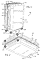
Figs. 1 and 2 , awheeled luggage article 100 according to an example of the invention includes a generallycuboid structure 105 formed from a plurality of walls 102,104,106,108,110,112 defining an enclosed internal volume of theluggage article 100 in which to carry a user's belongings. Theluggage article 100 includes opposing front and rear walls 102,104, opposing side walls 106,108, and opposing top and bottom end walls 110,112 that collectively define a housing orouter structure 105 of theluggage article 100. Theluggage article 100 may be a bag, a case, or other luggage articles. Theluggage article 100 may be hard and/or soft sided. - The
luggage article 100 may be split along anopening line 114 into alid section 116, which includes thefront wall 102, and abase section 118, which includes the rear wall 104. Thelid section 116 may be connected to thebase section 118 along a portion of a side of thearticle 100 via ahinge 120 in a conventional manner, and theluggage article 100 may be opened at theopening line 114 to access the internal volume. Thehinge 120 may be formed of azipper 122 and a fabric strip, a piano hinge, discrete hinges spaced apart, or an articulating joint. The piano hinge, the discrete hinges, or the articulating joint may be made from metal, plastic, any other suitable material, or any combination thereof. Thehinge 120 may be stitched to thelid 116 and also to thebase 118, or may be coupled in another suitable manner. Azipper 122 along a periphery of theopening line 114 or other conventional closure arrangement, for example clamp locks, may secure thelid section 116 to thebase section 118 to close theluggage article 100. - The
luggage article 100 may include at least one handle. The depictedluggage article 100 includes a telescoping tow handle 124 associated with thetop wall 112. The depicted case also includes fixed carry handles 126 attached to thetop wall 112 and theside wall 106. Thetelescoping handle 124 and the fixed carry handles 126 may be associated with any wall of theluggage article 100. - The
luggage article 100 may include at least onewheel assembly 128. The depictedluggage article 100 includes fourwheel assemblies 128 mounted from thebottom end wall 110 of thecase 110. Eachspinner wheel assembly 128 is located proximate a bottom end corner of thearticle 100. In other words, eachspinner wheel assembly 128 is located on thebottom end wall 110 of the case near an intersection of one of the front and rear walls 102,104 and one of the side walls 106,108 of thearticle 100. Thespinner wheel assemblies 128 may be spaced apart from one another by substantially the width and/or depth of thearticle 100. - Referring to
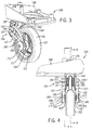
Figs. 1 to 3 , eachspinner wheel assembly 128 may include awheel mount 130, one ormore wheels 132, and awheel bracket 134. Thewheel mount 130 generally attaches thewheel bracket 134 to theluggage article 100. Thewheel mount 130 may be attached to the corners of thearticle 100 formed by the intersection of any three adjacent walls. In other embodiments thewheel mount 130 may be attached to thearticle 100 at other locations. Thebracket 134 may be rotationally mounted to thebottom end wall 110 of theluggage article 100 via thewheel mount 130 to rotate about a generally vertical spinner axis 136 (seeFigs. 4 and6 ) oriented perpendicular to thebottom end wall 110 of thearticle 100. A single wheel 132 (although a pair of wheels may be provided in other embodiments) may be rotationally mounted to thewheel bracket 134 to rotate about a wheel axis 138 (seeFig. 4 ), which is generally horizontal and parallel to thebottom wall 110 of theluggage article 100. Such an arrangement allows thespinner wheels 132 to rotate about two orthogonal axes: thevertical spinner axis 136 and thehorizontal wheel axis 138. Thespinner wheel assemblies 128 support theluggage article 100 in a vertical upright orientation relative to a support surface and generally allows thearticle 100 to be wheeled along the support surface in a stable upright orientation as shown inFig. 1 . In other embodiments, theluggage article 100 may include at least one wheel having a fixed vertical axis and configured to allow rolling movement of the luggage case. - Referring to
Figs. 3-6 , thewheel bracket 134 may include two main components: asupport member 140 and asuspension member 142. Thesupport member 140 may be vertically fixed, but swivelable, relative to thewheel mount 130. As shown inFig. 6 , anupper portion 142 of thesupport member 140 may be received within and rotatably bear against an inner surface of an upwardly-extendingsleeve 146 that is formed as part of thewheel mount 130, and alower portion 144 of thesupport member 140 may be positioned beneath thewheel mount 130. To limit or prevent vertical displacement of thesupport member 140 relative to thewheel mount 130, a fastener, such as the c-clip 148 shown inFig. 6 , may be received within an annular groove formed in theupper portion 142 and abut against an upper surface of thesleeve 146, and an annular, upper shoulder of thelower portion 144 of thesupport member 140 may abut against a lower surface of thewheel mount 130. Thesupport member 140 may be metallic, non-metallic, or both. In some implementations, thesupport member 140 is formed from steel, titanium, plastic, or other suitable materials. - Referring to
Figs. 3-7 , thesuspension member 142 may include first and secondelongate arms wheel 132. The first and secondelongate arms wheel 132, thereby reducing the forces transferred to theouter structure 105. The first and secondelongate arms elongate arms elongate arms elongate arms second arms Fig. 7 , or alternatively may be formed as separate pieces and joined together with a hub connector. - With continued reference to
Figs. 3-7 , the first and secondelongate arms lower portion 144 of thesupport member 140. Thesupport member 140 may receiveend portions second arms end portions lower portion 144 of thesupport member 140. Eachend portion support member 140. Thesupport member 140 may include individual arm coverings orhousings 157 that extend laterally from the sides of thesupport member 140 and surround a portion of the first andsecond arms end portions arms support member 140. Thearm coverings 157 may be formed as part of asupport member insert 159, which may be interference fit or otherwise attached to thesupport member 140. - From the
end portions elongate arms support member 140. The first andsecond arms second arms 150, 152 (seeFigs. 3 and7 ). Thefirst arm 150 may be positioned directly above thesecond arm 152, and the first andsecond arms second arms central axis 138 of thewheel 132. Near thecentral axis 138 of thewheel 132, the first andsecond arms wheel axle 162. Thewheel mount 158 may extend at least partially around thecentral axis 138 of thewheel 132. - The
wheel mount 158 may be received within ahub insert 163 that holds thewheel mount 158 wrapped around thewheel axle 162. Thehub insert 163 may be positioned outwardly from ahub 167 of thewheel 132 coaxially along thecentral axis 138 of the wheel 132 (seeFigs. 3 and 4 ). Thehub insert 163 may be ring-shaped and may include anouter portion 165 that extends radially around a majority of thewheel mount 158. Theouter portion 165 may define a neck opening orportion 169 that opens to an internal space of thehub insert 163 and permits passage of theelongate arms - The
hub insert 163 may be secured to thewheel axle 162 by ahub fastener 171. Thehub fastener 171 may include ahead portion 173 and ashank portion 175 extending from an underside of thehead portion 173. Thehead portion 173 may abut against an outer surface of thehub insert 163, and theshank portion 175 may pass through thehub insert 163 and engage thewheel axle 162 to attach thehub insert 163 to thehub 167 of thewheel 132. Thehead portion 173 may define a hexagonal socket or other engagement feature for engagement with a tool, such as a hexagonal key. Theshank portion 175 may be externally threaded for engagement with an internally-threaded end portion of thewheel axle 162. - To attach the first and
second arms wheel 132, thewheel mount 158 may be pressed through theneck portion 169 of thehub insert 163 and positioned in the internal space of thehub insert 163. Thewheel mount 158 may be interference fit within thehub insert 163 such that thewheel mount 158 abuts against an inner surface of thehub insert 163 and rotates in unison with thehub insert 163 about thecentral axis 138 of thewheel 132. Thewheel mount 158 and thehub insert 163 may be mounted onto an end portion of theaxle 162 such that thewheel mount 158 is positioned radially between thewheel axle 162 and theouter portion 165 of thehub insert 163. To positively locate thehub insert 163 along thecentral axis 138 of thewheel 132, theshank portion 175 of thehub fastener 171 may be threaded into engagement with the internally-threaded end portion of theaxle 162 until thehead portion 173 of thehub fastener 171 abuts against a confronting surface of thehub insert 163, thereby securing thehub insert 163 along thewheel axis 138 adjacent to thehub 167 of thewheel 132. - The first and
second arms second arms Figs. 1-10 , the flexural rigidity or bending stiffness of the first andsecond arms arms - Referring to
Figs. 3-7 , thesecond arm 152 has a larger bending stiffness than thefirst arm 150 based primarily on the relative geometric profiles or shapes of the first andsecond arms second arm 152 extends in a straight line or a substantially straight (slightly curved) line from thesupport member 140 toward thecentral axis 138 of thewheel 132, whereas thefirst arm 150 extends in an arcuate or curved path from thesupport member 140 toward thecentral axis 138 of thewheel 132. In this configuration, thesecond arm 152 determines the travel path of thewheel 132 and pivots about the attachment point of thesecond arm 152 to thesupport member 140, and thefirst arm 150 resiliently bends, buckles, or flexes as thesecond arm 152 pivots, thereby providing a spring function that absorbs impact energy such as vibrations. - With further reference to
Figs. 3-7 , thesuspension member 142 may include third and fourthelongate arms wheel 132 relative to the first and secondelongate arms elongate arms lower portion 144 of thesupport member 140. The third and fourthelongate arms elongate arms fourth arms support member 140 relative to the first and secondelongate arms support member 140, thesuspension member 142 may be symmetrical about a vertical plane bisecting thesupport member 140. - The
support member 140 may receiveend portions fourth arms end portions lower portion 144 of thesupport member 140 relative to theend portions second arms end portions fourth arms end portions second arms end portion support member 140. Thesupport member 140 may include individual arm coverings orhousings 157 that extend laterally from the sides of thesupport member 140 and surround a portion of the third andfourth arms end portions support member 140. - From the
end portions elongate arms support member 140 in a uniformly-spaced relationship with the first and secondelongate arms 150, 152 (seeFigs. 3, 4 , and7 ). The third andfourth arms fourth arms 154, 156 (seeFigs. 5 and7 ). Thethird arm 154 may be positioned directly above thefourth arm 156, and the third andfourth arms fourth arms central axis 138 of thewheel 132. Near thecentral axis 138 of thewheel 132, the third andfourth arms cantilevered wheel mount 160 for receiving an opposing end of thewheel axle 162 relative to the firstcantilevered wheel mount 160. Thewheel mount 160 may extend at least partially around thecentral axis 138 of thewheel 132, and thewheel mount 160 may be attached to an opposing end portion of thewheel axle 162 relative to thewheel mount 158 with ahub insert 163 andhub fastener 171 as described above in relation to thewheel mount 158. As shown inFig. 7 , the third andfourth arms first arm 150, thesecond arm 152, thethird arm 154, and thefourth arm 156 are formed from a single wire as one piece. In other implementations, thefirst arm 150, thesecond arm 152, thethird arm 154, and thefourth arm 156 are formed from four separate wire pieces and joined together by hub connectors positioned on opposing sides of thewheel 132. - The third and
fourth arms fourth arms Figs. 1-10 , the flexural rigidity or bending stiffness of the third andfourth arms arms - Referring to
Figs. 3-7 , thefourth arm 156 may be more rigid than thethird arm 154. Thefourth arm 156 may extend in a straight line or a substantially straight (slightly curved) line from thesupport member 140 toward thecentral axis 138 of thewheel 132, whereas thethird arm 154 may extend in an arcuate or curved path from thesupport member 140 toward thecentral axis 138 of thewheel 132. In this configuration, thefourth arm 156 determines the travel path of thewheel 132 and pivots about the attachment point of thefourth arm 156 to thesupport member 140, and thethird arm 154 resiliently bends, buckles, or flexes as thefourth arm 156 pivots, thereby providing a spring function that absorbs impact energy such as vibrations. - Referring to
Figs. 3 ,5, and 6 , thewheel 132 may abut directly against thesupport member 140 to limit the maximum deflection of thewheel 132 and thearms support member 140 may include awheel abutment 164 adapted to contact acircumferential surface 166 of thewheel 132 to limit deformation of thearms wheel 132. Thewheel abutment 164 may include acurved brake surface 168 having a curvature that substantially corresponds to or matches a circumference of the wheel 132 (seeFigs. 5 and 6 ). The curvedinner surface 168 of thewheel abutment 164 is adapted to contact the outercircumferential surface 166 of thewheel 132, thereby providing a positive stop to the travel of thewheel 132 and preventing plastic deformation of thearms Fig. 8 ). Thearms brake surface 168 of thewheel abutment 164 only contacts thecircumferential surface 166 of thewheel 132 when theluggage article 100 is loaded over a weight capacity of thearticle 100 and a sufficiently large impact force is imparted on thearticle 100, thewheel 132, or both. - During operation, the
elongate arms wheel 132, thereby reducing the forces transferred to theouter structure 105. Referring toFig. 8 , awheel 132 is rotationally attached to the cantilevered wheel hub or mounts 158, 160 of thewheel bracket 134. Thewheel 132 and the first andsecond arms lower arm 152 may pivot upwardly towards thewheel mount 130 about a pivot axis defined by thesupport member 140 with little to no bending, thereby defining the travel path of thewheel 132. The first orupper arm 150 may resiliently deform along its length, permitting the upwardly movement of thewheel 132 while absorbing impact energy to provide more silent and smooth rolling. - The
suspension member 142 may be formed from various materials. Theelongate arms elongate arms elongate arms elongate arms elongate arms elongate arms - Referring to
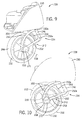
Figs. 9 and 10 , analternative wheel bracket 234 that may be used with theluggage article 100 is depicted. The reference numerals used inFigs. 9 and 10 correspond to the reference numerals used inFigs. 1-8 to reflect similar parts and components, except the first digit of each reference numeral is incremented by one. Thealternative wheel bracket 234, forming part of thewheel assembly 228, has the same features and operation as the firstexample wheel bracket 134 depicted inFigs. 1-8 , except the cantileveredwheel mount 258 is circular and encloses thecentral axis 138 of thewheel 132 and thewheel bracket 234 does not includearm coverings 157 or asupport member insert 159 to secure thearms support member 240. Accordingly, the preceding discussion of the features and operation of thewheel bracket 134 should be considered equally applicable to thealternative wheel bracket 234. - Referring to
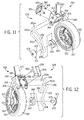
Figs. 11-17 , analternative wheel bracket 334 that may be used with theluggage article 100 is depicted. The reference numerals used inFigs. 11-17 correspond to the reference numerals used inFigs. 1-8 to reflect similar parts and components, except the first digit of each reference numeral is incremented by two. Thealternative wheel bracket 334, forming part of thewheel assembly 328, has the same features and operation as the firstexample wheel bracket 134 depicted inFigs. 1-8 , except the connection of theelongate arms support member 140 and to thewheel 132 is modified. Accordingly, the preceding discussion of the features and operation of thewheel bracket 134 should be considered equally applicable to thealternative wheel bracket 334. - Referring to
Figs. 11-15 , thewheel bracket 334 may include anarm lock plate 359 that secures theelongate arms support member 340. Thearm lock plate 359 may include abase portion 378 and four pins orprongs 380 projecting outwardly from thebase portion 378. Thepins 380 may be cantilevered from thebase portion 380 such that eachpin 380 has a fixed end and a free end. The free end of eachpin 380 may include abarb 388 and may be referred to as a barbed end. Thepins 380 may extend parallel to one another. Thepins 380 may be received inbores 382 defined in thesupport member 340. Thebores 382 may extend transversely to and intersectarm openings 384 formed in thesupport member 340. Thearm openings 384 may receive theend portions arms Fig. 15 ). - To attach the
arms support member 340, theend portions arm openings 384 until a cut out or notch 386 formed in each of the end portions is aligned with thebores 382. Once theindividual notches 386 and bores 382 are aligned, thearm lock plate 359 may be snapped into thesupport member 340 to lock thearms arm lock plate 359 may be moved relative to thesupport member 340 until thepins 380 are aligned with thebores 382, which may extend perpendicularly to thearm openings 384. Thepins 380 may be inserted into thebores 382 and through thenotches 386 in thearms end portions arms support member 340. Once assembled to thesupport member 340, thearm lock plate 359 may prevent the end portions of the arms from moving in a direction that is parallel to thewheel axis 338. - One or more of the
pins 380 may include a feature that secures thearm lock plate 359 to thesupport member 340. As shown inFigs. 13 and 14 , abarb 388 may be formed on one or more of the free ends of thepins 380. Thebarb 388 may engage a retainingshoulder 390 of thesupport member 340 to secure thearm lock plate 359 to thesupport member 340 and ensure thepins 380 remain interlocked with thearms recess 392 may be formed in the free end of eachpin 380 to facilitate insertion of the barbed ends of thepins 380 through thebores 382. - Referring to
Figs. 11, 12 ,16, and 17 , the attachment of thearms wheel axle 362 is depicted. Similar to other examples described above, thearms wheel axle 362. As shown inFigs. 11, 12 , and16 , thearms wheel axle 362 to prevent the axle from slipping out of thewheel mount optional hub insert 363 may hold the wheel mounts 358, 360 wrapped around thewheel axle 362 to prevent the wheel mounts 358, 360 from being dislodged from theaxle 362. In implementations using ahub insert 363, thearms hub insert 363 through a narrowedneck portion 369 of theinsert 363. Thearms axle 362 radially between theaxle 362 and the outer portion 365 of theinsert 363. - The wheel mounts 358, 360 may be positioned adjacent to opposing sides of the
hub 367 of thewheel 332, and ashank portion 375 of ahub fastener 371 may engage an end portion of theaxle 362 to axially secure thehub insert 363 to theaxle 362. Thehub fastener 371 may be threaded or pressed into engagement with theaxle 362, for example. Eachwheel mount end portion 362a of thewheel axle 362 such that the wheel mounts 358, 360 are located on opposing axial sides of thewheel 332. The wheel mounts 358, 360 may be secured axially between thehead portion 373 of thehub fasteners 371 and thehub 367 of thewheel 332. Thehub fasteners 371, the wheel mounts 358, 360, and theaxle 362 may form a solid construction so the wheel may rotate freely about theaxle 362. Thehub fasteners 371, the wheel mounts 358, 360, and thewheel axle 362 may be coaxially aligned with one another along thecentral axis 338 of thewheel 332. As shown inFigs. 16 and 17 , the wheel mounts 358, 360 may be positioned within hub inserts 363. A washer may be positioned between the wheel mounts 358, 360 and the respective sides of thehub 367. - Relative to conventional luggage wheel brackets, the wheel bracket of the present disclosure generally results in quieter wheel operation with reduced weight. The wheel bracket generally absorbs or attenuates more shock and/or vibrational loads during rolling than conventional luggage wheel brackets, resulting in reduced noise and substantially silent rolling. In some implementations, the wheel bracket includes two spaced-apart, elongate arms that provide suspension to the wheel bracket due to one of the arms pivoting about a reference point and another of the arms bending, buckling, or flexing. The pivoting arm may be straight or substantially straight and may have a higher flexural rigidity or bending stiffness than the bending or buckling arm, which may be arcuate or curved. The arm with the lower flexural rigidity or bending stiffness may provide resilience as the arm with the higher flexural rigidity or bending stiffness pivots, thereby absorbing impact energy such as vibrational loads. The elongate arms may form a cantilevered mount for a wheel and may provide a shock absorbing function, resulting in less components and reduced weight relative to conventional luggage wheel brackets. Preferably the elongate arms are formed from wire.
- The luggage wheel bracket of the present disclosure has broad application. For instance, the wheel bracket may be used with a single spinner wheel, a double spinner wheel, and/or an upright wheel. In implementations utilizing a single wheel, the suspension member may include a single pair of elongate arms extending along a common side of the wheel or a double pair of elongate arms extending along opposing sides of the wheel. In implementations utilizing a double wheel, the suspension member may include a single pair of elongate arms extending between the double wheels. The depicted arrangement of the arms (with the upper arm being arcuate or curved and the lower arm being straight or substantially straight) may be reversed with the upper arm being straight or substantially straight and the lower arm being arcuate or curved. Both elongate arms may be arcuate or curved, preferably with one arm defining a greater amount of curvature than the other arm. The depicted arrangement of the arms (with the upper and lower arms on each side of the wheel formed from a single piece of material) may be altered with the upper and lower arms on each side of the wheel formed from separate pieces of material and joined together by hub connectors or with the upper and lower arms on both sides of the wheel formed from a single piece of material. The luggage wheel bracket of the present disclosure may be used with a hard side suitcase, a soft side case, a hybrid side case, or various types of bags.
- The apparatuses and associated methods in accordance with the present disclosure have been described with reference to particular embodiments thereof in order to illustrate the principles of operation. The above description is thus by way of illustration and not by way of limitation. In methodologies directly or indirectly set forth herein, various steps and operations are described in one possible order of operation, but those skilled in the art will recognize that the steps and operations may be rearranged, replaced, or eliminated without necessarily departing from the spirit and scope of the disclosed embodiments.
- All relative and directional references (including: upper, lower, upward, downward, left, right, leftward, rightward, top, bottom, side, above, below, front, middle, back, vertical, horizontal, and so forth) are given by way of example to aid the reader's understanding of the particular embodiments described herein. They should not be read to be requirements or limitations, particularly as to the position, orientation, or use of the invention unless specifically set forth in the claims. Connection references (e.g., attached, coupled, connected, joined, and the like) are to be construed broadly and may include intermediate members between a connection of elements and relative movement between elements. As such, connection references do not necessarily infer that two elements are directly connected and in fixed relation to each other, unless specifically set forth in the claims.
Claims (16)
- A luggage article comprising:a plurality of walls (102,104,106,108,110,112) together defining an outer structure (105) of the luggage article (100); andone or more wheel assemblies (128,228,328) attached to and extending from one of the walls, the one or more wheel assemblies comprising:a wheel bracket (134,234,334) attached to and extending from one of the walls; anda wheel (132,232,332) attached to the wheel bracket;characterized in that the wheel bracket comprises a first arm (150,250,350) and a second arm (152,252,352) extending along a common side of the wheel and vertically-spaced apart from one another over at least a portion of the length of the first and second arms.
- A luggage article as claimed in claim 1 wherein the first and second arms (150,250,350,152,252,352) have different bending stiffness.
- A luggage article as claimed in any preceding claim wherein the first arm (150,250,350) is positioned directly above the second arm (152,252,352).
- A luggage article as claimed in any preceding claim wherein the first and second arms (150,250,350,152,252,352) converge toward one another as the first and second arms approach a central axis (138,238,338) of the wheel (132,232,332).
- A luggage article as claimed in any preceding claim wherein the first and second arms (150,250,350,152,252,352) form a cantilevered wheel mount (158,258,358) that extends at least partially around a central axis (138,238,338) of the wheel (132,232,332).
- A luggage article as claimed in claim 5 wherein the cantilevered wheel mount (158,358) is positioned within a hub insert (163,363), and wherein a wheel axle (162,362) passes through the hub insert (163,363).
- A luggage article as claimed in any preceding claim wherein the first and second arms (150,250,350,152,252,352) are solid or single-stranded wire.
- A luggage article as claimed in any preceding claim wherein the first arm (150,250,350) is arcuate, and wherein the second arm (152,252,352) is straight or substantially straight.
- A luggage article as claimed in any preceding claim wherein the first and second arms (150,250,350,152,252,352) are formed as a single component.
- A luggage article as claimed in any preceding claim wherein the wheel bracket (134,234,334) further comprises a support member (140,240,340) that receives end portions (150a,250a,350a;152a,252a,352a) of the first and second arms (150,250,350;152,252,352), and wherein the end portions are vertically-spaced apart from one another.
- A luggage article as claimed in claim 10 wherein the support member (140,240,340) defines a wheel abutment (164,264,364) that is adapted to contact a circumferential surface (166,266,366) of the wheel (132,232,332), thereby limiting the wheel travel of the wheel and the resilient deformation of the first and second arms (150,250,350;152,252,352).
- A luggage article as claimed in claims 10 or 11 wherein the first and second arms (350,352) each define a notch (386), and wherein the support member (340) includes a support member insert (359) having multiple prongs (380) that engage the notches to interlock the first and second arms to the support member.
- A luggage article as claimed in any preceding claim wherein the wheel bracket (134,234,334) further comprises third and fourth elongate arms (154,254,354;156,256,356) that extend along an opposing side of the wheel (132,232,332) relative to the first and second arms (150,250,350;152,252,352).
- A luggage article as claimed in claim 12 wherein the first, second, third, and fourth arms (150,250,350,152,252,352,154,254,354,156,256,356) are formed as a single component.
- A luggage article as claimed in any preceding claim wherein the wheel bracket (134,234,334) and the wheel (132,232,332) form part of a spinner wheel assembly (128,228,328).
- A wheel assembly for a luggage article, the wheel assembly comprising:a wheel bracket (134,234,334); anda wheel (132,232,332) attached to the wheel bracket;characterized in that the wheel bracket comprises a first arm (150,250,350) and a second arm (152,252,352) extending along a common side of the wheel and vertically-spaced apart from one another over at least a portion of the length of the first and second arms.
Priority Applications (8)
| Application Number | Priority Date | Filing Date | Title |
|---|---|---|---|
| EP13188762.2A EP2862473B1 (en) | 2013-10-15 | 2013-10-15 | Luggage article with a cantilevered wheel bracket having elongated arms |
| JP2014210694A JP2015077966A (en) | 2013-10-15 | 2014-10-15 | Bag article using cantilever-beam type wheel bracket including thin and long arm |
| AU2014250651A AU2014250651A1 (en) | 2013-10-15 | 2014-10-15 | Luggage article with cantilevered wheel bracket having elongated arms |
| KR20140139005A KR20150044005A (en) | 2013-10-15 | 2014-10-15 | Luggage article with cantilevered wheel bracket having elongated arms |
| US14/514,737 US9636948B2 (en) | 2013-10-15 | 2014-10-15 | Luggage article with cantilevered wheel bracket having elongated arms |
| CN201410545178.4A CN104544847B (en) | 2013-10-15 | 2014-10-15 | Luggage case with the cantilevered wheel bracket with slender arm |
| CN201420596235.7U CN204378187U (en) | 2013-10-15 | 2014-10-15 | A kind of luggage case and the wheel assembly for luggage case |
| TW103135632A TW201521630A (en) | 2013-10-15 | 2014-10-15 | Luggage article with cantilevered wheel bracket having elongated arms |
Applications Claiming Priority (1)
| Application Number | Priority Date | Filing Date | Title |
|---|---|---|---|
| EP13188762.2A EP2862473B1 (en) | 2013-10-15 | 2013-10-15 | Luggage article with a cantilevered wheel bracket having elongated arms |
Publications (2)
| Publication Number | Publication Date |
|---|---|
| EP2862473A1 true EP2862473A1 (en) | 2015-04-22 |
| EP2862473B1 EP2862473B1 (en) | 2018-08-22 |
Family
ID=49356307
Family Applications (1)
| Application Number | Title | Priority Date | Filing Date |
|---|---|---|---|
| EP13188762.2A Not-in-force EP2862473B1 (en) | 2013-10-15 | 2013-10-15 | Luggage article with a cantilevered wheel bracket having elongated arms |
Country Status (7)
| Country | Link |
|---|---|
| US (1) | US9636948B2 (en) |
| EP (1) | EP2862473B1 (en) |
| JP (1) | JP2015077966A (en) |
| KR (1) | KR20150044005A (en) |
| CN (2) | CN204378187U (en) |
| AU (1) | AU2014250651A1 (en) |
| TW (1) | TW201521630A (en) |
Cited By (6)
| Publication number | Priority date | Publication date | Assignee | Title |
|---|---|---|---|---|
| US9616562B2 (en) | 2014-07-22 | 2017-04-11 | Milwaukee Electric Tool Corporation | Tool storage devices |
| US9872547B2 (en) | 2015-11-25 | 2018-01-23 | Milwaukee Electric Tool Corporation | Handle assembly for a case |
| USD811090S1 (en) | 2016-06-27 | 2018-02-27 | Samsonite Ip Holdings S.A R.L. | Luggage wheel housing with a wheel |
| USD844324S1 (en) | 2015-07-17 | 2019-04-02 | Milwaukee Electric Tool Corporation | Bag |
| US10897970B2 (en) | 2015-03-31 | 2021-01-26 | Samsonite Ip Holdings S.A R.L. | Luggage article with loop-shaped wheel bracket |
| US11819102B2 (en) | 2016-06-27 | 2023-11-21 | Samsonite Ip Holdings S.A R.L. | Spinner wheel assembly for a luggage case |
Families Citing this family (3)
| Publication number | Priority date | Publication date | Assignee | Title |
|---|---|---|---|---|
| AU201716528S (en) * | 2017-10-27 | 2017-11-15 | Comfortel Furniture Pty Ltd | Trolley |
| EP3593777B1 (en) * | 2018-07-10 | 2021-05-26 | TRUMPF Medizin Systeme GmbH + Co. KG | Castor suspension system |
| CN113002678A (en) * | 2019-12-20 | 2021-06-22 | 明门瑞士股份有限公司 | Wheel shock absorber structure and children's carrier |
Citations (19)
| Publication number | Priority date | Publication date | Assignee | Title |
|---|---|---|---|---|
| US2738542A (en) | 1952-04-21 | 1956-03-20 | Harry I Clark | Shock absorbing caster |
| US2914340A (en) | 1958-09-15 | 1959-11-24 | Pemco Wheel Co | Cart having spring suspended caster wheels |
| US2923961A (en) | 1960-02-09 | black | ||
| US2942290A (en) | 1957-05-14 | 1960-06-28 | George J Segal | Self-locking caster |
| US2987752A (en) | 1958-11-10 | 1961-06-13 | Pemco Wheel Co | Caster |
| EP0051995A1 (en) | 1980-11-10 | 1982-05-19 | Wheel Developments Limited | Spring member |
| US4392668A (en) | 1980-12-09 | 1983-07-12 | Mulholland Lawrence K | Shock-absorbing wheel suspension assembly |
| US4422212A (en) | 1981-07-07 | 1983-12-27 | Julius Sheiman | Non-readily detachable luggage support unit |
| US5533231A (en) * | 1994-09-12 | 1996-07-09 | Bai; Yang-Fong | Concealable caster of baggage |
| US6478315B1 (en) | 2000-11-27 | 2002-11-12 | Nick J. Manesis | Wheel assembly |
| US6539578B1 (en) * | 2000-06-15 | 2003-04-01 | Algood Casters Limited | Deflecting spring caster |
| DE20309968U1 (en) * | 2003-06-27 | 2003-08-28 | Wang King Sheng | Wheel unit for luggage has frame with upright wall, roller unit and pin with elastic part to press against side and absorb vibrations |
| CN201194600Y (en) | 2008-02-29 | 2009-02-18 | 卢国裕 | Luggage case truckle shock-proof structure, elastic pad and axial pin |
| CN201675239U (en) | 2010-04-23 | 2010-12-22 | 东莞贺捷塑胶有限公司 | Shock absorbing dragging roller |
| US20110168508A1 (en) | 2010-01-14 | 2011-07-14 | Hanhui Jiang | Anti-vibration suitcase wheel and suitcase using the same |
| CN202278929U (en) | 2011-09-30 | 2012-06-20 | 皇冠皮件工业股份有限公司 | Anti-vibration caster wheel |
| CN102578778A (en) | 2012-03-16 | 2012-07-18 | 陈宏伟 | Shock-absorbing universal wheel for luggage |
| CN202407510U (en) | 2012-01-20 | 2012-09-05 | 张意立 | Double-disc-shaped spoke spring vibration absorption travel suitcase |
| CN202528768U (en) | 2012-04-30 | 2012-11-14 | 张意立 | Dual-saucer-shaped spoke spring shockproof wheel for travel suitcase |
Family Cites Families (52)
| Publication number | Priority date | Publication date | Assignee | Title |
|---|---|---|---|---|
| US2086557A (en) | 1934-10-24 | 1937-07-13 | Allied Engineering Company | Roller skate |
| GB450893A (en) | 1935-04-13 | 1936-07-27 | Grosvenor Castor Mfg Company L | Improvements in castors for furniture and the like |
| US2830545A (en) * | 1954-01-21 | 1958-04-15 | Aircraft Tool Engineering Co | Castor construction |
| US3102744A (en) | 1959-03-26 | 1963-09-03 | Mobay Chemical Corp | Ball and socket joint |
| US3222708A (en) * | 1961-12-15 | 1965-12-14 | Bliss & Laughlin Inc | Anti-fouling caster |
| US3214786A (en) * | 1962-11-15 | 1965-11-02 | Faultless Caster Corp | Caster wheel scraper |
| US4027898A (en) * | 1976-04-07 | 1977-06-07 | Southwest Wheel And Manufacturing Company | Level load leaf spring drop axle |
| US4336629A (en) * | 1981-01-19 | 1982-06-29 | Rose Truck And Caster Company | Caster swivel lock |
| US4403784A (en) | 1981-01-22 | 1983-09-13 | Gray Robert C | Roller skate axle suspension |
| US4759097A (en) | 1983-04-26 | 1988-07-26 | Standex International Corporation | Wheel bracket assembly having two part wheel bracket and a method of making the wheel bracket assembly |
| US4649595A (en) | 1985-10-02 | 1987-03-17 | Shepherd Products U.S. Inc. | Resiliently mounted caster having a pivotally mounted inner body member |
| FR2763285B1 (en) | 1997-05-13 | 1999-06-11 | Emmerez De Charmoy Dennisson R | SUSPENSION FOR FREE PIVOTING WHEEL |
| US5967535A (en) * | 1997-08-14 | 1999-10-19 | Graco Children's Products Inc. | Swivel wheel mount |
| DE19845236C1 (en) * | 1998-10-01 | 2000-03-23 | Thomas Wagner Gmbh | Roller for suitcase has roller mounted by pivot arm with damping pads within casing |
| JP4435956B2 (en) * | 1999-09-21 | 2010-03-24 | カヤバ工業株式会社 | caster |
| FR2799179B3 (en) | 1999-10-04 | 2002-02-01 | Eric Alliot | FRONT AND REAR WHEEL SHOCK ABSORBER DEVICE |
| US6357793B1 (en) * | 1999-10-29 | 2002-03-19 | Sunrise Medical Hhg Inc. | Anti-tip wheel |
| US6409196B1 (en) * | 1999-11-22 | 2002-06-25 | Mcfarland Ryan J. | Wheelchair front fork |
| TW445794U (en) * | 2000-12-13 | 2001-07-11 | Chaw Khong Technology Co Ltd | Structure of shock-absorbing caster for travelling case |
| US6550100B2 (en) * | 2001-02-08 | 2003-04-22 | Waxman Industries, Inc. | Caster assembly with multi-position support pieces |
| EP1392552A1 (en) * | 2001-05-16 | 2004-03-03 | Dynamic Products Limited | A mobile load carrier with castor mounting arrangement |
| US6789810B2 (en) * | 2001-06-15 | 2004-09-14 | Russell W. Strong | Integrated wheel suspension system |
| US6776428B2 (en) * | 2001-06-15 | 2004-08-17 | Russell W. Strong | Forward extending wheel suspension system |
| US6892421B2 (en) * | 2002-12-11 | 2005-05-17 | The United States Of America As Represented By The Department Of Veterans Affairs | Oblique angled suspension caster fork for wheelchairs |
| NL1023789C2 (en) * | 2003-07-01 | 2005-01-04 | Bugaboo Design And Sales B V | Pram with spring wheel, spring wheel and swivel castor. |
| GB0411376D0 (en) * | 2004-05-21 | 2004-06-23 | Trw Ltd | Suspension apparatus |
| US7213818B2 (en) * | 2004-08-24 | 2007-05-08 | Abmex Enterprise Co., Ltd. | Stroller having wheel rotation control device |
| US20080116660A1 (en) * | 2005-01-19 | 2008-05-22 | Kevin Nicholls | Elastomeric Wheelchair Suspension |
| US7891051B2 (en) * | 2005-04-22 | 2011-02-22 | Haion Caster Industrial Co., Ltd. | Wheel assembly |
| US7210690B2 (en) * | 2005-05-17 | 2007-05-01 | Yi-Cheng Tan | Direction-limiting device for stroller |
| US7744102B2 (en) * | 2005-07-09 | 2010-06-29 | Eric Shawn Bailey | Steerable carriage apparatus |
| US20070056141A1 (en) * | 2005-09-15 | 2007-03-15 | Sergio Armano | Powered locking caster wheel |
| US8452508B2 (en) * | 2005-11-10 | 2013-05-28 | Linet Spol. S.R.O. | Braking system for patient support |
| US7546908B2 (en) * | 2005-11-28 | 2009-06-16 | Chin-Lin Chang | Wheel assembly |
| ITMI20052484A1 (en) * | 2005-12-23 | 2007-06-24 | Ogtm Officine Meccaniche Srl | STRAIGHT WHEEL STRUCTURE PARTICULARLY PERFECTED FOR FURNITURE AND SIMILAR |
| EP2001709B1 (en) | 2006-04-03 | 2010-11-10 | Graco Children's Products Inc. | Cup holder for a stroller |
| US7614115B2 (en) * | 2007-07-31 | 2009-11-10 | Li-Lan Yan | Wheel structure with a central control |
| US7984917B2 (en) | 2008-04-04 | 2011-07-26 | Seal Trademarks Pty Ltd | Suspension skateboard truck |
| CN102770283B (en) * | 2010-02-25 | 2015-05-13 | 株式会社日乃本锭前 | Caster system equipped with hand-operated brakes |
| US20120005858A1 (en) * | 2010-07-06 | 2012-01-12 | Herson Plastic Co. Ltd. | Wheel assembly with single fixing arm |
| CN201768099U (en) | 2010-07-08 | 2011-03-23 | 厦门连科工业有限公司 | Wheelchair front fork suspension structure |
| US8490243B2 (en) * | 2010-10-08 | 2013-07-23 | Wonderland Nurserygoods Company Limited | Wheel assembly for an infant carrier apparatus |
| JP5466683B2 (en) | 2010-10-08 | 2014-04-09 | 明門香港股▲フェン▼有限公司 | Wheel assembly and stroller for infant carrier |
| FR2965754B1 (en) | 2010-10-08 | 2012-11-02 | Tente Roulettes Polymeres Bruandet | DAMPER WHEEL |
| US20120255141A1 (en) * | 2011-04-06 | 2012-10-11 | Ming-Hsien Lin | Castor Assembly |
| CN102991559B (en) | 2011-09-15 | 2016-04-27 | 明门香港股份有限公司 | The caster device of doll carriage |
| WO2013131188A1 (en) * | 2012-03-05 | 2013-09-12 | Slagerman Murray G | Wheelchair caster mounting assembly |
| CN202782503U (en) | 2012-09-12 | 2013-03-13 | 广州铭泽金属制品有限公司 | Vibration reducing wheel with double vibration reduction |
| CN202822656U (en) * | 2012-10-12 | 2013-03-27 | 宁波稳泰运动器材有限公司 | Improved type golf cart |
| US8807584B2 (en) * | 2012-12-19 | 2014-08-19 | Lasher Sport, LLC. | Stabilizing device and method for handcycle |
| US20140262661A1 (en) * | 2013-03-14 | 2014-09-18 | Travelpro International, Inc. | Wheel Assembly, Method, and Luggage |
| EP3075567A1 (en) | 2015-03-31 | 2016-10-05 | Samsonite IP Holdings S.à.r.l. | Luggage article with loop-shaped wheel bracket |
-
2013
- 2013-10-15 EP EP13188762.2A patent/EP2862473B1/en not_active Not-in-force
-
2014
- 2014-10-15 AU AU2014250651A patent/AU2014250651A1/en not_active Abandoned
- 2014-10-15 KR KR20140139005A patent/KR20150044005A/en not_active Application Discontinuation
- 2014-10-15 US US14/514,737 patent/US9636948B2/en not_active Expired - Fee Related
- 2014-10-15 CN CN201420596235.7U patent/CN204378187U/en not_active Expired - Fee Related
- 2014-10-15 JP JP2014210694A patent/JP2015077966A/en active Pending
- 2014-10-15 CN CN201410545178.4A patent/CN104544847B/en not_active Expired - Fee Related
- 2014-10-15 TW TW103135632A patent/TW201521630A/en unknown
Patent Citations (19)
| Publication number | Priority date | Publication date | Assignee | Title |
|---|---|---|---|---|
| US2923961A (en) | 1960-02-09 | black | ||
| US2738542A (en) | 1952-04-21 | 1956-03-20 | Harry I Clark | Shock absorbing caster |
| US2942290A (en) | 1957-05-14 | 1960-06-28 | George J Segal | Self-locking caster |
| US2914340A (en) | 1958-09-15 | 1959-11-24 | Pemco Wheel Co | Cart having spring suspended caster wheels |
| US2987752A (en) | 1958-11-10 | 1961-06-13 | Pemco Wheel Co | Caster |
| EP0051995A1 (en) | 1980-11-10 | 1982-05-19 | Wheel Developments Limited | Spring member |
| US4392668A (en) | 1980-12-09 | 1983-07-12 | Mulholland Lawrence K | Shock-absorbing wheel suspension assembly |
| US4422212A (en) | 1981-07-07 | 1983-12-27 | Julius Sheiman | Non-readily detachable luggage support unit |
| US5533231A (en) * | 1994-09-12 | 1996-07-09 | Bai; Yang-Fong | Concealable caster of baggage |
| US6539578B1 (en) * | 2000-06-15 | 2003-04-01 | Algood Casters Limited | Deflecting spring caster |
| US6478315B1 (en) | 2000-11-27 | 2002-11-12 | Nick J. Manesis | Wheel assembly |
| DE20309968U1 (en) * | 2003-06-27 | 2003-08-28 | Wang King Sheng | Wheel unit for luggage has frame with upright wall, roller unit and pin with elastic part to press against side and absorb vibrations |
| CN201194600Y (en) | 2008-02-29 | 2009-02-18 | 卢国裕 | Luggage case truckle shock-proof structure, elastic pad and axial pin |
| US20110168508A1 (en) | 2010-01-14 | 2011-07-14 | Hanhui Jiang | Anti-vibration suitcase wheel and suitcase using the same |
| CN201675239U (en) | 2010-04-23 | 2010-12-22 | 东莞贺捷塑胶有限公司 | Shock absorbing dragging roller |
| CN202278929U (en) | 2011-09-30 | 2012-06-20 | 皇冠皮件工业股份有限公司 | Anti-vibration caster wheel |
| CN202407510U (en) | 2012-01-20 | 2012-09-05 | 张意立 | Double-disc-shaped spoke spring vibration absorption travel suitcase |
| CN102578778A (en) | 2012-03-16 | 2012-07-18 | 陈宏伟 | Shock-absorbing universal wheel for luggage |
| CN202528768U (en) | 2012-04-30 | 2012-11-14 | 张意立 | Dual-saucer-shaped spoke spring shockproof wheel for travel suitcase |
Cited By (13)
| Publication number | Priority date | Publication date | Assignee | Title |
|---|---|---|---|---|
| US10773374B2 (en) | 2014-07-22 | 2020-09-15 | Milwaukee Electric Tool Corporation | Tool storage devices |
| US10086508B2 (en) | 2014-07-22 | 2018-10-02 | Milwaukee Electric Tool Corporation | Tool storage devices |
| US9616562B2 (en) | 2014-07-22 | 2017-04-11 | Milwaukee Electric Tool Corporation | Tool storage devices |
| US10897970B2 (en) | 2015-03-31 | 2021-01-26 | Samsonite Ip Holdings S.A R.L. | Luggage article with loop-shaped wheel bracket |
| US11944175B2 (en) | 2015-03-31 | 2024-04-02 | Samsonite Ip Holdings S.A R.L. | Luggage article with loop-shaped wheel bracket |
| USD844324S1 (en) | 2015-07-17 | 2019-04-02 | Milwaukee Electric Tool Corporation | Bag |
| US9872547B2 (en) | 2015-11-25 | 2018-01-23 | Milwaukee Electric Tool Corporation | Handle assembly for a case |
| USD811090S1 (en) | 2016-06-27 | 2018-02-27 | Samsonite Ip Holdings S.A R.L. | Luggage wheel housing with a wheel |
| USD841331S1 (en) | 2016-06-27 | 2019-02-26 | Samsonite Ip Holdings S.A R.L. | Luggage wheel fork with a wheel |
| USD841330S1 (en) | 2016-06-27 | 2019-02-26 | Samsonite Ip Holdings S.A R.L. | Luggage wheel fork with a wheel |
| USD841332S1 (en) | 2016-06-27 | 2019-02-26 | Samsonite Ip Holdings S.A R.L. | Luggage wheel fork with a wheel |
| USD848740S1 (en) | 2016-06-27 | 2019-05-21 | Samsonite Ip Holdings S.A R.L. | Luggage wheel |
| US11819102B2 (en) | 2016-06-27 | 2023-11-21 | Samsonite Ip Holdings S.A R.L. | Spinner wheel assembly for a luggage case |
Also Published As
| Publication number | Publication date |
|---|---|
| JP2015077966A (en) | 2015-04-23 |
| CN204378187U (en) | 2015-06-10 |
| TW201521630A (en) | 2015-06-16 |
| US9636948B2 (en) | 2017-05-02 |
| CN104544847A (en) | 2015-04-29 |
| CN104544847B (en) | 2018-12-04 |
| US20150102573A1 (en) | 2015-04-16 |
| KR20150044005A (en) | 2015-04-23 |
| EP2862473B1 (en) | 2018-08-22 |
| AU2014250651A1 (en) | 2015-04-30 |
Similar Documents
| Publication | Publication Date | Title |
|---|---|---|
| EP2862473B1 (en) | Luggage article with a cantilevered wheel bracket having elongated arms | |
| US11944175B2 (en) | Luggage article with loop-shaped wheel bracket | |
| EP2826394B1 (en) | Luggage with shell, frame, and lock | |
| US8690166B2 (en) | Cup holder for a shopping cart | |
| CN111182816B (en) | Bearing structure for bent | |
| US9498058B2 (en) | Closet storage assemblies, connectors, brackets and systems | |
| KR20140115274A (en) | Conical bearing for a wheel assembly for a luggage item | |
| US20160348959A1 (en) | Drawer assembly | |
| EP2344000A1 (en) | Hinge for a suitcase | |
| US20060010645A1 (en) | Caster with low mounting capability | |
| US7458548B2 (en) | Removable shelf locking system | |
| KR200483757Y1 (en) | Collecting clothes apparatus | |
| US20150150399A1 (en) | Foldable clothes hanger | |
| US20130256999A1 (en) | Basket-to-Frame Locking Clip | |
| US10939746B2 (en) | Rotatable hook assembly | |
| US20140376992A1 (en) | Strap connector and methods thereof | |
| TWI616150B (en) | Cord lock | |
| US8500142B1 (en) | Wheel assembly for a golf bag | |
| KR101075564B1 (en) | Hanger | |
| KR101555877B1 (en) | Supporting unit and suitcase having the same | |
| US20080283104A1 (en) | Reinforced axillary crutch with adjustable handgrip | |
| JP3198175U (en) | Storage shelf and storage system | |
| US20230098364A1 (en) | Luggage article attachment member | |
| CN104228694A (en) | Gravity self-locking hook structure | |
| US20050242104A1 (en) | Storage box handle |
Legal Events
| Date | Code | Title | Description |
|---|---|---|---|
| PUAI | Public reference made under article 153(3) epc to a published international application that has entered the european phase |
Free format text: ORIGINAL CODE: 0009012 |
|
| 17P | Request for examination filed |
Effective date: 20131015 |
|
| AK | Designated contracting states |
Kind code of ref document: A1 Designated state(s): AL AT BE BG CH CY CZ DE DK EE ES FI FR GB GR HR HU IE IS IT LI LT LU LV MC MK MT NL NO PL PT RO RS SE SI SK SM TR |
|
| AX | Request for extension of the european patent |
Extension state: BA ME |
|
| R17P | Request for examination filed (corrected) |
Effective date: 20151022 |
|
| RBV | Designated contracting states (corrected) |
Designated state(s): AL AT BE BG CH CY CZ DE DK EE ES FI FR GB GR HR HU IE IS IT LI LT LU LV MC MK MT NL NO PL PT RO RS SE SI SK SM TR |
|
| STAA | Information on the status of an ep patent application or granted ep patent |
Free format text: STATUS: EXAMINATION IS IN PROGRESS |
|
| 17Q | First examination report despatched |
Effective date: 20161103 |
|
| GRAP | Despatch of communication of intention to grant a patent |
Free format text: ORIGINAL CODE: EPIDOSNIGR1 |
|
| STAA | Information on the status of an ep patent application or granted ep patent |
Free format text: STATUS: GRANT OF PATENT IS INTENDED |
|
| INTG | Intention to grant announced |
Effective date: 20180308 |
|
| GRAS | Grant fee paid |
Free format text: ORIGINAL CODE: EPIDOSNIGR3 |
|
| GRAA | (expected) grant |
Free format text: ORIGINAL CODE: 0009210 |
|
| STAA | Information on the status of an ep patent application or granted ep patent |
Free format text: STATUS: THE PATENT HAS BEEN GRANTED |
|
| AK | Designated contracting states |
Kind code of ref document: B1 Designated state(s): AL AT BE BG CH CY CZ DE DK EE ES FI FR GB GR HR HU IE IS IT LI LT LU LV MC MK MT NL NO PL PT RO RS SE SI SK SM TR |
|
| REG | Reference to a national code |
Ref country code: GB Ref legal event code: FG4D |
|
| REG | Reference to a national code |
Ref country code: CH Ref legal event code: EP |
|
| REG | Reference to a national code |
Ref country code: AT Ref legal event code: REF Ref document number: 1031443 Country of ref document: AT Kind code of ref document: T Effective date: 20180915 |
|
| REG | Reference to a national code |
Ref country code: IE Ref legal event code: FG4D |
|
| REG | Reference to a national code |
Ref country code: DE Ref legal event code: R096 Ref document number: 602013042299 Country of ref document: DE |
|
| REG | Reference to a national code |
Ref country code: FR Ref legal event code: PLFP Year of fee payment: 6 |
|
| PGFP | Annual fee paid to national office [announced via postgrant information from national office to epo] |
Ref country code: GB Payment date: 20180823 Year of fee payment: 6 |
|
| REG | Reference to a national code |
Ref country code: NL Ref legal event code: MP Effective date: 20180822 |
|
| REG | Reference to a national code |
Ref country code: LT Ref legal event code: MG4D |
|
| PG25 | Lapsed in a contracting state [announced via postgrant information from national office to epo] |
Ref country code: LT Free format text: LAPSE BECAUSE OF FAILURE TO SUBMIT A TRANSLATION OF THE DESCRIPTION OR TO PAY THE FEE WITHIN THE PRESCRIBED TIME-LIMIT Effective date: 20180822 Ref country code: NL Free format text: LAPSE BECAUSE OF FAILURE TO SUBMIT A TRANSLATION OF THE DESCRIPTION OR TO PAY THE FEE WITHIN THE PRESCRIBED TIME-LIMIT Effective date: 20180822 Ref country code: BG Free format text: LAPSE BECAUSE OF FAILURE TO SUBMIT A TRANSLATION OF THE DESCRIPTION OR TO PAY THE FEE WITHIN THE PRESCRIBED TIME-LIMIT Effective date: 20181122 Ref country code: IS Free format text: LAPSE BECAUSE OF FAILURE TO SUBMIT A TRANSLATION OF THE DESCRIPTION OR TO PAY THE FEE WITHIN THE PRESCRIBED TIME-LIMIT Effective date: 20181222 Ref country code: SE Free format text: LAPSE BECAUSE OF FAILURE TO SUBMIT A TRANSLATION OF THE DESCRIPTION OR TO PAY THE FEE WITHIN THE PRESCRIBED TIME-LIMIT Effective date: 20180822 Ref country code: FI Free format text: LAPSE BECAUSE OF FAILURE TO SUBMIT A TRANSLATION OF THE DESCRIPTION OR TO PAY THE FEE WITHIN THE PRESCRIBED TIME-LIMIT Effective date: 20180822 Ref country code: NO Free format text: LAPSE BECAUSE OF FAILURE TO SUBMIT A TRANSLATION OF THE DESCRIPTION OR TO PAY THE FEE WITHIN THE PRESCRIBED TIME-LIMIT Effective date: 20181122 Ref country code: RS Free format text: LAPSE BECAUSE OF FAILURE TO SUBMIT A TRANSLATION OF THE DESCRIPTION OR TO PAY THE FEE WITHIN THE PRESCRIBED TIME-LIMIT Effective date: 20180822 Ref country code: GR Free format text: LAPSE BECAUSE OF FAILURE TO SUBMIT A TRANSLATION OF THE DESCRIPTION OR TO PAY THE FEE WITHIN THE PRESCRIBED TIME-LIMIT Effective date: 20181123 |
|
| PGFP | Annual fee paid to national office [announced via postgrant information from national office to epo] |
Ref country code: DE Payment date: 20181010 Year of fee payment: 6 |
|
| REG | Reference to a national code |
Ref country code: AT Ref legal event code: MK05 Ref document number: 1031443 Country of ref document: AT Kind code of ref document: T Effective date: 20180822 |
|
| PG25 | Lapsed in a contracting state [announced via postgrant information from national office to epo] |
Ref country code: LV Free format text: LAPSE BECAUSE OF FAILURE TO SUBMIT A TRANSLATION OF THE DESCRIPTION OR TO PAY THE FEE WITHIN THE PRESCRIBED TIME-LIMIT Effective date: 20180822 Ref country code: HR Free format text: LAPSE BECAUSE OF FAILURE TO SUBMIT A TRANSLATION OF THE DESCRIPTION OR TO PAY THE FEE WITHIN THE PRESCRIBED TIME-LIMIT Effective date: 20180822 Ref country code: AL Free format text: LAPSE BECAUSE OF FAILURE TO SUBMIT A TRANSLATION OF THE DESCRIPTION OR TO PAY THE FEE WITHIN THE PRESCRIBED TIME-LIMIT Effective date: 20180822 |
|
| PGFP | Annual fee paid to national office [announced via postgrant information from national office to epo] |
Ref country code: FR Payment date: 20181015 Year of fee payment: 6 |
|
| PG25 | Lapsed in a contracting state [announced via postgrant information from national office to epo] |
Ref country code: ES Free format text: LAPSE BECAUSE OF FAILURE TO SUBMIT A TRANSLATION OF THE DESCRIPTION OR TO PAY THE FEE WITHIN THE PRESCRIBED TIME-LIMIT Effective date: 20180822 Ref country code: EE Free format text: LAPSE BECAUSE OF FAILURE TO SUBMIT A TRANSLATION OF THE DESCRIPTION OR TO PAY THE FEE WITHIN THE PRESCRIBED TIME-LIMIT Effective date: 20180822 Ref country code: AT Free format text: LAPSE BECAUSE OF FAILURE TO SUBMIT A TRANSLATION OF THE DESCRIPTION OR TO PAY THE FEE WITHIN THE PRESCRIBED TIME-LIMIT Effective date: 20180822 Ref country code: IT Free format text: LAPSE BECAUSE OF FAILURE TO SUBMIT A TRANSLATION OF THE DESCRIPTION OR TO PAY THE FEE WITHIN THE PRESCRIBED TIME-LIMIT Effective date: 20180822 Ref country code: CZ Free format text: LAPSE BECAUSE OF FAILURE TO SUBMIT A TRANSLATION OF THE DESCRIPTION OR TO PAY THE FEE WITHIN THE PRESCRIBED TIME-LIMIT Effective date: 20180822 Ref country code: RO Free format text: LAPSE BECAUSE OF FAILURE TO SUBMIT A TRANSLATION OF THE DESCRIPTION OR TO PAY THE FEE WITHIN THE PRESCRIBED TIME-LIMIT Effective date: 20180822 Ref country code: PL Free format text: LAPSE BECAUSE OF FAILURE TO SUBMIT A TRANSLATION OF THE DESCRIPTION OR TO PAY THE FEE WITHIN THE PRESCRIBED TIME-LIMIT Effective date: 20180822 |
|
| REG | Reference to a national code |
Ref country code: DE Ref legal event code: R097 Ref document number: 602013042299 Country of ref document: DE |
|
| PG25 | Lapsed in a contracting state [announced via postgrant information from national office to epo] |
Ref country code: SK Free format text: LAPSE BECAUSE OF FAILURE TO SUBMIT A TRANSLATION OF THE DESCRIPTION OR TO PAY THE FEE WITHIN THE PRESCRIBED TIME-LIMIT Effective date: 20180822 Ref country code: DK Free format text: LAPSE BECAUSE OF FAILURE TO SUBMIT A TRANSLATION OF THE DESCRIPTION OR TO PAY THE FEE WITHIN THE PRESCRIBED TIME-LIMIT Effective date: 20180822 Ref country code: SM Free format text: LAPSE BECAUSE OF FAILURE TO SUBMIT A TRANSLATION OF THE DESCRIPTION OR TO PAY THE FEE WITHIN THE PRESCRIBED TIME-LIMIT Effective date: 20180822 |
|
| REG | Reference to a national code |
Ref country code: CH Ref legal event code: PL |
|
| REG | Reference to a national code |
Ref country code: BE Ref legal event code: MM Effective date: 20181031 |
|
| PG25 | Lapsed in a contracting state [announced via postgrant information from national office to epo] |
Ref country code: LU Free format text: LAPSE BECAUSE OF NON-PAYMENT OF DUE FEES Effective date: 20181015 Ref country code: MC Free format text: LAPSE BECAUSE OF FAILURE TO SUBMIT A TRANSLATION OF THE DESCRIPTION OR TO PAY THE FEE WITHIN THE PRESCRIBED TIME-LIMIT Effective date: 20180822 |
|
| PLBE | No opposition filed within time limit |
Free format text: ORIGINAL CODE: 0009261 |
|
| STAA | Information on the status of an ep patent application or granted ep patent |
Free format text: STATUS: NO OPPOSITION FILED WITHIN TIME LIMIT |
|
| REG | Reference to a national code |
Ref country code: IE Ref legal event code: MM4A |
|
| 26N | No opposition filed |
Effective date: 20190523 |
|
| PG25 | Lapsed in a contracting state [announced via postgrant information from national office to epo] |
Ref country code: SI Free format text: LAPSE BECAUSE OF FAILURE TO SUBMIT A TRANSLATION OF THE DESCRIPTION OR TO PAY THE FEE WITHIN THE PRESCRIBED TIME-LIMIT Effective date: 20180822 Ref country code: LI Free format text: LAPSE BECAUSE OF NON-PAYMENT OF DUE FEES Effective date: 20181031 Ref country code: CH Free format text: LAPSE BECAUSE OF NON-PAYMENT OF DUE FEES Effective date: 20181031 Ref country code: BE Free format text: LAPSE BECAUSE OF NON-PAYMENT OF DUE FEES Effective date: 20181031 |
|
| PG25 | Lapsed in a contracting state [announced via postgrant information from national office to epo] |
Ref country code: IE Free format text: LAPSE BECAUSE OF NON-PAYMENT OF DUE FEES Effective date: 20181015 |
|
| PG25 | Lapsed in a contracting state [announced via postgrant information from national office to epo] |
Ref country code: MT Free format text: LAPSE BECAUSE OF NON-PAYMENT OF DUE FEES Effective date: 20181015 |
|
| PG25 | Lapsed in a contracting state [announced via postgrant information from national office to epo] |
Ref country code: TR Free format text: LAPSE BECAUSE OF FAILURE TO SUBMIT A TRANSLATION OF THE DESCRIPTION OR TO PAY THE FEE WITHIN THE PRESCRIBED TIME-LIMIT Effective date: 20180822 |
|
| REG | Reference to a national code |
Ref country code: DE Ref legal event code: R119 Ref document number: 602013042299 Country of ref document: DE |
|
| PG25 | Lapsed in a contracting state [announced via postgrant information from national office to epo] |
Ref country code: PT Free format text: LAPSE BECAUSE OF FAILURE TO SUBMIT A TRANSLATION OF THE DESCRIPTION OR TO PAY THE FEE WITHIN THE PRESCRIBED TIME-LIMIT Effective date: 20180822 |
|
| PG25 | Lapsed in a contracting state [announced via postgrant information from national office to epo] |
Ref country code: MK Free format text: LAPSE BECAUSE OF NON-PAYMENT OF DUE FEES Effective date: 20180822 Ref country code: CY Free format text: LAPSE BECAUSE OF FAILURE TO SUBMIT A TRANSLATION OF THE DESCRIPTION OR TO PAY THE FEE WITHIN THE PRESCRIBED TIME-LIMIT Effective date: 20180822 Ref country code: HU Free format text: LAPSE BECAUSE OF FAILURE TO SUBMIT A TRANSLATION OF THE DESCRIPTION OR TO PAY THE FEE WITHIN THE PRESCRIBED TIME-LIMIT; INVALID AB INITIO Effective date: 20131015 |
|
| PG25 | Lapsed in a contracting state [announced via postgrant information from national office to epo] |
Ref country code: DE Free format text: LAPSE BECAUSE OF NON-PAYMENT OF DUE FEES Effective date: 20200501 |
|
| GBPC | Gb: european patent ceased through non-payment of renewal fee |
Effective date: 20191015 |
|
| PG25 | Lapsed in a contracting state [announced via postgrant information from national office to epo] |
Ref country code: GB Free format text: LAPSE BECAUSE OF NON-PAYMENT OF DUE FEES Effective date: 20191015 |
|
| PG25 | Lapsed in a contracting state [announced via postgrant information from national office to epo] |
Ref country code: FR Free format text: LAPSE BECAUSE OF NON-PAYMENT OF DUE FEES Effective date: 20191031 |
|
| P01 | Opt-out of the competence of the unified patent court (upc) registered |
Effective date: 20230528 |