EP2861925B1 - Ringkammerofen zum brennen von kohlenstoff mit wärmerückgewinnung - Google Patents
Ringkammerofen zum brennen von kohlenstoff mit wärmerückgewinnung Download PDFInfo
- Publication number
- EP2861925B1 EP2861925B1 EP13804760.0A EP13804760A EP2861925B1 EP 2861925 B1 EP2861925 B1 EP 2861925B1 EP 13804760 A EP13804760 A EP 13804760A EP 2861925 B1 EP2861925 B1 EP 2861925B1
- Authority
- EP
- European Patent Office
- Prior art keywords
- zone
- firing
- air stream
- cooling air
- heat
- Prior art date
- Legal status (The legal status is an assumption and is not a legal conclusion. Google has not performed a legal analysis and makes no representation as to the accuracy of the status listed.)
- Not-in-force
Links
Images
Classifications
-
- F—MECHANICAL ENGINEERING; LIGHTING; HEATING; WEAPONS; BLASTING
- F27—FURNACES; KILNS; OVENS; RETORTS
- F27B—FURNACES, KILNS, OVENS OR RETORTS IN GENERAL; OPEN SINTERING OR LIKE APPARATUS
- F27B13/00—Furnaces with both stationary charge and progression of heating, e.g. of ring type or of the type in which a segmental kiln moves over a stationary charge
- F27B13/06—Details, accessories or equipment specially adapted for furnaces of this type
- F27B13/14—Arrangement of controlling, monitoring, alarm or like devices
-
- F—MECHANICAL ENGINEERING; LIGHTING; HEATING; WEAPONS; BLASTING
- F27—FURNACES; KILNS; OVENS; RETORTS
- F27B—FURNACES, KILNS, OVENS OR RETORTS IN GENERAL; OPEN SINTERING OR LIKE APPARATUS
- F27B13/00—Furnaces with both stationary charge and progression of heating, e.g. of ring type or of the type in which a segmental kiln moves over a stationary charge
- F27B13/06—Details, accessories or equipment specially adapted for furnaces of this type
-
- F—MECHANICAL ENGINEERING; LIGHTING; HEATING; WEAPONS; BLASTING
- F27—FURNACES; KILNS; OVENS; RETORTS
- F27D—DETAILS OR ACCESSORIES OF FURNACES, KILNS, OVENS OR RETORTS, IN SO FAR AS THEY ARE OF KINDS OCCURRING IN MORE THAN ONE KIND OF FURNACE
- F27D17/00—Arrangements for using waste heat; Arrangements for using, or disposing of, waste gases
-
- Y—GENERAL TAGGING OF NEW TECHNOLOGICAL DEVELOPMENTS; GENERAL TAGGING OF CROSS-SECTIONAL TECHNOLOGIES SPANNING OVER SEVERAL SECTIONS OF THE IPC; TECHNICAL SUBJECTS COVERED BY FORMER USPC CROSS-REFERENCE ART COLLECTIONS [XRACs] AND DIGESTS
- Y02—TECHNOLOGIES OR APPLICATIONS FOR MITIGATION OR ADAPTATION AGAINST CLIMATE CHANGE
- Y02P—CLIMATE CHANGE MITIGATION TECHNOLOGIES IN THE PRODUCTION OR PROCESSING OF GOODS
- Y02P10/00—Technologies related to metal processing
- Y02P10/25—Process efficiency
Definitions
- the field of the invention is devices and methods for heat recovery in furnaces, and especially in ring furnaces for carbon baking operations.
- Carbon baking furnaces and particularly ring furnaces, are often used in the manufacture of carbon anodes for the aluminum smelting processes. Due to the high temperatures and long baking times, anode baking requires substantial quantities of energy and has become a significant contributor to production cost. Moreover, due to the often relatively low oxygen content in the furnace, pitch is not completely combusted and tends to lead to fires, variations in operating conditions, and maintenance issues for downstream scrubber systems.
- WO 2004/027332 describes near real-time measurement of soot in the furnace and adjusts the fuel feed rate, draft fan rate, and/or secondary air feed through openings in the zones of the furnace in response to the measured soot level.
- the '332 application recognizes the drawbacks of secondary air feed and teaches that secondary air feeds are undesirable and that proper furnace design should eliminate the need for secondary air feeds.
- EP 0 158 387 teaches heating of carbon materials in a first pre-heating stage up by use of hot combusted volatile matter, which is obtained by withdrawing the released volatile matter from the first stage, burning the volatile matter outside the first stage, and by recycling the burnt volatile matter to the first stage.
- Such configuration advantageously improves the pre-heating. Nevertheless, considerable amounts of energy are still required for the firing zone of the furnace.
- GB 948038 discloses a baking furnace with a refractory floor and vertical metal flues to so adapt to baking of carbonaceous bodies of widely different sizes and shapes under conditions of increased thermal efficiency, increased unit capacity, reduced furnace construction and operational costs.
- the furnace of the '038 reference is configured to allow feeding of the exhaust gas after leaving the furnace back to the combustion source.
- such feedback is typically not suitable for a ring furnace.
- U.S. Pat. Appl. 2011/0017423 A1 discloses a method for heat recovery in the production of anodes in an annular anode furnace.
- the anode furnace comprises a heating zone, a hearth zone and a cooling zone with a plurality of furnace chambers. These chambers are interconnected by heating ducts, formed as heat exchangers and serve for receiving the anodes.
- a carbon baking heat recovery ring furnace has a plurality of wall elements, each having an internal flue channel, wherein the plurality of wall elements are fluidly coupled to each other such that the internal flue channels form a continuous flow path having, in sequence, a pre-heat zone, a firing zone, and a cooling zone.
- a bypass conduit is fluidly coupled to the flue channel of the cooling zone and the flue channel of the firing zone and/or pre-heat zone such that a portion of a heated cooling air stream in the flue channel of the cooling zone is directly (i.e., not via a burner) delivered to the firing zone and/or the pre-heat zone.
- a plurality of gates is coupled to the bypass conduit, and the gates and the bypass conduit are configured to allow flow of the portion of the heated cooling air stream without substantially moving a zero point in the ring furnace (i.e., movement of the zero point is within a single section/wall element of a zone).
- bypass conduit is formed within a wall section of the plurality of wall elements, a portion of the bypass conduit may also be external to the plurality of wall elements.
- the gates are configured to allow delivery of the heated cooling air stream into multiple and distinct wall elements of the firing and/or pre-heat zone.
- a control system is included to automatically operate the gates such that the position of the bypass conduit changes as the firing frame is moved in firing direction.
- manual operation is also deemed suitable.
- bypass conduit and the gates are configured to deliver the portion of the heated cooling air stream to a position downstream of a first firing frame in the firing zone, or to a position at or downstream of a terminal firing frame in the firing zone. While not limiting to the inventive subject matter, the portion of the heated cooling air stream is typically between 5% and 35% of the heated cooling air stream. Furthermore, it is generally preferred that the bypass conduit and the gates are configured to deliver the portion of the heated cooling air stream to the firing zone and/or pre-heat zone at about the operating pressure present in the cooling zone.
- the term "about” in conjunction with a numerical value or parameter as used herein refers to a range of +/- 10%, inclusive, of the numerical or parameter. For example, if the operating pressure in the preheat zone is about 80 kPa, the term about 80 kPa refers to a range of 72-88 kPa.
- a method of reducing energy consumption of a ring furnace having a pre-heat zone, a firing zone, and a cooling zone in which heat energy from the cooling zone is recycled directly to the pre-heat zone and/or firing zone, and wherein the heat energy is carried from the cooling zone to the pre-heat zone and/or firing zone by a portion of a heated cooling air stream flowing through cooling zone without moving a zero point in the ring furnace.
- the step of recycling is performed using a configurable conduit that is formed in or runs though a plurality of wall elements that make up the pre-heat zone, the firing zone, and the cooling zone, and/or the portion of the heated cooling air stream is delivered at about operating pressure of the cooling zone. While not limiting to the inventive subject matter, it is preferred that the portion of the heated cooling air stream is between 5% and 35% of the heated cooling air stream.
- the gates are coupled to the plurality of wall elements, and that the bypass conduit is formed within a wall section of the plurality of wall elements. Alternatively, at least a portion of the bypass conduit may also be external to the plurality of wall elements. While not limiting to the inventive subject matter, it is preferred that the portion of the heated cooling air stream has a temperature of at least 1000 °C, and/or that the portion of the heated cooling air stream is between 5% and 35% of the heated cooling air stream. As noted before, it is contemplated that the portion of the heated cooling air stream is delivered to a position at or downstream of a terminal firing frame in the firing zone.
- a carbon baking ring furnace can be equipped with a preferably internal bypass conduit to recycle waste heat from the cooling section directly to the internal flue channel of the pre-heat zone and/or a firing zone.
- Such bypass advantageously also increases the oxygen content and so assists in complete combustion of pitch and volatiles even at reduced fuel consumption.
- Heat recovery firing systems for carbon baking furnaces according to the inventive subject matter are estimated to reduce fuel, and especially natural gas consumption by at least 10%, more typically at least 25%, and more typically 25% to 40%, and even higher.
- inadvertent fires and maintenance cost of downstream scrubber systems are significantly reduced.
- each of the pre-heating, firing, and cooling zones will have a plurality of sections.
- each zone and/or section will comprise a plurality of wall elements, each having an internal flue channel, wherein the plurality of wall elements are fluidly coupled to each other such that the internal flue channels form a continuous flow path to form, in sequence, the pre-heat zone, the firing zone, and the cooling zone.
- a firing unit is then operationally coupled to at least one wall element (of a single section or zone) and configured to provide fuel (e.g., natural gas, syngas, or other hydrocarbon fuel) to the firing zone, while the cooling and exhaust manifolds are positioned appropriately upstream and downstream of the firing unit.
- fuel e.g., natural gas, syngas, or other hydrocarbon fuel
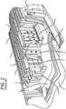
- Prior art Figure 1 schematically illustrates an exemplary ring furnace 100 having two parallel trains of sections (e.g ., 1-16) that are fluidly coupled by a crossover to form a ring furnace (it should be noted that the preheat, firing, and cooling zones rotate around the furnace). As the firing zone advances, anodes are removed and added in sections in advance of the firing zone to so allow continuous operation of the furnace runs. In the bake furnace 100 of Prior Art Figure 1 , there are two firing zones 120 moving in counter clockwise direction with each advance. An advance increments the process one section at a time around the furnace.
- the firing frame 122 (only one labeled), draft frames 131 and 131', preheat zones 130, cooling zones 110, preheat (exhaust) manifold 132, and cooling manifold 112 advance around the ring furnace with the firing zones.
- Stationary parts of the furnace are the crossover 140 and common collection exhaust side main 150 as well as the sections, flues, and walls.
- Each train has a pre-heating zone 130 and 130' with a firing zone 120 and 120', one or more firing frames 122 (only one is labeled), and cooling zone 110 and 110', respectively.
- Crossover 140 connects the trains and exhaust gas from preheat (exhaust) manifolds 132 and 132' is delivered to common exhaust collection conduit 150.
- Coupled to is intended to include both direct coupling (in which two elements that are coupled to each other contact each other) and indirect coupling (in which at least one additional element is located between the two elements). Therefore, the terms “coupled to” and “coupled with” are used synonymously.
- the particular number of wall elements in the preheat, firing, and cooling zones can vary considerably and will generally depend on furnace design and operation.
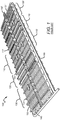
- FIG. 1 depicts within the pit that is formed by two adjacent wall elements anodes (in light grey) and packing coke (in dark grey).
- the wall elements 2 include an internal flue channel within which the combustion gases move from one wall element/zone to another via fluid coupling through openings (at 5) in the headwall 4 of the wall elements. Circulation of the hot gases is schematically indicated with the numeral 5.
- multiple wall elements 2 form multiple pits of a single section 3 within a zone and help convey heated gases from one section to another and one zone to another.
- the sections and flues are typically contained within a concrete tub 6 that is lined with thermal insulation 7. Movement of the draft frame, the firing frames, the exhaust manifold, and cooling manifold is typically manually performed or in an at least partially automated manner. Fire control is performed in either semi automated or fully automated manner using a computer to control the process (not shown).
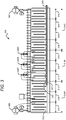
- FIG. 3 exemplarily shows a schematic of a carbon baking heat recovery ring furnace 300 according to the inventive subject matter.
- the furnace comprises a number of wall elements 310, each having an internal flue channel 312.
- the wall elements are then fluidly coupled to each other such that the internal flue channels form a continuous flow path as illustrated in Prior Art Figure 2 .
- the continuous path forms in sequence, a pre-heat zone 310P, a firing zone 310F having first, second, and terminal firing frames 330A, 330B, and 330T, respectively, and a cooling zone 310C.
- the preheat zone 310P comprises three distinct sections that are fluidly and thermally coupled to each other. The temperature of these sections (from left to right) is typically 200-600 °C, 600-850 °C, and 850-1050 °C, respectively, while the firing zone 310F has three sections with temperatures of about 1050-1200 °C in each zone.
- a cooling zone 310C that includes four sections with decreasing temperatures of 1050-1200 °C, 1075-1150 °C, 900-1075 °C, and 800-900 °C, respectively.
- the exact number of sections may vary considerably.
- a bypass conduit 320 is in direct heat exchange with the hot cooling air flowing through the internal flue channel and has a plurality of gates 322 (not all gates shown) to so allow fluidly coupling of the flue channel of the cooling zone with the flue channel of the firing zone and/or pre-heat zone.
- a portion of heated cooling air stream flowing in the flue channel of the cooling zone can be directly delivered to the firing and/or pre-heat zone.
- the gates fluidly are placed in the bypass conduit such that each of the wall elements can provide or receive air from the bypass conduit in at least one position.
- a bypass conduit can be configured that will receive heated cooling air from the flue channel in at least one wall element of the cooling zone and that will deliver the heated cooling air to the flue channel of at least one other wall element in the firing zone and/or preheat zone.
- the bypass conduit and/or the gates are configured (or operable) such as to allow flow of a portion of the heated cooling air stream without substantially moving the zero point in the ring furnace during firing operation.
- the cooling manifold 340 is coupled to a blower, booster, or other fan to so deliver ambient air to the internal flue channel, most typically via a cooling manifold.
- the pressure at the delivery point of the ambient air to the internal flue channel is relatively high and decreases as the air flows through the tortuous path within the wall elements of the cooling zone.
- an exhaust manifold 350 is coupled to a draft fan or other device (and draft frame) to so produce a negative pressure in the pre-heating zone and firing zone.
- the zero point 302 is thus the location at which the pressure is at about ambient pressure. It should be noted that movement of the zero point during firing operation from such position may adversely affect operation. For example, if the zero point moves into the firing zone, serious difficulties may arise due to the positive pressure at the fuel injection site. On the other hand, if the zero point substantially moves into the cooling zone, preheating and cooling may be adversely affected.
- a bypass conduit can be implemented that allows delivery of sufficient quantities of a heated cooling air stream from the positive pressure environment of the cooling zone directly to the negative pressure environment of the internal flue channels of the firing and/or preheat zone to reduce fuel gas consumption and increase combustion efficiency without substantially moving the zero point during firing operation.
- the zero point will remain during firing operation within the same wall element, and even within the same location within the same wall element.
- the quantity of the bypass stream i.e., the portion of the heated cooling air stream flowing through the bypass conduit
- the portion of the heated cooling air stream flowing through the bypass conduit will be between about 5-15 vol%, more typically between 5-25 vol%, even more typically between 15-35 vol%, and most typically between about 20-40 vol%.
- temperature control can be significantly fine tuned by use of proper selection and degree of opening of the gates. For example, where high temperature recycling is desired, the gates closest to (but not in) the firing zone will be opened. On the other hand, where less heat is required, a mixture of heated cooling air can be withdrawn from different wall elements in the cooling section, or from wall elements more distant from the firing section. Similarly, it should be recognized that the site of delivery of the heated cooling air may vary considerably, and that the choice is primarily dictated by the particular process and materials in the furnace. Thus, delivery is contemplated to the firing zone as well as to the preheat zone, or both. However, in especially preferred aspects of the inventive subject matter, the bypass stream is delivered to a position downstream of a first firing frame in the firing zone, and even more typically at or at or downstream of a terminal firing frame in the firing zone.
- bypass stream effectively provides recovered waste heat to the firing zone and/or preheat zone in an amount effective to reduce fuel demand, which allows oxygen otherwise used in the combustion of fuel now to participate in the combustion of the pitch and volatiles.
- the bypass stream will also provide additional oxygen to the firing zone and/or preheat zone thus further assisting in the combustion processes.
- the bypass conduit is configured/fluidly coupled to a section of the cooling zone where the heated cooling air has a temperature of between 1150-1200 °C, 1100-1150 °C, 1050-1100 °C, 1000-1050 °C, 950-1000 °C, 900-950 °C, and/or 800-900 °C.
- control over the gates on the bypass conduit may be used not only for temperature control, but also for combustion control, and control of the preheating temperatures or temperature gradient. Additionally, the gates and bypass conduit may also be used to maintain or change a pressure gradient in the ring furnace, and to control the location of the zero point where significant quantities of a bypass stream are being used. Most typically, control of the gates is performed in an automated or semi-automated fashion using a control circuit for opening and/or closing the gates. For example, automated or semi-automated operation is preferred when the firing frame and manifolds are being moved. However, manual operation is also deemed suitable for use herein.
- auxiliary bypass conduits may be generated by actuating the gates such that a desired heat distribution and/or temperature or pressure gradient can be achieved within a single zone (e.g., within the firing zone and/or preheat zone).
- one or more pressure control devices may be coupled to the bypass conduit and/or gates to so allow moving a bypass stream in a desired direction and/or at a desired rate.
- the direction may be opposite to the direction of the flue gas moving through the internal channel and the rate may be higher or lower than the flow rate of the flue gas moving through the internal channel.
- the bypass conduit is an internal conduit.
- the conduit may be formed as an integral part of a wall element, or may be added to the wall element, and may be at least partially disposed within the flue channel of the wall elements.
- the bypass conduit may also be at least in part external to the wall element.
- the conduit is located in, at, or near the sides or even bottom of the wall elements, and that the conduit will be covered by insulating material normally covering the wall elements.
- a heat transfer solution e.g., molten salt solution, oils, etc.
- more than one bypass conduit may be provided or formed to allow for even more process control.
- a method of reducing energy consumption of a ring furnace will include a step of operating a plurality of gates to configure a bypass conduit such that a portion of a heated cooling air stream in the flue channel of the cooling zone is directly delivered (rather than via a burner or firing frame) to the firing zone and/or pre-heat zone.
- the bypass conduit and the gates are configured such as to allow delivery of the portion of the heated cooling air stream to the firing zone and/or pre-heat zone at about an operating pressure present in the cooling zone and without substantially moving a zero point in the ring furnace.
- the gates, the bypass conduit, and other components used in this method the same considerations as provided above apply and are not reiterated here.
- a method of reducing energy consumption of a ring furnace (having a pre-heat, firing, and cooling zone) will include a step of recycling heat energy from the cooling zone directly to the pre-heat zone and/or firing zone, wherein the heat energy is carried from the cooling zone to the pre-heat zone and/or firing zone by a portion of a heated cooling air stream flowing through cooling zone.
- a configurable recycling conduit is formed in or runs though a plurality of wall elements that make up the pre-heat zone, the firing zone, and the cooling zone, and that opening and/or closing of gates coupled to the conduit and the wall sections in the selected zones will so produce a bypass conduit that is operable throughout the entire furnace.
- a bypass conduit may be preformed and coupled to the desirable sections.
Landscapes
- Engineering & Computer Science (AREA)
- Mechanical Engineering (AREA)
- General Engineering & Computer Science (AREA)
- Environmental & Geological Engineering (AREA)
- Waste-Gas Treatment And Other Accessory Devices For Furnaces (AREA)
- Furnace Details (AREA)
- Tunnel Furnaces (AREA)
Claims (14)
- Ringkammerofen zum Backen von Kohlenstoff mit Wärmerückgewinnung (300), welcher umfasst:eine Anzahl von Wandelementen (310), von denen jedes einen inneren Abgaskanal (312) aufweist, wobei diese mehreren Wandelemente (310) strömungsmäßig dergestalt aneinander gekoppelt sind, dass diese inneren Abgaskanäle (312) einen kontinuierlichen Strömungskanal bilden, welcher nacheinander eine Vorheizzone (310P), eine Brennzone (310F) und eine Abkühlzone (312C) aufweist;eine Umgehungsleitung (320), welche strömungsmäßig an den Abgaskanal (312) der Abkühlzone (310C) und den Abgaskanal (312) von mindestens einer von beiden, der Brennzone (310F) und der Vorheizzone (310P), dergestalt angeschlossen ist, dass ein Teil des erhitzten Kühlluftstromes im Abgaskanal (312) der Abkühlzone (310C) direkt an mindestens eine von beiden, der Brennzone (310F) und der Vorheizzone (310P), abgegeben wird;eine Anzahl von Schiebern (322), welche an die Umgehungsleitung (320) angeschlossen sind, wobei diese Anzahl von Schiebern (322) und die Umgehungsleitung (320) so konfiguriert sind, dass das Strömen des Teils des erhitzten Kühlluftstromes ermöglicht wird, ohne dass ein Nullpunkt im Ringofen (300) durchlaufen wird.
- Ringkammerofen zum Backen von Kohlenstoff mit Wärmerückgewinnung (300) nach Anspruch 1, bei welchem die Umgehungsleitung (320) innerhalb eines Wandabschnitts der Anzahl von Wandelementen (310) ausgebildet ist oder bei welchem ein Teil der Umgehungsleitung (320) sich außerhalb der Anzahl von Wandelementen (310) befindet.
- Ringkammerofen zum Backen von Kohlenstoff mit Wärmerückgewinnung (300) nach Anspruch 1, bei welchem die mehreren Schieber so konfiguriert sind, dass sie die Abgabe des erhitzen Kühlluftstromes in mehrere und unterschiedliche Wandelemente (310) von mindestens einer von beiden, der Brennzone (310F) und der Vorheizzone (310P), ermöglichen.
- Ringkammerofen zum Backen von Kohlenstoff mit Wärmerückgewinnung (300) nach Anspruch 1, welcher außerdem ein Steuerungssystem aufweist, welches so konfiguriert ist, dass die mehreren Schieber (322) dergestalt automatisch arbeiten, dass sich eine Position der Umgehungsleitung (320) ändert, während ein Brennrahmen in der Brennrichtung bewegt wird.
- Ringkammerofen zum Backen von Kohlenstoff mit Wärmerückgewinnung (300) nach Anspruch 1, bei welchem die Umgehungsleitung (320) und die mehreren Schieber (322) so konfiguriert sind, dass sie den Teil des erhitzten Kühlluftstromes an eine abströmseitige Position eines ersten Brennrahmens in der Brennzone (310F) abgeben, oder bei welchem die Umgehungsleitung (320) und die mehreren Schiebern (322) so konfiguriert sind, dass sie den Teil des erhitzten Kühlluftstromes an eine Position an einem endständigen Brennrahmen in der Brennzone (310F) oder an die Abströmseite eines solchen abgeben, oder
bei welchem die Umgehungsleitung (320) und die mehreren Schieber (322) so konfiguriert sind, dass sie den Teil des erhitzten Kühlluftstromes an mindestens eine von beiden, der Brennzone (310F) und der Vorheizzone (310P), bei dem in der Abkühlzone (310F) herrschenden Betriebsdruck abgeben. - Verfahren zur Senkung des Energieverbrauchs eines Ringkammerofens (300), welcher eine Vorheizzone (310P), eine Brennzone (310F) und eine Abkühlzone (310F) aufweist, wobei dieses Verfahren umfasst:die Rückführung von Wärmeenergie von der Abkühlzone (310C) direkt zu mindestens einer von beiden, der Brennzone (310F) und der Vorheizzone (310P), wobei die Wärmeenergie von der Abkühlzone (310C) zu der mindestens einen von beiden, der Vorheizzone (310P) und der Brennzone (310F), durch einen Teil des erhitzten Kühlluftstromes transportiert wird, welcher durch die Abkühlzone (310C) strömt, ohne einen Nullpunkt im Ringkammerofen (300) zu durchlaufen.
- Verfahren nach Anspruch 6, bei welchem der Schritt der Rückführung unter Verwendung einer konfigurierbaren Leitung erfolgt, welche in einer Anzahl von Wandelementen (310) ausgebildet ist oder durch diese hindurch verläuft, welche die Vorheizzone (310P), die Brennzone (310F) und die Abkühlzone (310C) ausmachen.
- Verfahren nach Anspruch 6, bei welchem der Teil des erhitzten Kühlluftstromes bei dem in der Abkühlzone (310C) herrschenden Betriebsdruck abgegeben wird oder bei welchem der Teil des erhitzten Kühlluftstromes zwischen 5 % und 35 % des erhitzten Kühlluftstromes liegt.
- Verfahren nach Anspruch 6, bei welchem außerdem der Ringkammerofen (300) eine Anzahl von Wandelementen (310) aufweist, von denen jedes einen inneren Abgaskanal aufweist, wobei diese mehreren Wandelemente (310) strömungsmäßig dergestalt aneinander gekoppelt sind, dass die inneren Abgaskanäle (312) einen kontinuierlichen Strömungskanal bilden, so dass nacheinander die Vorheizzone (310P), die Brennzone (310F) und die Abkühlzone (312C) entstehen, wobei dieses Verfahren außerdem umfasst:das Betätigen einer Anzahl von Schiebern (322), um eine Umgehungsleitung (320) dergestalt zu konfigurieren, dass ein Teils des erhitzten Kühlluftstromes im Abgaskanal (312) der Abkühlzone (310C) direkt an mindestens eine von beiden, der Brennzone (310F) und der Vorheizzone (310P), abgegeben wird; undbei welchem die Umgehungsleitung (320) und die mehreren Schieber (322) dergestalt konfiguriert sind, dass die Abgabe des Teils des erhitzen Kühlluftstromes an mindestens eine von beiden, der Brennzone (310F) und der Vorheizzone (310P), bei dem in der Abkühlzone (310C) herrschenden Druck ermöglicht wird, ohne dass ein Nullpunkt in dem Ringkammerofen (300) durchlaufen wird.
- Verfahren nach Anspruch 9, bei welchem die mehreren Schieber (322) an die mehreren Wandelemente (310) angeschlossen sind und bei welchem die Umgehungsleitung (320) innerhalb eines Wandabschnitts der mehreren Wandelemente (310) ausgebildet ist.
- Verfahren nach Anspruch 9, bei welchem der Teil des erhitzten Kühlluftstromes eine Temperatur von mindestens 1000 °C aufweist.
- Verfahren nach Anspruch 9, bei welchem der Teil des erhitzten Kühlluftstromes zwischen 5 % und 35 % des erhitzten Kühlluftstromes liegt.
- Verfahren nach Anspruch 9, bei welchem der Teil des erhitzten Kühlluftstromes an eine Position an einem endständigen Brennrahmen in der Brennzone (310F) oder auf dessen Abströmseite abgegeben wird oder bei welchem der Teil des erhitzten Kühlluftstromes an die Brennzone (310F) und die Vorheizzone (310P) abgegeben wird
- Verfahren nach Anspruch 9, bei welchem mindestens ein Teil der Umgehungsleitung (320) sich außerhalb der mehreren Wandelemente (310) befindet.
Applications Claiming Priority (2)
| Application Number | Priority Date | Filing Date | Title |
|---|---|---|---|
| US201261660452P | 2012-06-15 | 2012-06-15 | |
| PCT/US2013/030282 WO2013187959A1 (en) | 2012-06-15 | 2013-03-11 | Carbon baking heat recovery ring furnace |
Publications (3)
| Publication Number | Publication Date |
|---|---|
| EP2861925A1 EP2861925A1 (de) | 2015-04-22 |
| EP2861925A4 EP2861925A4 (de) | 2016-01-20 |
| EP2861925B1 true EP2861925B1 (de) | 2018-01-31 |
Family
ID=49756216
Family Applications (1)
| Application Number | Title | Priority Date | Filing Date |
|---|---|---|---|
| EP13804760.0A Not-in-force EP2861925B1 (de) | 2012-06-15 | 2013-03-11 | Ringkammerofen zum brennen von kohlenstoff mit wärmerückgewinnung |
Country Status (4)
| Country | Link |
|---|---|
| US (1) | US9970710B2 (de) |
| EP (1) | EP2861925B1 (de) |
| CA (1) | CA2876837C (de) |
| WO (1) | WO2013187959A1 (de) |
Families Citing this family (2)
| Publication number | Priority date | Publication date | Assignee | Title |
|---|---|---|---|---|
| DE102009046937B4 (de) * | 2009-11-20 | 2019-12-05 | Innovatherm Prof. Dr. Leisenberg Gmbh + Co. Kg | Verfahren und Vorrichtung zur Herstellung von Anoden |
| CN107448959B (zh) * | 2017-08-03 | 2019-04-19 | 中国环境科学研究院 | 一种碳素行业废气梯度与循环利用的减排系统与方法 |
Family Cites Families (20)
| Publication number | Priority date | Publication date | Assignee | Title |
|---|---|---|---|---|
| GB116455A (en) | 1917-11-07 | 1918-06-13 | Robert Karl Wehner | Improvements in Ovens or Furnaces for use in Baking Carbon Electrodes and for other purposes. |
| US3142482A (en) | 1961-03-21 | 1964-07-28 | Great Lakes Carbon Corp | Carbon body baking furnace |
| SE364729B (de) * | 1972-11-06 | 1974-03-04 | Graenges Eng Ab | |
| DE2364650A1 (de) * | 1973-12-24 | 1975-06-26 | Kloeckner Humboldt Deutz Ag | Verfahren zur waermebehandlung von koernigem und/oder stueckigem gut, insbesondere zum brennen von kalk, dolomit, magnesit oder dergleichen und schachtofen zur durchfuehrung des verfahrens |
| IT1073727B (it) | 1976-05-05 | 1985-04-17 | Elettrocarbonium Spa | Perfezionamento nei forni continui ad anello per la cottura o ricottura di materiali carboniosi |
| JPS53104610A (en) | 1977-02-08 | 1978-09-12 | Shinagawa Refractories Co | Tunnel kilns for reheating carbonaceous material impregnated with tar and pitch |
| IT1114515B (it) | 1979-02-05 | 1986-01-27 | Elettrocarbonium Spa | Perfezionamento nella regolazione dei forni continui ad anello di tipo hoffmann |
| US4253823A (en) | 1979-05-17 | 1981-03-03 | Alcan Research & Development Limited | Procedure and apparatus for baking carbon bodies |
| CA1260868A (en) | 1984-04-11 | 1989-09-26 | Izaak Lindhout | Process for calcining green coke |
| US4767320A (en) * | 1987-10-29 | 1988-08-30 | Chugai Ro Co., Ltd. | Automatically flow controlled continuous heat treating furnace |
| WO1991019147A1 (en) | 1990-05-29 | 1991-12-12 | Alcoa Of Australia Limited | Method and apparatus for control of carbon baking furnaces |
| NO174364C (no) | 1991-11-06 | 1994-04-20 | Norsk Hydro As | Anordning ved ringkammerovn |
| US5682631A (en) | 1995-08-04 | 1997-11-04 | Hill-Rom, Inc. | Bed having a reduced-shear pivot and step deck combination |
| AU3300697A (en) | 1997-06-04 | 1998-12-21 | Rodney D. Zabreznik | Production of heat-treated carbon bodies |
| US6436335B1 (en) | 1997-08-25 | 2002-08-20 | Innovatherm Prof. Dr. Leisenberg Gmbh & Co. Kg | Method for controlling a carbon baking furnace |
| FR2777072B1 (fr) | 1998-04-03 | 2000-05-19 | Pechiney Aluminium | Procede et dispositif de regulation des fours de cuisson a feu tournant |
| NO314104B1 (no) | 2001-06-06 | 2003-01-27 | Norsk Hydro As | Fremgangsmåte for å forbinde to rekker kamre i en ringkammerovn samt anordning ved samme |
| CH695870A5 (de) | 2002-09-23 | 2006-09-29 | R & D Carbon Ltd | Optimierung der Pechdampfverbrennung in einem Brennofen für Kohlenstoffelektroden. |
| EP1992895B1 (de) | 2007-05-14 | 2015-10-14 | Rio Tinto Alcan International Limited | Ringofen mit Brennvertiefungen mit hohem horizontalem Streckungsverhältnis und Verfahren zum Brennen von kohlehaltigen Artikeln darin |
| CN101606036B (zh) * | 2007-09-18 | 2011-12-28 | 德国伊诺瓦有限公司 | 热量回收方法及设备 |
-
2013
- 2013-03-11 US US13/794,448 patent/US9970710B2/en active Active
- 2013-03-11 WO PCT/US2013/030282 patent/WO2013187959A1/en not_active Ceased
- 2013-03-11 EP EP13804760.0A patent/EP2861925B1/de not_active Not-in-force
- 2013-03-11 CA CA2876837A patent/CA2876837C/en not_active Expired - Fee Related
Non-Patent Citations (1)
| Title |
|---|
| None * |
Also Published As
| Publication number | Publication date |
|---|---|
| US9970710B2 (en) | 2018-05-15 |
| WO2013187959A1 (en) | 2013-12-19 |
| CA2876837C (en) | 2020-06-30 |
| CA2876837A1 (en) | 2013-12-19 |
| US20130337391A1 (en) | 2013-12-19 |
| EP2861925A4 (de) | 2016-01-20 |
| EP2861925A1 (de) | 2015-04-22 |
Similar Documents
| Publication | Publication Date | Title |
|---|---|---|
| CA2876840C (en) | Carbon baking oxygen preheat and heat recovery firing system | |
| US11441078B2 (en) | Burn profiles for coke operations | |
| CN103702951B (zh) | 用于熔融玻璃的混合设施和方法 | |
| CN107075379B (zh) | 在次级加热室中具有改进的废气输送的炼焦炉 | |
| CN102517042B (zh) | 一种可控制多段燃烧的焦炉加热方法 | |
| CN104685029A (zh) | 经提供延长工艺周期的气体共用降低输出率的焦炉操作 | |
| EP2017558B1 (de) | Tunnelofen zum brennen von keramischen artikeln | |
| EP2861925B1 (de) | Ringkammerofen zum brennen von kohlenstoff mit wärmerückgewinnung | |
| CN101649378B (zh) | 利用钢板连续热处理炉进行低温回火热处理的方法 | |
| CN201495263U (zh) | 钢板连续热处理炉 | |
| CN105925276B (zh) | 一种焦炉燃烧室分段供气加热装置及其方法 | |
| CN213147379U (zh) | 铜锭燃气步进式加热炉加热段燃气燃烧机构 | |
| EP4571227A1 (de) | Sauerstoffverbrennungsofen für fritten und emaillen | |
| CN103667685B (zh) | 一种烧结点火炉煤气的串联预热方法及其系统 | |
| US20130108974A1 (en) | Carbon baking heat recovery firing system | |
| CN105112076B (zh) | 一种煤气直接加热的系统及方法 | |
| CN104833213B (zh) | 烧结点火炉用烘炉系统 | |
| JP2004131515A (ja) | 蓄熱式室式コークス炉の端フリュー加熱システム | |
| CA1079678A (en) | Battery of coke ovens with regenerative heat exchange | |
| CN204630380U (zh) | 烧结点火炉用烘炉系统 | |
| CN2807047Y (zh) | 有色金属熔化炉 | |
| KR20240098352A (ko) | 가열로 현열회수 시스템 |
Legal Events
| Date | Code | Title | Description |
|---|---|---|---|
| PUAI | Public reference made under article 153(3) epc to a published international application that has entered the european phase |
Free format text: ORIGINAL CODE: 0009012 |
|
| 17P | Request for examination filed |
Effective date: 20150114 |
|
| AK | Designated contracting states |
Kind code of ref document: A1 Designated state(s): AL AT BE BG CH CY CZ DE DK EE ES FI FR GB GR HR HU IE IS IT LI LT LU LV MC MK MT NL NO PL PT RO RS SE SI SK SM TR |
|
| AX | Request for extension of the european patent |
Extension state: BA ME |
|
| DAX | Request for extension of the european patent (deleted) | ||
| RA4 | Supplementary search report drawn up and despatched (corrected) |
Effective date: 20151223 |
|
| RIC1 | Information provided on ipc code assigned before grant |
Ipc: F27D 1/04 20060101ALI20151217BHEP Ipc: F27B 13/06 20060101ALI20151217BHEP Ipc: F27B 13/00 20060101AFI20151217BHEP Ipc: F27D 17/00 20060101ALI20151217BHEP Ipc: F27B 13/14 20060101ALI20151217BHEP |
|
| STAA | Information on the status of an ep patent application or granted ep patent |
Free format text: STATUS: EXAMINATION IS IN PROGRESS |
|
| 17Q | First examination report despatched |
Effective date: 20161124 |
|
| GRAP | Despatch of communication of intention to grant a patent |
Free format text: ORIGINAL CODE: EPIDOSNIGR1 |
|
| STAA | Information on the status of an ep patent application or granted ep patent |
Free format text: STATUS: GRANT OF PATENT IS INTENDED |
|
| INTG | Intention to grant announced |
Effective date: 20170905 |
|
| GRAS | Grant fee paid |
Free format text: ORIGINAL CODE: EPIDOSNIGR3 |
|
| GRAA | (expected) grant |
Free format text: ORIGINAL CODE: 0009210 |
|
| STAA | Information on the status of an ep patent application or granted ep patent |
Free format text: STATUS: THE PATENT HAS BEEN GRANTED |
|
| AK | Designated contracting states |
Kind code of ref document: B1 Designated state(s): AL AT BE BG CH CY CZ DE DK EE ES FI FR GB GR HR HU IE IS IT LI LT LU LV MC MK MT NL NO PL PT RO RS SE SI SK SM TR |
|
| REG | Reference to a national code |
Ref country code: GB Ref legal event code: FG4D Ref country code: CH Ref legal event code: EP |
|
| REG | Reference to a national code |
Ref country code: AT Ref legal event code: REF Ref document number: 967765 Country of ref document: AT Kind code of ref document: T Effective date: 20180215 |
|
| REG | Reference to a national code |
Ref country code: IE Ref legal event code: FG4D |
|
| REG | Reference to a national code |
Ref country code: DE Ref legal event code: R096 Ref document number: 602013032725 Country of ref document: DE |
|
| REG | Reference to a national code |
Ref country code: NL Ref legal event code: MP Effective date: 20180131 |
|
| REG | Reference to a national code |
Ref country code: LT Ref legal event code: MG4D |
|
| REG | Reference to a national code |
Ref country code: AT Ref legal event code: MK05 Ref document number: 967765 Country of ref document: AT Kind code of ref document: T Effective date: 20180131 |
|
| PG25 | Lapsed in a contracting state [announced via postgrant information from national office to epo] |
Ref country code: FI Free format text: LAPSE BECAUSE OF FAILURE TO SUBMIT A TRANSLATION OF THE DESCRIPTION OR TO PAY THE FEE WITHIN THE PRESCRIBED TIME-LIMIT Effective date: 20180131 Ref country code: HR Free format text: LAPSE BECAUSE OF FAILURE TO SUBMIT A TRANSLATION OF THE DESCRIPTION OR TO PAY THE FEE WITHIN THE PRESCRIBED TIME-LIMIT Effective date: 20180131 Ref country code: NL Free format text: LAPSE BECAUSE OF FAILURE TO SUBMIT A TRANSLATION OF THE DESCRIPTION OR TO PAY THE FEE WITHIN THE PRESCRIBED TIME-LIMIT Effective date: 20180131 Ref country code: NO Free format text: LAPSE BECAUSE OF FAILURE TO SUBMIT A TRANSLATION OF THE DESCRIPTION OR TO PAY THE FEE WITHIN THE PRESCRIBED TIME-LIMIT Effective date: 20180430 Ref country code: LT Free format text: LAPSE BECAUSE OF FAILURE TO SUBMIT A TRANSLATION OF THE DESCRIPTION OR TO PAY THE FEE WITHIN THE PRESCRIBED TIME-LIMIT Effective date: 20180131 Ref country code: ES Free format text: LAPSE BECAUSE OF FAILURE TO SUBMIT A TRANSLATION OF THE DESCRIPTION OR TO PAY THE FEE WITHIN THE PRESCRIBED TIME-LIMIT Effective date: 20180131 |
|
| PG25 | Lapsed in a contracting state [announced via postgrant information from national office to epo] |
Ref country code: IS Free format text: LAPSE BECAUSE OF FAILURE TO SUBMIT A TRANSLATION OF THE DESCRIPTION OR TO PAY THE FEE WITHIN THE PRESCRIBED TIME-LIMIT Effective date: 20180531 Ref country code: BG Free format text: LAPSE BECAUSE OF FAILURE TO SUBMIT A TRANSLATION OF THE DESCRIPTION OR TO PAY THE FEE WITHIN THE PRESCRIBED TIME-LIMIT Effective date: 20180430 Ref country code: RS Free format text: LAPSE BECAUSE OF FAILURE TO SUBMIT A TRANSLATION OF THE DESCRIPTION OR TO PAY THE FEE WITHIN THE PRESCRIBED TIME-LIMIT Effective date: 20180131 Ref country code: LV Free format text: LAPSE BECAUSE OF FAILURE TO SUBMIT A TRANSLATION OF THE DESCRIPTION OR TO PAY THE FEE WITHIN THE PRESCRIBED TIME-LIMIT Effective date: 20180131 Ref country code: SE Free format text: LAPSE BECAUSE OF FAILURE TO SUBMIT A TRANSLATION OF THE DESCRIPTION OR TO PAY THE FEE WITHIN THE PRESCRIBED TIME-LIMIT Effective date: 20180131 Ref country code: AT Free format text: LAPSE BECAUSE OF FAILURE TO SUBMIT A TRANSLATION OF THE DESCRIPTION OR TO PAY THE FEE WITHIN THE PRESCRIBED TIME-LIMIT Effective date: 20180131 Ref country code: GR Free format text: LAPSE BECAUSE OF FAILURE TO SUBMIT A TRANSLATION OF THE DESCRIPTION OR TO PAY THE FEE WITHIN THE PRESCRIBED TIME-LIMIT Effective date: 20180501 Ref country code: PL Free format text: LAPSE BECAUSE OF FAILURE TO SUBMIT A TRANSLATION OF THE DESCRIPTION OR TO PAY THE FEE WITHIN THE PRESCRIBED TIME-LIMIT Effective date: 20180131 |
|
| REG | Reference to a national code |
Ref country code: DE Ref legal event code: R119 Ref document number: 602013032725 Country of ref document: DE |
|
| PG25 | Lapsed in a contracting state [announced via postgrant information from national office to epo] |
Ref country code: EE Free format text: LAPSE BECAUSE OF FAILURE TO SUBMIT A TRANSLATION OF THE DESCRIPTION OR TO PAY THE FEE WITHIN THE PRESCRIBED TIME-LIMIT Effective date: 20180131 Ref country code: IT Free format text: LAPSE BECAUSE OF FAILURE TO SUBMIT A TRANSLATION OF THE DESCRIPTION OR TO PAY THE FEE WITHIN THE PRESCRIBED TIME-LIMIT Effective date: 20180131 Ref country code: RO Free format text: LAPSE BECAUSE OF FAILURE TO SUBMIT A TRANSLATION OF THE DESCRIPTION OR TO PAY THE FEE WITHIN THE PRESCRIBED TIME-LIMIT Effective date: 20180131 Ref country code: AL Free format text: LAPSE BECAUSE OF FAILURE TO SUBMIT A TRANSLATION OF THE DESCRIPTION OR TO PAY THE FEE WITHIN THE PRESCRIBED TIME-LIMIT Effective date: 20180131 |
|
| REG | Reference to a national code |
Ref country code: CH Ref legal event code: PL |
|
| PG25 | Lapsed in a contracting state [announced via postgrant information from national office to epo] |
Ref country code: MC Free format text: LAPSE BECAUSE OF FAILURE TO SUBMIT A TRANSLATION OF THE DESCRIPTION OR TO PAY THE FEE WITHIN THE PRESCRIBED TIME-LIMIT Effective date: 20180131 Ref country code: DK Free format text: LAPSE BECAUSE OF FAILURE TO SUBMIT A TRANSLATION OF THE DESCRIPTION OR TO PAY THE FEE WITHIN THE PRESCRIBED TIME-LIMIT Effective date: 20180131 Ref country code: SK Free format text: LAPSE BECAUSE OF FAILURE TO SUBMIT A TRANSLATION OF THE DESCRIPTION OR TO PAY THE FEE WITHIN THE PRESCRIBED TIME-LIMIT Effective date: 20180131 Ref country code: SM Free format text: LAPSE BECAUSE OF FAILURE TO SUBMIT A TRANSLATION OF THE DESCRIPTION OR TO PAY THE FEE WITHIN THE PRESCRIBED TIME-LIMIT Effective date: 20180131 Ref country code: CZ Free format text: LAPSE BECAUSE OF FAILURE TO SUBMIT A TRANSLATION OF THE DESCRIPTION OR TO PAY THE FEE WITHIN THE PRESCRIBED TIME-LIMIT Effective date: 20180131 |
|
| PLBE | No opposition filed within time limit |
Free format text: ORIGINAL CODE: 0009261 |
|
| STAA | Information on the status of an ep patent application or granted ep patent |
Free format text: STATUS: NO OPPOSITION FILED WITHIN TIME LIMIT |
|
| REG | Reference to a national code |
Ref country code: BE Ref legal event code: MM Effective date: 20180331 |
|
| GBPC | Gb: european patent ceased through non-payment of renewal fee |
Effective date: 20180430 |
|
| REG | Reference to a national code |
Ref country code: IE Ref legal event code: MM4A |
|
| PG25 | Lapsed in a contracting state [announced via postgrant information from national office to epo] |
Ref country code: LU Free format text: LAPSE BECAUSE OF NON-PAYMENT OF DUE FEES Effective date: 20180311 |
|
| 26N | No opposition filed |
Effective date: 20181102 |
|
| PG25 | Lapsed in a contracting state [announced via postgrant information from national office to epo] |
Ref country code: DE Free format text: LAPSE BECAUSE OF NON-PAYMENT OF DUE FEES Effective date: 20181002 Ref country code: IE Free format text: LAPSE BECAUSE OF NON-PAYMENT OF DUE FEES Effective date: 20180311 |
|
| PG25 | Lapsed in a contracting state [announced via postgrant information from national office to epo] |
Ref country code: LI Free format text: LAPSE BECAUSE OF NON-PAYMENT OF DUE FEES Effective date: 20180331 Ref country code: SI Free format text: LAPSE BECAUSE OF FAILURE TO SUBMIT A TRANSLATION OF THE DESCRIPTION OR TO PAY THE FEE WITHIN THE PRESCRIBED TIME-LIMIT Effective date: 20180131 Ref country code: BE Free format text: LAPSE BECAUSE OF NON-PAYMENT OF DUE FEES Effective date: 20180331 Ref country code: GB Free format text: LAPSE BECAUSE OF NON-PAYMENT OF DUE FEES Effective date: 20180430 Ref country code: CH Free format text: LAPSE BECAUSE OF NON-PAYMENT OF DUE FEES Effective date: 20180331 |
|
| PG25 | Lapsed in a contracting state [announced via postgrant information from national office to epo] |
Ref country code: FR Free format text: LAPSE BECAUSE OF NON-PAYMENT OF DUE FEES Effective date: 20180331 |
|
| PG25 | Lapsed in a contracting state [announced via postgrant information from national office to epo] |
Ref country code: MT Free format text: LAPSE BECAUSE OF NON-PAYMENT OF DUE FEES Effective date: 20180311 |
|
| PG25 | Lapsed in a contracting state [announced via postgrant information from national office to epo] |
Ref country code: TR Free format text: LAPSE BECAUSE OF FAILURE TO SUBMIT A TRANSLATION OF THE DESCRIPTION OR TO PAY THE FEE WITHIN THE PRESCRIBED TIME-LIMIT Effective date: 20180131 |
|
| PG25 | Lapsed in a contracting state [announced via postgrant information from national office to epo] |
Ref country code: PT Free format text: LAPSE BECAUSE OF FAILURE TO SUBMIT A TRANSLATION OF THE DESCRIPTION OR TO PAY THE FEE WITHIN THE PRESCRIBED TIME-LIMIT Effective date: 20180131 |
|
| PG25 | Lapsed in a contracting state [announced via postgrant information from national office to epo] |
Ref country code: HU Free format text: LAPSE BECAUSE OF FAILURE TO SUBMIT A TRANSLATION OF THE DESCRIPTION OR TO PAY THE FEE WITHIN THE PRESCRIBED TIME-LIMIT; INVALID AB INITIO Effective date: 20130311 Ref country code: MK Free format text: LAPSE BECAUSE OF NON-PAYMENT OF DUE FEES Effective date: 20180131 Ref country code: CY Free format text: LAPSE BECAUSE OF FAILURE TO SUBMIT A TRANSLATION OF THE DESCRIPTION OR TO PAY THE FEE WITHIN THE PRESCRIBED TIME-LIMIT Effective date: 20180131 |