EP2861897B2 - Slide ring seal - Google Patents
Slide ring seal Download PDFInfo
- Publication number
- EP2861897B2 EP2861897B2 EP14720469.7A EP14720469A EP2861897B2 EP 2861897 B2 EP2861897 B2 EP 2861897B2 EP 14720469 A EP14720469 A EP 14720469A EP 2861897 B2 EP2861897 B2 EP 2861897B2
- Authority
- EP
- European Patent Office
- Prior art keywords
- slide ring
- ring
- spring means
- seal according
- ring seal
- Prior art date
- Legal status (The legal status is an assumption and is not a legal conclusion. Google has not performed a legal analysis and makes no representation as to the accuracy of the status listed.)
- Active
Links
- 238000007789 sealing Methods 0.000 claims description 55
- 239000000428 dust Substances 0.000 claims description 20
- 230000006735 deficit Effects 0.000 claims description 3
- 238000002485 combustion reaction Methods 0.000 claims description 2
- 238000005461 lubrication Methods 0.000 claims 1
- 230000000284 resting effect Effects 0.000 description 10
- 230000002093 peripheral effect Effects 0.000 description 8
- 229920001971 elastomer Polymers 0.000 description 4
- 239000000806 elastomer Substances 0.000 description 4
- 238000004519 manufacturing process Methods 0.000 description 4
- 239000000463 material Substances 0.000 description 4
- 239000002245 particle Substances 0.000 description 4
- 230000015572 biosynthetic process Effects 0.000 description 2
- 238000009434 installation Methods 0.000 description 2
- 230000013011 mating Effects 0.000 description 2
- 230000003746 surface roughness Effects 0.000 description 2
- 239000002966 varnish Substances 0.000 description 2
- 244000043261 Hevea brasiliensis Species 0.000 description 1
- 230000005540 biological transmission Effects 0.000 description 1
- 150000001875 compounds Chemical class 0.000 description 1
- 230000009760 functional impairment Effects 0.000 description 1
- 239000007788 liquid Substances 0.000 description 1
- 239000002184 metal Substances 0.000 description 1
- 229920003052 natural elastomer Polymers 0.000 description 1
- 229920001194 natural rubber Polymers 0.000 description 1
- 238000009304 pastoral farming Methods 0.000 description 1
- 229920000642 polymer Polymers 0.000 description 1
- 230000008439 repair process Effects 0.000 description 1
- 230000000717 retained effect Effects 0.000 description 1
- 230000003068 static effect Effects 0.000 description 1
Images


Classifications
-
- F—MECHANICAL ENGINEERING; LIGHTING; HEATING; WEAPONS; BLASTING
- F16—ENGINEERING ELEMENTS AND UNITS; GENERAL MEASURES FOR PRODUCING AND MAINTAINING EFFECTIVE FUNCTIONING OF MACHINES OR INSTALLATIONS; THERMAL INSULATION IN GENERAL
- F16J—PISTONS; CYLINDERS; SEALINGS
- F16J15/00—Sealings
- F16J15/16—Sealings between relatively-moving surfaces
- F16J15/34—Sealings between relatively-moving surfaces with slip-ring pressed against a more or less radial face on one member
- F16J15/36—Sealings between relatively-moving surfaces with slip-ring pressed against a more or less radial face on one member connected by a diaphragm or bellow to the other member
-
- F—MECHANICAL ENGINEERING; LIGHTING; HEATING; WEAPONS; BLASTING
- F16—ENGINEERING ELEMENTS AND UNITS; GENERAL MEASURES FOR PRODUCING AND MAINTAINING EFFECTIVE FUNCTIONING OF MACHINES OR INSTALLATIONS; THERMAL INSULATION IN GENERAL
- F16J—PISTONS; CYLINDERS; SEALINGS
- F16J15/00—Sealings
- F16J15/16—Sealings between relatively-moving surfaces
- F16J15/34—Sealings between relatively-moving surfaces with slip-ring pressed against a more or less radial face on one member
- F16J15/3464—Mounting of the seal
- F16J15/348—Pre-assembled seals, e.g. cartridge seals
Definitions
- the invention relates to a mechanical seal according to the preamble of claim 1.
- the invention is therefore based on the object of designing and developing a mechanical seal of the type mentioned in such a way that it has a particularly flexible sliding ring and/or counter ring after cost-effective and problem-free production.
- At least one sealing surface could have elevations or unevenness in the size between 1 ⁇ m to W, preferably in the size between 5 ⁇ m to W, particularly preferably in the size between 20 ⁇ m to W, most preferably in the size between 50 ⁇ m to W have, wherein the elevations or bumps do not include any surface roughness or gas grooves.
- the elevations or bumps are ultimately wave crests and troughs that occur when circulating on a sealing surface.
- surface roughness or gas grooves are not among the structures that influence the unevenness or waviness of the sliding ring and/or counter ring.
- the elevations or bumps could be designed as wave troughs and wave crests.
- the elevations or bumps are wave crests and troughs that occur when circulating on a sealing surface. Wavy seal rings and counter rings can therefore also be advantageously used.
- the elevations or bumps could have at least two high points and two low points, preferably three high points and three low points, particularly preferably four high points and four low points, on a sealing surface.
- the elevations or bumps are ultimately wave crests and troughs that occur when circulating on a sealing surface. Depending on the ripple, different numbers of wave crests and troughs can occur. This ripple can essentially be flattened.
- the elevations or bumps on at least one sealing surface can be at least partially deformed by the bellows-like spring means in such a way that no impairment of the function of the mechanical seal occurs during operation.
- the bellows-like spring means can apply a force to a sealing surface which essentially flattens its waviness. Complete leveling is also possible.
- the bellows-like spring means could rest on the slide ring with an annular stop area and be fixed to a housing with an annular connection area, the stop area and the connection area being connected to one another by at least one elastically deformable hinge area.
- This specific design gives the spring means a geometric shape, which allows it to be easily deflected and deformed in both the radial, torsional and axial directions. Nevertheless, sufficient stiffness can be achieved through the hinge area and a suitable choice of the stiffness of the elastomer Contact pressure can be exerted on the slide ring.
- the hinge area could be S-shaped in cross section. Such a hinge area is particularly light and can be easily deflected in the radial, torsional and axial directions.
- the bellows-like spring means is preferably made of a polymer, in particular an elastomer.
- the elastomer is particularly preferably a natural rubber or has one.
- the counter ring could be received by a support body which has an axial extension for pressing onto a shaft. This makes it possible to achieve a press fit between the support body and the shaft.
- a region of the extension could have a truncated cone-shaped cross-section such that the interior of the extension is conical to accommodate a shaft.
- the interior of the extension is essentially a hollow cylinder, which is adjoined by a frustoconical section.
- the conical shape of the interior makes it easier to insert the support body onto the shaft.
- the conical design allows shafts to be accommodated whose diameters exhibit slight fluctuations.
- the formation of a conical course ensures that an area does not rest on the shaft. As a result, deformations induced by a press fit are not passed on to the support body to the extent that the alignment of the counter ring is negatively influenced. During assembly, there are fewer positional errors of a mating ring, so that the mechanical seal becomes very robust. Since the conical course ensures decoupling, high overlaps and plastic deformations are permitted in a sheet.
- the support body can sit on the shaft in such a way that a sealing fit is provided without additional sealing aids.
- the sealing seat can be metal-tight. Plastic deformation allows leak channels to be safely closed.
- the quotient of a first circular ring surface on the slide ring, which faces the spring means, and a projected second circular ring surface, which extends between a stop area of the spring means on the slide ring and a connection area of the spring means on a housing, could be selected such that by changing the pressure (in a room 20, see Fig. 4 ) a second force acting axially in the direction of the sliding ring on the projected second annular surface is between 1% and 100,000%, preferably between 10% and 1000%, particularly preferably between 10% and 100%, of a first force, which is caused by a change in pressure (in a room 20, see Fig. 4 ) acts on the first circular ring surface axially in the direction of the counter ring.
- a second force acting axially in the direction of the sliding ring on the projected second annular surface is between 1% and 100,000%, preferably between 10% and 1000%, particularly preferably between 10% and 100%, of a first force, which is caused by a change in pressure (in a room 20, see
- the k factor is the so-called hydraulic load factor.
- the known mechanical seals can only be used to a limited extent under changing pressure conditions.
- a mechanical seal which has a very low k-factor, can also withstand changing pressure conditions and seal securely against them. Much higher percentage values are also conceivable as an upper limit, which the person skilled in the art can find suitable based on this description.
- the spring means could have a radial lip resting on the sliding ring, which has an inner diameter of the same size or larger than the support body.
- the radial lip is preferably made of the same material and in one piece with the spring means. This can prevent dirt from getting into the area of the sealing surfaces.
- the spring means could have a radial lip resting on the sliding ring, which has the same inner diameter as the support body. This specific design ensures that the radial lip rests against the outer circumferential surface of a shaft and ensures that almost no particles can get into the area of the sealing surfaces.
- the spring means could have a radial lip, which protrudes from the slide ring at an angle and has an inner diameter that is the same size or larger than the support body. Due to the formation of an angle, the radial lip is easily deformable and can easily be pressed against the outer peripheral surface of a shaft.
- the spring means could have a radial lip, which protrudes from the slide ring to form an angle and has the same inner diameter as the support body. Such a radial lip rests against an outer circumferential surface of a shaft, so that almost no particles can pass through this radial lip.
- the spring means could have a dust lip resting on its stop area, which has an inner diameter of the same size or larger than the support body.
- the dust lip is not made of the same material as the spring means.
- the dust lip can be made of a nonwoven material, for example. Specifically, it is conceivable to provide a disk made of a fleece. A dust lip can prevent dust from getting into the area of the sealing surfaces.
- the spring means could have a dust lip resting on its stop area have which has the same inner diameter as the support body.
- This specific design ensures that the dust lip rests against the outer peripheral surface of a shaft. This specific design means that almost no dust can pass through the dust lip.
- the spring means could have a dust lip adjacent to its connection area, which has an inner diameter of the same size or larger than the support body.
- the spring means could have a dust lip adjacent to its connection area, which has the same inner diameter as the support body.
- This specific design makes it possible to realize an easily deformable and flexible dust lip, which in the normal state rests against the outer peripheral surface of a shaft.
- the spring means could be at least partially surrounded by a wall in the axial and/or radial direction. This creates a labyrinth seal.
- the wall could be part of a support body in which the counter ring is accommodated.
- This specific design means that no separate wall needs to be provided, but rather the support body can be pressed onto the shaft and at the same time form a labyrinth seal.
- a gap could be formed between the extension and the counter ring. Turbulences can form in the gap, which means that dirt particles are retained in the gap, but particle-free air can get between the sealing surfaces.
- the gap serves as a collecting channel for oil. Oil that has caught in the gap or the collecting channel can be returned by rotating the counter ring.
- the extension could extend so far in the axial direction that the sliding ring is also undercut by the extension. This specific design allows air to be advantageously guided between the sealing surfaces.
- the mechanical seal described here could be gas-lubricated. Surprisingly, it has been found that the mechanical seal functions using a gas despite the elevations or unevenness described here. The expert would have expected that the mechanical seal would only work well when using a liquid.
- the sealing surface of the sliding ring and/or the sealing surface of the counter ring could have hydrodynamic structures, in particular sickle-shaped structures. This improves the pressure build-up between the sealing surfaces. Structures of this type are in the EP 1 054 196 A2 disclosed. Against this background, it is also conceivable to provide hydrodynamic structures which are effective in both directions of rotation.
- the mechanical seal described here could be used to seal the crankshaft of internal combustion engines. It is particularly suitable for this because it has low friction.
- the mechanical seal described here can be used for gear seals at high sliding speeds and moderate pressures.
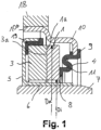
- Fig. 1 shows a mechanical seal, comprising a mechanical seal 1, which is mounted axially movably, and a counter ring 3, wherein the mechanical seal 1 and the counter ring 3 each have sealing surfaces 1a, 3a lying against one another, the sealing surface 1a of the mechanical ring 1 being the sealing surface 3a of the counter ring 3 is opposite and the sliding ring 1 is pressed against the counter ring 3 by a bellows-like spring means 4.
- Dm and s should be used in the same unit, for example in m.
- At least one sealing surface 1a, 3a has elevations or unevenness in the size of 0.1 ⁇ m to 500 ⁇ m.
- the counter ring 3 is received by a support body 5, which has an axial extension 6 for pressing onto a shaft 7.
- the elevations or bumps are designed as wave troughs and wave crests.
- the elevations or bumps on at least one sealing surface 1a, 3a can be at least partially deformed by the bellows-like spring means 4 in such a way that no functional impairment occurs during operation of the mechanical seal.
- the bellows-like spring means 4 rests on the slide ring 1 with an annular stop area 8 and is fixed to a housing 10 with an annular connection area 9, the stop area 8 and the connection area 9 being connected to one another by at least one elastically deformable hinge area 11.
- the hinge area 11 is S-shaped in cross section.
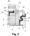
- Fig. 2 shows that the support body 5 with its axial extension 6 can be pressed onto the shaft 7.
- Fig. 3 shows that an area 6a of the extension 6 is designed in a truncated conical cross-section such that the interior of the extension 6 is conical to accommodate a shaft 7.
- the counter ring 3 is decoupled from forces that are introduced into the support body 5 by a press fit of the extension 6.
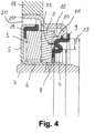
- Fig. 4 shows a mechanical seal in which a first annular surface 12 is formed on the sliding ring 1, on which a first force F1 can act in the axial direction, the first force F1 being directed in the direction of the counter ring 3.
- a projected, second annular surface 13 is provided.
- the projected, second annular surface 13 extends in the radial direction between a stop region 8 of the spring means 4 on the slide ring 1 and a connection region 9 of the spring means 4 on a housing 10.
- the second force F2 is between 1% and 100,000% of a first force F1, which acts on the first annular surface 12 axially in the direction of the counter ring 3.
- the first force F1 is advantageously greater than the second force F2.
- a pressure force acting on the sliding ring 1 can be compensated for by the spring means 4.
- the quotient of the first circular ring surface 12 on the slide ring 1, which faces the spring means 4, and the projected, second circular ring surface 13, which is between the stop area 8 of the spring means 4 on the slide ring 1 and the connection area 9 of the spring means 4 on the housing 10 extends, chosen in such a way that by changing the pressure in a space 20, the second force F2 acting axially in the direction of the sliding ring 1 on the projected, second annular surface 13 is between 1% and 100,000% of the first force F1, which is caused by changing the pressure in a space 20 acts on the first circular ring surface 12 axially in the direction of the counter ring 3.
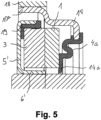
- Fig. 5 shows a mechanical seal in which the spring means 4a has a radial lip 14a resting on the sliding ring 1, which has a larger inner diameter than the support body 5 '.
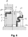
- Fig. 6 shows that the spring means 4b has a radial lip 14b resting on the sliding ring 1, which has the same inner diameter as the support body 5 '.
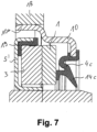
- Fig. 7 shows that the spring means 4c has a radial lip 14c, which protrudes from the slide ring 1 at an angle and has a larger inner diameter than the support body 5 '.
- Fig. 8 shows that the spring means 4d has a radial lip 14d, which protrudes from the slide ring 1 at an angle and has the same inner diameter as the support body 5 '.
- Fig. 9 shows that the spring means 4 has a dust lip 15a resting on its stop region 8, which has a larger inner diameter than the support body 5 '.
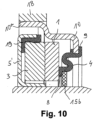
- Fig. 10 shows that the spring means 4 has a dust lip 15b resting on its stop area 8, which has the same inner diameter as the support body 5 '.
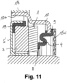
- Fig. 11 shows that the spring means 4 has a dust lip 15c resting on its connection area 9, which has a larger inner diameter than the support body 5 '.
- Fig. 12 shows that the spring means 4 has a dust lip 15d resting on its connection area 9, which has the same inner diameter as the support body 5 '.
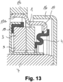
- Fig. 13 shows that the spring means 4 is at least partially surrounded by a wall 16 in the axial and/or radial direction. This results in a chambering of the spring means 4. A labyrinth seal is created.
- Fig. 14 shows that the wall 16a is part of a support body 5" in which the counter ring 3 is accommodated.
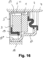
- Fig. 15 shows that a gap 17 is included between the extension 6'" and the counter ring 3.
- Fig. 16 shows the lower part of the mechanical seal according to Fig. 15 .
- the gap 17 functions here as a collecting channel for oil, which can be returned.
- Fig. 17 shows that the extension 6 extends so far in the axial direction that the sliding ring 1 is also undercut by the extension 6.
- the counter ring 3 is designed and/or arranged in such a way that rotational forces induce slight conicity or deformation. This applies to everyone in the Fig. 1 to 18 mechanical seals described.
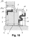
- Fig. 18 shows a mechanical seal in which an area 10a of the housing is applied to a counter wall 18 in a metal sealing manner, fully rubberized, partially rubberized or with the interposition of a sealing compound, in particular a sealing varnish.
- the counter ring 3 could be designed symmetrically so that centrifugal forces have no influence on its deformation.
- the extension 6 could be statically sealed relative to the shaft 7.
- the static seal can be fully rubberized, partially rubberized, with sealing varnish or have a metallic seal.
- a signal track 19 is assigned to the counter ring 3. This allows the mechanical seal to also function as an encoder.
- the signal track 19 can consist of an elastomer in which magnetizable or magnetized particles are accommodated.
- Fig. 19 shows the waviness of the sliding ring 1 as it rotates on its sealing surface 1a.
- the angle ⁇ takes values between 0 and 360 degrees.
- Fig. 19 It is shown that two high points and two low points are passed through when one runs around a sealing surface 1a.
- the elevations or bumps on a sealing surface 1a therefore have two high points and two low points, namely two wave crests and two wave troughs.
- the elevations or bumps on a sealing surface 1a, 3a can be at least partially deformed by the bellows-like spring means 4 in such a way that no impairment of the function of the mechanical seal occurs during operation.
Description
Die Erfindung betrifft eine Gleitringdichtung gemäß dem Oberbegriff des Patentanspruchs 1.The invention relates to a mechanical seal according to the preamble of
Aus der
Vor diesem Hintergrund besteht ein Bedarf nach Gleitringdichtungen, deren Gleitringe oder Gegenringe besonders flexibel sind, um problemlos Schwingungen auszugleichen.Against this background, there is a need for mechanical seals whose sliding rings or mating rings are particularly flexible in order to easily compensate for vibrations.
Der Erfindung liegt daher die Aufgabe zugrunde, eine Gleitringdichtung der eingangs genannten Art derart auszugestalten und weiterzubilden, dass diese nach kostengünstiger und problemloser Fertigung einen besonders flexiblen Gleitring und/oder Gegenring aufweist.The invention is therefore based on the object of designing and developing a mechanical seal of the type mentioned in such a way that it has a particularly flexible sliding ring and/or counter ring after cost-effective and problem-free production.
Die vorliegende Erfindung löst die zuvor genannte Aufgabe durch die Merkmale des Patentanspruchs 1.The present invention solves the aforementioned problem through the features of
Erfindungsgemäß weist mindestens eine Dichtfläche Erhebungen oder Unebenheiten in der Größe 0,1 µm bis W auf, wobei sich W nach der Formel ![]()
![]()
Der zuvor genannte Faktor 0,03 kann auch einen höheren Wert annehmen, den der Fachmann anhand dieser Beschreibung geeignet auffinden kann.The aforementioned factor 0.03 can also assume a higher value, which the person skilled in the art can find appropriate based on this description.
Vor diesem Hintergrund könnte mindestens eine Dichtfläche Erhebungen oder Unebenheiten in der Größe zwischen 1 µm bis W, bevorzugt in der Größe zwischen 5 µm bis W, besonders bevorzugt in der Größe zwischen 20 µm bis W, höchst bevorzugt in der Größe zwischen 50 µm bis W aufweisen, wobei die Erhebungen oder Unebenheiten keine Oberflächenrauheiten oder Gasnuten umfassen. Die Erhebungen oder Unebenheiten sind letztlich Wellenberge und Wellentäler, welche beim Umlaufen auf einer Dichtfläche auftreten. Insoweit zählen Oberflächenrauheiten oder Gasnuten nicht zu den Strukturen, welche die Unebenheit bzw. Welligkeit des Gleitrings und/ oder Gegenrings beeinflussen.Against this background, at least one sealing surface could have elevations or unevenness in the size between 1 µm to W, preferably in the size between 5 µm to W, particularly preferably in the size between 20 µm to W, most preferably in the size between 50 µm to W have, wherein the elevations or bumps do not include any surface roughness or gas grooves. The elevations or bumps are ultimately wave crests and troughs that occur when circulating on a sealing surface. In this respect, surface roughness or gas grooves are not among the structures that influence the unevenness or waviness of the sliding ring and/or counter ring.
Die Erhebungen oder Unebenheiten könnten als Wellentäler und Wellenberge ausgestaltet sein. Die Erhebungen oder Unebenheiten sind Wellenberge und Wellentäler, welche beim Umlaufen auf einer Dichtfläche auftreten. Vorteilhaft können daher auch wellige Gleitringe und Gegenringe verwendet werden.The elevations or bumps could be designed as wave troughs and wave crests. The elevations or bumps are wave crests and troughs that occur when circulating on a sealing surface. Wavy seal rings and counter rings can therefore also be advantageously used.
Die Erhebungen oder Unebenheiten könnten auf einer Dichtfläche mindestens zwei Hoch- und zwei Tiefpunkte, bevorzugt drei Hoch- und drei Tiefpunkte, besonders bevorzugt vier Hoch- und vier Tiefpunkte aufweisen. Die Erhebungen oder Unebenheiten sind letztlich Wellenberge und Wellentäler, welche beim Umlaufen auf einer Dichtfläche auftreten. Je nach Welligkeit können unterschiedlich viele Wellenberge und Wellentäler auftreten. Diese Welligkeit kann im Wesentlichen eingeebnet werden.The elevations or bumps could have at least two high points and two low points, preferably three high points and three low points, particularly preferably four high points and four low points, on a sealing surface. The elevations or bumps are ultimately wave crests and troughs that occur when circulating on a sealing surface. Depending on the ripple, different numbers of wave crests and troughs can occur. This ripple can essentially be flattened.
Die Erhebungen oder Unebenheiten auf mindestens einer Dichtfläche sind durch das balgartige Federmittel zumindest teilweise derart deformierbar, dass im Betrieb der Gleitringdichtung keine Funktionsbeeinträchtigung entsteht. Das balgartige Federmittel kann eine Kraft auf eine Dichtfläche anwenden, welche deren Welligkeit im Wesentlichen einebnet. Auch eine vollständige Einebnung ist möglich.The elevations or bumps on at least one sealing surface can be at least partially deformed by the bellows-like spring means in such a way that no impairment of the function of the mechanical seal occurs during operation. The bellows-like spring means can apply a force to a sealing surface which essentially flattens its waviness. Complete leveling is also possible.
Das balgartige Federmittel könnte mit einem ringförmigen Anschlagbereich am Gleitring anliegen und mit einem ringförmigen Anbindebereich an einem Gehäuse festgelegt sein, wobei der Anschlagbereich und der Anbindebereich durch mindestens einen elastisch deformierbaren Scharnierbereich aneinander angebunden sind. Durch diese konkrete Ausgestaltung wird dem Federmittel eine geometrische Form verliehen, welche erlaubt, dieses sowohl in radialer, torsionaler und axialer Richtung leicht auszulenken und zu deformieren. Dennoch kann durch den Scharnierbereich und eine geeignete Wahl der Steifigkeit des Elastomers eine ausreichende Anpresskraft auf den Gleitring ausgeübt werden. Vor diesem Hintergrund könnte der Scharnierbereich im Querschnitt S-förmig ausgebildet sein. Ein solcher Scharnierbereich ist besonders leicht und problemlos in radialer, torsionaler und axialer Richtung auslenkbar. Das balgartige Federmittel ist bevorzugt aus einem Polymer, insbesondere einem Elastomer, gefertigt. Besonders bevorzugt ist das Elastomer ein Naturkautschuk oder weist einen solchen auf.The bellows-like spring means could rest on the slide ring with an annular stop area and be fixed to a housing with an annular connection area, the stop area and the connection area being connected to one another by at least one elastically deformable hinge area. This specific design gives the spring means a geometric shape, which allows it to be easily deflected and deformed in both the radial, torsional and axial directions. Nevertheless, sufficient stiffness can be achieved through the hinge area and a suitable choice of the stiffness of the elastomer Contact pressure can be exerted on the slide ring. Against this background, the hinge area could be S-shaped in cross section. Such a hinge area is particularly light and can be easily deflected in the radial, torsional and axial directions. The bellows-like spring means is preferably made of a polymer, in particular an elastomer. The elastomer is particularly preferably a natural rubber or has one.
Der Gegenring könnte von einem Tragkörper aufgenommen sein, welcher einen axialen Fortsatz zum Aufpressen auf eine Welle aufweist. Hierdurch ist ein Presssitz zwischen Tragkörper und Welle realisierbar.The counter ring could be received by a support body which has an axial extension for pressing onto a shaft. This makes it possible to achieve a press fit between the support body and the shaft.
Ein Bereich des Fortsatzes könnte im Querschnitt derart kegelstumpfförmig ausgestaltet sein, dass der Innenraum des Fortsatzes zur Aufnahme einer Welle konisch verläuft. Der Innenraum des Fortsatzes ist im Wesentlichen ein Hohlzylinder, an den sich ein kegelstumpfförmiger Abschnitt anschließt. Durch den konischen Verlauf des Innenraums ist das Einführen des Tragkörpers auf die Welle erleichtert. Die konische Ausgestaltung erlaubt es, Wellen aufzunehmen, deren Durchmesser geringfügige Schwankungen aufweisen.A region of the extension could have a truncated cone-shaped cross-section such that the interior of the extension is conical to accommodate a shaft. The interior of the extension is essentially a hollow cylinder, which is adjoined by a frustoconical section. The conical shape of the interior makes it easier to insert the support body onto the shaft. The conical design allows shafts to be accommodated whose diameters exhibit slight fluctuations.
Durch die Ausbildung eines konischen Verlaufs ist sichergestellt, dass ein Bereich nicht auf der Welle aufliegt. Hierdurch werden durch einen Presssitz induzierte Verformungen an den Tragkörper nicht in dem Maße weitergegeben, dass die Ausrichtung des Gegenrings in negativer Weise beeinflusst wird. Bei einer Montage entstehen somit geringere Lagefehler eines Gegenrings, so dass die Gleitringdichtung sehr robust wird. Da der konische Verlauf für eine Entkopplung sorgt, sind hohe Überdeckungen und plastische Verformungen in einem Blech zulässig. Der Tragkörper kann derart auf der Welle aufsitzen, dass ein Dichtsitz ohne zusätzliche Dichthilfen gegeben ist. Der Dichtsitz kann metallisch dicht sein. Eine plastische Verformung erlaubt es, Leckagekanäle sicher abzuschließen.The formation of a conical course ensures that an area does not rest on the shaft. As a result, deformations induced by a press fit are not passed on to the support body to the extent that the alignment of the counter ring is negatively influenced. During assembly, there are fewer positional errors of a mating ring, so that the mechanical seal becomes very robust. Since the conical course ensures decoupling, high overlaps and plastic deformations are permitted in a sheet. The support body can sit on the shaft in such a way that a sealing fit is provided without additional sealing aids. The sealing seat can be metal-tight. Plastic deformation allows leak channels to be safely closed.
Der Quotient aus einer ersten Kreisringfläche am Gleitring, welche dem Federmittel zugewandt ist, und einer projizierten zweiten Kreisringfläche, welche sich zwischen einem Anschlagbereich des Federmittels am Gleitring und einem Anbindebereich des Federmittels an einem Gehäuse erstreckt, könnte derart gewählt sein, dass durch Druckänderung (in einem Raum 20, siehe
Zusätzlich kann mit dieser Anordnung bei einer Auslegung in sehr kleinem Bauraum Druckstabilität erreicht werden. Auch bei nicht wechselnder Druckbelastung kann ein geringer Bauraum genutzt werden.In addition, with this arrangement, pressure stability can be achieved when designed in a very small installation space. Even if the pressure load does not change, a small installation space can be used.
Die in den angegebenen Intervallen genannten Prozentwerte sind anwendungsspezifisch je nach abzudichtender Druckdifferenz geeignet auszuwählen. Eine Gleitringdichtung mit einem k-Faktor von ungefähr 0 kann somit einfach realisiert werden. Üblicherweise müssen Gleitringdichtungen k-Faktoren im Bereich von 0,6 bis 0,8 aufweisen, um gegen Druck sicher abzudichten.The percentage values stated in the specified intervals must be selected appropriately for the application depending on the pressure difference to be sealed. A mechanical seal with a k factor of approximately 0 can therefore be easily implemented. Typically, mechanical seals must have k factors in the range of 0.6 to 0.8 in order to seal reliably against pressure.
Der k-Faktor ist der sogenannte hydraulische Belastungsfaktor. Die bekannten Gleitringdichtungen sind jedoch nur begrenzt bei wechselnden Druckverhältnissen einsetzbar. Eine Gleitringdichtung, welche einen sehr geringen k-Faktor aufweist, kann auch wechselnden Druckverhältnissen Stand halten und gegen diese sicher abdichten. Es sind als Obergrenze auch noch weit höhere prozentuale Werte denkbar, die der Fachmann anhand dieser Beschreibung geeignet auffinden kann.The k factor is the so-called hydraulic load factor. However, the known mechanical seals can only be used to a limited extent under changing pressure conditions. A mechanical seal, which has a very low k-factor, can also withstand changing pressure conditions and seal securely against them. Much higher percentage values are also conceivable as an upper limit, which the person skilled in the art can find suitable based on this description.
Das Federmittel könnte eine am Gleitring anliegende Radiallippe aufweisen, welche einen gleich großen oder größeren Innendurchmesser aufweist als der Tragkörper. Bevorzugt ist die Radiallippe materialeinheitlich und einstückig mit dem Federmittel ausgebildet. Hierdurch kann Schmutz davon abgehalten werden, in den Bereich der Dichtflächen zu gelangen.The spring means could have a radial lip resting on the sliding ring, which has an inner diameter of the same size or larger than the support body. The radial lip is preferably made of the same material and in one piece with the spring means. This can prevent dirt from getting into the area of the sealing surfaces.
Vor diesem Hintergrund könnte das Federmittel eine am Gleitring anliegende Radiallippe aufweisen, welche den gleichen Innendurchmesser aufweist wie der Tragkörper. Durch diese konkrete Ausgestaltung ist sichergestellt, dass die Radiallippe streifend an der Außenumfangsfläche einer Welle anliegt und bewirkt, dass nahezu keine Partikel in den Bereich der Dichtflächen gelangen können.Against this background, the spring means could have a radial lip resting on the sliding ring, which has the same inner diameter as the support body. This specific design ensures that the radial lip rests against the outer circumferential surface of a shaft and ensures that almost no particles can get into the area of the sealing surfaces.
Das Federmittel könnte eine Radiallippe aufweisen, welche unter Winkelbildung vom Gleitring abragt und einen gleich großen oder größeren Innendurchmesser aufweist als der Tragkörper. Aufgrund der Winkelbildung ist die Radiallippe leicht deformierbar und kann problemlos gegen die Außenumfangsfläche einer Welle gedrückt werden.The spring means could have a radial lip, which protrudes from the slide ring at an angle and has an inner diameter that is the same size or larger than the support body. Due to the formation of an angle, the radial lip is easily deformable and can easily be pressed against the outer peripheral surface of a shaft.
Vor diesem Hintergrund könnte das Federmittel eine Radiallippe aufweisen, welche unter Winkelbildung vom Gleitring abragt und den gleichen Innendurchmesser aufweist wie der Tragkörper. Eine solche Radiallippe liegt streifend an einer Außenumfangsfläche einer Welle an, so dass nahezu keine Partikel diese Radiallippe passieren können.Against this background, the spring means could have a radial lip, which protrudes from the slide ring to form an angle and has the same inner diameter as the support body. Such a radial lip rests against an outer circumferential surface of a shaft, so that almost no particles can pass through this radial lip.
Das Federmittel könnte eine an seinem Anschlagbereich anliegende Staublippe aufweisen, welche einen gleich großen oder größeren Innendurchmesser aufweist als der Tragkörper. Die Staublippe ist nicht materialeinheitlich mit dem Federmittel ausgebildet. Die Staublippe kann beispielsweise aus einem Vliesstoff gefertigt sein. Konkret ist denkbar, eine Scheibe aus einem Vlies vorzusehen. Durch eine Staublippe kann verhindert werden, dass Staub in den Bereich der Dichtflächen gelangt.The spring means could have a dust lip resting on its stop area, which has an inner diameter of the same size or larger than the support body. The dust lip is not made of the same material as the spring means. The dust lip can be made of a nonwoven material, for example. Specifically, it is conceivable to provide a disk made of a fleece. A dust lip can prevent dust from getting into the area of the sealing surfaces.
Vor diesem Hintergrund könnte das Federmittel eine an seinem Anschlagbereich anliegende Staublippe aufweisen, welche den gleichen Innendurchmesser aufweist wie der Tragkörper. Durch diese konkrete Ausgestaltung ist sichergestellt, dass die Staublippe streifend an der Außenumfangsfläche einer Welle anliegt. Durch diese konkrete Ausgestaltung kann nahezu kein Staub die Staublippe passieren.Against this background, the spring means could have a dust lip resting on its stop area have which has the same inner diameter as the support body. This specific design ensures that the dust lip rests against the outer peripheral surface of a shaft. This specific design means that almost no dust can pass through the dust lip.
Das Federmittel könnte eine an seinem Anbindebereich anliegende Staublippe aufweisen, welche einen gleich großen oder größeren Innendurchmesser aufweist als der Tragkörper. Durch die Anbindung der Staublippe an den Anbindebereich ist die Staublippe leicht flexibel deformierbar, ohne dabei an das Federmittel anzuschlagen und dieses zu stören.The spring means could have a dust lip adjacent to its connection area, which has an inner diameter of the same size or larger than the support body. By connecting the dust lip to the connection area, the dust lip can be easily and flexibly deformed without hitting the spring means and disturbing it.
Vor diesem Hintergrund könnte das Federmittel eine an seinem Anbindebereich anliegende Staublippe aufweisen, welche den gleichen Innendurchmesser aufweist wie der Tragkörper. Durch diese konkrete Ausgestaltung ist eine leicht deformierbare und flexible Staublippe realisierbar, welche im Normalzustand streifend an der Außenumfangsfläche einer Welle anliegt.Against this background, the spring means could have a dust lip adjacent to its connection area, which has the same inner diameter as the support body. This specific design makes it possible to realize an easily deformable and flexible dust lip, which in the normal state rests against the outer peripheral surface of a shaft.
Das Federmittel könnte von einer Wandung zumindest teilweise in axialer und/oder radialer Richtung umgeben sein. Hierdurch ist eine Labyrinthdichtung realisiert.The spring means could be at least partially surrounded by a wall in the axial and/or radial direction. This creates a labyrinth seal.
Vor diesem Hintergrund könnte die Wandung ein Teil eines Tragkörpers sein, in welchem der Gegenring aufgenommen ist. Durch diese konkrete Ausgestaltung ist keine separate Wandung vorzusehen, sondern kann der Tragkörper auf die Welle aufgepresst werden und zugleich eine Labyrinthdichtung ausbilden.Against this background, the wall could be part of a support body in which the counter ring is accommodated. This specific design means that no separate wall needs to be provided, but rather the support body can be pressed onto the shaft and at the same time form a labyrinth seal.
Zwischen dem Fortsatz und dem Gegenring könnte ein Spalt ausgebildet sein. In dem Spalt können sich Verwirbelungen bilden, wodurch Schmutzpartikel im Spalt zurückgehalten werden, jedoch partikelfreie Luft zwischen die Dichtflächen gelangen kann.A gap could be formed between the extension and the counter ring. Turbulences can form in the gap, which means that dirt particles are retained in the gap, but particle-free air can get between the sealing surfaces.
Des Weiteren ist denkbar, dass der Spalt als Fangrinne für Öl dient. Öl, welches sich im Spalt bzw. der Fangrinne gefangen hat, kann durch die Rotation des Gegenrings rückgefördert werden.Furthermore, it is conceivable that the gap serves as a collecting channel for oil. Oil that has caught in the gap or the collecting channel can be returned by rotating the counter ring.
Der Fortsatz könnte sich in axialer Richtung derart weit erstrecken, dass auch der Gleitring vom Fortsatz unterlaufen ist. Durch diese konkrete Ausgestaltung kann Luft vorteilhaft zwischen die Dichtflächen geführt werden.The extension could extend so far in the axial direction that the sliding ring is also undercut by the extension. This specific design allows air to be advantageously guided between the sealing surfaces.
Die hier beschriebene Gleitringdichtung könnte gasgeschmiert sein. Überraschend hat sich herausgestellt, dass die Gleitringdichtung trotz der hier beschriebenen Erhebungen oder Unebenheiten unter Verwendung eines Gases funktioniert. Der Fachmann hätte erwartet, dass die Gleitringdichtung lediglich bei Verwendung einer Flüssigkeit gut arbeitet.The mechanical seal described here could be gas-lubricated. Surprisingly, it has been found that the mechanical seal functions using a gas despite the elevations or unevenness described here. The expert would have expected that the mechanical seal would only work well when using a liquid.
Die Dichtfläche des Gleitrings und/ oder die Dichtfläche des Gegenrings könnte hydrodynamische Strukturen, insbesondere sichelförmige Strukturen, aufweisen. Hierdurch wird der Druckaufbau zwischen den Dichtflächen verbessert. Strukturen dieser Art sind in der
Die hier beschriebene Gleitringdichtung könnte als Abdichtung der Kurbelwelle von Verbrennungsmotoren verwendet werden. Sie eignet sich hierfür besonders, da sie eine geringe Reibung zeigt.The mechanical seal described here could be used to seal the crankshaft of internal combustion engines. It is particularly suitable for this because it has low friction.
Die hier beschriebene Gleitringdichtung kann für Getriebeabdichtungen bei hohen Gleitgeschwindigkeiten und moderaten Drücken verwendet werden. Insbesondere ist denkbar, die Gleitringdichtung in der Automobilindustrie einzusetzen. Dabei ist konkret denkbar, die Gleitringdichtung als Turboladerabdichtung, Kurbelwellenabdichtung, Getriebeabdichtung oder Abdichtung von Elektromotoren zu verwenden.The mechanical seal described here can be used for gear seals at high sliding speeds and moderate pressures. In particular, it is conceivable to use the mechanical seal in the automotive industry. It is specifically conceivable to use the mechanical seal as a turbocharger seal, crankshaft seal, transmission seal or seal for electric motors.
Es ist möglich, die hier beschriebene Gleitringdichtung als gasgeschmierte Gleitringdichtung auszugestalten. Des Weiteren ist es möglich, die Dichtflächen mit hydrodynamisch wirksamen Strukturen zu versehen.It is possible to design the mechanical seal described here as a gas-lubricated mechanical seal. Furthermore, it is possible to provide the sealing surfaces with hydrodynamically effective structures.
In der Zeichnung zeigen
- Fig. 1
- eine Schnittansicht des oberen Teils einer Gleitringdichtung, wobei der Gegenring und der Gleitring derart flexibel sind, dass diese
Unebenheiten von - Fig. 2
- eine Gleitringdichtung, welche einen Tragkörper aufweist, der unter einem Presssitz auf einer Welle aufsitzt,
- Fig. 3
- eine teilweise Schnittansicht eines Tragkörpers, bei welchem etwa zwei Drittel seines Fortsatzes auf der Außenumfangsfläche einer Welle aufliegen und etwa ein Drittel des Fortsatzes sich unter Ausbildung eines konisch verlaufenden Ringspaltes von der Außenumfangsfläche abhebt,
- Fig. 4
- eine Gleitringdichtung, bei welcher Kreisringflächen dargestellt sind, an welchen Drucckräfte angreifen können,
- Fig. 5
- eine Gleitringdichtung, bei welcher eine Radiallippe parallel zu den Dichtflächen verläuft,
- Fig. 6
- eine weitere Gleitringdichtung, bei welcher eine etwas längere Radiallippe parallel zu den Dichtflächen verläuft,
- Fig. 7
- eine Gleitringdichtung, bei welcher eine Radiallippe derart gewinkelt ist, dass diese einen
von 90° verschiedenen Winkel mit der Rotationsachse der Welle einschließt, - Fig. 8
- eine Gleitringdichtung mit einer ebenfalls geneigten Radiallippe, welche streifend an einer Außenumfangsfläche einer Welle anliegt,
- Fig. 9
- eine Gleitringdichtung, bei welcher am Federmittel eine Vliesscheibe angeordnet ist,
- Fig. 10
- eine weitere Gleitringdichtung, bei welcher am Federmittel eine Vliesscheibe festgelegt ist, welche in streifendem Kontakt zur Außenumfangsfläche einer Welle steht,
- Fig. 11
- eine Gleitringdichtung, bei welcher eine Vliesscheibe vom Gleitring weit beabstandet ist,
- Fig. 12
- eine weitere Gleitringdichtung, bei welcher eine Vliesscheibe relativ weit vom Gleitring beabstandet ist, jedoch an der Außenumfangsfläche der Welle anliegt,
- Fig. 13
- eine Gleitringdichtung, bei welcher eine Labyrinthdichtung vorgesehen ist,
- Fig. 14
- eine weitere Gleitringdichtung, bei welcher eine Labyrinthdichtung vorgesehen ist, wobei eine Wandung der Labyrinthdichtung materialeinheitlich und einstückig mit dem Tragkörper ausgebildet ist,
- Fig. 15
- eine weitere Gleitringdichtung, bei welcher zwischen dem Gegenring und dem Tragkörper ein Spalt vorgesehen ist,
- Fig. 16
- den unteren Teil der Gleitringdichtung gemäß
Fig. 15 , wobei der Spalt als Fangrinne für ein Öl fungiert, - Fig. 17
- eine Gleitringdichtung, bei welcher der Fortsatz des Tragkörpers sowohl den Gegenring als auch den Gleitring unterläuft,
- Fig. 18
- eine Gleitringdichtung, bei welcher der Fortsatz des Tragkörpers metallisch dichtend auf der Außenumfangsfläche einer Welle aufliegt, und
- Fig. 19
- in der oberen Ansicht eine Draufsicht auf eine Dichtfläche und in der unteren Ansicht die Darstellung des Verlaufs einer normierten Unebenheit ringsum der Dichtfläche.
- Fig. 1
- a sectional view of the upper part of a mechanical seal, whereby the counter ring and the mechanical seal are so flexible that they can compensate for unevenness of 0.1 to 500 µm,
- Fig. 2
- a mechanical seal which has a support body which sits on a shaft with a press fit,
- Fig. 3
- a partial sectional view of a support body, in which approximately two thirds of its extension rest on the outer peripheral surface of a shaft and approximately one third of the extension stands out from the outer peripheral surface to form a conical annular gap,
- Fig. 4
- a mechanical seal, in which circular ring surfaces are shown on which compressive forces can act,
- Fig. 5
- a mechanical seal in which a radial lip runs parallel to the sealing surfaces,
- Fig. 6
- another mechanical seal in which a slightly longer radial lip runs parallel to the sealing surfaces,
- Fig. 7
- a mechanical seal in which a radial lip is angled in such a way that it forms an angle other than 90° with the axis of rotation of the shaft,
- Fig. 8
- a mechanical seal with a radial lip that is also inclined and which brushes against one on the outer circumferential surface of a shaft,
- Fig. 9
- a mechanical seal in which a fleece disk is arranged on the spring means,
- Fig. 10
- a further mechanical seal, in which a fleece disk is fixed to the spring means, which is in grazing contact with the outer peripheral surface of a shaft,
- Fig. 11
- a mechanical seal in which a fleece disk is widely spaced from the mechanical ring,
- Fig. 12
- a further mechanical seal, in which a fleece disk is spaced relatively far from the mechanical ring, but rests on the outer peripheral surface of the shaft,
- Fig. 13
- a mechanical seal in which a labyrinth seal is provided,
- Fig. 14
- a further mechanical seal in which a labyrinth seal is provided, a wall of the labyrinth seal being made of the same material and in one piece with the support body,
- Fig. 15
- a further mechanical seal in which a gap is provided between the counter ring and the support body,
- Fig. 16
- the lower part of the mechanical seal accordingly
Fig. 15 , whereby the gap acts as a collecting channel for an oil, - Fig. 17
- a mechanical seal in which the extension of the support body runs under both the counter ring and the mechanical ring,
- Fig. 18
- a mechanical seal, in which the extension of the support body rests in a metal-sealing manner on the outer peripheral surface of a shaft, and
- Fig. 19
- in the upper view a top view of a sealing surface and in the lower view the representation of the course of a standardized unevenness around the sealing surface.
Mindestens eine Dichtfläche 1a, 3a weist Erhebungen oder Unebenheiten in der Größe 0,1 µm bis W in mm auf, wobei sich W nach der Formel ![]()
![]()
Die Werte für Dm und s sind in der gleichen Einheit bspw. in m einzusetzen.The values for Dm and s should be used in the same unit, for example in m.
Mindestens eine Dichtfläche 1a, 3a weist Erhebungen oder Unebenheiten in der Größe 0,1 µm bis 500 µm auf. Der Gegenring 3 ist von einem Tragkörper 5 aufgenommen, welche einen axialen Fortsatz 6 zum Aufpressen auf eine Welle 7 aufweist.At least one
Die Erhebungen oder Unebenheiten sind als Wellentäler und Wellenberge ausgestaltet.The elevations or bumps are designed as wave troughs and wave crests.
Die Erhebungen oder Unebenheiten auf mindestens einer Dichtfläche 1 a, 3a sind durch das balgartige Federmittel 4 zumindest teilweise derart deformierbar, dass im Betrieb der Gleitringdichtung keine Funktionsbeeinträchtigung entsteht.The elevations or bumps on at least one
Das balgartige Federmittel 4 liegt mit einem ringförmigen Anschlagbereich 8 am Gleitring 1 an und ist mit einem ringförmigen Anbindebereich 9 an einem Gehäuse 10 festgelegt, wobei der Anschlagbereich 8 und der Anbindebereich 9 durch mindestens einen elastisch deformierbaren Scharnierbereich 11 aneinander angebunden sind. Der Scharnierbereich 11 ist im Querschnitt S-förmig ausgestaltet.The bellows-like spring means 4 rests on the
Des Weiteren ist eine projizierte, zweite Kreisringfläche 13 vorgesehen. Die projizierte, zweite Kreisringfläche 13 erstreckt sich in Radialrichtung zwischen einem Anschlagbereich 8 des Federmittels 4 am Gleitring 1 und einem Anbindebereich 9 des Federmittels 4 an einem Gehäuse 10.Furthermore, a projected, second
Eine durch Druckbeaufschlagung axial in Richtung des Gleitrings 1 auf die projizierte zweite Kreisringfläche 13 wirkende zweite Kraft F2 beträgt zwischen 1 % und 100 000 % einer ersten Kraft F1, welche auf die erste Kreisringfläche 12 axial in Richtung des Gegenrings 3 wirkt.One by pressurizing axially in direction of the sliding
Vorteilhaft ist die erste Kraft F1 größer als die zweite Kraft F2. Eine am Gleitring 1 angreifende Drucckraft kann über das Federmittel 4 ausgeglichen werden.The first force F1 is advantageously greater than the second force F2. A pressure force acting on the sliding
Daher ist der Quotient aus der ersten Kreisringfläche 12 am Gleitring 1, welche dem Federmittel 4 zugewandt ist, und der projizierten, zweiten Kreisringfläche 13, welche sich zwischen dem Anschlagbereich 8 des Federmittels 4 am Gleitring 1 und dem Anbindebereich 9 des Federmittels 4 an dem Gehäuse 10 erstreckt, derart gewählt, dass durch Druckänderung in einem Raum 20 die axial in Richtung des Gleitrings 1 auf die projizierte, zweite Kreisringfläche 13 wirkende zweite Kraft F2 zwischen 1 % und 100 000 % der ersten Kraft F1 beträgt, welche durch Druckänderung in einem Raum 20 auf die erste Kreisringfläche 12 axial in Richtung des Gegenrings 3 wirkt.Therefore, the quotient of the first
Der Gegenring 3 ist derart ausgebildet und/oder angeordnet, dass Rotationskräfte geringe Konizität oder Verformung induzieren. Dies gilt für alle in den
In den Gleitringdichtungen gemäß
Der Fortsatz 6 könnte gegenüber der Welle 7 statisch abgedichtet sein. Die statische Dichtung kann vollgummiert, teilgummiert, mit Dichtlack oder metallisch dichtend ausgestaltet sein.The
In den Gleitringdichtungen gemäß
In
Die Erhebungen oder Unebenheiten auf einer Dichtfläche 1a, 3a, nämlich Wellentäler und Wellenberge, sind durch das balgartige Federmittel 4 zumindest teilweise derart deformierbar, dass im Betrieb der Gleitringdichtung keine Funktionsbeeinträchtigung entsteht.The elevations or bumps on a sealing
Claims (18)
- Slide ring seal, comprising a slide ring (1) which is mounted in an axially movable manner, and a counterpart ring (3), wherein the slide ring (1) and the counterpart ring (3) each have sealing surfaces (1a, 3a) which bear against one another, wherein the sealing surface (1a) of the slide ring (1) is situated opposite the sealing surface (3a) of the counterpart ring (3), and wherein the slide ring (1) is pressed against the counterpart ring (3) by a bellows-like spring means (4), wherein the counterpart ring (3) is accommodated by a support body (5) which has an axial projection (6) for pressing onto a shaft (7), characterized in that at least one sealing surface (1a, 3a) has elevations or unevennesses of a size of 0.1 µm to W mm, wherein W is calculated in accordance with formula

- Slide ring seal according to Claim 1, characterized in that at least one sealing surface (1a, 3a) has elevations or unevennesses of a size between 1 µm and W, preferably of a size between 5 µm and W, particularly preferably of a size between 20 µm and W, most preferably of a size between 50 µm and W.
- Slide ring seal according to Claim 1 or 2, characterized in that the elevations or unevennesses are in the form of undulation troughs and undulation peaks.
- Slide ring seal according to one of the preceding claims, characterized in that the elevations or unevennesses on a sealing surface (1a, 3a) have at least two high points and two low points, preferably three high points and three low points, particularly preferably four high points and four low points.
- Slide ring seal according to one of the preceding claims, characterized in that the elevations or unevennesses on at least one sealing surface (1a, 3a) can, by way of the bellows-like spring means (4), be at least partially deformed such that no impairment of function occurs during the operation of the slide ring seal.
- Slide ring seal according to one of the preceding claims, characterized in that the bellows-like spring means (4) bears by way of an annular abutment region (8) against the slide ring (1) and is fixed by way of an annular connection region (9) to a housing (9), wherein the abutment region (8) and the connection region (9) are connected to one another by at least one elastically deformable hinge region (11).
- Slide ring seal according to one of the preceding claims, characterized in that the quotient of a first circular-ring-shaped area (12), which faces toward the spring means (4), on the slide ring (1) and of a projected, second circular-ring-shaped area (13), which extends between an abutment region (8) of the spring means (4) against the slide ring (1) and a connection region (9) of the spring means (4) to a housing (10), is selected such that a second force acting on the projected, second circular-ring-shaped area (13) axially in the direction of the slide ring (1) is between 1% and 100,000%, preferably between 10% and 1000%, particularly preferably between 10% and 100%, of a first force which acts on the first circular-ring-shaped area (12) axially in the direction of the counterpart ring (3).
- Slide ring seal according to one of Claims 1 or 7, characterized in that the spring means (4a) has a radial lip (14a) which bears against the slide ring (1) and which has the same inner diameter as or a larger inner diameter than the support body (5').
- Slide ring seal according to one of Claims 1 or 7, characterized in that the spring means (4c) has a radial lip (14c) which projects at an angle from the slide ring (1) and which has the same inner diameter as or a larger inner diameter than the support body (5').
- Slide ring seal according to one of Claims 1 or 7, characterized in that the spring means (4) has a dust lip (15a) which bears against the abutment region (8) thereof and which has the same inner diameter as or a larger inner diameter than the support body (5').
- Slide ring seal according to one of Claims 1 or 7, characterized in that the spring means (4) has a dust lip (15c) which bears against the connection region (9) thereof and which has the same inner diameter as or a larger inner diameter than the support body (5').
- Slide ring seal according to one of the preceding claims, characterized in that the spring means (4) is surrounded at least partially in an axial and/or radial direction by a wall (16).
- Slide ring seal according to Claim 12, characterized in that the wall (16a) is a part of a support body (5") in which the counterpart ring (3) is accommodated.
- Slide ring seal according to one of Claims 1 or 7 to 13, characterized in that a gap (17) is formed between the projection (6‴) and the counterpart ring (3).
- Slide ring seal according to one of Claims 1 or 7 to 14, characterized in that the projection (6) extends in an axial direction to such an extent that the projection (6) also runs under the slide ring (1) .
- Slide ring seal according to one of the preceding claims, characterized by a gas-type lubrication arrangement.
- Slide ring seal according to one of the preceding claims, characterized in that the sealing surface (1a) of the slide ring (1) and/or the sealing surface (3a) of the counterpart ring (3) have/has hydrodynamic structures.
- Use of a slide ring seal according to one of the preceding claims as a seal of the crankshaft of internal combustion engines.
Priority Applications (1)
| Application Number | Priority Date | Filing Date | Title |
|---|---|---|---|
| EP14720469.7A EP2861897B2 (en) | 2013-04-22 | 2014-04-08 | Slide ring seal |
Applications Claiming Priority (4)
| Application Number | Priority Date | Filing Date | Title |
|---|---|---|---|
| DE102013006840 | 2013-04-22 | ||
| PCT/EP2013/002050 WO2014173425A1 (en) | 2013-04-22 | 2013-07-11 | Slide ring seal |
| PCT/EP2014/000936 WO2014173495A2 (en) | 2013-04-22 | 2014-04-08 | Slide ring seal |
| EP14720469.7A EP2861897B2 (en) | 2013-04-22 | 2014-04-08 | Slide ring seal |
Publications (3)
| Publication Number | Publication Date |
|---|---|
| EP2861897A2 EP2861897A2 (en) | 2015-04-22 |
| EP2861897B1 EP2861897B1 (en) | 2016-09-21 |
| EP2861897B2 true EP2861897B2 (en) | 2023-12-06 |
Family
ID=50628750
Family Applications (1)
| Application Number | Title | Priority Date | Filing Date |
|---|---|---|---|
| EP14720469.7A Active EP2861897B2 (en) | 2013-04-22 | 2014-04-08 | Slide ring seal |
Country Status (2)
| Country | Link |
|---|---|
| EP (1) | EP2861897B2 (en) |
| WO (1) | WO2014173495A2 (en) |
Families Citing this family (1)
| Publication number | Priority date | Publication date | Assignee | Title |
|---|---|---|---|---|
| FR3070724B1 (en) * | 2017-09-07 | 2022-05-27 | Renault Sas | ENGINE COMPRISING A DEFLECTOR FOR A SEAL RING FOR A MOTOR VEHICLE CRANKSHAFT |
Citations (4)
| Publication number | Priority date | Publication date | Assignee | Title |
|---|---|---|---|---|
| DE4419538A1 (en) † | 1994-06-03 | 1995-12-07 | Merkel Martin Gmbh Co Kg | Mechanical seal |
| EP1164302B1 (en) † | 2000-06-16 | 2006-07-05 | Grundfos A/S | Sliding thrust bearing for a wet running rotary pump |
| DE102006028153B4 (en) † | 2006-06-16 | 2008-06-05 | Flowserve Dortmund Gmbh & Co. Kg | Mechanical seal for a rotating shaft |
| EP2306052A1 (en) † | 2009-10-01 | 2011-04-06 | KACO GmbH + Co. KG | Mechanical seal |
Family Cites Families (3)
| Publication number | Priority date | Publication date | Assignee | Title |
|---|---|---|---|---|
| GB2061411A (en) | 1979-10-19 | 1981-05-13 | Rubber & Plastic Res Ass | Stern shaft seal |
| DE10315333B4 (en) | 2003-04-03 | 2005-10-27 | Carl Freudenberg Kg | poetry |
| DE102011114349A1 (en) * | 2010-09-30 | 2012-04-05 | Carl Freudenberg Kg | Slip ring seal i.e. gas-lubricated seal, for sealing crankshaft of internal combustion engine of motor car, has slip ring with sealing surface lying opposite to counter ring surface, where slip ring is pressed against counter ring by spring |
-
2014
- 2014-04-08 WO PCT/EP2014/000936 patent/WO2014173495A2/en active Application Filing
- 2014-04-08 EP EP14720469.7A patent/EP2861897B2/en active Active
Patent Citations (4)
| Publication number | Priority date | Publication date | Assignee | Title |
|---|---|---|---|---|
| DE4419538A1 (en) † | 1994-06-03 | 1995-12-07 | Merkel Martin Gmbh Co Kg | Mechanical seal |
| EP1164302B1 (en) † | 2000-06-16 | 2006-07-05 | Grundfos A/S | Sliding thrust bearing for a wet running rotary pump |
| DE102006028153B4 (en) † | 2006-06-16 | 2008-06-05 | Flowserve Dortmund Gmbh & Co. Kg | Mechanical seal for a rotating shaft |
| EP2306052A1 (en) † | 2009-10-01 | 2011-04-06 | KACO GmbH + Co. KG | Mechanical seal |
Non-Patent Citations (11)
| Title |
|---|
| A test Apparatus for Measuring the Effects of Waviness in Mechanical Face Seals, A O.Lebeck. ASLE transactions. 1981 Vol. 24, S 371-378 † |
| A.O. LEBECK: "Mechanical Loading - A Primary Source of Waviness in Mechanical Face Seals", ASLE TRANSACTIONS, vol. 20, no. 1, 1977, pages 195 - 208 † |
| ABD der Gleitringdichtung, Feodor Burgmann, 1988, S. 175 † |
| Development of a non contacting seal for gas/liquid applications using wavy face technology", Lionle A Young, William E. (Bill) Key, Ronald L. (Ron) Grace, "13th International Pump Users Symposium", Houston, USA, Mar 5-7, 1996, S 39-45 † |
| Dichtungsringe fur dynamische Dichtungen, Schunk Kohlenstofftechnik GmbH, 2009 † |
| Gleitringdichtungen fur Pumpen, Grundfos Management A/S, 2009, S. 68 † |
| Handbuch der Dichtungstechnik, Edgar Schmid, Expert Verlag, 1981, S 404 † |
| Investigation of Surface Waves on Hydrodynamic Lubrification, George Costa, B.S Mechanical Engineering, University of Massachusetts Datmouth, 1998, Juni 2000, S 1-9 und 26 † |
| Mechanical Face Seal Handbook, John C Dahlheimer, 1972, S 26 † |
| Mechanical Face Seal Handbook, John C Dahlheimer, 1972, S. 8 † |
| VON A.O. LEBECK: "Face Seal Waviness Prediction, Measurement, Causes and Effects", 10TH INTERNATIONAL CONFERENCE ON FLUID SEALING, 1984, pages 295 - 312 † |
Also Published As
| Publication number | Publication date |
|---|---|
| EP2861897A2 (en) | 2015-04-22 |
| WO2014173495A2 (en) | 2014-10-30 |
| EP2861897B1 (en) | 2016-09-21 |
| WO2014173495A3 (en) | 2015-03-12 |
Similar Documents
| Publication | Publication Date | Title |
|---|---|---|
| EP1299662B1 (en) | Shaft sealing ring | |
| EP3030793B1 (en) | Stripper unit and hydraulic working apparatus having a stripper unit | |
| DE102011114349A1 (en) | Slip ring seal i.e. gas-lubricated seal, for sealing crankshaft of internal combustion engine of motor car, has slip ring with sealing surface lying opposite to counter ring surface, where slip ring is pressed against counter ring by spring | |
| WO2017198854A1 (en) | Rotary seal assembly with pressure-activatable rotary seal, and rotary seal | |
| EP0889265A1 (en) | Rod and piston sealing | |
| EP2561255B1 (en) | Slip ring seal | |
| EP3872373B1 (en) | Seal ring and its use | |
| EP2861897B2 (en) | Slide ring seal | |
| DE19914929C2 (en) | Mechanical seal | |
| WO2015067364A1 (en) | Wiper arrangement and/or sealing arrangement, and wiper and/or sealing ring therefor | |
| EP3502524A1 (en) | Sliding seal and assembly with such a seal | |
| DE102018122000A1 (en) | Shaft seal with a shaft seal | |
| EP4001708B1 (en) | Seal ring and its use | |
| DE102010012844B4 (en) | Seal with barrel sleeve with lubrication pockets | |
| DE102017004480A1 (en) | Sealing ring and seal assembly comprising the sealing ring | |
| EP2466172A1 (en) | Gasket | |
| DE102010024284B4 (en) | Mechanical seal with stationary seal ring with recesses | |
| DE202016102691U1 (en) | Rotary sealing arrangement with pressure-activated rotary seal and rotary seal | |
| WO2024017779A1 (en) | Radial shaft sealing ring, radial shaft seal and radial shaft seal arrangement | |
| DE10238166B4 (en) | Mechanical seal | |
| EP1388694B1 (en) | Sealing arrangement | |
| DE102004061384B3 (en) | Antifriction bearing seal with angular housing, annular running ring and PTFE sealing element generally useful for antifriction bearings has further sealing bodies in housing region and gives increased protection against contaminants | |
| WO2022073548A1 (en) | Sealing arrangement for wheel bearings, and wheel bearing unit comprising a sealing arrangement | |
| EP1248025B1 (en) | Sealing ring | |
| DE102008058089A1 (en) | Belleville spring |
Legal Events
| Date | Code | Title | Description |
|---|---|---|---|
| PUAI | Public reference made under article 153(3) epc to a published international application that has entered the european phase |
Free format text: ORIGINAL CODE: 0009012 |
|
| 17P | Request for examination filed |
Effective date: 20140425 |
|
| AK | Designated contracting states |
Kind code of ref document: A2 Designated state(s): AL AT BE BG CH CY CZ DE DK EE ES FI FR GB GR HR HU IE IS IT LI LT LU LV MC MK MT NL NO PL PT RO RS SE SI SK SM TR |
|
| AX | Request for extension of the european patent |
Extension state: BA ME |
|
| GRAP | Despatch of communication of intention to grant a patent |
Free format text: ORIGINAL CODE: EPIDOSNIGR1 |
|
| DAX | Request for extension of the european patent (deleted) | ||
| INTG | Intention to grant announced |
Effective date: 20160329 |
|
| GRAS | Grant fee paid |
Free format text: ORIGINAL CODE: EPIDOSNIGR3 |
|
| GRAA | (expected) grant |
Free format text: ORIGINAL CODE: 0009210 |
|
| STAA | Information on the status of an ep patent application or granted ep patent |
Free format text: STATUS: THE PATENT HAS BEEN GRANTED |
|
| AK | Designated contracting states |
Kind code of ref document: B1 Designated state(s): AL AT BE BG CH CY CZ DE DK EE ES FI FR GB GR HR HU IE IS IT LI LT LU LV MC MK MT NL NO PL PT RO RS SE SI SK SM TR |
|
| REG | Reference to a national code |
Ref country code: GB Ref legal event code: FG4D Free format text: NOT ENGLISH |
|
| REG | Reference to a national code |
Ref country code: CH Ref legal event code: EP |
|
| REG | Reference to a national code |
Ref country code: AT Ref legal event code: REF Ref document number: 831334 Country of ref document: AT Kind code of ref document: T Effective date: 20161015 |
|
| REG | Reference to a national code |
Ref country code: IE Ref legal event code: FG4D Free format text: LANGUAGE OF EP DOCUMENT: GERMAN |
|
| REG | Reference to a national code |
Ref country code: DE Ref legal event code: R096 Ref document number: 502014001536 Country of ref document: DE |
|
| REG | Reference to a national code |
Ref country code: LT Ref legal event code: MG4D Ref country code: NL Ref legal event code: MP Effective date: 20160921 |
|
| PG25 | Lapsed in a contracting state [announced via postgrant information from national office to epo] |
Ref country code: LT Free format text: LAPSE BECAUSE OF FAILURE TO SUBMIT A TRANSLATION OF THE DESCRIPTION OR TO PAY THE FEE WITHIN THE PRESCRIBED TIME-LIMIT Effective date: 20160921 Ref country code: FI Free format text: LAPSE BECAUSE OF FAILURE TO SUBMIT A TRANSLATION OF THE DESCRIPTION OR TO PAY THE FEE WITHIN THE PRESCRIBED TIME-LIMIT Effective date: 20160921 Ref country code: RS Free format text: LAPSE BECAUSE OF FAILURE TO SUBMIT A TRANSLATION OF THE DESCRIPTION OR TO PAY THE FEE WITHIN THE PRESCRIBED TIME-LIMIT Effective date: 20160921 Ref country code: NO Free format text: LAPSE BECAUSE OF FAILURE TO SUBMIT A TRANSLATION OF THE DESCRIPTION OR TO PAY THE FEE WITHIN THE PRESCRIBED TIME-LIMIT Effective date: 20161221 |
|
| PG25 | Lapsed in a contracting state [announced via postgrant information from national office to epo] |
Ref country code: NL Free format text: LAPSE BECAUSE OF FAILURE TO SUBMIT A TRANSLATION OF THE DESCRIPTION OR TO PAY THE FEE WITHIN THE PRESCRIBED TIME-LIMIT Effective date: 20160921 Ref country code: LV Free format text: LAPSE BECAUSE OF FAILURE TO SUBMIT A TRANSLATION OF THE DESCRIPTION OR TO PAY THE FEE WITHIN THE PRESCRIBED TIME-LIMIT Effective date: 20160921 Ref country code: SE Free format text: LAPSE BECAUSE OF FAILURE TO SUBMIT A TRANSLATION OF THE DESCRIPTION OR TO PAY THE FEE WITHIN THE PRESCRIBED TIME-LIMIT Effective date: 20160921 Ref country code: GR Free format text: LAPSE BECAUSE OF FAILURE TO SUBMIT A TRANSLATION OF THE DESCRIPTION OR TO PAY THE FEE WITHIN THE PRESCRIBED TIME-LIMIT Effective date: 20161222 |
|
| PG25 | Lapsed in a contracting state [announced via postgrant information from national office to epo] |
Ref country code: RO Free format text: LAPSE BECAUSE OF FAILURE TO SUBMIT A TRANSLATION OF THE DESCRIPTION OR TO PAY THE FEE WITHIN THE PRESCRIBED TIME-LIMIT Effective date: 20160921 Ref country code: EE Free format text: LAPSE BECAUSE OF FAILURE TO SUBMIT A TRANSLATION OF THE DESCRIPTION OR TO PAY THE FEE WITHIN THE PRESCRIBED TIME-LIMIT Effective date: 20160921 |
|
| REG | Reference to a national code |
Ref country code: HU Ref legal event code: AG4A Ref document number: E029957 Country of ref document: HU |
|
| REG | Reference to a national code |
Ref country code: FR Ref legal event code: PLFP Year of fee payment: 4 |
|
| PG25 | Lapsed in a contracting state [announced via postgrant information from national office to epo] |
Ref country code: SM Free format text: LAPSE BECAUSE OF FAILURE TO SUBMIT A TRANSLATION OF THE DESCRIPTION OR TO PAY THE FEE WITHIN THE PRESCRIBED TIME-LIMIT Effective date: 20160921 Ref country code: BG Free format text: LAPSE BECAUSE OF FAILURE TO SUBMIT A TRANSLATION OF THE DESCRIPTION OR TO PAY THE FEE WITHIN THE PRESCRIBED TIME-LIMIT Effective date: 20161221 Ref country code: IS Free format text: LAPSE BECAUSE OF FAILURE TO SUBMIT A TRANSLATION OF THE DESCRIPTION OR TO PAY THE FEE WITHIN THE PRESCRIBED TIME-LIMIT Effective date: 20170121 Ref country code: PT Free format text: LAPSE BECAUSE OF FAILURE TO SUBMIT A TRANSLATION OF THE DESCRIPTION OR TO PAY THE FEE WITHIN THE PRESCRIBED TIME-LIMIT Effective date: 20170123 |
|
| REG | Reference to a national code |
Ref country code: SK Ref legal event code: T3 Ref document number: E 22910 Country of ref document: SK |
|
| REG | Reference to a national code |
Ref country code: DE Ref legal event code: R026 Ref document number: 502014001536 Country of ref document: DE |
|
| PLBI | Opposition filed |
Free format text: ORIGINAL CODE: 0009260 |
|
| PLAX | Notice of opposition and request to file observation + time limit sent |
Free format text: ORIGINAL CODE: EPIDOSNOBS2 |
|
| PG25 | Lapsed in a contracting state [announced via postgrant information from national office to epo] |
Ref country code: DK Free format text: LAPSE BECAUSE OF FAILURE TO SUBMIT A TRANSLATION OF THE DESCRIPTION OR TO PAY THE FEE WITHIN THE PRESCRIBED TIME-LIMIT Effective date: 20160921 |
|
| 26 | Opposition filed |
Opponent name: KACO GMBH & CO. KG Effective date: 20170621 |
|
| RIN2 | Information on inventor provided after grant (corrected) |
Inventor name: BOCK, EBERHARD, DR. Inventor name: LANG, KLAUS, DR. Inventor name: NEUBERGER, SOEREN Inventor name: GUENTERT, ALEXANDER |
|
| REG | Reference to a national code |
Ref country code: HU Ref legal event code: HC9C |
|
| REG | Reference to a national code |
Ref country code: SK Ref legal event code: TC4A Ref document number: E 22910 Country of ref document: SK Owner name: GUENTERT ALEXANDER, HEIDELBERG, DE Effective date: 20171017 Ref country code: SK Ref legal event code: TC4A Ref document number: E 22910 Country of ref document: SK Owner name: BOCK EBERHARD DR., MOERLENBACH, DE Effective date: 20171017 Ref country code: SK Ref legal event code: TC4A Ref document number: E 22910 Country of ref document: SK Owner name: NEUBERGER SOEREN, HOCKENHEIM, DE Effective date: 20171017 Ref country code: SK Ref legal event code: TC4A Ref document number: E 22910 Country of ref document: SK Owner name: LANG KLAUS DR., EURASBURG, DE Effective date: 20171017 |
|
| PG25 | Lapsed in a contracting state [announced via postgrant information from national office to epo] |
Ref country code: SI Free format text: LAPSE BECAUSE OF FAILURE TO SUBMIT A TRANSLATION OF THE DESCRIPTION OR TO PAY THE FEE WITHIN THE PRESCRIBED TIME-LIMIT Effective date: 20160921 |
|
| REG | Reference to a national code |
Ref country code: CH Ref legal event code: PL |
|
| PLBB | Reply of patent proprietor to notice(s) of opposition received |
Free format text: ORIGINAL CODE: EPIDOSNOBS3 |
|
| REG | Reference to a national code |
Ref country code: IE Ref legal event code: MM4A |
|
| PG25 | Lapsed in a contracting state [announced via postgrant information from national office to epo] |
Ref country code: MC Free format text: LAPSE BECAUSE OF FAILURE TO SUBMIT A TRANSLATION OF THE DESCRIPTION OR TO PAY THE FEE WITHIN THE PRESCRIBED TIME-LIMIT Effective date: 20160921 |
|
| PG25 | Lapsed in a contracting state [announced via postgrant information from national office to epo] |
Ref country code: LU Free format text: LAPSE BECAUSE OF NON-PAYMENT OF DUE FEES Effective date: 20170408 Ref country code: LI Free format text: LAPSE BECAUSE OF NON-PAYMENT OF DUE FEES Effective date: 20170430 Ref country code: CH Free format text: LAPSE BECAUSE OF NON-PAYMENT OF DUE FEES Effective date: 20170430 |
|
| REG | Reference to a national code |
Ref country code: BE Ref legal event code: MM Effective date: 20170430 |
|
| REG | Reference to a national code |
Ref country code: FR Ref legal event code: PLFP Year of fee payment: 5 |
|
| PG25 | Lapsed in a contracting state [announced via postgrant information from national office to epo] |
Ref country code: IE Free format text: LAPSE BECAUSE OF NON-PAYMENT OF DUE FEES Effective date: 20170408 |
|
| RIN2 | Information on inventor provided after grant (corrected) |
Inventor name: GUENTERT, ALEXANDER Inventor name: NEUBERGER, SOEREN Inventor name: BOCK, EBERHARD, DR. Inventor name: LANG, KLAUS, DR. |
|
| PG25 | Lapsed in a contracting state [announced via postgrant information from national office to epo] |
Ref country code: BE Free format text: LAPSE BECAUSE OF NON-PAYMENT OF DUE FEES Effective date: 20170430 |
|
| PG25 | Lapsed in a contracting state [announced via postgrant information from national office to epo] |
Ref country code: MT Free format text: LAPSE BECAUSE OF FAILURE TO SUBMIT A TRANSLATION OF THE DESCRIPTION OR TO PAY THE FEE WITHIN THE PRESCRIBED TIME-LIMIT Effective date: 20160921 |
|
| PG25 | Lapsed in a contracting state [announced via postgrant information from national office to epo] |
Ref country code: AL Free format text: LAPSE BECAUSE OF FAILURE TO SUBMIT A TRANSLATION OF THE DESCRIPTION OR TO PAY THE FEE WITHIN THE PRESCRIBED TIME-LIMIT Effective date: 20160921 |
|
| APBM | Appeal reference recorded |
Free format text: ORIGINAL CODE: EPIDOSNREFNO |
|
| APBP | Date of receipt of notice of appeal recorded |
Free format text: ORIGINAL CODE: EPIDOSNNOA2O |
|
| APAH | Appeal reference modified |
Free format text: ORIGINAL CODE: EPIDOSCREFNO |
|
| APBM | Appeal reference recorded |
Free format text: ORIGINAL CODE: EPIDOSNREFNO |
|
| APBP | Date of receipt of notice of appeal recorded |
Free format text: ORIGINAL CODE: EPIDOSNNOA2O |
|
| APBQ | Date of receipt of statement of grounds of appeal recorded |
Free format text: ORIGINAL CODE: EPIDOSNNOA3O |
|
| APBQ | Date of receipt of statement of grounds of appeal recorded |
Free format text: ORIGINAL CODE: EPIDOSNNOA3O |
|
| PG25 | Lapsed in a contracting state [announced via postgrant information from national office to epo] |
Ref country code: CY Free format text: LAPSE BECAUSE OF FAILURE TO SUBMIT A TRANSLATION OF THE DESCRIPTION OR TO PAY THE FEE WITHIN THE PRESCRIBED TIME-LIMIT Effective date: 20160921 |
|
| PG25 | Lapsed in a contracting state [announced via postgrant information from national office to epo] |
Ref country code: MK Free format text: LAPSE BECAUSE OF FAILURE TO SUBMIT A TRANSLATION OF THE DESCRIPTION OR TO PAY THE FEE WITHIN THE PRESCRIBED TIME-LIMIT Effective date: 20160921 |
|
| PG25 | Lapsed in a contracting state [announced via postgrant information from national office to epo] |
Ref country code: TR Free format text: LAPSE BECAUSE OF FAILURE TO SUBMIT A TRANSLATION OF THE DESCRIPTION OR TO PAY THE FEE WITHIN THE PRESCRIBED TIME-LIMIT Effective date: 20160921 |
|
| PGFP | Annual fee paid to national office [announced via postgrant information from national office to epo] |
Ref country code: PL Payment date: 20200324 Year of fee payment: 7 |
|
| PGFP | Annual fee paid to national office [announced via postgrant information from national office to epo] |
Ref country code: CZ Payment date: 20200324 Year of fee payment: 7 Ref country code: SK Payment date: 20200323 Year of fee payment: 7 |
|
| PG25 | Lapsed in a contracting state [announced via postgrant information from national office to epo] |
Ref country code: HR Free format text: LAPSE BECAUSE OF FAILURE TO SUBMIT A TRANSLATION OF THE DESCRIPTION OR TO PAY THE FEE WITHIN THE PRESCRIBED TIME-LIMIT Effective date: 20160921 |
|
| PGFP | Annual fee paid to national office [announced via postgrant information from national office to epo] |
Ref country code: ES Payment date: 20200505 Year of fee payment: 7 |
|
| REG | Reference to a national code |
Ref country code: AT Ref legal event code: MM01 Ref document number: 831334 Country of ref document: AT Kind code of ref document: T Effective date: 20190408 |
|
| PGFP | Annual fee paid to national office [announced via postgrant information from national office to epo] |
Ref country code: GB Payment date: 20200424 Year of fee payment: 7 Ref country code: HU Payment date: 20200407 Year of fee payment: 7 |
|
| PG25 | Lapsed in a contracting state [announced via postgrant information from national office to epo] |
Ref country code: AT Free format text: LAPSE BECAUSE OF NON-PAYMENT OF DUE FEES Effective date: 20190408 |
|
| REG | Reference to a national code |
Ref country code: SK Ref legal event code: MM4A Ref document number: E 22910 Country of ref document: SK Effective date: 20210408 |
|
| GBPC | Gb: european patent ceased through non-payment of renewal fee |
Effective date: 20210408 |
|
| PG25 | Lapsed in a contracting state [announced via postgrant information from national office to epo] |
Ref country code: CZ Free format text: LAPSE BECAUSE OF NON-PAYMENT OF DUE FEES Effective date: 20210408 Ref country code: SK Free format text: LAPSE BECAUSE OF NON-PAYMENT OF DUE FEES Effective date: 20210408 Ref country code: GB Free format text: LAPSE BECAUSE OF NON-PAYMENT OF DUE FEES Effective date: 20210408 Ref country code: HU Free format text: LAPSE BECAUSE OF NON-PAYMENT OF DUE FEES Effective date: 20210409 |
|
| REG | Reference to a national code |
Ref country code: ES Ref legal event code: FD2A Effective date: 20220701 |
|
| PG25 | Lapsed in a contracting state [announced via postgrant information from national office to epo] |
Ref country code: ES Free format text: LAPSE BECAUSE OF NON-PAYMENT OF DUE FEES Effective date: 20210409 |
|
| PG25 | Lapsed in a contracting state [announced via postgrant information from national office to epo] |
Ref country code: PL Free format text: LAPSE BECAUSE OF NON-PAYMENT OF DUE FEES Effective date: 20210408 |
|
| APBU | Appeal procedure closed |
Free format text: ORIGINAL CODE: EPIDOSNNOA9O |
|
| PGFP | Annual fee paid to national office [announced via postgrant information from national office to epo] |
Ref country code: IT Payment date: 20230731 Year of fee payment: 10 |
|
| PUAH | Patent maintained in amended form |
Free format text: ORIGINAL CODE: 0009272 |
|
| STAA | Information on the status of an ep patent application or granted ep patent |
Free format text: STATUS: PATENT MAINTAINED AS AMENDED |
|
| PGFP | Annual fee paid to national office [announced via postgrant information from national office to epo] |
Ref country code: FR Payment date: 20230731 Year of fee payment: 10 Ref country code: DE Payment date: 20230801 Year of fee payment: 10 |
|
| 27A | Patent maintained in amended form |
Effective date: 20231206 |
|
| AK | Designated contracting states |
Kind code of ref document: B2 Designated state(s): AL AT BE BG CH CY CZ DE DK EE ES FI FR GB GR HR HU IE IS IT LI LT LU LV MC MK MT NL NO PL PT RO RS SE SI SK SM TR |
|
| REG | Reference to a national code |
Ref country code: DE Ref legal event code: R102 Ref document number: 502014001536 Country of ref document: DE |