EP1388694B1 - Sealing arrangement - Google Patents
Sealing arrangement Download PDFInfo
- Publication number
- EP1388694B1 EP1388694B1 EP03015408A EP03015408A EP1388694B1 EP 1388694 B1 EP1388694 B1 EP 1388694B1 EP 03015408 A EP03015408 A EP 03015408A EP 03015408 A EP03015408 A EP 03015408A EP 1388694 B1 EP1388694 B1 EP 1388694B1
- Authority
- EP
- European Patent Office
- Prior art keywords
- sealing
- sealing ring
- arrangement according
- connecting device
- ring
- Prior art date
- Legal status (The legal status is an assumption and is not a legal conclusion. Google has not performed a legal analysis and makes no representation as to the accuracy of the status listed.)
- Expired - Lifetime
Links
- 238000007789 sealing Methods 0.000 title claims abstract description 174
- 239000000463 material Substances 0.000 claims abstract description 25
- 239000013536 elastomeric material Substances 0.000 claims description 10
- 239000004810 polytetrafluoroethylene Substances 0.000 claims description 7
- 229920001343 polytetrafluoroethylene Polymers 0.000 claims description 7
- 238000010276 construction Methods 0.000 abstract description 3
- 229920000642 polymer Polymers 0.000 abstract 1
- 230000002787 reinforcement Effects 0.000 abstract 1
- 238000007599 discharging Methods 0.000 description 3
- 238000004519 manufacturing process Methods 0.000 description 3
- 230000001681 protective effect Effects 0.000 description 3
- 150000001875 compounds Chemical class 0.000 description 2
- 239000000498 cooling water Substances 0.000 description 2
- 230000001419 dependent effect Effects 0.000 description 2
- 238000004064 recycling Methods 0.000 description 2
- 238000000926 separation method Methods 0.000 description 2
- 230000003319 supportive effect Effects 0.000 description 2
- 229910000639 Spring steel Inorganic materials 0.000 description 1
- 230000000712 assembly Effects 0.000 description 1
- 238000000429 assembly Methods 0.000 description 1
- 238000005516 engineering process Methods 0.000 description 1
- 238000009434 installation Methods 0.000 description 1
- 230000001050 lubricating effect Effects 0.000 description 1
- 239000002184 metal Substances 0.000 description 1
- 239000007769 metal material Substances 0.000 description 1
- 230000002093 peripheral effect Effects 0.000 description 1
- 239000004033 plastic Substances 0.000 description 1
- 125000006850 spacer group Chemical group 0.000 description 1
- 238000011144 upstream manufacturing Methods 0.000 description 1
Images
Classifications
-
- F—MECHANICAL ENGINEERING; LIGHTING; HEATING; WEAPONS; BLASTING
- F16—ENGINEERING ELEMENTS AND UNITS; GENERAL MEASURES FOR PRODUCING AND MAINTAINING EFFECTIVE FUNCTIONING OF MACHINES OR INSTALLATIONS; THERMAL INSULATION IN GENERAL
- F16J—PISTONS; CYLINDERS; SEALINGS
- F16J15/00—Sealings
- F16J15/16—Sealings between relatively-moving surfaces
- F16J15/32—Sealings between relatively-moving surfaces with elastic sealings, e.g. O-rings
- F16J15/3204—Sealings between relatively-moving surfaces with elastic sealings, e.g. O-rings with at least one lip
- F16J15/3228—Sealings between relatively-moving surfaces with elastic sealings, e.g. O-rings with at least one lip formed by deforming a flat ring
-
- F—MECHANICAL ENGINEERING; LIGHTING; HEATING; WEAPONS; BLASTING
- F16—ENGINEERING ELEMENTS AND UNITS; GENERAL MEASURES FOR PRODUCING AND MAINTAINING EFFECTIVE FUNCTIONING OF MACHINES OR INSTALLATIONS; THERMAL INSULATION IN GENERAL
- F16J—PISTONS; CYLINDERS; SEALINGS
- F16J15/00—Sealings
- F16J15/002—Sealings comprising at least two sealings in succession
- F16J15/004—Sealings comprising at least two sealings in succession forming of recuperation chamber for the leaking fluid
Definitions
- the invention relates to a sealing arrangement, comprising a first and a second sealing ring, which are assigned to each other axially adjacent and captively connected to each other, wherein at least the first sealing ring self-supporting, i. is formed Stützterrorism and consists of polymeric material, wherein both sealing rings on the facing sides each having a connecting device and wherein the connecting means of the first sealing ring is formed integrally and of the same material therewith, wherein the first and the second sealing ring each at least one dynamically stressed during operation Have sealing lip, wherein the sealing lips are arranged adjacent to each other at an axial distance and wherein the sealing lips are sealingly applied with radial bias to the surface of a machine element to be sealed and define a cavity in the axial direction.
- Such a sealing arrangement is known from US 4,053,166.
- the previously known sealing arrangement is translationally to seal off and herbewegbarer machine elements provided, wherein the sealing rings are arranged in a functional series connection.
- the two sealing rings each enclose with a dynamically stressed sealing lip the surface of a reciprocating rod to be sealed, wherein the sealing ring facing the space to be sealed is comparatively softer and consists of an elastomeric material.
- relatively harder sealing ring is arranged, which consists for example of PTFE.
- the connecting device of the two sealing rings is in each case formed in one piece and of the same material with the respective sealing ring, wherein one of the sealing rings has a projection and the other sealing ring has a congruently designed recess and wherein the projection and the recess are positively connected with each other.
- the sealing lip of the relatively harder sealing ring is designed as a support body for the sealing lip of the comparatively softer sealing ring, so that the sealing lip of the softer sealing ring works even with relatively large pressurization. Even with large pressurization of the seal arrangement, the friction is not undesirably high, since the comparatively harder sealing ring, which is designed as a support ring for the softer sealing ring, consists of PTFE.
- connection which connects the cavity with the environment, is largely dependent on the assembly of the seal assembly; Depending on the accuracy with which the assembly is made, the geometric dimensions of the connection differ.
- the connection is limited axially by the two back-mounted seals.
- the previously known sealing arrangement is used as a cooling water pump seal for use and comprises a main seal, the cooling water side, a protective seal is connected upstream.
- the protective seal consists of a filter fleece and is held on the outside in a plastic support body. This support body of the protective seal is fixed by a plug connection to a support body of the main seal.
- the invention has the object of providing a seal assembly of the type mentioned in such a way that it has a simple and low-part construction and therefore in manufacturing technology and economic terms is simple and inexpensive to produce and that leakage from this area safely dissipated to the environment and an undesirable Pressure build-up is avoided axially between the sealing lips.
- a sealing arrangement comprising a first and a second sealing ring, which axially adjacent to each other assigned and captive are connected to each other, wherein at least the first sealing ring is self-supporting, ie consists of supportive material and consists of polymeric material, both sealing rings on the facing sides each having a connecting device and wherein the connecting means of the first sealing ring is formed integrally and of the same material with this wherein the first and the second sealing ring each have at least one dynamically stressed during operation sealing lip, wherein the sealing lips are arranged adjacent to each other at an axial distance and wherein the sealing lips with radial bias sealingly against the surface of a sealed machine element can be applied and in the axial direction a cavity limit and wherein at least one of the sealing rings in the region axially between the sealing lips at least one recess which forms a part of the connecting device, which has the cavity for discharging v on leakage connects with the environment.
- the non-supporting first sealing ring is formed in one piece and of uniform material and consists for example of a PTFE compound.
- the material is selected such that on the one hand it enables a good sealing of the space to be sealed from the environment and on the other hand a durable connecting device which cooperates with the connecting device of the second sealing ring.
- the one-piece, uniform material first sealing ring is also in terms of a simple, unmixed recycling oftownzurioldem advantage. A separation of different materials prior to recycling, which must be performed, for example, in sealing rings with a support body made of a metallic material, it is not required.
- the first and the second sealing ring each have at least one dynamically stressed sealing lip, wherein the sealing lips are arranged adjacent to each other at an axial distance and wherein the sealing lips with radial bias sealing to the surface of a machine element to be sealed can be applied and limit a cavity in the axial direction.
- Such an arrangement has proven particularly useful when the sealing arrangement for the separation of difficult or incompatible media is used, wherein the media, for example, have a different lubricating characteristic.
- the seal arrangement can be used, for example, in tandem pumps.
- At least one of the sealing rings has at least one recess in the region between the sealing lips, which connects the cavity for discharging leakage with the environment. This ensures that operationally occurring leakage within the cavity does not lead to an undesirable pressure build-up between the sealing lips and thereby undesirable negative performance characteristics over a longer period.
- the leakage is discharged from the cavity into the environment and indicates that at least one of the sealing rings is worn / damaged and therefore has to be replaced. The discharged into the environment leakage is therefore an indicator of the functionality / the state of the seal assembly.
- the second sealing ring is made entirely of elastomeric material and that the connecting device of the second sealing ring is formed integrally and with the same material.
- the second sealing ring is self-supporting, ie trained supportive body.
- Such a sealing arrangement with two sealing rings then consists entirely of only two divergent materials, namely a polymeric material of which the first sealing ring is made and an elastomeric material of which the second sealing ring is made.
- the second sealing ring comprises a support body of tough material, which is at least partially enclosed by a jacket made of elastomeric material, wherein the connecting means of the second sealing ring is formed integrally and of the same material with the jacket.
- the support ring may for example consist of a polymeric material or of a thermoformed sheet.
- a second sealing ring with supporting body is particularly useful when the second sealing ring is pressed into a bore of a housing and to seal the bore of the housing relative to the environment statically.
- a dynamically stressed sealing lip may be formed, which consists of elastomeric material and eiri Kunststoffig and is formed of the same material with the jacket. The sealing lip can be pressed against the surface of the machine element to be sealed, for example, by an annular helical spring.
- the connecting means of one of the sealing rings can be formed by at least one locking cam-shaped projection and the connecting means of the other sealing ring by an undercut recess, wherein the projection and the recess are snapped into each other.
- Such locking cam-shaped connecting devices are easy to manufacture and assemble. Assembly errors in the connection of the two sealing rings are thereby limited to a minimum.
- the sealing rings Due to the locking cam-shaped connection of the two sealing rings with each other, they are non-destructively releasably connected to each other in a simple manner. This is advantageous in that the sealing rings, depending on the respective wear, are each separately exchangeable. Thus, for example, it is possible to replace the existing of an elastomeric material second sealing ring because of its relatively higher wear at undesirably high leakage and the relatively wear-resistant continue to use the first sealing ring together with the new, replaced second sealing ring.
- first sealing ring and the second sealing ring can be positively and / or positively connected to each other by the connecting means.
- the first and the second sealing ring preferably form a preassemblable unit, so that assembly errors in the assembly of the seal assembly are limited in their installation space to a minimum.
- the sealing lips of the sealing rings in each case in the axial direction against the adjacent sealing ring be bulged axially in the direction of each space to be sealed.
- the first sealing ring may have a radially open groove for receiving a separately generated, statically stressed seal on the side facing away from its sealing lip radially. If, for example, a shaft is sealed by the sealing arrangement, the dynamically stressed sealing lips seal the surface of the shaft to be sealed under elastic prestressing.
- the groove is open radially outward in such a case, wherein in the groove, for example, an O-ring is arranged, which seals the outer peripheral side enclosing a housing seal statically relative to the environment.
- the first sealing ring consists essentially of PTFE.
- PTFE is resistant to most media to be sealed. Even during an extremely long service life is subject to a sealing ring made of such a material only a negligible, abrasive wear, so that the seal assembly has consistently good performance for a long service life.
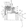
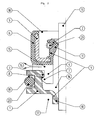
- FIGS. 1 and 2 each show a sealing arrangement which consists of a first sealing ring 1 and a second sealing ring 2.
- the seal assembly with the two sealing rings 1, 2 is intended for use in a tandem pump and seals heavy or incompatible media against each other.
- the two sealing rings 1, 2 are associated axially adjacent to one another and each have a dynamically stressed sealing lip 10, 11, wherein the sealing lips 10, 11 are associated with each other adjacent to an axial spacing.
- the sealing arrangements are each shown in the production-related, non-installed state.
- a machine element to be sealed 13 is shown in dashed lines, as well as the mounting-related shape of the sealing lip 10 of the first sealing ring. 1
- the sealing lips 10, 11 enclose the surface 12 of the machine element 13 to be sealed under elastic prestress and limit a cavity 14 in the axial direction.
- the sealing lips 10, 11 are bulged axially in the direction of the respective space 17, 18 to be sealed.
- the second sealing ring 2 has at least one recess 15, which is arranged at the lowest point of the sealing arrangement. From the spaces to be sealed 1.7, 18 leaking leakage passes through the recess 15 in the environment 16 and thereby indicates that at least one of the sealing rings 1, 2 must be replaced.
- the recess 15 may alternatively be arranged in the first sealing ring 1.
- the recess 15 may comprise two partial areas, one of which forms part of the first sealing ring 1 and the other forms part of the second sealing ring 2.
- the recess 15 preferably forms part of the connecting means 3, 4, in the embodiments shown here forms part of the connecting means 4 of the second sealing ring 2. Also by the additional function of the connecting device 4 as a recess 15 for removing leakage from the cavity 14 into the environment 16, the sealing arrangements shown here have a simple and low-part construction.
- the first sealing ring 1 is made of a PTFE compound and is self-supporting, ie formed without support body.
- the connecting device 3 of the first sealing ring 1 is integrally formed and of the same material with this.
- FIG. 1 shows a first exemplary embodiment of the sealing arrangement.
- the second sealing ring 2 is made entirely of elastomeric material.
- a second sealing ring 2 is shown in the embodiment of Figure 2, comprising a support body 5 made of sheet metal, which is enclosed by the jacket 6 made of elastomeric material.
- the sealing lip 11 of the second sealing ring 2 is pressed by the ring helical spring 21, which consists of spring steel, to the surface 12 of the machine element 13 to be sealed.
- the connecting device 4 provided with the recess 15 is provided with a circumferentially encircling, locking cam-shaped projection 7 which is snapped into the annular, undercut recess 8 of the first sealing ring 1.
- the first and second sealing ring 2 are non-destructively releasably connected to each other and thereby, if necessary, separately exchangeable.
Landscapes
- Engineering & Computer Science (AREA)
- General Engineering & Computer Science (AREA)
- Mechanical Engineering (AREA)
- Sealing With Elastic Sealing Lips (AREA)
- Sealing Devices (AREA)
- Gasket Seals (AREA)
- Connector Housings Or Holding Contact Members (AREA)
Abstract
Description
Die Erfindung betrifft eine Dichtungsanordnung, umfassend einen ersten und einen zweiten Dichtring, die einander axial benachbart zugeordnet und verliersicher miteinander verbunden sind, wobei zumindest der erste Dichtring selbsttragend, d.h. stützkörperlos ausgebildet ist und aus polymerem Werkstoff besteht, wobei beide Dichtringe auf den einander zugewandten Seiten jeweils eine Verbindungseinrichtung aufweisen und wobei die Verbindungseinrichtung des ersten Dichtrings einstückig und materialeinheitlich mit diesem ausgebildet ist, wobei der erste und der zweite Dichtring jeweils zumindest eine im Betrieb dynamisch beanspruchte Dichtlippe aufweisen, wobei die Dichtlippen mit axialem Abstand zueinander benachbart angeordnet sind und wobei die Dichtlippen mit radialer Vorspannung dichtend an die Oberfläche eines abzudichtenden Maschinenelements anlegbar sind und in axialer Richtung einen Hohlraum begrenzen.The invention relates to a sealing arrangement, comprising a first and a second sealing ring, which are assigned to each other axially adjacent and captively connected to each other, wherein at least the first sealing ring self-supporting, i. is formed Stützkörperlos and consists of polymeric material, wherein both sealing rings on the facing sides each having a connecting device and wherein the connecting means of the first sealing ring is formed integrally and of the same material therewith, wherein the first and the second sealing ring each at least one dynamically stressed during operation Have sealing lip, wherein the sealing lips are arranged adjacent to each other at an axial distance and wherein the sealing lips are sealingly applied with radial bias to the surface of a machine element to be sealed and define a cavity in the axial direction.
Eine solche Dichtungsanordnung ist aus der US 4,053,166 bekannt. Die vorbekannte Dichtungsanordnung ist zur Abdichtung translatorisch hin- und herbewegbarer Maschinenelemente vorgesehen, wobei die Dichtringe in einer funktionstechnischen Reihenschaltung angeordnet sind. Die beiden Dichtringe umschließen mit jeweils einer dynamisch beanspruchten Dichtlippe die abzudichtende Oberfläche einer hin- und hergehenden Stange, wobei der dem abzudichtenden Raum axial zugewandte Dichtring vergleichsweise weicher ist und aus einem elastomeren Werkstoff besteht. Auf der dem abzudichtenden Raum axial abgewandten Seite des ersten Dichtrings ist der zweite, vergleichsweise härtere Dichtring angeordnet, der beispielsweise aus PTFE besteht.
Die Verbindungseinrichtung der beiden Dichtringe ist jeweils einstückig und materialeinheitlich mit dem jeweiligen Dichtring ausgebildet, wobei einer der Dichtringe einen Vorsprung und der andere Dichtring eine kongruent gestaltete Ausnehmung aufweist und wobei der Vorsprung und die Ausnehmung formschlüssig miteinander verbunden sind. Die Dichtlippe des vergleichsweise härteren Dichtrings ist als Stützkörper für die Dichtlippe des vergleichsweise weicheren Dichtrings ausgeführt, so dass die Dichtlippe des weicheren Dichtrings auch bei vergleichsweise großer Druckbeaufschlagung funktioniert. Auch bei großer Druckbeaufschlagung der Dichtungsanordnung wird die Reibung nicht unerwünscht hoch, da der vergleichsweise härtere Dichtring, der als Stützring für den weicheren Dichtring ausgebildet ist, aus PTFE besteht.Such a sealing arrangement is known from US 4,053,166. The previously known sealing arrangement is translationally to seal off and herbewegbarer machine elements provided, wherein the sealing rings are arranged in a functional series connection. The two sealing rings each enclose with a dynamically stressed sealing lip the surface of a reciprocating rod to be sealed, wherein the sealing ring facing the space to be sealed is comparatively softer and consists of an elastomeric material. On the side facing away from the space to be sealed axially of the first sealing ring of the second, relatively harder sealing ring is arranged, which consists for example of PTFE.
The connecting device of the two sealing rings is in each case formed in one piece and of the same material with the respective sealing ring, wherein one of the sealing rings has a projection and the other sealing ring has a congruently designed recess and wherein the projection and the recess are positively connected with each other. The sealing lip of the relatively harder sealing ring is designed as a support body for the sealing lip of the comparatively softer sealing ring, so that the sealing lip of the softer sealing ring works even with relatively large pressurization. Even with large pressurization of the seal arrangement, the friction is not undesirably high, since the comparatively harder sealing ring, which is designed as a support ring for the softer sealing ring, consists of PTFE.
Aus der US 5,727,794 ist eine weitere Dichtungsanordnung bekannt, umfassend zwei Dichtringe, die als Gleichteile ausgebildet und miteinander verbunden sind. Die montierten Dichtringe sind durch Abstandshalter axial einander benachbart zugeordnet und weisen axial entgegengesetzt vorstehende Dichtlippen auf. Die beiden Dichtringe der Dichtungsanordnung sind vorgesehen, axial zueinander benachbart angeordnete, abzudichtende Räume voneinander zu trennen, wobei die Dichtlippen der Dichtringe, im Schnitt betrachtet, einen kreisringförmigen Hohlraum begrenzen, der entlang seines gesamten Außenumfangs mit der Umgebung verbunden ist. Leckage, die aus den abzudichtenden Räumen in den Hohlraum axial zwischen den Dichtlippen entweicht, kann durch einen Kanal zwischen den Dichtringen an die Umgebung abgeführt werden.
Die axiale Weite der Verbindung, die den Hohlraum mit der Umgebung verbindet, ist weitgehend abhängig von der Montage der Dichtungsanordnung; abhängig von der Sorgfältigkeit, mit der die Montage vorgenommen wird, differieren die geometrischen Abmessungen der Verbindung. Die Verbindung wird axial durch die beiden Rückenan-Rücken montierten Dichtringe begrenzt.From US 5,727,794 another seal assembly is known, comprising two sealing rings, which are designed as common parts and connected to each other. The mounted sealing rings are assigned by spacers axially adjacent to each other and axially oppositely projecting sealing lips. The two sealing rings of the seal assembly are provided axially adjacent to each other to be sealed, spaces to be separated from each other, wherein the sealing lips of the sealing rings, viewed in section, define an annular cavity, which is connected along its entire outer circumference with the environment. Leakage, which escapes from the spaces to be sealed into the cavity axially between the sealing lips can be removed through a channel between the sealing rings to the environment.
The axial width of the connection, which connects the cavity with the environment, is largely dependent on the assembly of the seal assembly; Depending on the accuracy with which the assembly is made, the geometric dimensions of the connection differ. The connection is limited axially by the two back-mounted seals.
Eine weitere Dichtungsanordnungen ist aus der DE 36 19 309 C1 bekannt. Die vorbekannte Dichtungsanordnung gelangt als Kühlwasserpumpendichtung zur Anwendung und umfasst eine Hauptdichtung, der kühlwasserseitig eine Schutzdichtung vorgeschaltet ist. Die Schutzdichtung besteht aus einem Filtervlies und ist außenseitig in einem Stützkörper aus Kunststoff gehalten. Dieser Stützkörper der Schutzdichtung ist durch eine Steckverbindung an einem Stützkörper der Hauptdichtung festgelegt.Another seal assemblies is known from DE 36 19 309 C1. The previously known sealing arrangement is used as a cooling water pump seal for use and comprises a main seal, the cooling water side, a protective seal is connected upstream. The protective seal consists of a filter fleece and is held on the outside in a plastic support body. This support body of the protective seal is fixed by a plug connection to a support body of the main seal.
Der Erfindung liegt die Aufgabe zugrunde, eine Dichtungsanordnung der eingangs genannten Art derart weiterzuentwickeln, dass diese einen einfachen und teilearmen Aufbau hat und deshalb in fertigungstechnischer und wirtschaftlicher Hinsicht einfach und kostengünstig herstellbar ist und dass Leckage aus diesem Bereich sicher an die Umgebung abgeführt und ein unerwünschter Druckaufbau axial zwischen den Dichtlippen vermieden wird.The invention has the object of providing a seal assembly of the type mentioned in such a way that it has a simple and low-part construction and therefore in manufacturing technology and economic terms is simple and inexpensive to produce and that leakage from this area safely dissipated to the environment and an undesirable Pressure build-up is avoided axially between the sealing lips.
Diese Aufgabe wird erfindungsgemäß mit den Merkmalen von Anspruch 1 gelöst. Auf vorteilhafte Ausgestaltungen nehmen die Unteransprüche Bezug.This object is achieved with the features of
Zur Lösung der Aufgabe ist eine Dichtungsanordnung vorgesehen, umfassend einen ersten und einen zweiten Dichtring, die einander axial benachbart zugeordnet und verliersicher miteinander verbunden sind, wobei zumindest der erste Dichtring selbsttragend, d.h. stützkörperlos ausgebildet ist und aus polymerem Werkstoff besteht, wobei beide Dichtringe auf den einander zugewandten Seiten jeweils eine Verbindungseinrichtung aufweisen und wobei die Verbindungseinrichtung des ersten Dichtrings einstückig und materialeinheitlich mit diesem ausgebildet ist, wobei der erste und der zweite Dichtring jeweils zumindest eine im Betrieb dynamisch beanspruchte Dichtlippe aufweisen, wobei die Dichtlippen mit axialem Abstand zueinander benachbart angeordnet sind und wobei die Dichtlippen mit radialer Vorspannung dichtend an die Oberfläche eines abzudichtenden Maschinenelements anlegbar sind und in axialer Richtung einen Hohlraum begrenzen und wobei zumindest einer der Dichtringe im Bereich axial zwischen den Dichtlippen zumindest eine Ausnehmung, die einen Bestandteil der Verbindungseinrichtung bildet, aufweist, die den Hohlraum zur Abführung von Leckage mit der Umgebung verbindet.To achieve the object, a sealing arrangement is provided, comprising a first and a second sealing ring, which axially adjacent to each other assigned and captive are connected to each other, wherein at least the first sealing ring is self-supporting, ie consists of supportive material and consists of polymeric material, both sealing rings on the facing sides each having a connecting device and wherein the connecting means of the first sealing ring is formed integrally and of the same material with this wherein the first and the second sealing ring each have at least one dynamically stressed during operation sealing lip, wherein the sealing lips are arranged adjacent to each other at an axial distance and wherein the sealing lips with radial bias sealingly against the surface of a sealed machine element can be applied and in the axial direction a cavity limit and wherein at least one of the sealing rings in the region axially between the sealing lips at least one recess which forms a part of the connecting device, which has the cavity for discharging v on leakage connects with the environment.
Der stützkörperlose erste Dichtring ist einstückig und materialeinheitlich ausgebildet und besteht beispielsweise aus einem PTFE-Compound. Der Werkstoff ist derart ausgewählt, dass er einerseits eine gute Abdichtung des abzudichtenden Raums gegenüber der Umgebung ermöglicht und andererseits eine haltbare Verbindungseinrichtung, die mit der Verbindungseinrichtung des zweiten Dichtrings zusammenwirkt. Der einstückige, materialeinheitliche erste Dichtring ist außerdem bezüglich eines einfachen, sortenreinen Recyclings von hervorzuhebendem Vorteil. Einer Trennung unterschiedlicher Materialien vor dem Recycling, die beispielsweise bei Dichtringen mit einem Stützkörper aus einem metallischen Werkstoff durchgeführt werden muß, bedarf es dabei nicht.The non-supporting first sealing ring is formed in one piece and of uniform material and consists for example of a PTFE compound. The material is selected such that on the one hand it enables a good sealing of the space to be sealed from the environment and on the other hand a durable connecting device which cooperates with the connecting device of the second sealing ring. The one-piece, uniform material first sealing ring is also in terms of a simple, unmixed recycling of hervorzuhebendem advantage. A separation of different materials prior to recycling, which must be performed, for example, in sealing rings with a support body made of a metallic material, it is not required.
Der erste und der zweite Dichtring weisen jeweils zumindest eine dynamisch beanspruchte Dichtlippe auf, wobei die Dichtlippen mit axialem Abstand zueinander benachbart angeordnet sind und wobei die Dichtlippen mit radialer Vorspannung dichtend an die Oberfläche eines abzudichtenden Maschinenelements anlegbar sind und in axialer Richtung einen Hohlraum begrenzen. Eine solche Anordnung hat sich insbesondere dann bewährt, wenn die Dichtungsanordnung zur Trennung von schwer- bzw. unverträglichen Medien zur Anwendung gelangt, wobei die Medien beispielsweise eine unterschiedliche Schmiercharakteristik aufweisen. Die Dichtungsanordnung kann beispielsweise in Tandempumpen zur Anwendung gelangen.The first and the second sealing ring each have at least one dynamically stressed sealing lip, wherein the sealing lips are arranged adjacent to each other at an axial distance and wherein the sealing lips with radial bias sealing to the surface of a machine element to be sealed can be applied and limit a cavity in the axial direction. Such an arrangement has proven particularly useful when the sealing arrangement for the separation of difficult or incompatible media is used, wherein the media, for example, have a different lubricating characteristic. The seal arrangement can be used, for example, in tandem pumps.
Zumindest einer der Dichtringe weist im Bereich axial zwischen den Dichtlippen zumindest eine Ausnehmung auf, die den Hohlraum zur Abführung von Leckage mit der Umgebung verbindet. Dadurch ist sichergestellt, dass betriebsbedingt auftretende Leckage innerhalb des Hohlraums nicht zu einem unerwünschten Druckaufbau zwischen den Dichtlippen führt und dadurch zu unerwünscht negativen Gebrauchseigenschaften über einen längeren Zeitraum. Bei der erfindungsgemäßen Dichtungsanordnung wird die Leckage aus dem Hohlraum in die Umgebung abgeführt und zeigt dadurch an, dass zumindest einer der Dichtringe verschlissen/beschädigt ist und deshalb ausgetauscht werden muss. Die in die Umgebung abgeführte Leckage ist demnach ein Indikator für die Funktionsfähigkeit/den Zustand der Dichtungsanordnung.At least one of the sealing rings has at least one recess in the region between the sealing lips, which connects the cavity for discharging leakage with the environment. This ensures that operationally occurring leakage within the cavity does not lead to an undesirable pressure build-up between the sealing lips and thereby undesirable negative performance characteristics over a longer period. In the sealing arrangement according to the invention, the leakage is discharged from the cavity into the environment and indicates that at least one of the sealing rings is worn / damaged and therefore has to be replaced. The discharged into the environment leakage is therefore an indicator of the functionality / the state of the seal assembly.
Nach einer ersten Ausgestaltung kann es vorgesehen sein, dass der zweite Dichtring vollständig aus elastomerem Werkstoff besteht und dass die Verbindungseinrichtung des zweiten Dichtrings einstückig und materialeinheitlich mit diesem ausgebildet ist. In dieser Ausgestaltung ist auch der zweite Dichtring selbsttragend, d.h. stützkörperlos ausgebildet. Eine solche Dichtungsanordnung mit zwei Dichtringen besteht dann insgesamt aus nur zwei voneinander abweichenden Werkstoffen, nämlich einem polymeren Werkstoff, aus dem der erste Dichtring besteht und einem elastomeren Werkstoff, aus dem der zweite Dichtring besteht.According to a first embodiment, it can be provided that the second sealing ring is made entirely of elastomeric material and that the connecting device of the second sealing ring is formed integrally and with the same material. In this embodiment, the second sealing ring is self-supporting, ie trained supportive body. Such a sealing arrangement with two sealing rings then consists entirely of only two divergent materials, namely a polymeric material of which the first sealing ring is made and an elastomeric material of which the second sealing ring is made.
Für manche Anwendungsfälle ist es vorteilhaft, wenn der zweite Dichtring einen Stützkörper aus zähhartem Werkstoff umfasst, der zumindest teilweise von einem Mantel aus elastomerem Werkstoff umschlossen ist, wobei die Verbindungseinrichtung des zweiten Dichtrings einstückig und materialeinheitlich mit dem Mantel ausgebildet ist. Der Stützring kann dabei beispielsweise aus einem polymeren Werkstoff bestehen oder aus einem tiefgezogenen Blech. Ein zweiter Dichtring mit Stützkörper ist insbesondere dann sinnvoll, wenn der zweite Dichtring in eine Bohrung eines Gehäuses eingepresst ist und die Bohrung des Gehäuses gegenüber der Umgebung statisch abdichten soll. Am Stützkörper kann eine dynamisch beanspruchte Dichtlippe angeformt sein, die aus elastomerem Werkstoff besteht und eiristückig und materialeinheitlich mit dem Mantel ausgebildet ist. Die Dichtlippe kann beispielsweise durch eine Ringwendelfeder an die Oberfläche des abzudichtenden Maschinenelements angepresst sein.For some applications, it is advantageous if the second sealing ring comprises a support body of tough material, which is at least partially enclosed by a jacket made of elastomeric material, wherein the connecting means of the second sealing ring is formed integrally and of the same material with the jacket. The support ring may for example consist of a polymeric material or of a thermoformed sheet. A second sealing ring with supporting body is particularly useful when the second sealing ring is pressed into a bore of a housing and to seal the bore of the housing relative to the environment statically. On the support body, a dynamically stressed sealing lip may be formed, which consists of elastomeric material and eiristückig and is formed of the same material with the jacket. The sealing lip can be pressed against the surface of the machine element to be sealed, for example, by an annular helical spring.
Die Verbindungseinrichtung eines der Dichtringe kann durch zumindest einen rastnockenförmigen Vorsprung gebildet sein und die Verbindungseinrichtung des anderen Dichtrings durch eine hinterschnittene Ausnehmung, wobei der Vorsprung und die Ausnehmung ineinander einschnappbar sind. Solche rastnockenförmigen Verbindungseinrichtungen sind einfach herstell- und montierbar. Montagefehler bei der Verbindung der beiden Dichtringe sind dadurch auf ein Minimum begrenzt.The connecting means of one of the sealing rings can be formed by at least one locking cam-shaped projection and the connecting means of the other sealing ring by an undercut recess, wherein the projection and the recess are snapped into each other. Such locking cam-shaped connecting devices are easy to manufacture and assemble. Assembly errors in the connection of the two sealing rings are thereby limited to a minimum.
Durch die rastnockenförmige Verbindung der beiden Dichtringe miteinander, sind diese auf einfache Weise zerstörungsfrei lösbar miteinander verbunden. Dies ist insofern von Vorteil, als die Dichtringe, abhängig vom jeweiligen Verschleiß, jeweils separat austauschbar sind. So besteht beispielsweise die Möglichkeit, den aus einem elastomeren Werkstoff bestehenden zweiten Dichtring wegen seines vergleichsweise höheren Verschleißes bei unerwünscht hoher Leckage auszutauschen und den vergleichsweise verschleißfesteren ersten Dichtring zusammen mit dem neuen, ausgetauschten zweiten Dichtring weiter zu verwenden.Due to the locking cam-shaped connection of the two sealing rings with each other, they are non-destructively releasably connected to each other in a simple manner. This is advantageous in that the sealing rings, depending on the respective wear, are each separately exchangeable. Thus, for example, it is possible to replace the existing of an elastomeric material second sealing ring because of its relatively higher wear at undesirably high leakage and the relatively wear-resistant continue to use the first sealing ring together with the new, replaced second sealing ring.
Generell können der erste Dichtring und der zweite Dichtring durch die Verbindungseinrichtungen kraft- und/oder formschlüssig miteinander verbunden sein.In general, the first sealing ring and the second sealing ring can be positively and / or positively connected to each other by the connecting means.
Der erste und der zweite Dichtring bilden bevorzugt eine vormontierbare Einheit, so dass Montagefehler bei der Montage der Dichtungsanordnung in ihren Einbauraum auf ein Minimum begrenzt sind.The first and the second sealing ring preferably form a preassemblable unit, so that assembly errors in the assembly of the seal assembly are limited in their installation space to a minimum.
Beispielsweise für einen solchen Anwendungsfall können die Dichtlippen der Dichtringe jeweils in axialer Richtung entgegen dem benachbarten Dichtring, axial in Richtung des jeweils abzudichtenden Raums vorgewölbt sein.For example, for such an application, the sealing lips of the sealing rings in each case in the axial direction against the adjacent sealing ring, be bulged axially in the direction of each space to be sealed.
Der erste Dichtring kann auf der seiner Dichtlippe radial abgewandten Seite eine radial offene Nut zur Aufnahme einer separat erzeugten, statisch beanspruchten Dichtung aufweisen. Wird beispielsweise durch die Dichtungsanordnung eine Welle abgedichtet, umschließen die dynamisch beanspruchten Dichtlippen die Oberfläche der abzudichtenden Welle unter elastischer Vorspannung dichtend. Die Nut ist in einem solchen Fall radial nach außen offen, wobei in der Nut beispielsweise ein O-Ring angeordnet ist, der ein die Dichtungsanordnung außenumfangsseitig umschließendes Gehäuse statisch gegenüber der Umgebung abdichtet.The first sealing ring may have a radially open groove for receiving a separately generated, statically stressed seal on the side facing away from its sealing lip radially. If, for example, a shaft is sealed by the sealing arrangement, the dynamically stressed sealing lips seal the surface of the shaft to be sealed under elastic prestressing. The groove is open radially outward in such a case, wherein in the groove, for example, an O-ring is arranged, which seals the outer peripheral side enclosing a housing seal statically relative to the environment.
Der erste Dichtring besteht im Wesentlichen aus PTFE. PTFE ist gegen die meisten abzudichtenden Medien resistent. Auch während einer außerordentlich langen Gebrauchsdauer unterliegt ein Dichtring aus einem solchen Werkstoff nur einem vernachlässigbar geringen, abrasiven Verschleiß, so dass die Dichtungsanordnung gleichbleibend gute Gebrauchseigenschaften während einer langen Gebrauchsdauer aufweist.The first sealing ring consists essentially of PTFE. PTFE is resistant to most media to be sealed. Even during an extremely long service life is subject to a sealing ring made of such a material only a negligible, abrasive wear, so that the seal assembly has consistently good performance for a long service life.
Zwei Ausführungsbeispiele der erfindungsgemäßen Dichtungsanordnung werden nachfolgend anhand der Figuren 1 und 2 näher erläutert.Two embodiments of the sealing arrangement according to the invention are explained in more detail below with reference to Figures 1 and 2.
Diese zeigen jeweils in schematischer Darstellung:
Figur 1- ein erstes Ausführungsbeispiel,
Figur 2- ein zweites Ausführungsbeispiel der erfindungsgemäßen Dichtungsanordnung.
- FIG. 1
- a first embodiment,
- FIG. 2
- A second embodiment of the seal assembly according to the invention.
In den Figuren 1 und 2 ist jeweils eine Dichtungsanordnung gezeigt, die aus einem ersten 1 und einem zweiten Dichtring 2 besteht. Die Dichtungsanordnung mit den beiden Dichtringen 1, 2 ist zur Verwendung in einer Tandempumpe vorgesehen und dichtet schwer- bzw. unverträgliche Medien gegeneinander ab. Dazu sind die beiden Dichtringe 1, 2 einander axial benachbart zugeordnet und weisen jeweils eine dynamisch beanspruchte Dichtlippe 10, 11 auf, wobei die Dichtlippen 10, 11 einander mit axialem Abstand benachbart zugeordnet sind.FIGS. 1 and 2 each show a sealing arrangement which consists of a
Die Dichtungsanordnungen sind jeweils im herstellungsbedingten, nichteingebauten Zustand gezeigt.The sealing arrangements are each shown in the production-related, non-installed state.
Ein abzudichtendes Maschinenelement 13 ist gestrichelt dargestellt, ebenso wie die montagebedingte Form der Dichtlippe 10 des ersten Dichtrings 1.A machine element to be sealed 13 is shown in dashed lines, as well as the mounting-related shape of the sealing
Während der bestimmungsgemäßen Verwendung der Dichtungsanordnung umschließen die Dichtlippen 10, 11 die Oberfläche 12 des abzudichtenden Maschinenelements 13 unter elastischer Vorspannung anliegend und begrenzen in axialer Richtung einen Hohlraum 14. Die Dichtlippen 10, 11 sind axial in Richtung des jeweils abzudichtenden Raums 17, 18 vorgewölbt.During the intended use of the sealing arrangement, the sealing
Zur Abführung von Leckage aus dem Hohlraum 14 in die Umgebung 16 weist in diesem Ausführungsbeispiel der zweite Dichtring 2 zumindest eine Ausnehmung 15 auf, die an der tiefsten Stelle der Dichtungsanordnung angeordnet ist. Aus den abzudichtenden Räumen 1.7, 18 austretende Leckage gelangt durch die Ausnehmung 15 in die Umgebung 16 und zeigt dadurch an, dass zumindest einer der Dichtringe 1, 2 ausgetauscht werden muss. Die Ausnehmung 15 kann alternativ auch im ersten Dichtring 1 angeordnet sein. Als weitere Ausgestaltung kann die Ausnehmung 15 zwei Teilbereiche umfassen, von denen einer einen Bestandteil des ersten Dichtrings 1 und der andere einen Bestandteil des zweiten Dichtrings 2 bildet.For discharging leakage from the
Von hervorzuhebendem Vorteil ist, dass die Ausnehmung 15 bevorzugt einen Bestandteil der Verbindungseinrichtungen 3, 4, in den hier gezeigten Ausführungsbeispielen einen Bestandteil der Verbindungseinrichtung 4 des zweiten Dichtrings 2 bildet. Auch durch die zusätzliche Funktion der Verbindungseinrichtung 4 als Ausnehmung 15 zur Abführung von Leckage aus dem Hohlraum 14 in die Umgebung 16, weisen die hier gezeigten Dichtungsanordnungen einen einfachen und teilearmen Aufbau auf.Of hervorzuhebendem advantage is that the
In den hier gezeigten Ausführungsbeispielen besteht der erste Dichtring 1 aus einem PTFE-Compound und ist selbsttragend, d.h. stützkörperlos ausgebildet. Die Verbindungseinrichtung 3 des ersten Dichtrings 1 ist einstückig und materialeinheitlich mit diesem ausgebildet.In the embodiments shown here, the
In Figur 1 ist ein erstes Ausführungsbeispiel der Dichtungsanordnung gezeigt. Der zweite Dichtring 2 besteht vollständig aus elastomerem Werkstoff.FIG. 1 shows a first exemplary embodiment of the sealing arrangement. The
Demgegenüber ist im Ausführungsbeispiel aus Figur 2 ein zweiter Dichtring 2 gezeigt, der einen Stützkörper 5 aus Blech umfasst, der von dem Mantel 6 aus elastomerem Werkstoff umschlossen ist. Die Dichtlippe 11 des zweiten Dichtrings 2 wird durch die Ringwendelfeder 21, die aus Federstahl besteht, an die Oberfläche 12 des abzudichtenden Maschinenelements 13 angepresst.In contrast, a
Sowohl im Ausführungsbeispiel gemäß Figur 1 als auch im Ausführungsbeispiel gemäß Figur 2 ist die mit der Ausnehmung 15 versehene Verbindungseinrichtung 4 mit einem umfangsseitig umlaufenden, rastnockenförmigen Vorsprung 7 versehen, der in die ringförmige, hinterschnittene Ausnehmung 8 des ersten Dichtrings 1 eingeschnappt ist. Der erste und der zweite Dichtring 2 sind zerstörungsfrei lösbar miteinander verbunden und dadurch bedarfsweise separat austauschbar.In the embodiment according to FIG. 1 as well as in the exemplary embodiment according to FIG. 2, the connecting
Claims (10)
- Sealing arrangement, comprising a first sealing ring (1) and a second sealing ring (2), which are axially adjacent to each other and captively connected to each other, at least the first sealing ring (1) being formed in a self-supporting manner, i.e. without a supporting body, and consisting of polymeric material, both sealing rings (1, 2) respectively having a connecting device (3, 4) on the mutually facing sides, and the connecting device (3) of the first sealing ring (1) being formed in one piece with it and of the same material, the first sealing ring (1) and the second sealing ring (2) respectively having at least one sealing lip (10, 11) that is under dynamic loading during operation, the sealing lips (10, 11) being arranged adjacent to each other with an axial spacing and the sealing lips (10, 11) being able to be placed with radial prestress in a sealing manner against the surface (12) of a machine element (13) to be sealed off and bounding a cavity (14) in the axial direction, characterized in that at least one of the sealing rings (2) has in the region axially between the sealing lips (10, 11) at least one recess (15), which forms a component part of the connecting device (4), which connects the cavity (14) to the surroundings (16) for the discharge of leakage.
- Sealing arrangement according to Claim 1, characterized in that the second sealing ring (2) consists completely of elastomeric material and in that the connecting device (4) of the second sealing ring (2) is formed in one piece with it and of the same material.
- Sealing arrangement according to Claim 1, characterized in that the second sealing ring (2) comprises a supporting body (5) of hard and tough material, which is enclosed at least partially by a shell (6) of elastomeric material, and in that the connecting device (4) of the second sealing ring (2) is formed in one piece with the shell (6) and of the same material.
- Sealing arrangement according to one of Claims 1 to 3, characterized in that the connecting device (4) of one of the sealing rings (2) is formed by at least one projection (7) in the form of a latching lug and the connecting device (3) of the other sealing ring (1) is formed by an undercut recess (8), and in that the projection (7) and the recess (8) can be snap-fitted one into the other.
- Sealing arrangement according to one of Claims 1 to 4, characterized in that the first sealing ring (1) and the second sealing ring (2) are connected to each other in a nondestructively releasable manner.
- Sealing arrangement according to one of Claims 1 to 5, characterized in that the first sealing ring (1) and the second sealing ring (2) are connected to each other by the connecting devices (3, 4) in a non-positively and/or positively engaging manner.
- Sealing arrangement according to one of Claims 1 to 6, characterized in that the first sealing ring (1) and the second sealing ring (2) form a unit (9) that can be preassembled.
- Sealing arrangement according to one of Claims 1 to 7, characterized in that the sealing lips (10, 11) of the sealing rings (1, 2) are respectively made to protrude counter to the adjacent sealing ring (2, 1) in the axial direction, axially in the direction of the space (17, 18) respectively to be sealed off.
- Sealing arrangement according to one of Claims 1 to 8, characterized in that the first sealing ring (1) has on the side radially facing away from its sealing lip (10) a radially open groove (19) for receiving a separately produced, statically loaded seal (20).
- Sealing arrangement according to one of Claims 1 to 9, characterized in that the first sealing ring (1) consists substantially of PTFE.
Applications Claiming Priority (2)
| Application Number | Priority Date | Filing Date | Title |
|---|---|---|---|
| DE10236831 | 2002-08-10 | ||
| DE10236831A DE10236831A1 (en) | 2002-08-10 | 2002-08-10 | sealing arrangement |
Publications (3)
| Publication Number | Publication Date |
|---|---|
| EP1388694A2 EP1388694A2 (en) | 2004-02-11 |
| EP1388694A3 EP1388694A3 (en) | 2004-05-06 |
| EP1388694B1 true EP1388694B1 (en) | 2006-01-11 |
Family
ID=30128828
Family Applications (1)
| Application Number | Title | Priority Date | Filing Date |
|---|---|---|---|
| EP03015408A Expired - Lifetime EP1388694B1 (en) | 2002-08-10 | 2003-07-09 | Sealing arrangement |
Country Status (3)
| Country | Link |
|---|---|
| EP (1) | EP1388694B1 (en) |
| AT (1) | ATE315746T1 (en) |
| DE (1) | DE10236831A1 (en) |
Families Citing this family (2)
| Publication number | Priority date | Publication date | Assignee | Title |
|---|---|---|---|---|
| EP2362119B1 (en) * | 2010-02-19 | 2015-09-02 | Carl Freudenberg KG | Radial shaft seal for separating two media |
| DE102013218904B4 (en) * | 2013-09-20 | 2015-09-17 | Aktiebolaget Skf | sealing element |
Family Cites Families (4)
| Publication number | Priority date | Publication date | Assignee | Title |
|---|---|---|---|---|
| US4053166A (en) * | 1975-12-08 | 1977-10-11 | Halogen Insulator & Seal Corporation | Two-piece seal |
| DE3619309C1 (en) | 1986-06-07 | 1987-09-17 | Freudenberg Carl Fa | Cooling water pump seal |
| IT1276368B1 (en) * | 1995-06-09 | 1997-10-31 | Stefa S R L | LIP SEALING COMPLEX. |
| DE50012612D1 (en) * | 1999-08-06 | 2006-05-24 | Luk Fahrzeug Hydraulik | WAVE SEALING FOR A CO2 COMPRESSOR |
-
2002
- 2002-08-10 DE DE10236831A patent/DE10236831A1/en not_active Withdrawn
-
2003
- 2003-07-09 EP EP03015408A patent/EP1388694B1/en not_active Expired - Lifetime
- 2003-07-09 AT AT03015408T patent/ATE315746T1/en not_active IP Right Cessation
Also Published As
| Publication number | Publication date |
|---|---|
| DE10236831A1 (en) | 2004-02-26 |
| EP1388694A2 (en) | 2004-02-11 |
| ATE315746T1 (en) | 2006-02-15 |
| EP1388694A3 (en) | 2004-05-06 |
Similar Documents
| Publication | Publication Date | Title |
|---|---|---|
| EP1156241B1 (en) | Annular sleeve seal, especially for mounting in housings with reduced dimensions | |
| DE69937495T2 (en) | WAVE SEAL AND METHOD OF MANUFACTURING | |
| EP0431263A1 (en) | Seal unit | |
| EP1299662A1 (en) | Shaft sealing ring | |
| DE3601149A1 (en) | GASKET AND SUPPORT RING ARRANGEMENT FOR THIS | |
| EP2362119B1 (en) | Radial shaft seal for separating two media | |
| DE102013208203A1 (en) | roller bearing | |
| DE19728605C2 (en) | Rod or piston seal | |
| EP1731804A1 (en) | Sealing and assembly provided with sealing lips in series | |
| EP0798498A1 (en) | Radial lip seal with excluding effect independent of the rotation direction | |
| EP3492785A1 (en) | Sealing ring and seal arrangement comprising such a sealing ring | |
| DE102017006288A1 (en) | Radial shaft seal and its use | |
| DE2546805C3 (en) | Sealing ring for rotatable bodies, such as shafts or the like. | |
| DE19841123B4 (en) | Radial shaft seal | |
| DE10309907B4 (en) | seal | |
| DE19726433C2 (en) | Sealing arrangement | |
| EP1388694A2 (en) | Sealing arrangement | |
| EP2647889A2 (en) | Seal arrangement | |
| DE102018105393B3 (en) | Sealing ring and seal assembly comprising the sealing ring | |
| DE29716258U1 (en) | Mechanical seal | |
| EP2861897B2 (en) | Slide ring seal | |
| DE3336863A1 (en) | Radial shaft sealing ring | |
| DE10140731B4 (en) | seal | |
| EP1248025B1 (en) | Sealing ring | |
| DE102018000128A1 (en) | bellows |
Legal Events
| Date | Code | Title | Description |
|---|---|---|---|
| PUAI | Public reference made under article 153(3) epc to a published international application that has entered the european phase |
Free format text: ORIGINAL CODE: 0009012 |
|
| 17P | Request for examination filed |
Effective date: 20030718 |
|
| AK | Designated contracting states |
Kind code of ref document: A2 Designated state(s): AT BE BG CH CY CZ DE DK EE ES FI FR GB GR HU IE IT LI LU MC NL PT RO SE SI SK TR |
|
| AX | Request for extension of the european patent |
Extension state: AL LT LV MK |
|
| PUAL | Search report despatched |
Free format text: ORIGINAL CODE: 0009013 |
|
| AK | Designated contracting states |
Kind code of ref document: A3 Designated state(s): AT BE BG CH CY CZ DE DK EE ES FI FR GB GR HU IE IT LI LU MC NL PT RO SE SI SK TR |
|
| AX | Request for extension of the european patent |
Extension state: AL LT LV MK |
|
| RIC1 | Information provided on ipc code assigned before grant |
Ipc: 7F 16J 15/00 B Ipc: 7F 16J 15/32 A |
|
| 17Q | First examination report despatched |
Effective date: 20040705 |
|
| REG | Reference to a national code |
Ref country code: DE Ref legal event code: 8566 |
|
| AKX | Designation fees paid |
Designated state(s): AT ES FR GB IT SE |
|
| GRAP | Despatch of communication of intention to grant a patent |
Free format text: ORIGINAL CODE: EPIDOSNIGR1 |
|
| GRAS | Grant fee paid |
Free format text: ORIGINAL CODE: EPIDOSNIGR3 |
|
| GRAA | (expected) grant |
Free format text: ORIGINAL CODE: 0009210 |
|
| AK | Designated contracting states |
Kind code of ref document: B1 Designated state(s): AT ES FR GB IT SE |
|
| PG25 | Lapsed in a contracting state [announced via postgrant information from national office to epo] |
Ref country code: GB Free format text: LAPSE BECAUSE OF FAILURE TO SUBMIT A TRANSLATION OF THE DESCRIPTION OR TO PAY THE FEE WITHIN THE PRESCRIBED TIME-LIMIT Effective date: 20060111 |
|
| PG25 | Lapsed in a contracting state [announced via postgrant information from national office to epo] |
Ref country code: SE Free format text: LAPSE BECAUSE OF FAILURE TO SUBMIT A TRANSLATION OF THE DESCRIPTION OR TO PAY THE FEE WITHIN THE PRESCRIBED TIME-LIMIT Effective date: 20060411 |
|
| PG25 | Lapsed in a contracting state [announced via postgrant information from national office to epo] |
Ref country code: ES Free format text: LAPSE BECAUSE OF FAILURE TO SUBMIT A TRANSLATION OF THE DESCRIPTION OR TO PAY THE FEE WITHIN THE PRESCRIBED TIME-LIMIT Effective date: 20060422 |
|
| ET | Fr: translation filed | ||
| GBV | Gb: ep patent (uk) treated as always having been void in accordance with gb section 77(7)/1977 [no translation filed] |
Effective date: 20060111 |
|
| PLBE | No opposition filed within time limit |
Free format text: ORIGINAL CODE: 0009261 |
|
| STAA | Information on the status of an ep patent application or granted ep patent |
Free format text: STATUS: NO OPPOSITION FILED WITHIN TIME LIMIT |
|
| 26N | No opposition filed |
Effective date: 20061012 |
|
| PG25 | Lapsed in a contracting state [announced via postgrant information from national office to epo] |
Ref country code: AT Free format text: LAPSE BECAUSE OF NON-PAYMENT OF DUE FEES Effective date: 20060709 |
|
| PGFP | Annual fee paid to national office [announced via postgrant information from national office to epo] |
Ref country code: FR Payment date: 20090722 Year of fee payment: 7 |
|
| PGFP | Annual fee paid to national office [announced via postgrant information from national office to epo] |
Ref country code: IT Payment date: 20090723 Year of fee payment: 7 |
|
| REG | Reference to a national code |
Ref country code: FR Ref legal event code: ST Effective date: 20110331 |
|
| PG25 | Lapsed in a contracting state [announced via postgrant information from national office to epo] |
Ref country code: FR Free format text: LAPSE BECAUSE OF NON-PAYMENT OF DUE FEES Effective date: 20100802 Ref country code: IT Free format text: LAPSE BECAUSE OF NON-PAYMENT OF DUE FEES Effective date: 20100709 |