EP2860622A1 - Electronic device and controlling method and program therefor - Google Patents
Electronic device and controlling method and program therefor Download PDFInfo
- Publication number
- EP2860622A1 EP2860622A1 EP20130800160 EP13800160A EP2860622A1 EP 2860622 A1 EP2860622 A1 EP 2860622A1 EP 20130800160 EP20130800160 EP 20130800160 EP 13800160 A EP13800160 A EP 13800160A EP 2860622 A1 EP2860622 A1 EP 2860622A1
- Authority
- EP
- European Patent Office
- Prior art keywords
- display region
- electronic device
- display
- image
- control unit
- Prior art date
- Legal status (The legal status is an assumption and is not a legal conclusion. Google has not performed a legal analysis and makes no representation as to the accuracy of the status listed.)
- Granted
Links
- 238000000034 method Methods 0.000 title claims description 62
- 238000001514 detection method Methods 0.000 claims abstract description 15
- 230000008569 process Effects 0.000 claims description 41
- 239000004973 liquid crystal related substance Substances 0.000 description 38
- 230000007274 generation of a signal involved in cell-cell signaling Effects 0.000 description 32
- 230000007704 transition Effects 0.000 description 28
- 210000003811 finger Anatomy 0.000 description 12
- 230000004048 modification Effects 0.000 description 4
- 238000012986 modification Methods 0.000 description 4
- 230000008859 change Effects 0.000 description 3
- 238000005516 engineering process Methods 0.000 description 3
- 230000009467 reduction Effects 0.000 description 3
- 238000005401 electroluminescence Methods 0.000 description 2
- 230000008901 benefit Effects 0.000 description 1
- 238000004590 computer program Methods 0.000 description 1
- 230000000694 effects Effects 0.000 description 1
- 230000002045 lasting effect Effects 0.000 description 1
- 210000004936 left thumb Anatomy 0.000 description 1
- 230000003287 optical effect Effects 0.000 description 1
- 239000004065 semiconductor Substances 0.000 description 1
- 230000001052 transient effect Effects 0.000 description 1
Images


Classifications
-
- G—PHYSICS
- G06—COMPUTING; CALCULATING OR COUNTING
- G06F—ELECTRIC DIGITAL DATA PROCESSING
- G06F3/00—Input arrangements for transferring data to be processed into a form capable of being handled by the computer; Output arrangements for transferring data from processing unit to output unit, e.g. interface arrangements
- G06F3/01—Input arrangements or combined input and output arrangements for interaction between user and computer
- G06F3/048—Interaction techniques based on graphical user interfaces [GUI]
- G06F3/0487—Interaction techniques based on graphical user interfaces [GUI] using specific features provided by the input device, e.g. functions controlled by the rotation of a mouse with dual sensing arrangements, or of the nature of the input device, e.g. tap gestures based on pressure sensed by a digitiser
- G06F3/0488—Interaction techniques based on graphical user interfaces [GUI] using specific features provided by the input device, e.g. functions controlled by the rotation of a mouse with dual sensing arrangements, or of the nature of the input device, e.g. tap gestures based on pressure sensed by a digitiser using a touch-screen or digitiser, e.g. input of commands through traced gestures
- G06F3/04886—Interaction techniques based on graphical user interfaces [GUI] using specific features provided by the input device, e.g. functions controlled by the rotation of a mouse with dual sensing arrangements, or of the nature of the input device, e.g. tap gestures based on pressure sensed by a digitiser using a touch-screen or digitiser, e.g. input of commands through traced gestures by partitioning the display area of the touch-screen or the surface of the digitising tablet into independently controllable areas, e.g. virtual keyboards or menus
-
- G—PHYSICS
- G06—COMPUTING; CALCULATING OR COUNTING
- G06F—ELECTRIC DIGITAL DATA PROCESSING
- G06F3/00—Input arrangements for transferring data to be processed into a form capable of being handled by the computer; Output arrangements for transferring data from processing unit to output unit, e.g. interface arrangements
- G06F3/01—Input arrangements or combined input and output arrangements for interaction between user and computer
- G06F3/048—Interaction techniques based on graphical user interfaces [GUI]
- G06F3/0484—Interaction techniques based on graphical user interfaces [GUI] for the control of specific functions or operations, e.g. selecting or manipulating an object, an image or a displayed text element, setting a parameter value or selecting a range
- G06F3/04845—Interaction techniques based on graphical user interfaces [GUI] for the control of specific functions or operations, e.g. selecting or manipulating an object, an image or a displayed text element, setting a parameter value or selecting a range for image manipulation, e.g. dragging, rotation, expansion or change of colour
-
- H—ELECTRICITY
- H03—ELECTRONIC CIRCUITRY
- H03M—CODING; DECODING; CODE CONVERSION IN GENERAL
- H03M11/00—Coding in connection with keyboards or like devices, i.e. coding of the position of operated keys
- H03M11/02—Details
- H03M11/04—Coding of multifunction keys
Definitions
- the present invention relates to an electronic device and controlling method and program therefor, and particularly to an electronic device comprising a touch panel and a controlling method and program therefor.
- an electronic device comprising a touch panel often has a liquid crystal panel and the touch panel integrated.
- Such an electronic device often comprises a software keyboard displayed by software.
- the software keyboard may interfere with the user's operation.
- Patent Literature 1 discloses a technology that controls the size of a software keyboard according to a user's operation.
- Patent Literature 2 discloses a technology that displays a software keyboard while dividing the image thereof according to a user's operation.
- a software keyboard may interfere with the user's operation, depending on its size or position.
- a software keyboard sometimes occupies one half of the display screen area.
- a user launches a Web browser and refers to information regarding the people registered in an address book in the middle of his input operation.
- the user first quits the Web browser currently running. Then, he launches the address book application. After confirming the information, the user quits the address book application. Then, after launching the Web browser again, the user has a software keyboard displayed to enter the information. As described, the user must perform a plurality of operations when he refers to information included in another application while using the software keyboard.
- Patent Literatures 1 and 2 do not allow a user to refer to information included in another application while using a software keyboard.
- an electronic device contributing to facilitating an operation independent from a software keyboard while the software keyboard is being used, and a controlling method and program therefor are desired.
- an electronic device comprising an input detection unit that detects a contact operation or a proximity operation performed by a user; a display unit that includes a first display region displaying a first image showing a position where a first operation is received; and a control unit that changes display mode of the first display region based on a second operation when the input detection unit detects the second operation and that has a second image displayed in a second display region where a third operation is received.
- a controlling method for an electronic device comprising a display unit that includes a first display region
- the controlling method comprises a step of detecting a contact operation or a proximity operation performed by a user; a step of displaying a first image that shows a position where a first operation is received in the first display region; and a control step of changing display mode of the first display region based on a second operation when the second operation is detected and having a second image displayed in a second display region where a third operation is received.
- the present method is associated with a particular machine, which is an electronic device comprising a display unit.
- a program executed by a computer that controls an electronic device comprising a display unit that includes a first display region, and the program executes a process of detecting a contact operation or a proximity operation performed by a user; a process of displaying a first image that shows a position where a first operation is received in the first display region; and a control process of changing display mode of the first display region based on a second operation when the second operation is detected and having a second image displayed in a second display region where a third operation is received.
- this program can be stored in a computer-readable storage medium.
- the storage medium can be a non-transient one such as a semiconductor memory, hard disk, magnetic storage medium, and optical storage medium.
- the present invention can be embodied as a computer program product.
- an electronic device contributing to facilitating an operation independent from a software keyboard while the software keyboard is being used, and a controlling method and program therefor are provided.
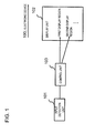
- the electronic device 100 comprises an input detection unit 101 that detects a contact operation or a proximity operation performed by the user; a display unit 102 that includes a first display region displaying a first image showing a position where a first operation is received; and a control unit 103 that changes display mode of the first display region based on a second operation when the input detection unit 101 detects the second operation and that has a second image displayed in a second display region where a third operation is received.
- the electronic device 100 is capable of receiving operations independent from each other for a plurality of display regions. For instance, let's assume that a software keyboard (the first image) that receives an input operation (the first operation) is displayed in the first display region on the electronic device 100. In this case, while displaying the software keyboard based on one operation (the second operation), the electronic device 100 is able to display an image that receives another operation (the third operation). At this time, the electronic device 100 changes the display mode (the image size, etc.) of the software keyboard. Therefore, the electronic device 100 contributes to facilitating an operation independent from the software keyboard while the software keyboard is being used.
- Fig. 2 is a plan view showing an example of the overall configuration of an electronic device 1 relating to the present exemplary embodiment.
- the electronic device 1 is constituted by including a liquid crystal panel 20 and a touch panel 30.
- the touch panel 30 is integrated into the liquid crystal panel 20.
- the liquid crystal panel 20 may be a different display device such as an organic EL (Electro Luminescence) panel.
- organic EL Electro Luminescence
- the touch panel 30 is a touch panel that detects with a sensor on a flat surface a contact operation or a proximity operation performed by the user.
- touch panel methods such as an electrostatic capacitance method, but any method can be used.
- the touch panel 30 is able to detect a plurality of contact points or proximity points simultaneously, i.e., a multi-point input (referred to as "multi-touch” hereinafter).
- the electronic device 1 can take any form as long as it comprises the device shown in Fig. 2 .
- a smartphone, portable audio device, PDA (Personal Digital Assistant), game device, tablet PC (Personal Computer), note PC, and electronic book reader correspond to the electronic device 1 of the present exemplary embodiment.
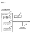
- Fig. 3 is a drawing showing an example of the internal configuration of the electronic device 1.
- the electronic device 1 is constituted by including a control unit 10, the liquid crystal panel 20, and the touch panel 30.
- the control unit 10 includes an input determination unit 11, a display region control unit 12, and an image signal generation unit 13.
- Fig. 3 only shows modules relevant to the electronic device 1 relating to the present exemplary embodiment.
- the input determination unit 11 determines the detected positions and detected number of inputs detected by the touch panel 30. Further, the input determination unit 11 determines the type of a detected input operation.
- the input operation types include single tap operation, double tap operation, etc. In a single tap operation, the user lifts his finger off the surface immediately after touching (or getting close to) the surface of the touch panel 30. In a double tap operation, the user performs single tap operations twice continuously.
- the input operation types also include so-called slide operation and flick operation.
- slide operation the user moves his finger across the touch panel 30 for a predetermined period of time or longer, and lifts the finger after moving it over a predetermined distance or more.
- the input determination unit 11 determines that a slide operation has been performed.
- the user flicks his finger against the surface of the touch panel 30.
- the input determination unit 11 determines that a flick operation has been performed.
- the display region control unit 12 generates a plurality of display regions where images are displayed.
- the image signal generation unit 13 generates the image signal of an image related to an application for the generated display region. For the sake of simplicity, the generation of an image signal by the image signal generation unit 13 is described as the display of an image hereinafter.
- Fig. 4 is a drawing showing a display example of the liquid crystal panel 20.
- a Web browser is launched and search results are shown. Further, a software keyboard is displayed to enter characters in Fig. 4 .
- the software keyboard corresponds to the first image described above. Further, a display region displaying the software keyboard corresponds to the first display region described above. Moreover, an operation to enter characters on the software keyboard is the first operation described above.
- the display region control unit 12 changes the size and position of the first display region.
- the second operation is referred to as multi-screen transition operation hereinafter. More concretely, the display region control unit 12 reduces the first display region according to the multi-screen transition operation. Then, the image signal generation unit 13 displays the software keyboard in the reduced first display region. Further, the image signal generation unit 13 displays an image of a second application in a region (referred to as the second display region hereinafter) made available due to the reduction of the first display region.
- the display region control unit 12 changes the position of the software keyboard according to the direction of the multi-screen transition operation. More concretely, the display region control unit 12 moves the first display region in the direction in which the detected position of the multi-screen transition operation moved.
- the display region control unit 12 moves the first display region to a position within a predetermined range. Then the image signal generation unit 13 displays the software keyboard in the relocated first display region.
- the display region control unit 12 reduces the first display region and moves it to a position where the detected input position stopped. Then the image signal generation unit 13 displays the software keyboard in the relocated first display region. In other words, the display region control unit 12 reduces and displays the software keyboard according to the position where the user stopped his finger after performing a slide operation.
- the display region control unit 12 reduce and move the first display region so as to be able to put a side of the first display region against a side of the outer frame of the liquid crystal panel 20 closest to the direction of the multi-screen transition operation. Further, it is preferred that the display region control unit 12 move the center of the first display region in the direction of the side of the outer frame of the liquid crystal panel 20 closest to the direction of the multi-screen transition operation.
- the display region control unit 12 reduce and move the first display region so as to be able to fix a vertex of the first display region at a vertex of the outer frame of the liquid crystal panel 20 closest to the direction of the multi-screen transition operation. Further, it is preferred that the display region control unit 12 move the center of the first display region in the direction of the vertex of the outer frame of the liquid crystal panel 20 closest to the direction of the multi-screen transition operation.
- Figs. 5A and 5B show an example of a display mode of the software keyboard.
- Points P401 to P404 in Figs. 5A and 5B represent positions where the touch panel 30 detects inputs.
- the software keyboard is displayed as shown in Fig. 5A
- the touch panel 30 detects an input at the point P401.
- the user performs a slide operation to the position of the point P402 shown in Fig. 5B and stops his finger at the position of the point P402.
- the position of the input detected by the touch panel 30 stops at the position of the point P402.
- the direction from the point P401 to the point P402 is assumed to be a direction with a range exceeding a predetermined angle in relation to the horizontal and vertical directions.
- the vertex at the lower left corner of the outer frame of the liquid crystal panel 20 is closest to the point P402. Therefore, the display region control unit 12 reduces and moves the first display region so as to fix the lower left vertex of the first display region at the lower left vertex of the outer frame of the liquid crystal panel 20.
- the image signal generation unit 13 displays the software keyboard in the relocated first display region. In other words, as shown in Fig. 5B , the image signal generation unit 13 displays the software keyboard in the lower left corner of the liquid crystal panel 20. Further, although this is not shown in the drawings, the image signal generation unit 13 displays an image of a second application in the display region made available by moving the software keyboard.
- the direction from the point P401 to the point P403 is assumed to be a direction with a range exceeding a predetermined angle in relation to the horizontal and vertical directions.
- the vertex at the lower right corner of the outer frame of the liquid crystal panel 20 is closest to the point P403. Therefore, the display region control unit 12 reduces and moves the first display region so as to fix the lower right vertex of the first display region at the lower right vertex of the outer frame of the liquid crystal panel 20.
- the image signal generation unit 13 displays the software keyboard in the relocated first display region. In other words, the image signal generation unit 13 displays the software keyboard in the lower right corner of the liquid crystal panel 20.
- the direction from the point P401 to the point P404 is assumed to be the direction of an angle within a predetermined range in relation to the vertical direction.
- the upper side of the outer frame of the liquid crystal panel 20 is a side closest to the direction from the point P401 to the point P404. Therefore, the display region control unit 12 reduces and moves the first display region so as to put the upper side of the first display region against the upper side of the outer frame of the liquid crystal panel 20. Then the image signal generation unit 13 displays the software keyboard in the relocated first display region. In other words, the image signal generation unit 13 displays the software keyboard in the upper area of the liquid crystal panel 20.
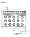
- Fig. 6 is a drawing showing an example in which a screen that displays icons and menus for running applications (referred to as the home screen hereinafter) and the software keyboard are displayed.
- the image signal generation unit 13 displays the software keyboard with its size reduced in the upper area of the liquid crystal panel 20.
- the region made available by reducing the software keyboard is a second display region 202.
- the image signal generation unit 13 displays the home screen in the second display region 202.
- the electronic device 1 relating to the present exemplary embodiment is able to display a second application such as an address book application while having a first application such as a Web browser displayed.
- Fig. 7 is a drawing showing an example in which different applications are displayed in a plurality of display regions.
- the software keyboard is reduced and displayed in a first display region 201.
- an address book application is displayed in the second display region 202 in Fig. 7 .
- the display region control unit 12 may switch the display modes of the first and second display regions. More concretely, according to a predetermined operation, the display region control unit 12 may enlarge the reduced first display region and reduce the second display region.
- the predetermined operation that switches the display modes be a simple and easy operation such as a double tap operation.
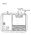
- Fig. 8 is a drawing showing an example in which the display modes are switched.
- the display of the software keyboard is enlarged and displayed in the first display region 201.
- the address book application is reduced and displayed in the second display region 202.
- the image signal generation unit 13 may have a third application displayed while displaying the images of two different applications. More concretely, when detecting a fourth operation in the second display region, the display region control unit 12 reduces and moves the second display region. It is preferred that the fourth operation be a simple and easy operation such as a double tap or flick operation.
- the image signal generation unit 13 displays the image of the third application in a region (a third region) made available by reducing the second display region. As described, the electronic device 1 relating to the present exemplary embodiment does not limit the number of applications displayed simultaneously.
- Fig. 9 is a drawing showing an example in which the image of the third application is displayed on the liquid crystal panel 20.
- the software keyboard is displayed in the first display region 201.
- the address book application is displayed in the second display region 202.
- an email application is displayed in a third display region 203.
- an operation to cancel a multi-screen display be simply and easy.
- the input determination unit 11 may determine whether or not to cancel a multi-screen display depending on the presence of an input in the first display region.
- the image signal generation unit 13 displays images in the first and second display regions. Then the control unit 10 executes processing on the second display region according to an operation thereon.
- the touch panel 30 detects a multi-touch.
- the touch panel 30 is able to detect inputs on the first and second display regions simultaneously. Therefore, the user can perform an operation on the second display region while contacting (being close to) the first display region.
- the display region control unit 12 stops displaying the second display region. Further, when the touch panel 30 stops detecting any input in the first display region, the display region control unit 12 enlarges the display of the first display region. In other words, when the user lifts his fingers that were in contact with (close to) the first display region, the display of the first display region is enlarged. At this time, the size of the first display region may be returned to the original one before the reduction.
- the operation to hide the second display region and enlarge the display of the first display region is referred to as multi-screen cancellation operation.
- Fig. 10 is a flowchart showing an operation example of the electronic device 1 relating to the present exemplary embodiment.
- step S1 the control unit 10 determines whether or not the software keyboard is displayed. When the software keyboard is displayed (Yes in the step S1), the process proceeds to step S2. When the software keyboard is not displayed (No in the step S1), the process returns to the step S1 and the processing is continued.
- the input determination unit 11 determines whether or not the touch panel 30 detects a multi-screen transition operation.
- the process proceeds to step S3.
- no multi-screen transition operation is detected (No in the step S2), the process returns to the step S2 and the processing is continued.
- the display region control unit 12 reduces and moves the first display region according to the direction in which the detected position of the multi-screen transition operation changed and to the distance of the change. More concretely, the display region control unit 12 may reduce the first display region so as to put it against the outer frame of the liquid crystal panel 20. Or the display region control unit 12 may reduce the first display region while fixing a vertex (corner) thereof. In this case, it is preferred that the display region control unit 12 fix a vertex out of those of the first display region closest to the direction in which the detected position of the multi-screen transition operation changed. Further, it is preferred that the display region control unit 12 move the center of the first display region when reducing it.
- step S4 the image signal generation unit 13 displays the home screen in the second display region.
- step S5 the input determination unit 11 determines whether or not the input of the multi-screen transition operation is continuously detected. When the input is continuously detected (Yes in the step S5), the process proceeds to step S6. When the input is not detected (No in the step S5), the process proceeds to step S7.
- the input determination unit 11 determines whether or not the touch panel 30 detects any input in the second display region. When an input is detected in the second display region (Yes in the step S6), the process proceeds to step S8. When no input is detected in the second display region (No in the step S6), the process returns to the step S5 and the processing is continued.
- the second display region is reduced or hidden, and the first display region is enlarged.
- the first display region may be restored to its original size and returned to its original position before the reduction.
- control unit 10 performs processing such as launching a second application according to the input detected in the second display region.
- the process returns to the step S5 and the processing is continued.
- Figs. 11A and 11B are drawings showing display examples of the second display region.
- the software keyboard is displayed in the first display region 201.
- the first display region 201 occupies the entire screen of the liquid crystal panel 20 in Fig. 11A .
- the touch panel 30 has detected an input at the position of a point P411 in the state of Fig. 11A and then the detected position has moved in the direction of an arrow D1. In other words, the user has performed a flick or slide operation from the point P411 in the direction of the arrow D1.
- the display region control unit 12 reduces the first display region 201.
- the image signal generation unit 13 reduces and displays the software keyboard in the reduced first display region 201.
- a point P412 denotes the position where the movement of the detected position has stopped.
- P412 is the position where the touch panel 30 has detected an input within the first display region within a predetermined period of time after the flick operation.
- the image signal generation unit 13 displays the image of a second application in the second display region 202.
- the image signal generation unit 13 displays the home screen in the second display region 202.
- the control unit 10 performs processing according to an input on the second display region. For instance, let's assume that the touch panel detects an input at the position of an icon 501 (the position of a point P413) in the second display region in Fig. 11B . In this case, the control unit 10 performs processing according to the input on the icon 501.
- the touch panel 30 detects a tap operation on an icon that launches an application in the second display region 202.
- the image signal generation unit 13 displays the image of the selected application in the second display region 202. Further, at this time, the image signal generation unit 13 continues to display the image in the first display region 201.
- the input determination unit 11 may disable the multi-screen cancellation operation for a predetermined period of time after a multi-screen transition operation. For instance, there is a possibility that the user lifts his finger from the first display region on the touch panel 30 immediately after he performs a slide operation as a multi-screen transition operation. In this case, despite the multi-screen transition operation performed by the user, the display immediately returns to the state in which the first display region is enlarged. Therefore, it is preferred that the display region control unit 12 should not enlarge the first display region for a predetermined period of time after reducing the first display region.
- the user can change the finger for touching (getting close to) the first display region for a predetermined period of time after the first display region is reduced. For instance, let's say that he performed a multi-screen transition operation with his right index finger. The user is able to change the finger for touching (getting close to) the first display region to his left thumb for a predetermined period of time.
- the electronic device 1 relating to the present exemplary embodiment is able to display images of a plurality of applications simultaneously. Further, with the electronic device 1 relating to the present exemplary embodiment, while the software keyboard is being used, an operation on another application can be performed. Therefore, with the electronic device 1 relating to the present exemplary embodiment, an operation independent from the software keyboard can be easily performed while the software keyboard is being used.
- An electronic device 1 relating to the present exemplary embodiment changes the size and position of a software keyboard without displaying a plurality of applications. Note that the description that overlaps with the first exemplary embodiment will be omitted in the description of the present exemplary embodiment. Further, the same signs are given to the elements same as those in the first exemplary embodiment and the explanation thereof will be omitted in the description of the present exemplary embodiment.
- the image signal generation unit 13 changes the position of the software keyboard.
- a region in which the software keyboard is displayed is the first display region.
- a region excluding the software keyboard is the second display region. Note that the description of the operation to restore the display modes of the first and second display regions (corresponding to the multi-screen cancellation operation) will be omitted since it is the same as that of the electronic device 1 relating to the first exemplary embodiment.
- Figs. 12A and 12B are drawings showing display examples of the liquid crystal panel 20.
- Fig. 12B shows an example in which the software keyboard is moved down from a state shown in Fig. 12A .
- the electronic device 1 relating to the present exemplary embodiment lowers the position of the software keyboard.
- the second display region 212 is enlarged due to the fact that the first display region 211 is reduced.
- the electronic device 1 relating to the present exemplary embodiment is able to move the display of the software keyboard and enlarge the display region of search results based on a simple and easy operation.
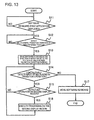
- Fig. 13 is a flowchart showing an operation example of the electronic device 1 relating to the present exemplary embodiment. Note that steps S11 and S12 are the same as the steps S1 and S2, respectively, and the explanation will be omitted.
- step S13 the display region control unit 12 moves the first display region in the direction in which the detected position of a multi-screen transition operation moved.
- the software keyboard is displayed as if a part thereof goes off the screen with only the remaining part displayed.
- step S14 the input determination unit 11 determines whether or not the touch panel 30 continuously detects the input of the multi-screen transition operation. When the input is continuously detected (Yes in the step S14), the process proceeds to step S15. When the input is not detected (No in the step S14), the process proceeds to step S17.
- step S15 the input determination unit 11 determines whether or not the touch panel 30 detects any input in the second display region.
- the process proceeds to step S16.
- no input is detected in the second display region (No in the step S15)
- the process returns to the step S14 and the processing is continued.
- step S16 the control unit 10 performs processing according to the input detected in the second display region. Then the process returns to the step S14 and the processing is continued.
- the control unit 10 enlarges the first display region.
- the first display region may be restored to its original size and the software keyboard may be returned to its original position.
- Figs. 14A and 14B are drawings showing an example of how the display mode of the software keyboard changes.
- a Web browser is displayed on the liquid crystal panel 20 as a first application.
- the software keyboard is displayed on the liquid crystal panel 20 in Fig. 14A .
- the touch panel 30 detects an input (detects a multi-screen transition operation) at the position of a predetermined point P421 of the software keyboard and the detected position of the multi-screen transition operation moves in the direction of an arrow D2.
- the display region control unit 12 reduces the first display region in the direction of the arrow D2 as shown in Fig. 14B .
- the image signal generation unit 13 moves the software keyboard to the first display region and displays it therein.
- the control unit 10 performs processing according to an input at a point P422. For instance, the control unit executes processing such as scrolling the Web browser screen, selecting a region, etc. according to the input at the point P422.
- the electronic device 1 relating to the present exemplary embodiment changes the position of the software keyboard.
- the electronic device 1 relating to the present exemplary embodiment is able to perform an operation independent from the software keyboard while the software keyboard is being used by an application.
- the software keyboard is reduced and displayed near a position where the touch panel has detected an input.
- the description that overlaps with the first exemplary embodiment will be omitted in the description of the present exemplary embodiment. Further, the same signs are given to the elements same as those in the first exemplary embodiment and the explanation thereof will be omitted in the description of the present exemplary embodiment.
- the image signal generation unit 13 reduces the software keyboard and displays it near the position where the input is detected. More concretely, the image signal generation unit 13 reduces the software keyboard and displays it within a predetermined range based on the position where a multi-screen transition operation has been detected. In other words, the display region control unit 12 changes the display mode of a display region based on a contact (proximity) operation at one place.
- Figs. 15A and 15B are drawings showing display examples of the liquid crystal panel 20.
- first and second display regions 221 and 222 are displayed on the screen.
- a reduced software keyboard is displayed in the first display region 221.
- the second display region 222 displays the home screen.
- the touch panel 30 detects an input at the position of a point P431 in Fig. 15A .
- the display region control unit 12 reduces the first display region and moves it to a position near the point P431.
- the moved first display region is referred to as a first region 223.
- the point P431 becomes the center of the software keyboard and the software keyboard is reduced to a size that does not go off the screen of the liquid crystal panel, but the present exemplary embodiment is not limited thereto.
- the image signal generation unit 13 displays the software keyboard in the first display region 223.
- the display region control unit 12 further reduces the first display region from the state of the first display region 221 shown in Fig. 15A .
- the display region control unit 12 enlarges the size of the second display region.
- the image signal generation unit 13 enlarges the display of the home screen. Further, when the touch panel 30 stops detecting any input at the point P431, the display region control unit 12 returns the display mode of the display regions to the state shown in Fig. 15A .
- the electronic device 1 relating to the present exemplary embodiment reduces the software keyboard and displays it near the position where the touch panel has detected an input. Therefore, in the electronic device 1 relating to the present exemplary embodiment, the display regions of the home screen and an application launched by selecting the icon thereof on the home screen will be larger. As a result, the electronic device 1 relating to the present exemplary embodiment facilitates the user to operate a running application, offering even more user-friendliness.
Landscapes
- Engineering & Computer Science (AREA)
- Theoretical Computer Science (AREA)
- General Engineering & Computer Science (AREA)
- Human Computer Interaction (AREA)
- Physics & Mathematics (AREA)
- General Physics & Mathematics (AREA)
- User Interface Of Digital Computer (AREA)
- Input From Keyboards Or The Like (AREA)
Abstract
Description
- This application is based upon and claims the benefit of the priority of Japanese Patent Application No.
2012-130755 filed on June 8, 2012 - The present invention relates to an electronic device and controlling method and program therefor, and particularly to an electronic device comprising a touch panel and a controlling method and program therefor.
- In recent years, an electronic device comprising a touch panel often has a liquid crystal panel and the touch panel integrated. Such an electronic device often comprises a software keyboard displayed by software. However, depending on its size or position, the software keyboard may interfere with the user's operation.
-
Patent Literature 1 discloses a technology that controls the size of a software keyboard according to a user's operation. - Patent Literature 2 discloses a technology that displays a software keyboard while dividing the image thereof according to a user's operation.
-
-
Patent Literature 1 Japanese Patent Kokai Publication No.JP2009-122890A - Patent Literature 2 Japanese Patent Kokai Publication No.
JP2010-134625A - As described above, a software keyboard may interfere with the user's operation, depending on its size or position. In particular, with a small device such as a smartphone, a software keyboard sometimes occupies one half of the display screen area.
- For instance, let's assume a case where a user is performing a more detailed search based on search results using a Web browser. At this time, if the area of the software keyboard is large, it may be difficult for the user to perform an input operation while browsing the search results.
- Further, for instance, let's assume a case where a user launches a Web browser and refers to information regarding the people registered in an address book in the middle of his input operation. In this case, the user first quits the Web browser currently running. Then, he launches the address book application. After confirming the information, the user quits the address book application. Then, after launching the Web browser again, the user has a software keyboard displayed to enter the information. As described, the user must perform a plurality of operations when he refers to information included in another application while using the software keyboard.
- The technologies disclosed in
Patent Literatures 1 and 2 do not allow a user to refer to information included in another application while using a software keyboard. - Therefore, an electronic device contributing to facilitating an operation independent from a software keyboard while the software keyboard is being used, and a controlling method and program therefor are desired.
- According to a first aspect, there is provided an electronic device comprising an input detection unit that detects a contact operation or a proximity operation performed by a user; a display unit that includes a first display region displaying a first image showing a position where a first operation is received; and a control unit that changes display mode of the first display region based on a second operation when the input detection unit detects the second operation and that has a second image displayed in a second display region where a third operation is received.
- According to a second aspect, there is provided a controlling method for an electronic device comprising a display unit that includes a first display region, and the controlling method comprises a step of detecting a contact operation or a proximity operation performed by a user; a step of displaying a first image that shows a position where a first operation is received in the first display region; and a control step of changing display mode of the first display region based on a second operation when the second operation is detected and having a second image displayed in a second display region where a third operation is received.
- Further, the present method is associated with a particular machine, which is an electronic device comprising a display unit.
- According to a third aspect, there is provided a program executed by a computer that controls an electronic device comprising a display unit that includes a first display region, and the program executes a process of detecting a contact operation or a proximity operation performed by a user; a process of displaying a first image that shows a position where a first operation is received in the first display region; and a control process of changing display mode of the first display region based on a second operation when the second operation is detected and having a second image displayed in a second display region where a third operation is received.
- Further, this program can be stored in a computer-readable storage medium. The storage medium can be a non-transient one such as a semiconductor memory, hard disk, magnetic storage medium, and optical storage medium. The present invention can be embodied as a computer program product.
- According to each aspect of the present invention, an electronic device contributing to facilitating an operation independent from a software keyboard while the software keyboard is being used, and a controlling method and program therefor are provided.
-
-
Fig. 1 is a drawing for explaining an exemplary embodiment. -
Fig. 2 is a plan view showing an example of the overall configuration of anelectronic device 1 relating to a first exemplary embodiment. -
Fig. 3 is a drawing showing an example of the internal configuration of theelectronic device 1. -
Fig. 4 is a drawing showing a display example of aliquid crystal panel 20. -
Figs. 5A and 5B are drawings showing display mode examples of a software keyboard. -
Fig. 6 is a drawing showing a display example of theliquid crystal panel 20. -
Fig. 7 is a drawing showing a display example of theliquid crystal panel 20. -
Fig. 8 is a drawing showing a display example of theliquid crystal panel 20. -
Fig. 9 is a drawing showing a display example of theliquid crystal panel 20. -
Fig. 10 is a flowchart showing an operation example of theelectronic device 1 relating to the first exemplary embodiment. -
Figs. 11A and 11B are drawings showing display examples of theliquid crystal panel 20. -
Figs. 12A and 12B are drawings showing display examples of theliquid crystal panel 20. -
Fig. 13 is a flowchart showing an operation example of anelectronic device 1 relating to a second exemplary embodiment. -
Figs. 14A and 14B are drawings showing display examples of theliquid crystal panel 20. -
Figs. 15A and 15B are drawings showing display examples of theliquid crystal panel 20. - First, a summary of an exemplary embodiment of the present invention will be given using
Fig. 1 . Note that drawing reference signs in the summary are given to each element for convenience as examples solely for facilitating understanding, and the description of the summary is not intended to suggest any limitation. - As described above, when performing an input operation on a software keyboard, a user sometimes refers to information included in another application. Therefore, an electronic device that enables the user to easily perform an operation independent from the software keyboard while using the software keyboard is desired.
- An
electronic device 100 shown inFig. 1 is provided as an example. Theelectronic device 100 comprises aninput detection unit 101 that detects a contact operation or a proximity operation performed by the user; adisplay unit 102 that includes a first display region displaying a first image showing a position where a first operation is received; and acontrol unit 103 that changes display mode of the first display region based on a second operation when theinput detection unit 101 detects the second operation and that has a second image displayed in a second display region where a third operation is received. - The
electronic device 100 is capable of receiving operations independent from each other for a plurality of display regions. For instance, let's assume that a software keyboard (the first image) that receives an input operation (the first operation) is displayed in the first display region on theelectronic device 100. In this case, while displaying the software keyboard based on one operation (the second operation), theelectronic device 100 is able to display an image that receives another operation (the third operation). At this time, theelectronic device 100 changes the display mode (the image size, etc.) of the software keyboard. Therefore, theelectronic device 100 contributes to facilitating an operation independent from the software keyboard while the software keyboard is being used. - Concrete exemplary embodiments will be described below in more detail with reference to the drawings.
- A first exemplary embodiment will be described in more detail with reference to the drawings.
-
Fig. 2 is a plan view showing an example of the overall configuration of anelectronic device 1 relating to the present exemplary embodiment. - The
electronic device 1 is constituted by including aliquid crystal panel 20 and atouch panel 30. Thetouch panel 30 is integrated into theliquid crystal panel 20. - Further, the
liquid crystal panel 20 may be a different display device such as an organic EL (Electro Luminescence) panel. There are various color gradations for display devices, but any implementation method may be used for theelectronic device 1 relating to the present exemplary embodiment. - Further, the
touch panel 30 is a touch panel that detects with a sensor on a flat surface a contact operation or a proximity operation performed by the user. There are various touch panel methods such as an electrostatic capacitance method, but any method can be used. Further, thetouch panel 30 is able to detect a plurality of contact points or proximity points simultaneously, i.e., a multi-point input (referred to as "multi-touch" hereinafter). - The
electronic device 1 can take any form as long as it comprises the device shown inFig. 2 . For instance, a smartphone, portable audio device, PDA (Personal Digital Assistant), game device, tablet PC (Personal Computer), note PC, and electronic book reader correspond to theelectronic device 1 of the present exemplary embodiment. -
Fig. 3 is a drawing showing an example of the internal configuration of theelectronic device 1. Theelectronic device 1 is constituted by including acontrol unit 10, theliquid crystal panel 20, and thetouch panel 30. Thecontrol unit 10 includes aninput determination unit 11, a displayregion control unit 12, and an imagesignal generation unit 13. For the sake of simplicity,Fig. 3 only shows modules relevant to theelectronic device 1 relating to the present exemplary embodiment. - The
input determination unit 11 determines the detected positions and detected number of inputs detected by thetouch panel 30. Further, theinput determination unit 11 determines the type of a detected input operation. The input operation types include single tap operation, double tap operation, etc. In a single tap operation, the user lifts his finger off the surface immediately after touching (or getting close to) the surface of thetouch panel 30. In a double tap operation, the user performs single tap operations twice continuously. - The input operation types also include so-called slide operation and flick operation. In a slide operation, the user moves his finger across the
touch panel 30 for a predetermined period of time or longer, and lifts the finger after moving it over a predetermined distance or more. In other words, when thetouch panel 30 detects an input lasting for a predetermined period of time or longer and moving over a predetermined distance or more, theinput determination unit 11 determines that a slide operation has been performed. - Further, in a flick operation, the user flicks his finger against the surface of the
touch panel 30. In other words, when thetouch panel 30 detects an input moving less than a predetermined distance within a predetermined period of time, theinput determination unit 11 determines that a flick operation has been performed. - The display
region control unit 12 generates a plurality of display regions where images are displayed. The imagesignal generation unit 13 generates the image signal of an image related to an application for the generated display region. For the sake of simplicity, the generation of an image signal by the imagesignal generation unit 13 is described as the display of an image hereinafter. -
Fig. 4 is a drawing showing a display example of theliquid crystal panel 20. InFig. 4 , a Web browser is launched and search results are shown. Further, a software keyboard is displayed to enter characters inFig. 4 . - Here, the software keyboard corresponds to the first image described above. Further, a display region displaying the software keyboard corresponds to the first display region described above. Moreover, an operation to enter characters on the software keyboard is the first operation described above.
- First, a process of displaying images of different applications in a plurality of display regions will be described. In the description below, the process of displaying images of different applications in a plurality of display regions will be referred to as multi-screen display.
- When the
touch panel 30 detects a predetermined operation (corresponding to the second operation described above) at a predetermined position, the displayregion control unit 12 changes the size and position of the first display region. The second operation is referred to as multi-screen transition operation hereinafter. More concretely, the displayregion control unit 12 reduces the first display region according to the multi-screen transition operation. Then, the imagesignal generation unit 13 displays the software keyboard in the reduced first display region. Further, the imagesignal generation unit 13 displays an image of a second application in a region (referred to as the second display region hereinafter) made available due to the reduction of the first display region. - Further, the display
region control unit 12 changes the position of the software keyboard according to the direction of the multi-screen transition operation. More concretely, the displayregion control unit 12 moves the first display region in the direction in which the detected position of the multi-screen transition operation moved. - Here, if a flick operation is detected as a multi-screen transition operation, the display
region control unit 12 moves the first display region to a position within a predetermined range. Then the imagesignal generation unit 13 displays the software keyboard in the relocated first display region. - If a slide operation is detected as a multi-screen transition operation, the display
region control unit 12 reduces the first display region and moves it to a position where the detected input position stopped. Then the imagesignal generation unit 13 displays the software keyboard in the relocated first display region. In other words, the displayregion control unit 12 reduces and displays the software keyboard according to the position where the user stopped his finger after performing a slide operation. - First, a case where the direction of the multi-screen transition operation is the direction of an angle within a predetermined range in relation to the horizontal or vertical direction will be described. In this case, it is preferred that the display
region control unit 12 reduce and move the first display region so as to be able to put a side of the first display region against a side of the outer frame of theliquid crystal panel 20 closest to the direction of the multi-screen transition operation. Further, it is preferred that the displayregion control unit 12 move the center of the first display region in the direction of the side of the outer frame of theliquid crystal panel 20 closest to the direction of the multi-screen transition operation. - Next, a case where the direction of the multi-screen transition operation is a direction with a range exceeding a predetermined angle in relation to the horizontal and vertical directions will be described. In this case, it is preferred that the display
region control unit 12 reduce and move the first display region so as to be able to fix a vertex of the first display region at a vertex of the outer frame of theliquid crystal panel 20 closest to the direction of the multi-screen transition operation. Further, it is preferred that the displayregion control unit 12 move the center of the first display region in the direction of the vertex of the outer frame of theliquid crystal panel 20 closest to the direction of the multi-screen transition operation. -
Figs. 5A and 5B show an example of a display mode of the software keyboard. Points P401 to P404 inFigs. 5A and 5B represent positions where thetouch panel 30 detects inputs. First, let's assume that the software keyboard is displayed as shown inFig. 5A , and thetouch panel 30 detects an input at the point P401. Then the user performs a slide operation to the position of the point P402 shown inFig. 5B and stops his finger at the position of the point P402. In other words, the position of the input detected by thetouch panel 30 stops at the position of the point P402. Here, the direction from the point P401 to the point P402 is assumed to be a direction with a range exceeding a predetermined angle in relation to the horizontal and vertical directions. Further, the vertex at the lower left corner of the outer frame of theliquid crystal panel 20 is closest to the point P402. Therefore, the displayregion control unit 12 reduces and moves the first display region so as to fix the lower left vertex of the first display region at the lower left vertex of the outer frame of theliquid crystal panel 20. Then the imagesignal generation unit 13 displays the software keyboard in the relocated first display region. In other words, as shown inFig. 5B , the imagesignal generation unit 13 displays the software keyboard in the lower left corner of theliquid crystal panel 20. Further, although this is not shown in the drawings, the imagesignal generation unit 13 displays an image of a second application in the display region made available by moving the software keyboard. - Next, a case where the user performs a slide operation in the direction from the point P401 to the point P403 will be discussed. Here, the direction from the point P401 to the point P403 is assumed to be a direction with a range exceeding a predetermined angle in relation to the horizontal and vertical directions. Further, the vertex at the lower right corner of the outer frame of the
liquid crystal panel 20 is closest to the point P403. Therefore, the displayregion control unit 12 reduces and moves the first display region so as to fix the lower right vertex of the first display region at the lower right vertex of the outer frame of theliquid crystal panel 20. Then the imagesignal generation unit 13 displays the software keyboard in the relocated first display region. In other words, the imagesignal generation unit 13 displays the software keyboard in the lower right corner of theliquid crystal panel 20. - Further, a case where the user performs a slide operation in the direction from the point P401 to the point P404 will be discussed. Here, the direction from the point P401 to the point P404 is assumed to be the direction of an angle within a predetermined range in relation to the vertical direction. Further, the upper side of the outer frame of the
liquid crystal panel 20 is a side closest to the direction from the point P401 to the point P404. Therefore, the displayregion control unit 12 reduces and moves the first display region so as to put the upper side of the first display region against the upper side of the outer frame of theliquid crystal panel 20. Then the imagesignal generation unit 13 displays the software keyboard in the relocated first display region. In other words, the imagesignal generation unit 13 displays the software keyboard in the upper area of theliquid crystal panel 20. -
Fig. 6 is a drawing showing an example in which a screen that displays icons and menus for running applications (referred to as the home screen hereinafter) and the software keyboard are displayed. InFig. 6 , the imagesignal generation unit 13 displays the software keyboard with its size reduced in the upper area of theliquid crystal panel 20. Here, the region made available by reducing the software keyboard is asecond display region 202. InFig. 6 , the imagesignal generation unit 13 displays the home screen in thesecond display region 202. - As described, the
electronic device 1 relating to the present exemplary embodiment is able to display a second application such as an address book application while having a first application such as a Web browser displayed. -
Fig. 7 is a drawing showing an example in which different applications are displayed in a plurality of display regions. InFig. 7 , the software keyboard is reduced and displayed in afirst display region 201. Further, an address book application is displayed in thesecond display region 202 inFig. 7 . - The display
region control unit 12 may switch the display modes of the first and second display regions. More concretely, according to a predetermined operation, the displayregion control unit 12 may enlarge the reduced first display region and reduce the second display region. Here, it is preferred that the predetermined operation that switches the display modes be a simple and easy operation such as a double tap operation. -
Fig. 8 is a drawing showing an example in which the display modes are switched. InFig. 8 , the display of the software keyboard is enlarged and displayed in thefirst display region 201. Further, the address book application is reduced and displayed in thesecond display region 202. - The image
signal generation unit 13 may have a third application displayed while displaying the images of two different applications. More concretely, when detecting a fourth operation in the second display region, the displayregion control unit 12 reduces and moves the second display region. It is preferred that the fourth operation be a simple and easy operation such as a double tap or flick operation. The imagesignal generation unit 13 displays the image of the third application in a region (a third region) made available by reducing the second display region. As described, theelectronic device 1 relating to the present exemplary embodiment does not limit the number of applications displayed simultaneously. -
Fig. 9 is a drawing showing an example in which the image of the third application is displayed on theliquid crystal panel 20. InFig. 9 , the software keyboard is displayed in thefirst display region 201. Further, the address book application is displayed in thesecond display region 202. Then, an email application is displayed in athird display region 203. - Next, a process of canceling a multi-screen display will be described.
- It is preferred that an operation to cancel a multi-screen display be simply and easy. For instance, the
input determination unit 11 may determine whether or not to cancel a multi-screen display depending on the presence of an input in the first display region. In other words, when thetouch panel 30 continues to detect inputs in the first display region, the imagesignal generation unit 13 displays images in the first and second display regions. Then thecontrol unit 10 executes processing on the second display region according to an operation thereon. - Here, as described above, the
touch panel 30 detects a multi-touch. In other words, thetouch panel 30 is able to detect inputs on the first and second display regions simultaneously. Therefore, the user can perform an operation on the second display region while contacting (being close to) the first display region. - Then, when the
touch panel 30 stops detecting any input in the first display region, the displayregion control unit 12 stops displaying the second display region. Further, when thetouch panel 30 stops detecting any input in the first display region, the displayregion control unit 12 enlarges the display of the first display region. In other words, when the user lifts his fingers that were in contact with (close to) the first display region, the display of the first display region is enlarged. At this time, the size of the first display region may be returned to the original one before the reduction. In the description below, the operation to hide the second display region and enlarge the display of the first display region is referred to as multi-screen cancellation operation. - Next, the operation of the
electronic device 1 relating to the present exemplary embodiment will be described. -
Fig. 10 is a flowchart showing an operation example of theelectronic device 1 relating to the present exemplary embodiment. - In step S1, the
control unit 10 determines whether or not the software keyboard is displayed. When the software keyboard is displayed (Yes in the step S1), the process proceeds to step S2. When the software keyboard is not displayed (No in the step S1), the process returns to the step S1 and the processing is continued. - In the step S2, the
input determination unit 11 determines whether or not thetouch panel 30 detects a multi-screen transition operation. When a multi-screen transition operation is detected (Yes in the step S2), the process proceeds to step S3. When no multi-screen transition operation is detected (No in the step S2), the process returns to the step S2 and the processing is continued. - In step S3, the display
region control unit 12 reduces and moves the first display region according to the direction in which the detected position of the multi-screen transition operation changed and to the distance of the change. More concretely, the displayregion control unit 12 may reduce the first display region so as to put it against the outer frame of theliquid crystal panel 20. Or the displayregion control unit 12 may reduce the first display region while fixing a vertex (corner) thereof. In this case, it is preferred that the displayregion control unit 12 fix a vertex out of those of the first display region closest to the direction in which the detected position of the multi-screen transition operation changed. Further, it is preferred that the displayregion control unit 12 move the center of the first display region when reducing it. - In step S4, the image
signal generation unit 13 displays the home screen in the second display region. - In step S5, the
input determination unit 11 determines whether or not the input of the multi-screen transition operation is continuously detected. When the input is continuously detected (Yes in the step S5), the process proceeds to step S6. When the input is not detected (No in the step S5), the process proceeds to step S7. - In the step S6, the
input determination unit 11 determines whether or not thetouch panel 30 detects any input in the second display region. When an input is detected in the second display region (Yes in the step S6), the process proceeds to step S8. When no input is detected in the second display region (No in the step S6), the process returns to the step S5 and the processing is continued. - In the step S7, the second display region is reduced or hidden, and the first display region is enlarged. The first display region may be restored to its original size and returned to its original position before the reduction.
- In the step S8, the
control unit 10 performs processing such as launching a second application according to the input detected in the second display region. The process returns to the step S5 and the processing is continued. -
Figs. 11A and 11B are drawings showing display examples of the second display region. First, inFig. 11A , the software keyboard is displayed in thefirst display region 201. Further, thefirst display region 201 occupies the entire screen of theliquid crystal panel 20 inFig. 11A . Let's assume that thetouch panel 30 has detected an input at the position of a point P411 in the state ofFig. 11A and then the detected position has moved in the direction of an arrow D1. In other words, the user has performed a flick or slide operation from the point P411 in the direction of the arrow D1. - In this case, as shown in
Fig. 11B , the displayregion control unit 12 reduces thefirst display region 201. Then the imagesignal generation unit 13 reduces and displays the software keyboard in the reducedfirst display region 201. Here, when thetouch panel 30 detects a slide operation, a point P412 denotes the position where the movement of the detected position has stopped. When thetouch panel 30 detects a flick operation, P412 is the position where thetouch panel 30 has detected an input within the first display region within a predetermined period of time after the flick operation. Then the imagesignal generation unit 13 displays the image of a second application in thesecond display region 202. InFig. 11B , the imagesignal generation unit 13 displays the home screen in thesecond display region 202. - Here, let's assume that the
touch panel 30 continuously detects the input in thefirst display region 201. In other words, the user's finger is touching (close to) the position of the point P412. In this case, thecontrol unit 10 performs processing according to an input on the second display region. For instance, let's assume that the touch panel detects an input at the position of an icon 501 (the position of a point P413) in the second display region inFig. 11B . In this case, thecontrol unit 10 performs processing according to the input on theicon 501. - For instance, let's assume that the
touch panel 30 detects a tap operation on an icon that launches an application in thesecond display region 202. In this case, the imagesignal generation unit 13 displays the image of the selected application in thesecond display region 202. Further, at this time, the imagesignal generation unit 13 continues to display the image in thefirst display region 201. - As
modification 1 of theelectronic device 1 relating to the first exemplary embodiment, theinput determination unit 11 may disable the multi-screen cancellation operation for a predetermined period of time after a multi-screen transition operation. For instance, there is a possibility that the user lifts his finger from the first display region on thetouch panel 30 immediately after he performs a slide operation as a multi-screen transition operation. In this case, despite the multi-screen transition operation performed by the user, the display immediately returns to the state in which the first display region is enlarged. Therefore, it is preferred that the displayregion control unit 12 should not enlarge the first display region for a predetermined period of time after reducing the first display region. As a result, the user can change the finger for touching (getting close to) the first display region for a predetermined period of time after the first display region is reduced. For instance, let's say that he performed a multi-screen transition operation with his right index finger. The user is able to change the finger for touching (getting close to) the first display region to his left thumb for a predetermined period of time. - As described, the
electronic device 1 relating to the present exemplary embodiment is able to display images of a plurality of applications simultaneously. Further, with theelectronic device 1 relating to the present exemplary embodiment, while the software keyboard is being used, an operation on another application can be performed. Therefore, with theelectronic device 1 relating to the present exemplary embodiment, an operation independent from the software keyboard can be easily performed while the software keyboard is being used. - Next, a second exemplary embodiment will be described in detail using the drawings.
- An
electronic device 1 relating to the present exemplary embodiment changes the size and position of a software keyboard without displaying a plurality of applications. Note that the description that overlaps with the first exemplary embodiment will be omitted in the description of the present exemplary embodiment. Further, the same signs are given to the elements same as those in the first exemplary embodiment and the explanation thereof will be omitted in the description of the present exemplary embodiment. - When the
touch panel 30 detects a multi-screen transition operation at a predetermined position, the imagesignal generation unit 13 changes the position of the software keyboard. In theelectronic device 1 relating to the present exemplary embodiment, a region in which the software keyboard is displayed is the first display region. Further, in theelectronic device 1 relating to the present exemplary embodiment, a region excluding the software keyboard is the second display region. Note that the description of the operation to restore the display modes of the first and second display regions (corresponding to the multi-screen cancellation operation) will be omitted since it is the same as that of theelectronic device 1 relating to the first exemplary embodiment. -
Figs. 12A and 12B are drawings showing display examples of theliquid crystal panel 20.Fig. 12B shows an example in which the software keyboard is moved down from a state shown inFig. 12A . As shown inFigs. 12A and 12B , theelectronic device 1 relating to the present exemplary embodiment lowers the position of the software keyboard. As a result, thesecond display region 212 is enlarged due to the fact that thefirst display region 211 is reduced. - For instance, when the user enters characters into a Web browser, he may want to confirm search results in the middle of entering characters. In this case, the
electronic device 1 relating to the present exemplary embodiment is able to move the display of the software keyboard and enlarge the display region of search results based on a simple and easy operation. - Next, the operation of the
electronic device 1 relating to the present exemplary embodiment will be described. -
Fig. 13 is a flowchart showing an operation example of theelectronic device 1 relating to the present exemplary embodiment. Note that steps S11 and S12 are the same as the steps S1 and S2, respectively, and the explanation will be omitted. - In step S13, the display
region control unit 12 moves the first display region in the direction in which the detected position of a multi-screen transition operation moved. In an example ofFig. 13 , the software keyboard is displayed as if a part thereof goes off the screen with only the remaining part displayed. - In step S14, the
input determination unit 11 determines whether or not thetouch panel 30 continuously detects the input of the multi-screen transition operation. When the input is continuously detected (Yes in the step S14), the process proceeds to step S15. When the input is not detected (No in the step S14), the process proceeds to step S17. - In the step S15, the
input determination unit 11 determines whether or not thetouch panel 30 detects any input in the second display region. When an input is detected in the second display region (Yes in the step S15), the process proceeds to step S16. When no input is detected in the second display region (No in the step S15), the process returns to the step S14 and the processing is continued. - In the step S16, the
control unit 10 performs processing according to the input detected in the second display region. Then the process returns to the step S14 and the processing is continued. - In the step S17, the
control unit 10 enlarges the first display region. In this case, the first display region may be restored to its original size and the software keyboard may be returned to its original position. -
Figs. 14A and 14B are drawings showing an example of how the display mode of the software keyboard changes. InFig. 14A , a Web browser is displayed on theliquid crystal panel 20 as a first application. Further, the software keyboard is displayed on theliquid crystal panel 20 inFig. 14A . Here, let's assume that thetouch panel 30 detects an input (detects a multi-screen transition operation) at the position of a predetermined point P421 of the software keyboard and the detected position of the multi-screen transition operation moves in the direction of an arrow D2. In this case, the displayregion control unit 12 reduces the first display region in the direction of the arrow D2 as shown inFig. 14B . Then the imagesignal generation unit 13 moves the software keyboard to the first display region and displays it therein. - Further, when the
touch panel 30 continues to detect the input at the position of the point P421 as shown inFig. 14B , thecontrol unit 10 performs processing according to an input at a point P422. For instance, the control unit executes processing such as scrolling the Web browser screen, selecting a region, etc. according to the input at the point P422. - As described, the
electronic device 1 relating to the present exemplary embodiment changes the position of the software keyboard. As a result, theelectronic device 1 relating to the present exemplary embodiment is able to perform an operation independent from the software keyboard while the software keyboard is being used by an application. - Next, a third exemplary embodiment will be described in detail using the drawings.
- In the third exemplary embodiment, the software keyboard is reduced and displayed near a position where the touch panel has detected an input. Note that the description that overlaps with the first exemplary embodiment will be omitted in the description of the present exemplary embodiment. Further, the same signs are given to the elements same as those in the first exemplary embodiment and the explanation thereof will be omitted in the description of the present exemplary embodiment.
- When the
touch panel 30 detects an input, the imagesignal generation unit 13 reduces the software keyboard and displays it near the position where the input is detected. More concretely, the imagesignal generation unit 13 reduces the software keyboard and displays it within a predetermined range based on the position where a multi-screen transition operation has been detected. In other words, the displayregion control unit 12 changes the display mode of a display region based on a contact (proximity) operation at one place. -
Figs. 15A and 15B are drawings showing display examples of theliquid crystal panel 20. InFig. 15A , first andsecond display regions first display region 221, a reduced software keyboard is displayed. Thesecond display region 222 displays the home screen. - Let's assume that the
touch panel 30 detects an input at the position of a point P431 inFig. 15A . In this case, as shown inFig. 15B , the displayregion control unit 12 reduces the first display region and moves it to a position near the point P431. InFig. 15B , the moved first display region is referred to as afirst region 223. Further, inFig. 15B , the point P431 becomes the center of the software keyboard and the software keyboard is reduced to a size that does not go off the screen of the liquid crystal panel, but the present exemplary embodiment is not limited thereto. Then the imagesignal generation unit 13 displays the software keyboard in thefirst display region 223. At this time, the displayregion control unit 12 further reduces the first display region from the state of thefirst display region 221 shown inFig. 15A . Then the displayregion control unit 12 enlarges the size of the second display region. - In other words, in the case of
Figs. 15A and 15B , the imagesignal generation unit 13 enlarges the display of the home screen. Further, when thetouch panel 30 stops detecting any input at the point P431, the displayregion control unit 12 returns the display mode of the display regions to the state shown inFig. 15A . - As described, the
electronic device 1 relating to the present exemplary embodiment reduces the software keyboard and displays it near the position where the touch panel has detected an input. Therefore, in theelectronic device 1 relating to the present exemplary embodiment, the display regions of the home screen and an application launched by selecting the icon thereof on the home screen will be larger. As a result, theelectronic device 1 relating to the present exemplary embodiment facilitates the user to operate a running application, offering even more user-friendliness. - Further, the cases where a software keyboard is displayed have been described in the exemplary embodiments above, however, a plurality of display regions that receive independent operations may be displayed in a state in which no software keyboard is displayed. In this case, the display mode of each display region can be also changed based on an easy and simple operation.
- Finally, preferred modes will be summarized.
- (Mode 1)
As the electronic device relating to the first aspect. - (Mode 2) The electronic device, wherein the control unit reduces a size of the first display region based on the second operation.
- (Mode 3) The electronic device, wherein the second display region includes a region made blank due to the fact that the first display region is reduced.
- (Mode 4) The electronic device, wherein the control unit changes position of the first display region based on the second operation.
- (Mode 5) The electronic device, wherein the control unit changes the second image to an image corresponding to an application when the application is run based on the third operation.
- (Mode 6) The electronic device, wherein the control unit has the second image displayed in the second display region when the input detection unit detects a predetermined operation in the first display region after detecting the second operation.
- (Mode 7) The electronic device, wherein the control unit reduces the first display region within a predetermined range according to a detected position of the predetermined operation.
- (Mode 8) The electronic device, wherein the first image is an image representing a software keyboard that receives the first operation.
- (Mode 9) As the controlling method for an electronic device relating to the second aspect.
- (Mode 10) The controlling method for an electronic device comprising a step of reducing a size of the first display region based on the second operation and a step of changing position of the first display region based on the second operation in the control step.
- (Mode 11) The controlling method for an electronic device comprising a step of executing an application based on the third operation and a step of changing the second image to an image corresponding to the application when the application is executed in the control step.
- (Mode 12) The controlling method for an electronic device, wherein, in the input determination step, a predetermined operation is detected in the first display region after the second operation is detected, and the control step includes a step of having the second image displayed in the second display region when the predetermined operation has been detected.
- (Mode 13) As the program relating to the third aspect.
- (Mode 14) The program executing a process of reducing a size of the first display region based on the second operation and a process of changing position of the first display region based on the second operation in the control process.
- (Mode 15) The program executing a process of running an application and a process of changing the second image to an image corresponding to the application when the application is run based on the third operation in the control process.
- (Mode 16) The program detecting a predetermined operation in the first display region after detecting the second operation in the input detection process and executing a process of having the second image displayed in the second display region in the control process when the predetermined operation has been detected.
- It should be noted that other objects, features and aspects of the present invention will become apparent in the entire disclosure and that modifications may be done without departing the gist and scope of the present invention as disclosed herein and claimed as appended herewith. Also it should be noted that any combination of the disclosed and/or claimed elements, matters and/or items may fall under the modifications aforementioned. The ranges of the numerical values used in the present description should be interpreted as a specific numeric value or small range included in the ranges even in cases where it is not stated so.
-
- 1, 100:
- electronic device
- 10, 103:
- control unit
- 11:
- input determination unit
- 12:
- display region control unit
- 13:
- image signal generation unit
- 20:
- liquid crystal panel
- 30:
- touch panel
- 101:
- input detection unit
- 102:
- display unit
- 201, 211, 221, 223:
- first display region
- 202, 212, 222:
- second display region
- 203:
- third display region
- 501:
- icon
Claims (16)
- An electronic device comprising:an input detection unit that detects a contact operation or a proximity operation performed by a user;a display unit that includes a first display region displaying a first image showing a position where a first operation is received; anda control unit that changes display mode of the first display region based on a second operation when the input detection unit detects the second operation and that has a second image displayed in a second display region where a third operation is received.
- The electronic device according to Claim 1, wherein the control unit reduces a size of the first display region based on of the second operation.
- The electronic device according to Claim 2, wherein the second display region includes a region made blank due to the fact that the first display region is reduced.
- The electronic device according to any one of Claims 1 to 3, wherein the control unit changes position of the first display region based on the second operation.
- The electronic device according to any one of Claims 1 to 4, wherein the control unit changes the second image to an image corresponding to an application when the application is run based on the third operation.
- The electronic device according to any one of Claims 1 to 5, wherein the control unit has the second image displayed in the second display region when the input detection unit detects a predetermined operation in the first display region after detecting the second operation.
- The electronic device according to Claim 6, wherein the control unit reduces the first display region within a predetermined range according to a detected position of the predetermined operation.
- The electronic device according to any one of Claims 1 to 7, wherein the first image is an image representing a software keyboard that receives the first operation.
- A controlling method for an electronic device comprising a display unit that includes a first display region, the controlling method comprising:an input detection step of detecting a contact operation or a proximity operation performed by a user;a step of displaying a first image that shows a position where a first operation is received in the first display region; anda control step of changing display mode of the first display region based on a second operation when the second operation is detected and having a second image displayed in a second display region where a third operation is received.
- The controlling method for an electronic device according to Claim 9 comprising a step of reducing a size of the first display region based on the second operation and a step of changing position of the first display region based on the second operation in the control step.
- The controlling method for an electronic device according to Claim 9 or 10 comprising a step of executing an application based on the third operation and a step of changing the second image to an image corresponding to the application when the application is executed in the control step.
- The controlling method for an electronic device according to any one of Claims 9 to 11, wherein
in the input determination step, a predetermined operation is detected in the first display region after the second operation is detected, and
the control step comprises a step of having the second image displayed in the second display region when the predetermined operation has been detected. - A program executed by a computer that controls an electronic device comprising a display unit that includes a first display region, the program executing:an input detection process of detecting a contact operation or a proximity operation performed by a user;a process of displaying a first image that shows a position where a first operation is received in the first display region; anda control process of changing display mode of the first display region based on a second operation when the second operation is detected and having a second image displayed in a second display region where a third operation is received.
- The program according to Claim 13 executing a process of reducing a size of the first display region based on the second operation and a process of changing the position of the first display region based on the second operation in the control process.
- The program according to Claim 13 or 14 executing a process of running an application and a process of changing the second image to an image corresponding to the application when the application is run based on the third operation in the control process.
- The program according to any one of Claims 13 to 15 detecting a predetermined operation in the first display region after detecting the second operation in the input detection process and executing a process of having the second image displayed in the second display region in the control process when the predetermined operation has been detected.
Applications Claiming Priority (2)
| Application Number | Priority Date | Filing Date | Title |
|---|---|---|---|
| JP2012130755 | 2012-06-08 | ||
| PCT/JP2013/065733 WO2013183722A1 (en) | 2012-06-08 | 2013-06-06 | Electronic device and controlling method and program therefor |
Publications (3)
| Publication Number | Publication Date |
|---|---|
| EP2860622A1 true EP2860622A1 (en) | 2015-04-15 |
| EP2860622A4 EP2860622A4 (en) | 2015-12-02 |
| EP2860622B1 EP2860622B1 (en) | 2020-04-08 |
Family
ID=49712110
Family Applications (1)
| Application Number | Title | Priority Date | Filing Date |
|---|---|---|---|
| EP13800160.7A Active EP2860622B1 (en) | 2012-06-08 | 2013-06-06 | Electronic device and controlling method and program therefor |
Country Status (5)
| Country | Link |
|---|---|
| US (1) | US10198163B2 (en) |
| EP (1) | EP2860622B1 (en) |
| JP (1) | JP6381032B2 (en) |
| CN (1) | CN104364751A (en) |
| WO (1) | WO2013183722A1 (en) |
Cited By (1)
| Publication number | Priority date | Publication date | Assignee | Title |
|---|---|---|---|---|
| EP3523716A4 (en) * | 2016-10-17 | 2019-09-25 | Samsung Electronics Co., Ltd. | Electronic device and method for controlling display in electronic device |
Families Citing this family (17)
| Publication number | Priority date | Publication date | Assignee | Title |
|---|---|---|---|---|
| US10976922B2 (en) | 2013-02-17 | 2021-04-13 | Benjamin Firooz Ghassabian | Data entry systems |
| CN104823150B (en) * | 2013-02-27 | 2018-11-30 | 夏普株式会社 | information terminal and storage medium |
| US10266488B2 (en) | 2013-10-10 | 2019-04-23 | Eastern Virginia Medical School | 4-((2-hydroxy-3-methoxybenzyl)amino)benzenesulfonamide derivatives as potent and selective inhibitors of 12-lipoxygenase |
| CN109976645B (en) * | 2014-06-20 | 2023-04-07 | 华为技术有限公司 | Application interface display method and device and electronic equipment |
| CN105183420B (en) * | 2015-09-11 | 2018-10-12 | 联想(北京)有限公司 | A kind of information processing method and electronic equipment |
| KR102503422B1 (en) * | 2015-12-17 | 2023-02-24 | 삼성전자주식회사 | Electronic device for providing a character input function and method for controlling thereof |
| US10254900B2 (en) * | 2016-02-18 | 2019-04-09 | Tufts University | Drifting keyboard |
| CN107526494B (en) * | 2017-09-06 | 2021-02-09 | 北京小米移动软件有限公司 | Keyboard display method, device, terminal and storage medium |
| JP2018028933A (en) * | 2017-10-19 | 2018-02-22 | 華為技術有限公司Huawei Technologies Co.,Ltd. | Method, device, and electronic device for displaying application interface |
| KR102120021B1 (en) | 2018-01-22 | 2020-06-05 | 라디우스 가부시키가이샤 | Reception method, reception device, transmission method, transmission device, transmission and reception system |
| US11055079B2 (en) * | 2019-01-31 | 2021-07-06 | Vmware, Inc. | Systems and methods for just-in-time application implementation |
| JP7251644B2 (en) * | 2019-09-17 | 2023-04-04 | 京セラドキュメントソリューションズ株式会社 | Display devices, image forming devices, and electronic devices |
| JP6821769B2 (en) * | 2019-11-13 | 2021-01-27 | 華為技術有限公司Huawei Technologies Co.,Ltd. | How to display application interfaces, devices and electronic devices |
| JP2022083354A (en) * | 2020-11-24 | 2022-06-03 | キヤノン株式会社 | Information processing apparatus, image processing apparatus, method for controlling information processing apparatus, and program |
| US11194471B1 (en) | 2021-01-28 | 2021-12-07 | Honda Motor Co., Ltd. | Apparatus and method for display control based on touch interface |
| CN113076010B (en) * | 2021-03-26 | 2023-06-23 | 维沃移动通信有限公司 | Input method, input device, electronic equipment and medium |
| CN115170555B (en) * | 2022-08-04 | 2023-06-06 | 格物致和生物科技(北京)有限公司 | Counting method and system based on images |
Family Cites Families (45)
| Publication number | Priority date | Publication date | Assignee | Title |
|---|---|---|---|---|
| KR0129964B1 (en) * | 1994-07-26 | 1998-04-18 | 김광호 | Musical instrument selectable karaoke |
| JP2001215943A (en) | 2000-02-03 | 2001-08-10 | Victor Co Of Japan Ltd | Image display device |
| JP2002055753A (en) * | 2000-08-10 | 2002-02-20 | Canon Inc | Information processor, function list display method and storage medium |
| JP2002297293A (en) | 2001-03-30 | 2002-10-11 | Matsushita Electric Ind Co Ltd | Portable information terminal equipment |
| US20030107604A1 (en) * | 2001-12-12 | 2003-06-12 | Bas Ording | Method and system for automatic window resizing in a graphical user interface |
| US20040183834A1 (en) | 2003-03-20 | 2004-09-23 | Chermesino John C. | User-configurable soft input applications |
| JP4747510B2 (en) | 2004-04-26 | 2011-08-17 | ソニー株式会社 | Information processing device |
| JP2007148783A (en) | 2005-11-28 | 2007-06-14 | Buffalo Inc | Device and method for displaying image for computer and medium with image display program recorded thereon |
| JP2007241410A (en) | 2006-03-06 | 2007-09-20 | Pioneer Electronic Corp | Display device and display control method |
| US8296684B2 (en) * | 2008-05-23 | 2012-10-23 | Hewlett-Packard Development Company, L.P. | Navigating among activities in a computing device |
| US8869059B2 (en) | 2006-09-28 | 2014-10-21 | Kyocera Corporation | Layout method for operation key group in portable terminal apparatus and portable terminal apparatus for carrying out the layout method |
| KR101144423B1 (en) | 2006-11-16 | 2012-05-10 | 엘지전자 주식회사 | Mobile phone and display method of the same |
| KR100831721B1 (en) * | 2006-12-29 | 2008-05-22 | 엘지전자 주식회사 | Apparatus and method for displaying of mobile terminal |
| JP2009122890A (en) | 2007-11-14 | 2009-06-04 | Sharp Corp | Display device and information processor |
| KR101447752B1 (en) * | 2008-03-25 | 2014-10-06 | 삼성전자주식회사 | Apparatus and method for separating and composing screen in a touch screen |
| JP5219705B2 (en) | 2008-09-12 | 2013-06-26 | 富士通テン株式会社 | Information processing apparatus and information processing method |
| US8547347B2 (en) | 2008-09-26 | 2013-10-01 | Htc Corporation | Method for generating multiple windows frames, electronic device thereof, and computer program product using the method |
| US8600446B2 (en) | 2008-09-26 | 2013-12-03 | Htc Corporation | Mobile device interface with dual windows |
| KR20100042976A (en) * | 2008-10-17 | 2010-04-27 | 엘지전자 주식회사 | Terminal and method for controlling the same |
| JP2010134625A (en) | 2008-12-03 | 2010-06-17 | Sharp Corp | Electronic apparatus, display control method and program |
| US10013135B2 (en) * | 2009-03-20 | 2018-07-03 | Microsoft Technology Licensing, Llc | Adjustable user interfaces with movable separators |
| KR101640460B1 (en) | 2009-03-25 | 2016-07-18 | 삼성전자 주식회사 | Operation Method of Split Window And Portable Device supporting the same |
| KR101626461B1 (en) * | 2009-06-09 | 2016-06-02 | 삼성전자주식회사 | Method for providing UI and display apparatus applying the same |
| JP2011034494A (en) * | 2009-08-05 | 2011-02-17 | Sony Corp | Display apparatus, information input method, and program |
| KR101484826B1 (en) * | 2009-08-25 | 2015-01-20 | 구글 잉크. | Direct manipulation gestures |
| KR101615964B1 (en) * | 2009-11-09 | 2016-05-12 | 엘지전자 주식회사 | Mobile terminal and displaying method thereof |
| EP2360665A3 (en) | 2009-11-26 | 2012-03-28 | LG Electronics | Mobile terminal and control method thereof |
| JP5659586B2 (en) * | 2010-07-09 | 2015-01-28 | ソニー株式会社 | Display control device, display control method, display control program, and recording medium |
| JP2012043180A (en) * | 2010-08-19 | 2012-03-01 | Sony Corp | Information processor, information processing method and computer program |
| JP5630160B2 (en) * | 2010-09-07 | 2014-11-26 | ソニー株式会社 | Information processing apparatus, information processing method, and computer program |
| US8587547B2 (en) * | 2010-11-05 | 2013-11-19 | Apple Inc. | Device, method, and graphical user interface for manipulating soft keyboards |
| US10042546B2 (en) | 2011-01-07 | 2018-08-07 | Qualcomm Incorporated | Systems and methods to present multiple frames on a touch screen |
| US20120200503A1 (en) * | 2011-02-07 | 2012-08-09 | Georges Berenger | Sizeable virtual keyboard for portable computing devices |
| US9116616B2 (en) * | 2011-02-10 | 2015-08-25 | Blackberry Limited | Portable electronic device and method of controlling same |
| US20120206370A1 (en) * | 2011-02-10 | 2012-08-16 | Research In Motion Limited | Method and apparatus for displaying keys of a virtual keyboard |
| US9626013B2 (en) * | 2011-12-05 | 2017-04-18 | Sony Corporation | Imaging apparatus |
| US9035883B2 (en) * | 2012-03-07 | 2015-05-19 | Google Technology Holdings LLC | Systems and methods for modifying virtual keyboards on a user interface |
| WO2014061097A1 (en) * | 2012-10-16 | 2014-04-24 | 三菱電機株式会社 | Information display device and display information operation method |
| US10976922B2 (en) * | 2013-02-17 | 2021-04-13 | Benjamin Firooz Ghassabian | Data entry systems |
| GB2516029A (en) * | 2013-07-08 | 2015-01-14 | Ibm | Touchscreen keyboard |
| US9229529B2 (en) * | 2013-12-19 | 2016-01-05 | Sony Corporation | Apparatus and control method based on motion |
| US9648062B2 (en) * | 2014-06-12 | 2017-05-09 | Apple Inc. | Systems and methods for multitasking on an electronic device with a touch-sensitive display |
| US9804707B2 (en) * | 2014-09-12 | 2017-10-31 | Microsoft Technology Licensing, Llc | Inactive region for touch surface based on contextual information |
| KR20160083723A (en) * | 2015-01-02 | 2016-07-12 | 삼성전자주식회사 | Dispaly apparatus and displaying method thereof |
| CN107728910B (en) * | 2016-08-10 | 2021-02-05 | 深圳富泰宏精密工业有限公司 | Electronic device, display screen control system and method |
-
2013
- 2013-06-06 EP EP13800160.7A patent/EP2860622B1/en active Active
- 2013-06-06 US US14/406,377 patent/US10198163B2/en active Active
- 2013-06-06 CN CN201380029799.0A patent/CN104364751A/en active Pending
- 2013-06-06 JP JP2014520050A patent/JP6381032B2/en active Active
- 2013-06-06 WO PCT/JP2013/065733 patent/WO2013183722A1/en active Application Filing
Cited By (5)
| Publication number | Priority date | Publication date | Assignee | Title |
|---|---|---|---|---|
| EP3523716A4 (en) * | 2016-10-17 | 2019-09-25 | Samsung Electronics Co., Ltd. | Electronic device and method for controlling display in electronic device |
| US10444920B2 (en) | 2016-10-17 | 2019-10-15 | Samsung Electronics Co., Ltd. | Electronic device and method for controlling display in electronic device |
| US10642437B2 (en) | 2016-10-17 | 2020-05-05 | Samsung Electronics Co., Ltd. | Electronic device and method for controlling display in electronic device |
| US11093049B2 (en) | 2016-10-17 | 2021-08-17 | Samsung Electronics Co., Ltd. | Electronic device and method for controlling display in electronic device |
| EP3995945A1 (en) * | 2016-10-17 | 2022-05-11 | Samsung Electronics Co., Ltd. | Electronic device and method for controlling display in electronic device |
Also Published As
| Publication number | Publication date |
|---|---|
| US20150160842A1 (en) | 2015-06-11 |
| JP6381032B2 (en) | 2018-08-29 |
| US10198163B2 (en) | 2019-02-05 |
| JPWO2013183722A1 (en) | 2016-02-01 |
| WO2013183722A1 (en) | 2013-12-12 |
| EP2860622B1 (en) | 2020-04-08 |
| EP2860622A4 (en) | 2015-12-02 |
| CN104364751A (en) | 2015-02-18 |
Similar Documents
| Publication | Publication Date | Title |
|---|---|---|
| EP2860622B1 (en) | Electronic device and controlling method and program therefor | |
| US9547382B2 (en) | Mobile electronic device | |
| US8381118B2 (en) | Methods and devices that resize touch selection zones while selected on a touch sensitive display | |
| US10082948B2 (en) | Apparatus and method for grouping and displaying icons on a screen | |
| US20170329511A1 (en) | Input device, wearable terminal, mobile terminal, method of controlling input device, and control program for controlling operation of input device | |
| EP2657811B1 (en) | Touch input processing device, information processing device, and touch input control method | |
| US20120218201A1 (en) | User-Friendly Process for Interacting with Information Content on Touchscreen Devices | |
| EP2144147A2 (en) | Systems and methods of touchless interaction | |
| US20120013645A1 (en) | Display and method of displaying icon image | |
| US9785331B2 (en) | One touch scroll and select for a touch screen device | |
| EP3416035A1 (en) | Apparatus and method of displaying windows | |
| JP2011192215A (en) | Device, method and program for inputting character | |
| JP5780438B2 (en) | Electronic device, position designation method and program | |
| EP3356920B1 (en) | Electronic device for displaying multiple screens and control method therefor | |
| JP2012247861A (en) | Touch screen device, touch operation input method, and program | |
| JP5628991B2 (en) | Display device, display method, and display program | |
| JP2014016743A (en) | Information processing device, information processing device control method and information processing device control program | |
| JP2009098990A (en) | Display device | |
| JP2014146127A (en) | Information processing device, information processing method, and program | |
| WO2013047023A1 (en) | Display apparatus, display method, and program | |
| JP2013114540A (en) | Electronic device, control method therefor and program | |
| EP2977878B1 (en) | Method and apparatus for displaying screen in device having touch screen | |
| US20150106764A1 (en) | Enhanced Input Selection | |
| JP5983367B2 (en) | Information processing apparatus and program | |
| WO2013115370A1 (en) | Electronic device, method for controlling same, and program |
Legal Events
| Date | Code | Title | Description |
|---|---|---|---|
| PUAI | Public reference made under article 153(3) epc to a published international application that has entered the european phase |
Free format text: ORIGINAL CODE: 0009012 |
|
| 17P | Request for examination filed |
Effective date: 20141226 |
|
| AK | Designated contracting states |
Kind code of ref document: A1 Designated state(s): AL AT BE BG CH CY CZ DE DK EE ES FI FR GB GR HR HU IE IS IT LI LT LU LV MC MK MT NL NO PL PT RO RS SE SI SK SM TR |
|
| AX | Request for extension of the european patent |
Extension state: BA ME |
|
| RAP1 | Party data changed (applicant data changed or rights of an application transferred) |
Owner name: NEC CORPORATION |
|
| DAX | Request for extension of the european patent (deleted) | ||
| RA4 | Supplementary search report drawn up and despatched (corrected) |
Effective date: 20151104 |
|
| RIC1 | Information provided on ipc code assigned before grant |
Ipc: G06F 3/048 20130101ALI20151029BHEP Ipc: G06F 3/041 20060101ALI20151029BHEP Ipc: G06F 3/0488 20130101AFI20151029BHEP Ipc: G06F 3/023 20060101ALI20151029BHEP Ipc: H03M 11/04 20060101ALI20151029BHEP Ipc: G06F 3/0484 20130101ALI20151029BHEP |
|
| STAA | Information on the status of an ep patent application or granted ep patent |
Free format text: STATUS: EXAMINATION IS IN PROGRESS |
|
| 17Q | First examination report despatched |
Effective date: 20180208 |
|
| GRAP | Despatch of communication of intention to grant a patent |
Free format text: ORIGINAL CODE: EPIDOSNIGR1 |
|
| STAA | Information on the status of an ep patent application or granted ep patent |
Free format text: STATUS: GRANT OF PATENT IS INTENDED |
|
| INTG | Intention to grant announced |
Effective date: 20200116 |
|
| GRAS | Grant fee paid |
Free format text: ORIGINAL CODE: EPIDOSNIGR3 |
|
| GRAA | (expected) grant |
Free format text: ORIGINAL CODE: 0009210 |
|
| STAA | Information on the status of an ep patent application or granted ep patent |
Free format text: STATUS: THE PATENT HAS BEEN GRANTED |
|
| AK | Designated contracting states |
Kind code of ref document: B1 Designated state(s): AL AT BE BG CH CY CZ DE DK EE ES FI FR GB GR HR HU IE IS IT LI LT LU LV MC MK MT NL NO PL PT RO RS SE SI SK SM TR |
|
| REG | Reference to a national code |
Ref country code: CH Ref legal event code: EP Ref country code: AT Ref legal event code: REF Ref document number: 1255269 Country of ref document: AT Kind code of ref document: T Effective date: 20200415 |
|
| REG | Reference to a national code |
Ref country code: IE Ref legal event code: FG4D |
|
| REG | Reference to a national code |
Ref country code: DE Ref legal event code: R096 Ref document number: 602013067739 Country of ref document: DE |
|
| REG | Reference to a national code |
Ref country code: NL Ref legal event code: MP Effective date: 20200408 |
|
| REG | Reference to a national code |
Ref country code: LT Ref legal event code: MG4D |
|
| PG25 | Lapsed in a contracting state [announced via postgrant information from national office to epo] |
Ref country code: NO Free format text: LAPSE BECAUSE OF FAILURE TO SUBMIT A TRANSLATION OF THE DESCRIPTION OR TO PAY THE FEE WITHIN THE PRESCRIBED TIME-LIMIT Effective date: 20200708 Ref country code: GR Free format text: LAPSE BECAUSE OF FAILURE TO SUBMIT A TRANSLATION OF THE DESCRIPTION OR TO PAY THE FEE WITHIN THE PRESCRIBED TIME-LIMIT Effective date: 20200709 Ref country code: FI Free format text: LAPSE BECAUSE OF FAILURE TO SUBMIT A TRANSLATION OF THE DESCRIPTION OR TO PAY THE FEE WITHIN THE PRESCRIBED TIME-LIMIT Effective date: 20200408 Ref country code: LT Free format text: LAPSE BECAUSE OF FAILURE TO SUBMIT A TRANSLATION OF THE DESCRIPTION OR TO PAY THE FEE WITHIN THE PRESCRIBED TIME-LIMIT Effective date: 20200408 Ref country code: SE Free format text: LAPSE BECAUSE OF FAILURE TO SUBMIT A TRANSLATION OF THE DESCRIPTION OR TO PAY THE FEE WITHIN THE PRESCRIBED TIME-LIMIT Effective date: 20200408 Ref country code: IS Free format text: LAPSE BECAUSE OF FAILURE TO SUBMIT A TRANSLATION OF THE DESCRIPTION OR TO PAY THE FEE WITHIN THE PRESCRIBED TIME-LIMIT Effective date: 20200808 Ref country code: NL Free format text: LAPSE BECAUSE OF FAILURE TO SUBMIT A TRANSLATION OF THE DESCRIPTION OR TO PAY THE FEE WITHIN THE PRESCRIBED TIME-LIMIT Effective date: 20200408 Ref country code: PT Free format text: LAPSE BECAUSE OF FAILURE TO SUBMIT A TRANSLATION OF THE DESCRIPTION OR TO PAY THE FEE WITHIN THE PRESCRIBED TIME-LIMIT Effective date: 20200817 |
|
| REG | Reference to a national code |
Ref country code: AT Ref legal event code: MK05 Ref document number: 1255269 Country of ref document: AT Kind code of ref document: T Effective date: 20200408 |
|
| PG25 | Lapsed in a contracting state [announced via postgrant information from national office to epo] |
Ref country code: RS Free format text: LAPSE BECAUSE OF FAILURE TO SUBMIT A TRANSLATION OF THE DESCRIPTION OR TO PAY THE FEE WITHIN THE PRESCRIBED TIME-LIMIT Effective date: 20200408 Ref country code: BG Free format text: LAPSE BECAUSE OF FAILURE TO SUBMIT A TRANSLATION OF THE DESCRIPTION OR TO PAY THE FEE WITHIN THE PRESCRIBED TIME-LIMIT Effective date: 20200708 Ref country code: LV Free format text: LAPSE BECAUSE OF FAILURE TO SUBMIT A TRANSLATION OF THE DESCRIPTION OR TO PAY THE FEE WITHIN THE PRESCRIBED TIME-LIMIT Effective date: 20200408 Ref country code: HR Free format text: LAPSE BECAUSE OF FAILURE TO SUBMIT A TRANSLATION OF THE DESCRIPTION OR TO PAY THE FEE WITHIN THE PRESCRIBED TIME-LIMIT Effective date: 20200408 |
|
| PG25 | Lapsed in a contracting state [announced via postgrant information from national office to epo] |
Ref country code: AL Free format text: LAPSE BECAUSE OF FAILURE TO SUBMIT A TRANSLATION OF THE DESCRIPTION OR TO PAY THE FEE WITHIN THE PRESCRIBED TIME-LIMIT Effective date: 20200408 |
|
| REG | Reference to a national code |
Ref country code: DE Ref legal event code: R097 Ref document number: 602013067739 Country of ref document: DE |
|
| PG25 | Lapsed in a contracting state [announced via postgrant information from national office to epo] |
Ref country code: MC Free format text: LAPSE BECAUSE OF FAILURE TO SUBMIT A TRANSLATION OF THE DESCRIPTION OR TO PAY THE FEE WITHIN THE PRESCRIBED TIME-LIMIT Effective date: 20200408 Ref country code: ES Free format text: LAPSE BECAUSE OF FAILURE TO SUBMIT A TRANSLATION OF THE DESCRIPTION OR TO PAY THE FEE WITHIN THE PRESCRIBED TIME-LIMIT Effective date: 20200408 Ref country code: CZ Free format text: LAPSE BECAUSE OF FAILURE TO SUBMIT A TRANSLATION OF THE DESCRIPTION OR TO PAY THE FEE WITHIN THE PRESCRIBED TIME-LIMIT Effective date: 20200408 Ref country code: AT Free format text: LAPSE BECAUSE OF FAILURE TO SUBMIT A TRANSLATION OF THE DESCRIPTION OR TO PAY THE FEE WITHIN THE PRESCRIBED TIME-LIMIT Effective date: 20200408 Ref country code: RO Free format text: LAPSE BECAUSE OF FAILURE TO SUBMIT A TRANSLATION OF THE DESCRIPTION OR TO PAY THE FEE WITHIN THE PRESCRIBED TIME-LIMIT Effective date: 20200408 Ref country code: IT Free format text: LAPSE BECAUSE OF FAILURE TO SUBMIT A TRANSLATION OF THE DESCRIPTION OR TO PAY THE FEE WITHIN THE PRESCRIBED TIME-LIMIT Effective date: 20200408 Ref country code: DK Free format text: LAPSE BECAUSE OF FAILURE TO SUBMIT A TRANSLATION OF THE DESCRIPTION OR TO PAY THE FEE WITHIN THE PRESCRIBED TIME-LIMIT Effective date: 20200408 Ref country code: SM Free format text: LAPSE BECAUSE OF FAILURE TO SUBMIT A TRANSLATION OF THE DESCRIPTION OR TO PAY THE FEE WITHIN THE PRESCRIBED TIME-LIMIT Effective date: 20200408 Ref country code: EE Free format text: LAPSE BECAUSE OF FAILURE TO SUBMIT A TRANSLATION OF THE DESCRIPTION OR TO PAY THE FEE WITHIN THE PRESCRIBED TIME-LIMIT Effective date: 20200408 |
|
| REG | Reference to a national code |
Ref country code: CH Ref legal event code: PL |
|
| PLBE | No opposition filed within time limit |
Free format text: ORIGINAL CODE: 0009261 |
|
| STAA | Information on the status of an ep patent application or granted ep patent |
Free format text: STATUS: NO OPPOSITION FILED WITHIN TIME LIMIT |
|
| PG25 | Lapsed in a contracting state [announced via postgrant information from national office to epo] |
Ref country code: SK Free format text: LAPSE BECAUSE OF FAILURE TO SUBMIT A TRANSLATION OF THE DESCRIPTION OR TO PAY THE FEE WITHIN THE PRESCRIBED TIME-LIMIT Effective date: 20200408 Ref country code: PL Free format text: LAPSE BECAUSE OF FAILURE TO SUBMIT A TRANSLATION OF THE DESCRIPTION OR TO PAY THE FEE WITHIN THE PRESCRIBED TIME-LIMIT Effective date: 20200408 |
|
| 26N | No opposition filed |
Effective date: 20210112 |
|
| PG25 | Lapsed in a contracting state [announced via postgrant information from national office to epo] |
Ref country code: LU Free format text: LAPSE BECAUSE OF NON-PAYMENT OF DUE FEES Effective date: 20200606 |
|
| REG | Reference to a national code |
Ref country code: BE Ref legal event code: MM Effective date: 20200630 |
|
| PG25 | Lapsed in a contracting state [announced via postgrant information from national office to epo] |
Ref country code: IE Free format text: LAPSE BECAUSE OF NON-PAYMENT OF DUE FEES Effective date: 20200606 Ref country code: LI Free format text: LAPSE BECAUSE OF NON-PAYMENT OF DUE FEES Effective date: 20200630 Ref country code: CH Free format text: LAPSE BECAUSE OF NON-PAYMENT OF DUE FEES Effective date: 20200630 |
|
| PG25 | Lapsed in a contracting state [announced via postgrant information from national office to epo] |
Ref country code: BE Free format text: LAPSE BECAUSE OF NON-PAYMENT OF DUE FEES Effective date: 20200630 Ref country code: SI Free format text: LAPSE BECAUSE OF FAILURE TO SUBMIT A TRANSLATION OF THE DESCRIPTION OR TO PAY THE FEE WITHIN THE PRESCRIBED TIME-LIMIT Effective date: 20200408 |
|
| PG25 | Lapsed in a contracting state [announced via postgrant information from national office to epo] |
Ref country code: TR Free format text: LAPSE BECAUSE OF FAILURE TO SUBMIT A TRANSLATION OF THE DESCRIPTION OR TO PAY THE FEE WITHIN THE PRESCRIBED TIME-LIMIT Effective date: 20200408 Ref country code: MT Free format text: LAPSE BECAUSE OF FAILURE TO SUBMIT A TRANSLATION OF THE DESCRIPTION OR TO PAY THE FEE WITHIN THE PRESCRIBED TIME-LIMIT Effective date: 20200408 Ref country code: CY Free format text: LAPSE BECAUSE OF FAILURE TO SUBMIT A TRANSLATION OF THE DESCRIPTION OR TO PAY THE FEE WITHIN THE PRESCRIBED TIME-LIMIT Effective date: 20200408 |
|
| PG25 | Lapsed in a contracting state [announced via postgrant information from national office to epo] |
Ref country code: MK Free format text: LAPSE BECAUSE OF FAILURE TO SUBMIT A TRANSLATION OF THE DESCRIPTION OR TO PAY THE FEE WITHIN THE PRESCRIBED TIME-LIMIT Effective date: 20200408 |
|
| PGFP | Annual fee paid to national office [announced via postgrant information from national office to epo] |
Ref country code: GB Payment date: 20240620 Year of fee payment: 12 |
|
| PGFP | Annual fee paid to national office [announced via postgrant information from national office to epo] |
Ref country code: DE Payment date: 20240619 Year of fee payment: 12 |
|
| PGFP | Annual fee paid to national office [announced via postgrant information from national office to epo] |
Ref country code: FR Payment date: 20240628 Year of fee payment: 12 |