JP5630160B2 - Information processing apparatus, information processing method, and computer program - Google Patents
Information processing apparatus, information processing method, and computer program Download PDFInfo
- Publication number
- JP5630160B2 JP5630160B2 JP2010199637A JP2010199637A JP5630160B2 JP 5630160 B2 JP5630160 B2 JP 5630160B2 JP 2010199637 A JP2010199637 A JP 2010199637A JP 2010199637 A JP2010199637 A JP 2010199637A JP 5630160 B2 JP5630160 B2 JP 5630160B2
- Authority
- JP
- Japan
- Prior art keywords
- proximity
- displayed
- display
- finger
- operating body
- Prior art date
- Legal status (The legal status is an assumption and is not a legal conclusion. Google has not performed a legal analysis and makes no representation as to the accuracy of the status listed.)
- Expired - Fee Related
Links
Images


Classifications
-
- G—PHYSICS
- G06—COMPUTING; CALCULATING OR COUNTING
- G06F—ELECTRIC DIGITAL DATA PROCESSING
- G06F3/00—Input arrangements for transferring data to be processed into a form capable of being handled by the computer; Output arrangements for transferring data from processing unit to output unit, e.g. interface arrangements
- G06F3/01—Input arrangements or combined input and output arrangements for interaction between user and computer
- G06F3/048—Interaction techniques based on graphical user interfaces [GUI]
- G06F3/0487—Interaction techniques based on graphical user interfaces [GUI] using specific features provided by the input device, e.g. functions controlled by the rotation of a mouse with dual sensing arrangements, or of the nature of the input device, e.g. tap gestures based on pressure sensed by a digitiser
- G06F3/0488—Interaction techniques based on graphical user interfaces [GUI] using specific features provided by the input device, e.g. functions controlled by the rotation of a mouse with dual sensing arrangements, or of the nature of the input device, e.g. tap gestures based on pressure sensed by a digitiser using a touch-screen or digitiser, e.g. input of commands through traced gestures
- G06F3/04886—Interaction techniques based on graphical user interfaces [GUI] using specific features provided by the input device, e.g. functions controlled by the rotation of a mouse with dual sensing arrangements, or of the nature of the input device, e.g. tap gestures based on pressure sensed by a digitiser using a touch-screen or digitiser, e.g. input of commands through traced gestures by partitioning the display area of the touch-screen or the surface of the digitising tablet into independently controllable areas, e.g. virtual keyboards or menus
-
- G—PHYSICS
- G06—COMPUTING; CALCULATING OR COUNTING
- G06F—ELECTRIC DIGITAL DATA PROCESSING
- G06F2203/00—Indexing scheme relating to G06F3/00 - G06F3/048
- G06F2203/048—Indexing scheme relating to G06F3/048
- G06F2203/04808—Several contacts: gestures triggering a specific function, e.g. scrolling, zooming, right-click, when the user establishes several contacts with the surface simultaneously; e.g. using several fingers or a combination of fingers and pen
Description
本発明は、情報処理装置、情報処理方法およびコンピュータプログラムに関し、より詳細には、タッチセンサを備える機器の表示制御を行う情報処理装置、情報処理方法およびコンピュータプログラムに関する。 The present invention relates to an information processing apparatus, an information processing method, and a computer program. More specifically, the present invention relates to an information processing apparatus, an information processing method, and a computer program that perform display control of a device including a touch sensor.
タッチパネルは、直感的で使いやすいユーザインタフェース(以下、「UI」ともいう。)を実現可能であることから、従来から交通機関の発券機や銀行のATM等に使用されていた。近年では、タッチパネルはユーザの動作を検出することも可能となり、従来のボタン操作にはない機器の操作を実現することができるようになった。これにより、近年、携帯電話機やゲーム機器などの携帯機器にタッチパネルが多く用いられるようになっている。例えば特許文献1には、装置の入力領域近傍における物体の存在に基づき、ユーザがタッチパネル等の入力領域に接触する前に触覚フィードバックを開始することにより、装置上の触覚的効果を生成する装置が開示されている。 Since the touch panel can realize an intuitive and easy-to-use user interface (hereinafter also referred to as “UI”), it has been conventionally used for a ticket machine for a transportation facility or an ATM for a bank. In recent years, it has become possible for touch panels to detect user actions, and to realize device operations that are not possible with conventional button operations. As a result, in recent years, touch panels are often used in mobile devices such as mobile phones and game devices. For example, Patent Document 1 discloses a device that generates a haptic effect on a device by starting tactile feedback before the user touches the input region such as a touch panel based on the presence of an object in the vicinity of the input region of the device. It is disclosed.
しかし、従来のタッチパネルでは、タッチパネルによって検知可能な指の情報は、接触している指の状態のみであった。このため、指がタッチパネルに接触するまでは機器を操作することができず、また、指をタッチパネルに接触させることによりどのような処理が実行されるのか、ユーザは指をタッチパネルに接触させるまで認識することができなかった。 However, in the conventional touch panel, the finger information that can be detected by the touch panel is only the state of the finger in contact. For this reason, the device cannot be operated until the finger touches the touch panel, and what kind of processing is executed by bringing the finger into contact with the touch panel until the user touches the touch panel with the finger. I couldn't.
また、モバイル端末や、A4サイズほどのタッチスクリーンデバイスなどにおいて、表示部に表示されている複数のオブジェクトから所望のオブジェクトを、タッチスクリーンによる操作によって選択する場合を考える。このとき、選択したいオブジェクトがタッチスクリーン操作を行う指から離れた位置にあると、指を伸ばして操作する必要があり、ユーザの操作負荷が高くなる可能性がある。また、指の近傍にオブジェクトが表示されていても、ユーザが指の位置を動かしてしまうと当該オブジェクトから指が離れてしまい、操作性が低下してしまう。 Also, consider a case where a desired object is selected from a plurality of objects displayed on a display unit by an operation using a touch screen in a mobile terminal or a touch screen device of about A4 size. At this time, if the object to be selected is at a position away from the finger performing the touch screen operation, it is necessary to extend the finger to perform the operation, which may increase the operation load on the user. Even if an object is displayed in the vicinity of the finger, if the user moves the position of the finger, the finger is separated from the object, and the operability is degraded.
そこで、本発明は、上記問題に鑑みてなされたものであり、本発明の目的とするところは、操作体の位置に応じて操作対象となるオブジェクトの表示位置を変化させることによりユーザの操作負荷を軽減することが可能な、新規かつ改良された情報処理装置、情報処理方法およびコンピュータプログラムを提供することにある。 Therefore, the present invention has been made in view of the above-described problems, and an object of the present invention is to change the operation load of the user by changing the display position of the object to be operated according to the position of the operating body. It is an object to provide a new and improved information processing apparatus, information processing method, and computer program that can alleviate the problem.
上記課題を解決するために、本発明のある観点によれば、オブジェクトが表示される表示部の表示面に対する操作体の位置情報を取得する位置情報取得部と、操作体が、表示面と当該表示面から所定距離離隔した位置との間の近接領域に位置したとき、位置情報に基づいて、表示部の操作体に対応する位置にオブジェクトを表示する表示制御部と、を備える、情報処理装置が提供される。 In order to solve the above-described problem, according to an aspect of the present invention, a position information acquisition unit that acquires position information of an operation tool with respect to a display surface of a display unit on which an object is displayed, An information processing apparatus comprising: a display control unit configured to display an object at a position corresponding to the operation body of the display unit based on the position information when positioned in a proximity region between the position separated from the display surface by a predetermined distance. Is provided.
操作体が近接領域内から近接領域外へ移動したとき、表示制御部は、操作体が近接領域に位置することにより表示されたオブジェクトを非表示にしてもよい。 When the operating tool moves from the proximity area to the outside of the proximity area, the display control unit may hide the object displayed when the operating tool is positioned in the proximity area.
また、操作体が近接領域内から近接領域外へ移動した後、所定時間経過する前に、再び近接領域内に位置したとき、表示制御部は、再び近接領域内に位置したときの操作体の位置情報に基づいて、表示部の操作体に対応する位置にオブジェクトを表示するようにしてもよい。 In addition, when the operation tool moves from the proximity area to the outside of the proximity area and before the predetermined time elapses, the display control unit re-positions the operation tool when the operation tool is positioned again in the proximity area. Based on the position information, the object may be displayed at a position corresponding to the operating body of the display unit.
位置情報取得部は、複数の操作体の位置情報を取得可能に構成することもできる。このとき、表示制御部は、最初に近接領域に位置した第1の操作体の位置情報に基づいて、表示部の第1の操作体に対応する位置にオブジェクトを表示し、オブジェクトが表示された状態で、第2の操作体が近接領域に位置したとき、第2の操作体の位置情報に基づいて、表示部に表示されたオブジェクトの一部を、表示部の第2の操作体に対応する位置に表示してもよい。 The position information acquisition unit can also be configured to be able to acquire position information of a plurality of operating bodies. At this time, the display control unit displays the object at a position corresponding to the first operation body of the display unit based on the position information of the first operation body first positioned in the proximity region, and the object is displayed. In the state, when the second operating body is located in the proximity region, a part of the object displayed on the display unit corresponds to the second operating body of the display unit based on the position information of the second operating body. You may display in the position to do.
また、位置情報取得部が、複数の操作体の位置情報を取得可能であるとき、表示制御部は、最初に近接領域に位置した第1の操作体の位置情報に基づいて、表示部の第1の操作体に対応する位置にオブジェクトを表示し、オブジェクトを構成するサブオブジェクトのうち1つのサブオブジェクトに第1の操作体が接触された状態で、第2の操作体が近接領域に位置したとき、第1の操作体が接触しているサブオブジェクトに関連付けられた関連オブジェクトを、表示部の第2の操作体に対応する位置に表示してもよい。 In addition, when the position information acquisition unit can acquire the position information of the plurality of operation objects, the display control unit first determines the first information of the display unit based on the position information of the first operation object located in the proximity region. An object is displayed at a position corresponding to one operating body, and the second operating body is positioned in the proximity region in a state where the first operating body is in contact with one of the sub-objects constituting the object. At this time, the related object associated with the sub-object in contact with the first operating body may be displayed at a position corresponding to the second operating body of the display unit.
さらに、位置情報取得部が、複数の操作体の位置情報を取得可能であるとき、表示制御部は、最初に近接領域に位置した第1の操作体の位置情報に基づいて、表示部の第1の操作体に対応する位置に複数のオブジェクトを表示し、複数のオブジェクトが表示された状態で、第2の操作体が近接領域に位置したとき、表示部に表示された複数のオブジェクトのうち少なくとも1つを、表示部の第2の操作体に対応する位置に表示してもよい。 Further, when the position information acquisition unit can acquire the position information of the plurality of operation objects, the display control unit first determines the first information of the display unit based on the position information of the first operation object positioned in the proximity region. When a plurality of objects are displayed at a position corresponding to one operating body, and the second operating body is positioned in the proximity area with the plurality of objects displayed, among the plurality of objects displayed on the display unit You may display at least 1 in the position corresponding to the 2nd operation body of a display part.
また、操作体が近接領域内において所定速度以下で移動されたとき、表示制御部は、オブジェクトの表示位置を操作体の移動に伴い移動してもよい。 Further, when the operating tool is moved at a predetermined speed or less in the proximity region, the display control unit may move the display position of the object as the operating tool moves.
また、上記課題を解決するために、本発明の別の観点によれば、オブジェクトが表示される表示部の表示面に対する操作体の位置情報を位置情報取得部により取得するステップと、操作体が、表示面と当該表示面から所定距離離隔した位置との間の近接領域に位置したとき、位置情報に基づいて、表示制御部により表示部の操作体に対応する位置にオブジェクトを表示するステップと、を含む、情報処理方法が提供される。 In order to solve the above-described problem, according to another aspect of the present invention, a step of acquiring position information of an operating tool relative to a display surface of a display unit on which an object is displayed by a position information acquiring unit; Displaying the object at a position corresponding to the operating body of the display unit by the display control unit based on the position information when positioned in a proximity region between the display surface and a position separated from the display surface by a predetermined distance; An information processing method is provided.
さらに、上記課題を解決するために、本発明の別の観点によれば、コンピュータを、オブジェクトが表示される表示部の表示面に対する操作体の位置情報を取得する位置情報取得部と、操作体が、表示面と当該表示面から所定距離離隔した位置との間の近接領域に位置したとき、位置情報に基づいて、表示部の操作体に対応する位置にオブジェクトを表示する表示制御部と、を備える、情報処理装置として機能させるためのコンピュータプログラムが提供される。 Furthermore, in order to solve the above-described problem, according to another aspect of the present invention, the computer includes a position information acquisition unit that acquires position information of the operation tool with respect to the display surface of the display unit on which the object is displayed, and the operation tool. A display control unit that displays an object at a position corresponding to the operation body of the display unit based on the position information when positioned in a proximity region between the display surface and a position separated from the display surface by a predetermined distance; A computer program for functioning as an information processing apparatus is provided.
プログラムは、コンピュータが備える記憶装置に格納され、コンピュータが備えるCPUに読み込まれて実行されることにより、そのコンピュータを上記情報処理装置として機能させることができる。また、プログラムが記録された、コンピュータによって読み取り可能な記録媒体も提供される。記録媒体は、例えば磁気ディスク、光ディスク、およびMO(Magneto Optical)ディスクなどである。磁気ディスクとしては、ハードディスクおよび円盤型磁性体ディスクなどがあげられる。また、光ディスクとしては、CD(Compact Disc、DVD−R(Digital Versatile Disc Recordable)およびBD(Blu−Ray Disc(登録商標))などがあげられる。 The program is stored in a storage device included in the computer, and read and executed by a CPU included in the computer, whereby the computer can function as the information processing apparatus. A computer-readable recording medium on which the program is recorded is also provided. Examples of the recording medium include a magnetic disk, an optical disk, and an MO (Magneto Optical) disk. Examples of the magnetic disk include a hard disk and a disk-type magnetic disk. Examples of the optical disc include a CD (Compact Disc, a DVD-R (Digital Versatile Disc Recordable), and a BD (Blu-Ray Disc (registered trademark)).
以上説明したように本発明によれば、操作体の位置に応じて操作対象となるオブジェクトの表示位置を変化させることによりユーザの操作負荷を軽減することが可能な情報処理装置、情報処理方法およびコンピュータプログラムを提供することができる。 As described above, according to the present invention, an information processing apparatus, an information processing method, and an information processing apparatus that can reduce a user's operation load by changing the display position of an object to be operated according to the position of the operating tool. A computer program can be provided.
以下に添付図面を参照しながら、本発明の好適な実施の形態について詳細に説明する。なお、本明細書及び図面において、実質的に同一の機能構成を有する構成要素については、同一の符号を付することにより重複説明を省略する。 Exemplary embodiments of the present invention will be described below in detail with reference to the accompanying drawings. In addition, in this specification and drawing, about the component which has the substantially same function structure, duplication description is abbreviate | omitted by attaching | subjecting the same code | symbol.
なお、説明は以下の順序で行うものとする。
1.情報処理装置の概要
2.情報処理装置の機能構成
3.オブジェクト出現位置制御処理
The description will be made in the following order.
1. 1. Outline of information processing apparatus 2. Functional configuration of information processing apparatus Object appearance position control processing
<1.情報処理装置の概要>
[ハードウェア構成例]
まず、図1および図2を参照して、本発明の実施形態に係る情報処理装置のハードウェア構成例について説明する。なお、図1は、本実施形態に係る情報処理装置100のハードウェア構成例を示すブロック図である。図2は、本実施形態に係る情報処理装置100のハードウェア構成例を示す説明図である。
<1. Overview of information processing equipment>
[Hardware configuration example]
First, a hardware configuration example of an information processing apparatus according to an embodiment of the present invention will be described with reference to FIGS. FIG. 1 is a block diagram illustrating a hardware configuration example of the
本実施形態に係る情報処理装置100は、表示装置の表示面上における操作体の接触位置を検出可能であり、かつ、表示装置の表示面と当該表示面の上方にある操作体との近接距離を検出可能な検出部を備える装置である。情報処理装置100としては、例えば、携帯情報端末やスマートフォンのような小型の表示装置を備える機器等、機器の機能によらず、様々な機器を想定している。
The
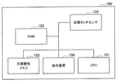
本実施形態に係る情報処理装置100は、図1に示すように、CPU101と、RAM(Random Access Memory)102と、不揮発性メモリ103と、表示装置104と、近接タッチセンサ105とを備える。
As illustrated in FIG. 1, the
CPU101は、上述したように、演算処理装置および制御装置として機能し、各種プログラムに従って情報処理装置100内の動作全般を制御する。また、CPU101は、マイクロプロセッサであってもよい。RAM102は、CPU101の実行において使用するプログラムや、その実行において適宜変化するパラメータ等を一時記憶する。これらはCPUバスなどから構成されるホストバスにより相互に接続されている。不揮発性メモリ103は、CPU101が使用するプログラムや演算パラメータ等を記憶する。不揮発性メモリ103は、例えばROM(Read Only Memory)やフラッシュメモリ等を用いることができる。
As described above, the
表示装置104は、情報を出力する出力装置の一例である。表示装置104として、例えば液晶ディスプレイ(LCD)装置、OLED(Organic Light Emitting Diode)装置などを用いることができる。近接タッチセンサ105は、ユーザが情報を入力する入力装置の一例であって、情報を入力ための入力手段と、ユーザによる入力に基づいて入力信号を生成し、CPU101に出力する入力制御回路などから構成されている。
The
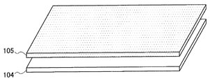
本実施形態に係る情報処理装置100において、近接タッチセンサ105は、図2に示すように、表示装置104の表示面に積層して設けられる。これにより、ユーザが表示面に指等を近づけたときに、近接タッチセンサ105によって表示面に対する指までの距離を検出することが可能となる。
In the
[GUIの出現位置制御処理の概念]
本実施形態に係る情報処理装置100は、ユーザが表示領域に指等の操作体を近接あるいは接触された位置に合わせてGUIを表示する。例えば、情報処理装置100がモバイルデバイスである場合、ユーザは、図3に示すように、長方形の表示領域200を縦長にして縦向きの状態で使用したり、表示領域200を横長にして横向きの状態で使用したりする。
[Concept of GUI Appearance Position Control Processing]
The
この際、縦向きの状態で使用するときには、装置下側から手を添えて表示領域200に表示されたオブジェクト等のGUIを操作することが考えられる。一方、横向きの状態で使用するときには、装置右側あるいは左側から手を添えて表示領域200に表示されたオブジェクトを操作することが考えられる。また、装置を斜めにして、当該装置を持ちやすい方向から手を添えて表示領域200に表示されたオブジェクトを操作することも考えられる。このように、モバイルデバイスでは様々な持ち方をすることができる。
At this time, when used in a vertically oriented state, it is conceivable to operate a GUI such as an object displayed in the
ここで、情報処理装置100は、ソフトウェアを機能させることにより、表示領域200におけるGUIの表示位置を任意に変更させることができる。そこで、本実施形態に係る情報処理装置100では、表示領域200に表示されたGUIを操作する指等の操作体の位置に応じてGUIを表示し、ユーザの操作負荷を低減し、直感的な操作を行うことができるようにする。例えば、図3に示す例では、指の近接が検出された位置(近接指検出位置)にGUIを出現させるようにする。これにより、装置を使用するときの装置の向きやGUIを操作する指の位置をユーザは気にしなくとも、操作対象のGUIが指の近接が検出された近接指検出位置に表示されるようになり、操作性を向上させることができる。
Here, the
より具体的には、例えば図4に示すように、情報処理装置100を横向きの状態で使用するときに、表示領域200に表示されるオブジェクトを操作する指が装置左側から近づいてきたとする。そして、情報処理装置100は、近接タッチセンサ105により指が表示領域200に近接したことを検出すると、近接指検出位置を特定し、表示領域200の近接指検出位置にオブジェクト210を表示させる。図4では、表示領域200の左側にオブジェクト210が表示される。
More specifically, for example, as illustrated in FIG. 4, when the
一方、情報処理装置100を縦向きの状態で使用するときに、図5に示すように、表示領域200に表示されるオブジェクトを操作する指が装置下側から近づいてきたとする。情報処理装置100は、近接タッチセンサ105により指が表示領域200に近接したことを検出すると、近接指検出位置を特定し、表示領域200の近接指検出位置にオブジェクト210を表示させる。図5では、表示領域200の下側にオブジェクト210が表示される。
On the other hand, when the
このように、操作対象のGUIが指の近接が検出された近接指検出位置に表示されるので、操作性を向上させることができる。以下では、表示領域200に近接する指の位置に応じてGUIの出現位置を制御する制御部を備える情報処理装置100と、これによるGUIの出現位置制御処理について、詳細に説明していく。
As described above, since the operation target GUI is displayed at the proximity finger detection position where the proximity of the finger is detected, the operability can be improved. Hereinafter, the
<2.情報処理装置の機能構成>
まず、図6に基づいて、本実施形態に係る情報処理装置100の機能構成について説明する。なお、図6は、本実施形態に係る情報処理装置100の機能構成を示すブロック図である。
<2. Functional configuration of information processing apparatus>
First, the functional configuration of the
本実施形態に係る情報処理装置100は、図6に示すように、入力表示部110と、位置情報取得部120と、表示制御部130と、実行処理部140と、設定記憶部150とを備える。
As illustrated in FIG. 6, the
入力表示部110は、情報を表示するとともに情報を入力するための機能部であって、検出部112と、表示部114とを備える。検出部112は、図1の近接タッチセンサ105に対応し、例えば静電式タッチパネル等を用いることができる。この場合、検出部112は、操作体と表示部114の表示面との間の近接距離に応じて変化する静電容量の値を検出する。
The
操作体が表示面に所定距離以上近接すると、検出部112により検出される静電容量が増加し、さらに近接するにつれて静電容量は増加する。そして、操作体が表示面に接触すると、検出部112により検出される静電容量が最大となる。このような検出部112に検出された静電容量の値に基づいて、後述する位置情報取得部120は、表示部114の表示面に対する操作体の位置情報を取得することができる。検出部112は、検出した静電容量の値を検出結果として位置情報取得部120へ出力する。
When the operating body is close to the display surface by a predetermined distance or more, the electrostatic capacity detected by the
表示部114は、図1の表示装置104に対応する、情報を表示する出力装置である。表示部114には、例えばGUIオブジェクトや、当該オブジェクトに関連付けられたコンテンツの内容等が表示される。また、表示部114には、表示制御部130によりオブジェクトの表示形態が変更された場合には、表示制御部130から通知されたオブジェクトの表示変更情報に基づいて、変更後のオブジェクトが表示される。
The
位置情報取得部120は、検出部112から入力された検出結果に基づいて、操作体と表示部114の表示面との位置関係を表す位置情報を取得する。上述したように、検出部112が検出した静電容量の値が大きいほど操作体と表示面とは近接しており、操作体が表示面に接触したときに静電容量の値は最大となる。静電容量の値と近接距離(あるいは近接検知領域)との対応関係は、後述する設定記憶部150に予め記憶されている。位置情報取得部120は、検出部112から入力された静電容量の値より、設定記憶部150を参照して、表示面に対して垂直方向(z方向)における指の位置を取得する。
The position
また、位置情報取得部120は、検出部112から入力された検出結果に基づいて、表示部114の表示面上における(すなわち、xy平面上における)操作体の位置を特定する。例えば、検出部112がx座標およびy座標の検出を行う静電検出用グリッドが形成された静電センサ基板により構成されているとする。このとき、検出部112は、操作体の接触に応じた各グリッドの静電容量の変化から、基板上における(すなわち、表示面における)操作体の位置を特定することができる。例えば、静電容量の最も大きい座標位置を指が表示面に最も近接している位置の座標とすることができる。あるいは、所定値以上の静電容量が検出された領域の重心位置を指が表示面に最も近接している位置の座標としてもよい。
Further, the position
このようにして、位置情報取得部120は、表示部114の表示面に対する位置情報を取得することができる。取得された操作体の位置情報は、表示制御部130および実行処理部140へ出力される。
In this way, the position
表示制御部130は、位置情報取得部120により取得された位置情報に基づいて、表示部114に表示されたオブジェクトの表示位置を制御する。表示制御部130は、図3〜図5を用いて説明したように、表示部114に表示されたオブジェクト210をユーザが操作し易いように、ユーザの指の近接位置に応じてオブジェクト210の出現位置を制御する。表示制御部130は、オブジェクト210の出現位置を決定すると、オブジェクト210の画像を生成し、表示部114へ出力する。また、表示制御部130は、指が移動されることで指の近接位置が変化すると、指の近接位置の変化に伴いオブジェクト210の表示位置を変更する。なお、表示制御部130は、後述する実行処理部140により、指の接触位置に表示するオブジェクト210の表示内容を変更する指示を受けて、表示制御を行うこともできる。
The
実行処理部140は、情報処理装置100に対する所定の操作入力に応じて、当該操作入力に関連付けられた機能を実行する。例えば、表示部114に表示されたあるオブジェクト210にユーザが指を接触させたことが検出部112により検知されたとき、実行処理部140は、位置情報取得部120から入力された位置情報に基づき、指がオブジェクト210に接触したことを認識する。そして、実行処理部140は、オブジェクト210から指が接触したオブジェクトを特定し、これに関連付けられた機能を実行する。
The
設定記憶部150は、操作体と表示面との近接距離の算出や、表示面上における操作体の位置情報の生成、その他、オブジェクトの出現位置制御処理に際して用いられる情報を設定情報として記憶する。設定記憶部150には、例えば、静電容量の値と近接距離との対応関係を記憶しており、位置情報取得部120は、かかる対応関係を参照して、検出部112から入力された静電容量の値に対応する位置を取得することができる。また、設定記憶部150には、ユーザがオブジェクト210に対して行った操作入力に対応して実行される処理内容(機能)が記憶される。設定記憶部150に記憶されている設定情報は、予め記憶されていてもよく、ユーザが設定してもよい。
The setting
なお、本実施形態に係る情報処理装置100は、オブジェクトの表示位置制御処理等において必要な情報を一時的に記憶するメモリ等を備えてもよい。
The
<3.オブジェクト出現位置制御処理>
本実施形態に係る情報処理装置100は、上記機能を備えることにより、表示面に対する指の近接位置(近接指検出位置)を検出することができる。そして、情報処理装置100は、近接指検出位置に基づいて、表示部114に表示されるオブジェクト210の出現位置を制御することで、操作性を向上させる。以下、図7〜図14に基づいて、本実施形態に係る情報処理装置100によるオブジェクト出現位置制御処理について説明する。
<3. Object appearance position control processing>
The
[オブジェクト出現位置制御:基本処理]
まず、図7および図8に基づいて、本実施形態に係る情報処理装置100によるオブジェクト出現位置制御の基本処理について説明する。なお、図7は、本実施形態に係る情報処理装置100によるオブジェクト出現位置制御処理を示すフローチャートである。図8は、本実施形態に係る情報処理装置100によるオブジェクト出現位置制御処理の一例を示す説明図である。
[Object appearance position control: basic processing]
First, basic processing of object appearance position control by the
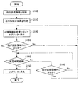
まず、情報処理装置100は、検出部112により指の位置情報を取得する(S100)。検出部112が例えば静電式タッチパネルであるときには、検出部112は、指と表示部114の表示面との間の近接距離に応じて変化する静電容量の値を検出する。そして、位置情報取得部120は、検出部112の検出結果に基づいて、表示面に対する指の近接位置を位置情報として取得する。位置情報取得部120は、表示面に対して近接する指のうち、最も表示面に近接する指の位置を特定し、近接指検出位置として表示制御部130へ出力する(S110)。最も表示面に近接する指の位置は、検出部112の検出結果より静電容量の値が最大となる位置とすることができる。
First, the
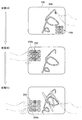
例えば、図8に示すように、情報処理装置100を横向きの状態で使用しているとする。状態(A)では指は表示面上に位置していないため、検出部112の検出値は変化しない。その後、情報処理装置100の装置左側から指が表示面に近接すると、検出部112の検出値が変化し、位置情報取得部120により近接指検出位置が特定される(状態(B))。
For example, as shown in FIG. 8, it is assumed that the
表示制御部130は、近接指検出位置の入力を受けると、近接指検出位置に応じて、表示領域200に所定のオブジェクト210を表示させる(S120)。表示制御部130は、例えば、近接指検出位置にオブジェクト210の中心が位置するようにオブジェクト210を表示させる。あるいは、表示制御部130は、オブジェクト210が指で隠れないように、第1の近接指検出位置の近傍にオブジェクト210を表示させてもよい。図8の状態(B)のように、近接指検出位置が装置左側に特定されると、状態(C)に示すように、近接指検出位置に応じて、表示領域200の左側(すなわち、装置左側)にオブジェクト210が表示される。このように、近接する指の位置に応じてオブジェクト210の出現位置が決定される。
When receiving the proximity finger detection position, the
その後、表示制御部130は、指が近接領域外に移動されたか否かを、位置情報取得部120から入力される位置情報に基づき判定する(S130)。近接領域は、表示面から所定距離だけ離隔した位置までの間の領域であり、例えば、検出部112により指の位置情報を取得可能な領域とすることができる。表示制御部130は、指が近接領域内に位置すると判定したときは、そのままオブジェクト210を表示し続ける。
Thereafter, the
一方、指が近接領域外に位置したときには、表示制御部130は、指が近接領域外に位置してからの経過時間のカウントを開始する。そして、経過時間が所定時間経過したか否かを判定し(S140)、経過時間が所定時間を経過した場合には、表示領域200に表示されていたオブジェクト210を消失させる(S150)。一方、経過時間が所定時間を経過していない場合、表示制御部130は、指が近接領域内に再び位置したか否かを判定する(S160)。そして、指が近接領域内に存在しない場合には、ステップS140の処理に戻り、指が近接領域外に位置してからの経過時間をカウントし続ける。
On the other hand, when the finger is positioned outside the proximity region, the
これに対して、指が近接領域外に位置してから、所定時間が経過する前に再び近接領域内に指が位置するようになったことが検知されると、新たに検出された近接指検出位置にオブジェクト210を表示させる(S120)。このとき、表示制御部130は、指が近接領域に位置してからの経過時間のカウントを停止し、リセットする。そして、表示制御部130は、ステップS120からの処理を繰り返す。なお、所定時間は、予め設定されてもよく、ユーザが適宜設定してもよい。
On the other hand, if it is detected that the finger is again located in the proximity area before the predetermined time has elapsed since the finger was positioned outside the proximity area, the newly detected proximity finger is detected. The
図8に示す例では、状態(D)において指が近接領域から離隔されたとする。表示制御部130は、指が近接領域外に位置した時点から経過時間のカウントを開始する。そして、所定時間内に指が再び近接領域内に位置することがなければ、表示制御部130は、状態8E)に示すように、所定時間経過後に、表示領域200に表示されていたオブジェクト210を消失させる。一方、所定時間が経過する前に、例えば状態(F)のように再び指の近接が検出された場合には、表示領域200に表示されていたオブジェクト210を新たに検出された近接指検出位置に移動させる(状態(G))。このように、指の近接位置に応じて、表示領域200に表示させるオブジェクト210の出現位置を変更することで、オブジェクト210を操作する指の位置にオブジェクト210が自動的に表示されるようになり、操作性を向上させることができる。
In the example shown in FIG. 8, it is assumed that the finger is separated from the proximity region in the state (D). The
[オブジェクト出現位置制御:近接指検出位置を2点以上検出した場合]
次に、図9および図10に基づいて、近接指検出位置を2点以上検出した場合における、情報処理装置100によるオブジェクト出現位置制御処理について説明する。この場合、情報処理装置100の検出部112は、表示面に対する複数の近接位置または接触位置を検出可能であるとする。情報処理装置100は、複数の近接指検出位置が検出された場合には、オブジェクトを操作する指が増えたと考え、オブジェクトを分割して各近接指検出位置に表示させる。これにより、複数の指でのオブジェクト操作が可能となり、操作負荷を軽減させることができる。また、複数の指での同時操作が可能となるので、操作速度の向上が期待される。
[Object appearance position control: When two or more proximity finger detection positions are detected]
Next, an object appearance position control process performed by the
なお、図9は、近接指検出位置を2点以上検出した場合における、情報処理装置100によるオブジェクト出現位置制御処理を示すフローチャートである。図10は、近接指検出位置を2点以上検出した場合における、情報処理装置100によるオブジェクト出現位置制御処理の一例を示す説明図である。以下の説明において、図7および図8に基づき説明した処理と同一の処理については詳細な説明を省略する。
FIG. 9 is a flowchart illustrating object appearance position control processing by the
本例においても、上述した基本処理と同様に、まず、情報処理装置100は、検出部112により指の位置情報を取得する(S200)。位置情報取得部120は、検出部112の検出結果に基づいて、表示面に対する指の近接位置を位置情報として取得する。そして、位置情報取得部120は、表示面に対して近接する指のうち、最も表示面に近接する指の位置を特定し、第1の近接指検出位置として表示制御部130へ出力する(S210)。
Also in this example, similarly to the basic processing described above, first, the
例えば、図10に示すように、情報処理装置100を横向きの状態で使用しているとする。状態(A)では指は表示面上に位置していないため、検出部112の検出値は変化しない。その後、情報処理装置100の装置左側から指が表示面に近接すると、検出部112の検出値が変化し、位置情報取得部120により第1の近接指検出位置が特定される(状態(B))。
For example, as shown in FIG. 10, it is assumed that the
表示制御部130は、第1の近接指検出位置の入力を受けると、第1の近接指検出位置に応じて、表示領域200に所定のオブジェクト210を表示させる(S220)。表示制御部130は、例えば、近接指検出位置にオブジェクト210の中心が位置するようにオブジェクト210を表示させる。図10の状態(B)のように、近接指検出位置が装置左側に特定されると、状態(C)に示すように、近接指検出位置に応じて、表示領域200の左側(すなわち、装置左側)にオブジェクト210が表示される。このように、近接する指の位置に応じてオブジェクト210の出現位置が決定される。
Upon receiving the input of the first proximity finger detection position, the
なお、ステップS200〜S220の処理は、図7に示すステップS100〜S120の処理と同様に行われる。 In addition, the process of step S200-S220 is performed similarly to the process of step S100-S120 shown in FIG.
その後、表示制御部130は、第1の近接指検出位置に応じて出現させたオブジェクト210が表示領域200に表示されている状態で、新たな近接指検出位置が特定されたか否かを判定する(S230)。第1の近接指検出位置にある指が近接領域外に位置した場合には、上述の図7の処理が行われるが、第1の近接指検出位置にある指が近接領域内にある状態でさらに新たな近接指検出位置が検出されたときには、オブジェクト210を操作する指が増加したと考えられる。そこで、位置情報取得部120は、位置情報から新たな近接指検出位置を特定し、第2の近接指検出位置として表示制御部130に出力する。表示制御部130は、第1の近接指検出位置に既に表示されているオブジェクト210を分割して、その一部を第2の近接指検出位置に表示させる。
Thereafter, the
例えば、図10の状態(D)に示すように、装置左側にある第1の近接指検出位置に3×3の格子状にサブオブジェクトが配列されたオブジェクト210が表示されているときに、装置右側において第2の近接指検出位置が検出されたとする。このとき、表示制御部130は、例えばオブジェクト210を構成するサブオブジェクトのうち、第2の近接指検出位置側の2列のサブオブジェクトを、第1の近接指検出位置から第2の近接指検出位置に移動させる。これにより、状態(E)のように、オブジェクト210がオブジェクト210Aとオブジェクト210Bの2つに分割されて、それぞれ第1の近接指検出位置と第2の近接指検出位置とに表示されるようになる。
For example, as shown in the state (D) of FIG. 10, when an
なお、オブジェクト210A、210Bの表示位置は、第1の近接指検出位置および第2の近接指検出位置の中心位置であってもよく、第1の近接指検出位置および第2の近接指検出位置の近傍であってもよい。
Note that the display positions of the
オブジェクト210の分割位置は、オブジェクト210に対して予め設定しておくこともでき、表示制御部130が近接指検出位置に応じて決定してもよい。例えば、2つの近接指検出位置が検出されているときに、図10の状態(D)のように近接指検出位置が装置の左右方向に並んでいるときには、状態(E)のようにオブジェクト210を左右2つに分割するようにしてもよい。あるいは、近接指検出位置が装置の上下方向に並んでいるときには、オブジェクト210を上下2つに分割するようにしてもよい。
The division position of the
図10の状態(E)のように、新たに検出された近接指検出位置に向かってオブジェクトを分割することで、ユーザはオブジェクト210が分割されてその一部が新たに検出された近接指検出位置に移動したことを直感的に認識することができる。なお、3つ以上の近接指検出位置が特定されている場合にも、オブジェクト210が表示されている位置から他の近接指検出位置へ向かってオブジェクト210を分割するようにしてもよい。
As shown in the state (E) of FIG. 10, by dividing the object toward the newly detected proximity finger detection position, the user can detect the proximity finger in which the
以上、近接指検出位置を2点以上検出した場合における、情報処理装置100によるオブジェクト出現位置制御処理について説明した。このように、複数の近接指検出位置が検出されたとき、既に表示領域200に表示されているオブジェクト210を分割して、新たに検出された近接指検出位置に分割されたオブジェクト210の一部を表示させるようにする。これにより、片手で操作入力を行う場合等のように1本の指で操作をするには操作負荷が高い場合でも、操作対象のオブジェクトを複数の指に分散させることで、操作負荷を軽減することができる。また、複数の指での同時操作が可能となるので、操作速度の向上が期待される。
The object appearance position control process by the
なお、既に表示されているオブジェクト210を他の指で明示的にドラッグアンドドロップ操作することで、他の指への対応関係を構築するようにしてもよい。これにより、ドラッグアンドドロップ操作されたオブジェクト210を他の指の近傍に移動させ、追従させる操作も可能とすることができる。
Note that a correspondence relationship with another finger may be constructed by explicitly dragging and dropping the already displayed
[オブジェクトに対する接触位置に応じた関連オブジェクトの表示]
近接指検出位置を2点以上検出した場合、図9および図10では既に表示されているオブジェクトを分割して、新たに検出された近接指検出位置に表示させる例を説明した。近接指検出位置を2点以上検出した場合の他の表示制御例として、例えば、表示領域200に表示されているオブジェクト210に対する接触位置に応じて、新たに検出された近接指検出位置に表示されるオブジェクトの内容を変化させることもできる。図11に、オブジェクト210に対する指の接触位置に応じた関連オブジェクトを表示する処理の一例を示す。
[Display related objects according to the contact position of the object]
In the case where two or more proximity finger detection positions are detected, the example in which the already displayed object is divided and displayed at the newly detected proximity finger detection position in FIGS. 9 and 10 has been described. As another display control example when two or more proximity finger detection positions are detected, for example, the display is displayed at the newly detected proximity finger detection position according to the contact position with respect to the
図11の状態(A)は、図9のステップS220までの処理が行われ、第1の近接指検出位置にオブジェクト210が表示された状態である。ここで、オブジェクト210を構成するサブオブジェクトには、それぞれ関連オブジェクトが関連付けられている。関連オブジェクトは、対応するサブオブジェクトに指が接触された状態で、新たな近接指検出位置が検出されたとき、新たな近接指検出位置に表示される。
The state (A) in FIG. 11 is a state in which the processing up to step S220 in FIG. 9 is performed and the
例えば、図11の状態(B)に示すように、第1の近接指検出位置に表示されたオブジェクト210のサブオブジェクト210aに対する指の接触が検出されると、表示制御部130は、新たな近接指検出位置の検出を行う。そして、新たな近接指検出位置を検出すると、表示制御部130は、その位置にサブオブジェクト210aに関連付けられた関連オブジェクト220aを表示する。また、図11の状態(C)に示すように、第1の近接指検出位置に表示されたオブジェクト210のサブオブジェクト210bに対する指の接触が検出されると、表示制御部130は、新たな近接指検出位置の検出を行う。そして、新たな近接指検出位置を検出すると、表示制御部130は、その位置にサブオブジェクト210bに関連付けられた関連オブジェクト220bを表示する。
For example, as shown in the state (B) of FIG. 11, when the finger contact with the sub-object 210a of the
このように、指が接触されているサブオブジェクトに関連付けられた関連オブジェクトを、第1の近接指検出位置の次に検出された新たな近接指検出位置に表示させることで、新たな近接指検出位置にある指で関連オブジェクトを操作することが可能となる。これにより、片手で操作入力を行う場合等のように1本の指で操作をするには操作負荷が高い場合でも、操作対象のオブジェクトを複数の指に分散させることで、操作負荷を軽減することができる。また、複数の指での操作が可能となるので、操作速度の向上が期待される。 In this way, by displaying the related object associated with the sub-object with which the finger is in contact at the new proximity finger detection position detected next to the first proximity finger detection position, a new proximity finger detection is performed. It is possible to operate the related object with the finger at the position. Thus, even when the operation load is high for operation with one finger, such as when performing an operation input with one hand, the operation load is reduced by distributing the operation target object to a plurality of fingers. be able to. In addition, since operation with a plurality of fingers is possible, an improvement in operation speed is expected.
[複数オブジェクトの分離表示]
近接指検出位置を2点以上検出した場合のさらに他の表示制御例として、例えば、表示領域200に表示されている複数のオブジェクトを、複数の近接指検出位置に分離して表示させることもできる。図12に、複数のオブジェクトを複数の近接指検出位置に分離して表示する処理の一例を示す。
[Separate display of multiple objects]
As still another display control example when two or more proximity finger detection positions are detected, for example, a plurality of objects displayed in the
図12に示す例では、表示領域200に、文字入力のためのキーボードオブジェクト(以下、「キーボード」とする。)230と、キーボード230から入力された入力文字列より予測される予測文字列が表示される入力サジェストオブジェクト(以下、「サジェスト」とする。)240とが表示されている。キーボード230から文字が入力されると、情報処理装置100は、入力文字列から、辞書データベースや過去に入力した文字列の履歴等を参照して、予測文字列をサジェスト240に表示させる。ユーザはサジェスト240に表示された予測文字列に指を接触させることで、その予測文字列を入力することができるので、操作負荷を軽減することができる。
In the example illustrated in FIG. 12, a keyboard object (hereinafter referred to as “keyboard”) 230 for character input and a predicted character string predicted from an input character string input from the
ここで、キーボード230とサジェスト240とは、図12の状態(A)に示すように、最初に検出された近接指検出位置に合わせて表示される。このとき、ユーザは、最初に検出された近接指検出位置にある指でキーボード230による文字入力と、サジェスト240からの予測文字列選択との2つの入力を行うことになる。そこで、次に近接指検出位置が検出されたとき、表示制御部130は、キーボード230およびサジェスト240のいずれか一方を、新たな近接指検出位置に移動させる。例えば、図12の状態(B)に示すように、装置左側に新たな近接指検出位置が検出されると、表示制御部130は、状態(C)に示すように、サジェスト240を新たな近接指検出位置に移動させる。
Here, the
これにより、一方の指ではキーボード230による文字入力を行い、他方の指ではサジェスト240に表示された予測文字列の選択を行うことができるようになる。このように、両手での操作が可能となり、操作負荷の軽減、同時操作による操作速度の向上が可能となる。
As a result, it is possible to input characters using the
なお、図12の状態(A)において、1つの指でも操作入力をし易くするため、図13に示すように、指の移動に応じてオブジェクトの表示位置を変更させてもよい。例えば、図13上図に示すように、近接指検出位置にある指がキーボード230上にある状態から、サジェスト240に表示されている予測文字列の選択を行うために指を上方向に移動させたとする。このとき、表示制御部130は、キーボード230およびサジェスト240を、指が上方向に移動するのに伴って下方向に移動させる。これにより、操作対象となるサジェスト240が指に近づき、選択操作を容易に行うことができるようになる。
In the state (A) in FIG. 12, the display position of the object may be changed according to the movement of the finger as shown in FIG. For example, as shown in the upper diagram of FIG. 13, when the finger at the proximity finger detection position is on the
[ドローイングアプリケーションへの適用]
近接指検出位置を2点以上検出した場合のさらに他の表示制御例として、例えば、表示面に接触された指を動かして描画できるように情報処理装置100を機能させるドローイングアプリケーションへの適用が考えられる。図14に、近接指検出位置を2点以上検出した場合における、情報処理装置によるオブジェクト出現位置制御処理をドローイングアプリケーションに適用した例を示す。
[Apply to drawing application]
As another display control example in the case where two or more proximity finger detection positions are detected, for example, application to a drawing application that causes the
例えば、図14の状態(A)のように、描画する線の色を選択するパレットオブジェクト(以下、「パレット」とする。)250から所望の色を選択し、指を表示面に接触させて動かし、描画する動作が行われているとする。かかる状態において、新たな近接指検出位置が検出されると、図14の状態(B)に示すように、表示領域200の右下に表示されていたパレット250が、新たな近接指検出位置のある表示領域200の左上に移動し表示されるようになる。これにより、新たな近接指検出位置にある指によって、パレット250を操作することが可能となる。このとき、例えば、選択されている色のオブジェクト250aを他の色のオブジェクトよりも大きく表示させてもよい。
For example, as shown in state (A) of FIG. 14, a desired color is selected from a palette object (hereinafter referred to as “palette”) 250 for selecting the color of a line to be drawn, and a finger is brought into contact with the display surface. It is assumed that an operation of moving and drawing is performed. In this state, when a new proximity finger detection position is detected, as shown in the state (B) of FIG. 14, the
その後、新たな近接指検出位置にある指によってパレット250を操作し、他の色のオブジェクト250bに指が接触されると、状態(C)に示すように、描画する線の色がオブジェクト250bに対応する色に変更される。このように、操作の属性切り換えを迅速に行うことができる。
After that, when the
なお、本例では、線の描画に関連する色の選択操作を、新たに検出された近接指検出位置の指で行うことができるようにしたが、本発明はかかる例に限定されない。現在実行されている機能に関連する操作を行うためのオブジェクトを、新たに検出された近接指検出位置に表示させることで、操作を迅速に行うことができるようになり、操作性を向上焦ることができる。 In this example, the color selection operation related to line drawing can be performed with the newly detected finger at the proximity finger detection position, but the present invention is not limited to this example. By displaying an object for performing an operation related to the currently executed function at the newly detected proximity finger detection position, the operation can be performed quickly, and the operability is improved. Can do.
[近接指によるトラッキング]
上述したように、本実施形態に係る情報処理装置100では、近接指検出位置にオブジェクトを出現させることで、ユーザがオブジェクトの表示位置に指を移動させて出現させる必要がなく、操作負荷を低減することができる。ここで、既に表示されているオブジェクト210の表示領域(オブジェクト表示領域)から当該オブジェクト210を出現させた指が離れると、せっかく指の近傍に表示させたオブジェクト210を操作し難くなってしまう。そこで、本実施形態に係る情報処理装置100は、オブジェクト210を出現させた指がオブジェクト表示領域から所定距離以上離れると、オブジェクト210を指に追従して移動させる。
[Tracking by proximity finger]
As described above, in the
図15に、オブジェクト210を出現させた指の移動に応じてオブジェクト210を移動させたときの、オブジェクト210の表示位置の変化を示す。図15の状態(A)に示すように、位置情報取得部120により特定された近接指検出位置に、オブジェクト210が出現されたとする。このとき、情報処理装置100の装置左上側に近接指検出位置があるので、オブジェクト210は装置左上に表示される。
FIG. 15 shows a change in the display position of the
次いで、オブジェクト210を出現させた指が、指を表示面に近接させた状態で装置左下へ移動されたとする。このとき、表示制御部130は、位置情報取得部120から入力される位置情報から当該指の移動を検知すると、図15の状態(C)のように指を追ってオブジェクト210を装置左下へ移動させる。
Next, it is assumed that the finger on which the
このとき、表示制御部130は、移動する指の速度が所定速度以下で移動している場合にのみ、オブジェクト210を指に追従して移動させるようにしてもよい。指の速度が所定速度より大きい場合には、例えば移動方向にあるオブジェクトを操作する等ユーザが意図的に指を移動させている可能性が高いため、第1の近接指検出位置に表示されたオブジェクト210は移動させないようにする。これにより、ユーザが意図しないオブジェクト210の移動が生じるのを防止することができる。
At this time, the
なお、指の速度が所定速度より大きい場合には、表示制御部130は、当該指により出現されたオブジェクト210の操作は行われないものと判断し、オブジェクト210を表示領域200から消失させてもよい。また、近接領域から指が離隔されて所定時間以上経過した場合にも、オブジェクト210を表示領域200から消失させるようにしてもよい。
If the speed of the finger is greater than the predetermined speed, the
状態(C)から情報処理装置100の持ち方が状態(D)のように変更されても、オブジェクト210は、当該オブジェクト210を表示させた指の移動に応じて表示位置が移動され、その指での操作が可能な状態にされる。そして、指が装置左下側から装置右下側へ移動されると、表示制御部130は、図15の状態(E)のように指を追ってオブジェクト210を装置右下側へ移動させる。
Even when the holding state of the
このように、オブジェクト210を出現させた指の動きに追従して、オブジェクト210の表示位置が変更される。これにより、情報処理装置100を持ち変えたり、持ち方を変更したりしても、近接指検出位置に応じてオブジェクト210が移動され、オブジェクト210の操作を常に行いやすくすることができる。なお、指に追従して移動されたオブジェクト210の表示位置は、例えば、指の近接指検出位置にオブジェクト210の中心位置(図15の例では、サブオブジェクト210a)が位置するように決定してもよい。あるいは、オブジェクト210を移動させるターゲット位置を指の移動領域に応じてある程度離散化して規定しておき、近接指検出位置に最も近いターゲット位置にオブジェクト210を表示させるようにしてもよい。
Thus, the display position of the
また、表示領域200において指が移動されてもオブジェクト210の追従移動を行わない、不感帯領域を設けることもできる。例えば、表示領域200にオブジェクト210以外の情報が表示されているとき、当該情報が表示されている領域に指を移動させると、かかる情報の上にオブジェクト210が表示されてしまい、他の情報の視認を妨げることになる。このように、オブジェクト210を表示させたくない領域を不感帯領域として設定することで、オブジェクト210の移動可能領域を制限することができる。
In addition, it is possible to provide a dead zone area in which the
さらに、表示領域200に表示されたオブジェクト210に対して明示的にドラッグアンドドロップ操作を行うことにより、明示的にオブジェクト210の移動を行うことも可能である。
Further, the
以上、本実施形態に係る情報処理装置100とこれによる表示制御処理について説明した。本実施形態によれば、指が表示面に対して近接したときに、近接指検出位置にGUIが表示されるので、ユーザは指を表示面に接触させる前にGUIの挙動を認識することができる。これにより、これから起こり得る現象や可能な操作を想起することができ、快適・安心に操作を行うことができる。また、近接指検出位置に応じて操作するGUIが表示されるので、ユーザの操作負荷を軽減することができる。そして、GUIを出現させた指が移動しても、その指に対応付けられたGUIを追従して移動させることもでき、さらにユーザの操作負荷を軽減することができる。
Heretofore, the
また、本実施形態によれば、複数の近接指検出位置が検出可能となることで、既に表示されているGUIを分割したり、追加操作可能としたり、実行されている機能の補助操作を可能としたりすることもできる。これにより、操作負荷の軽減とともに、複数の指による同時操作も可能となり、操作速度を向上させることもできる。 In addition, according to the present embodiment, since it is possible to detect a plurality of proximity finger detection positions, it is possible to divide a GUI that has already been displayed, to enable additional operations, and to perform auxiliary operations of functions that are being executed It can also be done. As a result, the operation load can be reduced, simultaneous operation with a plurality of fingers can be performed, and the operation speed can be improved.
以上、添付図面を参照しながら本発明の好適な実施形態について詳細に説明したが、本発明はかかる例に限定されない。本発明の属する技術の分野における通常の知識を有する者であれば、特許請求の範囲に記載された技術的思想の範疇内において、各種の変更例または修正例に想到し得ることは明らかであり、これらについても、当然に本発明の技術的範囲に属するものと了解される。 The preferred embodiments of the present invention have been described in detail above with reference to the accompanying drawings, but the present invention is not limited to such examples. It is obvious that a person having ordinary knowledge in the technical field to which the present invention pertains can come up with various changes or modifications within the scope of the technical idea described in the claims. Of course, it is understood that these also belong to the technical scope of the present invention.
100 情報処理装置
112 検出部
114 表示部
120 位置情報取得部
130 表示制御部
140 実行制御部
150 設定記憶部
200 表示領域
DESCRIPTION OF
Claims (7)
前記操作体が、前記表示面と当該表示面から所定距離離隔した位置との間の近接領域に位置したとき、前記位置情報に基づいて、前記表示部の前記操作体に対応する位置にオブジェクトを表示する表示制御部と、
を備え、
前記表示制御部は、前記操作体が前記近接領域内から前記近接領域外へ移動した後、所定時間経過する前に、再び前記近接領域内に位置したとき、再び前記近接領域内に位置したときの前記操作体の位置情報に基づいて、前記表示部の前記操作体に対応する位置に前記オブジェクトを表示し、
前記位置情報取得部は、複数の操作体の位置情報を取得可能であり、
前記表示制御部は、
最初に前記近接領域に位置した第1の操作体の位置情報に基づいて、前記表示部の前記第1の操作体に対応する位置にオブジェクトを表示し、
前記オブジェクトが表示された状態で、第2の操作体が前記近接領域に位置したとき、前記第2の操作体の位置情報に基づいて、前記表示部に表示された前記オブジェクトの一部を、前記表示部の前記第2の操作体に対応する位置に表示する、情報処理装置。 A position information acquisition unit that acquires position information of the operating tool with respect to the display surface of the display unit on which the object is displayed;
When the operation body is located in a proximity region between the display surface and a position separated from the display surface by a predetermined distance, an object is placed at a position corresponding to the operation body of the display unit based on the position information. A display control unit for displaying;
With
The display control unit, when the operating body moves from the proximity area to the outside of the proximity area, and when it is located in the proximity area again before a predetermined time elapses, when it is located in the proximity area again. Based on the position information of the operation body, the object is displayed at a position corresponding to the operation body of the display unit ,
The position information acquisition unit can acquire position information of a plurality of operating bodies,
The display control unit
Based on the position information of the first operating body first positioned in the proximity region, an object is displayed at a position corresponding to the first operating body of the display unit,
When the second operating body is positioned in the proximity area in a state where the object is displayed, based on the positional information of the second operating body, a part of the object displayed on the display unit is An information processing apparatus that displays at a position corresponding to the second operating body of the display unit.
前記表示制御部は、
最初に前記近接領域に位置した第1の操作体の位置情報に基づいて、前記表示部の前記第1の操作体に対応する位置にオブジェクトを表示し、
前記オブジェクトを構成するサブオブジェクトのうち1つの前記サブオブジェクトに前記第1の操作体が接触された状態で、第2の操作体が前記近接領域に位置したとき、前記第1の操作体が接触している前記サブオブジェクトに関連付けられた関連オブジェクトを、前記表示部の前記第2の操作体に対応する位置に表示する、請求項1に記載の情報処理装置。 The position information acquisition unit can acquire position information of a plurality of operating bodies,
The display control unit
Based on the position information of the first operating body first positioned in the proximity region, an object is displayed at a position corresponding to the first operating body of the display unit,
When the first operating body is in contact with one of the sub-objects constituting the object and the second operating body is positioned in the proximity region, the first operating body is in contact The information processing apparatus according to claim 1, wherein a related object associated with the sub-object being displayed is displayed at a position corresponding to the second operation body of the display unit.
前記表示制御部は、
最初に前記近接領域に位置した第1の操作体の位置情報に基づいて、前記表示部の前記第1の操作体に対応する位置に複数のオブジェクトを表示し、
前記複数のオブジェクトが表示された状態で、第2の操作体が前記近接領域に位置したとき、前記表示部に表示された前記複数のオブジェクトのうち少なくとも1つを、前記表示部の前記第2の操作体に対応する位置に表示する、請求項1に記載の情報処理装置。 The position information acquisition unit can acquire position information of a plurality of operating bodies,
The display control unit
First, based on position information of the first operating body located in the proximity region, a plurality of objects are displayed at positions corresponding to the first operating body of the display unit,
In a state where the plurality of objects are displayed, when the second operating body is positioned in the proximity region, at least one of the plurality of objects displayed on the display unit is selected from the second unit of the display unit. The information processing apparatus according to claim 1, wherein the information processing apparatus is displayed at a position corresponding to the operating body.
前記操作体が、前記表示面と当該表示面から所定距離離隔した位置との間の近接領域に位置したとき、前記位置情報に基づいて、表示制御部により前記表示部の前記操作体に対応する位置にオブジェクトを表示するステップと、
を含み、
前記操作体が前記近接領域内から前記近接領域外へ移動した後、所定時間経過する前に、再び前記近接領域内に位置したとき、再び前記近接領域内に位置したときの前記操作体の位置情報に基づいて、前記表示部の前記操作体に対応する位置に前記オブジェクトを表示し、
前記位置情報取得部は、複数の操作体の位置情報を取得可能であり、
最初に前記近接領域に位置した第1の操作体の位置情報に基づいて、前記表示部の前記第1の操作体に対応する位置にオブジェクトを表示し、
前記オブジェクトが表示された状態で、第2の操作体が前記近接領域に位置したとき、前記第2の操作体の位置情報に基づいて、前記表示部に表示された前記オブジェクトの一部を、前記表示部の前記第2の操作体に対応する位置に表示する、情報処理方法。 Acquiring the position information of the operating tool relative to the display surface of the display unit on which the object is displayed by the position information acquisition unit;
When the operation body is located in a proximity region between the display surface and a position separated from the display surface by a predetermined distance, the display control unit corresponds to the operation body of the display unit based on the position information. Displaying an object at a position;
Including
The position of the operating body when it is located in the proximity area again when it is located in the proximity area again after a predetermined time has elapsed after the operating body has moved from inside the proximity area to outside the proximity area. Based on the information, the object is displayed at a position corresponding to the operation body of the display unit ,
The position information acquisition unit can acquire position information of a plurality of operating bodies,
Based on the position information of the first operating body first positioned in the proximity region, an object is displayed at a position corresponding to the first operating body of the display unit,
When the second operating body is positioned in the proximity area in a state where the object is displayed, based on the positional information of the second operating body, a part of the object displayed on the display unit is An information processing method for displaying at a position corresponding to the second operating body of the display unit .
オブジェクトが表示される表示部の表示面に対する操作体の位置情報を取得する位置情報取得部と、
前記操作体が、前記表示面と当該表示面から所定距離離隔した位置との間の近接領域に位置したとき、前記位置情報に基づいて、前記表示部の前記操作体に対応する位置にオブジェクトを表示する表示制御部と、
を備え、
前記表示制御部は、前記操作体が前記近接領域内から前記近接領域外へ移動した後、所定時間経過する前に、再び前記近接領域内に位置したとき、再び前記近接領域内に位置したときの前記操作体の位置情報に基づいて、前記表示部の前記操作体に対応する位置に前記オブジェクトを表示し、
前記位置情報取得部は、複数の操作体の位置情報を取得可能であり、
最初に前記近接領域に位置した第1の操作体の位置情報に基づいて、前記表示部の前記第1の操作体に対応する位置にオブジェクトを表示し、
前記オブジェクトが表示された状態で、第2の操作体が前記近接領域に位置したとき、前記第2の操作体の位置情報に基づいて、前記表示部に表示された前記オブジェクトの一部を、前記表示部の前記第2の操作体に対応する位置に表示する、情報処理装置として機能させるためのコンピュータプログラム。 Computer
A position information acquisition unit that acquires position information of the operating tool with respect to the display surface of the display unit on which the object is displayed;
When the operation body is located in a proximity region between the display surface and a position separated from the display surface by a predetermined distance, an object is placed at a position corresponding to the operation body of the display unit based on the position information. A display control unit for displaying;
With
The display control unit, when the operating body moves from the proximity area to the outside of the proximity area, and when it is located in the proximity area again before a predetermined time elapses, when it is located in the proximity area again. Based on the position information of the operation body, the object is displayed at a position corresponding to the operation body of the display unit ,
The position information acquisition unit can acquire position information of a plurality of operating bodies,
Based on the position information of the first operating body first positioned in the proximity region, an object is displayed at a position corresponding to the first operating body of the display unit,
When the second operating body is positioned in the proximity area in a state where the object is displayed, based on the positional information of the second operating body, a part of the object displayed on the display unit is The computer program for functioning as an information processing apparatus displayed on the said display part in the position corresponding to the said 2nd operation body .
Priority Applications (4)
| Application Number | Priority Date | Filing Date | Title |
|---|---|---|---|
| JP2010199637A JP5630160B2 (en) | 2010-09-07 | 2010-09-07 | Information processing apparatus, information processing method, and computer program |
| EP11175331.5A EP2426585A3 (en) | 2010-09-07 | 2011-07-26 | Information processing apparatus, information processing method, and computer program. |
| US13/212,531 US20120056829A1 (en) | 2010-09-07 | 2011-08-18 | Information Processing Apparatus, Information Processing Method, and Computer Program |
| CN201110259924.XA CN102402384B (en) | 2010-09-07 | 2011-08-31 | Information processing apparatus, and information processing method |
Applications Claiming Priority (1)
| Application Number | Priority Date | Filing Date | Title |
|---|---|---|---|
| JP2010199637A JP5630160B2 (en) | 2010-09-07 | 2010-09-07 | Information processing apparatus, information processing method, and computer program |
Publications (2)
| Publication Number | Publication Date |
|---|---|
| JP2012058881A JP2012058881A (en) | 2012-03-22 |
| JP5630160B2 true JP5630160B2 (en) | 2014-11-26 |
Family
ID=45002170
Family Applications (1)
| Application Number | Title | Priority Date | Filing Date |
|---|---|---|---|
| JP2010199637A Expired - Fee Related JP5630160B2 (en) | 2010-09-07 | 2010-09-07 | Information processing apparatus, information processing method, and computer program |
Country Status (4)
| Country | Link |
|---|---|
| US (1) | US20120056829A1 (en) |
| EP (1) | EP2426585A3 (en) |
| JP (1) | JP5630160B2 (en) |
| CN (1) | CN102402384B (en) |
Families Citing this family (16)
| Publication number | Priority date | Publication date | Assignee | Title |
|---|---|---|---|---|
| CN103376972A (en) * | 2012-04-12 | 2013-10-30 | 环达电脑(上海)有限公司 | Electronic device and control method of touch control screen of electronic device |
| JP5679606B2 (en) * | 2012-04-17 | 2015-03-04 | パナソニック インテレクチュアル プロパティ コーポレーション オブアメリカPanasonic Intellectual Property Corporation of America | Portable electronic devices |
| WO2013183722A1 (en) * | 2012-06-08 | 2013-12-12 | Necカシオモバイルコミュニケーションズ株式会社 | Electronic device and controlling method and program therefor |
| US9152319B2 (en) * | 2012-07-16 | 2015-10-06 | Avaya Inc. | Method for simplifying a Swype based touch-screen keypad for fast text entry |
| JP5798532B2 (en) * | 2012-08-23 | 2015-10-21 | 株式会社Nttドコモ | User interface device, user interface method and program |
| JP2014081732A (en) * | 2012-10-15 | 2014-05-08 | Ntt Docomo Inc | Portable electronic device and display method |
| JP6063734B2 (en) * | 2012-12-25 | 2017-01-18 | 京セラ株式会社 | Mobile terminal device, unlocking method and program |
| GB2510333A (en) | 2013-01-30 | 2014-08-06 | Ibm | Emulating pressure sensitivity on multi-touch devices |
| US9035951B2 (en) * | 2013-06-20 | 2015-05-19 | Appsense Limited | Systems and methods for drawing shapes with minimal user interaction |
| WO2015035580A1 (en) * | 2013-09-11 | 2015-03-19 | 东莞宇龙通信科技有限公司 | Display method for touchscreen and terminal |
| US10025489B2 (en) | 2013-09-16 | 2018-07-17 | Microsoft Technology Licensing, Llc | Detecting primary hover point for multi-hover point device |
| DE102014208222A1 (en) * | 2014-04-30 | 2015-11-05 | Siemens Aktiengesellschaft | A method of retrieving application commands, arithmetic unit, and medical imaging system |
| KR20150126494A (en) * | 2014-05-02 | 2015-11-12 | 엘지전자 주식회사 | Mobile terminal and method for controlling the same |
| JP2016004541A (en) * | 2014-06-19 | 2016-01-12 | 本田技研工業株式会社 | Vehicular operation input apparatus |
| US10229657B2 (en) * | 2015-06-17 | 2019-03-12 | International Business Machines Corporation | Fingerprint directed screen orientation |
| KR102560598B1 (en) | 2016-12-21 | 2023-07-28 | 삼성전자주식회사 | Display Apparatus AND CONTROLLING METHOD THEREOF |
Family Cites Families (30)
| Publication number | Priority date | Publication date | Assignee | Title |
|---|---|---|---|---|
| JPH09146708A (en) * | 1995-11-09 | 1997-06-06 | Internatl Business Mach Corp <Ibm> | Driving method for touch panel and touch input method |
| US9292111B2 (en) * | 1998-01-26 | 2016-03-22 | Apple Inc. | Gesturing with a multipoint sensing device |
| JP2002358162A (en) * | 2001-06-01 | 2002-12-13 | Sony Corp | Picture display device |
| CN1280700C (en) * | 2002-07-04 | 2006-10-18 | 皇家飞利浦电子股份有限公司 | Automatically adaptable virtual keyboard |
| US7106312B2 (en) * | 2003-11-10 | 2006-09-12 | Microsoft Corporation | Text input window with auto-growth |
| US8381135B2 (en) * | 2004-07-30 | 2013-02-19 | Apple Inc. | Proximity detector in handheld device |
| US7728825B2 (en) * | 2005-03-22 | 2010-06-01 | Microsoft Corporation | Targeting in a stylus-based user interface |
| US7586481B1 (en) * | 2005-05-10 | 2009-09-08 | Apple Inc. | Display-pointer visibility |
| US10521022B2 (en) * | 2006-03-17 | 2019-12-31 | Conversant Wireless Licensing S.a.r.l. | Mobile communication terminal and method therefor |
| US8077153B2 (en) * | 2006-04-19 | 2011-12-13 | Microsoft Corporation | Precise selection techniques for multi-touch screens |
| JP4841359B2 (en) * | 2006-08-21 | 2011-12-21 | アルパイン株式会社 | Display control device |
| US7890863B2 (en) | 2006-10-04 | 2011-02-15 | Immersion Corporation | Haptic effects with proximity sensing |
| US7877707B2 (en) * | 2007-01-06 | 2011-01-25 | Apple Inc. | Detecting and interpreting real-world and security gestures on touch and hover sensitive devices |
| US7986840B2 (en) * | 2007-04-13 | 2011-07-26 | Apple Inc. | Tracking workflow in manipulating media items |
| US20090012959A1 (en) * | 2007-07-06 | 2009-01-08 | Nokia Corporation | Method, Apparatus and Computer Program Product for Providing Presentation of a Media Collection |
| US8947364B2 (en) * | 2007-08-20 | 2015-02-03 | Synaptics Incorporated | Proximity sensor device and method with activation confirmation |
| JP2009116769A (en) * | 2007-11-09 | 2009-05-28 | Sony Corp | Input device, control method for input device and program |
| CA2714534C (en) * | 2008-02-28 | 2018-03-20 | Kenneth Perlin | Method and apparatus for providing input to a processor, and a sensor pad |
| KR101456490B1 (en) * | 2008-03-24 | 2014-11-03 | 삼성전자주식회사 | Touch screen keyboard display method and apparatus thereof |
| KR101513023B1 (en) * | 2008-03-25 | 2015-04-22 | 엘지전자 주식회사 | Terminal and method of displaying information therein |
| GB2462579A (en) * | 2008-06-10 | 2010-02-17 | Sony Service Ct | Touch screen display including proximity sensor |
| JP4609543B2 (en) * | 2008-07-25 | 2011-01-12 | ソニー株式会社 | Information processing apparatus and information processing method |
| JP4609557B2 (en) * | 2008-08-29 | 2011-01-12 | ソニー株式会社 | Information processing apparatus and information processing method |
| KR20100041006A (en) * | 2008-10-13 | 2010-04-22 | 엘지전자 주식회사 | A user interface controlling method using three dimension multi-touch |
| US8963849B2 (en) * | 2008-12-04 | 2015-02-24 | Mitsubishi Electric Corporation | Display input device |
| CN102150114B (en) * | 2009-02-06 | 2014-01-22 | 松下电器产业株式会社 | Image display device |
| JP2010199637A (en) | 2009-02-20 | 2010-09-09 | Nec Corp | Portable terminal, data sharing system, data updating method and program |
| US9141284B2 (en) * | 2009-05-28 | 2015-09-22 | Microsoft Technology Licensing, Llc | Virtual input devices created by touch input |
| US8373669B2 (en) * | 2009-07-21 | 2013-02-12 | Cisco Technology, Inc. | Gradual proximity touch screen |
| JP5477203B2 (en) * | 2010-07-01 | 2014-04-23 | 株式会社ニコン | Input device |
-
2010
- 2010-09-07 JP JP2010199637A patent/JP5630160B2/en not_active Expired - Fee Related
-
2011
- 2011-07-26 EP EP11175331.5A patent/EP2426585A3/en not_active Ceased
- 2011-08-18 US US13/212,531 patent/US20120056829A1/en not_active Abandoned
- 2011-08-31 CN CN201110259924.XA patent/CN102402384B/en not_active Expired - Fee Related
Also Published As
| Publication number | Publication date |
|---|---|
| CN102402384A (en) | 2012-04-04 |
| CN102402384B (en) | 2017-04-12 |
| JP2012058881A (en) | 2012-03-22 |
| EP2426585A2 (en) | 2012-03-07 |
| EP2426585A3 (en) | 2016-01-13 |
| US20120056829A1 (en) | 2012-03-08 |
Similar Documents
| Publication | Publication Date | Title |
|---|---|---|
| JP5630160B2 (en) | Information processing apparatus, information processing method, and computer program | |
| JP5732784B2 (en) | Information processing apparatus, information processing method, and computer program | |
| US8553002B2 (en) | Information processing apparatus, information processing method, and computer program | |
| JP5350437B2 (en) | Touch sensor system | |
| JP2018049657A (en) | Classifying intent of user inputs | |
| US20160210008A1 (en) | Electronic device, method for controlling electronic device, and storage medium | |
| US9335844B2 (en) | Combined touchpad and keypad using force input | |
| US20110169760A1 (en) | Device for control of electronic apparatus by manipulation of graphical objects on a multicontact touch screen | |
| US9792013B2 (en) | Interface scanning for disabled users | |
| KR20150068330A (en) | A Device for operating according to pressure state of touch input and method thereof | |
| US20110283212A1 (en) | User Interface | |
| US10613723B2 (en) | Information processing apparatus, information processing method, and computer program product | |
| KR20110109551A (en) | Touch screen device and method for processing input of the same | |
| JP2011248888A (en) | Method and dual screen device for user gesture on dual screen | |
| JP2011014044A (en) | Apparatus and method for controlling operation and computer program | |
| JP6022807B2 (en) | Information processing program, information processing apparatus, information processing system, and information processing control method | |
| JP2012037978A (en) | Information processing device, information processing method, and program | |
| KR102205283B1 (en) | Electro device executing at least one application and method for controlling thereof | |
| JP2008065504A (en) | Touch panel control device and touch panel control method | |
| KR101771259B1 (en) | Apparatus for inputting a character on a touch screen and method for inputting a character thereof | |
| JP2011134273A (en) | Information processor, information processing method, and program | |
| US9632697B2 (en) | Information processing apparatus and control method thereof, and non-transitory computer-readable medium | |
| JP2015153197A (en) | Pointing position deciding system | |
| KR20140006893A (en) | Electronic apparatus, display method, and program | |
| US11893229B2 (en) | Portable electronic device and one-hand touch operation method thereof |
Legal Events
| Date | Code | Title | Description |
|---|---|---|---|
| A621 | Written request for application examination |
Free format text: JAPANESE INTERMEDIATE CODE: A621 Effective date: 20130807 |
|
| A977 | Report on retrieval |
Free format text: JAPANESE INTERMEDIATE CODE: A971007 Effective date: 20140221 |
|
| A131 | Notification of reasons for refusal |
Free format text: JAPANESE INTERMEDIATE CODE: A131 Effective date: 20140225 |
|
| A521 | Request for written amendment filed |
Free format text: JAPANESE INTERMEDIATE CODE: A523 Effective date: 20140423 |
|
| A02 | Decision of refusal |
Free format text: JAPANESE INTERMEDIATE CODE: A02 Effective date: 20140617 |
|
| A521 | Request for written amendment filed |
Free format text: JAPANESE INTERMEDIATE CODE: A523 Effective date: 20140813 |
|
| A911 | Transfer to examiner for re-examination before appeal (zenchi) |
Free format text: JAPANESE INTERMEDIATE CODE: A911 Effective date: 20140825 |
|
| TRDD | Decision of grant or rejection written | ||
| A01 | Written decision to grant a patent or to grant a registration (utility model) |
Free format text: JAPANESE INTERMEDIATE CODE: A01 Effective date: 20140909 |
|
| A61 | First payment of annual fees (during grant procedure) |
Free format text: JAPANESE INTERMEDIATE CODE: A61 Effective date: 20140922 |
|
| R250 | Receipt of annual fees |
Free format text: JAPANESE INTERMEDIATE CODE: R250 |
|
| LAPS | Cancellation because of no payment of annual fees |