EP2860602B1 - System and method for reducing the stopping distance of an aircraft - Google Patents
System and method for reducing the stopping distance of an aircraft Download PDFInfo
- Publication number
- EP2860602B1 EP2860602B1 EP14185988.4A EP14185988A EP2860602B1 EP 2860602 B1 EP2860602 B1 EP 2860602B1 EP 14185988 A EP14185988 A EP 14185988A EP 2860602 B1 EP2860602 B1 EP 2860602B1
- Authority
- EP
- European Patent Office
- Prior art keywords
- leading edge
- edge device
- inboard
- aircraft
- outboard
- Prior art date
- Legal status (The legal status is an assumption and is not a legal conclusion. Google has not performed a legal analysis and makes no representation as to the accuracy of the status listed.)
- Active
Links
- 238000000034 method Methods 0.000 title claims description 38
- 230000004044 response Effects 0.000 claims description 19
- RZVHIXYEVGDQDX-UHFFFAOYSA-N 9,10-anthraquinone Chemical compound C1=CC=C2C(=O)C3=CC=CC=C3C(=O)C2=C1 RZVHIXYEVGDQDX-UHFFFAOYSA-N 0.000 description 41
- 230000000977 initiatory effect Effects 0.000 description 10
- 230000007704 transition Effects 0.000 description 5
- 230000004913 activation Effects 0.000 description 3
- 230000008569 process Effects 0.000 description 3
- 238000013459 approach Methods 0.000 description 2
- 230000000717 retained effect Effects 0.000 description 2
- 230000003213 activating effect Effects 0.000 description 1
- 230000000712 assembly Effects 0.000 description 1
- 238000000429 assembly Methods 0.000 description 1
- 230000015572 biosynthetic process Effects 0.000 description 1
- 230000006835 compression Effects 0.000 description 1
- 238000007906 compression Methods 0.000 description 1
- 238000001514 detection method Methods 0.000 description 1
- 238000010586 diagram Methods 0.000 description 1
- 238000007689 inspection Methods 0.000 description 1
- 238000012423 maintenance Methods 0.000 description 1
- 238000012986 modification Methods 0.000 description 1
- 230000004048 modification Effects 0.000 description 1
- 230000009467 reduction Effects 0.000 description 1
- 238000012546 transfer Methods 0.000 description 1
- 230000001960 triggered effect Effects 0.000 description 1
Images


Classifications
-
- B—PERFORMING OPERATIONS; TRANSPORTING
- B64—AIRCRAFT; AVIATION; COSMONAUTICS
- B64C—AEROPLANES; HELICOPTERS
- B64C25/00—Alighting gear
- B64C25/32—Alighting gear characterised by elements which contact the ground or similar surface
- B64C25/42—Arrangement or adaptation of brakes
- B64C25/426—Braking devices providing an automatic sequence of braking
-
- B—PERFORMING OPERATIONS; TRANSPORTING
- B64—AIRCRAFT; AVIATION; COSMONAUTICS
- B64C—AEROPLANES; HELICOPTERS
- B64C13/00—Control systems or transmitting systems for actuating flying-control surfaces, lift-increasing flaps, air brakes, or spoilers
- B64C13/24—Transmitting means
- B64C13/26—Transmitting means without power amplification or where power amplification is irrelevant
- B64C13/28—Transmitting means without power amplification or where power amplification is irrelevant mechanical
- B64C13/34—Transmitting means without power amplification or where power amplification is irrelevant mechanical using toothed gearing
-
- B—PERFORMING OPERATIONS; TRANSPORTING
- B64—AIRCRAFT; AVIATION; COSMONAUTICS
- B64C—AEROPLANES; HELICOPTERS
- B64C9/00—Adjustable control surfaces or members, e.g. rudders
- B64C9/12—Adjustable control surfaces or members, e.g. rudders surfaces of different type or function being simultaneously adjusted
-
- Y—GENERAL TAGGING OF NEW TECHNOLOGICAL DEVELOPMENTS; GENERAL TAGGING OF CROSS-SECTIONAL TECHNOLOGIES SPANNING OVER SEVERAL SECTIONS OF THE IPC; TECHNICAL SUBJECTS COVERED BY FORMER USPC CROSS-REFERENCE ART COLLECTIONS [XRACs] AND DIGESTS
- Y02—TECHNOLOGIES OR APPLICATIONS FOR MITIGATION OR ADAPTATION AGAINST CLIMATE CHANGE
- Y02T—CLIMATE CHANGE MITIGATION TECHNOLOGIES RELATED TO TRANSPORTATION
- Y02T50/00—Aeronautics or air transport
- Y02T50/30—Wing lift efficiency
Definitions
- the present disclosure relates generally to control surfaces of an aircraft and, more particularly, to the positioning of control surfaces of a wing during a rejected takeoff or a landing.
- a pilot may need to perform a rejected takeoff maneuver for any one of a variety of different reasons. For example, as the aircraft accelerates down the runway, the pilot may receive an indication of an engine failure or a blown tire. Alternatively, a takeoff warning horn may be activated on the flight deck or instructions may be received from air traffic control to abort the takeoff.
- the Federal Aviation Administration requires that when a rejected takeoff is initiated below a takeoff decision speed, the aircraft must be capable of safely stopping before the end of the runway.
- the pilot and other flight crew members may reconfigure the aircraft from an initial configuration to a stopping configuration. For example, engine thrust may be reduced to idle and speedbrakes (e.g., spoilers) may be deployed to generate aerodynamic drag to reduce the stopping distance.
- speedbrakes e.g., spoilers
- Certain aircraft may include an autobrake system which may automatically apply maximum braking force to the aircraft wheel brakes upon the initiation of a rejected takeoff.
- the autobrake system may reduce the number of tasks required by the flight crew to reconfigure the aircraft into the stopping configuration which may further reduce the stopping distance.
- an autobrake system may reduce the stopping distance, aircraft initiating a rejected takeoff near the takeoff decision speed may require increased stopping capability to maximize the performance of the aircraft.
- the present disclosure describes a system, also referred to herein as an autoslat system, for reducing a stopping distance of an aircraft, for example during a rejected takeoff or a landing.
- the autoslat system may include an edge control system configured to control a leading edge device mounted to a wing of an aircraft.
- the autoslat system may include a speedbrake control system operable to deploy a spoiler mounted to the wing.
- the edge control system may be configured to automatically command extension of the leading edge device from a first position to a second position in response to deployment of a spoiler if a ground speed of the aircraft is greater than a threshold ground speed.
- an autoslat system including an edge control system having a device actuation system configured to position a leading edge device mounted to a wing of an aircraft.
- the autoslat system may include a thrust control system having a forward thrust lever positionable in one of an idle position and a non-idle position.
- the autoslat system may also include a speedbrake control system automatically commanding a spoiler actuation system to deploy a spoiler when the forward thrust lever is moved from the non-idle position to the idle position and the aircraft is on the ground and moving in excess of a threshold ground speed.
- the edge control system may automatically command the device actuation system to extend the leading edge device when the spoiler is automatically deployed by the spoiler actuation system in response to the forward thrust lever being moved to the idle position.
- the method may include deploying a spoiler mounted on a wing of the aircraft. If a ground speed of the aircraft exceeds a threshold ground speed, the method may include automatically commanding a leading edge device on the wing of the aircraft from a first position to a second position in response to deployment of the spoiler.
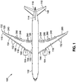
- FIG. 1 shown in Figure 1 is a top view of an aircraft 100 having a fuselage 102 and a pair of wings 116.
- Each wing 116 may be attached to the fuselage 102 at a wing root 128 and may extend from an inboard portion 130 toward an outboard portion 134 and terminating at a wing tip 132.
- the aircraft 100 may include one or more propulsion units 104 which may be mounted to the wings 116.
- the aircraft 100 may further include an empennage including a horizontal tail 108 and an elevator 110, and a vertical tail 112 and a rudder 114.
- the aircraft 100 may include one or more leading edge devices 150 and one or more trailing edge devices 240 which may be extended and retracted to alter the lift characteristics of the wings 116.
- the aircraft 100 may include leading edge devices 150 configured as slats 152 mounted to the leading edge of the wings 116.
- the leading edge devices 150 may be provided in alternative configurations such as Krueger flaps or other device configurations, and are not limited to slats 152.
- the leading edge devices 150 may include one or more inboard leading edge devices 144 and one or more outboard leading edge devices 146 such as inboard slats 154 and outboard slats 156.
- the aircraft 100 may include an autoslat system 300 for reducing the stopping distance of an aircraft 100.
- the autoslat system 300 may include an edge control system 452 configured to control a leading edge device 150 mounted to a wing of an aircraft.
- the edge control system 452 may be configured to automatically command extension of one or more leading edge devices 150 from an initial or first position to a second position in response to deployment of a spoiler 290 if a ground speed of the aircraft 100 is greater than a threshold ground speed 564.
- the second position of the leading edge device 150 may be a more deployed position than the first position, which may reduce the stopping distance 586 (see e.g., Figure 2 ) of the aircraft 100 such as during a rejected takeoff or during a landing, as described in greater detail below.
- the wings 116 may include trailing edge devices 240 such as flaps 242 or other trailing edge device 240 configurations, as shown in the example in Figure 1 . Similar to the leading edge devices 150, the trailing edge devices 240 may include inboard devices and outboard devices. For example, the inboard devices may include one or more inboard flaps 244, and an inboard roll-control flap device configured as a flaperon 286 (e.g., a combination flap-aileron). The outboard devices may include one or more outboard flaps 246 and an outboard roll-control flap device such as an aileron 288. However, the trailing edge devices 240 may be provided in other configurations including, but not limited to, elevons and other trailing edge device configurations. The aircraft 100 may also include one or more spoilers 290 on each wing 116, which may be used for generating aerodynamic drag and/or reducing wing lift.
- the inboard devices may include one or more inboard flaps 244, and an inboard roll-control flap device configured as
- FIG. 2 shown is a diagrammatic view of an aircraft 100 moving down a runway 580 such as during a takeoff roll or after landing.
- the pilot may abort the takeoff by initiating a rejected takeoff maneuver upon the occurrence of a situation, a condition, or an event as the aircraft 100 accelerates down the runway 580.
- a rejected takeoff maneuver may be initiated in the event of an engine failure, a blown tire, activation of a takeoff warning horn, instructions from air traffic control, or any one of a variety of other events that may occur during a takeoff roll.
- a rejected takeoff maneuver may be initiated prior to the aircraft 100 reaching a takeoff decision speed V 1 which may be described as a minimum speed, following an engine failure, at which a takeoff may be performed with only the remaining engines providing thrust. At speeds below the takeoff decision speed V 1 , the takeoff may be aborted by performing a rejected takeoff maneuver.
- the flight crew may reconfigure the aircraft 100 from an initial configuration 572 (e.g., a takeoff configuration) to a stopping configuration 574 so that the aircraft 100 may stop within a stopping distance 586.
- the aircraft 100 may travel a certain distance (e.g., distance 584) during the time period during which the flight crew is reconfiguring the aircraft 100 from the initial configuration 572 to the stopping configuration 574.
- the distance 584 may be described as a transition distance 584. In some instances, it may be desirable to minimize the transition distance 584, which may minimize the stopping distance 586.
- the leading edge devices 150 may be placed in the initial configuration 572 by moving the leading edge devices 150 from a retracted position 158 (shown in phantom lines) to a deployed position 160 (shown in solid lines).
- the leading edge devices 150 may comprise slats 152 which may be moved from the retracted position 158 to a partially extended and sealed position 182 during preparation for takeoff.
- a portion (e.g., an aft edge) of the slats 152 may remain in contact with the wing upper surface 122.
- one or more of the leading edge devices 150 may be maintained in a retracted position 158 or a partially-deployed position (not shown) which may or may not be sealed with the wing upper surface 122.
- one or more of the leading edge devices 150 may be moved from the retracted position 158 to a partially-gapped position (not shown).
- the spoilers 290 may be maintained in a retracted position 291 relative to a wing upper surface 122.
- the trailing edge devices 240 such as the flaps 242 may also be moved to a takeoff flaps setting 252.
- the initial configuration 572 of the aircraft 100 may comprise a landing configuration (not shown).
- one or more leading edge devices 150 may be placed in a sealed position 182 ( Figure 3 ), a partially-gapped position (not shown), or a gapped position 184 ( Figure 4 ).
- one or more leading edge devices 150 may be retained in a retracted position 158 ( Figure 3 ).
- a portion of the spoilers 290 may be maintained in a retracted position 291 ( Figure 3 ) prior to touchdown of the aircraft 100, and a portion of the spoilers 290 (e.g., flight spoilers) may be deployed ( Figure 4 ) to reduce wing lift and increase aerodynamic drag during approach in preparation for landing.
- the trailing edge devices 240 such as the flaps 242 may be moved to a takeoff flaps setting 252. Trailing edge devices 240 such as ailerons 288 ( Figure 1 ) and/or flaperons 286 ( Figure 1 ) may be maintained in a retracted position 248 when the aircraft 100 is in the initial configuration 572 (e.g., takeoff configuration). Configuring the aircraft 100 into the takeoff configuration may also include adjustment of the thrust setting of the engine control device 453 ( Figure 5 ) and/or engagement of an autothrottle (not shown).
- the takeoff roll may be initiated by moving the forward thrust levers 534 ( Figure 5 ) from the idle position 538 to a takeoff thrust position (not shown) and by releasing the wheel brakes (not shown).
- the forward thrust levers 534 may be manually moved to a takeoff thrust position and/or the forward thrust levers 534 may be moved to the takeoff thrust position via the autothrottle such that the propulsion units 104 ( Figure 1 ) generate the required thrust for accelerating the aircraft 100 down the runway 580.
- Configuring the aircraft 100 in a landing configuration for landing may include positioning the flaps 242 in a landing flaps setting 254 ( Figure 4 ) or other shallower flap setting, reducing engine thrust, extending the landing gear 106 ( Figure 2 ), arming the speedbrakes, and arming the autobrake, if included with the aircraft 100.
- the leading edge devices 150 and trailing edge devices 240 may be actuated using one or more device actuation systems 198.
- the slats 152 may be actuated by a slat actuation system 200.
- the slats 152 may be coupled to an inboard torque tube 294 or an outboard torque tube 296 or other mechanical linkage.
- the inboard torque tube 294 on the leading edge 118 may be coupled to a centrally-located, leading edge power drive unit (PDU) 402 ( Figure 10 ) as described below.
- PDU leading edge power drive unit
- Each slat 152 may be supported by one or more carrier track assemblies 202.
- Each carrier track assembly 202 may include one or more arcuate guide tracks 204 which may be supported by one or more guide rollers 206 mounted to the wing 116 structure.
- a pinion gear 208 may be mounted on the torque tube 294, 296 for engaging gear teeth (not shown) of the guide track 204.
- extension and retraction of the slats 152 may be effectuated by rotating the torque tubes 294, 296 and pinion gear 208 using the PDU 402.
- the leading edge devices 150 such as slats 152 may also be actuated by a variable camber trim unit (VCTU) 302 ( Figure 10 ) operating in conjunction with the PDU 402.
- VCTU variable camber trim unit
- a VCTU 302 may be positioned between an inboard slat 154 and an outboard slat 156 on each wing 116, and may allow for actuation of the inboard and outboard slats 154, 156 independent of one another which may advantageously reduce actuation power requirements and/or hydraulic demand at the PDU 402 during a rejected takeoff or a landing.
- actuation of the trailing edge devices 240 such as the flaps 242 may be effectuated by a flap actuation system 280 which may be operated in a manner similar to the above described slat actuation system 200.
- the flap 242 may be actuated using a trailing edge linkage assembly 282 that may be coupled to a torque tube 294, 296.
- the flap 242 actuation system 280 may include a trailing edge PDU 404 ( Figure 10 ) which may operate in conjunction with a VCTU 302 that may be positioned between an inboard flap 244 and an outboard flap 246 on each wing 116.
- the deployment and retraction of the flaps 242 may be effected by rotating the torque tubes 294, 296 using the PDU 404 and/or the VCTUs 302.
- the trailing edge device 240 in Figure 3 is shown as a simple flap 242 supported on a drop hinge 284, the flaps 242 may be provided in any one of a variety of different trailing edge device configurations including, but not limited to, a plain flap, a single-slotted flap, a multi-slotted Fowler flap, or any one of a variety of other flap configurations.
- the wing 116 may also include trailing edge devices 240 such as ailerons 288 ( Figure 1 ) and flaperons 286 ( Figure 1 ) that be actuated during a rejected takeoff or a landing.
- the ailerons 288 ( Figure 1 ) and flaperons 286 may each be actuated by dedicated actuation systems (not shown).
- the wing 116 may further include spoilers 290 mounted on the wing upper surface 122. As indicated above, one or more of the spoilers 290 may be operated as speed brakes for generating aerodynamic drag and/or reducing aerodynamic lift of the wings 116 during a rejected takeoff or a landing.
- FIG. 4 shown is a cross section of the wing 116 illustrating the slat 152 extended to the gapped position 184.
- the autoslat system 300 encompasses the extension of any type of leading edge device 150, without limitation, from any initial position to a more deployed or further deployed position.
- the autoslat system 300 encompasses the further deployment of one or more leading edge devices 150 from an initial position such as fully-retracted, stowed, partially-deployed, sealed, or partially-gapped position, to a more deployed position such as a further-deployed sealed position or to a gapped position from an initial partially-gapped position to a further deployed partially-gapped position or fully-gapped position.
- the extension of one or more leading edge devices 150 may be performed as part of the process of reconfiguring an aircraft 100 into a stopping configuration 574 during a rejected takeoff or during a landing, as described below.
- a slat 152 extended to a gapped position 184 where the slat 152 may be positioned further downwardly and forward of the wing leading edge 118 relative to the sealed position 182 ( Figure 3 ).
- Deployment of the slats 152 to the gapped position 184 results in the formation of a gap 180 between the upper aft edge of the slat 152 and the fixed leading edge of the wing 116.
- the slats 152 In the gapped position 184, the slats 152 generate increased aerodynamic drag due to exposure of a larger amount of frontal area of the slats 152 to the oncoming airflow.
- turbulent airflow over the exposed edges of the slats 152 and turbulent airflow through the gap 180 may generate increased aerodynamic drag relative to the amount of drag generated by the slats 152 in the sealed position 182.
- the slats 152 may alter the wing camber which may reduce the amount of aerodynamic lift generated by the wings 116 by altering the sectional lift characteristics of the wing airfoil sections.
- reconfiguring the aircraft 100 into the stopping configuration 574 may also include deployment of one or more of the spoilers 290 to a maximum deflection angle 293 such that increased aerodynamic drag is generated.
- the stopping configuration 574 may include deployment of all of the spoilers 290 on each wing 116 to the maximum deflection angle 293 including all of the ground spoilers and flight spoilers. Deployment of the spoilers 290 to the maximum deflection angle 293 may also reduce aerodynamic lift generated by the wings 116 allowing more of the aircraft weight to be transferred from the wings 116 to the landing gear 106 which may improve braking performance and decrease the stopping distance 586 ( Figure 2 ) of the aircraft 100.
- the trailing edge devices 240 such as flaps 242, ailerons 288, and/or flaperons 286 may also be fully extended to the maximum deflection angle 256 to generate maximum aerodynamic drag to further reduce the stopping distance 586 ( Figure 2 ).
- the process of reconfiguring the aircraft 100 into the stopping configuration 574 during a rejected takeoff or landing may also include moving the forward thrust levers 534 ( Figure 5 ) to an idle position 538 ( Figure 5 ) and disengaging an autothrottle (not shown) if included with the aircraft 100.
- the aircraft 100 may also include an autobrake system (not shown) which may be automatically engaged when the forward throttle levers are moved to the idle position 538, for example during a rejected takeoff or landing.
- An autobrake system may be configured to automatically apply a maximum braking force to the wheel brakes of the aircraft 100 which may reduce the stopping distance 586 ( Figure 2 ).
- An autobrake system may eliminate the need for the flight crew to manually apply the wheel brakes which may reduce the number of tasks that must be performed by the flight crew to reconfigure the aircraft 100 from the initial configuration 572 into the stopping configuration 574.
- the transition distance 584 may be shortened which may further reduce the stopping distance 586 ( Figure 2 ) during a rejected takeoff or landing.
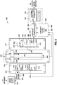
- FIG. 5 shown is a diagrammatic view of an embodiment of an autoslat system 300 configured to automatically deploy a leading edge device 150 from an initial or first position, such as a retracted position (e.g., as shown in Figure 3 ), a sealed position (e.g., as shown in Figure 4 ), or a partially-gapped position (not shown) or gapped position, to second position, which may be a further deployed position such as a further-deployed sealed position, a partially-gapped position, or a fully-gapped position 184.
- the second position may be virtually any position in which the leading edge device 150 is more deployed than in the initial position.
- the second position may be any sealed position, any partially-gapped position, or a fully-gapped position 184.
- the first or initial position is a partially deployed position, for example a sealed position
- the second position may be virtually any position in which the leading edge device 150 is more deployed than in the initial position, such as a further deployed sealed position, or a partially or fully-gapped position.
- the edge control system may be further configured to automatically command deployment of a trailing edge device 240 responsive, at least in part, to deployment of the spoiler 290 in conjunction with deployment of the leading edge device 150.
- the autoslat system 300 may include an edge control system 452 for controlling the leading edge devices 150 and the trailing edge devices 240 mounted to the wings 116.
- the autoslat system 300 may further include a thrust control system 530 for controlling a thrust setting of the one or more propulsion units 104, and a speedbrake control system 500 for controlling the spoilers 290.
- the thrust control system may be operable for selecting an idle thrust setting and a non-idle thrust setting.
- the speedbrake control system 530 may be configured to automatically command deployment of the spoiler 290 responsive, at least in part, to selection of the idle thrust setting.
- the thrust control system may include a forward thrust lever 534 positionable in at least an idle position 538 corresponding to the idle thrust setting and a non-idle position 540 corresponding to a thrust setting different than the idle thrust setting.
- the speedbrake control system 530 may be configured to automatically command deployment of the spoiler 290 responsive, at least in part, to movement of the forward thrust lever 534 from the non-idle position 540 to the idle position 538.
- the autoslat system 300 may additionally include a flight control computer 450 which may be communicatively coupled to the edge control system 452, the thrust control system 530, and the speedbrake control system 500. Any one of the edge control system 452, the thrust control system 530, the speedbrake control system 500, and/or the flight control computer 450 may be mounted on a control stand (not shown) on a flight deck of the aircraft 100. In an embodiment, the flight control computer 450 may be integrated into the edge control system 452, the thrust control system 530, and/or the speedbrake control system 500. In a further embodiment, the edge control system 452, the thrust control system 530, the speedbrake control system 500, and/or the flight control computer 450 may be integrated into a flight control system (not shown) of the aircraft 100.
- the flight control computer 450 may be configured to detect the occurrence of an autoslat condition 570, for example during a rejected takeoff or during a landing to cause automatic deployment of the one or more leading edge devices 150 from an initial position to a further deployed position. For example, in an embodiment, the flight control computer 450 may determine that an autoslat condition 570 exists when the flight control computer 450 receives an indication that the aircraft 100 is on the ground (i.e., the runway 580) and is moving in excess of a predetermined threshold ground speed 564 during a takeoff roll or landing, the forward thrust levers 534 have been moved from a non-idle position 540 to the idle position 538, and the spoilers 290 have been deployed ( Figure 4 ).
- spoiler 290 deployment may occur as a result of manual positioning of a speedbrake control device 502 (e.g., a speedbrake lever 506) into an UP detent by the pilot or flight crew, or the spoilers 290 may be automatically deployed by a speedbrake control system 500 (e.g., an auto speed brake system - not shown) in response to the pilot moving the forward thrust levers 534 from a non-idle position 540 to the idle position 538.
- a speedbrake control system 500 e.g., an auto speed brake system - not shown
- Spoilers 290 may also be automatically deployed during a landing when the speedbrake lever 506 is in the armed detent 512 and/or an airplane-on-ground 566 indication is received at the flight control computer 450 indicating that the landing gear 106 is supporting at least a portion of the aircraft 100 weight.
- the edge control system 452 may include the edge control device 453 which may be movable into any one of a plurality of control device positions 458 corresponding to leading edge device 150 (e.g., see Figures 3-4 ) settings and trailing edge device 240 settings (e.g., see Figures 3-4 ).
- the edge control system 452 may include a device actuation system 198 which may be configured to position one or more of the leading edge devices 150 and trailing edge devices 240.
- the device actuation system 198 may be configured to extend and retract the leading edge devices 150 and/or trailing edge devices 240 based on commands issued by the edge control system 452.
- the device actuation system may be configured to deploy a trailing edge device 240 to a maximum deflection angle responsive, at least in part, to deployment of the spoiler 290 in conjunction with deployment of a leading edge device 150.
- the edge control device 453 may be configured as a flap control lever 454 that may be movable along a forward-and-aft direction.
- the flap control lever 454 may be positionable at one or more control device positions 458 or flap control lever positions, although the edge control device 453 may be provided in alternative embodiments.
- the edge control device 453 may include one or more mechanical gates 456 to prevent inadvertent retraction of the leading edge devices 150 and/or the trailing edge devices 240 by requiring manual manipulation the edge control device 453 to move the edge control device 453 past the gate 456.
- control device positions 458 may include a cruise position 462 designated as UP, a hold position 464 designated as HOLD, a climb position or approach position 466 designated as CLB/APP, a takeoff position 468 or go-around position 470 designated as TOGA, and a landing position 472 designated as LAND.
- the control device positions 458 may be designated by different nomenclature and are not limited to the designations shown in Figure 6 .
- the control device positions 458 may include UP, F1, F5, F20, and F30, or the control device positions 458 may include 0, 1, 2, 3/OPT, FULL, and which may generally correspond to the above-noted UP, HOLD, CLB/APP, TOGA, and LAND control device positions 458.
- the flap control lever 454 may be moved to the takeoff position prior to the aircraft 100 initiating the takeoff roll down the runway 580.
- the trailing edge devices 240 such as the flaps 242 may move to a takeoff flaps setting 252 and the leading edge devices 150 such as the slats 152 may move to a takeoff slat setting such as the sealed position 182 ( Figure 4 ) or to a partially-gapped position.
- the takeoff slat setting for the leading edge devices 150 may comprise a stowed or retracted position 158.
- the flap control lever 454 may be moved to the landing position 472 or to a shallower flap position.
- the flight control computer 450 may analyze aircraft state data 560 to determine whether an autoslat condition 570 exists requiring the further deployment of one or more leading edge devices 150. During takeoff, the flight control computer may determine that an autoslat condition exits upon the occurrence of an event such as a blown tire, engine failure, warning horn, air traffic control instructions, or other events 582 triggering a rejected takeoff maneuver. During landing, the flight control computer 450 may determine that an autoslat condition 570 exits when an indication is received by the flight control computer 450 that the landing gear 106 is supporting at least a portion of the aircraft 100 weight, and the spoilers 290 are deployed.
- an event such as a blown tire, engine failure, warning horn, air traffic control instructions, or other events 582 triggering a rejected takeoff maneuver.
- the flight control computer 450 may determine that an autoslat condition 570 exits when an indication is received by the flight control computer 450 that the landing gear 106 is supporting at least a portion of the aircraft 100 weight, and
- the edge control system 452 may automatically command the device actuation system 198 to further deploy the leading edge devices 150 from their initial position to a further deployed position upon the occurrence of the autoslat condition 570.
- the edge control system 452 may also command the device actuation system 198 to move the trailing edge devices 240 (e.g., flaps 242, ailerons 288, flaperons 286) to the maximum deflection angle 256 regardless of the position of the flap control lever 454 prior to initiation of the rejected takeoff or prior to the landing.
- the maximum deflection angle 256 may correspond to the landing flaps setting 254 ( Figure 4 ).
- the autoslat system 300 may include the thrust control system 530 which may include one or more forward thrust levers 534 and one or more reverse thrust levers 532.
- the forward thrust levers 534 may be advanced from an idle position 538 to a non-idle position 538 corresponding to a desired thrust setting of the propulsion units 104 ( Figure 1 ).
- the reverse thrust levers 532 may be coupled to the forward thrust levers 534 and may allow for controlling engine reverse thrust via thrust reversers (not shown) on the propulsion units 104 and which may be activated when the forward thrust levers 534 are in the idle position 538.
- the thrust control system 530 may be communicatively coupled to the flight control computer 450.
- the thrust control system 530 may provide an indication to the flight control computer 450 when the forward thrust levers 534 are moved by the pilot or other flight crew from a non-idle position 540 to the idle position 538 during the initiation of a rejected takeoff or during a landing.
- the autoslat system 300 may further include the above-mentioned speedbrake control system 500 which may be communicatively coupled to the flight control computer 450.
- the speedbrake control system 500 may include a speedbrake control device 502 and a spoiler actuation system 504 for deploying the spoilers 290.
- the speedbrake control device 502 may be configured as a speedbrake lever 506 and may have a plurality of speedbrake detents 508 which may represent a deflection angle for the spoilers 290 ( Figure 4 ).
- the speedbrake detents 508 may include a down detent 510 designated as DOWN, an armed detent 512 designated as ARMED, a flight detent 514 designated as FLIGHT DETENT, and an up detent 516 designated as UP.
- the speedbrake control device 502 may include a larger or smaller quantity of speedbrake detents 508.
- the speedbrake detents 508 may be designated by different nomenclature and are not limited to the illustrated designations in Figure 5 .
- one or more of the spoilers 290 may be deployed to a maximum deflection angle 293 in response to the pilot or other flight crew member manually moving the speedbrake control device 502 to the UP detent to cause the spoiler actuation system 504 to deploy the spoilers 290.
- the spoilers 290 on each wing 116 may be deployed substantially simultaneously to the maximum deflection angle 293.
- the speedbrake control system 500 may automatically command the spoiler actuation system 504 to deploy the spoilers 290 when the flight control computer 450 receives an indication that the forward thrust levers 534 have been moved from a non-idle position 540 (e.g., a takeoff thrust setting) to the idle position 538 and/or the aircraft 100 is on the ground and is moving in excess of a threshold ground speed 564.
- a non-idle position 540 e.g., a takeoff thrust setting
- the flight control computer 450 may receive aircraft state data 560 regarding the state of the aircraft 100 during the takeoff roll or landing.
- the aircraft state data 560 may include the above-mentioned airplane-on-ground 566 indication, an indication of the actual ground speed 562 of the aircraft 100, an indication of movement of the forward thrust levers 534 to the idle position 538, and an indication of the speedbrake setting 568 representing deployment of the spoilers 290.
- the airplane-on-ground 566 indication may be provided by one or more sensors (not shown) on the landing gear 106 (not shown) which may sense spin-up of the wheels, compression of landing gear struts, tilt of the landing gear trucks, or other parameters indicating that the landing gear 106 is supporting at least a portion of the aircraft 100 weight.
- One or more ground speed sensors may transmit an indication of the aircraft 100 actual ground speed 562 to the flight control computer 450.
- the flight control computer 450 may compare the actual ground speed 562 to a predetermined threshold ground speed 564, and determine whether the actual ground speed 562 exceeds the threshold ground speed 564.
- the thrust control system 530 may transmit to the flight control computer 450 an indication of movement of the forward thrust levers 534 from a non-idle position 540 to the idle position 538.
- the speedbrake control system 500 may transmit an indication to the flight control computer 450 regarding the deployment of the spoilers 290 from the retracted position 291 ( Figure 3 ) to the deployed position 160 ( Figure 4 ).
- the flight control computer 450 may analyze the above-noted aircraft state data 560 to determine whether the autoslat condition 570 exists.
- the flight control computer 450 may transmit a signal to the edge control system 452 to cause the edge control system 452 to automatically command the device actuation system 198 to further deploy the leading edge devices 150 from their initial position in preparation for takeoff or their initial position in preparation for landing.
- the edge control system 452 may automatically command the device actuation system 198 to extend the leading edge devices 150 when the spoilers 290 are automatically deployed (i.e., using the auto speed brake) by the spoiler actuation system 504 in response to the forward thrust levers 534 being moved to the idle position 538.
- the further deployment of the leading edge devices 150 may advantageously alter the wing camber which may alter (e.g., reduce) the sectional lift characteristics of the wings 116 which may improve the stopping performance of the aircraft 100 and reduce the stopping distance 586 ( Figure 2 ).
- autogapping of the leading edge devices 150 during a rejected takeoff may provide an estimated 5,000-10,000 pounds of additional weight on the aircraft wheels which may improve braking performance and reduce takeoff field length by up to approximately 50 feet or more.
- further deployment of the leading edge devices 150 may increase aerodynamic drag.
- the transition time and transition distance 584 ( Figure 2 ) may be minimized.
- the autoslat system 300 may be configured such that the edge control system 452 automatically deploys the trailing edge devices 240 upon deployment of the spoilers 290 from the retracted position 291 to the deployed position 292.
- the autoslat system 300 may be configured such that the edge control system 452 automatically deploys the trailing edge devices 240 in conjunction with the further deployment of the leading edge devices 150.
- Trailing edge devices 240 that may be automatically deployed may include the flaps 242, the ailerons 288, and/or the flaperons 286 ( Figure 1 ).
- the flaps 242, ailerons 288, and/or flaperons 286 may be automatically deployed such as from a retracted position 248 to a maximum deflection angle 256 in a deployed position 250 upon deployment of the spoilers 290 from the retracted position 291 to the deployed position 292. Movement of the trailing edge devices 240 to the maximum deflection angle 256 may increase aerodynamic drag which may shorten the stopping distance 586 ( Figure 2 ) of the aircraft 100 during a rejected takeoff or a landing.
- FIG. 6-9 shown are diagrammatic views of an embodiment of the autoslat system 300 allowing for further deployment of the inboard and outboard leading edge devices 144, 146 independent of one another.
- the device actuation system may be configured to actuate the inboard leading edge device 144 independently of the outboard leading edge device 146, and vice versa.
- actuation power requirements may be reduced.
- the total power requirements and/or hydraulic demand for actuating the leading edge devices 150 may be reduced relative to higher power requirements and greater hydraulic demand for further deploying all of leading edge devices 150 at one time.
- reduced power requirements and reduced hydraulic demand may be advantageous in the event of an engine-out situation during a rejected takeoff or landing.
- An engine-out situation may result in reduced availability of power for actuating the spoilers 290, the leading and trailing edge devices 150, 240, and other systems due to the inability of the non-operative engine to generate power and/or hydraulic pressure.
- a VCTU 302 may be positioned between an inboard and outboard leading edge device 144, 146 to allow for independent actuation of the inboard and outboard leading edge devices 144, 146.
- a VCTU 302 may also be positioned between an inboard trailing edge device 240 and outboard trailing edge device 240 to allow for independent actuation of the inboard and outboard trailing edge devices 240.
- the VCTU 302 may allow for further deployment of a subset of the leading edge devices 150 upon the occurrence of an autoslat condition 570 ( Figure 5 ).
- a VCTU 302 positioned between the inboard slats 154 and the outboard slats 156 may allow for automatically moving the outboard slats 156 to a further deployed position while the inboard slats 154 are held stationary.
- the outboard slats 156 may be automatically deployed to a gapped position 184 ( Figure 4 ) while the inboard slats 154 are momentarily retained in a sealed position 182 ( Figure 3 ).
- the inboard slats 154 may then be automatically moved to a further deployed position (e.g., the gapped position 184).
- the VCTUs may operate in conjunction with the PDUs 400 to automatically deploy the inboard and outboard slats 154, 156 in unison.
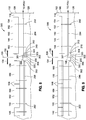
- FIG. 6 shown is diagrammatic plan view of a leading edge 118 of a wing 116 schematically illustrating a VCTU 302 positioned between an inboard leading edge device 144 (e.g., an inboard slat 154) and outboard leading edge devices 146 (e.g., outboard slats 156).
- the inboard slats 154 may be coupled to an inboard torque tube 294 and the outboard slats 156 may be coupled to an outboard torque tube 296.
- the VCTU 302 may include a dedicated electric motor 304 which may be operated in conjunction with the speed sum gearbox 320 and an outboard brake 354.
- the inboard slat 154 may be driven by a central motor 406 ( Figure 11 ) of a leading edge PDU 402 ( Figure 11 ).
- the VCTU 302 may be included with the device actuation system 198 and may be operated in conjunction with the PDU 402 to automatically deploy the inboard and outboard leading edge devices 144, 146 independent of one another.
- FIG 7 shown is a diagrammatic view of the wing 116 leading edge 118 of Figure 6 illustrating the operation of the VCTU 302 in conjunction with the leading edge PDU 402 to further deploy the inboard and outboard slats 154, 156 in unison from their initial position.
- the power-off brake 310 of the VCTU 302 may be applied to prevent rotational movement of the electric motor 304.
- the central motor 406 ( Figure 11 ) of the leading edge PDU 402 ( Figure 11 ) may be activated for actuating the inboard slat 154.
- actuation of the inboard slat 154 by the central motor 406 of the leading edge PDU 402 may rotate the inboard torque tube 294.
- the rotational movement of the inboard torque tube 294 may be transferred through the speed sum gearbox 320 to the outboard torque tube 296 resulting in actuation of the inboard slat 154 and the outboard slat 156 in unison.
- FIG 8 shown is a diagrammatic view of the wing 116 leading edge 118 of Figure 6 illustrating the further deployment of the inboard slat 154 independently of the outboard slats 156.
- the power-off brake 310 of the electric motor 304 may be released.
- the outboard brake 354 of the VCTU 302 may be applied to prevent rotation of the outboard slats 156.
- the central motor 406 ( Figure 11 ) of the leading edge PDU 402 ( Figure 11 ) may be activated resulting in rotation of the inboard torque tube 294.
- the speed sum gearbox 320 of the electric motor 304 may be configured such that rotation of the inboard torque tube 294 causes the electric motor 304 to be back-driven while the inboard slat 154 is actuated by the central motor 406 of the leading edge PDU 402.
- the autoslat system 300 may be configured such that the edge control system 452 automatically commands the device actuation system 198 to extend one or more outboard leading edge devices 146 (e.g., the outboard slats 156) such as from the sealed position 182 ( Figure 4 ) to a further-deployed sealed position, partially-gapped position, or gapped position 184 ( Figure 5 ) prior to further deploying one or more inboard leading edge devices 144 (e.g., the inboard slat 154).
- the edge control system 452 automatically commands the device actuation system 198 to extend one or more outboard leading edge devices 146 (e.g., the outboard slats 156) such as from the sealed position 182 ( Figure 4 ) to a further-deployed sealed position, partially-gapped position, or gapped position 184 ( Figure 5 ) prior to further deploying one or more inboard leading edge devices 144 (e.g., the inboard slat 154).
- the central motor 406 of the leading edge PDU 402 may be prevented from rotating the inboard slat 154 by applying a central brake 414 which may be coupled to the central motor 406.
- the outboard brake 354 of the VCTU 302 may be released.
- the power-off brake 310 of the electric motor 304 may be released.
- the electric motor 304 may then be activated causing rotation of the outboard torque tube 296 and resulting in deployment of the outboard slats 156 independently of the inboard slat 154.
- the edge control system 452 may automatically command the VCTU motor controller 303 to activate the electric motor 304 in a manner causing the outboard slats 156 to be further extended.
- the outboard brake 354 of the VCTU 302 may be applied.
- the power-off brake 310 of the VCTU electric motor 304 released, the central brake 414 of the leading edge PDU 402 may be released and the central motor 406 of the leading edge PDU 402 may be activated causing the inboard torque tube 294 to rotate. Rotation of the inboard torque tube 294 may cause the inboard slat 154 to be further extended while the outboard slats 156 are stationary.
- the VCTU electric motor 304 may be back-driven while the inboard slat 154 is further deployed.
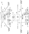
- FIG. 10 shown is a diagrammatic view of a device actuation system 198 incorporating VCTUs 302 between the inboard leading edge devices 144 and outboard leading edge devices 146 on the leading edge 118 of each wing 116 of the aircraft 100.
- a similar arrangement of VCTUs 302 may be implemented with the trailing edge devices 240.
- the device actuation system 198 may include a leading edge PDU 402 coupled to the leading edge devices 150 on opposite sides of the fuselage 102, and a trailing edge PDU 404 coupled to the trailing edge devices 240 on opposite sides of the fuselage 102.
- the device actuation system 198 may be controlled by flight control electronics 422 which may be centrally-located on the aircraft 100 and/or may be positioned adjacent to one or both of the PDUs 400.
- the flight control electronics 422 may be configured to generate command signals for actuating the leading edge devices 150 and the trailing edge devices 240.
- the command signals may be transmitted via one or more command lines 424 or wirelessly transmitted to the leading edge PDU 402, the trailing edge PDU 404, and to the motor controller 303 of each VCTU 302.
- each motor controller 303 may control the VCTU electric motor 304, the outboard brake 354, and/or the power-off brake 310 of the VCTU 302.
- the flight control electronics 422 may transmit command signals to the motor controller 303 of the VCTU electric motor 304 and to the central motor 406 causing actuation (e.g., deployment and retraction) of the inboard leading edge devices 144 and the outboard leading edge devices 146.
- the flight control electronics 422 may receive position signals from one or more position sensors 312 (see e.g., Figure 13 ) that may be included with each one of the VCTUs 302.
- the position signals may represent the current position or deflection angle of each one of the inboard leading edge devices 144.
- the device actuation system 198 may further include a central power supply 426 for powering the VCTU electric motor 304 of each one of the VCTUs 302.
- the power supply 426 may be centrally-located such as adjacent to the PDUs 400.
- each VCTU electric motor 304 may include the above-mentioned motor controller 303 which may be powered by the central power supply 426 with a substantially continuous supply of relatively low-voltage power. Such low-voltage power may be removed from the motor controller 303 for certain types of faults.
- Relatively high-voltage power may be provided to the VCTU electric motors 304 from the central power supply 426 via an electric supply line 428 to cause the VCTU electric motor 304 to rotate such as in response to a command signal transmitted along a command line 424 from the flight control electronics 422 to the motor controller 303.
- each one of the VCTUs 302 may include a VCTU electric motor 304 and a speed sum gearbox 320.
- An outboard brake 354 may be included with each VCTU 302 to prevent rotation of the outboard device 146 as indicated above.
- the VCTU 302 may include the above-mentioned power-off brake 310 which may be coupled to the VCTU electric motor 304 and which may be applied by one or more coils 318.
- the coils 318 may receive power from the centrally-located central power supply 426 via an electric supply line 428 for activating the power-off brake 310 such as in response to a command signal received from the flight control electronics 422 via a command line 424.
- One or more resolvers 316 may be included at different locations on the leading edge devices 150 and/or trailing edge devices 240 for indicating the positions of such devices 150, 240 and which may be provided to the flight control electronics 422.
- FIG 11 is a diagrammatic view of a center portion of the variable camber actuation system showing the leading edge PDU 402 and the trailing edge PDU 404.
- the leading edge PDU 402 and the trailing edge PDU 404 may be coupled to the inboard torque tubes 294 on the respective leading edge 118 and trailing edge 120 of each wing 116.
- each one of the PDUs 400 may include at least one central motor 406.
- each one of the PDUs 400 may include an active motor 408 and a backup motor 410.
- Each one of the central motors 406 may be coupled to or may include a central brake 414 configured as a power-off brake for preventing rotation of the central motor 406 and thereby preventing actuation of the inboard device 144 to which the central motor 406 is coupled.
- a central brake 414 configured as a power-off brake for preventing rotation of the central motor 406 and thereby preventing actuation of the inboard device 144 to which the central motor 406 is coupled.
- the active motor 408 and/or the backup motor 410 may be configured as a hydraulic motor or an electrohydraulic actuator which may be coupled to a central hydraulic system 418 via one or more hydraulic lines 420.
- the active motor 408 and/or the backup motor 410 may optionally be configured as an electromechanical actuator or an electric motor for controlling the actuation of the inboard devices.
- the central motors 406 of the leading edge PDU 402 may be coupled to the inboard torque tubes 294 for driving the inboard leading edge devices 144.
- the trailing edge PDU 404 may be coupled to the inboard devices on the trailing edge 120 in a manner similar to the leading edge PDU 402.
- Each one of the PDUs 400 may include a central gearbox 412 and one or more central brakes 414.
- Each one of the central motors 406 may be coupled to the central brake 414 (e.g., a power-off brake) which may be configured to prevent movement of the inboard devices when both central brakes 414 are applied.
- the central brake 414 e.g., a power-off brake
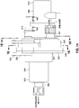
- FIG 12 is a schematic diagram of an embodiment of a VCTU 302 illustrating the interconnection of the speed sum gearbox 320 with the outboard brake 354, the VCTU electric motor 304 and power-off brake 310, and the position sensor 312.
- the arrangement of the VCTU 302 is described below in the context of the inboard and outboard leading edge devices 144, 146, and may be implemented in a similar manner for the trailing edge devices 240.
- the speed sum gearbox 320 includes an inboard shaft 351 that may be coupled to an inboard leading edge device 144 via an inboard torque tube 294, and an outboard shaft 352 that may be coupled to an outboard leading edge device 146 via an outboard torque tube 296.
- the VCTU electric motor 304 may include a motor shaft 306 having a motor pinion 308 that may be engaged to a ring gear 338 of the speed sum gearbox 320.
- the speed sum gearbox 320 may be configured such that if one of the three shafts (i.e., the inboard shaft 351, the outboard shaft 352, the motor shaft 306) is held stationary and prevented from rotating, the remaining pair of shafts will rotate under the driving force of one of the remaining shafts of the pair. For example, if the inboard shaft 351 is prevented from rotating due to application of the central brake 414 of the PDU, then rotation of the motor shaft 306 will cause rotation of the outboard shaft 352 resulting in actuation of the outboard leading edge device 146 independent of the inboard leading edge device 144.
- the inboard shaft 351 may be fixedly (e.g., non-rotatably) coupled to the inboard device 144 via the inboard torque tube 294.
- the outboard shaft 352 may be fixedly (e.g., non-rotatably) coupled to the outboard device 146 via the outboard torque tube 296.
- the inboard shaft 351 may include an inboard pinion 334 that may be coupled to an inboard gear 332 of the speed sum gearbox 320.
- the inboard gear 332 may be mounted on or fixedly (i.e., non-rotatably) coupled to a sun gear shaft 350 of a sun gear 346 of the speed sum gearbox 320.
- the position sensor 312 may include a position sensor gear 314 that may be engaged to the inboard gear 332 for sensing a position of the inboard leading edge device 144 and transmitting a position signal to the flight control electronics 422.
- the speed sum gearbox 320 may include a plurality of planet gears 344 that may be supported on a carrier 348.
- the carrier 348 may be fixedly (i.e., non-rotatably) coupled to or mounted on the outboard shaft 352.
- the planet gears 344 may encircle and may be engaged to the sun gear 346.
- the plurality of planet gears 344 may be circumscribed by a ring gear 338.
- the motor pinion 308 may be engaged to an external side 342 of the ring gear 338.
- FIG. 13 is a perspective illustration of an embodiment of the VCTU 302 and showing the inboard torque tube 294 coupled to the inboard shaft 351 and the outboard torque tube 296 coupled to the outboard shaft 352 of the speed sum gearbox 320.
- the VCTU 302 may comprise an integrated unit including the VCTU electric motor 304 and associated power-off brake 310, outboard brake 354, and position sensor 312, all of which may be supported by or enclosed, at least partially, within the VCTU housing 322.
- the VCTU housing 322 may include one or more mounting tabs 324 for mounting the VCTU 302 to the wing 116 structure of an aircraft 100.
- Figure 14 is a forward-looking view of the VCTU 302 illustrating the VCTU housing 322.
- the VCTU housing 322 may be made up of an inner housing 326 on the inboard side of the VCTU 302, an outer housing 330 on an outboard side of the VCTU 302, and a mid housing 328 sandwiched between the inner housing 326 and the outer housing 330.
- the inner housing 326, the mid housing 328, and the outer housing 330 may be mechanically coupled together such as with mechanical fasteners.
- the three-piece arrangement of the VCTU housing 322 may facilitate assembly and disassembly of the VCTU 302 such as for maintenance and inspection.
- the VCTU housing 322 may be sealed from the elements by a seal extending around a perimeter at the interface of the housings.
- the VCTU housing 322 may be configured to provide a relatively rigid load path for operational loads.
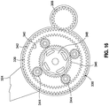
- Figure 15 is a sectional view of the VCTU 302 showing the inboard pinion 334 and the position sensor gear 314 operatively engaged to one another by the inboard gear 332.
- the inboard gear 332 may be omitted, and the inboard shaft 351 may be directly coupled to the sun gear 346.
- the position sensor gear 314 may be engaged to another gear (not shown) that may be mounted on or integrally formed with the inboard shaft 351 to allow the position sensor 312 to sense the position of the inboard device 144 for transmitting a representative position signal to the flight control electronics 422.
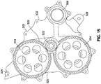
- FIG 16 is a sectional view of the VCTU 302 showing the speed sum gearbox 320 configured as a planetary gear system 336.
- the speed sum gearbox 320 includes a central sun gear 346 having gear teeth and which is surrounded by a plurality of planet gears 344.
- the planet gears 344 are supported on the carrier 348 which may be fixedly mounted to the outboard shaft 352.
- the gear teeth of the planet gears 344 are engaged to the gear teeth on the internal side 340 of the ring gear 338 which circumscribes the planet gears 344.
- the motor pinion 308 of the VCTU electric motor 304 are engaged to the external side 342 of the ring gear 338.
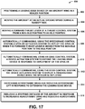
- Step 602 of the method may include positioning a leading edge device 150 of an aircraft wing 116 in an initial position such as a partially extended and sealed position 182 during preparation for takeoff or landing.
- a portion of the slats 152 e.g., the aft edge of the slats
- the leading edge devices 150 may be maintained in a retracted position 158 ( Figure 3 ) or a gapped position.
- the process of configuring the aircraft 100 in the initial configuration 572 may also include moving the flaps 242 to a desired flap setting such as the takeoff flaps setting 252 shown in Figure 4 or the landing flaps setting shown in Figure 5 .
- the spoilers 290 may be maintained in the retracted position 291 as may the trailing edge devices such as the ailerons 288 and flaperons 286.
- Step 604 of the method 600 of Figure 17 may include advancing the forward thrust levers 534 ( Figure 5 ) from an idle position 538 to a non-idle position 540 such as to a takeoff thrust position (not shown) for takeoff, and to a reduced thrust setting non-idle position 540 for landing.
- the wheel brakes may be released allowing the thrust from the propulsion units 104 to accelerate the aircraft 100 down the runway 580.
- the method may include moving the aircraft 100 at an actual ground speed 562 during the takeoff roll or upon touchdown during a landing. As indicated above, an indication of the actual ground speed 562 may be continuously provided to the flight control computer 450 during the takeoff roll.
- Step 606 of the method 600 of Figure 17 may include moving one or more of the forward thrust levers 534 of the thrust control system 530 from the non-idle position 540 to the idle position 538 to initiate a rejected takeoff.
- the initiation of the rejected takeoff may include disengaging an autothrottle (not shown) which may result in activation of an autobrake system (not shown) to automatically apply maximum braking force to the wheels.
- the pilot or other flight crew member may initiate a rejected takeoff upon the occurrence of an event such as an engine failure, a blown tire, activation of a takeoff warning horn, instructions from air traffic control, or other events that may occur during the takeoff roll.
- Touchdown of the main landing gear 106 during a landing may also activate the autobrake system to automatically apply braking force to the wheels.
- moving one or more of the forward thrust levers to the idle position 538 after the main landing gear 106 touches down may also activate the autobrake system.
- Step 608 of the method 600 of Figure 17 may include deploying the spoilers 290 responsive, at least in part, to moving the forward thrust levers 534 from the non-idle position 540 to the idle position 538.
- the method may include automatically commanding, using the speedbrake control system 500, the spoiler actuation system 504 to deploy the spoilers 290 when the forward thrust lever 534 is moved from the non-idle position 540 to the idle position 538.
- the spoilers 290 may be deployed at the maximum deflection angle 293 to maximize aerodynamic drag and minimize aerodynamic lift of the wings 116.
- the automatic deployment of the spoilers 290 may be included as part of an auto speed brake capability of the aircraft 100, and may be triggered when it is determined by the flight control computer 450 that the aircraft 100 is on the ground and the actual ground speed 562 exceeds the threshold ground speed 564 which may be preprogrammed into the flight control computer 450.
- a selected threshold ground speed 564 (e.g., 85 knots) may be preprogrammed into the flight control computer 450.
- the flight control computer 450 may receive an indication of the actual ground speed 562 of the aircraft 100 for comparison to the threshold ground speed 564.
- the flight control computer may send a signal to the speedbrake control system 500 causing the speedbrake control system 500 to automatically command the speed actuation system to deploy the spoilers 290.
- Step 610 of the method 600 of Figure 17 may include automatically commanding, using the edge control system 452, the device actuation system 198 to further deploy the leading edge devices 150. If the actual ground speed 562 of the aircraft 100 exceeds the threshold ground speed 564, the method may include automatically commanding the leading edge devices 150 from a first position to a second position in response to deployment of the spoilers 290.
- the first position of the leading edge devices 150 may be a retracted position 158, a sealed position 182, or a partially-gapped or gapped position 184.
- the second position of the leading edge devices 150 may be a sealed position 182 or a gapped position 184.
- the autoslat system 300 may be configured to automatically move the leading edge devices 150 from any initial position (e.g., stowed, sealed, gapped) to a further deployed position (e.g., sealed, gapped) when the spoilers 290 are manually or automatically commanded to the deployed position 292.
- the spoilers 290 may also be manually deployed by the pilot manually moving the speedbrake lever 506 to the UP detent ( Figure 5 ).
- the spoilers 290 may also be automatically commanded to the deployed position 292 in response to the forward thrust levers 534 being moved to the idle position 538 as part of an auto speed brake capability of the aircraft 100 during a rejected takeoff or a landing, and/or in response to an airplane-on-ground 566 indication during a landing.
- the edge control system 452 may automatically command the device actuation system 198 to further extend an inboard leading edge device 144 and an outboard leading edge device 146 independent of one another.
- the method may include moving an inboard leading edge device 144 independently of an outboard leading edge device 146.
- the method may include extending the outboard leading edge device 146 prior to extending the inboard leading edge device 144 by operating the VCTUs 302 in conjunction with the leading edge PDUs 402. Independent actuation of the inboard and outboard leading edge devices 144, 146 may reduce actuation power requirements and/or hydraulic demand for the device actuation systems 198.
- Step 612 of the method 600 of Figure 17 may include deploying a trailing edge device 240 responsive, at least in part, to the deployment of the spoiler 290.
- the method may include automatically commanding, using the edge control system 452, the device actuation system 198 to deploy one or more trailing edge devices 240 when the spoilers 290 are deployed.
- the device actuation system 198 for the trailing edge devices 240 may automatically command the flaps 242 to the maximum deflection angle 256 which may correspond to the landing flaps setting 254 shown in Figure 4 .
- the flaps 242 may also be differentially actuated to the maximum deflection angle 256 using VCTUs 302 operating in conjunction with the trailing edge PDU 404 in a manner similar to the above-described system for independently actuating the leading edge devices 150.
- the deployment of the spoilers 290 may also initiate the automatic deflection of the ailerons 288, flaperons 286, and other trailing edge devices 240 to the maximum deflection angle 256.
- Step 614 of the method 600 of Figure 17 may include reducing aerodynamic lift of the wings 116 and/or increasing aerodynamic drag in response to further extending the leading edge devices 150 and deploying the spoilers 290 and the trailing edge devices 240 to the maximum deflection angle 256, 293.
- further deployment of the leading edge devices 150 may alter the wing camber resulting in a reduction in aerodynamic lift of the wings 116.
- further deployment of the leading edge devices 150 may increase aerodynamic drag due to a larger frontal area of the leading edge devices 150, and due to turbulent airflow over the edges of the leading edge devices 150 and through the gap 180 ( Figure 2 ).
- Step 616 of the method 600 of Figure 17 may include reducing the stopping distance 586 ( Figure 2 ) of the aircraft 100 in response to reducing the aerodynamic lift of the wings 116 and increasing the aerodynamic drag of the aircraft 100.
- the lift generated by the wings 116 may be reduced by the further-deployed leading edge devices 150 which may alter the sectional lift characteristics of the wings resulting in a transfer of a portion of the aircraft 100 weight from the wings 116 to the landing gear 106 which may improve braking performance during a rejected takeoff or a landing. Additional modifications and improvements of the present disclosure may be apparent to those of ordinary skill in the art.
- the particular combination of parts described and illustrated herein is intended to represent only certain embodiments of the present disclosure and is not intended to serve as limitations of alternative embodiments or devices within the spirit and scope of the disclosure.
- a system for reducing a stopping distance of an aircraft comprising an edge control system configured to control a leading edge device mounted to a wing of an aircraft; the edge control system configured to automatically command extension of the leading edge device from a first position to a second position in response to deployment of a spoiler if a ground speed of the aircraft is greater than a threshold ground speed.
- first position is a retracted position, a sealed position, or a gapped position
- second position is a sealed position or a gapped position
- the system disclosed further comprising a thrust control system operable for selecting an idle thrust setting and a non-idle thrust setting; and a speedbrake control system configured to automatically command deployment of the spoiler responsive, at least in part, to selection of the idle thrust setting.
- the thrust control system includes a thrust lever positionable in at least an idle position corresponding to the idle thrust setting and a non-idle position corresponding to a thrust setting different than the idle thrust setting; and wherein the speedbrake control system is configured to automatically command deployment of the spoiler responsive, at least in part, to movement of the thrust lever from the non-idle position to the idle position.
- edge control system is further configured to automatically command deployment of a trailing edge device responsive, at least in part, to deployment of the spoiler in conjunction with deployment of the leading edge device.
- the system disclosed further comprising a device actuation system communicatively coupled to the edge control system and configured to actuate the leading edge device and/or the trailing edge device; and the device actuation system is configured to deploy the trailing edge device to a maximum deflection angle responsive, at least in part, to deployment of the spoiler in conjunction with deployment of the leading edge device.
- the trailing edge device comprises at least one of a flap, an aileron, and a flaperon.
- the system disclosed further comprising a device actuation system communicatively coupled to the edge control system; wherein the leading edge device is one of a plurality of leading edge devices coupled to the wing, the plurality of leading edge devices including an inboard leading edge device and an outboard leading edge device; and the device actuation system is configured to actuate the inboard leading edge device independently of the outboard leading edge device.
- edge control system is configured to automatically command the device actuation system to extend the outboard leading edge device prior to extending the inboard leading edge device.
- the system disclosed wherein the device actuation system includes a variable camber trim unit (VCTU) positioned between the inboard leading edge device and the outboard leading edge device; and the VCTU actuating the outboard leading edge device independent of the inboard leading edge device.
- VCTU variable camber trim unit
- the VCTU includes a speed sum gearbox including an inboard shaft coupled to the inboard leading edge device and an outboard shaft coupled to the outboard leading edge device; a VCTU electric motor engaged to the speed sum gearbox; and wherein the VCTU electric motor selectively operating in conjunction with the speed sum gearbox to rotate the outboard shaft independent of the inboard shaft in a manner causing the outboard leading edge device to be actuated independent of the inboard leading edge device.
- an autoslat system for reducing a stopping distance of an aircraft, comprising an edge control system including a device actuation system configured to position a leading edge device mounted to a wing of an aircraft; a thrust control system including a forward thrust lever positionable in one of an idle position and a non-idle position; a speedbrake control system automatically commanding a spoiler actuation system to deploy a spoiler when the forward thrust lever is moved from the non-idle position to the idle position and the aircraft is on ground and moving in excess of a threshold ground speed; and the edge control system automatically commanding the device actuation system to extend the leading edge device when the spoiler is deployed automatically by the spoiler actuation system in response to the forward thrust lever being moved to the idle position.
- a method of reducing a stopping distance of an aircraft comprising deploying a spoiler mounted on a wing of an aircraft; and if a ground speed of the aircraft exceeds a threshold ground speed, automatically commanding a leading edge device on the wing of the aircraft from a first position to a second position in response to deployment of the spoiler.
- first position is a retracted position, a sealed position, or a gapped position and the second position is a sealed position or a gapped position.
- the method disclosed wherein the step of deploying the spoiler includes moving a thrust lever from a non-idle position to an idle position; and deploying the spoiler responsive, at least in part, to moving the thrust lever from the non-idle position to the idle position.
- the method disclosed further comprising deploying a trailing edge device responsive, at least in part, to the deployment of the spoiler.
- the method disclosed wherein the step of deploying the trailing edge device includes deploying the trailing edge device to a maximum deflection angle.
- the trailing edge device comprises at least one of a flap, an aileron, and a flaperon.
- the method disclosed further comprising moving an inboard leading edge device independently of an outboard leading edge device.
- the method disclosed further comprising extending the outboard leading edge device prior to extending the inboard leading edge device.
Landscapes
- Engineering & Computer Science (AREA)
- Aviation & Aerospace Engineering (AREA)
- Mechanical Engineering (AREA)
- Automation & Control Theory (AREA)
- Traffic Control Systems (AREA)
- Transmission Devices (AREA)
- Control Of Position, Course, Altitude, Or Attitude Of Moving Bodies (AREA)
- Radar, Positioning & Navigation (AREA)
- Remote Sensing (AREA)
- Physics & Mathematics (AREA)
- General Physics & Mathematics (AREA)
Description
- The present disclosure relates generally to control surfaces of an aircraft and, more particularly, to the positioning of control surfaces of a wing during a rejected takeoff or a landing.
- During takeoff of an aircraft, a pilot may need to perform a rejected takeoff maneuver for any one of a variety of different reasons. For example, as the aircraft accelerates down the runway, the pilot may receive an indication of an engine failure or a blown tire. Alternatively, a takeoff warning horn may be activated on the flight deck or instructions may be received from air traffic control to abort the takeoff.
- For aircraft certification, the Federal Aviation Administration (FAA) requires that when a rejected takeoff is initiated below a takeoff decision speed, the aircraft must be capable of safely stopping before the end of the runway. Upon initiation of a rejected takeoff, the pilot and other flight crew members may reconfigure the aircraft from an initial configuration to a stopping configuration. For example, engine thrust may be reduced to idle and speedbrakes (e.g., spoilers) may be deployed to generate aerodynamic drag to reduce the stopping distance.
- Certain aircraft may include an autobrake system which may automatically apply maximum braking force to the aircraft wheel brakes upon the initiation of a rejected takeoff. The autobrake system may reduce the number of tasks required by the flight crew to reconfigure the aircraft into the stopping configuration which may further reduce the stopping distance. Although an autobrake system may reduce the stopping distance, aircraft initiating a rejected takeoff near the takeoff decision speed may require increased stopping capability to maximize the performance of the aircraft.
- In United States Patent
3,618,880 , there is described a system for allowing automatic or overriding manual actuation of an aircraft's spoilers. - As can be seen, there may be a need in the art for systems and methods, which may improve the stopping performance of an aircraft.
- In accordance with the present invention, there is disclosed a system and method for reducing a stopping distance of an aircraft, as set out in the appended claims.
- The present disclosure describes a system, also referred to herein as an autoslat system, for reducing a stopping distance of an aircraft, for example during a rejected takeoff or a landing. The autoslat system may include an edge control system configured to control a leading edge device mounted to a wing of an aircraft. The autoslat system may include a speedbrake control system operable to deploy a spoiler mounted to the wing. The edge control system may be configured to automatically command extension of the leading edge device from a first position to a second position in response to deployment of a spoiler if a ground speed of the aircraft is greater than a threshold ground speed.
- In a further embodiment, disclosed is an autoslat system including an edge control system having a device actuation system configured to position a leading edge device mounted to a wing of an aircraft. The autoslat system may include a thrust control system having a forward thrust lever positionable in one of an idle position and a non-idle position. The autoslat system may also include a speedbrake control system automatically commanding a spoiler actuation system to deploy a spoiler when the forward thrust lever is moved from the non-idle position to the idle position and the aircraft is on the ground and moving in excess of a threshold ground speed. The edge control system may automatically command the device actuation system to extend the leading edge device when the spoiler is automatically deployed by the spoiler actuation system in response to the forward thrust lever being moved to the idle position.
- Also disclosed is a method of reducing the stopping distance of an aircraft such as during a rejected takeoff or during a landing. The method may include deploying a spoiler mounted on a wing of the aircraft. If a ground speed of the aircraft exceeds a threshold ground speed, the method may include automatically commanding a leading edge device on the wing of the aircraft from a first position to a second position in response to deployment of the spoiler.
- The features, functions and advantages that have been discussed can be achieved independently in various embodiments of the present disclosure or may be combined in yet other embodiments, further details of which can be seen with reference to the following description and drawings below.
- These and other features of the present disclosure will become more apparent upon reference to the drawings wherein like numbers refer to like parts throughout and wherein:
-
Figure 1 is a top view of an aircraft; -
Figure 2 is a diagrammatic view of an aircraft during a rejected takeoff or landing; -
Figure 3 is a sectional view of a wing showing a slat in a sealed position; -
Figure 4 is a sectional view of a wing showing the slat in a gapped position; -
Figure 5 is a diagrammatic view of an embodiment of an autoslat system for automatically extending a leading edge device to a gapped position during a rejected takeoff or landing; -
Figure 6 is a diagrammatic plan view of a leading edge of a wing illustrating a variable camber trim unit (VCTU) positioned between an inboard slat and an outboard slat; -
Figure 7 is a diagrammatic plan view of the leading edge of the wing ofFigure 6 illustrating the inboard slat and the outboard slat actuated in unison; -
Figure 8 is a diagrammatic plan view of the leading edge of the wing ofFigure 6 illustrating the inboard slat actuated independently of the outboard slat; -
Figure 9 is a diagrammatic plan view of the leading edge of the wing ofFigure 6 illustrating the outboard slat actuated independently of the inboard slat; -
Figure 10 is a diagrammatic view of a pair of wings incorporating a VCTU between the inboard and outboard slats and between the inboard and outboard flaps on each wing; -
Figure 11 is a diagrammatic view of a center portion of the wing ofFigure 10 and illustrating a leading edge power drive unit (PDU) for driving the inboard slats and a trailing edge PDU for driving the inboard flaps; -
Figure 12 is a schematic view of a VCTU including a speed sum gearbox having an outboard brake and a VCTU electric motor; -
Figure 13 is a perspective illustration of an embodiment of a VCTU; -
Figure 14 is a forward-looking view of an aft side of the VCTU; -
Figure 15 is a sectional view of the VCTU taken alongline 15 ofFigure 14 and illustrating the interconnectivity of an inboard pinion, an inboard gear, and a position sensor gear; -
Figure 16 is a sectional view of the VCTU taken alongline 16 ofFigure 14 and illustrating the interconnectivity of a planetary gear system and the outboard brake; and -
Figure 17 is an illustration of a flow chart containing one or more operations that may be included in a method of operating a leading edge device to reduce the stopping distance of an aircraft. - Referring now to the drawings wherein the showings are for purposes of illustrating preferred and various embodiments of the disclosure, shown in
Figure 1 is a top view of anaircraft 100 having afuselage 102 and a pair ofwings 116. Eachwing 116 may be attached to thefuselage 102 at awing root 128 and may extend from aninboard portion 130 toward anoutboard portion 134 and terminating at awing tip 132. Theaircraft 100 may include one ormore propulsion units 104 which may be mounted to thewings 116. Theaircraft 100 may further include an empennage including ahorizontal tail 108 and anelevator 110, and a vertical tail 112 and arudder 114. - As shown in the example in
Figure 1 , theaircraft 100 may include one or more leadingedge devices 150 and one or moretrailing edge devices 240 which may be extended and retracted to alter the lift characteristics of thewings 116. For example, theaircraft 100 may include leadingedge devices 150 configured asslats 152 mounted to the leading edge of thewings 116. However, the leadingedge devices 150 may be provided in alternative configurations such as Krueger flaps or other device configurations, and are not limited toslats 152. The leadingedge devices 150 may include one or more inboard leadingedge devices 144 and one or more outboard leadingedge devices 146 such asinboard slats 154 andoutboard slats 156. - The
aircraft 100 may include anautoslat system 300 for reducing the stopping distance of anaircraft 100. In an embodiment, theautoslat system 300 may include anedge control system 452 configured to control a leadingedge device 150 mounted to a wing of an aircraft. Theedge control system 452 may be configured to automatically command extension of one or more leadingedge devices 150 from an initial or first position to a second position in response to deployment of aspoiler 290 if a ground speed of theaircraft 100 is greater than athreshold ground speed 564. The second position of the leadingedge device 150 may be a more deployed position than the first position, which may reduce the stopping distance 586 (see e.g.,Figure 2 ) of theaircraft 100 such as during a rejected takeoff or during a landing, as described in greater detail below. - The
wings 116 may includetrailing edge devices 240 such asflaps 242 or othertrailing edge device 240 configurations, as shown in the example inFigure 1 . Similar to the leadingedge devices 150, thetrailing edge devices 240 may include inboard devices and outboard devices. For example, the inboard devices may include one or moreinboard flaps 244, and an inboard roll-control flap device configured as a flaperon 286 (e.g., a combination flap-aileron). The outboard devices may include one ormore outboard flaps 246 and an outboard roll-control flap device such as anaileron 288. However, thetrailing edge devices 240 may be provided in other configurations including, but not limited to, elevons and other trailing edge device configurations. Theaircraft 100 may also include one ormore spoilers 290 on eachwing 116, which may be used for generating aerodynamic drag and/or reducing wing lift. - Referring to
Figure 2 , shown is a diagrammatic view of anaircraft 100 moving down arunway 580 such as during a takeoff roll or after landing. For example, during a takeoff roll, the pilot may abort the takeoff by initiating a rejected takeoff maneuver upon the occurrence of a situation, a condition, or an event as theaircraft 100 accelerates down therunway 580. For example, a rejected takeoff maneuver may be initiated in the event of an engine failure, a blown tire, activation of a takeoff warning horn, instructions from air traffic control, or any one of a variety of other events that may occur during a takeoff roll. A rejected takeoff maneuver may be initiated prior to theaircraft 100 reaching a takeoff decision speed V1 which may be described as a minimum speed, following an engine failure, at which a takeoff may be performed with only the remaining engines providing thrust. At speeds below the takeoff decision speed V1, the takeoff may be aborted by performing a rejected takeoff maneuver. - After initiation of a rejected takeoff, the flight crew may reconfigure the
aircraft 100 from an initial configuration 572 (e.g., a takeoff configuration) to a stoppingconfiguration 574 so that theaircraft 100 may stop within a stoppingdistance 586. Theaircraft 100 may travel a certain distance (e.g., distance 584) during the time period during which the flight crew is reconfiguring theaircraft 100 from theinitial configuration 572 to the stoppingconfiguration 574. Thedistance 584 may be described as atransition distance 584. In some instances, it may be desirable to minimize thetransition distance 584, which may minimize thestopping distance 586. - Referring to
Figure 3 , shown is a sectional view of awing 116 of anaircraft 100 in the initial configuration 572 (e.g., takeoff configuration) during a takeoff roll. In theinitial configuration 572, theleading edge devices 150 may be placed in theinitial configuration 572 by moving theleading edge devices 150 from a retracted position 158 (shown in phantom lines) to a deployed position 160 (shown in solid lines). For example, theleading edge devices 150 may compriseslats 152 which may be moved from the retractedposition 158 to a partially extended and sealedposition 182 during preparation for takeoff. In the sealedposition 182, a portion (e.g., an aft edge) of theslats 152 may remain in contact with the wingupper surface 122. However, when theaircraft 100 is in the takeoff configuration, one or more of theleading edge devices 150 may be maintained in a retractedposition 158 or a partially-deployed position (not shown) which may or may not be sealed with the wingupper surface 122. In addition, one or more of theleading edge devices 150 may be moved from the retractedposition 158 to a partially-gapped position (not shown). In theinitial configuration 572 for a takeoff, thespoilers 290 may be maintained in a retractedposition 291 relative to a wingupper surface 122. In addition, the trailingedge devices 240 such as theflaps 242 may also be moved to a takeoff flaps setting 252. - During preparation for a landing (not shown), the
initial configuration 572 of theaircraft 100 may comprise a landing configuration (not shown). In the landing configuration, one or moreleading edge devices 150 may be placed in a sealed position 182 (Figure 3 ), a partially-gapped position (not shown), or a gapped position 184 (Figure 4 ). However, in the landing configuration, it is contemplated that one or moreleading edge devices 150 may be retained in a retracted position 158 (Figure 3 ). In addition, in the landing configuration, a portion of the spoilers 290 (e.g., ground spoilers) may be maintained in a retracted position 291 (Figure 3 ) prior to touchdown of theaircraft 100, and a portion of the spoilers 290 (e.g., flight spoilers) may be deployed (Figure 4 ) to reduce wing lift and increase aerodynamic drag during approach in preparation for landing. - In
Figure 3 , when theaircraft 100 is configured for takeoff, the trailingedge devices 240 such as theflaps 242 may be moved to a takeoff flaps setting 252. Trailingedge devices 240 such as ailerons 288 (Figure 1 ) and/or flaperons 286 (Figure 1 ) may be maintained in a retractedposition 248 when theaircraft 100 is in the initial configuration 572 (e.g., takeoff configuration). Configuring theaircraft 100 into the takeoff configuration may also include adjustment of the thrust setting of the engine control device 453 (Figure 5 ) and/or engagement of an autothrottle (not shown). In an embodiment, the takeoff roll may be initiated by moving the forward thrust levers 534 (Figure 5 ) from theidle position 538 to a takeoff thrust position (not shown) and by releasing the wheel brakes (not shown). The forward thrust levers 534 may be manually moved to a takeoff thrust position and/or the forward thrust levers 534 may be moved to the takeoff thrust position via the autothrottle such that the propulsion units 104 (Figure 1 ) generate the required thrust for accelerating theaircraft 100 down therunway 580. Configuring theaircraft 100 in a landing configuration for landing may include positioning theflaps 242 in a landing flaps setting 254 (Figure 4 ) or other shallower flap setting, reducing engine thrust, extending the landing gear 106 (Figure 2 ), arming the speedbrakes, and arming the autobrake, if included with theaircraft 100. - In
Figure 3 , theleading edge devices 150 and trailingedge devices 240 may be actuated using one or moredevice actuation systems 198. For example, theslats 152 may be actuated by aslat actuation system 200. Theslats 152 may be coupled to aninboard torque tube 294 or anoutboard torque tube 296 or other mechanical linkage. In an embodiment, theinboard torque tube 294 on theleading edge 118 may be coupled to a centrally-located, leading edge power drive unit (PDU) 402 (Figure 10 ) as described below. Eachslat 152 may be supported by one or morecarrier track assemblies 202. Eachcarrier track assembly 202 may include one or more arcuate guide tracks 204 which may be supported by one ormore guide rollers 206 mounted to thewing 116 structure. Apinion gear 208 may be mounted on thetorque tube guide track 204. - In
Figure 3 , extension and retraction of theslats 152 may be effectuated by rotating thetorque tubes pinion gear 208 using thePDU 402. In an embodiment, theleading edge devices 150 such asslats 152 may also be actuated by a variable camber trim unit (VCTU) 302 (Figure 10 ) operating in conjunction with thePDU 402. As described in greater detail below, aVCTU 302 may be positioned between aninboard slat 154 and anoutboard slat 156 on eachwing 116, and may allow for actuation of the inboard andoutboard slats PDU 402 during a rejected takeoff or a landing. - In
Figure 3 , actuation of the trailingedge devices 240 such as theflaps 242 may be effectuated by aflap actuation system 280 which may be operated in a manner similar to the above describedslat actuation system 200. In this regard, theflap 242 may be actuated using a trailingedge linkage assembly 282 that may be coupled to atorque tube flap 242actuation system 280 may include a trailing edge PDU 404 (Figure 10 ) which may operate in conjunction with aVCTU 302 that may be positioned between aninboard flap 244 and anoutboard flap 246 on eachwing 116. The deployment and retraction of theflaps 242 may be effected by rotating thetorque tubes PDU 404 and/or theVCTUs 302. Although the trailingedge device 240 inFigure 3 is shown as asimple flap 242 supported on adrop hinge 284, theflaps 242 may be provided in any one of a variety of different trailing edge device configurations including, but not limited to, a plain flap, a single-slotted flap, a multi-slotted Fowler flap, or any one of a variety of other flap configurations. - In
Figure 3 , thewing 116 may also include trailingedge devices 240 such as ailerons 288 (Figure 1 ) and flaperons 286 (Figure 1 ) that be actuated during a rejected takeoff or a landing. The ailerons 288 (Figure 1 ) andflaperons 286 may each be actuated by dedicated actuation systems (not shown). Thewing 116 may further includespoilers 290 mounted on the wingupper surface 122. As indicated above, one or more of thespoilers 290 may be operated as speed brakes for generating aerodynamic drag and/or reducing aerodynamic lift of thewings 116 during a rejected takeoff or a landing. - Referring to
Figure 4 , shown is a cross section of thewing 116 illustrating theslat 152 extended to thegapped position 184. Although the present disclosure describes theautoslat system 300 in the context of extending aslat 152 from a sealedposition 182 to agapped position 184 during a rejected takeoff or a landing, theautoslat system 300 encompasses the extension of any type of leadingedge device 150, without limitation, from any initial position to a more deployed or further deployed position. In this regard, theautoslat system 300 encompasses the further deployment of one or moreleading edge devices 150 from an initial position such as fully-retracted, stowed, partially-deployed, sealed, or partially-gapped position, to a more deployed position such as a further-deployed sealed position or to a gapped position from an initial partially-gapped position to a further deployed partially-gapped position or fully-gapped position. The extension of one or moreleading edge devices 150 may be performed as part of the process of reconfiguring anaircraft 100 into a stoppingconfiguration 574 during a rejected takeoff or during a landing, as described below. - In
Figure 4 , shown is aslat 152 extended to agapped position 184 where theslat 152 may be positioned further downwardly and forward of thewing leading edge 118 relative to the sealed position 182 (Figure 3 ). Deployment of theslats 152 to thegapped position 184 results in the formation of agap 180 between the upper aft edge of theslat 152 and the fixed leading edge of thewing 116. In thegapped position 184, theslats 152 generate increased aerodynamic drag due to exposure of a larger amount of frontal area of theslats 152 to the oncoming airflow. In addition, turbulent airflow over the exposed edges of theslats 152 and turbulent airflow through thegap 180 may generate increased aerodynamic drag relative to the amount of drag generated by theslats 152 in the sealedposition 182. Furthermore, in thegapped position 184, theslats 152 may alter the wing camber which may reduce the amount of aerodynamic lift generated by thewings 116 by altering the sectional lift characteristics of the wing airfoil sections. - In
Figure 4 , reconfiguring theaircraft 100 into the stoppingconfiguration 574 may also include deployment of one or more of thespoilers 290 to amaximum deflection angle 293 such that increased aerodynamic drag is generated. The stoppingconfiguration 574 may include deployment of all of thespoilers 290 on eachwing 116 to themaximum deflection angle 293 including all of the ground spoilers and flight spoilers. Deployment of thespoilers 290 to themaximum deflection angle 293 may also reduce aerodynamic lift generated by thewings 116 allowing more of the aircraft weight to be transferred from thewings 116 to thelanding gear 106 which may improve braking performance and decrease the stopping distance 586 (Figure 2 ) of theaircraft 100. During a rejected takeoff or during a landing, the trailingedge devices 240 such asflaps 242,ailerons 288, and/or flaperons 286 may also be fully extended to themaximum deflection angle 256 to generate maximum aerodynamic drag to further reduce the stopping distance 586 (Figure 2 ). - Referring briefly to
Figure 2 , the process of reconfiguring theaircraft 100 into the stoppingconfiguration 574 during a rejected takeoff or landing may also include moving the forward thrust levers 534 (Figure 5 ) to an idle position 538 (Figure 5 ) and disengaging an autothrottle (not shown) if included with theaircraft 100. Theaircraft 100 may also include an autobrake system (not shown) which may be automatically engaged when the forward throttle levers are moved to theidle position 538, for example during a rejected takeoff or landing. An autobrake system may be configured to automatically apply a maximum braking force to the wheel brakes of theaircraft 100 which may reduce the stopping distance 586 (Figure 2 ). An autobrake system may eliminate the need for the flight crew to manually apply the wheel brakes which may reduce the number of tasks that must be performed by the flight crew to reconfigure theaircraft 100 from theinitial configuration 572 into the stoppingconfiguration 574. By eliminating the task of manual braking, thetransition distance 584 may be shortened which may further reduce the stopping distance 586 (Figure 2 ) during a rejected takeoff or landing. - Referring to
Figure 5 , shown is a diagrammatic view of an embodiment of anautoslat system 300 configured to automatically deploy aleading edge device 150 from an initial or first position, such as a retracted position (e.g., as shown inFigure 3 ), a sealed position (e.g., as shown inFigure 4 ), or a partially-gapped position (not shown) or gapped position, to second position, which may be a further deployed position such as a further-deployed sealed position, a partially-gapped position, or a fully-gapped position 184. In one example, if the first or initial position is a retracted position, the second position may be virtually any position in which theleading edge device 150 is more deployed than in the initial position. For example, the second position may be any sealed position, any partially-gapped position, or a fully-gapped position 184. In some examples, if the first or initial position is a partially deployed position, for example a sealed position, the second position may be virtually any position in which theleading edge device 150 is more deployed than in the initial position, such as a further deployed sealed position, or a partially or fully-gapped position. The edge control system may be further configured to automatically command deployment of a trailingedge device 240 responsive, at least in part, to deployment of thespoiler 290 in conjunction with deployment of theleading edge device 150. - As described herein, further deployment of the
leading edge devices 150 may generate increased aerodynamic drag and may reduce aerodynamic lift of thewings 116 which may improve the braking performance of theaircraft 100. In an embodiment, theautoslat system 300 may include anedge control system 452 for controlling theleading edge devices 150 and the trailingedge devices 240 mounted to thewings 116. Theautoslat system 300 may further include athrust control system 530 for controlling a thrust setting of the one ormore propulsion units 104, and aspeedbrake control system 500 for controlling thespoilers 290. The thrust control system may be operable for selecting an idle thrust setting and a non-idle thrust setting. Thespeedbrake control system 530 may be configured to automatically command deployment of thespoiler 290 responsive, at least in part, to selection of the idle thrust setting. The thrust control system may include aforward thrust lever 534 positionable in at least anidle position 538 corresponding to the idle thrust setting and anon-idle position 540 corresponding to a thrust setting different than the idle thrust setting. Thespeedbrake control system 530 may be configured to automatically command deployment of thespoiler 290 responsive, at least in part, to movement of theforward thrust lever 534 from thenon-idle position 540 to theidle position 538. - In
Figure 5 , theautoslat system 300 may additionally include aflight control computer 450 which may be communicatively coupled to theedge control system 452, thethrust control system 530, and thespeedbrake control system 500. Any one of theedge control system 452, thethrust control system 530, thespeedbrake control system 500, and/or theflight control computer 450 may be mounted on a control stand (not shown) on a flight deck of theaircraft 100. In an embodiment, theflight control computer 450 may be integrated into theedge control system 452, thethrust control system 530, and/or thespeedbrake control system 500. In a further embodiment, theedge control system 452, thethrust control system 530, thespeedbrake control system 500, and/or theflight control computer 450 may be integrated into a flight control system (not shown) of theaircraft 100. - The
flight control computer 450 may be configured to detect the occurrence of anautoslat condition 570, for example during a rejected takeoff or during a landing to cause automatic deployment of the one or moreleading edge devices 150 from an initial position to a further deployed position. For example, in an embodiment, theflight control computer 450 may determine that anautoslat condition 570 exists when theflight control computer 450 receives an indication that theaircraft 100 is on the ground (i.e., the runway 580) and is moving in excess of a predeterminedthreshold ground speed 564 during a takeoff roll or landing, the forward thrust levers 534 have been moved from anon-idle position 540 to theidle position 538, and thespoilers 290 have been deployed (Figure 4 ). As described in greater detail below,spoiler 290 deployment may occur as a result of manual positioning of a speedbrake control device 502 (e.g., a speedbrake lever 506) into an UP detent by the pilot or flight crew, or thespoilers 290 may be automatically deployed by a speedbrake control system 500 (e.g., an auto speed brake system - not shown) in response to the pilot moving the forward thrust levers 534 from anon-idle position 540 to theidle position 538.Spoilers 290 may also be automatically deployed during a landing when thespeedbrake lever 506 is in thearmed detent 512 and/or an airplane-on-ground 566 indication is received at theflight control computer 450 indicating that thelanding gear 106 is supporting at least a portion of theaircraft 100 weight. - In
Figure 5 , theedge control system 452 may include theedge control device 453 which may be movable into any one of a plurality ofcontrol device positions 458 corresponding to leading edge device 150 (e.g., seeFigures 3-4 ) settings and trailingedge device 240 settings (e.g., seeFigures 3-4 ). Theedge control system 452 may include adevice actuation system 198 which may be configured to position one or more of theleading edge devices 150 and trailingedge devices 240. Thedevice actuation system 198 may be configured to extend and retract theleading edge devices 150 and/or trailingedge devices 240 based on commands issued by theedge control system 452. In an embodiment, the device actuation system may be configured to deploy a trailingedge device 240 to a maximum deflection angle responsive, at least in part, to deployment of thespoiler 290 in conjunction with deployment of aleading edge device 150. - In
Figure 5 , theedge control device 453 may be configured as aflap control lever 454 that may be movable along a forward-and-aft direction. Theflap control lever 454 may be positionable at one or morecontrol device positions 458 or flap control lever positions, although theedge control device 453 may be provided in alternative embodiments. Theedge control device 453 may include one or moremechanical gates 456 to prevent inadvertent retraction of theleading edge devices 150 and/or the trailingedge devices 240 by requiring manual manipulation theedge control device 453 to move theedge control device 453 past thegate 456. In the embodiment shown, the control device positions 458 may include acruise position 462 designated as UP, ahold position 464 designated as HOLD, a climb position orapproach position 466 designated as CLB/APP, a takeoff position 468 or go-around position 470 designated as TOGA, and alanding position 472 designated as LAND. The control device positions 458 may be designated by different nomenclature and are not limited to the designations shown inFigure 6 . For example, the control device positions 458 may include UP, F1, F5, F20, and F30, or the control device positions 458 may include 0, 1, 2, 3/OPT, FULL, and which may generally correspond to the above-noted UP, HOLD, CLB/APP, TOGA, and LAND control device positions 458. - In
Figure 5 , for takeoff, theflap control lever 454 may be moved to the takeoff position prior to theaircraft 100 initiating the takeoff roll down therunway 580. With theflap control lever 454 in the takeoff position, the trailingedge devices 240 such as theflaps 242 may move to a takeoff flaps setting 252 and theleading edge devices 150 such as theslats 152 may move to a takeoff slat setting such as the sealed position 182 (Figure 4 ) or to a partially-gapped position. Alternatively, the takeoff slat setting for theleading edge devices 150 may comprise a stowed or retractedposition 158. For landing, theflap control lever 454 may be moved to thelanding position 472 or to a shallower flap position. - During the takeoff roll and during landing, the
flight control computer 450 may analyzeaircraft state data 560 to determine whether anautoslat condition 570 exists requiring the further deployment of one or moreleading edge devices 150. During takeoff, the flight control computer may determine that an autoslat condition exits upon the occurrence of an event such as a blown tire, engine failure, warning horn, air traffic control instructions, or other events 582 triggering a rejected takeoff maneuver. During landing, theflight control computer 450 may determine that anautoslat condition 570 exits when an indication is received by theflight control computer 450 that thelanding gear 106 is supporting at least a portion of theaircraft 100 weight, and thespoilers 290 are deployed. In an embodiment, theedge control system 452 may automatically command thedevice actuation system 198 to further deploy theleading edge devices 150 from their initial position to a further deployed position upon the occurrence of theautoslat condition 570. Upon deployment of thespoilers 290 during a rejected takeoff or a landing, theedge control system 452 may also command thedevice actuation system 198 to move the trailing edge devices 240 (e.g., flaps 242,ailerons 288, flaperons 286) to themaximum deflection angle 256 regardless of the position of theflap control lever 454 prior to initiation of the rejected takeoff or prior to the landing. For theflaps 242, themaximum deflection angle 256 may correspond to the landing flaps setting 254 (Figure 4 ). - In
Figure 5 , in an embodiment, theautoslat system 300 may include thethrust control system 530 which may include one or more forward thrust levers 534 and one or more reverse thrust levers 532. For takeoff, the forward thrust levers 534 may be advanced from anidle position 538 to anon-idle position 538 corresponding to a desired thrust setting of the propulsion units 104 (Figure 1 ). The reverse thrust levers 532 may be coupled to the forward thrust levers 534 and may allow for controlling engine reverse thrust via thrust reversers (not shown) on thepropulsion units 104 and which may be activated when the forward thrust levers 534 are in theidle position 538. As indicated above, thethrust control system 530 may be communicatively coupled to theflight control computer 450. Thethrust control system 530 may provide an indication to theflight control computer 450 when the forward thrust levers 534 are moved by the pilot or other flight crew from anon-idle position 540 to theidle position 538 during the initiation of a rejected takeoff or during a landing. - In
Figure 5 , in an embodiment, theautoslat system 300 may further include the above-mentionedspeedbrake control system 500 which may be communicatively coupled to theflight control computer 450. Thespeedbrake control system 500 may include aspeedbrake control device 502 and aspoiler actuation system 504 for deploying thespoilers 290. Thespeedbrake control device 502 may be configured as aspeedbrake lever 506 and may have a plurality ofspeedbrake detents 508 which may represent a deflection angle for the spoilers 290 (Figure 4 ). In the embodiment shown, thespeedbrake detents 508 may include adown detent 510 designated as DOWN, anarmed detent 512 designated as ARMED, aflight detent 514 designated as FLIGHT DETENT, and an updetent 516 designated as UP. However, thespeedbrake control device 502 may include a larger or smaller quantity ofspeedbrake detents 508. In addition, thespeedbrake detents 508 may be designated by different nomenclature and are not limited to the illustrated designations inFigure 5 . - As indicated above, during the initiation of a rejected takeoff or during a landing, one or more of the
spoilers 290 may be deployed to amaximum deflection angle 293 in response to the pilot or other flight crew member manually moving thespeedbrake control device 502 to the UP detent to cause thespoiler actuation system 504 to deploy thespoilers 290. Thespoilers 290 on eachwing 116 may be deployed substantially simultaneously to themaximum deflection angle 293. In a further embodiment, during a rejected takeoff or a landing, thespeedbrake control system 500 may automatically command thespoiler actuation system 504 to deploy thespoilers 290 when theflight control computer 450 receives an indication that the forward thrust levers 534 have been moved from a non-idle position 540 (e.g., a takeoff thrust setting) to theidle position 538 and/or theaircraft 100 is on the ground and is moving in excess of athreshold ground speed 564. - In
Figure 5 , theflight control computer 450 may receiveaircraft state data 560 regarding the state of theaircraft 100 during the takeoff roll or landing. Theaircraft state data 560 may include the above-mentioned airplane-on-ground 566 indication, an indication of theactual ground speed 562 of theaircraft 100, an indication of movement of the forward thrust levers 534 to theidle position 538, and an indication of the speedbrake setting 568 representing deployment of thespoilers 290. The airplane-on-ground 566 indication may be provided by one or more sensors (not shown) on the landing gear 106 (not shown) which may sense spin-up of the wheels, compression of landing gear struts, tilt of the landing gear trucks, or other parameters indicating that thelanding gear 106 is supporting at least a portion of theaircraft 100 weight. One or more ground speed sensors (not shown) may transmit an indication of theaircraft 100actual ground speed 562 to theflight control computer 450. Theflight control computer 450 may compare theactual ground speed 562 to a predeterminedthreshold ground speed 564, and determine whether theactual ground speed 562 exceeds thethreshold ground speed 564. - In
Figure 5 , thethrust control system 530 may transmit to theflight control computer 450 an indication of movement of the forward thrust levers 534 from anon-idle position 540 to theidle position 538. Thespeedbrake control system 500 may transmit an indication to theflight control computer 450 regarding the deployment of thespoilers 290 from the retracted position 291 (Figure 3 ) to the deployed position 160 (Figure 4 ). Theflight control computer 450 may analyze the above-notedaircraft state data 560 to determine whether theautoslat condition 570 exists. Upon determining that theautoslat condition 570 exists, theflight control computer 450 may transmit a signal to theedge control system 452 to cause theedge control system 452 to automatically command thedevice actuation system 198 to further deploy theleading edge devices 150 from their initial position in preparation for takeoff or their initial position in preparation for landing. - In an embodiment, the
edge control system 452 may automatically command thedevice actuation system 198 to extend theleading edge devices 150 when thespoilers 290 are automatically deployed (i.e., using the auto speed brake) by thespoiler actuation system 504 in response to the forward thrust levers 534 being moved to theidle position 538. The further deployment of theleading edge devices 150 may advantageously alter the wing camber which may alter (e.g., reduce) the sectional lift characteristics of thewings 116 which may improve the stopping performance of theaircraft 100 and reduce the stopping distance 586 (Figure 2 ). For example, depending on theaircraft 100, autogapping of theleading edge devices 150 during a rejected takeoff may provide an estimated 5,000-10,000 pounds of additional weight on the aircraft wheels which may improve braking performance and reduce takeoff field length by up to approximately 50 feet or more. Furthermore, further deployment of theleading edge devices 150 may increase aerodynamic drag. In addition, by automating the deployment of theleading edge devices 150 instead of the pilot manually deploying theleading edge device 150 using theflap control lever 454, the transition time and transition distance 584 (Figure 2 ) may be minimized. - In an embodiment, the
autoslat system 300 may be configured such that theedge control system 452 automatically deploys the trailingedge devices 240 upon deployment of thespoilers 290 from the retractedposition 291 to the deployedposition 292. Alternatively, theautoslat system 300 may be configured such that theedge control system 452 automatically deploys the trailingedge devices 240 in conjunction with the further deployment of theleading edge devices 150. Trailingedge devices 240 that may be automatically deployed may include theflaps 242, theailerons 288, and/or the flaperons 286 (Figure 1 ). For example, theflaps 242,ailerons 288, and/or flaperons 286 may be automatically deployed such as from a retractedposition 248 to amaximum deflection angle 256 in a deployedposition 250 upon deployment of thespoilers 290 from the retractedposition 291 to the deployedposition 292. Movement of the trailingedge devices 240 to themaximum deflection angle 256 may increase aerodynamic drag which may shorten the stopping distance 586 (Figure 2 ) of theaircraft 100 during a rejected takeoff or a landing. - Referring to
Figure 6-9 , shown are diagrammatic views of an embodiment of theautoslat system 300 allowing for further deployment of the inboard and outboardleading edge devices leading edge device 144 independently of the outboardleading edge device 146, and vice versa. By initially deploying a subset of theleading edge devices 150 such as from the sealedposition 182 to thegapped position 184, actuation power requirements may be reduced. For example, by initially deploying the outboardleading edge devices 146 followed by deploying the inboardleading edge devices 144 during a rejected takeoff or a landing, the total power requirements and/or hydraulic demand for actuating theleading edge devices 150 may be reduced relative to higher power requirements and greater hydraulic demand for further deploying all ofleading edge devices 150 at one time. As indicated above, reduced power requirements and reduced hydraulic demand may be advantageous in the event of an engine-out situation during a rejected takeoff or landing. An engine-out situation may result in reduced availability of power for actuating thespoilers 290, the leading and trailingedge devices - In
Figures 6-9 , independent actuation of the inboard and outboardleading edge devices device actuation system 198. As indicated above, aVCTU 302 may be positioned between an inboard and outboardleading edge device leading edge devices VCTU 302 may also be positioned between an inboardtrailing edge device 240 and outboardtrailing edge device 240 to allow for independent actuation of the inboard and outboardtrailing edge devices 240. In this regard, theVCTU 302 may allow for further deployment of a subset of theleading edge devices 150 upon the occurrence of an autoslat condition 570 (Figure 5 ). For example, upon the occurrence of anautoslat condition 570, aVCTU 302 positioned between theinboard slats 154 and theoutboard slats 156 may allow for automatically moving theoutboard slats 156 to a further deployed position while theinboard slats 154 are held stationary. In an embodiment, theoutboard slats 156 may be automatically deployed to a gapped position 184 (Figure 4 ) while theinboard slats 154 are momentarily retained in a sealed position 182 (Figure 3 ). After theoutboard slats 156 reach the further deployed position (e.g., the gapped position 184), theinboard slats 154 may then be automatically moved to a further deployed position (e.g., the gapped position 184). However, the VCTUs may operate in conjunction with thePDUs 400 to automatically deploy the inboard andoutboard slats - Referring more particularly to
Figure 6 , shown is diagrammatic plan view of aleading edge 118 of awing 116 schematically illustrating aVCTU 302 positioned between an inboard leading edge device 144 (e.g., an inboard slat 154) and outboard leading edge devices 146 (e.g., outboard slats 156). Theinboard slats 154 may be coupled to aninboard torque tube 294 and theoutboard slats 156 may be coupled to anoutboard torque tube 296. TheVCTU 302 may include a dedicatedelectric motor 304 which may be operated in conjunction with thespeed sum gearbox 320 and anoutboard brake 354. Theinboard slat 154 may be driven by a central motor 406 (Figure 11 ) of a leading edge PDU 402 (Figure 11 ). As described in greater detail below, theVCTU 302 may be included with thedevice actuation system 198 and may be operated in conjunction with thePDU 402 to automatically deploy the inboard and outboardleading edge devices - In
Figure 7 , shown is a diagrammatic view of thewing 116leading edge 118 ofFigure 6 illustrating the operation of theVCTU 302 in conjunction with theleading edge PDU 402 to further deploy the inboard andoutboard slats brake 310 of theVCTU 302 may be applied to prevent rotational movement of theelectric motor 304. The central motor 406 (Figure 11 ) of the leading edge PDU 402 (Figure 11 ) may be activated for actuating theinboard slat 154. With the power-offbrake 310 applied, actuation of theinboard slat 154 by thecentral motor 406 of theleading edge PDU 402 may rotate theinboard torque tube 294. When the power-offbrake 310 of theVCTU 302 is applied, the rotational movement of theinboard torque tube 294 may be transferred through thespeed sum gearbox 320 to theoutboard torque tube 296 resulting in actuation of theinboard slat 154 and theoutboard slat 156 in unison. - In
Figure 8 , shown is a diagrammatic view of thewing 116leading edge 118 ofFigure 6 illustrating the further deployment of theinboard slat 154 independently of theoutboard slats 156. For independent deployment of theinboard slats 154, the power-offbrake 310 of theelectric motor 304 may be released. Theoutboard brake 354 of theVCTU 302 may be applied to prevent rotation of theoutboard slats 156. The central motor 406 (Figure 11 ) of the leading edge PDU 402 (Figure 11 ) may be activated resulting in rotation of theinboard torque tube 294. Thespeed sum gearbox 320 of theelectric motor 304 may be configured such that rotation of theinboard torque tube 294 causes theelectric motor 304 to be back-driven while theinboard slat 154 is actuated by thecentral motor 406 of theleading edge PDU 402. - In
Figure 9 , shown is a diagrammatic view of thewing 116leading edge 118 ofFigure 6 and illustrating the further deployment of theoutboard slats 156 independently of theinboard slat 154. In an embodiment, theautoslat system 300 may be configured such that theedge control system 452 automatically commands thedevice actuation system 198 to extend one or more outboard leading edge devices 146 (e.g., the outboard slats 156) such as from the sealed position 182 (Figure 4 ) to a further-deployed sealed position, partially-gapped position, or gapped position 184 (Figure 5 ) prior to further deploying one or more inboard leading edge devices 144 (e.g., the inboard slat 154). As indicated above, by initially moving only the outboardleading edge devices 146, total power requirements for further deploying theleading edge devices 150 may be reduced as may hydraulic demand at theleading edge PDU 402. - In
Figure 9 , for independent deployment of theoutboard slats 156, thecentral motor 406 of theleading edge PDU 402 may be prevented from rotating theinboard slat 154 by applying acentral brake 414 which may be coupled to thecentral motor 406. Theoutboard brake 354 of theVCTU 302 may be released. Additionally, the power-offbrake 310 of theelectric motor 304 may be released. Theelectric motor 304 may then be activated causing rotation of theoutboard torque tube 296 and resulting in deployment of theoutboard slats 156 independently of theinboard slat 154. In this manner, upon detection by theflight control computer 450 of anautoslat condition 570, theedge control system 452 may automatically command theVCTU motor controller 303 to activate theelectric motor 304 in a manner causing theoutboard slats 156 to be further extended. - In
Figure 9 , after theoutboard slats 156 are further extended, theoutboard brake 354 of theVCTU 302 may be applied. With the power-offbrake 310 of the VCTUelectric motor 304 released, thecentral brake 414 of theleading edge PDU 402 may be released and thecentral motor 406 of theleading edge PDU 402 may be activated causing theinboard torque tube 294 to rotate. Rotation of theinboard torque tube 294 may cause theinboard slat 154 to be further extended while theoutboard slats 156 are stationary. The VCTUelectric motor 304 may be back-driven while theinboard slat 154 is further deployed. - In
Figure 10 , shown is a diagrammatic view of adevice actuation system 198 incorporatingVCTUs 302 between the inboardleading edge devices 144 and outboardleading edge devices 146 on theleading edge 118 of eachwing 116 of theaircraft 100. A similar arrangement ofVCTUs 302 may be implemented with the trailingedge devices 240. In the embodiment shown, thedevice actuation system 198 may include aleading edge PDU 402 coupled to theleading edge devices 150 on opposite sides of thefuselage 102, and a trailingedge PDU 404 coupled to the trailingedge devices 240 on opposite sides of thefuselage 102. Thedevice actuation system 198 may be controlled byflight control electronics 422 which may be centrally-located on theaircraft 100 and/or may be positioned adjacent to one or both of thePDUs 400. Theflight control electronics 422 may be configured to generate command signals for actuating theleading edge devices 150 and the trailingedge devices 240. The command signals may be transmitted via one ormore command lines 424 or wirelessly transmitted to theleading edge PDU 402, the trailingedge PDU 404, and to themotor controller 303 of eachVCTU 302. - In
Figure 10 , eachmotor controller 303 may control the VCTUelectric motor 304, theoutboard brake 354, and/or the power-offbrake 310 of theVCTU 302. Theflight control electronics 422 may transmit command signals to themotor controller 303 of the VCTUelectric motor 304 and to thecentral motor 406 causing actuation (e.g., deployment and retraction) of the inboardleading edge devices 144 and the outboardleading edge devices 146. Theflight control electronics 422 may receive position signals from one or more position sensors 312 (see e.g.,Figure 13 ) that may be included with each one of theVCTUs 302. The position signals may represent the current position or deflection angle of each one of the inboardleading edge devices 144. - In
Figure 10 , thedevice actuation system 198 may further include acentral power supply 426 for powering the VCTUelectric motor 304 of each one of theVCTUs 302. Thepower supply 426 may be centrally-located such as adjacent to thePDUs 400. In an embodiment, each VCTUelectric motor 304 may include the above-mentionedmotor controller 303 which may be powered by thecentral power supply 426 with a substantially continuous supply of relatively low-voltage power. Such low-voltage power may be removed from themotor controller 303 for certain types of faults. Relatively high-voltage power may be provided to the VCTUelectric motors 304 from thecentral power supply 426 via anelectric supply line 428 to cause the VCTUelectric motor 304 to rotate such as in response to a command signal transmitted along acommand line 424 from theflight control electronics 422 to themotor controller 303. - As shown in
Figure 10 , each one of theVCTUs 302 may include a VCTUelectric motor 304 and aspeed sum gearbox 320. Anoutboard brake 354 may be included with eachVCTU 302 to prevent rotation of theoutboard device 146 as indicated above. TheVCTU 302 may include the above-mentioned power-offbrake 310 which may be coupled to the VCTUelectric motor 304 and which may be applied by one ormore coils 318. Thecoils 318 may receive power from the centrally-locatedcentral power supply 426 via anelectric supply line 428 for activating the power-offbrake 310 such as in response to a command signal received from theflight control electronics 422 via acommand line 424. One ormore resolvers 316 may be included at different locations on theleading edge devices 150 and/or trailingedge devices 240 for indicating the positions ofsuch devices flight control electronics 422. -
Figure 11 is a diagrammatic view of a center portion of the variable camber actuation system showing theleading edge PDU 402 and the trailingedge PDU 404. As indicated earlier, theleading edge PDU 402 and the trailingedge PDU 404 may be coupled to theinboard torque tubes 294 on the respectiveleading edge 118 and trailingedge 120 of eachwing 116. In an embodiment, each one of thePDUs 400 may include at least onecentral motor 406. For example, inFigure 12 , each one of thePDUs 400 may include anactive motor 408 and abackup motor 410. Each one of thecentral motors 406 may be coupled to or may include acentral brake 414 configured as a power-off brake for preventing rotation of thecentral motor 406 and thereby preventing actuation of theinboard device 144 to which thecentral motor 406 is coupled. - In
Figure 11 , in an embodiment, theactive motor 408 and/or thebackup motor 410 may be configured as a hydraulic motor or an electrohydraulic actuator which may be coupled to a centralhydraulic system 418 via one or morehydraulic lines 420. In an embodiment, theactive motor 408 and/or thebackup motor 410 may optionally be configured as an electromechanical actuator or an electric motor for controlling the actuation of the inboard devices. Thecentral motors 406 of theleading edge PDU 402 may be coupled to theinboard torque tubes 294 for driving the inboardleading edge devices 144. The trailingedge PDU 404 may be coupled to the inboard devices on the trailingedge 120 in a manner similar to theleading edge PDU 402. Each one of thePDUs 400 may include acentral gearbox 412 and one or morecentral brakes 414. Each one of thecentral motors 406 may be coupled to the central brake 414 (e.g., a power-off brake) which may be configured to prevent movement of the inboard devices when bothcentral brakes 414 are applied. -
Figure 12 is a schematic diagram of an embodiment of aVCTU 302 illustrating the interconnection of thespeed sum gearbox 320 with theoutboard brake 354, the VCTUelectric motor 304 and power-offbrake 310, and theposition sensor 312. The arrangement of theVCTU 302 is described below in the context of the inboard and outboardleading edge devices edge devices 240. Thespeed sum gearbox 320 includes aninboard shaft 351 that may be coupled to an inboardleading edge device 144 via aninboard torque tube 294, and anoutboard shaft 352 that may be coupled to an outboardleading edge device 146 via anoutboard torque tube 296. The VCTUelectric motor 304 may include amotor shaft 306 having amotor pinion 308 that may be engaged to aring gear 338 of thespeed sum gearbox 320. - The
speed sum gearbox 320 may be configured such that if one of the three shafts (i.e., theinboard shaft 351, theoutboard shaft 352, the motor shaft 306) is held stationary and prevented from rotating, the remaining pair of shafts will rotate under the driving force of one of the remaining shafts of the pair. For example, if theinboard shaft 351 is prevented from rotating due to application of thecentral brake 414 of the PDU, then rotation of themotor shaft 306 will cause rotation of theoutboard shaft 352 resulting in actuation of the outboardleading edge device 146 independent of the inboardleading edge device 144. If themotor shaft 306 is prevented from being rotated due to application of the power-offbrake 310, then rotation of theinboard shaft 351 will cause rotation of theoutboard shaft 352 resulting in actuation of the inboard and outboardleading edge devices outboard shaft 352 is prevented from rotating due to application of theoutboard brake 354, then rotation of theinboard shaft 351 by thecentral motor 406 will cause the VCTUelectric motor 304 to be back-driven while the inboardleading edge device 144 is actuated and the outboardleading edge device 146 is stationary. - In
Figure 12 , theinboard shaft 351 may be fixedly (e.g., non-rotatably) coupled to theinboard device 144 via theinboard torque tube 294. Theoutboard shaft 352 may be fixedly (e.g., non-rotatably) coupled to theoutboard device 146 via theoutboard torque tube 296. Theinboard shaft 351 may include aninboard pinion 334 that may be coupled to aninboard gear 332 of thespeed sum gearbox 320. Theinboard gear 332 may be mounted on or fixedly (i.e., non-rotatably) coupled to asun gear shaft 350 of asun gear 346 of thespeed sum gearbox 320. Theposition sensor 312 may include aposition sensor gear 314 that may be engaged to theinboard gear 332 for sensing a position of the inboardleading edge device 144 and transmitting a position signal to theflight control electronics 422. Thespeed sum gearbox 320 may include a plurality of planet gears 344 that may be supported on acarrier 348. Thecarrier 348 may be fixedly (i.e., non-rotatably) coupled to or mounted on theoutboard shaft 352. The planet gears 344 may encircle and may be engaged to thesun gear 346. The plurality of planet gears 344 may be circumscribed by aring gear 338. Themotor pinion 308 may be engaged to anexternal side 342 of thering gear 338. -
Figure 13 is a perspective illustration of an embodiment of theVCTU 302 and showing theinboard torque tube 294 coupled to theinboard shaft 351 and theoutboard torque tube 296 coupled to theoutboard shaft 352 of thespeed sum gearbox 320. TheVCTU 302 may comprise an integrated unit including the VCTUelectric motor 304 and associated power-offbrake 310,outboard brake 354, andposition sensor 312, all of which may be supported by or enclosed, at least partially, within theVCTU housing 322. TheVCTU housing 322 may include one or more mountingtabs 324 for mounting theVCTU 302 to thewing 116 structure of anaircraft 100. -
Figure 14 is a forward-looking view of theVCTU 302 illustrating theVCTU housing 322. In an embodiment, theVCTU housing 322 may be made up of aninner housing 326 on the inboard side of theVCTU 302, anouter housing 330 on an outboard side of theVCTU 302, and amid housing 328 sandwiched between theinner housing 326 and theouter housing 330. Although not shown, theinner housing 326, themid housing 328, and theouter housing 330 may be mechanically coupled together such as with mechanical fasteners. The three-piece arrangement of theVCTU housing 322 may facilitate assembly and disassembly of theVCTU 302 such as for maintenance and inspection. Although not shown, theVCTU housing 322 may be sealed from the elements by a seal extending around a perimeter at the interface of the housings. TheVCTU housing 322 may be configured to provide a relatively rigid load path for operational loads. -
Figure 15 is a sectional view of theVCTU 302 showing theinboard pinion 334 and theposition sensor gear 314 operatively engaged to one another by theinboard gear 332. In an embodiment, theinboard gear 332 may be omitted, and theinboard shaft 351 may be directly coupled to thesun gear 346. In such an arrangement, theposition sensor gear 314 may be engaged to another gear (not shown) that may be mounted on or integrally formed with theinboard shaft 351 to allow theposition sensor 312 to sense the position of theinboard device 144 for transmitting a representative position signal to theflight control electronics 422. -
Figure 16 is a sectional view of theVCTU 302 showing thespeed sum gearbox 320 configured as aplanetary gear system 336. As indicated above, thespeed sum gearbox 320 includes acentral sun gear 346 having gear teeth and which is surrounded by a plurality of planet gears 344. The planet gears 344 are supported on thecarrier 348 which may be fixedly mounted to theoutboard shaft 352. The gear teeth of the planet gears 344 are engaged to the gear teeth on theinternal side 340 of thering gear 338 which circumscribes the planet gears 344. Themotor pinion 308 of the VCTUelectric motor 304 are engaged to theexternal side 342 of thering gear 338. - In
Figure 17 , shown is a flow chart containing one or more operations that may be included in amethod 600 of reducing the stopping distance 586 (Figure 2 ) of anaircraft 100 during a rejected takeoff or a landing. Step 602 of the method may include positioning aleading edge device 150 of anaircraft wing 116 in an initial position such as a partially extended and sealedposition 182 during preparation for takeoff or landing. In the partially extended or sealedposition 182, a portion of the slats 152 (e.g., the aft edge of the slats) may remain in contact with the wingupper surface 122. However, in an embodiment, theleading edge devices 150 may be maintained in a retracted position 158 (Figure 3 ) or a gapped position. The process of configuring theaircraft 100 in the initial configuration 572 (e.g., the takeoff configuration or the landing configuration) prior to takeoff or landing may also include moving theflaps 242 to a desired flap setting such as the takeoff flaps setting 252 shown inFigure 4 or the landing flaps setting shown inFigure 5 . Thespoilers 290 may be maintained in the retractedposition 291 as may the trailing edge devices such as theailerons 288 andflaperons 286. - Step 604 of the
method 600 ofFigure 17 may include advancing the forward thrust levers 534 (Figure 5 ) from anidle position 538 to anon-idle position 540 such as to a takeoff thrust position (not shown) for takeoff, and to a reduced thrust settingnon-idle position 540 for landing. For takeoff, the wheel brakes may be released allowing the thrust from thepropulsion units 104 to accelerate theaircraft 100 down therunway 580. The method may include moving theaircraft 100 at anactual ground speed 562 during the takeoff roll or upon touchdown during a landing. As indicated above, an indication of theactual ground speed 562 may be continuously provided to theflight control computer 450 during the takeoff roll. - Step 606 of the
method 600 ofFigure 17 may include moving one or more of the forward thrust levers 534 of thethrust control system 530 from thenon-idle position 540 to theidle position 538 to initiate a rejected takeoff. The initiation of the rejected takeoff may include disengaging an autothrottle (not shown) which may result in activation of an autobrake system (not shown) to automatically apply maximum braking force to the wheels. As indicated above, the pilot or other flight crew member may initiate a rejected takeoff upon the occurrence of an event such as an engine failure, a blown tire, activation of a takeoff warning horn, instructions from air traffic control, or other events that may occur during the takeoff roll. Touchdown of themain landing gear 106 during a landing may also activate the autobrake system to automatically apply braking force to the wheels.. During landing, moving one or more of the forward thrust levers to theidle position 538 after themain landing gear 106 touches down may also activate the autobrake system. - Step 608 of the
method 600 ofFigure 17 may include deploying thespoilers 290 responsive, at least in part, to moving the forward thrust levers 534 from thenon-idle position 540 to theidle position 538. In an embodiment, the method may include automatically commanding, using thespeedbrake control system 500, thespoiler actuation system 504 to deploy thespoilers 290 when theforward thrust lever 534 is moved from thenon-idle position 540 to theidle position 538. Thespoilers 290 may be deployed at themaximum deflection angle 293 to maximize aerodynamic drag and minimize aerodynamic lift of thewings 116. The automatic deployment of thespoilers 290 may be included as part of an auto speed brake capability of theaircraft 100, and may be triggered when it is determined by theflight control computer 450 that theaircraft 100 is on the ground and theactual ground speed 562 exceeds thethreshold ground speed 564 which may be preprogrammed into theflight control computer 450. - For example, a selected threshold ground speed 564 (e.g., 85 knots) may be preprogrammed into the
flight control computer 450. During a takeoff roll or during a landing, theflight control computer 450 may receive an indication of theactual ground speed 562 of theaircraft 100 for comparison to thethreshold ground speed 564. Whenflight control computer 450 determines that theactual ground speed 562 exceeds thethreshold ground speed 564 and that theaircraft 100 is on the ground during a takeoff roll or a landing, the flight control computer may send a signal to thespeedbrake control system 500 causing thespeedbrake control system 500 to automatically command the speed actuation system to deploy thespoilers 290. - Step 610 of the
method 600 ofFigure 17 may include automatically commanding, using theedge control system 452, thedevice actuation system 198 to further deploy theleading edge devices 150. If theactual ground speed 562 of theaircraft 100 exceeds thethreshold ground speed 564, the method may include automatically commanding theleading edge devices 150 from a first position to a second position in response to deployment of thespoilers 290. The first position of theleading edge devices 150 may be a retractedposition 158, a sealedposition 182, or a partially-gapped orgapped position 184. The second position of theleading edge devices 150 may be a sealedposition 182 or agapped position 184. Theautoslat system 300 may be configured to automatically move theleading edge devices 150 from any initial position (e.g., stowed, sealed, gapped) to a further deployed position (e.g., sealed, gapped) when thespoilers 290 are manually or automatically commanded to the deployedposition 292. Thespoilers 290 may also be manually deployed by the pilot manually moving thespeedbrake lever 506 to the UP detent (Figure 5 ). - The
spoilers 290 may also be automatically commanded to the deployedposition 292 in response to the forward thrust levers 534 being moved to theidle position 538 as part of an auto speed brake capability of theaircraft 100 during a rejected takeoff or a landing, and/or in response to an airplane-on-ground 566 indication during a landing. In an embodiment, during a rejected takeoff or a landing, theedge control system 452 may automatically command thedevice actuation system 198 to further extend an inboardleading edge device 144 and an outboardleading edge device 146 independent of one another. For example, the method may include moving an inboardleading edge device 144 independently of an outboardleading edge device 146. In some examples, the method may include extending the outboardleading edge device 146 prior to extending the inboardleading edge device 144 by operating theVCTUs 302 in conjunction with theleading edge PDUs 402. Independent actuation of the inboard and outboardleading edge devices device actuation systems 198. - Step 612 of the
method 600 ofFigure 17 may include deploying a trailingedge device 240 responsive, at least in part, to the deployment of thespoiler 290. In an embodiment, the method may include automatically commanding, using theedge control system 452, thedevice actuation system 198 to deploy one or moretrailing edge devices 240 when thespoilers 290 are deployed. For example, upon deployment of thespoilers 290 during a rejected takeoff or a landing, thedevice actuation system 198 for the trailingedge devices 240 may automatically command theflaps 242 to themaximum deflection angle 256 which may correspond to the landing flaps setting 254 shown inFigure 4 . In an embodiment, theflaps 242 may also be differentially actuated to themaximum deflection angle 256 usingVCTUs 302 operating in conjunction with the trailingedge PDU 404 in a manner similar to the above-described system for independently actuating theleading edge devices 150. The deployment of thespoilers 290 may also initiate the automatic deflection of theailerons 288,flaperons 286, and other trailingedge devices 240 to themaximum deflection angle 256. - Step 614 of the
method 600 ofFigure 17 may include reducing aerodynamic lift of thewings 116 and/or increasing aerodynamic drag in response to further extending theleading edge devices 150 and deploying thespoilers 290 and the trailingedge devices 240 to themaximum deflection angle leading edge devices 150 may alter the wing camber resulting in a reduction in aerodynamic lift of thewings 116. In addition, further deployment of theleading edge devices 150 may increase aerodynamic drag due to a larger frontal area of theleading edge devices 150, and due to turbulent airflow over the edges of theleading edge devices 150 and through the gap 180 (Figure 2 ). - Step 616 of the
method 600 ofFigure 17 may include reducing the stopping distance 586 (Figure 2 ) of theaircraft 100 in response to reducing the aerodynamic lift of thewings 116 and increasing the aerodynamic drag of theaircraft 100. The lift generated by thewings 116 may be reduced by the further-deployedleading edge devices 150 which may alter the sectional lift characteristics of the wings resulting in a transfer of a portion of theaircraft 100 weight from thewings 116 to thelanding gear 106 which may improve braking performance during a rejected takeoff or a landing.
Additional modifications and improvements of the present disclosure may be apparent to those of ordinary skill in the art. Thus, the particular combination of parts described and illustrated herein is intended to represent only certain embodiments of the present disclosure and is not intended to serve as limitations of alternative embodiments or devices within the spirit and scope of the disclosure. - According to an aspect of the present disclosure there is provided a system for reducing a stopping distance of an aircraft, comprising an edge control system configured to control a leading edge device mounted to a wing of an aircraft; the edge control system configured to automatically command extension of the leading edge device from a first position to a second position in response to deployment of a spoiler if a ground speed of the aircraft is greater than a threshold ground speed.
- The system disclosed wherein the first position is a retracted position, a sealed position, or a gapped position, and wherein the second position is a sealed position or a gapped position.
- The system disclosed further comprising a thrust control system operable for selecting an idle thrust setting and a non-idle thrust setting; and a speedbrake control system configured to automatically command deployment of the spoiler responsive, at least in part, to selection of the idle thrust setting.
- The system disclosed wherein the thrust control system includes a thrust lever positionable in at least an idle position corresponding to the idle thrust setting and a non-idle position corresponding to a thrust setting different than the idle thrust setting; and wherein the speedbrake control system is configured to automatically command deployment of the spoiler responsive, at least in part, to movement of the thrust lever from the non-idle position to the idle position.
- The system disclosed wherein the edge control system is further configured to automatically command deployment of a trailing edge device responsive, at least in part, to deployment of the spoiler in conjunction with deployment of the leading edge device.
- The system disclosed further comprising a device actuation system communicatively coupled to the edge control system and configured to actuate the leading edge device and/or the trailing edge device; and the device actuation system is configured to deploy the trailing edge device to a maximum deflection angle responsive, at least in part, to deployment of the spoiler in conjunction with deployment of the leading edge device.
- The system disclosed wherein the trailing edge device comprises at least one of a flap, an aileron, and a flaperon.
- The system disclosed further comprising a device actuation system communicatively coupled to the edge control system; wherein the leading edge device is one of a plurality of leading edge devices coupled to the wing, the plurality of leading edge devices including an inboard leading edge device and an outboard leading edge device; and the device actuation system is configured to actuate the inboard leading edge device independently of the outboard leading edge device.
- The system disclosed wherein the edge control system is configured to automatically command the device actuation system to extend the outboard leading edge device prior to extending the inboard leading edge device.
- The system disclosed wherein the device actuation system includes a variable camber trim unit (VCTU) positioned between the inboard leading edge device and the outboard leading edge device; and the VCTU actuating the outboard leading edge device independent of the inboard leading edge device.
- The system disclosed wherein the VCTU includes a speed sum gearbox including an inboard shaft coupled to the inboard leading edge device and an outboard shaft coupled to the outboard leading edge device; a VCTU electric motor engaged to the speed sum gearbox; and wherein the VCTU electric motor selectively operating in conjunction with the speed sum gearbox to rotate the outboard shaft independent of the inboard shaft in a manner causing the outboard leading edge device to be actuated independent of the inboard leading edge device.
- According to a further aspect of the present disclosure there is provided an autoslat system for reducing a stopping distance of an aircraft, comprising an edge control system including a device actuation system configured to position a leading edge device mounted to a wing of an aircraft; a thrust control system including a forward thrust lever positionable in one of an idle position and a non-idle position; a speedbrake control system automatically commanding a spoiler actuation system to deploy a spoiler when the forward thrust lever is moved from the non-idle position to the idle position and the aircraft is on ground and moving in excess of a threshold ground speed; and the edge control system automatically commanding the device actuation system to extend the leading edge device when the spoiler is deployed automatically by the spoiler actuation system in response to the forward thrust lever being moved to the idle position.
- According to another aspect of the present disclosure there is provided a method of reducing a stopping distance of an aircraft, comprising deploying a spoiler mounted on a wing of an aircraft; and if a ground speed of the aircraft exceeds a threshold ground speed, automatically commanding a leading edge device on the wing of the aircraft from a first position to a second position in response to deployment of the spoiler.
- The method disclosed wherein the first position is a retracted position, a sealed position, or a gapped position and the second position is a sealed position or a gapped position.
- The method disclosed wherein the step of deploying the spoiler includes moving a thrust lever from a non-idle position to an idle position; and deploying the spoiler responsive, at least in part, to moving the thrust lever from the non-idle position to the idle position.
- The method disclosed further comprising deploying a trailing edge device responsive, at least in part, to the deployment of the spoiler.
- The method disclosed wherein the step of deploying the trailing edge device includes deploying the trailing edge device to a maximum deflection angle.
- The method disclosed wherein the trailing edge device comprises at least one of a flap, an aileron, and a flaperon.
- The method disclosed further comprising moving an inboard leading edge device independently of an outboard leading edge device.
- The method disclosed further comprising extending the outboard leading edge device prior to extending the inboard leading edge device.
Claims (15)
- A system for reducing a stopping distance of an aircraft (100), characterised in that the system comprises an edge control system (452) configured to control a leading edge device (150) mounted to a wing (116) of an aircraft, the edge control system configured such that if a ground speed (562) of the aircraft is greater than a threshold ground speed (564), the edge control system will automatically command extension of the leading edge device from a first position to a second position in response to deployment of a spoiler (290).
- The system of Claim 1, wherein:the first position is a retracted position, a sealed position, or a gapped position, and wherein the second position is a sealed position or a gapped position.
- The system of any preceding Claim, further comprising:a thrust control system operable for selecting an idle thrust setting and a non-idle thrust setting; anda speedbrake control system configured to automatically command deployment of the spoiler responsive, at least in part, to selection of the idle thrust setting.
- The system of Claim 3, wherein:the thrust control system includes a thrust lever positionable in at least an idle position corresponding to the idle thrust setting and a non-idle position corresponding to a thrust setting different than the idle thrust setting; andwherein the speedbrake control system is configured to automatically command deployment of the spoiler responsive, at least in part, to movement of the thrust lever from the non-idle position to the idle position.
- The system of any preceding Claim, wherein:the edge control system is further configured to automatically command deployment of a trailing edge device responsive, at least in part, to deployment of the spoiler in conjunction with deployment of the leading edge device.
- The system of Claim 5, further comprising:a device actuation system communicatively coupled to the edge control system and configured to actuate the leading edge device and/or the trailing edge device; andthe device actuation system is configured to deploy the trailing edge device to a maximum deflection angle responsive, at least in part, to deployment of the spoiler in conjunction with deployment of the leading edge device.
- The system of Claim 5 or Claim 6, wherein:the trailing edge device comprises at least one of a flap, an aileron, and a flaperon.
- The system of any preceding Claim, further comprising:a device actuation system communicatively coupled to the edge control system;wherein the leading edge device is one of a plurality of leading edge devices coupled to the wing, the plurality of leading edge devices including an inboard leading edge device and an outboard leading edge device; andthe device actuation system is configured to actuate the inboard leading edge device independently of the outboard leading edge device.
- The system of Claim 8, wherein:the edge control system is configured to automatically command the device actuation system to extend the outboard leading edge device prior to extending the inboard leading edge device.
- The system of Claim 8, wherein:the device actuation system includes a variable camber trim unit (VCTU) positioned between the inboard leading edge device and the outboard leading edge device; andthe VCTU actuating the outboard leading edge device independent of the inboard leading edge device.
- The system of Claim 10, wherein the VCTU includes:a speed sum gearbox including an inboard shaft coupled to the inboard leading edge device and an outboard shaft coupled to the outboard leading edge device;a VCTU electric motor engaged to the speed sum gearbox; andwherein the VCTU electric motor selectively operating in conjunction with the speed sum gearbox to rotate the outboard shaft independent of the inboard shaft in a manner causing the outboard leading edge device to be actuated independent of the inboard leading edge device.
- A method of reducing a stopping distance of an aircraft, comprising:deploying a spoiler mounted on a wing of an aircraft;wherein the method is characterised by further comprising:if a ground speed of the aircraft exceeds a threshold ground speed, automatically commanding a leading edge device on the wing of the aircraft from a first position to a second position in response to deployment of the spoiler.
- The method of Claim12, wherein the first position is a retracted position, a sealed position, or a gapped position and the second position is a sealed position or a gapped position.
- The method of Claim 12 or Claim 13, wherein the step of deploying the spoiler includes:moving a thrust lever from a non-idle position to an idle position; anddeploying the spoiler responsive, at least in part, to moving the thrust lever from the non-idle position to the idle position.
- The method of Claims 12-14, further comprising:deploying a trailing edge device responsive, at least in part, to the deployment of the spoiler.
Applications Claiming Priority (1)
| Application Number | Priority Date | Filing Date | Title |
|---|---|---|---|
| US14/035,030 US9296475B2 (en) | 2013-09-24 | 2013-09-24 | System and method for reducing the stopping distance of an aircraft |
Publications (3)
| Publication Number | Publication Date |
|---|---|
| EP2860602A2 EP2860602A2 (en) | 2015-04-15 |
| EP2860602A3 EP2860602A3 (en) | 2015-11-18 |
| EP2860602B1 true EP2860602B1 (en) | 2018-04-18 |
Family
ID=51609974
Family Applications (1)
| Application Number | Title | Priority Date | Filing Date |
|---|---|---|---|
| EP14185988.4A Active EP2860602B1 (en) | 2013-09-24 | 2014-09-23 | System and method for reducing the stopping distance of an aircraft |
Country Status (4)
| Country | Link |
|---|---|
| US (1) | US9296475B2 (en) |
| EP (1) | EP2860602B1 (en) |
| CA (1) | CA2858357C (en) |
| ES (1) | ES2678219T3 (en) |
Families Citing this family (11)
| Publication number | Priority date | Publication date | Assignee | Title |
|---|---|---|---|---|
| US10815000B2 (en) * | 2016-05-31 | 2020-10-27 | Embraer S.A. | Short rejected takeoff system and method |
| FR3058805B1 (en) | 2016-11-14 | 2019-01-25 | Dassault Aviation | DEVICE FOR MANAGING THE MECHANICAL ENERGY OF AN AIRCRAFT HAVING AN AUXILIARY ENERGY MANAGEMENT SYSTEM, AIRCRAFT AND ASSOCIATED METHOD |
| US10429856B2 (en) | 2017-09-07 | 2019-10-01 | Embraer S.A. | Safe takeoff system |
| EP3495258A1 (en) * | 2017-12-06 | 2019-06-12 | Airbus Operations GmbH | Wing for an aircraft |
| GB2571708A (en) * | 2018-02-28 | 2019-09-11 | Airbus Operations Ltd | Landing gear system control |
| CA3037923A1 (en) * | 2018-03-29 | 2019-09-29 | Bombardier Inc. | System and method for improving the operation of an aircraft |
| CN110398977A (en) * | 2018-04-25 | 2019-11-01 | 成都飞机工业(集团)有限责任公司 | A kind of unmanned plane aileron deceleration system and method |
| EP3584156A1 (en) * | 2018-06-20 | 2019-12-25 | Bombardier Inc. | Variable camber system |
| GB2603528A (en) * | 2021-02-08 | 2022-08-10 | Airbus Operations Ltd | An aircraft wing section assembly |
| US20230205229A1 (en) * | 2021-12-23 | 2023-06-29 | Electra Aero, Inc. | System and method for controlling flight path of a blown lift aircraft |
| CN115817795B (en) * | 2022-12-27 | 2023-08-01 | 江苏华阳重工股份有限公司 | High-performance flap rudder body |
Family Cites Families (33)
| Publication number | Priority date | Publication date | Assignee | Title |
|---|---|---|---|---|
| US2350751A (en) | 1939-10-10 | 1944-06-06 | Gliubich Carlo | Control means for aircraft wing flaps |
| US3618880A (en) | 1970-05-11 | 1971-11-09 | Boeing Co | Speed brake system for aircraft spoilers |
| US3822047A (en) | 1972-12-14 | 1974-07-02 | Collins Radio Co | Takeoff and go-around climb-out profile pitch command formulation for aircraft |
| US4372507A (en) * | 1977-03-02 | 1983-02-08 | Rockwell International Corporation | Selectively actuated flight simulation system for trainer aircraft |
| US4729528A (en) | 1983-02-28 | 1988-03-08 | Northrop Corporation | Aeroelastic control flap |
| US4723214A (en) | 1985-02-15 | 1988-02-02 | Grumman Aerospace Corporation | Automatic camber control |
| DE3527497A1 (en) | 1985-07-31 | 1987-02-12 | Airbus Gmbh | WING WITH EXTENDABLE FLAP AND CHANGEABLE BURNER |
| US4821981A (en) | 1985-10-08 | 1989-04-18 | The Boeing Company | Maneuver enchancement and gust alleviation system |
| GB2186849B (en) | 1986-02-19 | 1989-11-08 | British Aerospace | Variable camber leading edge arrangements for aircraft wings |
| GB8711252D0 (en) | 1987-05-13 | 1987-07-15 | British Aerospace | High lift device |
| US5544847A (en) | 1993-11-10 | 1996-08-13 | The Boeing Company | Leading edge slat/wing combination |
| DE19643222C2 (en) | 1996-10-19 | 1998-12-10 | Daimler Benz Ag | Float with variable curvature |
| US5921506A (en) | 1997-09-25 | 1999-07-13 | Northrop Grumman Corporation | Extendible leading edge flap |
| US7243881B2 (en) | 2003-06-03 | 2007-07-17 | The Boeing Company | Multi-function trailing edge devices and associated methods |
| US7475848B2 (en) * | 2003-11-11 | 2009-01-13 | Morgenstern John M | Wing employing leading edge flaps and winglets to achieve improved aerodynamic performance |
| DE10361891A1 (en) | 2003-12-23 | 2005-08-04 | Airbus Deutschland Gmbh | Device for controlling and adjusting flaps on aircraft wings |
| FR2870819B1 (en) * | 2004-05-28 | 2006-08-25 | Airbus France Sas | AEROPRAIN CONTROL SYSTEM OF AN AIRCRAFT |
| US7494094B2 (en) | 2004-09-08 | 2009-02-24 | The Boeing Company | Aircraft wing systems for providing differential motion to deployable lift devices |
| US7556224B2 (en) | 2005-12-27 | 2009-07-07 | Honeywell International Inc. | Distributed flight control surface actuation system |
| FR2902756B1 (en) | 2006-06-21 | 2008-08-29 | Airbus Sas | SYSTEM FOR DEPORTING THE GROUND OF AN AIRCRAFT AND AEROPLANE COMPRISING SUCH A SYSTEM |
| US7720579B2 (en) * | 2006-12-20 | 2010-05-18 | The Boeing Company | Method, system, and computer program product for performance monitored aircraft rejected takeoff braking |
| US7641152B2 (en) | 2007-04-13 | 2010-01-05 | The Boeing Company | Dynamic adjustment of wing surfaces for variable camber |
| US7878459B2 (en) * | 2007-06-29 | 2011-02-01 | The Boeing Company | Aircraft systems with shape memory alloy (SMA) actuators, and associated methods |
| DE102007045547A1 (en) | 2007-09-24 | 2009-04-16 | Airbus Deutschland Gmbh | Automatic control of a high-lift system of an aircraft |
| DE102009013758A1 (en) * | 2009-03-17 | 2010-09-23 | Airbus Deutschland Gmbh | Aircraft with a device for influencing the directional stability of the aircraft and methods for influencing the directional stability of the aircraft |
| DE102009017653A1 (en) | 2009-04-16 | 2010-10-21 | Airbus Deutschland Gmbh | High-lift system of an aircraft, aircraft system and propeller aircraft with a high-lift system |
| GB0920969D0 (en) | 2009-11-27 | 2010-01-13 | Airbus Operations Ltd | Trailing edge flap |
| US8424810B1 (en) | 2010-03-31 | 2013-04-23 | The Boeing Company | Low noise wing slat system with rigid cove-filled slat |
| US8356766B2 (en) | 2010-09-14 | 2013-01-22 | The United States Of America As Represented By The Secretary Of The Navy | Winder for rectangular cross-section wire |
| US9327824B2 (en) | 2010-12-15 | 2016-05-03 | The Boeing Company | Adjustment of wings for variable camber for optimum take-off and landing |
| US8662443B2 (en) * | 2011-02-02 | 2014-03-04 | The Boeing Company | Shape memory alloy actuated torsion lock |
| IL214159A (en) * | 2011-07-19 | 2016-10-31 | Yogev Itzhak | System and method for an air vehicle |
| US9296488B2 (en) * | 2013-03-06 | 2016-03-29 | 3Rd Millennium Solutions, Inc. | Aircraft braking early warning system |
-
2013
- 2013-09-24 US US14/035,030 patent/US9296475B2/en active Active
-
2014
- 2014-08-01 CA CA2858357A patent/CA2858357C/en active Active
- 2014-09-23 EP EP14185988.4A patent/EP2860602B1/en active Active
- 2014-09-23 ES ES14185988.4T patent/ES2678219T3/en active Active
Non-Patent Citations (1)
| Title |
|---|
| None * |
Also Published As
| Publication number | Publication date |
|---|---|
| US9296475B2 (en) | 2016-03-29 |
| ES2678219T3 (en) | 2018-08-09 |
| US20150102166A1 (en) | 2015-04-16 |
| EP2860602A3 (en) | 2015-11-18 |
| CA2858357C (en) | 2016-09-13 |
| CA2858357A1 (en) | 2015-03-24 |
| EP2860602A2 (en) | 2015-04-15 |
Similar Documents
| Publication | Publication Date | Title |
|---|---|---|
| EP2860602B1 (en) | System and method for reducing the stopping distance of an aircraft | |
| US9193440B2 (en) | Variable camber flap system and method | |
| EP2851285B1 (en) | Leading edge variable camber system and method | |
| US9771141B2 (en) | Leading edge system and method for approach noise reduction | |
| EP3458358B1 (en) | Apparatus and methods for actuating a double-slotted flap using a slave drive assembly | |
| EP2851286B1 (en) | System and method for optimizing performance of an aircraft | |
| US20060175468A1 (en) | Systems and methods for controlling aircraft flaps and spoilers | |
| EP2851292B1 (en) | Control interface for leading and trailing edge devices | |
| US11292585B2 (en) | STOL aircraft | |
| US9630705B2 (en) | Drive system for ground spoiler, and aircraft | |
| US11174006B2 (en) | High-lift actuation system with clutch architecture | |
| EP2851289B1 (en) | Leading and trailing edge device deflections during descent of an aircraft | |
| US20170283041A1 (en) | Aircraft | |
| EP3450304B1 (en) | Automatic command for lift control devices | |
| US20070108342A1 (en) | Reconfigurable flight control surface actuation system and method | |
| GB2583500A (en) | Aircraft wing with a moveable wing tip | |
| US11505308B2 (en) | System and method for improving a stall margin of an aircraft | |
| WO2024049387A1 (en) | An air vehicle |
Legal Events
| Date | Code | Title | Description |
|---|---|---|---|
| PUAI | Public reference made under article 153(3) epc to a published international application that has entered the european phase |
Free format text: ORIGINAL CODE: 0009012 |
|
| 17P | Request for examination filed |
Effective date: 20140923 |
|
| AK | Designated contracting states |
Kind code of ref document: A2 Designated state(s): AL AT BE BG CH CY CZ DE DK EE ES FI FR GB GR HR HU IE IS IT LI LT LU LV MC MK MT NL NO PL PT RO RS SE SI SK SM TR |
|
| AX | Request for extension of the european patent |
Extension state: BA ME |
|
| PUAL | Search report despatched |
Free format text: ORIGINAL CODE: 0009013 |
|
| AK | Designated contracting states |
Kind code of ref document: A3 Designated state(s): AL AT BE BG CH CY CZ DE DK EE ES FI FR GB GR HR HU IE IS IT LI LT LU LV MC MK MT NL NO PL PT RO RS SE SI SK SM TR |
|
| AX | Request for extension of the european patent |
Extension state: BA ME |
|
| RIC1 | Information provided on ipc code assigned before grant |
Ipc: G05D 1/00 20060101AFI20151014BHEP Ipc: B64C 25/42 20060101ALI20151014BHEP |
|
| GRAP | Despatch of communication of intention to grant a patent |
Free format text: ORIGINAL CODE: EPIDOSNIGR1 |
|
| RIC1 | Information provided on ipc code assigned before grant |
Ipc: B64C 9/12 20060101ALI20171004BHEP Ipc: G05D 1/00 20060101AFI20171004BHEP Ipc: B64C 13/28 20060101ALI20171004BHEP Ipc: B64C 25/42 20060101ALI20171004BHEP |
|
| INTG | Intention to grant announced |
Effective date: 20171031 |
|
| GRAS | Grant fee paid |
Free format text: ORIGINAL CODE: EPIDOSNIGR3 |
|
| GRAA | (expected) grant |
Free format text: ORIGINAL CODE: 0009210 |
|
| AK | Designated contracting states |
Kind code of ref document: B1 Designated state(s): AL AT BE BG CH CY CZ DE DK EE ES FI FR GB GR HR HU IE IS IT LI LT LU LV MC MK MT NL NO PL PT RO RS SE SI SK SM TR |
|
| REG | Reference to a national code |
Ref country code: GB Ref legal event code: FG4D |
|
| REG | Reference to a national code |
Ref country code: CH Ref legal event code: EP |
|
| REG | Reference to a national code |
Ref country code: AT Ref legal event code: REF Ref document number: 991137 Country of ref document: AT Kind code of ref document: T Effective date: 20180515 |
|
| REG | Reference to a national code |
Ref country code: IE Ref legal event code: FG4D |
|
| REG | Reference to a national code |
Ref country code: DE Ref legal event code: R096 Ref document number: 602014024013 Country of ref document: DE |
|
| REG | Reference to a national code |
Ref country code: ES Ref legal event code: FG2A Ref document number: 2678219 Country of ref document: ES Kind code of ref document: T3 Effective date: 20180809 |
|
| REG | Reference to a national code |
Ref country code: NL Ref legal event code: MP Effective date: 20180418 |
|
| REG | Reference to a national code |
Ref country code: LT Ref legal event code: MG4D |
|
| REG | Reference to a national code |
Ref country code: FR Ref legal event code: PLFP Year of fee payment: 5 |
|
| PG25 | Lapsed in a contracting state [announced via postgrant information from national office to epo] |
Ref country code: NL Free format text: LAPSE BECAUSE OF FAILURE TO SUBMIT A TRANSLATION OF THE DESCRIPTION OR TO PAY THE FEE WITHIN THE PRESCRIBED TIME-LIMIT Effective date: 20180418 |
|
| PG25 | Lapsed in a contracting state [announced via postgrant information from national office to epo] |
Ref country code: SE Free format text: LAPSE BECAUSE OF FAILURE TO SUBMIT A TRANSLATION OF THE DESCRIPTION OR TO PAY THE FEE WITHIN THE PRESCRIBED TIME-LIMIT Effective date: 20180418 Ref country code: PL Free format text: LAPSE BECAUSE OF FAILURE TO SUBMIT A TRANSLATION OF THE DESCRIPTION OR TO PAY THE FEE WITHIN THE PRESCRIBED TIME-LIMIT Effective date: 20180418 Ref country code: AL Free format text: LAPSE BECAUSE OF FAILURE TO SUBMIT A TRANSLATION OF THE DESCRIPTION OR TO PAY THE FEE WITHIN THE PRESCRIBED TIME-LIMIT Effective date: 20180418 Ref country code: FI Free format text: LAPSE BECAUSE OF FAILURE TO SUBMIT A TRANSLATION OF THE DESCRIPTION OR TO PAY THE FEE WITHIN THE PRESCRIBED TIME-LIMIT Effective date: 20180418 Ref country code: BG Free format text: LAPSE BECAUSE OF FAILURE TO SUBMIT A TRANSLATION OF THE DESCRIPTION OR TO PAY THE FEE WITHIN THE PRESCRIBED TIME-LIMIT Effective date: 20180718 Ref country code: NO Free format text: LAPSE BECAUSE OF FAILURE TO SUBMIT A TRANSLATION OF THE DESCRIPTION OR TO PAY THE FEE WITHIN THE PRESCRIBED TIME-LIMIT Effective date: 20180718 Ref country code: LT Free format text: LAPSE BECAUSE OF FAILURE TO SUBMIT A TRANSLATION OF THE DESCRIPTION OR TO PAY THE FEE WITHIN THE PRESCRIBED TIME-LIMIT Effective date: 20180418 |
|
| PG25 | Lapsed in a contracting state [announced via postgrant information from national office to epo] |
Ref country code: GR Free format text: LAPSE BECAUSE OF FAILURE TO SUBMIT A TRANSLATION OF THE DESCRIPTION OR TO PAY THE FEE WITHIN THE PRESCRIBED TIME-LIMIT Effective date: 20180719 Ref country code: LV Free format text: LAPSE BECAUSE OF FAILURE TO SUBMIT A TRANSLATION OF THE DESCRIPTION OR TO PAY THE FEE WITHIN THE PRESCRIBED TIME-LIMIT Effective date: 20180418 Ref country code: HR Free format text: LAPSE BECAUSE OF FAILURE TO SUBMIT A TRANSLATION OF THE DESCRIPTION OR TO PAY THE FEE WITHIN THE PRESCRIBED TIME-LIMIT Effective date: 20180418 Ref country code: RS Free format text: LAPSE BECAUSE OF FAILURE TO SUBMIT A TRANSLATION OF THE DESCRIPTION OR TO PAY THE FEE WITHIN THE PRESCRIBED TIME-LIMIT Effective date: 20180418 |
|
| REG | Reference to a national code |
Ref country code: AT Ref legal event code: MK05 Ref document number: 991137 Country of ref document: AT Kind code of ref document: T Effective date: 20180418 |
|
| PG25 | Lapsed in a contracting state [announced via postgrant information from national office to epo] |
Ref country code: PT Free format text: LAPSE BECAUSE OF FAILURE TO SUBMIT A TRANSLATION OF THE DESCRIPTION OR TO PAY THE FEE WITHIN THE PRESCRIBED TIME-LIMIT Effective date: 20180820 |
|
| REG | Reference to a national code |
Ref country code: DE Ref legal event code: R097 Ref document number: 602014024013 Country of ref document: DE |
|
| PG25 | Lapsed in a contracting state [announced via postgrant information from national office to epo] |
Ref country code: CZ Free format text: LAPSE BECAUSE OF FAILURE TO SUBMIT A TRANSLATION OF THE DESCRIPTION OR TO PAY THE FEE WITHIN THE PRESCRIBED TIME-LIMIT Effective date: 20180418 Ref country code: AT Free format text: LAPSE BECAUSE OF FAILURE TO SUBMIT A TRANSLATION OF THE DESCRIPTION OR TO PAY THE FEE WITHIN THE PRESCRIBED TIME-LIMIT Effective date: 20180418 Ref country code: RO Free format text: LAPSE BECAUSE OF FAILURE TO SUBMIT A TRANSLATION OF THE DESCRIPTION OR TO PAY THE FEE WITHIN THE PRESCRIBED TIME-LIMIT Effective date: 20180418 Ref country code: EE Free format text: LAPSE BECAUSE OF FAILURE TO SUBMIT A TRANSLATION OF THE DESCRIPTION OR TO PAY THE FEE WITHIN THE PRESCRIBED TIME-LIMIT Effective date: 20180418 Ref country code: DK Free format text: LAPSE BECAUSE OF FAILURE TO SUBMIT A TRANSLATION OF THE DESCRIPTION OR TO PAY THE FEE WITHIN THE PRESCRIBED TIME-LIMIT Effective date: 20180418 Ref country code: SK Free format text: LAPSE BECAUSE OF FAILURE TO SUBMIT A TRANSLATION OF THE DESCRIPTION OR TO PAY THE FEE WITHIN THE PRESCRIBED TIME-LIMIT Effective date: 20180418 |
|
| PLBE | No opposition filed within time limit |
Free format text: ORIGINAL CODE: 0009261 |
|
| STAA | Information on the status of an ep patent application or granted ep patent |
Free format text: STATUS: NO OPPOSITION FILED WITHIN TIME LIMIT |
|
| PG25 | Lapsed in a contracting state [announced via postgrant information from national office to epo] |
Ref country code: SM Free format text: LAPSE BECAUSE OF FAILURE TO SUBMIT A TRANSLATION OF THE DESCRIPTION OR TO PAY THE FEE WITHIN THE PRESCRIBED TIME-LIMIT Effective date: 20180418 |
|
| 26N | No opposition filed |
Effective date: 20190121 |
|
| PG25 | Lapsed in a contracting state [announced via postgrant information from national office to epo] |
Ref country code: MC Free format text: LAPSE BECAUSE OF FAILURE TO SUBMIT A TRANSLATION OF THE DESCRIPTION OR TO PAY THE FEE WITHIN THE PRESCRIBED TIME-LIMIT Effective date: 20180418 |
|
| REG | Reference to a national code |
Ref country code: CH Ref legal event code: PL |
|
| PG25 | Lapsed in a contracting state [announced via postgrant information from national office to epo] |
Ref country code: SI Free format text: LAPSE BECAUSE OF FAILURE TO SUBMIT A TRANSLATION OF THE DESCRIPTION OR TO PAY THE FEE WITHIN THE PRESCRIBED TIME-LIMIT Effective date: 20180418 |
|
| REG | Reference to a national code |
Ref country code: BE Ref legal event code: MM Effective date: 20180930 |
|
| REG | Reference to a national code |
Ref country code: IE Ref legal event code: MM4A |
|
| PG25 | Lapsed in a contracting state [announced via postgrant information from national office to epo] |
Ref country code: LU Free format text: LAPSE BECAUSE OF NON-PAYMENT OF DUE FEES Effective date: 20180923 |
|
| PG25 | Lapsed in a contracting state [announced via postgrant information from national office to epo] |
Ref country code: IE Free format text: LAPSE BECAUSE OF NON-PAYMENT OF DUE FEES Effective date: 20180923 |
|
| PG25 | Lapsed in a contracting state [announced via postgrant information from national office to epo] |
Ref country code: CH Free format text: LAPSE BECAUSE OF NON-PAYMENT OF DUE FEES Effective date: 20180930 Ref country code: BE Free format text: LAPSE BECAUSE OF NON-PAYMENT OF DUE FEES Effective date: 20180930 Ref country code: LI Free format text: LAPSE BECAUSE OF NON-PAYMENT OF DUE FEES Effective date: 20180930 |
|
| REG | Reference to a national code |
Ref country code: DE Ref legal event code: R082 Ref document number: 602014024013 Country of ref document: DE Representative=s name: MAIER, LL.M., MICHAEL C., DE Ref country code: DE Ref legal event code: R082 Ref document number: 602014024013 Country of ref document: DE Representative=s name: BOULT WADE TENNANT LLP, DE |
|
| PG25 | Lapsed in a contracting state [announced via postgrant information from national office to epo] |
Ref country code: MT Free format text: LAPSE BECAUSE OF NON-PAYMENT OF DUE FEES Effective date: 20180923 |
|
| REG | Reference to a national code |
Ref country code: DE Ref legal event code: R082 Ref document number: 602014024013 Country of ref document: DE Representative=s name: BOULT WADE TENNANT LLP, DE |
|
| PG25 | Lapsed in a contracting state [announced via postgrant information from national office to epo] |
Ref country code: TR Free format text: LAPSE BECAUSE OF FAILURE TO SUBMIT A TRANSLATION OF THE DESCRIPTION OR TO PAY THE FEE WITHIN THE PRESCRIBED TIME-LIMIT Effective date: 20180418 |
|
| PG25 | Lapsed in a contracting state [announced via postgrant information from national office to epo] |
Ref country code: HU Free format text: LAPSE BECAUSE OF FAILURE TO SUBMIT A TRANSLATION OF THE DESCRIPTION OR TO PAY THE FEE WITHIN THE PRESCRIBED TIME-LIMIT; INVALID AB INITIO Effective date: 20140923 |
|
| PG25 | Lapsed in a contracting state [announced via postgrant information from national office to epo] |
Ref country code: CY Free format text: LAPSE BECAUSE OF FAILURE TO SUBMIT A TRANSLATION OF THE DESCRIPTION OR TO PAY THE FEE WITHIN THE PRESCRIBED TIME-LIMIT Effective date: 20180418 Ref country code: MK Free format text: LAPSE BECAUSE OF NON-PAYMENT OF DUE FEES Effective date: 20180418 |
|
| PG25 | Lapsed in a contracting state [announced via postgrant information from national office to epo] |
Ref country code: IS Free format text: LAPSE BECAUSE OF FAILURE TO SUBMIT A TRANSLATION OF THE DESCRIPTION OR TO PAY THE FEE WITHIN THE PRESCRIBED TIME-LIMIT Effective date: 20180818 |
|
| P01 | Opt-out of the competence of the unified patent court (upc) registered |
Effective date: 20230516 |
|
| PGFP | Annual fee paid to national office [announced via postgrant information from national office to epo] |
Ref country code: IT Payment date: 20230921 Year of fee payment: 10 Ref country code: GB Payment date: 20230927 Year of fee payment: 10 |
|
| PGFP | Annual fee paid to national office [announced via postgrant information from national office to epo] |
Ref country code: FR Payment date: 20230925 Year of fee payment: 10 Ref country code: DE Payment date: 20230927 Year of fee payment: 10 |
|
| PGFP | Annual fee paid to national office [announced via postgrant information from national office to epo] |
Ref country code: ES Payment date: 20231002 Year of fee payment: 10 |