EP2851286B1 - System and method for optimizing performance of an aircraft - Google Patents
System and method for optimizing performance of an aircraft Download PDFInfo
- Publication number
- EP2851286B1 EP2851286B1 EP14185968.6A EP14185968A EP2851286B1 EP 2851286 B1 EP2851286 B1 EP 2851286B1 EP 14185968 A EP14185968 A EP 14185968A EP 2851286 B1 EP2851286 B1 EP 2851286B1
- Authority
- EP
- European Patent Office
- Prior art keywords
- flap
- aircraft
- setting
- trailing
- edge
- Prior art date
- Legal status (The legal status is an assumption and is not a legal conclusion. Google has not performed a legal analysis and makes no representation as to the accuracy of the status listed.)
- Active
Links
- 238000000034 method Methods 0.000 title claims description 30
- RZVHIXYEVGDQDX-UHFFFAOYSA-N 9,10-anthraquinone Chemical compound C1=CC=C2C(=O)C3=CC=CC=C3C(=O)C2=C1 RZVHIXYEVGDQDX-UHFFFAOYSA-N 0.000 claims description 49
- 230000008859 change Effects 0.000 claims description 5
- 230000005484 gravity Effects 0.000 claims description 5
- 239000000446 fuel Substances 0.000 description 7
- 230000009467 reduction Effects 0.000 description 7
- 230000001133 acceleration Effects 0.000 description 6
- 230000006870 function Effects 0.000 description 5
- 230000004913 activation Effects 0.000 description 4
- 230000005540 biological transmission Effects 0.000 description 3
- 238000005096 rolling process Methods 0.000 description 3
- 230000003068 static effect Effects 0.000 description 3
- 241000985905 Candidatus Phytoplasma solani Species 0.000 description 2
- 238000010586 diagram Methods 0.000 description 2
- 230000006872 improvement Effects 0.000 description 2
- 230000004044 response Effects 0.000 description 2
- 241000272517 Anseriformes Species 0.000 description 1
- 244000025254 Cannabis sativa Species 0.000 description 1
- 230000009471 action Effects 0.000 description 1
- 230000003213 activating effect Effects 0.000 description 1
- 230000008901 benefit Effects 0.000 description 1
- 230000000881 depressing effect Effects 0.000 description 1
- 230000000994 depressogenic effect Effects 0.000 description 1
- 238000009826 distribution Methods 0.000 description 1
- 230000002708 enhancing effect Effects 0.000 description 1
- 238000012423 maintenance Methods 0.000 description 1
- 230000007246 mechanism Effects 0.000 description 1
- 230000004048 modification Effects 0.000 description 1
- 238000012986 modification Methods 0.000 description 1
- 230000007935 neutral effect Effects 0.000 description 1
- 238000011022 operating instruction Methods 0.000 description 1
- 230000008092 positive effect Effects 0.000 description 1
- 238000002360 preparation method Methods 0.000 description 1
- 230000008569 process Effects 0.000 description 1
- 238000004513 sizing Methods 0.000 description 1
- 230000001755 vocal effect Effects 0.000 description 1
- XLYOFNOQVPJJNP-UHFFFAOYSA-N water Substances O XLYOFNOQVPJJNP-UHFFFAOYSA-N 0.000 description 1
Images


Classifications
-
- B—PERFORMING OPERATIONS; TRANSPORTING
- B64—AIRCRAFT; AVIATION; COSMONAUTICS
- B64C—AEROPLANES; HELICOPTERS
- B64C13/00—Control systems or transmitting systems for actuating flying-control surfaces, lift-increasing flaps, air brakes, or spoilers
- B64C13/02—Initiating means
- B64C13/16—Initiating means actuated automatically, e.g. responsive to gust detectors
-
- B—PERFORMING OPERATIONS; TRANSPORTING
- B64—AIRCRAFT; AVIATION; COSMONAUTICS
- B64C—AEROPLANES; HELICOPTERS
- B64C13/00—Control systems or transmitting systems for actuating flying-control surfaces, lift-increasing flaps, air brakes, or spoilers
- B64C13/02—Initiating means
- B64C13/04—Initiating means actuated personally
- B64C13/042—Initiating means actuated personally operated by hand
- B64C13/0425—Initiating means actuated personally operated by hand for actuating trailing or leading edge flaps, air brakes or spoilers
-
- B—PERFORMING OPERATIONS; TRANSPORTING
- B64—AIRCRAFT; AVIATION; COSMONAUTICS
- B64C—AEROPLANES; HELICOPTERS
- B64C9/00—Adjustable control surfaces or members, e.g. rudders
- B64C9/14—Adjustable control surfaces or members, e.g. rudders forming slots
- B64C9/16—Adjustable control surfaces or members, e.g. rudders forming slots at the rear of the wing
-
- Y—GENERAL TAGGING OF NEW TECHNOLOGICAL DEVELOPMENTS; GENERAL TAGGING OF CROSS-SECTIONAL TECHNOLOGIES SPANNING OVER SEVERAL SECTIONS OF THE IPC; TECHNICAL SUBJECTS COVERED BY FORMER USPC CROSS-REFERENCE ART COLLECTIONS [XRACs] AND DIGESTS
- Y02—TECHNOLOGIES OR APPLICATIONS FOR MITIGATION OR ADAPTATION AGAINST CLIMATE CHANGE
- Y02T—CLIMATE CHANGE MITIGATION TECHNOLOGIES RELATED TO TRANSPORTATION
- Y02T50/00—Aeronautics or air transport
- Y02T50/30—Wing lift efficiency
-
- Y—GENERAL TAGGING OF NEW TECHNOLOGICAL DEVELOPMENTS; GENERAL TAGGING OF CROSS-SECTIONAL TECHNOLOGIES SPANNING OVER SEVERAL SECTIONS OF THE IPC; TECHNICAL SUBJECTS COVERED BY FORMER USPC CROSS-REFERENCE ART COLLECTIONS [XRACs] AND DIGESTS
- Y02—TECHNOLOGIES OR APPLICATIONS FOR MITIGATION OR ADAPTATION AGAINST CLIMATE CHANGE
- Y02T—CLIMATE CHANGE MITIGATION TECHNOLOGIES RELATED TO TRANSPORTATION
- Y02T50/00—Aeronautics or air transport
- Y02T50/40—Weight reduction
Definitions
- the present disclosure relates generally to aircraft control surfaces and, more particularly, to optimizing a position of the trailing edge devices of an aircraft.
- Aircraft such as commercial airliners, typically include control surfaces or devices mounted on the wings to improve the aerodynamic performance of the aircraft.
- control surfaces include wing leading edge devices and wing trailing edge devices which may be extended and/or deflected during different phases of a flight, to alter the lift and/or drag characteristics of the wings.
- commercial airliners typically include trailing edge flaps which may be extended during takeoff to increase the camber of the wings, resulting in an increase in the lift characteristics of the wings during takeoff and climb-out of the aircraft.
- Conventional aircraft typically allow for extending the flaps to a limited number of flap settings for a given flight phase. Such flap settings may be based on the aircraft configuration and a given set of airport parameters and/or atmospheric conditions. For example, during takeoff, conventional aircraft may allow for extending the flaps to a takeoff flap setting of Flaps 15. Such a takeoff flap setting may be based on a maximum takeoff weight aircraft with engines operating at maximum takeoff thrust and departing from a standard length runway at sea level.
- the aircraft may have an actual takeoff weight that may be less than the maximum takeoff weight such that the Flaps 15 setting may result in operating the engines at an unnecessarily high thrust setting which may contribute to engine wear and generate excessive engine noise.
- positioning the flaps at a flap setting of Flaps 15 may generate a climb rate that is above or below what may be required for obstacle or engine-out climb requirements.
- operating the engines at an optimum (e.g., reduced) thrust setting may allow for a reduction in engine sizing and reduced mission fuel burn corresponding to reduced fuel requirements which may translate into improved aircraft performance in the form of increased takeoff weight capability.
- US 2012/0032030 A1 discloses a high-lift system of an aeroplane including one or more high-lift flaps, an activation device with an activation function for generating adjustment commands for adjusting the adjustment state of the high-lift flaps, and a drive device coupled with the high-lift flaps, which is configured such that on the basis of activation commands the high-lift flaps are adjusted between a retracted adjustment state and an extended adjustment state.
- the activation function on the basis of input value, generates adjustment commands and transmits these to the drive device for adjusting the high-lift flaps.
- US 4,106,730 discloses a control system for automatically activating the flight control surfaces of a STOL aircraft that utilizes upper surface blown flaps when the aircraft executes a STOL landing or takeoff maneuver with one engine inoperative in that the engine does not provide the desired or scheduled amount of thrust.
- the system monitors internal engine pressure of each engine to detect such engine failure and deploys the upper surface blown flaps, conventional flaps and spoilers used as direct lift control devices to provide a relatively uniform lift distribution across the aircraft wing and hence lower induced drag.
- US 2010/0200704 A1 discloses a device for automatically controlling a system of high-lift elements of an aircraft, which high-lift elements can be set to a retracted and to several extended configurations for cruising, holding flight, takeoff or landing; comprising a flap control unit that by way of a control connection is connected, so as to be functionally effective, to a drive system of the high-lift elements; and an operating unit, connected to the flap control unit, for entering operating instructions that influence the setting of the high-lift elements, where the flap control unit is provided for calculating switching speeds that are associated with the respective configurations of the high-lift elements, depending on flight state data and further flight-operation-relevant data; and where, in addition, the flap control unit can also automatically carry out switchover of the operating modes for takeoff or for the landing approach and is provided to automatically generate the instructions that instruct the configuration change, depending on the flight speed.
- US 2012/0153085 A1 discloses an aircraft wing system for differentially adjusting a first deployable lift device and a second deployable lift device on a wing during take-off and landing.
- the system has a controller, which is programmed to determine desired positions for said first and second deployable lift devices, based on a desired position signal, and to activate high and low horsepower motors to move said first deployable lift devices to desired positions.
- US 4,821,981 discloses a system for enhancing the performance of an aircraft during flight.
- the aircraft which includes at least two control surfaces, such as stabilon and trailing edge flaps, includes devices for: generating a signal representative of the optimum normal acceleration from signals representative of the aircraft's flight status, generating a signal representative of the aircraft's actual normal acceleration, comparing the optimum signal to the actual signal, and generating a command to alter the position of either one or both of the aircraft's control surfaces to reduce any differences between the optimum and actual normal acceleration signals.
- EP 0193442 discloses automatic camber control, in which wind tunnel data for a three control surface aircraft (10) is developed for lift, pitching moment, and drag coefficient characteristics. This data is then input into a Lagrange optimization program to determine a unique combination of canard, flap, (18) and strake flap (20) positions that trim the pitching moment coefficient to zero and provide the minimum drag coefficient as a function of lift coefficient and/or angle of attack, Mach number, and altitude. The outputs from the Lagrange optimization program are then tabulated and loaded into the memory of a digital flight control computer (34) of an aircraft. By means of the computer, the position of the control surfaces are changed to the predetermined settings of the look-up table for minimum drag.
- the above-noted needs associated with flap settings and thrust settings are specifically addressed and alleviated by the present disclosure which provides a system for optimizing performance of an aircraft.
- the system may include a flight control computer configured to compute an optimum flap setting based on aircraft data.
- the system may further include a flap control system having a flap control device, and a flap actuation system coupled to the flap control system for positioning a trailing edge device at the optimum flap setting.
- an aircraft having a wing.
- the wing may include a trailing edge device mounted to a trailing edge.
- the aircraft may also include a system for optimizing a flap setting of the flap.
- the system may include a processor-based flight control computer configured to compute an optimum flap setting based on aircraft data.
- the system may further include a flap control system having a flap control device and a variable-trailing-edge-position switch for selecting a desired flap setting corresponding to the optimum flap setting.
- the variable-trailing-edge-position switch may be operative when the flap control device is in a control device position.
- the system may additionally include a flap actuation system coupled to the flap control system for positioning the trailing edge device at the desired flap setting.
- the method may include determining an optimum flap setting based on aircraft data.
- the method may additionally include selecting a desired flap setting corresponding to the optimum flap setting.
- the method may further include positioning a trailing edge device at the desired flap setting.
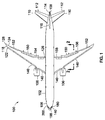
- the aircraft 100 may include a fuselage 102 having a pair of wings 118 attached to the fuselage 102 at a wing root 126 and extending outwardly toward a wing tip 128.
- One or more propulsion units 106 may be mounted on the wings 118.
- the aircraft 100 may include an empennage 108 having a horizontal tail 110 and elevator 112, and a vertical tail 114 and rudder 116 for directional control of the aircraft 100.
- the aircraft 100 may include one or more leading edge devices 140 mounted on the leading edge 122 of the wings 118, and one or more trailing edge devices 150 mounted on the trailing edge 124 of the wings 118.
- the leading edge devices 140 and trailing edge devices 150 may be moved from a retracted position 146, 166 ( Figure 2 ) to one or more deployed positions 148, 168 ( Figure 3 ) to improve the lift characteristics and/or drag characteristics of the wings 118.
- the aircraft 100 advantageously includes a flap optimizing system 180 for optimizing the position of one or more trailing edge devices 150 as a function of aircraft data 400 ( Figure 4 ) as described below.
- the flap optimizing system 180 is described in the context of a tube-and-wing aircraft 100 shown in Figure 1 , the flap optimizing system 180 may be incorporated into any aircraft embodiment, without limitation, including blended wing aircraft, hybrid wing-body aircraft, and other aircraft embodiments.
- FIG. 2 shown is a cross-section of a wing 118 illustrating an embodiment of a leading edge device 140 in the form of a slat 142 positioned in a neutral or retracted position 146 and illustrating a trailing edge device 150 in the form of a flap 158 in a retracted position 166.
- the wing 118 may include a spoiler 156 partially overlapping the flap 158.
- the slat 142 When deployed, the slat 142 may be extended forwardly and downwardly as shown in Figure 3 .
- the slat 142 may be coupled to a torque tube (not shown) which may be driven by a power drive unit (not shown) for actuating the slat 142.
- leading edge device 140 may be provided in any one of a variety of different leading edge device 140 embodiments.
- the leading edge device 140 may be configured as a Krueger flap, or in other leading edge device embodiments.
- the trailing edge device 150 is shown as a simple flap 158 supported on a drop hinge 160 and which may be actuated to an optimum flap setting 184 ( Figure 3 ) using the flap optimizing system 180 ( Figure 4 ) disclosed herein.
- the flap chord line 164 may be aligned with the wing chord line 120 which may pass through the trailing edge of the flap 158.
- the flap 158 may be provided in alternative embodiments wherein the flap chord line 164 is not aligned with the wing chord line 120 when the flap 158 is in a retracted position 166.
- trailing edge device 150 is shown as a simple flap 158, the trailing edge device 150 may be provided in any one of a variety of different configurations, and is not limited to the drop hinge 160 flap 158 embodiment.
- the trailing edge devices 150 may be configured as plain flaps, single-slotted flaps, multi-slotted Fowler flaps, or any one of a variety of other trailing edge device 150 configurations that may be actuated in conjunction with the flap optimizing system 180 disclosed herein.
- the flap optimizing system 180 may be configured to optimize the position of other trailing edge devices 150 such as flaperons 154 ( Figure 1 ), ailerons 152 ( Figure 1 ), and other trailing edge devices 150, and is not limited to optimizing the position of a flap 158.
- FIG. 3 shown is a cross-section of a wing 118 illustrating the leading edge slat 142 and the trailing edge flap 158 in a deployed position 148, 168.
- the flap 158 may be actuated by the flap actuation system 174 in response to selection of a flap setting using a flap optimizing system 180 ( Figure 4 ) disclosed herein.
- the flap actuation system 174 may include a trailing edge linkage assembly (not shown) that may be coupled to a torque tube (not shown).
- the torque tube may be rotatably driven by a centrally-located power drive unit (not shown) and/or by a local dedicated actuator (not shown).
- Actuation of the flaps 158 may be performed by actuator control electronics (not shown) which may operate in conjunction with a flight control computer 182 ( Figure 4 ). As described in greater detail below, in an embodiment, the flaps 158 may be actuated in response to a command issued by the pilot using a variable-trailing-edge-position switch 216 ( Figure 4 ) of a flap control system 198.
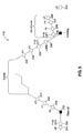
- FIG. 4 shown is a diagrammatic illustration of a flap optimizing system 180 including a processor-based flight control computer 182 as may be implemented for determining the optimum flap setting 184 ( Figure 3 ).
- the flight control computer 182 may compute the optimum flap setting 184 and a corresponding optimum thrust setting 220 ( Figure 7 ) based on aircraft data 400 which may include airport parameters and/or airport atmospheric data.
- the flap optimizing system 180 may include a flap control device 200 which may provide a means for adjusting the flaps 158 to any one of a variety of different flap deflection angles (i.e., flap settings).
- the flaps 158 may be positioned to one of a plurality of discrete flap settings within a flap setting range 212 ( Figure 3 ).
- the flap optimizing system 180 advantageously includes the variable-trailing-edge-position switch 216 which may allow a pilot to select a desired flap setting 186 which may correspond to the optimum flap setting 184 ( Figure 3 ) as determined by the flight control computer 182.
- the optimum flap setting 184 or the desired flap setting 186 may satisfy takeoff performance requirements for the aircraft 100 such as requirements for takeoff distance, minimum unstick speed, tail-clearance, climb gradient, obstacle clearance, and other requirements.
- the aircraft data 400 may include aircraft gross weight, aircraft center of gravity, maximum takeoff thrust generated by the propulsion units 106 ( Figure 1 ), and/or other aircraft data 400 reflecting the state of the aircraft 100.
- Aircraft data 400 may also include airport parameters and airport atmospheric data.
- Airport parameters may include data that is generally static or non-changing regarding an airport. For example, airport parameters may include the runway length and runway gradient, the location of any obstacles (not shown) relative to the runway, local terrain, and other static parameters associated with the airport. Airport parameters may further include rolling resistance of the runway surface which may affect the acceleration of the aircraft during takeoff. For example, a paved and smooth runway may provide less rolling friction and allow faster acceleration for the aircraft 100 than a gravel runway or grass runway.
- airport parameters may include the current runway condition such as whether the runway is dry or damp, or contaminated with standing water, snow, slush, or other debris which may increase rolling friction and/or retard acceleration of the aircraft 100.
- Airport parameters may further include the airport elevation which may affect the density altitude or pressure altitude which may have a direct bearing on the aerodynamics and engine performance of the aircraft 100.
- the aircraft data 400 may include airport atmospheric data representing meteorological conditions at the airport and/or near the airport, such as along the aircraft departure route during the climb-out phase when the aircraft 100 is departing the runway.
- airport atmospheric data may include outside air temperature as may be measured at a control tower of the airport or at other locations at or near the airport. The outside air temperature may affect the above-mentioned density altitude and pressure altitude.
- Airport atmospheric data may further include the wind direction as may be indicated by a windsock or other wind-measuring device.
- Airport atmospheric data may also include wind speed, wind gust information, and other atmospheric data.
- the aircraft data 400 may be pre-loaded into the flight control computer 182 and/or entered into the flight control computer 182 by a pilot or other flight crew member or other personnel.
- the flight control computer 182 may be located remotely from the aircraft 100.
- an airline dispatcher may load aircraft data 400 and/or airport information into a remote flight control computer 182 which may determine the optimum flap setting 184 and/or optimum thrust setting 220.
- the airline dispatcher may transmit the optimum flap setting 184 and other flight plan data to the flight crew on the flight deck.
- the flight crew may retrieve the optimum flap setting 184 by contacting the airline dispatcher or other personnel prior to takeoff.
- the optimum flap setting 184 and/or optimum thrust setting 220 may be transmitted to the flight crew verbally and/or by data transmission such as by internet connection to a local area network of the airport, by other wireless means, and/or by hardwired means.
- the flight control computer 182 may be located onboard the aircraft 100.
- the flight control computer 182 may be integrated into the avionics (not shown) or into a flight control system (not shown) on the flight deck.
- Aircraft data 400 may be entered into the flight control computer 182 by the pilot or other flight crew.
- the flight control computer 182 may be included in a portable computing device that may be carried onboard the aircraft 100 such as by the flight crew. The aircraft data 400 may be entered into the portable computing device at any time prior to departure to determine the optimum flap setting 184.
- the flight control computer 182 may receive updated or real-time airport atmospheric data such as outside air temperature, wind direction, wind speed, runway conditions, and other data prior to departure to compute an updated optimum flap setting 184 and/or optimum thrust setting 220 for takeoff.
- the flap control device 200 may be included with or integrated into a flight control system (not shown) of the aircraft 100.
- the flap control device 200 may be mounted on a console or control stand on the flight deck.
- the flap control device 200 may include a plurality of control device positions 206 corresponding to flap settings.
- the flap control device 200 may be configured as a flap control lever 202 or handle that may be movable along a forward-and-aft direction between one or more flap lever positions 208.
- the flap control device 200 may be provided in any embodiment for manipulating the flaps 158, and is not limited to a flap control lever 202.
- the flap control device 200 may have a plurality of flap lever positions 208 and may optionally include one or more mechanical gates 204 configured to prevent movement of the flap control lever 202 until the flap control lever 202 is lifted, depressed, or otherwise manipulated to move the flap control lever 202 past the mechanical gate 204.
- the gates 204 at the F1 and F20 detents may prevent inadvertent retraction of the flaps 158 past such flap settings.
- Each one of the flap lever positions 208 may correspond to a flap setting or flap setting range 212.
- one of the flap lever positions 208 may correlate to a flap setting range 212 associated with a takeoff flaps position 234 (F15/OPT) for placing the aircraft 100 in a takeoff configuration 232 ( Figures 3 and 5 ).
- flap lever positions 208 may include an up flaps position 244 (UP) corresponding to a cruise configuration ( Figure 5 ) of the aircraft 100, a hold flaps configuration 242 (F1) corresponding to a hold configuration of the aircraft 100, an approach flaps position 238 (F5) corresponding to an approach configuration of the aircraft 100, a go-around flaps position 236 (F15/OPT) corresponding to a go-around configuration of the aircraft 100, a landing flaps position 240 (LAND) corresponding to a landing configuration of the aircraft 100, and other flap lever positions corresponding to other aircraft configurations (not shown).
- UP up flaps position 244
- F1 hold flaps configuration
- approach flaps position 238 F5
- a go-around flaps position 236 F15/OPT
- LAND landing flaps position 240
- the flap lever positions 208 may be identified by one or more alphanumeric characters such as single digit whole numbers and/or by alpha characters. As indicated above, the flap lever positions 208 may be identified by flap settings UP, F1, F5, F15/OPT, F20, LAND, and which may or may not correspond to the actual flap angles 170 of the flaps 158. For example, on certain aircraft 100, a flap setting of F5 may correspond to an actual flap angle of 12 degrees, or some other actual flap angle.
- the flap lever position 208 on certain aircraft 100 may be identified by single digit whole numbers, such as 0, 1, 2, 3/OPT, FULL, and which may correspond to respective actual flap angles of 0, 17, 22, 23-31, and 32 degrees, or to another set of respective actual flap angles.
- the flap lever position 208 of 3/OPT may comprise the flap lever position 208 for which the variable-trailing-edge-position switch 216 is operative, and may thereby allow for manual selection, in a predetermined flap deflection increment 172 ( Figure 3 ), of an actual flap angle 170 ( Figure 3 ) of between and including approximately 23-31 degrees.
- the flap lever position F15/OPT may be a designated flap lever position 210 for which the variable-trailing-edge-position switch 216 is operative, and thereby allowing for manual (e.g., pilot) selection of a desired flap setting 186.
- the variable-trailing-edge-position switch 216 may be non-operative when the flap control lever 202 is in a non-designated flap lever position 214.
- the variable-trailing-edge-position switch 216 may be configured to position the flaps 158 within a flap setting range 212 provided by the designated flap lever position 210.
- variable-trailing-edge-position switch 216 may be limited to selecting a flap setting of between approximately 5-20 degrees, or some other flap setting range.
- the pilot may use the variable-trailing-edge-position switch 216 to select a desired flap setting 186 that may be slightly different than the optimum flap setting 184 computed by the flight control computer 182.
- the flap actuation system 174 may be commanded to position the flaps 158 at the flap setting corresponding to the F18 switch position.
- variable-trailing-edge-position switch 216 is described in the context of adjusting the flap setting when the flap control lever 202 is in a single designated flap lever position 210 such as a takeoff flaps position 234 (e.g., F15/OPT), the flap control system 198 may be provided in an embodiment wherein the variable-trailing-edge-position switch 216 is operative in more than one designated flap lever position 210.
- the switch may be operative to adjust the flap setting in flap deflection increments 172 ( Figure 3 ) of a predetermined minimum amount whenever the flap control lever 202 is in any one of a number of different designated flap lever positions 210.
- the switch may be operative when the flap lever position 208 is in the F15/OPT position (e.g., takeoff flaps position 234), and may also be operative when the flap lever position 208 is in the LAND position (e.g., landing flaps position 240).
- the flap lever position 208 is in the F15/OPT position (e.g., takeoff flaps position 234), and may also be operative when the flap lever position 208 is in the LAND position (e.g., landing flaps position 240).
- variable-trailing-edge-position switch 216 may be located near the flap control lever 202. Although shown as a rotary dial, the variable-trailing-edge-position switch 216 may be configured as a push-button mechanism, as a mechanical slider, or in any one of a variety of other switch embodiments.
- the variable-trailing-edge-position switch 216 may include a plurality of the switch positions 218. In an embodiment, the variable-trailing-edge-position switch 216 may comprise a detented switch with discrete contacts and/or mechanical stops at each switch position 218. The detents of the variable-trailing-edge-position switch 216 may be configured to prevent inadvertent actuation of the variable-trailing-edge-position switch 216.
- variable-trailing-edge-position switch 216 may be configured to be non-movable unless commanded by positive action from the flight crew. Furthermore, the variable-trailing-edge-position switch 216 may also be configured to protect against inadvertent actuation. For example, the variable-trailing-edge-position switch 216 may require depressing the variable-trailing-edge-position switch 216, or pulling up on the variable-trailing-edge-position switch 216 before the switch can be moved or rotated. In addition, the variable-trailing-edge-position switch 216 may be configured such that flap extension and flap retraction are commanded by moving the variable-trailing-edge-position switch 216 in mutually exclusive directions.
- the optimum flap setting 184 may be digitally selected in a software program implemented in a flight control system (not shown) of the aircraft. For example, after the flight control computer 182 determines the optimum flap setting 184, the optimum flap setting 184 may be digitally entered into a flight management computer (not shown) or other system for automatically commanding the flap actuation system 174 to move the flaps 158 to the optimum flap setting 184.
- Such an arrangement may provide for pilot override of the optimum flap setting 184, or allow the pilot to adjust the optimum flap setting 184 to a desired flap setting 186 that may be slightly different than the optimum flap setting 184 using the variable-trailing-edge-position switch 216.
- variable-trailing-edge-position switch 216 may be configured to change the desired flap setting 186 such that the flaps are adjusted in flap deflection increments 172 ( Figure 3 ) of no greater than approximately one degree of actual flap angle 170 ( Figure 3 ). However, the variable-trailing-edge-position switch 216 may be configured to adjust the flaps 158 in flap deflection increments 172 of greater than one degree of actual flap angle 170.
- the actual flap angle 170 may be defined as the angle between the local wing chord line 120 ( Figure 3 ) and the local flap chord line 164 ( Figure 3 ), as described above, wherein the local flap chord line 164 may be aligned with the local wing chord line 120 when the flap 158 is in a retracted position 166 ( Figure 3 ).
- the actual flap angle 170 may be measured by different means. For example, for a multi-slotted flap (not shown) having an intermediate flap element (not shown) and an aft flap element (not shown), the flap angle may be measured between a local flap chord line of the intermediate flap element and the local wing chord line.
- the difference between two adjacent switch positions 218 on the variable-trailing-edge-position switch 216 may correspond to a flap deflection increment 172 for adjusting the position of the flaps 158 ( Figure 3 ).
- moving the variable-trailing-edge-position switch 216 from switch position F17 to switch position F18 may move the flaps 158 by a flap deflection increment 172 of approximately one degree of actual flap angle.
- moving the variable-trailing-edge-position switch 216 between two (2) adjacent switch positions 218 may move the flaps 158 in flap deflection increments 172 of less than or greater than approximately one degree of actual flap angle.
- variable-trailing-edge-position switch 216 may be configured such that the switch positions 218 allow for moving the flaps 158 at non-uniform flap deflection increments 172.
- the flap deflection increment 172 may be relatively small (e.g., a one-degree flap deflection increment) when the flap lever position 208 is in a shallow flap setting such as the F5 position (e.g., the approach flaps position 238).
- the flap deflection increment 172 may be larger (e.g., a two-degree flap deflection increment) when the flap lever position 208 is in a deeper flap setting such as the LAND position (e.g., the landing flaps position 240).
- variable-trailing-edge-position switch 216 is shown in Figure 4 having switch positions (e.g., F16, F17, F18, etc.) arranged in a circular pattern around the perimeter of the variable-trailing-edge-position switch 216, the variable-trailing-edge-position switch 216 may instead be provided with a digital display window (not shown) for digitally displaying the optimum flap setting 184 computed by the flight control computer, or digitally displaying the desired flap setting 186 which may be manually selected by the pilot using the variable-trailing-edge-position switch 216.
- switch positions e.g., F16, F17, F18, etc.
- the variable-trailing-edge-position switch 216 may instead be provided with a digital display window (not shown) for digitally displaying the optimum flap setting 184 computed by the flight control computer, or digitally displaying the desired flap setting 186 which may be manually selected by the pilot using the variable-trailing-edge-position switch 216.
- the flap optimizing system may be configured such that when the flap lever position 208 is in a shallow flap setting such as the F5 position, the digital display window (not shown) displays relatively small flap deflection increments (e.g., one degree increments such as 16, 17, 18, etc.) as may be adjusted by the pilot using the variable-trailing-edge-position switch 216, and when the flap lever position 208 is in a deeper flap setting such as the LAND position, the digital display window displays larger flap deflection increments (e.g., two-degree increments) as may be adjusted by the pilot using the variable-trailing-edge-position switch 216.
- relatively small flap deflection increments e.g., one degree increments such as 16, 17, 18, etc.
- the digital display window displays larger flap deflection increments (e.g., two-degree increments) as may be adjusted by the pilot using the variable-trailing-edge-position switch 216.
- Figure 5 shows a flight profile 412 of an aircraft 100 with different flap settings corresponding to different phases of a flight.
- the flap control system 198 may be configured such that the variable-trailing-edge-position switch 216 may be used to fine tune the flap setting within the range of flap deflection angles provided by the designated flap lever position 210.
- variable-trailing-edge-position switch 216 is not limited to adjusting the flap setting prior to takeoff when the flap control lever 202 is in the takeoff flaps position 234 or the go-around flaps position 236 (F15/OPT), but may also be adjusted during one or more flight phases such as during a climb-out phase when the flap control lever 202 is in the approach flaps position 238 (F5), during a cruise phase when the flap control lever 202 is in the up flaps position 244 (UP), during a holding phase when the flap control lever 202 is in the hold flaps position 242 (F1), and during a landing phase when the flap control lever 202 is in the landing flaps position 240 (LAND).
- flight phases such as during a climb-out phase when the flap control lever 202 is in the approach flaps position 238 (F5), during a cruise phase when the flap control lever 202 is in the up flaps position 244 (UP), during a holding phase when the flap control lever 202 is in the hold flaps position 242 (F1)
- the method may include improving the takeoff performance of the aircraft 100 by optimizing a flap setting 184 ( Figure 4 ) of one or more flaps 158 ( Figure 1 ) or other trailing edge devices 150 ( Figure 1 ) for takeoff of the aircraft 100.
- the performance of the aircraft 100 may also be improved by computing an optimum thrust setting 220 of the propulsion units 106 in correspondence with the optimum flap setting 184.
- the optimum flap setting 184 may allow for a reduced thrust setting which may improve aircraft performance by reducing fuel burn resulting in a reduction in the amount of fuel required for a given mission. The reduction in fuel required may translate into increased payload capability of the aircraft 100.
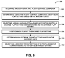
- Step 502 of the method 500 may include receiving aircraft data 400 ( Figure 4 ) at the flight control computer 182 ( Figure 4 ).
- the aircraft data 400 may be preloaded into the flight control computer 182 and/or manually entered into the flight control computer 182.
- static information such as airport parameters including airport elevation, runway length, runway gradient, and obstacle location and obstacle height may be preloaded into the flight control computer 182.
- Variable or changing airport parameters such as outside air temperature, barometric pressure, wind direction and speed, and/or runway conditions (e.g., wet, snow, slush, ice) may manually or automatically entered into the flight control computer 182 such as in real-time.
- aircraft data 400 such as aircraft takeoff weight, aircraft center of gravity, and/or other aircraft data that may affect takeoff performance may be entered into the flight control computer 182 after the aircraft is fueled and loaded with passengers, cargo, and other payload prior to takeoff.
- Step 504 of the method 500 of Figure 6 may include determining (e.g., calculating) the optimum flap setting 184 ( Figure 4 ) based on the aircraft data 400.
- the optimum flap setting 184 for takeoff may be determined by the flight control computer 182 based on aircraft data 400 ( Figure 4 ) such as runway length, aircraft gross weight, outside air temperature, and other data that may be received at the flight control computer 182.
- the flight control computer 182 may be located remotely from the aircraft 100 such as in an airline dispatch facility.
- An airline dispatcher may use the remote flight control computer 182 to compute the optimum flap setting 184 and may then transmit the optimum flap setting 184 to the flight crew by verbal transmission and/or by data transmission to the aircraft 100 such as to an onboard flight control system.
- the optimum flap setting 184 may be displayed on instrumentation (not shown) that is visible to the flight crew.
- the flight control computer 182 may comprise a portable computing device (e.g., a laptop computer) that may be carried onboard the aircraft 100 by the flight crew, or the flight control computer 182 may be fixedly installed with or integrated into a flight control system and/or other avionics on the flight deck, allowing the flight crew to compute the optimum flap setting 184 with the flight control computer 182 while onboard the aircraft 100.
- Step 506 of the method 500 of Figure 6 may include selecting a desired flap setting 186 corresponding to the optimum flap setting 184 ( Figure 4 ).
- the flight crew may manually select a control device position 206 ( Figure 4 ) on the flap control device 200 ( Figure 4 ).
- the flight crew may manually move the flap control lever 202 ( Figure 4 ) to a designated flap lever position 210 ( Figure 4 ) at which the variable-trailing-edge-position switch 216 ( Figure 4 ) is operative.
- the variable-trailing-edge-position switch 216 may be non-operative or ineffective when the flap control lever 202 is in a non-designated flap lever position 214 ( Figure 4 ).
- the flight crew may then select a switch position 218 on the variable-trailing-edge-position switch 216 after moving the flap control lever 202 to the designated flap lever position 210.
- the switch position 218 selected by the flight crew may represent a desired flap setting 186 desired by the flight crew which may be the same as the optimum flap setting 184 computed by the flight control computer or different than the optimum flap setting 184.
- the flight control computer 182 computes an optimum flap setting of F19 and the flight crew desires to select a slightly different flap setting (e.g., a desired flap setting 186) such as F18 ( Figure 4 )
- the flight crew may select F18 by rotating the variable-trailing-edge-position switch 216.
- the flight crew may adjust the flap setting to any value that is within the flap setting range 212 for a given designated flap lever position 210 as described above.
- the variable-trailing-edge-position switch 216 may be limited to selecting a flap setting of between approximately 5-20 degrees.
- variable-trailing-edge-position switch 216 may allow the flight crew to change the desired flap setting 186 in predetermined flap deflection increments 172 ( Figure 3 ).
- the variable-trailing-edge-position switch 216 may allow the flight crew to adjust the flap setting in flap deflection increments 172 of no greater than approximately one degree of actual flap angle 170 ( Figure 3 ).
- the flap deflection increment 172 may be greater than one degree of actual flap angle 170, or less than one degree of actual flap angle 170.
- Step 508 of the method 500 of Figure 6 may include positioning one or more flaps 158 at the desired flap setting 186 which may be the optimum flap setting 184 or slightly different than the optimum flap setting 184 as indicated above.
- the flap actuation system 174 may move the flaps 158 to the desired flap setting 186.
- the flight crew may adjust the variable-trailing-edge-position switch 216 to a switch position 218 corresponding to a desired flap setting 186.
- the flap actuation system 174 moves the flaps 158 to the desired flap setting 186.
- the flap actuation system 174 may position other trailing edge devices 150 at the desired flap setting 186 or optimum flap setting 184.
- the flap actuation system 174 may position trailing edge devices 150 such as flaperons 154 and/or ailerons 152 at the desired flap setting 186 or optimum flap setting 184.
- Such trailing edge devices 150 may be positioned separately or in conjunction with the positioning of the flaps 158.
- Step 510 of the method 500 of Figure 6 may include computing an optimum thrust setting 220 ( Figure 7 ) using the flight control computer 182 ( Figure 7 ) based on the aircraft data 400 ( Figure 7 ).
- the optimum thrust setting 220 may be computed in correspondence with the computing of the optimum flap setting 184 and may be based on aircraft data including airport parameters such a airport altitude and atmospheric data such as outside air temperature.
- the flight crew may adjust the thrust output of the propulsion units 106 ( Figure 7 ) to the optimum thrust setting 220 using the thrust levers 222 ( Figure 7 ).
- the flight crew may use the thrust levers 222 to adjust the thrust output of the propulsion units 106 to an optimum thrust setting 220 computed by the flight control computer 182, or to a desired thrust setting that may be slightly different than the optimum thrust setting 220.
- the optimum flap setting 184 may allow for an optimum thrust setting 220 that may correspond to a reduction in operational settings such thrust output (i.e., engine de-rate) for the propulsion units 106 during takeoff of the aircraft 100.
- the use of engine de-rate may reduce engine wear resulting in an increase in engine life and a reduction in engine maintenance and associated down time for the aircraft 100.
- a reduced thrust output associated with an optimum thrust setting 220 may also allow for the use of smaller engines and/or may result in reduced mission fuel burn, improved fuel efficiency for the aircraft 100, and a reduction in engine noise as perceived on the ground (i.e., community noise) during takeoff.
- the combination of the optimum thrust setting 220 and optimum flap setting 184 may provide improved aircraft performance such as improved climb performance of the aircraft during takeoff.
- the flight control computer 182 may compute an optimum flap setting 184 which may be a shallower flap angle than conventional flap settings available with conventional flap systems.
- a shallower flap angle of the optimum flap setting 184 may generate a reduced amount of aerodynamic drag for the aircraft 100 during takeoff which may result in an improved climb rate for the aircraft.
- the optimum flap setting 184 may result in an improvement in takeoff field length performance allowing for increased takeoff weight capability of the aircraft 100 where runway length is the limiting factor.
- FIG. 8 shown is a graph plotting takeoff field length 410 versus takeoff weight 402 for an aircraft 100 with standard flap settings 188 compared to the same aircraft 100 with optimum flap settings 184.
- a 500-foot reduction in takeoff field length may be realized by using the disclosed flap control system 198 to adjust the flaps 158 to an optimum flap setting of F18 relative to a longer takeoff field length 410 required for a standard flap setting of F15.
- mission payload capability may be maximized by implementing an optimum flap setting 184.
- a 9000 pound increase in takeoff weight may be realized by using the disclosed flap control system 198 to adjust the flaps to an optimum flap setting of F18 relative to a reduced takeoff weight available with a standard flap setting of F15.
- a system for optimizing performance of an aircraft comprising a flight control computer configured to compute an optimum flap setting based on aircraft data; a flap control system having a flap control device; and a flap actuation system coupled to the flap control system and being configured to position a trailing edge device at the optimum flap setting.
- the system disclosed wherein the flight control computer is configured to determine an optimum thrust setting based on the aircraft data.
- the flap control system further comprises a variable-trailing-edge-position switch that is operative to select a desired flap setting corresponding to the optimum flap setting, the variable-trailing-edge-position switch is operative when the flap control device is in a control device position.
- the flap control device comprises a flap control lever having a plurality of flap lever positions and at least one designated flap lever position at which the variable-trailing-edge-position switch is operative; and the variable-trailing-edge-position switch being non-operative when the flap control lever is in a non-designated flap lever position.
- the system disclosed wherein the designated flap lever position comprises at least one of the following: a takeoff flaps position, a go-around flaps position, an approach flaps position, and a landing flaps position.
- variable-trailing-edge-position switch is configured to change the desired flap setting such that the trailing edge device moves in flap deflection increments of no greater than approximately one degree of actual flap angle.
- aircraft data includes at least one member of a group consisting of aircraft gross weight, aircraft center of gravity, and maximum takeoff thrust.
- the aircraft data includes at least one member of a group consisting of airport atmospheric data and airport parameters; the airport atmospheric data including at least one of outside air temperature, airport elevation, density altitude, pressure altitude, wind speed, and wind direction; and the airport parameters including at least one of runway length, runway condition, and obstacle height.
- an aircraft comprising a wing having a trailing edge device mounted to a trailing edge; a system for optimizing a flap setting of the flap, comprising a processor-based flight control computer configured to compute an optimum flap setting based on aircraft data; a flap control system having a flap control device and a variable-trailing-edge-position switch for selecting a desired flap setting corresponding to the optimum flap setting, the variable-trailing-edge-position switch being operative when the flap control device is in a control device position; and a flap actuation system coupled to the flap control system and being configured to position the trailing edge device at the desired flap setting.
- the aircraft disclosed wherein the flight control computer is configured to determine an optimum thrust setting based on the aircraft data.
- a method of optimizing performance of an aircraft comprising determining an optimum flap setting based on aircraft data; selecting a desired flap setting corresponding to the optimum flap setting; and positioning a trailing edge device at the desired flap setting.
- the method disclosed further comprising: determining an optimum thrust setting based on the aircraft data.
- the method disclosed wherein the step of selecting the desired flap setting includes selecting a control device position on a flap control device.
- control device position comprises a flaps position at takeoff of the aircraft.
- step of selecting the desired flap setting further comprises selecting a switch position on a variable-trailing-edge-position switch, the switch position representing the desired flap setting.
- the method disclosed wherein the step of selecting the switch position comprise moving a flap control lever to a designated flap lever position at which the variable-trailing-edge-position switch is operative; and moving the switch position to the desired flap setting after positioning the flap control lever at the designated flap lever position.
- variable-trailing-edge-position switch is non-operative when the flap control lever is in a non-designated flap lever position.
- the method disclosed further comprising changing, using the variable-trailing-edge-position switch, the desired flap setting in a manner such that the trailing edge device moves in flap deflection increments of no greater than approximately one degree of actual flap angle.
- the aircraft data includes at least one member of a group consisting of aircraft gross weight, and aircraft center of gravity.
- the aircraft data includes at least one member of a group consisting of outside air temperature, airport elevation, density altitude, pressure altitude, wind speed, wind direction, runway length, runway condition, and obstacle height.
Description
- The present disclosure relates generally to aircraft control surfaces and, more particularly, to optimizing a position of the trailing edge devices of an aircraft.
- Aircraft, such as commercial airliners, typically include control surfaces or devices mounted on the wings to improve the aerodynamic performance of the aircraft. Such control surfaces include wing leading edge devices and wing trailing edge devices which may be extended and/or deflected during different phases of a flight, to alter the lift and/or drag characteristics of the wings. For example, commercial airliners typically include trailing edge flaps which may be extended during takeoff to increase the camber of the wings, resulting in an increase in the lift characteristics of the wings during takeoff and climb-out of the aircraft.
- Conventional aircraft typically allow for extending the flaps to a limited number of flap settings for a given flight phase. Such flap settings may be based on the aircraft configuration and a given set of airport parameters and/or atmospheric conditions. For example, during takeoff, conventional aircraft may allow for extending the flaps to a takeoff flap setting of Flaps 15. Such a takeoff flap setting may be based on a maximum takeoff weight aircraft with engines operating at maximum takeoff thrust and departing from a standard length runway at sea level.
- However, the aircraft may have an actual takeoff weight that may be less than the maximum takeoff weight such that the Flaps 15 setting may result in operating the engines at an unnecessarily high thrust setting which may contribute to engine wear and generate excessive engine noise. In addition, positioning the flaps at a flap setting of Flaps 15 may generate a climb rate that is above or below what may be required for obstacle or engine-out climb requirements. In contrast, operating the engines at an optimum (e.g., reduced) thrust setting may allow for a reduction in engine sizing and reduced mission fuel burn corresponding to reduced fuel requirements which may translate into improved aircraft performance in the form of increased takeoff weight capability.
- As can be seen, there exists a need in the art for a system and method for optimizing the flap setting and thrust setting for a given aircraft configuration and a given set of airport parameters and/or atmospheric conditions.
-
US 2012/0032030 A1 discloses a high-lift system of an aeroplane including one or more high-lift flaps, an activation device with an activation function for generating adjustment commands for adjusting the adjustment state of the high-lift flaps, and a drive device coupled with the high-lift flaps, which is configured such that on the basis of activation commands the high-lift flaps are adjusted between a retracted adjustment state and an extended adjustment state. The activation function, on the basis of input value, generates adjustment commands and transmits these to the drive device for adjusting the high-lift flaps. -
US 4,106,730 discloses a control system for automatically activating the flight control surfaces of a STOL aircraft that utilizes upper surface blown flaps when the aircraft executes a STOL landing or takeoff maneuver with one engine inoperative in that the engine does not provide the desired or scheduled amount of thrust. The system monitors internal engine pressure of each engine to detect such engine failure and deploys the upper surface blown flaps, conventional flaps and spoilers used as direct lift control devices to provide a relatively uniform lift distribution across the aircraft wing and hence lower induced drag. -
US 2010/0200704 A1 discloses a device for automatically controlling a system of high-lift elements of an aircraft, which high-lift elements can be set to a retracted and to several extended configurations for cruising, holding flight, takeoff or landing; comprising a flap control unit that by way of a control connection is connected, so as to be functionally effective, to a drive system of the high-lift elements; and an operating unit, connected to the flap control unit, for entering operating instructions that influence the setting of the high-lift elements, where the flap control unit is provided for calculating switching speeds that are associated with the respective configurations of the high-lift elements, depending on flight state data and further flight-operation-relevant data; and where, in addition, the flap control unit can also automatically carry out switchover of the operating modes for takeoff or for the landing approach and is provided to automatically generate the instructions that instruct the configuration change, depending on the flight speed. -
US 2012/0153085 A1 discloses an aircraft wing system for differentially adjusting a first deployable lift device and a second deployable lift device on a wing during take-off and landing. The system has a controller, which is programmed to determine desired positions for said first and second deployable lift devices, based on a desired position signal, and to activate high and low horsepower motors to move said first deployable lift devices to desired positions. -
US 4,821,981 discloses a system for enhancing the performance of an aircraft during flight. The aircraft, which includes at least two control surfaces, such as stabilon and trailing edge flaps, includes devices for: generating a signal representative of the optimum normal acceleration from signals representative of the aircraft's flight status, generating a signal representative of the aircraft's actual normal acceleration, comparing the optimum signal to the actual signal, and generating a command to alter the position of either one or both of the aircraft's control surfaces to reduce any differences between the optimum and actual normal acceleration signals. -
EP 0193442 discloses automatic camber control, in which wind tunnel data for a three control surface aircraft (10) is developed for lift, pitching moment, and drag coefficient characteristics. This data is then input into a Lagrange optimization program to determine a unique combination of canard, flap, (18) and strake flap (20) positions that trim the pitching moment coefficient to zero and provide the minimum drag coefficient as a function of lift coefficient and/or angle of attack, Mach number, and altitude. The outputs from the Lagrange optimization program are then tabulated and loaded into the memory of a digital flight control computer (34) of an aircraft. By means of the computer, the position of the control surfaces are changed to the predetermined settings of the look-up table for minimum drag. - In a first aspect of the invention there is provided a system for optimizing performance of an aircraft as defined in claim 1 of the appended claims. In a second aspect there is provided a method as defined in
claim 7. - The above-noted needs associated with flap settings and thrust settings are specifically addressed and alleviated by the present disclosure which provides a system for optimizing performance of an aircraft. The system may include a flight control computer configured to compute an optimum flap setting based on aircraft data. The system may further include a flap control system having a flap control device, and a flap actuation system coupled to the flap control system for positioning a trailing edge device at the optimum flap setting.
- In a further embodiment, disclosed is an aircraft having a wing. The wing may include a trailing edge device mounted to a trailing edge. The aircraft may also include a system for optimizing a flap setting of the flap. The system may include a processor-based flight control computer configured to compute an optimum flap setting based on aircraft data. The system may further include a flap control system having a flap control device and a variable-trailing-edge-position switch for selecting a desired flap setting corresponding to the optimum flap setting. The variable-trailing-edge-position switch may be operative when the flap control device is in a control device position. The system may additionally include a flap actuation system coupled to the flap control system for positioning the trailing edge device at the desired flap setting.
- Also disclosed is a method of optimizing performance of an aircraft. The method may include determining an optimum flap setting based on aircraft data. The method may additionally include selecting a desired flap setting corresponding to the optimum flap setting. The method may further include positioning a trailing edge device at the desired flap setting.
- The features, functions and advantages that have been discussed can be achieved independently in various embodiments of the present disclosure or may be combined in yet other embodiments, further details of which can be seen with reference to the following description and drawings below.
- These and other features of the present disclosure will become more apparent upon reference to the drawings wherein like numbers refer to like parts throughout and wherein:
-
Figure 1 is a is a top view of an aircraft; -
Figure 2 is a cross-sectional view of a wing taken along line 2 ofFigure 1 and showing a leading edge device and a trailing edge device in a retracted position; -
Figure 3 is a cross-sectional view of the wing ofFigure 2 and showing the leading edge device and the trailing edge device in a deployed position; -
Figure 4 is a diagrammatic view of a system for determining an optimum flap setting, and further showing a flap control device having a variable-trailing-edge-position switch for selecting a desired flap setting corresponding to the optimum flap setting; -
Figure 5 is an embodiment of a flight profile of an aircraft showing different flap settings corresponding to different flight phases of the aircraft; -
Figure 6 is a flowchart illustrating one or more operations that may be included in a method of optimizing a flap setting and a thrust setting of an aircraft; -
Figure 7 is a block diagram of an implementation of a flap optimizing system for determining an optimum flap setting and a thrust setting based on aircraft data and/or airport information; and -
Figure 8 is a graph plotting takeoff field length versus takeoff weight and illustrating the increase in aircraft performance as a result of optimum flap settings. - Referring now to the drawings wherein the showings are for purposes of illustrating various embodiments of the present disclosure, shown in
Figure 1 is a perspective view of anaircraft 100. Theaircraft 100 may include afuselage 102 having a pair ofwings 118 attached to thefuselage 102 at awing root 126 and extending outwardly toward awing tip 128. One ormore propulsion units 106 may be mounted on thewings 118. Theaircraft 100 may include anempennage 108 having ahorizontal tail 110 andelevator 112, and avertical tail 114 andrudder 116 for directional control of theaircraft 100. Theaircraft 100 may include one or more leadingedge devices 140 mounted on the leadingedge 122 of thewings 118, and one or moretrailing edge devices 150 mounted on thetrailing edge 124 of thewings 118. - In
Figure 1 , the leadingedge devices 140 andtrailing edge devices 150 may be moved from a retracted position 146, 166 (Figure 2 ) to one or more deployed positions 148, 168 (Figure 3 ) to improve the lift characteristics and/or drag characteristics of thewings 118. Theaircraft 100 advantageously includes aflap optimizing system 180 for optimizing the position of one or moretrailing edge devices 150 as a function of aircraft data 400 (Figure 4 ) as described below. Although theflap optimizing system 180 is described in the context of a tube-and-wing aircraft 100 shown inFigure 1 , theflap optimizing system 180 may be incorporated into any aircraft embodiment, without limitation, including blended wing aircraft, hybrid wing-body aircraft, and other aircraft embodiments. - Referring to
Figure 2 , shown is a cross-section of awing 118 illustrating an embodiment of a leadingedge device 140 in the form of aslat 142 positioned in a neutral or retracted position 146 and illustrating atrailing edge device 150 in the form of aflap 158 in a retractedposition 166. Thewing 118 may include aspoiler 156 partially overlapping theflap 158. When deployed, theslat 142 may be extended forwardly and downwardly as shown inFigure 3 . In an embodiment, theslat 142 may be coupled to a torque tube (not shown) which may be driven by a power drive unit (not shown) for actuating theslat 142. Although shown as aslat 142, theleading edge device 140 may be provided in any one of a variety of differentleading edge device 140 embodiments. For example, theleading edge device 140 may be configured as a Krueger flap, or in other leading edge device embodiments. - In
Figure 2 , the trailingedge device 150 is shown as asimple flap 158 supported on adrop hinge 160 and which may be actuated to an optimum flap setting 184 (Figure 3 ) using the flap optimizing system 180 (Figure 4 ) disclosed herein. In the present disclosure, when theflap 158 is in a retractedposition 166 as shown inFigure 2 , theflap chord line 164 may be aligned with thewing chord line 120 which may pass through the trailing edge of theflap 158. However, theflap 158 may be provided in alternative embodiments wherein theflap chord line 164 is not aligned with thewing chord line 120 when theflap 158 is in a retractedposition 166. Although the trailingedge device 150 is shown as asimple flap 158, the trailingedge device 150 may be provided in any one of a variety of different configurations, and is not limited to thedrop hinge 160flap 158 embodiment. For example, the trailingedge devices 150 may be configured as plain flaps, single-slotted flaps, multi-slotted Fowler flaps, or any one of a variety of other trailingedge device 150 configurations that may be actuated in conjunction with theflap optimizing system 180 disclosed herein. In this regard, although theflap optimizing system 180 is described in the context of optimizing the position of aflap 158, theflap optimizing system 180 may be configured to optimize the position of other trailingedge devices 150 such as flaperons 154 (Figure 1 ), ailerons 152 (Figure 1 ), and other trailingedge devices 150, and is not limited to optimizing the position of aflap 158. - Referring to
Figure 3 , shown is a cross-section of awing 118 illustrating theleading edge slat 142 and the trailingedge flap 158 in a deployedposition 148, 168. Theflap 158 may be actuated by theflap actuation system 174 in response to selection of a flap setting using a flap optimizing system 180 (Figure 4 ) disclosed herein. In an embodiment, theflap actuation system 174 may include a trailing edge linkage assembly (not shown) that may be coupled to a torque tube (not shown). The torque tube may be rotatably driven by a centrally-located power drive unit (not shown) and/or by a local dedicated actuator (not shown). Actuation of theflaps 158 may be performed by actuator control electronics (not shown) which may operate in conjunction with a flight control computer 182 (Figure 4 ). As described in greater detail below, in an embodiment, theflaps 158 may be actuated in response to a command issued by the pilot using a variable-trailing-edge-position switch 216 (Figure 4 ) of aflap control system 198. - Referring to
Figure 4 , shown is a diagrammatic illustration of aflap optimizing system 180 including a processor-basedflight control computer 182 as may be implemented for determining the optimum flap setting 184 (Figure 3 ). Theflight control computer 182 may compute the optimum flap setting 184 and a corresponding optimum thrust setting 220 (Figure 7 ) based onaircraft data 400 which may include airport parameters and/or airport atmospheric data. Theflap optimizing system 180 may include aflap control device 200 which may provide a means for adjusting theflaps 158 to any one of a variety of different flap deflection angles (i.e., flap settings). Theflaps 158 may be positioned to one of a plurality of discrete flap settings within a flap setting range 212 (Figure 3 ). Theflap optimizing system 180 advantageously includes the variable-trailing-edge-position switch 216 which may allow a pilot to select a desired flap setting 186 which may correspond to the optimum flap setting 184 (Figure 3 ) as determined by theflight control computer 182. The optimum flap setting 184 or the desired flap setting 186 may satisfy takeoff performance requirements for theaircraft 100 such as requirements for takeoff distance, minimum unstick speed, tail-clearance, climb gradient, obstacle clearance, and other requirements. - In
Figure 4 , theaircraft data 400 may include aircraft gross weight, aircraft center of gravity, maximum takeoff thrust generated by the propulsion units 106 (Figure 1 ), and/orother aircraft data 400 reflecting the state of theaircraft 100.Aircraft data 400 may also include airport parameters and airport atmospheric data. Airport parameters may include data that is generally static or non-changing regarding an airport. For example, airport parameters may include the runway length and runway gradient, the location of any obstacles (not shown) relative to the runway, local terrain, and other static parameters associated with the airport. Airport parameters may further include rolling resistance of the runway surface which may affect the acceleration of the aircraft during takeoff. For example, a paved and smooth runway may provide less rolling friction and allow faster acceleration for theaircraft 100 than a gravel runway or grass runway. In addition, airport parameters may include the current runway condition such as whether the runway is dry or damp, or contaminated with standing water, snow, slush, or other debris which may increase rolling friction and/or retard acceleration of theaircraft 100. Airport parameters may further include the airport elevation which may affect the density altitude or pressure altitude which may have a direct bearing on the aerodynamics and engine performance of theaircraft 100. - The
aircraft data 400 may include airport atmospheric data representing meteorological conditions at the airport and/or near the airport, such as along the aircraft departure route during the climb-out phase when theaircraft 100 is departing the runway. Such airport atmospheric data may include outside air temperature as may be measured at a control tower of the airport or at other locations at or near the airport. The outside air temperature may affect the above-mentioned density altitude and pressure altitude. Airport atmospheric data may further include the wind direction as may be indicated by a windsock or other wind-measuring device. Airport atmospheric data may also include wind speed, wind gust information, and other atmospheric data. Theaircraft data 400 may be pre-loaded into theflight control computer 182 and/or entered into theflight control computer 182 by a pilot or other flight crew member or other personnel. - In
Figure 4 , theflight control computer 182 may be located remotely from theaircraft 100. For example, in the process of developing a flight plan, an airline dispatcher may loadaircraft data 400 and/or airport information into a remoteflight control computer 182 which may determine the optimum flap setting 184 and/or optimum thrust setting 220. Prior to departure, the airline dispatcher may transmit the optimum flap setting 184 and other flight plan data to the flight crew on the flight deck. Alternatively, the flight crew may retrieve the optimum flap setting 184 by contacting the airline dispatcher or other personnel prior to takeoff. The optimum flap setting 184 and/or optimum thrust setting 220 may be transmitted to the flight crew verbally and/or by data transmission such as by internet connection to a local area network of the airport, by other wireless means, and/or by hardwired means. - In a further embodiment, the
flight control computer 182 may be located onboard theaircraft 100. For example, theflight control computer 182 may be integrated into the avionics (not shown) or into a flight control system (not shown) on the flight deck.Aircraft data 400 may be entered into theflight control computer 182 by the pilot or other flight crew. In another embodiment theflight control computer 182 may be included in a portable computing device that may be carried onboard theaircraft 100 such as by the flight crew. Theaircraft data 400 may be entered into the portable computing device at any time prior to departure to determine the optimum flap setting 184. In an embodiment, theflight control computer 182 may receive updated or real-time airport atmospheric data such as outside air temperature, wind direction, wind speed, runway conditions, and other data prior to departure to compute an updated optimum flap setting 184 and/or optimum thrust setting 220 for takeoff. - In
Figure 4 , theflap control device 200 may be included with or integrated into a flight control system (not shown) of theaircraft 100. For example, theflap control device 200 may be mounted on a console or control stand on the flight deck. Theflap control device 200 may include a plurality ofcontrol device positions 206 corresponding to flap settings. In an embodiment, theflap control device 200 may be configured as aflap control lever 202 or handle that may be movable along a forward-and-aft direction between one or more flap lever positions 208. However, theflap control device 200 may be provided in any embodiment for manipulating theflaps 158, and is not limited to aflap control lever 202. Theflap control device 200 may have a plurality offlap lever positions 208 and may optionally include one or moremechanical gates 204 configured to prevent movement of theflap control lever 202 until theflap control lever 202 is lifted, depressed, or otherwise manipulated to move theflap control lever 202 past themechanical gate 204. For example, thegates 204 at the F1 and F20 detents may prevent inadvertent retraction of theflaps 158 past such flap settings. - Each one of the flap lever positions 208 may correspond to a flap setting or
flap setting range 212. For example, one of the flap lever positions 208 may correlate to aflap setting range 212 associated with a takeoff flaps position 234 (F15/OPT) for placing theaircraft 100 in a takeoff configuration 232 (Figures 3 and5 ). Other flap lever positions 208 may include an up flaps position 244 (UP) corresponding to a cruise configuration (Figure 5 ) of theaircraft 100, a hold flaps configuration 242 (F1) corresponding to a hold configuration of theaircraft 100, an approach flaps position 238 (F5) corresponding to an approach configuration of theaircraft 100, a go-around flaps position 236 (F15/OPT) corresponding to a go-around configuration of theaircraft 100, a landing flaps position 240 (LAND) corresponding to a landing configuration of theaircraft 100, and other flap lever positions corresponding to other aircraft configurations (not shown). - In
Figure 4 , the flap lever positions 208 may be identified by one or more alphanumeric characters such as single digit whole numbers and/or by alpha characters. As indicated above, the flap lever positions 208 may be identified by flap settings UP, F1, F5, F15/OPT, F20, LAND, and which may or may not correspond to the actual flap angles 170 of theflaps 158. For example, oncertain aircraft 100, a flap setting of F5 may correspond to an actual flap angle of 12 degrees, or some other actual flap angle. In another embodiment not shown, theflap lever position 208 oncertain aircraft 100 may be identified by single digit whole numbers, such as 0, 1, 2, 3/OPT, FULL, and which may correspond to respective actual flap angles of 0, 17, 22, 23-31, and 32 degrees, or to another set of respective actual flap angles. Theflap lever position 208 of 3/OPT may comprise theflap lever position 208 for which the variable-trailing-edge-position switch 216 is operative, and may thereby allow for manual selection, in a predetermined flap deflection increment 172 (Figure 3 ), of an actual flap angle 170 (Figure 3 ) of between and including approximately 23-31 degrees. - For the
flap lever positions 208 identified by UP, F1, F5, F15/OPT, F20, LAND, the flap lever position F15/OPT may be a designatedflap lever position 210 for which the variable-trailing-edge-position switch 216 is operative, and thereby allowing for manual (e.g., pilot) selection of a desired flap setting 186. The variable-trailing-edge-position switch 216 may be non-operative when theflap control lever 202 is in a non-designatedflap lever position 214. The variable-trailing-edge-position switch 216 may be configured to position theflaps 158 within aflap setting range 212 provided by the designatedflap lever position 210. For example, when theflap control lever 202 is placed in the flap lever position F15/OPT, the variable-trailing-edge-position switch 216 may be limited to selecting a flap setting of between approximately 5-20 degrees, or some other flap setting range. The pilot may use the variable-trailing-edge-position switch 216 to select a desired flap setting 186 that may be slightly different than the optimum flap setting 184 computed by theflight control computer 182. For example, upon moving the variable-trailing-edge-position switch 216 to switch position F18, theflap actuation system 174 may be commanded to position theflaps 158 at the flap setting corresponding to the F18 switch position. - Although the variable-trailing-edge-
position switch 216 is described in the context of adjusting the flap setting when theflap control lever 202 is in a single designatedflap lever position 210 such as a takeoff flaps position 234 (e.g., F15/OPT), theflap control system 198 may be provided in an embodiment wherein the variable-trailing-edge-position switch 216 is operative in more than one designatedflap lever position 210. In this regard, the switch may be operative to adjust the flap setting in flap deflection increments 172 (Figure 3 ) of a predetermined minimum amount whenever theflap control lever 202 is in any one of a number of different designated flap lever positions 210. For example, the switch may be operative when theflap lever position 208 is in the F15/OPT position (e.g., takeoff flaps position 234), and may also be operative when theflap lever position 208 is in the LAND position (e.g., landing flaps position 240). - In
Figure 4 , the variable-trailing-edge-position switch 216 may be located near theflap control lever 202. Although shown as a rotary dial, the variable-trailing-edge-position switch 216 may be configured as a push-button mechanism, as a mechanical slider, or in any one of a variety of other switch embodiments. The variable-trailing-edge-position switch 216 may include a plurality of the switch positions 218. In an embodiment, the variable-trailing-edge-position switch 216 may comprise a detented switch with discrete contacts and/or mechanical stops at eachswitch position 218. The detents of the variable-trailing-edge-position switch 216 may be configured to prevent inadvertent actuation of the variable-trailing-edge-position switch 216. - In an embodiment, the variable-trailing-edge-
position switch 216 may be configured to be non-movable unless commanded by positive action from the flight crew. Furthermore, the variable-trailing-edge-position switch 216 may also be configured to protect against inadvertent actuation. For example, the variable-trailing-edge-position switch 216 may require depressing the variable-trailing-edge-position switch 216, or pulling up on the variable-trailing-edge-position switch 216 before the switch can be moved or rotated. In addition, the variable-trailing-edge-position switch 216 may be configured such that flap extension and flap retraction are commanded by moving the variable-trailing-edge-position switch 216 in mutually exclusive directions. - In a further embodiment, instead of mechanically selecting a desired flap setting 186 using the variable-trailing-edge-
position switch 216, the optimum flap setting 184 may be digitally selected in a software program implemented in a flight control system (not shown) of the aircraft. For example, after theflight control computer 182 determines the optimum flap setting 184, the optimum flap setting 184 may be digitally entered into a flight management computer (not shown) or other system for automatically commanding theflap actuation system 174 to move theflaps 158 to the optimum flap setting 184. By "automatic" or "automatically," it is meant in the context of the present application that the action (e.g., command, control, movement, deployment, extension, etc.) occurs or is performed without manual input (e.g., from the flight crew or other operator). In an embodiment, such an arrangement may provide for pilot override of the optimum flap setting 184, or allow the pilot to adjust the optimum flap setting 184 to a desired flap setting 186 that may be slightly different than the optimum flap setting 184 using the variable-trailing-edge-position switch 216. - In an embodiment, the variable-trailing-edge-
position switch 216 may be configured to change the desired flap setting 186 such that the flaps are adjusted in flap deflection increments 172 (Figure 3 ) of no greater than approximately one degree of actual flap angle 170 (Figure 3 ). However, the variable-trailing-edge-position switch 216 may be configured to adjust theflaps 158 inflap deflection increments 172 of greater than one degree ofactual flap angle 170. In embodiments wherein the flaps 158 (Figure 3 ) are configured assimple flaps 158, the actual flap angle 170 (Figure 3 ) may defined as the angle between the local wing chord line 120 (Figure 3 ) and the local flap chord line 164 (Figure 3 ), as described above, wherein the localflap chord line 164 may be aligned with the localwing chord line 120 when theflap 158 is in a retracted position 166 (Figure 3 ). However, for multi-slotted flaps or other non-simple flap configurations, theactual flap angle 170 may be measured by different means. For example, for a multi-slotted flap (not shown) having an intermediate flap element (not shown) and an aft flap element (not shown), the flap angle may be measured between a local flap chord line of the intermediate flap element and the local wing chord line. - In
Figure 4 , the difference between two adjacent switch positions 218 on the variable-trailing-edge-position switch 216 may correspond to aflap deflection increment 172 for adjusting the position of the flaps 158 (Figure 3 ). For example, moving the variable-trailing-edge-position switch 216 from switch position F17 to switch position F18 may move theflaps 158 by aflap deflection increment 172 of approximately one degree of actual flap angle. However, moving the variable-trailing-edge-position switch 216 between two (2)adjacent switch positions 218 may move theflaps 158 inflap deflection increments 172 of less than or greater than approximately one degree of actual flap angle. - In addition, the variable-trailing-edge-
position switch 216 may be configured such that the switch positions 218 allow for moving theflaps 158 at non-uniformflap deflection increments 172. For example, theflap deflection increment 172 may be relatively small (e.g., a one-degree flap deflection increment) when theflap lever position 208 is in a shallow flap setting such as the F5 position (e.g., the approach flaps position 238). Theflap deflection increment 172 may be larger (e.g., a two-degree flap deflection increment) when theflap lever position 208 is in a deeper flap setting such as the LAND position (e.g., the landing flaps position 240). Although the variable-trailing-edge-position switch 216 is shown inFigure 4 having switch positions (e.g., F16, F17, F18, etc.) arranged in a circular pattern around the perimeter of the variable-trailing-edge-position switch 216, the variable-trailing-edge-position switch 216 may instead be provided with a digital display window (not shown) for digitally displaying the optimum flap setting 184 computed by the flight control computer, or digitally displaying the desired flap setting 186 which may be manually selected by the pilot using the variable-trailing-edge-position switch 216. The flap optimizing system may be configured such that when theflap lever position 208 is in a shallow flap setting such as the F5 position, the digital display window (not shown) displays relatively small flap deflection increments (e.g., one degree increments such as 16, 17, 18, etc.) as may be adjusted by the pilot using the variable-trailing-edge-position switch 216, and when theflap lever position 208 is in a deeper flap setting such as the LAND position, the digital display window displays larger flap deflection increments (e.g., two-degree increments) as may be adjusted by the pilot using the variable-trailing-edge-position switch 216. -
Figure 5 shows aflight profile 412 of anaircraft 100 with different flap settings corresponding to different phases of a flight. During any one of the flight phases, theflap control system 198 may be configured such that the variable-trailing-edge-position switch 216 may be used to fine tune the flap setting within the range of flap deflection angles provided by the designatedflap lever position 210. In this regard, the variable-trailing-edge-position switch 216 is not limited to adjusting the flap setting prior to takeoff when theflap control lever 202 is in the takeoff flapsposition 234 or the go-around flaps position 236 (F15/OPT), but may also be adjusted during one or more flight phases such as during a climb-out phase when theflap control lever 202 is in the approach flaps position 238 (F5), during a cruise phase when theflap control lever 202 is in the up flaps position 244 (UP), during a holding phase when theflap control lever 202 is in the hold flaps position 242 (F1), and during a landing phase when theflap control lever 202 is in the landing flaps position 240 (LAND). - Referring to
Figure 6 with additional reference to the block diagram ofFigure 7 , shown is an embodiment of a method of optimizing the performance of anaircraft 100. In an embodiment, the method may include improving the takeoff performance of theaircraft 100 by optimizing a flap setting 184 (Figure 4 ) of one or more flaps 158 (Figure 1 ) or other trailing edge devices 150 (Figure 1 ) for takeoff of theaircraft 100. The performance of theaircraft 100 may also be improved by computing an optimum thrust setting 220 of thepropulsion units 106 in correspondence with the optimum flap setting 184. For example, the optimum flap setting 184 may allow for a reduced thrust setting which may improve aircraft performance by reducing fuel burn resulting in a reduction in the amount of fuel required for a given mission. The reduction in fuel required may translate into increased payload capability of theaircraft 100. - Step 502 of the
method 500 may include receiving aircraft data 400 (Figure 4 ) at the flight control computer 182 (Figure 4 ). As indicated above, theaircraft data 400 may be preloaded into theflight control computer 182 and/or manually entered into theflight control computer 182. For example, static information such as airport parameters including airport elevation, runway length, runway gradient, and obstacle location and obstacle height may be preloaded into theflight control computer 182. Variable or changing airport parameters such as outside air temperature, barometric pressure, wind direction and speed, and/or runway conditions (e.g., wet, snow, slush, ice) may manually or automatically entered into theflight control computer 182 such as in real-time. Likewise,aircraft data 400 such as aircraft takeoff weight, aircraft center of gravity, and/or other aircraft data that may affect takeoff performance may be entered into theflight control computer 182 after the aircraft is fueled and loaded with passengers, cargo, and other payload prior to takeoff. - Step 504 of the
method 500 ofFigure 6 may include determining (e.g., calculating) the optimum flap setting 184 (Figure 4 ) based on theaircraft data 400. For example, the optimum flap setting 184 for takeoff may be determined by theflight control computer 182 based on aircraft data 400 (Figure 4 ) such as runway length, aircraft gross weight, outside air temperature, and other data that may be received at theflight control computer 182. As indicated above, theflight control computer 182 may be located remotely from theaircraft 100 such as in an airline dispatch facility. An airline dispatcher may use the remoteflight control computer 182 to compute the optimum flap setting 184 and may then transmit the optimum flap setting 184 to the flight crew by verbal transmission and/or by data transmission to theaircraft 100 such as to an onboard flight control system. In an embodiment, the optimum flap setting 184 may be displayed on instrumentation (not shown) that is visible to the flight crew. Alternatively, theflight control computer 182 may comprise a portable computing device (e.g., a laptop computer) that may be carried onboard theaircraft 100 by the flight crew, or theflight control computer 182 may be fixedly installed with or integrated into a flight control system and/or other avionics on the flight deck, allowing the flight crew to compute the optimum flap setting 184 with theflight control computer 182 while onboard theaircraft 100. - Step 506 of the
method 500 ofFigure 6 may include selecting a desired flap setting 186 corresponding to the optimum flap setting 184 (Figure 4 ). In this regard, the flight crew may manually select a control device position 206 (Figure 4 ) on the flap control device 200 (Figure 4 ). For example, the flight crew may manually move the flap control lever 202 (Figure 4 ) to a designated flap lever position 210 (Figure 4 ) at which the variable-trailing-edge-position switch 216 (Figure 4 ) is operative. The variable-trailing-edge-position switch 216 may be non-operative or ineffective when theflap control lever 202 is in a non-designated flap lever position 214 (Figure 4 ). The flight crew may then select aswitch position 218 on the variable-trailing-edge-position switch 216 after moving theflap control lever 202 to the designatedflap lever position 210. Theswitch position 218 selected by the flight crew may represent a desired flap setting 186 desired by the flight crew which may be the same as the optimum flap setting 184 computed by the flight control computer or different than the optimum flap setting 184. - For example, if the
flight control computer 182 computes an optimum flap setting of F19 and the flight crew desires to select a slightly different flap setting (e.g., a desired flap setting 186) such as F18 (Figure 4 ), the flight crew may select F18 by rotating the variable-trailing-edge-position switch 216. In this regard, the flight crew may adjust the flap setting to any value that is within theflap setting range 212 for a given designatedflap lever position 210 as described above. For example, when the flap control lever is in the flap lever position F15/OPT e.g., takeoff flaps position 234), the variable-trailing-edge-position switch 216 may be limited to selecting a flap setting of between approximately 5-20 degrees. The variable-trailing-edge-position switch 216 may allow the flight crew to change the desired flap setting 186 in predetermined flap deflection increments 172 (Figure 3 ). For example, the variable-trailing-edge-position switch 216 may allow the flight crew to adjust the flap setting inflap deflection increments 172 of no greater than approximately one degree of actual flap angle 170 (Figure 3 ). However, theflap deflection increment 172 may be greater than one degree ofactual flap angle 170, or less than one degree ofactual flap angle 170. - Step 508 of the
method 500 ofFigure 6 may include positioning one ormore flaps 158 at the desired flap setting 186 which may be the optimum flap setting 184 or slightly different than the optimum flap setting 184 as indicated above. In this regard, after the flight crew manually moves theflap control lever 202 to a designatedflap lever position 210 and adjusts the variable-trailing-edge-position switch 216 to aswitch position 218 corresponding to the desired flap setting 186, theflap actuation system 174 may move theflaps 158 to the desired flap setting 186. Alternatively, before manually moving theflap control lever 202 to a designatedflap lever position 210, the flight crew may adjust the variable-trailing-edge-position switch 216 to aswitch position 218 corresponding to a desired flap setting 186. When theflap control lever 202 is manually moved to the designatedflap lever position 210, theflap actuation system 174 moves theflaps 158 to the desired flap setting 186. Theflap actuation system 174 may position other trailingedge devices 150 at the desired flap setting 186 or optimum flap setting 184. For example, theflap actuation system 174 may position trailingedge devices 150 such asflaperons 154 and/orailerons 152 at the desired flap setting 186 or optimum flap setting 184. Such trailingedge devices 150 may be positioned separately or in conjunction with the positioning of theflaps 158. - Step 510 of the
method 500 ofFigure 6 may include computing an optimum thrust setting 220 (Figure 7 ) using the flight control computer 182 (Figure 7 ) based on the aircraft data 400 (Figure 7 ). The optimum thrust setting 220 may be computed in correspondence with the computing of the optimum flap setting 184 and may be based on aircraft data including airport parameters such a airport altitude and atmospheric data such as outside air temperature. The flight crew may adjust the thrust output of the propulsion units 106 (Figure 7 ) to the optimum thrust setting 220 using the thrust levers 222 (Figure 7 ). For example, in preparation for takeoff, after adjusting theflaps 158 to an optimum flap setting 184 using the variable-trailing-edge-position switch 216, the flight crew may use the thrust levers 222 to adjust the thrust output of thepropulsion units 106 to an optimum thrust setting 220 computed by theflight control computer 182, or to a desired thrust setting that may be slightly different than the optimum thrust setting 220. - Advantageously, the optimum flap setting 184 may allow for an optimum thrust setting 220 that may correspond to a reduction in operational settings such thrust output (i.e., engine de-rate) for the
propulsion units 106 during takeoff of theaircraft 100. The use of engine de-rate may reduce engine wear resulting in an increase in engine life and a reduction in engine maintenance and associated down time for theaircraft 100. A reduced thrust output associated with an optimum thrust setting 220 may also allow for the use of smaller engines and/or may result in reduced mission fuel burn, improved fuel efficiency for theaircraft 100, and a reduction in engine noise as perceived on the ground (i.e., community noise) during takeoff. - In addition, the combination of the optimum thrust setting 220 and optimum flap setting 184 may provide improved aircraft performance such as improved climb performance of the aircraft during takeoff. For example, the
flight control computer 182 may compute an optimum flap setting 184 which may be a shallower flap angle than conventional flap settings available with conventional flap systems. A shallower flap angle of the optimum flap setting 184 may generate a reduced amount of aerodynamic drag for theaircraft 100 during takeoff which may result in an improved climb rate for the aircraft. In this regard, the optimum flap setting 184 may result in an improvement in takeoff field length performance allowing for increased takeoff weight capability of theaircraft 100 where runway length is the limiting factor. - Referring to
Figure 8 , shown is a graph plottingtakeoff field length 410 versustakeoff weight 402 for anaircraft 100 withstandard flap settings 188 compared to thesame aircraft 100 withoptimum flap settings 184. For a sea level airport at an outside air temperature of 107.6 degrees F and a giventakeoff weight 402, a 500-foot reduction in takeoff field length may be realized by using the disclosedflap control system 198 to adjust theflaps 158 to an optimum flap setting of F18 relative to a longertakeoff field length 410 required for a standard flap setting of F15. Conversely, mission payload capability may be maximized by implementing an optimum flap setting 184. For example, for a sea level airport at an outside air temperature of 86 degrees F for a given takeoff field length, a 9000 pound increase in takeoff weight may be realized by using the disclosedflap control system 198 to adjust the flaps to an optimum flap setting of F18 relative to a reduced takeoff weight available with a standard flap setting of F15. - Additional modifications and improvements of the present disclosure may be apparent to those of ordinary skill in the art.
- According to an aspect of the present disclosure there is provided a system for optimizing performance of an aircraft comprising a flight control computer configured to compute an optimum flap setting based on aircraft data; a flap control system having a flap control device; and a flap actuation system coupled to the flap control system and being configured to position a trailing edge device at the optimum flap setting.
The system disclosed wherein the flight control computer is configured to determine an optimum thrust setting based on the aircraft data. - The system disclosed wherein the flap control system further comprises a variable-trailing-edge-position switch that is operative to select a desired flap setting corresponding to the optimum flap setting, the variable-trailing-edge-position switch is operative when the flap control device is in a control device position.
- The system disclosed wherein the flap control device comprises a flap control lever having a plurality of flap lever positions and at least one designated flap lever position at which the variable-trailing-edge-position switch is operative; and the variable-trailing-edge-position switch being non-operative when the flap control lever is in a non-designated flap lever position.
- The system disclosed wherein the designated flap lever position comprises at least one of the following: a takeoff flaps position, a go-around flaps position, an approach flaps position, and a landing flaps position.
- The system disclosed wherein the variable-trailing-edge-position switch is configured to change the desired flap setting such that the trailing edge device moves in flap deflection increments of no greater than approximately one degree of actual flap angle.
- The system disclosed wherein the aircraft data includes at least one member of a group consisting of aircraft gross weight, aircraft center of gravity, and maximum takeoff thrust.
- The system disclosed wherein the aircraft data includes at least one member of a group consisting of airport atmospheric data and airport parameters; the airport atmospheric data including at least one of outside air temperature, airport elevation, density altitude, pressure altitude, wind speed, and wind direction; and the airport parameters including at least one of runway length, runway condition, and obstacle height.
- According to a further aspect of the present disclosure there is provided an aircraft comprising a wing having a trailing edge device mounted to a trailing edge; a system for optimizing a flap setting of the flap, comprising a processor-based flight control computer configured to compute an optimum flap setting based on aircraft data; a flap control system having a flap control device and a variable-trailing-edge-position switch for selecting a desired flap setting corresponding to the optimum flap setting, the variable-trailing-edge-position switch being operative when the flap control device is in a control device position; and a flap actuation system coupled to the flap control system and being configured to position the trailing edge device at the desired flap setting.
- The aircraft disclosed wherein the flight control computer is configured to determine an optimum thrust setting based on the aircraft data.
- According to another aspect of the present disclosure there is provided a method of optimizing performance of an aircraft, comprising determining an optimum flap setting based on aircraft data; selecting a desired flap setting corresponding to the optimum flap setting; and positioning a trailing edge device at the desired flap setting.
- The method disclosed further comprising: determining an optimum thrust setting based on the aircraft data.
- The method disclosed wherein the step of selecting the desired flap setting includes selecting a control device position on a flap control device.
- The method disclosed wherein the control device position comprises a flaps position at takeoff of the aircraft.
- The method disclosed wherein the step of selecting the desired flap setting further comprises selecting a switch position on a variable-trailing-edge-position switch, the switch position representing the desired flap setting.
- The method disclosed wherein the step of selecting the switch position comprise moving a flap control lever to a designated flap lever position at which the variable-trailing-edge-position switch is operative; and moving the switch position to the desired flap setting after positioning the flap control lever at the designated flap lever position.
- The method disclosed wherein the variable-trailing-edge-position switch is non-operative when the flap control lever is in a non-designated flap lever position.
- The method disclosed further comprising changing, using the variable-trailing-edge-position switch, the desired flap setting in a manner such that the trailing edge device moves in flap deflection increments of no greater than approximately one degree of actual flap angle.
- The method disclosed wherein the aircraft data includes at least one member of a group consisting of aircraft gross weight, and aircraft center of gravity.
- The method disclosed wherein the aircraft data includes at least one member of a group consisting of outside air temperature, airport elevation, density altitude, pressure altitude, wind speed, wind direction, runway length, runway condition, and obstacle height.
Claims (10)
- A system (180) for optimizing performance of an aircraft (100), comprising:a flight control computer (182) configured to compute an optimum flap setting (184) based on aircraft data (400);a flap control system (198) having a flap control device (200), and a variable-trailing-edge-position switch (216) that is operative to select a desired flap setting (186) such as the optimum flap setting (184); anda flap actuation system (174) coupled to the flap control system (198) and being configured to position a trailing edge device (150) at the desired flap setting (186),wherein the flap control device (200) comprises a plurality of positions (206), each flap control device position (206) corresponding to a flap setting, the positions (206) including at least one designated position at which the variable-trailing-edge-position switch (216) is operative, and wherein the variable-trailing-edge-position switch (216) is non-operative when the flap control device (200) is in a non-designated one of the plurality of positions (206).
- The system of Claim 1, wherein the flight control computer is configured to determine an optimum thrust setting based on the aircraft data.
- The system of Claim 1, wherein:the designated position comprises at least one of the following: a takeoff flaps position, a go-around flaps position, an approach flaps position, and a landing flaps position.
- The system of Claim 1, wherein:the variable-trailing-edge-position switch (216) is configured to change the desired flap setting such that the trailing edge device moves in flap deflection increments of no greater than approximately one degree of actual flap angle.
- The system of any preceding Claim, wherein the aircraft data (400) includes at least one member of a group consisting of aircraft gross weight, aircraft center of gravity, and maximum takeoff thrust.
- The system of any preceding Claim, wherein the aircraft data (400) includes at least one member of a group consisting of airport atmospheric data and airport parameters;
the airport atmospheric data including at least one of outside air temperature, airport elevation, density altitude, pressure altitude, wind speed, and wind direction; and
the airport parameters including at least one of runway length, runway condition, and obstacle height. - A method of optimizing performance of an aircraft (100), comprising:determining an optimum flap setting (184) based on aircraft data (400);selecting a desired flap setting (186) such as the optimum flap setting (184); andpositioning a trailing edge device (150) at the desired flap setting (186);wherein the selecting comprises selecting the desired flap setting (186) using a variable-trailing-edge-position switch (216), and
moving a flap control device (200), having a plurality of positions (206) corresponding to flap settings, to a designated position at which the variable-trailing-edge-position switch (216) is operative, wherein the variable-trailing-edge-position switch (216) is non-operative when the flap control device (200) is in a non-designated one of the plurality of positions (206). - The method of Claim 7, further comprising:determining an optimum thrust setting based on the aircraft data.
- The method of Claim 7, wherein:the plurality of positions (206) comprise a position corresponding to a flaps position at takeoff of the aircraft.
- The method of Claim 7, wherein the selecting comprises:selecting the desired flap setting using the variable-trailing-edge-position switch after moving the flap control device (200) to the designated position.
Applications Claiming Priority (1)
| Application Number | Priority Date | Filing Date | Title |
|---|---|---|---|
| US14/034,920 US9359065B2 (en) | 2013-09-24 | 2013-09-24 | System and method for optimizing performance of an aircraft |
Publications (2)
| Publication Number | Publication Date |
|---|---|
| EP2851286A1 EP2851286A1 (en) | 2015-03-25 |
| EP2851286B1 true EP2851286B1 (en) | 2016-08-31 |
Family
ID=51609966
Family Applications (1)
| Application Number | Title | Priority Date | Filing Date |
|---|---|---|---|
| EP14185968.6A Active EP2851286B1 (en) | 2013-09-24 | 2014-09-23 | System and method for optimizing performance of an aircraft |
Country Status (3)
| Country | Link |
|---|---|
| US (1) | US9359065B2 (en) |
| EP (1) | EP2851286B1 (en) |
| ES (1) | ES2593129T3 (en) |
Families Citing this family (13)
| Publication number | Priority date | Publication date | Assignee | Title |
|---|---|---|---|---|
| CA2902927C (en) * | 2013-03-06 | 2021-07-06 | Bombardier Inc. | High lift control method and system for aircraft |
| CN105109671B (en) * | 2015-09-25 | 2017-05-17 | 江西洪都航空工业集团有限责任公司 | Leading-edge flap control method |
| US10377469B2 (en) * | 2016-03-04 | 2019-08-13 | The Boeing Company | Non-contact power supply and data transfer on aerial vehicles |
| US11226639B2 (en) * | 2016-09-23 | 2022-01-18 | Yaborã Indústria Aeronáutica S.A. | Enhanced take-off system |
| US10902387B2 (en) * | 2017-08-25 | 2021-01-26 | The Boeing Company | Aircraft digital event ledger |
| US10671090B2 (en) * | 2017-09-01 | 2020-06-02 | Embraer S.A. | Automatic command for lift control devices |
| US10302451B1 (en) | 2018-02-20 | 2019-05-28 | The Boeing Company | Optimizing climb performance during takeoff using variable initial pitch angle target |
| US11391218B2 (en) * | 2019-03-22 | 2022-07-19 | Pratt & Whitney Canada Corp. | Method and system for setting power of an aircraft engine |
| CN110239733B (en) * | 2019-05-29 | 2022-09-20 | 陕西飞机工业(集团)有限公司 | Method for calculating flap adjustment amount during yawing and sideslip of airplane |
| US11548616B1 (en) | 2020-03-02 | 2023-01-10 | Lucas Kai-Luen Hung | Split-flap wing assembly for a high endurance aircraft |
| CN112506229B (en) * | 2021-02-05 | 2021-04-30 | 四川睿谷联创网络科技有限公司 | Flight preset path generation method of tourist sightseeing aircraft |
| US20230205229A1 (en) * | 2021-12-23 | 2023-06-29 | Electra Aero, Inc. | System and method for controlling flight path of a blown lift aircraft |
| US11932412B2 (en) | 2022-01-05 | 2024-03-19 | Honeywell International Inc. | Systems and methods for providing reduced flaps takeoff and landing advice |
Family Cites Families (36)
| Publication number | Priority date | Publication date | Assignee | Title |
|---|---|---|---|---|
| US2350751A (en) | 1939-10-10 | 1944-06-06 | Gliubich Carlo | Control means for aircraft wing flaps |
| SE331952B (en) * | 1967-12-22 | 1971-01-18 | Ingelman Sundberg A | |
| US3822047A (en) | 1972-12-14 | 1974-07-02 | Collins Radio Co | Takeoff and go-around climb-out profile pitch command formulation for aircraft |
| US4106730A (en) | 1976-10-01 | 1978-08-15 | The Boeing Company | Engine out control system for STOL aircraft |
| US4729528A (en) | 1983-02-28 | 1988-03-08 | Northrop Corporation | Aeroelastic control flap |
| US4723214A (en) | 1985-02-15 | 1988-02-02 | Grumman Aerospace Corporation | Automatic camber control |
| DE3527497A1 (en) | 1985-07-31 | 1987-02-12 | Airbus Gmbh | WING WITH EXTENDABLE FLAP AND CHANGEABLE BURNER |
| US4821981A (en) | 1985-10-08 | 1989-04-18 | The Boeing Company | Maneuver enchancement and gust alleviation system |
| GB2186849B (en) | 1986-02-19 | 1989-11-08 | British Aerospace | Variable camber leading edge arrangements for aircraft wings |
| GB8711252D0 (en) | 1987-05-13 | 1987-07-15 | British Aerospace | High lift device |
| US5544847A (en) | 1993-11-10 | 1996-08-13 | The Boeing Company | Leading edge slat/wing combination |
| DE19643222C2 (en) | 1996-10-19 | 1998-12-10 | Daimler Benz Ag | Float with variable curvature |
| US5921506A (en) | 1997-09-25 | 1999-07-13 | Northrop Grumman Corporation | Extendible leading edge flap |
| DE10249967B4 (en) * | 2002-10-26 | 2006-03-09 | Airbus Deutschland Gmbh | Device for controlling the slats and flaps of an aircraft |
| US7243881B2 (en) * | 2003-06-03 | 2007-07-17 | The Boeing Company | Multi-function trailing edge devices and associated methods |
| FR2857760B1 (en) * | 2003-07-15 | 2005-09-23 | Airbus France | SYSTEM FOR AUTOMATICALLY CONTROLLING HYPERSUSTENTATORY DEVICES OF AN AIRCRAFT, ESPECIALLY FLYWAY ATTACK BECS. |
| US6913228B2 (en) | 2003-09-04 | 2005-07-05 | Supersonic Aerospace International, Llc | Aircraft with active center of gravity control |
| DE10361891A1 (en) | 2003-12-23 | 2005-08-04 | Airbus Deutschland Gmbh | Device for controlling and adjusting flaps on aircraft wings |
| US7494094B2 (en) | 2004-09-08 | 2009-02-24 | The Boeing Company | Aircraft wing systems for providing differential motion to deployable lift devices |
| US7635107B2 (en) * | 2005-08-09 | 2009-12-22 | The Boeing Company | System for aerodynamic flows and associated method |
| FR2894045B1 (en) * | 2005-11-28 | 2008-02-15 | Airbus France Sas | METHOD FOR CONTROLLING TAKE-OFF OR LANDING PARAMETERS AND ASSOCIATED DEVICE |
| DE102005059369B4 (en) * | 2005-12-13 | 2012-06-14 | Airbus Operations Gmbh | Method and device for automatically relieving a high-lift surface system, in particular a landing flap system, of an aircraft |
| US7556224B2 (en) | 2005-12-27 | 2009-07-07 | Honeywell International Inc. | Distributed flight control surface actuation system |
| FR2902756B1 (en) | 2006-06-21 | 2008-08-29 | Airbus Sas | SYSTEM FOR DEPORTING THE GROUND OF AN AIRCRAFT AND AEROPLANE COMPRISING SUCH A SYSTEM |
| US7641152B2 (en) * | 2007-04-13 | 2010-01-05 | The Boeing Company | Dynamic adjustment of wing surfaces for variable camber |
| DE102007045547A1 (en) * | 2007-09-24 | 2009-04-16 | Airbus Deutschland Gmbh | Automatic control of a high-lift system of an aircraft |
| DE102008022092A1 (en) * | 2008-05-05 | 2009-11-19 | Airbus Deutschland Gmbh | Fault-tolerant control system for adjusting the flaps of an aircraft with adjustable kinematics with a fixed axis of rotation |
| US8451144B2 (en) * | 2009-02-04 | 2013-05-28 | Honeywell International Inc. | Flaps overspeed advisory system |
| DE102009017653A1 (en) * | 2009-04-16 | 2010-10-21 | Airbus Deutschland Gmbh | High-lift system of an aircraft, aircraft system and propeller aircraft with a high-lift system |
| GB0920969D0 (en) | 2009-11-27 | 2010-01-13 | Airbus Operations Ltd | Trailing edge flap |
| JP5550398B2 (en) | 2010-03-18 | 2014-07-16 | 三菱重工業株式会社 | Control surface failure / damage detection device |
| US8424810B1 (en) | 2010-03-31 | 2013-04-23 | The Boeing Company | Low noise wing slat system with rigid cove-filled slat |
| US8356766B2 (en) | 2010-09-14 | 2013-01-22 | The United States Of America As Represented By The Secretary Of The Navy | Winder for rectangular cross-section wire |
| DE102010048139A1 (en) * | 2010-10-11 | 2012-04-12 | Eads Deutschland Gmbh | Aircraft with variable geometry |
| US9327824B2 (en) * | 2010-12-15 | 2016-05-03 | The Boeing Company | Adjustment of wings for variable camber for optimum take-off and landing |
| DE102012001268A1 (en) * | 2012-01-23 | 2013-07-25 | Airbus Operations Gmbh | A method for planning a landing approach of an aircraft, computer program product, medium with a landing approach plan stored thereon and device for planning a landing approach |
-
2013
- 2013-09-24 US US14/034,920 patent/US9359065B2/en active Active
-
2014
- 2014-09-23 EP EP14185968.6A patent/EP2851286B1/en active Active
- 2014-09-23 ES ES14185968.6T patent/ES2593129T3/en active Active
Also Published As
| Publication number | Publication date |
|---|---|
| US20150083850A1 (en) | 2015-03-26 |
| US9359065B2 (en) | 2016-06-07 |
| ES2593129T3 (en) | 2016-12-05 |
| EP2851286A1 (en) | 2015-03-25 |
Similar Documents
| Publication | Publication Date | Title |
|---|---|---|
| EP2851286B1 (en) | System and method for optimizing performance of an aircraft | |
| CA2858233C (en) | Control interface for leading and trailing edge devices | |
| US10647412B2 (en) | Flight control augmentation system and method for high aspect ratio aircraft including: motorglider aircraft, optionally piloted vehicles (OPVs) and unpiloted air vehicles (UAVs) | |
| EP2851285B1 (en) | Leading edge variable camber system and method | |
| US9254909B2 (en) | Optimized flap positioning for go-around operations | |
| AU2018214162B2 (en) | System and method for optimizing horizontal tail loads | |
| US8880247B2 (en) | Method for planning a landing approach of an aircraft, computer program product with a landing approach plan stored thereon, as well as device for planning a landing approach | |
| US9771141B2 (en) | Leading edge system and method for approach noise reduction | |
| EP3206948B1 (en) | Universal multi-role aircraft protocol | |
| EP2860602B1 (en) | System and method for reducing the stopping distance of an aircraft | |
| EP3037345B1 (en) | A method of automatically controlling the descent phase of an aircraft using aircraft avionics executing a descent algorithm | |
| US9096307B2 (en) | Process and device for automatically optimizing on the ground the aerodynamic configuration of an aircraft | |
| EP2851289B1 (en) | Leading and trailing edge device deflections during descent of an aircraft | |
| EP3450304B1 (en) | Automatic command for lift control devices | |
| US20160046375A1 (en) | Forward mounted auxilary airfoils with spoilers | |
| US20230056909A1 (en) | Variable noise reduction systems for supersonic aircraft, and associated methods | |
| GB2450482A (en) | Secondary wing arrangement |
Legal Events
| Date | Code | Title | Description |
|---|---|---|---|
| PUAI | Public reference made under article 153(3) epc to a published international application that has entered the european phase |
Free format text: ORIGINAL CODE: 0009012 |
|
| 17P | Request for examination filed |
Effective date: 20140923 |
|
| AK | Designated contracting states |
Kind code of ref document: A1 Designated state(s): AL AT BE BG CH CY CZ DE DK EE ES FI FR GB GR HR HU IE IS IT LI LT LU LV MC MK MT NL NO PL PT RO RS SE SI SK SM TR |
|
| AX | Request for extension of the european patent |
Extension state: BA ME |
|
| GRAP | Despatch of communication of intention to grant a patent |
Free format text: ORIGINAL CODE: EPIDOSNIGR1 |
|
| INTG | Intention to grant announced |
Effective date: 20160316 |
|
| GRAS | Grant fee paid |
Free format text: ORIGINAL CODE: EPIDOSNIGR3 |
|
| GRAA | (expected) grant |
Free format text: ORIGINAL CODE: 0009210 |
|
| AK | Designated contracting states |
Kind code of ref document: B1 Designated state(s): AL AT BE BG CH CY CZ DE DK EE ES FI FR GB GR HR HU IE IS IT LI LT LU LV MC MK MT NL NO PL PT RO RS SE SI SK SM TR |
|
| REG | Reference to a national code |
Ref country code: CH Ref legal event code: EP Ref country code: GB Ref legal event code: FG4D |
|
| REG | Reference to a national code |
Ref country code: FR Ref legal event code: PLFP Year of fee payment: 3 |
|
| REG | Reference to a national code |
Ref country code: IE Ref legal event code: FG4D |
|
| REG | Reference to a national code |
Ref country code: DE Ref legal event code: R096 Ref document number: 602014003365 Country of ref document: DE |
|
| REG | Reference to a national code |
Ref country code: AT Ref legal event code: REF Ref document number: 824720 Country of ref document: AT Kind code of ref document: T Effective date: 20161015 |
|
| REG | Reference to a national code |
Ref country code: ES Ref legal event code: FG2A Ref document number: 2593129 Country of ref document: ES Kind code of ref document: T3 Effective date: 20161205 |
|
| REG | Reference to a national code |
Ref country code: LT Ref legal event code: MG4D |
|
| REG | Reference to a national code |
Ref country code: NL Ref legal event code: MP Effective date: 20160831 |
|
| REG | Reference to a national code |
Ref country code: AT Ref legal event code: MK05 Ref document number: 824720 Country of ref document: AT Kind code of ref document: T Effective date: 20160831 |
|
| PG25 | Lapsed in a contracting state [announced via postgrant information from national office to epo] |
Ref country code: NO Free format text: LAPSE BECAUSE OF FAILURE TO SUBMIT A TRANSLATION OF THE DESCRIPTION OR TO PAY THE FEE WITHIN THE PRESCRIBED TIME-LIMIT Effective date: 20161130 Ref country code: LT Free format text: LAPSE BECAUSE OF FAILURE TO SUBMIT A TRANSLATION OF THE DESCRIPTION OR TO PAY THE FEE WITHIN THE PRESCRIBED TIME-LIMIT Effective date: 20160831 Ref country code: HR Free format text: LAPSE BECAUSE OF FAILURE TO SUBMIT A TRANSLATION OF THE DESCRIPTION OR TO PAY THE FEE WITHIN THE PRESCRIBED TIME-LIMIT Effective date: 20160831 Ref country code: FI Free format text: LAPSE BECAUSE OF FAILURE TO SUBMIT A TRANSLATION OF THE DESCRIPTION OR TO PAY THE FEE WITHIN THE PRESCRIBED TIME-LIMIT Effective date: 20160831 Ref country code: RS Free format text: LAPSE BECAUSE OF FAILURE TO SUBMIT A TRANSLATION OF THE DESCRIPTION OR TO PAY THE FEE WITHIN THE PRESCRIBED TIME-LIMIT Effective date: 20160831 |
|
| PG25 | Lapsed in a contracting state [announced via postgrant information from national office to epo] |
Ref country code: NL Free format text: LAPSE BECAUSE OF FAILURE TO SUBMIT A TRANSLATION OF THE DESCRIPTION OR TO PAY THE FEE WITHIN THE PRESCRIBED TIME-LIMIT Effective date: 20160831 Ref country code: GR Free format text: LAPSE BECAUSE OF FAILURE TO SUBMIT A TRANSLATION OF THE DESCRIPTION OR TO PAY THE FEE WITHIN THE PRESCRIBED TIME-LIMIT Effective date: 20161201 Ref country code: SE Free format text: LAPSE BECAUSE OF FAILURE TO SUBMIT A TRANSLATION OF THE DESCRIPTION OR TO PAY THE FEE WITHIN THE PRESCRIBED TIME-LIMIT Effective date: 20160831 Ref country code: BE Free format text: LAPSE BECAUSE OF NON-PAYMENT OF DUE FEES Effective date: 20160930 Ref country code: LV Free format text: LAPSE BECAUSE OF FAILURE TO SUBMIT A TRANSLATION OF THE DESCRIPTION OR TO PAY THE FEE WITHIN THE PRESCRIBED TIME-LIMIT Effective date: 20160831 Ref country code: AT Free format text: LAPSE BECAUSE OF FAILURE TO SUBMIT A TRANSLATION OF THE DESCRIPTION OR TO PAY THE FEE WITHIN THE PRESCRIBED TIME-LIMIT Effective date: 20160831 |
|
| PG25 | Lapsed in a contracting state [announced via postgrant information from national office to epo] |
Ref country code: EE Free format text: LAPSE BECAUSE OF FAILURE TO SUBMIT A TRANSLATION OF THE DESCRIPTION OR TO PAY THE FEE WITHIN THE PRESCRIBED TIME-LIMIT Effective date: 20160831 Ref country code: RO Free format text: LAPSE BECAUSE OF FAILURE TO SUBMIT A TRANSLATION OF THE DESCRIPTION OR TO PAY THE FEE WITHIN THE PRESCRIBED TIME-LIMIT Effective date: 20160831 |
|
| PG25 | Lapsed in a contracting state [announced via postgrant information from national office to epo] |
Ref country code: PL Free format text: LAPSE BECAUSE OF FAILURE TO SUBMIT A TRANSLATION OF THE DESCRIPTION OR TO PAY THE FEE WITHIN THE PRESCRIBED TIME-LIMIT Effective date: 20160831 Ref country code: CZ Free format text: LAPSE BECAUSE OF FAILURE TO SUBMIT A TRANSLATION OF THE DESCRIPTION OR TO PAY THE FEE WITHIN THE PRESCRIBED TIME-LIMIT Effective date: 20160831 Ref country code: SM Free format text: LAPSE BECAUSE OF FAILURE TO SUBMIT A TRANSLATION OF THE DESCRIPTION OR TO PAY THE FEE WITHIN THE PRESCRIBED TIME-LIMIT Effective date: 20160831 Ref country code: PT Free format text: LAPSE BECAUSE OF FAILURE TO SUBMIT A TRANSLATION OF THE DESCRIPTION OR TO PAY THE FEE WITHIN THE PRESCRIBED TIME-LIMIT Effective date: 20170102 Ref country code: SK Free format text: LAPSE BECAUSE OF FAILURE TO SUBMIT A TRANSLATION OF THE DESCRIPTION OR TO PAY THE FEE WITHIN THE PRESCRIBED TIME-LIMIT Effective date: 20160831 Ref country code: DK Free format text: LAPSE BECAUSE OF FAILURE TO SUBMIT A TRANSLATION OF THE DESCRIPTION OR TO PAY THE FEE WITHIN THE PRESCRIBED TIME-LIMIT Effective date: 20160831 Ref country code: BG Free format text: LAPSE BECAUSE OF FAILURE TO SUBMIT A TRANSLATION OF THE DESCRIPTION OR TO PAY THE FEE WITHIN THE PRESCRIBED TIME-LIMIT Effective date: 20161130 Ref country code: BE Free format text: LAPSE BECAUSE OF FAILURE TO SUBMIT A TRANSLATION OF THE DESCRIPTION OR TO PAY THE FEE WITHIN THE PRESCRIBED TIME-LIMIT Effective date: 20160831 |
|
| REG | Reference to a national code |
Ref country code: DE Ref legal event code: R097 Ref document number: 602014003365 Country of ref document: DE |
|
| REG | Reference to a national code |
Ref country code: IE Ref legal event code: MM4A |
|
| PLBE | No opposition filed within time limit |
Free format text: ORIGINAL CODE: 0009261 |
|
| STAA | Information on the status of an ep patent application or granted ep patent |
Free format text: STATUS: NO OPPOSITION FILED WITHIN TIME LIMIT |
|
| PG25 | Lapsed in a contracting state [announced via postgrant information from national office to epo] |
Ref country code: IE Free format text: LAPSE BECAUSE OF NON-PAYMENT OF DUE FEES Effective date: 20160923 |
|
| 26N | No opposition filed |
Effective date: 20170601 |
|
| PG25 | Lapsed in a contracting state [announced via postgrant information from national office to epo] |
Ref country code: LU Free format text: LAPSE BECAUSE OF NON-PAYMENT OF DUE FEES Effective date: 20160923 Ref country code: SI Free format text: LAPSE BECAUSE OF FAILURE TO SUBMIT A TRANSLATION OF THE DESCRIPTION OR TO PAY THE FEE WITHIN THE PRESCRIBED TIME-LIMIT Effective date: 20160831 |
|
| REG | Reference to a national code |
Ref country code: FR Ref legal event code: PLFP Year of fee payment: 4 |
|
| REG | Reference to a national code |
Ref country code: CH Ref legal event code: PL |
|
| PG25 | Lapsed in a contracting state [announced via postgrant information from national office to epo] |
Ref country code: HU Free format text: LAPSE BECAUSE OF FAILURE TO SUBMIT A TRANSLATION OF THE DESCRIPTION OR TO PAY THE FEE WITHIN THE PRESCRIBED TIME-LIMIT; INVALID AB INITIO Effective date: 20140923 |
|
| PG25 | Lapsed in a contracting state [announced via postgrant information from national office to epo] |
Ref country code: IS Free format text: LAPSE BECAUSE OF FAILURE TO SUBMIT A TRANSLATION OF THE DESCRIPTION OR TO PAY THE FEE WITHIN THE PRESCRIBED TIME-LIMIT Effective date: 20160831 Ref country code: MK Free format text: LAPSE BECAUSE OF FAILURE TO SUBMIT A TRANSLATION OF THE DESCRIPTION OR TO PAY THE FEE WITHIN THE PRESCRIBED TIME-LIMIT Effective date: 20160831 Ref country code: CY Free format text: LAPSE BECAUSE OF FAILURE TO SUBMIT A TRANSLATION OF THE DESCRIPTION OR TO PAY THE FEE WITHIN THE PRESCRIBED TIME-LIMIT Effective date: 20160831 Ref country code: MC Free format text: LAPSE BECAUSE OF FAILURE TO SUBMIT A TRANSLATION OF THE DESCRIPTION OR TO PAY THE FEE WITHIN THE PRESCRIBED TIME-LIMIT Effective date: 20160831 Ref country code: MT Free format text: LAPSE BECAUSE OF NON-PAYMENT OF DUE FEES Effective date: 20160930 |
|
| PG25 | Lapsed in a contracting state [announced via postgrant information from national office to epo] |
Ref country code: LI Free format text: LAPSE BECAUSE OF NON-PAYMENT OF DUE FEES Effective date: 20170930 Ref country code: CH Free format text: LAPSE BECAUSE OF NON-PAYMENT OF DUE FEES Effective date: 20170930 |
|
| REG | Reference to a national code |
Ref country code: FR Ref legal event code: PLFP Year of fee payment: 5 |
|
| PG25 | Lapsed in a contracting state [announced via postgrant information from national office to epo] |
Ref country code: AL Free format text: LAPSE BECAUSE OF FAILURE TO SUBMIT A TRANSLATION OF THE DESCRIPTION OR TO PAY THE FEE WITHIN THE PRESCRIBED TIME-LIMIT Effective date: 20160831 Ref country code: TR Free format text: LAPSE BECAUSE OF FAILURE TO SUBMIT A TRANSLATION OF THE DESCRIPTION OR TO PAY THE FEE WITHIN THE PRESCRIBED TIME-LIMIT Effective date: 20160831 |
|
| REG | Reference to a national code |
Ref country code: DE Ref legal event code: R082 Ref document number: 602014003365 Country of ref document: DE Representative=s name: MAIER, LL.M., MICHAEL C., DE Ref country code: DE Ref legal event code: R082 Ref document number: 602014003365 Country of ref document: DE Representative=s name: BOULT WADE TENNANT LLP, DE |
|
| REG | Reference to a national code |
Ref country code: DE Ref legal event code: R082 Ref document number: 602014003365 Country of ref document: DE Representative=s name: BOULT WADE TENNANT LLP, DE |
|
| P01 | Opt-out of the competence of the unified patent court (upc) registered |
Effective date: 20230516 |
|
| PGFP | Annual fee paid to national office [announced via postgrant information from national office to epo] |
Ref country code: IT Payment date: 20230921 Year of fee payment: 10 Ref country code: GB Payment date: 20230927 Year of fee payment: 10 |
|
| PGFP | Annual fee paid to national office [announced via postgrant information from national office to epo] |
Ref country code: FR Payment date: 20230925 Year of fee payment: 10 Ref country code: DE Payment date: 20230927 Year of fee payment: 10 |
|
| PGFP | Annual fee paid to national office [announced via postgrant information from national office to epo] |
Ref country code: ES Payment date: 20231002 Year of fee payment: 10 |