EP2860440A1 - Cooling device for vehicle headlights - Google Patents
Cooling device for vehicle headlights Download PDFInfo
- Publication number
- EP2860440A1 EP2860440A1 EP20140187705 EP14187705A EP2860440A1 EP 2860440 A1 EP2860440 A1 EP 2860440A1 EP 20140187705 EP20140187705 EP 20140187705 EP 14187705 A EP14187705 A EP 14187705A EP 2860440 A1 EP2860440 A1 EP 2860440A1
- Authority
- EP
- European Patent Office
- Prior art keywords
- heat
- cooling device
- heat pipe
- light source
- housing
- Prior art date
- Legal status (The legal status is an assumption and is not a legal conclusion. Google has not performed a legal analysis and makes no representation as to the accuracy of the status listed.)
- Granted
Links
Images






Classifications
-
- F—MECHANICAL ENGINEERING; LIGHTING; HEATING; WEAPONS; BLASTING
- F21—LIGHTING
- F21S—NON-PORTABLE LIGHTING DEVICES; SYSTEMS THEREOF; VEHICLE LIGHTING DEVICES SPECIALLY ADAPTED FOR VEHICLE EXTERIORS
- F21S45/00—Arrangements within vehicle lighting devices specially adapted for vehicle exteriors, for purposes other than emission or distribution of light
- F21S45/40—Cooling of lighting devices
- F21S45/47—Passive cooling, e.g. using fins, thermal conductive elements or openings
-
- F—MECHANICAL ENGINEERING; LIGHTING; HEATING; WEAPONS; BLASTING
- F21—LIGHTING
- F21S—NON-PORTABLE LIGHTING DEVICES; SYSTEMS THEREOF; VEHICLE LIGHTING DEVICES SPECIALLY ADAPTED FOR VEHICLE EXTERIORS
- F21S41/00—Illuminating devices specially adapted for vehicle exteriors, e.g. headlamps
- F21S41/10—Illuminating devices specially adapted for vehicle exteriors, e.g. headlamps characterised by the light source
- F21S41/14—Illuminating devices specially adapted for vehicle exteriors, e.g. headlamps characterised by the light source characterised by the type of light source
- F21S41/141—Light emitting diodes [LED]
- F21S41/147—Light emitting diodes [LED] the main emission direction of the LED being angled to the optical axis of the illuminating device
- F21S41/148—Light emitting diodes [LED] the main emission direction of the LED being angled to the optical axis of the illuminating device the main emission direction of the LED being perpendicular to the optical axis
-
- F—MECHANICAL ENGINEERING; LIGHTING; HEATING; WEAPONS; BLASTING
- F21—LIGHTING
- F21S—NON-PORTABLE LIGHTING DEVICES; SYSTEMS THEREOF; VEHICLE LIGHTING DEVICES SPECIALLY ADAPTED FOR VEHICLE EXTERIORS
- F21S41/00—Illuminating devices specially adapted for vehicle exteriors, e.g. headlamps
- F21S41/10—Illuminating devices specially adapted for vehicle exteriors, e.g. headlamps characterised by the light source
- F21S41/14—Illuminating devices specially adapted for vehicle exteriors, e.g. headlamps characterised by the light source characterised by the type of light source
- F21S41/141—Light emitting diodes [LED]
- F21S41/151—Light emitting diodes [LED] arranged in one or more lines
-
- F—MECHANICAL ENGINEERING; LIGHTING; HEATING; WEAPONS; BLASTING
- F21—LIGHTING
- F21S—NON-PORTABLE LIGHTING DEVICES; SYSTEMS THEREOF; VEHICLE LIGHTING DEVICES SPECIALLY ADAPTED FOR VEHICLE EXTERIORS
- F21S45/00—Arrangements within vehicle lighting devices specially adapted for vehicle exteriors, for purposes other than emission or distribution of light
- F21S45/40—Cooling of lighting devices
- F21S45/42—Forced cooling
- F21S45/43—Forced cooling using gas
- F21S45/435—Forced cooling using gas circulating the gas within a closed system
-
- F—MECHANICAL ENGINEERING; LIGHTING; HEATING; WEAPONS; BLASTING
- F21—LIGHTING
- F21S—NON-PORTABLE LIGHTING DEVICES; SYSTEMS THEREOF; VEHICLE LIGHTING DEVICES SPECIALLY ADAPTED FOR VEHICLE EXTERIORS
- F21S41/00—Illuminating devices specially adapted for vehicle exteriors, e.g. headlamps
- F21S41/10—Illuminating devices specially adapted for vehicle exteriors, e.g. headlamps characterised by the light source
- F21S41/14—Illuminating devices specially adapted for vehicle exteriors, e.g. headlamps characterised by the light source characterised by the type of light source
- F21S41/141—Light emitting diodes [LED]
- F21S41/155—Surface emitters, e.g. organic light emitting diodes [OLED]
-
- F—MECHANICAL ENGINEERING; LIGHTING; HEATING; WEAPONS; BLASTING
- F21—LIGHTING
- F21S—NON-PORTABLE LIGHTING DEVICES; SYSTEMS THEREOF; VEHICLE LIGHTING DEVICES SPECIALLY ADAPTED FOR VEHICLE EXTERIORS
- F21S41/00—Illuminating devices specially adapted for vehicle exteriors, e.g. headlamps
- F21S41/30—Illuminating devices specially adapted for vehicle exteriors, e.g. headlamps characterised by reflectors
- F21S41/32—Optical layout thereof
-
- F—MECHANICAL ENGINEERING; LIGHTING; HEATING; WEAPONS; BLASTING
- F21—LIGHTING
- F21S—NON-PORTABLE LIGHTING DEVICES; SYSTEMS THEREOF; VEHICLE LIGHTING DEVICES SPECIALLY ADAPTED FOR VEHICLE EXTERIORS
- F21S41/00—Illuminating devices specially adapted for vehicle exteriors, e.g. headlamps
- F21S41/30—Illuminating devices specially adapted for vehicle exteriors, e.g. headlamps characterised by reflectors
- F21S41/32—Optical layout thereof
- F21S41/321—Optical layout thereof the reflector being a surface of revolution or a planar surface, e.g. truncated
-
- F—MECHANICAL ENGINEERING; LIGHTING; HEATING; WEAPONS; BLASTING
- F21—LIGHTING
- F21S—NON-PORTABLE LIGHTING DEVICES; SYSTEMS THEREOF; VEHICLE LIGHTING DEVICES SPECIALLY ADAPTED FOR VEHICLE EXTERIORS
- F21S45/00—Arrangements within vehicle lighting devices specially adapted for vehicle exteriors, for purposes other than emission or distribution of light
- F21S45/40—Cooling of lighting devices
- F21S45/49—Attachment of the cooling means
Definitions
- Fig. 2 is a perspective view showing an inner structure of the headlight 1
- Fig. 3 is a cross-sectional view of the first light 10 of the headlight 1.
- the first light 10 and the second light 20 are arranged in a housing 3, and a front opening of the housing 3 is closed by the lens 2.
- a sealing member 4 is arranged on an opening edge of the housing 3, and an outer edge of the lens 2 is fitted into the sealing member 4.
- a configuration of the sealing member 4 should not be limited to the configuration shown in Fig. 3 , and material of which should also not be limited to the specific material.
- the housing 3 serves as an outer casing of a unit of the headlight 1 to be fitted into a frame (not shown) of the vehicle Ve.
- a ventilation (not shown), e.g., a slit or the like is formed on a wall of the housing 3 so that a communication between an interior space of the housing 3 and an exterior is provided.
- a dotted-dashed line indicates the housing 3
- a dashed line indicates the outer edge of the lens 2 or the sealing member 4.
Landscapes
- Engineering & Computer Science (AREA)
- General Engineering & Computer Science (AREA)
- Physics & Mathematics (AREA)
- Microelectronics & Electronic Packaging (AREA)
- Optics & Photonics (AREA)
- Arrangement Of Elements, Cooling, Sealing, Or The Like Of Lighting Devices (AREA)
- Non-Portable Lighting Devices Or Systems Thereof (AREA)
Abstract
Description
- The present invention claims the benefit of Japanese Patent Application No.
2013-211852 filed on October 9, 2013 - The present invention relates to an art of a cooling device for vehicle headlights having a Light Emitting Diode (i.e., an LED).
- A cooling device for vehicle headlights having an LED illuminant is widely used in the conventional art. An electric consumption of the LED is advantageously low, but a calorific value of the LED is rather high and the LED is therefore easily to be heated. That is, since the LED is a semiconductor light source, an operating temperature limit of the LED is not sufficiently high and a usable temperature range thereof has to be limited. If the temperature of the LED exceeds the usable temperature range, durability and brightness thereof will be degraded. Therefore, in order to prevent an excessive temperature rise in the LED, a cooling device for the LED is used in the conventional vehicle headlights.
-
JP-A-2009-087620 JP-A-2006-164967 JP-A-2009-087620 JP-A-2006-164967 - Further,
JP-A-2010-129543 - However, the fins of the heat sink thus exposed on the outside of the housing of the LED may enlarge the vehicle headlights taught by
JP-A-2009-087620 JP-A-2006-164967 JP-A-2010-129543 - In addition, according to any of the teachings of the foregoing prior art documents, the external shape of the housing may be restricted by the heat sink arranged on a part of a housing wall in the housing. Therefore, it is difficult to arrange an additional element in the housing of the headlight. That is, even if the headlight is required to be integrated with an additional cooling device, an external shape and a flexibility of arrangement of the additional cooling device may be restricted.
- The present invention has been conceived nothing the foregoing technical problems, and it is therefore an object of the present invention is to provide a cooling device for vehicle headlights that effectively cools an LED as a light source while ensuring a flexibility of shape of a housing holding the LED.
- The cooling device for vehicle headlights of the present invention is comprised of: an LED light source held in a housing sealed with a lens; a reflector that reflects a light emitted from the LED light source; a heat sink that is disposed behind the reflector; and a heat pipe that transports heat generated by the LED light source to the heat sink by a working fluid encapsulated therein. In order to achieve the above-mentioned objective, the cooling device is further provided with a flat cuboid vapor chamber that serves as a heat collector on which the LED light source is mounted. Specifically, the heat sink is comprised of a base covering the reflector from behind and above while keeping a distance therebetween, and a plurality of fins erected vertically to extend from the base in the opposite side of the reflector. Here, a surface area of a lower section of the fin is smaller than that of an upper section. The heat pipe includes: a first heat pipe in which one of end portions is flattened to be contacted with a front long side of the vapor chamber, and the other end portion penetrates through the upper section of the fin while being contacted therewith; and a second heat pipe in which one of end portions is flattened to be contacted with a rear long side of the vapor chamber, and the other end portion penetrates through the upper section of the fin while being contacted therewith. In addition, in the housing, the reflector is isolated from the vapor chamber and the heat pipes.
- Specifically, the vapor chamber is comprised of a sealed container, a working fluid held in the container, and a wick that performs a capillary action.
- Optionally, a piezo fan may be used in the cooling device to cool the LED light source by sending air over the LED light source. In this case, the piezo fan is disposed at a site not to block an incident light to the reflector emitted from the LED light source.
- In addition, each of the first and the second heat pipe may be provided with a branch contacted with an inner face of the housing. In this case, said one of the end portion serves as an evaporating portion, said other end portion serves as a condensing portion, and the branch serves as another condensing portion.
- Thus, according to the present invention, the heat sink is held in the housing. Therefore, a flexibility of design of the heat sink and the housing will not be restricted.
- As described, according to the present invention, the vapor chamber is used as the heat collector. Therefore, the heat generated by the LED light source can be drawn efficiently by the vapor chamber so that the cooling performance of the cooling device can be enhanced.
- As also described, the piezo fan may be used to send air to the LED light source. In this case, specifically, the air is sent over the LED light source by a pivotal movement of the piezo fan caused by an inverse piezo electric effect. A flow rate of the airflow created by the piezo fan is faster than that created by an axial fan so that the LED light source can be cooled more efficiently. Since the piezo fan is situated at a site not to block the incident light to the reflector emitted from the LED light source, a brightness of the headlight will not be decreased.
- According to the present invention, the fins are erected vertically while being juxtaposed in the width direction to form a fin array. The condensing portion of the first heat pipe penetrates through the upper section of the fin array, and the condensing portion of the second heat pipe penetrates through the lower section of the fin array. As described, according to the present invention, the area of the lower section of the fin is smaller than that of the upper section. Therefore, a chimney effect can be induced to allow the vapor phase working fluid to flow upwardly through the flow passages between the fins so that the LED light source can be cooled more efficiently.
- Features, aspects, and advantages of exemplary embodiments of the present invention will become better understood with reference to the following description and accompanying drawings, which should not limit the invention in any way.
-
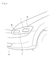
Fig. 1 is an illustration diagram schematically showing vehicle headlights to which the present invention is applied; -
Fig. 2 is a perspective view schematically showing a cooling device for the vehicle headlights according to the first embodiment of the present invention; -
Fig. 3 is a cross-sectional view schematically showing the cooling device for a first light shown inFig. 2 ; -
Fig. 4 is an illustration diagram showing the heat pipes used in the cooling device shown inFig. 2 ; -
Fig. 5 is an illustration diagram showing a heat sink used in the cooling device shown inFig. 2 ; -
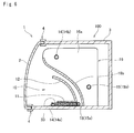
Fig. 6 is a cross-sectional view schematically showing the cooling device for the vehicle headlights according to the second embodiment of the present invention; -
Fig. 7 is a perspective view showing the cooling device for the vehicle headlights according to the third embodiment of the present invention; -
Fig. 8 is an illustration diagram showing the heat pipes used in the cooling device shown inFig. 7 ; -
Fig. 9 is a cross-sectional view schematically showing the cooling device for the first light shown inFig. 7 ; -
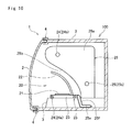
Fig. 10 is a cross-sectional view schematically showing the cooling device for the second light shown inFig. 7 ; -
Fig. 11 is a perspective view schematically showing the cooling device for the vehicle headlights according to the fourth embodiment of the present invention; -
Fig. 12 is a front view showing a motion and an arrangement of a piezo fan for the first light shown in theFig. 11 ; -
Fig. 13 is a perspective view schematically showing the cooling device for the vehicle headlights according to the fifth embodiment of the present invention; and -
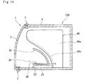
Fig. 14 is a cross-sectional view schematically showing the cooling device for a second light shown inFig. 2 . - Hereinafter, the present invention will be explained in more details with reference to the accompanying drawings. An example of the vehicle headlights to which the present invention is applied is shown in
Fig. 1 . Aheadlight 1 is comprised of alens 2 made of resin that is fitted into a front grille of a vehicle Ve, afirst light 10 and asecond light 20 whose brightness are different respectively. The lights emitted from thefirst light 10 and thesecond light 20 penetrate through thelens 2 as an outer lens to illuminate a road ahead. - In the
headlight 1 shown inFig. 1 , thefirst light 10 is situated outside of the second light 20 in the width direction of the vehicle Ve. In both of thefirst light 10 and thesecond light 20, a light emitting device (to be abbreviated as the "LED" hereinafter) is individually employed as a light source. According to the example, the light emitted from thefirst light 10 is brighter than that emitted from thesecond light 20. Those first andsecond lights - Here will be explained the first embodiment of the
headlight 1 with reference toFigs. 2 and3 .Fig. 2 is a perspective view showing an inner structure of theheadlight 1, andFig. 3 is a cross-sectional view of thefirst light 10 of theheadlight 1. As shown inFig. 3 thefirst light 10 and thesecond light 20 are arranged in ahousing 3, and a front opening of thehousing 3 is closed by thelens 2. A sealingmember 4 is arranged on an opening edge of thehousing 3, and an outer edge of thelens 2 is fitted into the sealingmember 4. Here, a configuration of the sealingmember 4 should not be limited to the configuration shown inFig. 3 , and material of which should also not be limited to the specific material. According to the preferable embodiments of the present invention,resin material 4 is used to form the sealing member. Thus, thehousing 3 serves as an outer casing of a unit of theheadlight 1 to be fitted into a frame (not shown) of the vehicle Ve. In addition, a ventilation (not shown), e.g., a slit or the like is formed on a wall of thehousing 3 so that a communication between an interior space of thehousing 3 and an exterior is provided. Here, inFig. 2 , a dotted-dashed line indicates thehousing 3, and a dashed line indicates the outer edge of thelens 2 or the sealingmember 4. - According to the embodiment shown in
Fig. 2 , thefirst light 10 is provided with a pair ofLEDs 11 juxtaposed in the width direction, and thesecond light 20 is provided with a pair ofLEDs 21 juxtaposed in the width direction. For instance, a packaged light source in which an LED chip placed on a square board is connected to a not shown electronic circuit can be used as thoseLEDs LEDs - In the
housing 3, theLEDs LED 11 ahead of the vehicle Ve, thefirst light 10 is provided with adomed reflector 12 covering thefirst light 10 from behind and above. Likewise, in order to reflect the light emitted by theLED 21 ahead of the vehicle Ve, thesecond light 20 is also provided with areflector 22 covering the second light 20 from behind and above. Here, configurations of thereflectors - Next, a
cooling device 100 arranged in thehousing 3 will be explained hereinafter. Thefirst light 10 and thesecond light 20 are individually provided with thecooling device 100 to cool theheat generating LEDs cooling device 100 for thefirst light 10 is adapted to collect the heat resulting from light emission of theLED 11 by aheat collector 13, and to radiate the heat from theheat sink 16 through a pair ofheat pipes cooling device 100 for thefirst light 20 is adapted to collect the heat resulting from light emission of theLED 21 by aheat collector 23, and to radiate the heat from theheat sink 26 through a pair ofheat pipes housing 3, the heats generated by theLEDs housing 3. - In the
cooling device 100 for thefirst light 10, theheat collector 13 is installed on the bottom of thehousing 3, and theLED 11 is mounted on theheat collector 13. That is, a lower face of the board of theLED 11 and the upper face of theheat collector 13 are contacted tightly to each other so that the heat of theLED 11 can be transferred to theheat collector 13. In other words, theheat collector 13 is a flat cuboid heat conductive block made of material having high heat conductivity. Therefore, the heat generated by theLED 11 is transferred to theheat collector 13 homogeneously and entirely. - According to the preferred embodiment, the
heat collector 13 is disposed longitudinally in a width direction of the vehicle Ve, and a pair ofLEDs heat collector 13. Accordingly, the heats of theLEDs 11 are drawn through the upper face of theheat collector 13 and spread radially downwardly in theheat collector 13. - The
heat collector 13 is connected with theheat sink 16 though a pair ofheat pipes heat collector 13 is transported to theheat sink 16 through theheat pipes heat pipes heat pipe Fig. 4 shows a structure of eachfirst heat pipe 14 andsecond heat pipe 15 of thecooling device 100 shown inFig. 2 . - As illustrated in
Fig 4 , eachfirst heat pipe 14 andsecond heat pipe 15 are shaped into U-shape. Specifically, thefirst heat pipe 14 is comprised of an evaporatingportion 14a, a condensingportion 14b extending parallel to the evaporatingportion 14a, and an insulatingportion 14c connecting the evaporatingportion 14a with the condensingportion 14b. Likewise, thesecond heat pipe 15 is comprised of an evaporatingportion 15a, a condensingportion 15b extending parallel to the evaporatingportion 15a, and an insulatingportion 15c connecting the evaporatingportion 15a with the condensingportion 15b. Here, the insulatingportion 14c of thefirst heat pipe 14 is formed to be longer than the insulatingportion 15c of thesecond heat pipe 15 thereby extending a heat transfer distance of thefirst heat pipe 14 to be longer than that of thesecond heat pipe 15. Optionally, thesecond heat pipe 15 may be formed to have a larger diameter than that of thefirst heat pipe 14. - In addition, the evaporating
portion 14a is partially flattened to form aflat contact surface 14d and the evaporatingportion 15a is partially flattened to form aflat surface 15d. Therefore, each contact area between theheat collector 13 and theflat contact surface 14d of thefirst heat pipe 14 and theflat contact surface 15d of thesecond heat pipe 15 are enlarged to enhance heat transfer efficiency therebetween. - Specifically, as shown in
Fig. 3 , theflat contact surface 14d of the evaporatingportion 14a is contacted with a front long side of theheat collector 13, and theflat contact surface 15d of the evaporatingportion 15a is contacted with a rear long side of theheat collector 13. Therefore, the heat is drawn from theLED 11 through theheat collector 13, and the working fluids in the evaporatingportions heat collector 13. On the other hand, the condensingportion 14b of thefirst heat pipe 14 and the condensingportion 15b of thesecond heat pipe 15 individually penetrate through an array offins 16. - As shown in
Fig. 2 , theheat sink 16 is disposed behind (i.e., in the back side) of thereflector 12. Theheat sink 16 is comprised of a base 16b covering thereflector 12 from behind and above, andfins 16a erected vertically while being juxtaposed in the width direction to extend from thebase 16b in the opposite side of thereflector 12. Accordingly, a plurality of flow passages for vertically letting through the air are formed between thefins 16a. An arrangement of the fin allay of theheat sink 16 is shown inFig. 5 . - As shown in
Fig. 5 , a first through-hole 16c to which thefirst heat pipe 14 is inserted is formed on an upper section of eachfin 16a of theheat sink 16, and a second through-hole 16d to which thesecond heat pipe 15 is inserted is formed on eachfin 16a at a lower level than the first through-hole 16c. A surface area of thefin 16a above the first through-hole 16c is larger than that below the second through-hole 16d. That is, a heat capacity of the upper section of thefin 16a is larger than that of the lower section. In addition, both of the first through-hole 16c and the second through-hole 16d are formed at levels higher than theheat collector 13. - The
first heat pipe 14 is inserted into each first through-hole 16c of the fin allay in a manner such that the condensingportion 14b is contacted with an inner circumference of the first through-hole 16c. Likewise, thesecond heat pipe 15 is inserted into each second through-hole 16d of the fin allay in a manner such that the condensingportion 15b is contacted with an inner circumference of the second through-hole 16d. Accordingly, the condensingportions portions fins 16a are contacted to the bottom of thehousing 3 inFig. 3 , thefins 16a may be isolated from the bottom of thehousing 3. - In the
first heat pipe 14, the working fluid is evaporated at the evaporatingportion 14a, and the heat is transported to the condensingportion 14b by the vapor of the working fluid to be radiated from thefins 16a. Consequently, the working fluid in the vapor phase is condensed into the liquid phase at the condensingportion 14b. The working fluid thus condensed is returned to the evaporatingportion 14a by a capillary force or gravity. Likewise, in thesecond heat pipe 15, the working fluid is evaporated at the evaporatingportion 15a, and condensed into the liquid phase at the condensingportion 15b as a result of radiating the heat from thefins 16a and returned to the evaporatingportion 15a by a capillary force or gravity. Thus, in thecooling device 100 for thefirst light 10, theLED 11 as a heat-generating member is connected to theheat sink 16 as a radiation device through theheat pipes LEDs 11 is radiated to the internal space of thehousing 3. - In the
cooling device 100 for thesecond light 20, theheat collector 23 is installed on the bottom of thehousing 3, and theLED 21 is mounted on theheat collector 23. That is, a lower face of the board of theLED 21 and the upper face of theheat collector 23 are contacted tightly to each other so that the heat generated by theLED 21 can be conducted to theheat collector 23. In other words, theheat collector 23 is a flat rectangular heat conductive structure made of material having high heat conductivity. Therefore, the heat generated by theLED 21 is conducted to theheat collector 23 homogeneously and entirely. - According to the preferred embodiment, the
heat collector 23 is disposed longitudinally in a width direction of the vehicle Ve, and a pair ofLEDs heat collector 23. Accordingly, the heats of theLEDs 21 are conducted to the width center of the upper face of theheat collector 23 and then the heat spread radially downwardly in theheat collector 23. - The
heat collector 23 is connected with theheat sink 26 though a pair ofheat pipes heat collector 23 is conducted to theheat pipes heat sink 26 through theheat pipes heat pipes heat pipe Fig. 4 shows a structure of eachfirst heat pipe 24 andsecond heat pipe 25 of thecooling device 100 shown inFig. 2 . - As illustrated in
Fig 4 , eachfirst heat pipe 24 andsecond heat pipe 25 are shaped into U-shape. Specifically, thefirst heat pipe 24 is comprised of an evaporatingportion 24a, a condensingportion 24b extending parallel to the evaporatingportion 24a, and an insulatingportion 24c connecting the evaporatingportion 24a with the condensingportion 24b. Likewise, thesecond heat pipe 25 is comprised of an evaporatingportion 25a, a condensingportion 25b extending parallel to the evaporatingportion 25a, and an insulatingportion 25c connecting the evaporatingportion 25a with the condensingportion 25b. Here, the insulatingportion 24c of thefirst heat pipe 24 is formed to be longer than the insulatingportion 25c of thesecond heat pipe 25 thereby extending a heat transfer distance of thefirst heat pipe 24 to be longer than that of thesecond heat pipe 25. Optionally, thesecond heat pipe 25 may be formed to have a larger diameter than that of thefirst heat pipe 24. - In addition, an outer surface of the evaporating
portion 24a is partially flattened to form aflat surface 24d contacted with a front long side of theheat collector 23. Likewise, an outer surface of the evaporatingportion 25a is partially flattened to form aflat surface 25d contacted with a rear long side of theheat collector 23. Therefore, each contact area between theheat collector 23 and eachheat pipe portion 24a of thefirst heat pipe 24 and the evaporatingportion 25a of thesecond heat pipe 25 extend parallel to each other in the width direction across theheat collector 23. - The heat generated by the
LED 21 is conducted individually to the evaporatingportions heat collector 23, and the working fluids held therein are evaporated by the heat from theLED 21. On the other hand, the condensingportion 24b of thefirst heat pipe 24 and the condensingportion 25b of thesecond heat pipe 25 individually penetrate through an array offins 26. - As shown in
Fig. 2 , theheat sink 26 is disposed behind (i.e., in the back side) of thereflector 22. Theheat sink 26 is comprised of a base 26b covering thereflector 22 from behind and above, andfins 26a erected vertically while being juxtaposed in the width direction to extend from thebase 26b in the opposite side of thereflector 22. Accordingly, a plurality of flow passages for vertically letting through the air are formed between thefins 26a. An arrangement of the fin allay of theheat sink 26 is shown inFig. 5 . - As shown in
Fig. 5 , a first through-hole 26c to which thefirst heat pipe 24 is inserted is formed on an upper section of eachfin 26a of theheat sink 26, and a second through-hole 26d to which thesecond heat pipe 25 is inserted is formed on eachfin 26a at a lower level than the first through-hole 26c. A surface area of thefin 26a above the first through-hole 26c is larger than that below the second through-hole 26d. That is, a heat capacity of the upper section of thefin 26a is larger than that of the lower section. In addition, both of the first through-hole 26c and the second through-hole 26d are formed at levels higher than theheat collector 23. Here, theheat sink 16 for thefirst light 10 may be formed in the shape of theheat sink 26 for thesecond light 20. Alternatively, theheat sink 16 may be either the same as or different size from theheat sink 26. For example, theheat sink 16 may be larger than theheat sink 26. - The
first heat pipe 24 is inserted into each first through-hole 26c of the fin allay in a manner such that the condensingportion 24b is contacted with an inner circumference of the first through-hole 26c. Likewise, thesecond heat pipe 15 is inserted into each second through-hole 26d of the fin allay in a manner such that the condensingportion 25b is contacted with an inner circumference of the second through-hole 26d. Accordingly, the condensingportions portions fins 26a are contacted to the bottom of thehousing 3, thefins 26a may be isolated from the bottom of thehousing 3. - In the
first heat pipe 24, the working fluid is evaporated at the evaporatingportion 24a, and the heat is transported to the condensingportion 24b by the vapor of the working fluid to be radiated from thefins 26a. Consequently, the working fluid in the vapor phase is condensed into the liquid phase at the condensingportion 24b. The working fluid thus condensed is returned to the evaporatingportion 24a by a capillary force or gravity. Likewise, in thesecond heat pipe 25, the working fluid is evaporated at the evaporatingportion 25a, and condensed into the liquid phase at the condensingportion 25b as a result of radiating the heat from thefins 26a and returned to the evaporatingportion 25a by a capillary force or gravity. Thus, in thecooling device 100 for thesecond light 20, theLED 21 as a heat-generating member is connected to theheat sink 26 as a radiation device through theheat pipes LEDs 21 is radiated to the internal space of thehousing 3. - As described, according to the first embodiment of the cooling device for the headlights, the heat sink serving as the heat radiating member is arranged in the housing of the headlights so that the LEDs can be cooled efficiently without blocking lights from the LEDs. In addition, a flexibility of design of the heat sink and the housing will not be restricted. As also described, the condensing portion of each heat pipe individually penetrate through the upper section and the lower section of the fins while being contacted therewith, and the area of the lower section of the fin is smaller than that of the upper section. Therefore, a chimney effect can be induced to allow the vapor phase working fluid to flow upwardly through the flow passages between the fins. Consequently, the heat of the LEDs can be efficiently radiated from the heat sink so that cooling capacity for LEDs can be enhanced. In addition, since the area of the lower section of the fin is thus smaller than that of the upper section, the heat capacity of the lower section of the fins is smaller than that of the upper section. That is, the temperature of the lower section of the fin is raised faster than that of the upper section. Therefore, the upward stream of the working fluid can be further expedited so that the heat of the LEDs can be radiated from the fins efficiently.
- The cooling device for vehicle headlights should not be limited to the first embodiment, and may be modified within the spirit of the present invention.
- For example, according to the second embodiment of the present invention, a vapor chamber (i.e., a flat heat pipe) is employed as at least any one of the
heat collector 13 of thefirst light 10 and theheat collector 23 of thesecond light 20 instead of the heat conductive block. Referring now toFig. 6 , there is shown an example in which the vapor chamber is used as the heat collector in thefirst light 10. Here, in the following explanation of the second embodiment, common reference numerals are allotted to the elements identical to those in the first embodiment, and detailed explanation for those elements will be omitted. - As shown in
Fig. 6 , according to the second embodiment, avapor chamber 33 is laid on the bottom of thehousing 3, and theLED 11 is disposed on the upper face of thevapor chamber 33. The front face of thevapor chamber 33 is contacted with the evaporatingportion 14a of theheat pipe 14, and the rear face of thevapor chamber 33 is contacted with the evaporatingportion 15a of theheat pipe 15. As the conventional vapor chamber, a small amount of the working fluid is encapsulated in a sealed internal space of thevapor chamber 33, and a wick is disposed therein. According to the second embodiment, therefore, the heat of theLED 11 can be transported efficiently to theheat sink 16 utilizing the heat transportation property of thevapor chamber 33 so that the cooling performance of thecooling device 100 can be enhanced. - According to the third embodiment of the cooling device, as shown in
Fig. 7 , thefirst heat pipe 14 is modified to contact the condensing portion thereof with thehousing 3. In the following explanation of the third embodiment, common reference numerals are also allotted to the elements identical to those in the foregoing embodiments, and detailed explanation for those elements will also be omitted. - As illustrated in
Fig. 7 , in thefirst light 10, asecond condensing portion 14e is extended from thefirst heat pipe 14 to be contacted with the bottom of thehousing 3. Also, in thesecond light 20, asecond condensing portion 25e is extended from thesecond heat pipe 25 to be contacted with the bottom of thehousing 3. Details of structures ofheat pipes Fig. 8 . - As shown in
Fig. 8 , in thefirst heat pipe 14 of thefirst light 10, a branch is extended from an intermediate portion of the evaporatingportion 14a contacted with theheat collector 13 to protrude in the forward direction, and bent downwardly backwardly at a predetermined portion to form a U-shaped branch. In the U-shaped branch, specifically, a portion between the evaporatingportion 14a and the bent portion serves as a secondinsulting portion 14f, and a portion extending further than the bent portion is contacted with thehousing 3 to serve as thesecond condensing portion 14e. Thus, the evaporatingportion 14a is connected to thefirst condensing portion 14b via the first insulatingportion 14c, and also connected to thesecond condensing portion 14e via the second insulatingportion 14f. - In turn, in the
second heat pipe 25 of thesecond light 20, a branch is extended in parallel with theevaporation portion 25a contacted with theheat collector 23 from an intermediate portion, and a leading end of the branch is bent downwardly and further bent backwardly to form an L-shaped leading end. In the branch, specifically, a portion extending along the evaporatingportion 25a serves as a secondinsulting portion 25f, and a portion of the L-shaped leading end extending backwardly along the bottom of thehousing 3 serve as thesecond condensing portion 25e. Thus, the evaporatingportion 25a is connected to thefirst condensing portion 25b via the first insulatingportion 25c, and also connected to thesecond condensing portion 25e via the second insulatingportion 25f. - As shown in
Fig. 9 , in thefirst heat pipe 14, thefirst condensing portion 14b penetrates through an array offins 16a while being contacted thereto, and thesecond condensing portion 14e is contacted with the bottom of thehousing 3. As also shown inFig. 10 , in thesecond heat pipe 25, thefirst condensing portion 25b penetrates through an array offins 26a while being contacted thereto, and thesecond condensing portion 25e is contacted with the bottom of thehousing 3. Thus, both of thefirst heat pipe 14 and thesecond heat pipe 15 conduct the heats to different objects. - Thus, according to the third embodiment of the cooling device for the headlights, each heat pipe is individually provided with the branch functioning as the second condensing portion contacted with the housing. Accordingly, the heat radiating capacity of each condensing portion can be increased so that the heat transporting capacity of each first and second heat pipe can be enhanced to cool the LEDs effectively.
- The structure of each branch may be modified arbitrarily in a manner such that the second condensing portion of the first heat pipe is contacted with the housing, and that the second condensing portion of the second heat pipe is contacted with the housing.
- According to the fourth embodiment, as shown in
Fig. 11 , the cooling device is provided with a fan for cooling the LEDs by blowing air. In the following explanation of the fourth embodiment, common reference numerals are also allotted to the elements identical to those in the foregoing embodiments, and detailed explanation for those elements will also be omitted. - As illustrated in
Fig. 11 , thefirst light 10 is provided with apiezo fan 18 for sending air to theLED 11, and thesecond light 20 is provided with apiezo fan 28 for sending air to theLED 21. Eachpiezo fan pivotal fan piezoelectric element pivotal fan piezoelectric element LED piezo fan - The
piezo fan 18 is arranged in a manner not to block the incident light to thereflector 12 emitted from theLED 11 As shown inFig. 12 , thepiezo fan 18 is disposed inside of thecollector 13 in the width direction at a vertically higher level than theLED 11. As described, the vertical pivotal movement of thepivotal fan 18b is achieved by energizing thepiezoelectric element 18a to cause an inverse piezoelectric effect. That is, thepiezo fan 18 is disposed on the opposite side of the insulatingportions heat pipes - Specifically, the
piezo fan 18 is disposed at a site not to intervene in the reflection of the light of theLED 11 by thereflector 12. In other words, thepiezo fan 18 is arranged out of a reflection range of thereflector 12 in order not to block the light illuminating the road ahead of the vehicle. - Likewise, the
piezo fan 28 is arranged in a manner not to block the incident light of the second light 20 illuminating road ahead. Thepiezo fan 28 is disposed outside of thecollector 23 in the width direction at a vertically higher level than theLED 21. The vertical pivotal movement of thepivotal fan 28b is also achieved by energizing thepiezoelectric element 28a to cause an inverse piezoelectric effect. That is, thepiezo fan 28 is disposed on the opposite side of the insulatingportions heat pipes - Thus, according to the fourth embodiment of the cooling device for the headlights, the LED can be cooled by sending the air from the piezo fans over the surface of the LED. In addition, a flow rate of the airflow created by the piezo fan is faster than that created by an axial fan so that the LED can be cooled more efficiently.
- The location of each piezo fan should not be limited to the above-explained site. For example, the piezo fan may also be disposed on the opposite side of the heat collector where the insulating portion of the heat pipe extends. Alternatively, the piezo fan may also be situated above the reflector to send air vertically to the LEDs.
- According to the fifth embodiment of the present invention, as shown in
Fig. 13 , the cooling device is adapted to transport the heat of the LED to the heat sink without using the heat pipe. In the following explanation of the fifth embodiment, common reference numerals are also allotted to the elements identical to those in the foregoing embodiments, and detailed explanation for those elements will also be omitted. - According to the fifth embodiment,
heat sinks heat sinks heat sink 36 of thefirst light 10 is comprised of a plurality offins 36a, and theheat sink 46 of thesecond light 20 is comprised of a plurality offins 46a. - As shown in
Fig. 13 , theheat sink 36 is disposed behind thereflector 12. Theheat sink 36 is comprised of a base 36b covering thereflector 12 from behind, andfins 36a erected vertically while being juxtaposed in the width direction to extend from thebase 36b in the opposite side of thereflector 12. Accordingly, a plurality of flow passages for vertically letting through the air are formed between thefins 36a. According to the fifth embodiment, theheat collector 13 is attached to the lower portion of the base 36b to protrude horizontally ahead of thebase 36b. Optionally, theheat collector 13 may also be formed of DMS-1. TheLEDs 11 are disposed on theheat collector 13 so that the heats of theLEDs 11 are transported to thefin 36a through thebase 36b. - In turn, the
heat sink 46 is disposed behind thereflector 12. Theheat sink 46 is comprised of a base 46b covering thereflector 12 from behind, andfins 46a erected vertically while being juxtaposed in the width direction to extend from thebase 46b in the opposite side of thereflector 12. Accordingly, a plurality of flow passages for vertically letting through the air are formed between thefins 46a. According to the fifth embodiment, theheat collector 23 is attached to the lower portion of the base 46b to protrude horizontally ahead of thebase 46b. As described, theheat collector 23 may also be formed of DMS-1. TheLEDs 21 are also disposed on theheat collector 23 so that the heats of theLEDs 21 are transported to thefin 46a through thebase 46b. - The
piezo fan 18 of thefirst light 10 may be disposed on any of lateral sides of theheat collector 13. Likewise, thepiezo fan 28 of thesecond light 20 may also be disposed on any of lateral sides of theheat collector 23. Specifically, as shown inFig. 13 , thepiezo fan 18 is arranged on the inner side of theheat collector 13 in the width direction, and thepiezo fan 28 is arranged on the outer side of theheat collector 23 in the width direction. - According to the fifth embodiment, since the heat sinks 36 and 46 are made of DMS-1, the heat conductivity of the heat sinks can be enhanced so that the LEDs can be cooled more effectively. In addition, since the heat pipes are not used in this embodiment, a required space of the housing to hold the heat sink can be reduced so that the headlight can be downsized.
- The cooling device of the present invention may also be applied to headlights of any of transportation carriers, e.g., automobiles, railway vehicle, ocean ships and vessels, aircraft and so on.
- A cooling device for cooling an LED of vehicle headlight without restricting a design of a housing is provided. The cooling device is comprised of an LED held in a housing sealed with a lens, a reflector that reflects a light emitted from the light source, a heat collector on which the LED is mounted, a heat sink disposed behind the reflector, and a pair of heat pipes thermally connecting the heat collector and the heat sink. The heat sink is arranged inside of the housing.
Claims (8)
- A cooling device for vehicle headlights, comprising:an LED light source held in a housing sealed with a lens;a reflector that reflects a light emitted from the LED light source;a heat sink that is disposed behind the reflector;a heat pipe that transports heat generated by the LED light source to the heat sink by a working fluid encapsulated therein;a flat cuboid vapor chamber that serves as a heat collector on which the LED light source is mounted;wherein the heat sink is comprised of a base covering the reflector from behind and above while keeping a distance therebetween, and a plurality of fins erected vertically to extend from the base in the opposite side of the reflector;wherein a surface area of lower section of the fin is smaller than that of an upper section;wherein the heat pipe includesa first heat pipe in which one of end portions is flattened to be contacted with a front long side of the vapor chamber, and the other end portion penetrates through the upper section of the fin while being contacted therewith, anda second heat pipe in which one of end portions is flattened to be contacted with a rear long side of the vapor chamber, and the other end portion penetrates through the upper section of the fin while being contacted therewith; andwherein the reflector is isolated from the vapor chamber and the heat pipes.
- The cooling device for vehicle headlights as claimed in claim 1, wherein the vapor chamber is comprised of:a sealed container;a working fluid held in the container; anda wick that performs a capillary action.
- The cooling device for vehicle headlights as claimed in claim 1, further comprising:a piezo fan that cools the LED light source by sending air over the LED light source;wherein the piezo fan is disposed at a site not to block an incident light to the reflector emitted from the LED light source.
- The cooling device for vehicle headlights as claimed in claim 1,
wherein each of the first and the second heat pipe is further comprised of a branch contacted with an inner face of the housing; and
wherein said one of the end portion serves as an evaporating portion, said other end portion serves as a condensing portion, and the branch serves as another condensing portion. - The cooling device for vehicle headlights as claimed in claim 2, further comprising:a piezo fan that cools the LED light source by sending air over the LED light source;wherein the piezo fan is disposed at a site not to block an incident light to the reflector emitted from the LED light source.
- The cooling device for vehicle headlights as claimed in claim 2,
wherein each of the first and the second heat pipe is further comprised of a branch contacted with an inner face of the housing; and
wherein said one of the end portion serves as an evaporating portion, said other end portion serves as a condensing portion, and the branch serves as another condensing portion. - The cooling device for vehicle headlights as claimed in claim 3,
wherein each of the first and the second heat pipe is further comprised of a branch contacted with an inner face of the housing; and
wherein said one of the end portion serves as an evaporating portion, said other end portion serves as a condensing portion, and the branch serves as another condensing portion. - The cooling device for vehicle headlights as claimed in claim 5,
wherein each of the first and the second heat pipe is further comprised of a branch contacted with an inner face of the housing; and
wherein said one of the end portion serves as an evaporating portion, said other end portion serves as a condensing portion, and the branch serves as another condensing portion.
Applications Claiming Priority (1)
| Application Number | Priority Date | Filing Date | Title |
|---|---|---|---|
| JP2013211852A JP5481596B1 (en) | 2013-10-09 | 2013-10-09 | Cooling device for vehicle headlight |
Publications (2)
| Publication Number | Publication Date |
|---|---|
| EP2860440A1 true EP2860440A1 (en) | 2015-04-15 |
| EP2860440B1 EP2860440B1 (en) | 2016-12-07 |
Family
ID=50749990
Family Applications (1)
| Application Number | Title | Priority Date | Filing Date |
|---|---|---|---|
| EP14187705.0A Active EP2860440B1 (en) | 2013-10-09 | 2014-10-06 | Cooling device for vehicle headlights |
Country Status (3)
| Country | Link |
|---|---|
| US (1) | US9188305B2 (en) |
| EP (1) | EP2860440B1 (en) |
| JP (1) | JP5481596B1 (en) |
Cited By (2)
| Publication number | Priority date | Publication date | Assignee | Title |
|---|---|---|---|---|
| DE102016000812A1 (en) * | 2016-01-26 | 2017-07-27 | Audi Ag | Electrical arrangement for a motor vehicle, motor vehicle and method for operating a synthetic jet |
| WO2021198851A1 (en) * | 2020-03-31 | 2021-10-07 | Tvs Motor Company Limited | Headlamp assembly |
Families Citing this family (12)
| Publication number | Priority date | Publication date | Assignee | Title |
|---|---|---|---|---|
| US10168018B2 (en) | 2014-02-25 | 2019-01-01 | Ford Global Technologies, Llc | Vehicle light fixture having internal heatsink for LED lamp |
| US9429293B2 (en) * | 2014-02-25 | 2016-08-30 | Ford Global Technologies, Llc | Vehicle light fixture having internal heatsink for LED lamp |
| KR101774806B1 (en) | 2015-12-01 | 2017-09-05 | 엘지전자 주식회사 | Lighting device module |
| CN105351856A (en) * | 2015-12-08 | 2016-02-24 | 丹阳俊龙车业有限公司 | LED (light-emitting diode) locomotive headlamp |
| AT518220B1 (en) * | 2016-02-02 | 2017-11-15 | Zkw Group Gmbh | Lighting unit for a motor vehicle |
| CN105674184A (en) * | 2016-02-02 | 2016-06-15 | 陕西科技大学 | Environment-friendly type laser automobile head lamp and manufacturing method thereof |
| JP6655824B2 (en) * | 2017-01-20 | 2020-02-26 | パナソニックIpマネジメント株式会社 | Imaging device |
| DE102018114765A1 (en) * | 2018-06-20 | 2019-12-24 | Zkw Group Gmbh | Motor vehicle headlamps |
| CN112524567B (en) * | 2020-12-10 | 2022-09-09 | 西安电子科技大学芜湖研究院 | A new type of high-power light source for automobiles |
| CN112923325A (en) * | 2021-04-12 | 2021-06-08 | 南通中科热控技术有限公司 | Locomotive headlamp with loop heat pipe heat radiation structure |
| KR102580444B1 (en) * | 2022-02-03 | 2023-09-20 | 에이치앤씨모빌리티 주식회사 | Head lamp cooling system |
| JP7795096B2 (en) | 2022-03-31 | 2026-01-07 | 日亜化学工業株式会社 | air purifier |
Citations (10)
| Publication number | Priority date | Publication date | Assignee | Title |
|---|---|---|---|---|
| WO2006052022A1 (en) * | 2004-11-12 | 2006-05-18 | Showa Denko K.K. | Automotive lighting fixture and lighting device |
| JP2006164967A (en) | 2004-11-12 | 2006-06-22 | Showa Denko Kk | Vehicle lamp and lighting device |
| JP2009087620A (en) | 2007-09-28 | 2009-04-23 | Toyoda Gosei Co Ltd | Vehicle headlight |
| EP2077420A1 (en) * | 2006-10-10 | 2009-07-08 | NeoBulb Technologies, Inc. | A semiconductor light-emitting module |
| WO2010002159A2 (en) * | 2008-07-04 | 2010-01-07 | 주식회사 미광엔비텍 | Heat-dissipating device using led for a lamp |
| JP2010129543A (en) | 2008-11-27 | 2010-06-10 | Samsung Led Co Ltd | Headlight for vehicle |
| JP2011081937A (en) * | 2009-10-05 | 2011-04-21 | Stanley Electric Co Ltd | Lighting tool for vehicle |
| EP2413030A2 (en) * | 2010-07-30 | 2012-02-01 | MicroBase Technology Corp. | Lamp Device, Cooling System and Cooling Module |
| US20120294002A1 (en) * | 2011-05-18 | 2012-11-22 | Phoseon Technology, Inc. | Vapor chamber cooling of solid-state light fixtures |
| WO2013001560A1 (en) * | 2011-06-27 | 2013-01-03 | 三菱電機株式会社 | Vehicle headlamp |
Family Cites Families (20)
| Publication number | Priority date | Publication date | Assignee | Title |
|---|---|---|---|---|
| JP2000322908A (en) * | 1999-05-10 | 2000-11-24 | Sakae Riken Kogyo Kk | Vehicle lamp and its cooling device |
| JP2003163479A (en) * | 2001-11-28 | 2003-06-06 | Hitachi Ltd | Electronic equipment cooling device |
| JP4102240B2 (en) * | 2003-04-08 | 2008-06-18 | 株式会社小糸製作所 | Vehicle headlamp |
| US6910794B2 (en) * | 2003-04-25 | 2005-06-28 | Guide Corporation | Automotive lighting assembly cooling system |
| TWI225713B (en) * | 2003-09-26 | 2004-12-21 | Bin-Juine Huang | Illumination apparatus of light emitting diodes and method of heat dissipation thereof |
| JP4053489B2 (en) * | 2003-11-04 | 2008-02-27 | 株式会社小糸製作所 | Vehicle headlamp |
| US7300187B2 (en) * | 2005-10-24 | 2007-11-27 | L&C Lighting Technology Corp. | LED device with an active heat-dissipation device |
| US7344289B2 (en) * | 2005-12-07 | 2008-03-18 | Visteon Global Technologies, Inc. | Headlamp assembly with integrated reflector and heat sink |
| CN100583470C (en) * | 2006-12-15 | 2010-01-20 | 富准精密工业(深圳)有限公司 | LED heat sink combination |
| TWI326498B (en) * | 2006-12-29 | 2010-06-21 | Neobulb Technologies Inc | Light-emitting diode illuminating equipment |
| JP2008309453A (en) * | 2007-06-18 | 2008-12-25 | Fujikura Ltd | Cooling module and LED lamp |
| US20100067224A1 (en) * | 2007-08-24 | 2010-03-18 | Yu-Chao Wu | Light emitting system |
| TWM334060U (en) * | 2007-11-28 | 2008-06-11 | Man Zai Ind Co Ltd | Car lamp head having heat-dissipation device |
| FR2940407B1 (en) * | 2008-12-18 | 2013-11-22 | Valeo Vision Sas | COOLING DEVICE OF AN OPTICAL MODULE FOR AUTOMOTIVE PROJECTOR |
| JP2010262903A (en) * | 2009-05-11 | 2010-11-18 | Koito Mfg Co Ltd | Vehicle lighting |
| JP2011249057A (en) * | 2010-05-25 | 2011-12-08 | Stanley Electric Co Ltd | Vehicular headlight |
| US8710526B2 (en) * | 2011-08-30 | 2014-04-29 | Abl Ip Holding Llc | Thermal conductivity and phase transition heat transfer mechanism including optical element to be cooled by heat transfer of the mechanism |
| JP3174401U (en) * | 2011-10-31 | 2012-03-22 | 恵安株式会社 | lighting equipment |
| JP2013131316A (en) * | 2011-12-20 | 2013-07-04 | Yamaha Motor Co Ltd | Led headlamp for vehicle |
| JP2013134855A (en) * | 2011-12-26 | 2013-07-08 | Mitsubishi Electric Corp | Lighting fixture |
-
2013
- 2013-10-09 JP JP2013211852A patent/JP5481596B1/en active Active
-
2014
- 2014-10-06 US US14/506,787 patent/US9188305B2/en active Active
- 2014-10-06 EP EP14187705.0A patent/EP2860440B1/en active Active
Patent Citations (10)
| Publication number | Priority date | Publication date | Assignee | Title |
|---|---|---|---|---|
| WO2006052022A1 (en) * | 2004-11-12 | 2006-05-18 | Showa Denko K.K. | Automotive lighting fixture and lighting device |
| JP2006164967A (en) | 2004-11-12 | 2006-06-22 | Showa Denko Kk | Vehicle lamp and lighting device |
| EP2077420A1 (en) * | 2006-10-10 | 2009-07-08 | NeoBulb Technologies, Inc. | A semiconductor light-emitting module |
| JP2009087620A (en) | 2007-09-28 | 2009-04-23 | Toyoda Gosei Co Ltd | Vehicle headlight |
| WO2010002159A2 (en) * | 2008-07-04 | 2010-01-07 | 주식회사 미광엔비텍 | Heat-dissipating device using led for a lamp |
| JP2010129543A (en) | 2008-11-27 | 2010-06-10 | Samsung Led Co Ltd | Headlight for vehicle |
| JP2011081937A (en) * | 2009-10-05 | 2011-04-21 | Stanley Electric Co Ltd | Lighting tool for vehicle |
| EP2413030A2 (en) * | 2010-07-30 | 2012-02-01 | MicroBase Technology Corp. | Lamp Device, Cooling System and Cooling Module |
| US20120294002A1 (en) * | 2011-05-18 | 2012-11-22 | Phoseon Technology, Inc. | Vapor chamber cooling of solid-state light fixtures |
| WO2013001560A1 (en) * | 2011-06-27 | 2013-01-03 | 三菱電機株式会社 | Vehicle headlamp |
Cited By (3)
| Publication number | Priority date | Publication date | Assignee | Title |
|---|---|---|---|---|
| DE102016000812A1 (en) * | 2016-01-26 | 2017-07-27 | Audi Ag | Electrical arrangement for a motor vehicle, motor vehicle and method for operating a synthetic jet |
| WO2021198851A1 (en) * | 2020-03-31 | 2021-10-07 | Tvs Motor Company Limited | Headlamp assembly |
| CN115398143A (en) * | 2020-03-31 | 2022-11-25 | Tvs电机股份有限公司 | Headlamp assembly |
Also Published As
| Publication number | Publication date |
|---|---|
| US9188305B2 (en) | 2015-11-17 |
| EP2860440B1 (en) | 2016-12-07 |
| US20150098235A1 (en) | 2015-04-09 |
| JP5481596B1 (en) | 2014-04-23 |
| JP2015076275A (en) | 2015-04-20 |
Similar Documents
| Publication | Publication Date | Title |
|---|---|---|
| EP2860440B1 (en) | Cooling device for vehicle headlights | |
| CN101389901B (en) | car headlights | |
| EP2442023B1 (en) | Head lamp assembly and vehicle including the same | |
| JP5405043B2 (en) | Vehicle lighting | |
| JP5031044B2 (en) | Automotive headlamp | |
| US7249868B2 (en) | Lamp housing with interior cooling by a thermoelectric device | |
| CN102003668A (en) | Headlamp for vehicle | |
| JP2008226843A (en) | Automotive lighting or signaling device having an outer wall with a heat exchanger | |
| JP5243505B2 (en) | Vehicle headlamp | |
| CN209909794U (en) | Cooling unit and vehicle lamp | |
| KR20150015901A (en) | Automobile led head lamp module using flexible substrate and heat sink structure thereof | |
| JP2010102997A (en) | Led lighting fixture for vehicle | |
| JP5602970B1 (en) | Defrost structure for vehicle headlights | |
| JP2014135350A (en) | Heat sink | |
| JP2008047383A (en) | Vehicle lighting | |
| JP2008047385A (en) | Vehicle lighting | |
| US10851964B2 (en) | Lighting fixture for vehicle | |
| JPWO2013001560A1 (en) | Automotive headlamp | |
| JP2013016681A (en) | Heat radiation member and heat radiation mechanism | |
| JP4661740B2 (en) | LED lights for vehicles | |
| JP5390781B2 (en) | Light source cooling device | |
| JP2009283406A (en) | Vehicular headlamp device | |
| JP2014207211A (en) | Lighting device | |
| KR20150019787A (en) | Heatsink increasing heat emitting performance and Head lamp having it for vehicle | |
| JP2014103058A (en) | LED lamp |
Legal Events
| Date | Code | Title | Description |
|---|---|---|---|
| PUAI | Public reference made under article 153(3) epc to a published international application that has entered the european phase |
Free format text: ORIGINAL CODE: 0009012 |
|
| 17P | Request for examination filed |
Effective date: 20141006 |
|
| AK | Designated contracting states |
Kind code of ref document: A1 Designated state(s): AL AT BE BG CH CY CZ DE DK EE ES FI FR GB GR HR HU IE IS IT LI LT LU LV MC MK MT NL NO PL PT RO RS SE SI SK SM TR |
|
| AX | Request for extension of the european patent |
Extension state: BA ME |
|
| 17Q | First examination report despatched |
Effective date: 20160115 |
|
| RIC1 | Information provided on ipc code assigned before grant |
Ipc: F21V 29/51 20150101ALI20160429BHEP Ipc: F21V 29/63 20150101ALN20160429BHEP Ipc: F21S 8/10 20060101AFI20160429BHEP Ipc: F21Y 115/10 20160101ALI20160429BHEP |
|
| GRAP | Despatch of communication of intention to grant a patent |
Free format text: ORIGINAL CODE: EPIDOSNIGR1 |
|
| INTG | Intention to grant announced |
Effective date: 20160615 |
|
| GRAS | Grant fee paid |
Free format text: ORIGINAL CODE: EPIDOSNIGR3 |
|
| GRAA | (expected) grant |
Free format text: ORIGINAL CODE: 0009210 |
|
| AK | Designated contracting states |
Kind code of ref document: B1 Designated state(s): AL AT BE BG CH CY CZ DE DK EE ES FI FR GB GR HR HU IE IS IT LI LT LU LV MC MK MT NL NO PL PT RO RS SE SI SK SM TR |
|
| REG | Reference to a national code |
Ref country code: GB Ref legal event code: FG4D |
|
| REG | Reference to a national code |
Ref country code: CH Ref legal event code: EP Ref country code: AT Ref legal event code: REF Ref document number: 852067 Country of ref document: AT Kind code of ref document: T Effective date: 20161215 |
|
| REG | Reference to a national code |
Ref country code: IE Ref legal event code: FG4D |
|
| REG | Reference to a national code |
Ref country code: DE Ref legal event code: R096 Ref document number: 602014005307 Country of ref document: DE |
|
| PG25 | Lapsed in a contracting state [announced via postgrant information from national office to epo] |
Ref country code: LV Free format text: LAPSE BECAUSE OF FAILURE TO SUBMIT A TRANSLATION OF THE DESCRIPTION OR TO PAY THE FEE WITHIN THE PRESCRIBED TIME-LIMIT Effective date: 20161207 |
|
| REG | Reference to a national code |
Ref country code: LT Ref legal event code: MG4D |
|
| REG | Reference to a national code |
Ref country code: NL Ref legal event code: MP Effective date: 20161207 |
|
| PG25 | Lapsed in a contracting state [announced via postgrant information from national office to epo] |
Ref country code: LT Free format text: LAPSE BECAUSE OF FAILURE TO SUBMIT A TRANSLATION OF THE DESCRIPTION OR TO PAY THE FEE WITHIN THE PRESCRIBED TIME-LIMIT Effective date: 20161207 Ref country code: GR Free format text: LAPSE BECAUSE OF FAILURE TO SUBMIT A TRANSLATION OF THE DESCRIPTION OR TO PAY THE FEE WITHIN THE PRESCRIBED TIME-LIMIT Effective date: 20170308 Ref country code: SE Free format text: LAPSE BECAUSE OF FAILURE TO SUBMIT A TRANSLATION OF THE DESCRIPTION OR TO PAY THE FEE WITHIN THE PRESCRIBED TIME-LIMIT Effective date: 20161207 Ref country code: NO Free format text: LAPSE BECAUSE OF FAILURE TO SUBMIT A TRANSLATION OF THE DESCRIPTION OR TO PAY THE FEE WITHIN THE PRESCRIBED TIME-LIMIT Effective date: 20170307 |
|
| REG | Reference to a national code |
Ref country code: AT Ref legal event code: MK05 Ref document number: 852067 Country of ref document: AT Kind code of ref document: T Effective date: 20161207 |
|
| PG25 | Lapsed in a contracting state [announced via postgrant information from national office to epo] |
Ref country code: FI Free format text: LAPSE BECAUSE OF FAILURE TO SUBMIT A TRANSLATION OF THE DESCRIPTION OR TO PAY THE FEE WITHIN THE PRESCRIBED TIME-LIMIT Effective date: 20161207 Ref country code: ES Free format text: LAPSE BECAUSE OF FAILURE TO SUBMIT A TRANSLATION OF THE DESCRIPTION OR TO PAY THE FEE WITHIN THE PRESCRIBED TIME-LIMIT Effective date: 20161207 Ref country code: RS Free format text: LAPSE BECAUSE OF FAILURE TO SUBMIT A TRANSLATION OF THE DESCRIPTION OR TO PAY THE FEE WITHIN THE PRESCRIBED TIME-LIMIT Effective date: 20161207 Ref country code: HR Free format text: LAPSE BECAUSE OF FAILURE TO SUBMIT A TRANSLATION OF THE DESCRIPTION OR TO PAY THE FEE WITHIN THE PRESCRIBED TIME-LIMIT Effective date: 20161207 |
|
| PG25 | Lapsed in a contracting state [announced via postgrant information from national office to epo] |
Ref country code: NL Free format text: LAPSE BECAUSE OF FAILURE TO SUBMIT A TRANSLATION OF THE DESCRIPTION OR TO PAY THE FEE WITHIN THE PRESCRIBED TIME-LIMIT Effective date: 20161207 |
|
| PG25 | Lapsed in a contracting state [announced via postgrant information from national office to epo] |
Ref country code: CZ Free format text: LAPSE BECAUSE OF FAILURE TO SUBMIT A TRANSLATION OF THE DESCRIPTION OR TO PAY THE FEE WITHIN THE PRESCRIBED TIME-LIMIT Effective date: 20161207 Ref country code: IS Free format text: LAPSE BECAUSE OF FAILURE TO SUBMIT A TRANSLATION OF THE DESCRIPTION OR TO PAY THE FEE WITHIN THE PRESCRIBED TIME-LIMIT Effective date: 20170407 Ref country code: SK Free format text: LAPSE BECAUSE OF FAILURE TO SUBMIT A TRANSLATION OF THE DESCRIPTION OR TO PAY THE FEE WITHIN THE PRESCRIBED TIME-LIMIT Effective date: 20161207 Ref country code: EE Free format text: LAPSE BECAUSE OF FAILURE TO SUBMIT A TRANSLATION OF THE DESCRIPTION OR TO PAY THE FEE WITHIN THE PRESCRIBED TIME-LIMIT Effective date: 20161207 Ref country code: RO Free format text: LAPSE BECAUSE OF FAILURE TO SUBMIT A TRANSLATION OF THE DESCRIPTION OR TO PAY THE FEE WITHIN THE PRESCRIBED TIME-LIMIT Effective date: 20161207 |
|
| PG25 | Lapsed in a contracting state [announced via postgrant information from national office to epo] |
Ref country code: PT Free format text: LAPSE BECAUSE OF FAILURE TO SUBMIT A TRANSLATION OF THE DESCRIPTION OR TO PAY THE FEE WITHIN THE PRESCRIBED TIME-LIMIT Effective date: 20170407 Ref country code: PL Free format text: LAPSE BECAUSE OF FAILURE TO SUBMIT A TRANSLATION OF THE DESCRIPTION OR TO PAY THE FEE WITHIN THE PRESCRIBED TIME-LIMIT Effective date: 20161207 Ref country code: IT Free format text: LAPSE BECAUSE OF FAILURE TO SUBMIT A TRANSLATION OF THE DESCRIPTION OR TO PAY THE FEE WITHIN THE PRESCRIBED TIME-LIMIT Effective date: 20161207 Ref country code: SM Free format text: LAPSE BECAUSE OF FAILURE TO SUBMIT A TRANSLATION OF THE DESCRIPTION OR TO PAY THE FEE WITHIN THE PRESCRIBED TIME-LIMIT Effective date: 20161207 Ref country code: BG Free format text: LAPSE BECAUSE OF FAILURE TO SUBMIT A TRANSLATION OF THE DESCRIPTION OR TO PAY THE FEE WITHIN THE PRESCRIBED TIME-LIMIT Effective date: 20170307 Ref country code: BE Free format text: LAPSE BECAUSE OF FAILURE TO SUBMIT A TRANSLATION OF THE DESCRIPTION OR TO PAY THE FEE WITHIN THE PRESCRIBED TIME-LIMIT Effective date: 20161207 Ref country code: AT Free format text: LAPSE BECAUSE OF FAILURE TO SUBMIT A TRANSLATION OF THE DESCRIPTION OR TO PAY THE FEE WITHIN THE PRESCRIBED TIME-LIMIT Effective date: 20161207 |
|
| REG | Reference to a national code |
Ref country code: DE Ref legal event code: R097 Ref document number: 602014005307 Country of ref document: DE |
|
| PLBE | No opposition filed within time limit |
Free format text: ORIGINAL CODE: 0009261 |
|
| STAA | Information on the status of an ep patent application or granted ep patent |
Free format text: STATUS: NO OPPOSITION FILED WITHIN TIME LIMIT |
|
| 26N | No opposition filed |
Effective date: 20170908 |
|
| REG | Reference to a national code |
Ref country code: DE Ref legal event code: R079 Ref document number: 602014005307 Country of ref document: DE Free format text: PREVIOUS MAIN CLASS: F21S0008100000 Ipc: F21S0043000000 |
|
| PG25 | Lapsed in a contracting state [announced via postgrant information from national office to epo] |
Ref country code: SI Free format text: LAPSE BECAUSE OF FAILURE TO SUBMIT A TRANSLATION OF THE DESCRIPTION OR TO PAY THE FEE WITHIN THE PRESCRIBED TIME-LIMIT Effective date: 20161207 Ref country code: DK Free format text: LAPSE BECAUSE OF FAILURE TO SUBMIT A TRANSLATION OF THE DESCRIPTION OR TO PAY THE FEE WITHIN THE PRESCRIBED TIME-LIMIT Effective date: 20161207 |
|
| PG25 | Lapsed in a contracting state [announced via postgrant information from national office to epo] |
Ref country code: MC Free format text: LAPSE BECAUSE OF FAILURE TO SUBMIT A TRANSLATION OF THE DESCRIPTION OR TO PAY THE FEE WITHIN THE PRESCRIBED TIME-LIMIT Effective date: 20161207 |
|
| REG | Reference to a national code |
Ref country code: CH Ref legal event code: PL |
|
| REG | Reference to a national code |
Ref country code: IE Ref legal event code: MM4A |
|
| REG | Reference to a national code |
Ref country code: FR Ref legal event code: ST Effective date: 20180629 |
|
| PG25 | Lapsed in a contracting state [announced via postgrant information from national office to epo] |
Ref country code: CH Free format text: LAPSE BECAUSE OF NON-PAYMENT OF DUE FEES Effective date: 20171031 Ref country code: LU Free format text: LAPSE BECAUSE OF NON-PAYMENT OF DUE FEES Effective date: 20171006 Ref country code: LI Free format text: LAPSE BECAUSE OF NON-PAYMENT OF DUE FEES Effective date: 20171031 |
|
| PG25 | Lapsed in a contracting state [announced via postgrant information from national office to epo] |
Ref country code: FR Free format text: LAPSE BECAUSE OF NON-PAYMENT OF DUE FEES Effective date: 20171031 |
|
| PG25 | Lapsed in a contracting state [announced via postgrant information from national office to epo] |
Ref country code: MT Free format text: LAPSE BECAUSE OF NON-PAYMENT OF DUE FEES Effective date: 20171006 |
|
| PG25 | Lapsed in a contracting state [announced via postgrant information from national office to epo] |
Ref country code: IE Free format text: LAPSE BECAUSE OF NON-PAYMENT OF DUE FEES Effective date: 20171006 |
|
| GBPC | Gb: european patent ceased through non-payment of renewal fee |
Effective date: 20181006 |
|
| PG25 | Lapsed in a contracting state [announced via postgrant information from national office to epo] |
Ref country code: HU Free format text: LAPSE BECAUSE OF FAILURE TO SUBMIT A TRANSLATION OF THE DESCRIPTION OR TO PAY THE FEE WITHIN THE PRESCRIBED TIME-LIMIT; INVALID AB INITIO Effective date: 20141006 |
|
| PG25 | Lapsed in a contracting state [announced via postgrant information from national office to epo] |
Ref country code: GB Free format text: LAPSE BECAUSE OF NON-PAYMENT OF DUE FEES Effective date: 20181006 Ref country code: CY Free format text: LAPSE BECAUSE OF FAILURE TO SUBMIT A TRANSLATION OF THE DESCRIPTION OR TO PAY THE FEE WITHIN THE PRESCRIBED TIME-LIMIT Effective date: 20161207 |
|
| PG25 | Lapsed in a contracting state [announced via postgrant information from national office to epo] |
Ref country code: MK Free format text: LAPSE BECAUSE OF FAILURE TO SUBMIT A TRANSLATION OF THE DESCRIPTION OR TO PAY THE FEE WITHIN THE PRESCRIBED TIME-LIMIT Effective date: 20161207 |
|
| PG25 | Lapsed in a contracting state [announced via postgrant information from national office to epo] |
Ref country code: TR Free format text: LAPSE BECAUSE OF FAILURE TO SUBMIT A TRANSLATION OF THE DESCRIPTION OR TO PAY THE FEE WITHIN THE PRESCRIBED TIME-LIMIT Effective date: 20161207 |
|
| PG25 | Lapsed in a contracting state [announced via postgrant information from national office to epo] |
Ref country code: AL Free format text: LAPSE BECAUSE OF FAILURE TO SUBMIT A TRANSLATION OF THE DESCRIPTION OR TO PAY THE FEE WITHIN THE PRESCRIBED TIME-LIMIT Effective date: 20161207 |
|
| PGFP | Annual fee paid to national office [announced via postgrant information from national office to epo] |
Ref country code: DE Payment date: 20250902 Year of fee payment: 12 |