EP2860374B1 - Brennstoffzuführsystem - Google Patents
Brennstoffzuführsystem Download PDFInfo
- Publication number
- EP2860374B1 EP2860374B1 EP14184757.4A EP14184757A EP2860374B1 EP 2860374 B1 EP2860374 B1 EP 2860374B1 EP 14184757 A EP14184757 A EP 14184757A EP 2860374 B1 EP2860374 B1 EP 2860374B1
- Authority
- EP
- European Patent Office
- Prior art keywords
- fuel
- engine
- search
- fuel composition
- vapour trail
- Prior art date
- Legal status (The legal status is an assumption and is not a legal conclusion. Google has not performed a legal analysis and makes no representation as to the accuracy of the status listed.)
- Active
Links
Images


Classifications
-
- F—MECHANICAL ENGINEERING; LIGHTING; HEATING; WEAPONS; BLASTING
- F02—COMBUSTION ENGINES; HOT-GAS OR COMBUSTION-PRODUCT ENGINE PLANTS
- F02C—GAS-TURBINE PLANTS; AIR INTAKES FOR JET-PROPULSION PLANTS; CONTROLLING FUEL SUPPLY IN AIR-BREATHING JET-PROPULSION PLANTS
- F02C9/00—Controlling gas-turbine plants; Controlling fuel supply in air- breathing jet-propulsion plants
- F02C9/26—Control of fuel supply
- F02C9/28—Regulating systems responsive to plant or ambient parameters, e.g. temperature, pressure, rotor speed
-
- F—MECHANICAL ENGINEERING; LIGHTING; HEATING; WEAPONS; BLASTING
- F02—COMBUSTION ENGINES; HOT-GAS OR COMBUSTION-PRODUCT ENGINE PLANTS
- F02C—GAS-TURBINE PLANTS; AIR INTAKES FOR JET-PROPULSION PLANTS; CONTROLLING FUEL SUPPLY IN AIR-BREATHING JET-PROPULSION PLANTS
- F02C3/00—Gas-turbine plants characterised by the use of combustion products as the working fluid
- F02C3/20—Gas-turbine plants characterised by the use of combustion products as the working fluid using a special fuel, oxidant, or dilution fluid to generate the combustion products
-
- F—MECHANICAL ENGINEERING; LIGHTING; HEATING; WEAPONS; BLASTING
- F02—COMBUSTION ENGINES; HOT-GAS OR COMBUSTION-PRODUCT ENGINE PLANTS
- F02C—GAS-TURBINE PLANTS; AIR INTAKES FOR JET-PROPULSION PLANTS; CONTROLLING FUEL SUPPLY IN AIR-BREATHING JET-PROPULSION PLANTS
- F02C7/00—Features, components parts, details or accessories, not provided for in, or of interest apart form groups F02C1/00 - F02C6/00; Air intakes for jet-propulsion plants
- F02C7/22—Fuel supply systems
-
- F—MECHANICAL ENGINEERING; LIGHTING; HEATING; WEAPONS; BLASTING
- F02—COMBUSTION ENGINES; HOT-GAS OR COMBUSTION-PRODUCT ENGINE PLANTS
- F02C—GAS-TURBINE PLANTS; AIR INTAKES FOR JET-PROPULSION PLANTS; CONTROLLING FUEL SUPPLY IN AIR-BREATHING JET-PROPULSION PLANTS
- F02C9/00—Controlling gas-turbine plants; Controlling fuel supply in air- breathing jet-propulsion plants
- F02C9/26—Control of fuel supply
- F02C9/40—Control of fuel supply specially adapted to the use of a special fuel or a plurality of fuels
-
- G—PHYSICS
- G01—MEASURING; TESTING
- G01N—INVESTIGATING OR ANALYSING MATERIALS BY DETERMINING THEIR CHEMICAL OR PHYSICAL PROPERTIES
- G01N21/00—Investigating or analysing materials by the use of optical means, i.e. using sub-millimetre waves, infrared, visible or ultraviolet light
- G01N21/17—Systems in which incident light is modified in accordance with the properties of the material investigated
- G01N21/47—Scattering, i.e. diffuse reflection
- G01N21/49—Scattering, i.e. diffuse reflection within a body or fluid
- G01N21/53—Scattering, i.e. diffuse reflection within a body or fluid within a flowing fluid, e.g. smoke
- G01N21/538—Scattering, i.e. diffuse reflection within a body or fluid within a flowing fluid, e.g. smoke for determining atmospheric attenuation and visibility
-
- F—MECHANICAL ENGINEERING; LIGHTING; HEATING; WEAPONS; BLASTING
- F05—INDEXING SCHEMES RELATING TO ENGINES OR PUMPS IN VARIOUS SUBCLASSES OF CLASSES F01-F04
- F05D—INDEXING SCHEME FOR ASPECTS RELATING TO NON-POSITIVE-DISPLACEMENT MACHINES OR ENGINES, GAS-TURBINES OR JET-PROPULSION PLANTS
- F05D2270/00—Control
- F05D2270/01—Purpose of the control system
- F05D2270/08—Purpose of the control system to produce clean exhaust gases
- F05D2270/081—Purpose of the control system to produce clean exhaust gases with as little smoke as possible
-
- F—MECHANICAL ENGINEERING; LIGHTING; HEATING; WEAPONS; BLASTING
- F05—INDEXING SCHEMES RELATING TO ENGINES OR PUMPS IN VARIOUS SUBCLASSES OF CLASSES F01-F04
- F05D—INDEXING SCHEME FOR ASPECTS RELATING TO NON-POSITIVE-DISPLACEMENT MACHINES OR ENGINES, GAS-TURBINES OR JET-PROPULSION PLANTS
- F05D2270/00—Control
- F05D2270/01—Purpose of the control system
- F05D2270/08—Purpose of the control system to produce clean exhaust gases
- F05D2270/082—Purpose of the control system to produce clean exhaust gases with as little NOx as possible
-
- Y—GENERAL TAGGING OF NEW TECHNOLOGICAL DEVELOPMENTS; GENERAL TAGGING OF CROSS-SECTIONAL TECHNOLOGIES SPANNING OVER SEVERAL SECTIONS OF THE IPC; TECHNICAL SUBJECTS COVERED BY FORMER USPC CROSS-REFERENCE ART COLLECTIONS [XRACs] AND DIGESTS
- Y02—TECHNOLOGIES OR APPLICATIONS FOR MITIGATION OR ADAPTATION AGAINST CLIMATE CHANGE
- Y02T—CLIMATE CHANGE MITIGATION TECHNOLOGIES RELATED TO TRANSPORTATION
- Y02T50/00—Aeronautics or air transport
- Y02T50/60—Efficient propulsion technologies, e.g. for aircraft
Definitions
- the present invention relates to a machine fuel delivery system and method, typically, although not exclusively, for aircraft engines.
- Vapour trails are artificial clouds that are visible trails of condensed water vapour exhausted by vehicles' engines. They may be formed as warm, moist exhaust gas mixes with ambient air, and arise from the precipitation of microscopic water droplets or, if the air is cold enough, tiny ice crystals.
- the term "vapour trails” is intended to refer both to condensation trails (that is to say “contrails”) from aircraft and to water and/or ice precipitation in or attributable to the exhaust plumes from engines of other machines and vehicles, such as ships.
- vapour trails It may be undesirable for some ships to produce vapour trails in certain situations.
- a military ship producing a vapour trail from its exhaust funnels is highly visible from the air and hence much easier to target.
- US2010/0122519 describes the use of ultra-low sulphur aviation fuel as an alternative to conventional fuel to reduce sulphur by-product generation and hence reduce contrail formation. This document emphasises the need to retain the purity of the ultra-low sulphur aviation fuel, and hence the requirement to manage the supply chain which delivers the fuel, and to avoid mixing with other fuels.
- Attempted suppression of vapour trail formation through the use of ultrasound directed into the engine exhaust plume may also incur a material weight penalty associated with equipment for generating the required sound levels.
- the strategy of avoiding regions prone to vapour trail formation and/or persistence through the routing of aircraft around, above and/or below such regions has the disadvantage that it increases workload for air traffic control and/or pilots, reduces airspace capacity and, in the case of routing around regions prone to vapour trail formation or persistence (which can be tens or hundreds of kilometres in horizontal extent), the length of the route followed by the aircraft is increased, resulting in a fuel-burn penalty. Additionally in the case of climbing so as to fly above regions prone to vapour trail formation or persistence, additional fuel is burned to provide the increased thrust necessary to perform the climb. If aircraft are scheduled to fly below regions prone to vapour trail formation or persistence, additional fuel may be burned subsequently if the aircraft is to return to its optimal cruising altitude once the aircraft has passed the avoided region.
- the aircraft In the case either of climbing so as to fly above or of descending so as to fly below regions of air susceptible to vapour trail formation and/or persistence, the aircraft will be required to fly at an altitude that may differ from the optimal cruise altitude given the aircraft's current weight. In other words, the ability of the aircraft to follow an optimal cruise-climb trajectory is hindered by the requirement to change altitude so as to avoid the region of air susceptible to vapour trail formation and/or persistence.
- the climate warming impact of a vapour trail of a given horizontal extent is determined, at least in part, by its optical depth. Reductions in the number of soot particles emitted per unit mass of fuel burned by an aircraft's engine could reduce the initial optical depth of exhaust vapour trails.
- the number of soot particles emitted per unit mass of fuel burned is termed the "soot emission index”.
- Biofuels are typically low in aromatics and/or other non-paraffinics.
- biofuels are typically much more expensive than conventional fuels and are in extremely short supply. Hence it is undesirable to fuel a vehicle with biofuel throughout its period of operation, especially as the vehicle it powers may operate for much of its time in conditions where vapour trails will not form and/or persist regardless of the fuel used.
- a fuel delivery system for an engine comprising a vapour trail detection sensor configured to generate a detection signal indicative of a characteristic of a vapour trail; a regulator configured to regulate a percentage of a first and a second fuel composition delivered to the engine as resultant fuel composition; and a controller arranged to undertake a search of trial fuel compositions by controlling the regulator to deliver to the engine a plurality of trial fuel compositions having different ratios of the first and second fuel compositions and to control delivery of a resultant fuel composition to the engine in response to the vapour trail characteristic detection signals for said plurality of trial fuel compositions; wherein the search comprises a first coarse search to identify a sub-range or point for which a desirable value of the vapour trail characteristic is sensed, and a second search which identifies an optimal final fuel composition in the vicinity of said subrange or point.
- the engine may be a propulsion engine, such as an axial flow engine.
- the engine may be a gas turbine engine.
- the engine may be an aircraft engine.
- the vapour trail detection sensor may comprise a plurality or array of sensors.
- the vapour trail detection sensor may comprise a vapour trail optical depth sensor.
- the vapour trail detection sensor may detect the presence/absence of a contrail.
- the regulator may comprise a plurality of individual regulators.
- the regulator preferably comprises an individual regulator for each of the first and second fuel compositions.
- the regulator may comprise a plurality of regulator valves.
- the regulator may comprise an individual regulator valve for each of the first and second fuel compositions.
- the system may further comprise one or more ambient condition sensor, such as an ambient temperature sensor or an ambient humidity sensor.
- the control unit may further comprise a combination of the aforementioned or other ambient condition sensors.
- the controller may comprise machine readable instructions, such as a search algorithm, for implementing the search.
- the controller may instigate a search upon detection of a change, e.g. a material change, in an engine operating condition and/or an ambient condition.
- the controller may instigate the search on a condition that the change in condition meets or exceeds a predetermined duration and/or a predetermined magnitude, for example so as to represent a material change in condition.
- the controller may instigate a search on condition that the sensed vapour trail characteristic meets or exceeds a predetermined threshold value, which may be a zero value.
- the search performed by the controller may comprise a sweep through a range of ratios of the first and second fuel composition.
- the search may or may not comprise a continuous sweep through the range.
- the search may comprise identifying a plurality of discrete fuel compositions ratios over the range, or a subset of the range, and implementing delivery of trial fuel compositions at said discrete ratios.
- the search may comprise setting a range of fuel composition ratios to be searched.
- the range may be a predetermined range or else a range calculated by the controller, for example under one or more prescribed or transient operating constraint of the engine.
- the range may comprise a maximum or minimum percentage of any one fuel composition or else may be determined by one or more threshold operational parameter for the engine.
- the controller may sweep through a predetermined range of fuel ratios in a predetermined manner and subsequently determines the desirable final fuel composition ratio, or a desirable final fuel composition sub-range, within said range.
- the controller may analyse the vapour trail sensor feedback for the entire range after implementation of the sweep.
- This search may thus comprise a default search, which may be implemented in its entirety irrespective of the sensor feedback, whereby a desirable fuel composition ratio is determined only after the full range has been searched.
- the controller may implements a first trial fuel composition ratio and awaits the feedback from the vapour detection sensor(s) for the first trial ratio, prior to implementing one or more further trial fuel composition ratio.
- the second/fine search may be implemented within a sub-range defined by the first/coarse search or else in response to a relatively small change in operating/ambient condition.
- the second search may comprise an optimisation routine.
- the optimiser can explore individual points within a localised area of the total search space.
- the optimiser may incur a time delay between successive trial fuel composition ratios, such as a time delay sufficient to allow a contrail to form.
- the time delay incurred by the optimiser may comprise the time necessary for detection of the resulting change in vapour trail characteristic.
- the controller may comprise a first and second search algorithm, which may comprise a pre-search algorithm and optimisation algorithm.
- the pre-search algorithm may identify a sub-region of the available search space corresponding to lower environmental impact.
- the optimisation algorithm may be limited to a search within the identified sub-region for the optimum fuel blend. The combination of the pre-search and optimisation routines can provide for quicker convergence on an optimal fuel blend with minimal environmental impact.
- the system may comprise one or more engine operation sensor.
- the controller may identify an engine operation regime based upon the engine operation sensor readings and/or ambient sensor readings.
- a plurality of regimes may be defined, each of which having a different predetermined relationship between an engine operation parameter and the vapour trail characteristic.
- the engine operation parameter may or may not comprise soot emission index.
- a representation e.g. database, lookup-table, decision-tree, algorithm etc
- the controller may only perform a search in response to a determination that the engine is operating in one or more of the plurality of regimes. For one or more further regimes, the controller may set a final fuel composition according to fuel ratio setting algorithm or according to a predetermined default fuel ratio.
- the controller may or may not comprise a usage policy, for example defining the circumstances under which the system should or should not be employed.
- the controller may determine whether or not to implement a search based upon an engine operation regime as described above. Additionally or alternatively, the controller may decide whether or not to conduct a search based upon a relationship/mapping between fuel composition ratio and the engine operation parameter.
- the controller may have a default setting in which the search is performed.
- the controller may select from within the searched range of fuel compositions a final fuel composition which offers a minimum value of the sensed vapour trail characteristic or else which meets a predetermined threshold vapour trail characteristic value, which may be a zero value.
- the controller may aim to minimise contrail optical depth.
- the system may further comprise a plurality of fuel tanks (a tank being a single tank or alternatively a network of fluidly interconnected tanks) each tank being fluidly isolated from the other tank(s).
- a first fuel tank may comprise the first fuel composition and a second fuel tank may comprise the second fuel composition.
- One or more further fuel tank, comprising one or more further respective fuel composition, may be provided.
- the system may comprise one or more fuel blender (e.g. one per engine) which is arranged to receive the first and second fuel compositions from the one or more regulator and to output the final fuel composition to the engine, typically to one or more engine fuel injector(s).
- fuel blender e.g. one per engine
- a data carrier comprising machine readable instructions for operation of an engine fuel delivery controller in accordance with the first aspect.
- a third aspect of the invention there is provided a method of delivery of fuel to an engine in accordance with the first aspect.
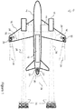
- FIG 1 shows a machine 10, in this example an aircraft, which comprises a fuel system 12 according to the present disclosure.
- the aircraft comprises a fuselage 14 from which wings 16 extend, with engines 18 mounted to the wings.
- engines 18 mounted to the wings.
- Other examples might involve alternative aircraft configurations, and different numbers of engines.
- the majority of the fuel system 12 is shown located in the fuselage 14. In alternative examples the fuel system 12 may be located elsewhere in the machine 10.
- Fuel pipes 19 fluidly connect the fuel system 12 and engines 18.
- the fuel system 12 comprises at least one vapour trail detection sensor 20.
- vapour trail detection sensors 20 are mounted towards the rear of the aircraft 10 facing aft. For example they are located at the tip of one or both wings 16 and/or at a trailing edge 22 of the fuselage.
- The, or each, vapour trail detection sensor 20 is mounted such that it has a field of view directed towards a vapour trail formation region. That is to say they are positioned such that they have a field of view 24 in a direction downstream of the vehicle 10, which in operation will offer a view of vapour trails 35 formed within the exhaust plumes 26 downstream of the engines 18.
- Each of the vapour trail detection sensors 20 is configured to generate a first signal 28 (shown as a dotted line) which indicates, for example, an optical depth (OD) of the young vapour trail 35.
- Each vapour trail detection sensor 20 is an optical device configured to deliver a signal indicative of the presence and/or properties of a vapour trail 35.
- a source of illumination 30 may also be provided on the aircraft and directed towards at least one region downstream of the engines 18 to illuminate at least part of the field of view 24 of the sensor 20.
- the sensor 20 is configured to detect electromagnetic radiation of at least one wavelength emitted and/or reflected by the vapour trail in response to energy emitted from the source of illumination 30.
- an emitter of sound (or ultrasonic) waves could be provided. The sensor would then be configured to detect the sound returned from the ice particles in the young contrail.
- the function of the vapour trail detection sensor would be performed by equipment remote to the aircraft, and the resulting information transmitted to the aircraft.
- equipment might include for example sensors mounted on the ground, on airships or balloons, on other aircraft, and/or on earth-orbiting satellites.
- the operation of the non-aircraft mounted vapour-trail detection sensors may optionally be enhanced by use of the aircraft-mounted source of illumination 30.
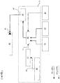
- Figure 2 shows a diagrammatic representation of the fuel system 12.
- the arrows with solid lines indicate the fuel flow communication path
- the arrows with dashed lines indicate signal communication routes.
- the fuel system 12 has a control unit 40 which is in signal communication with the or each vapour trail detection sensor(s) 20.
- a control unit 40 which is in signal communication with the or each vapour trail detection sensor(s) 20.
- the or each vapour trail detection sensor(s) 20 In Figure 2 only one vapour trail detection sensor 20 is shown. In alternative examples there may be more than one sensor 20.
- the control unit 40 is also in signal communication with at least a first fuel composition regulator 42 and a second fuel composition regulator 44.
- a third fuel composition regulator 46 is shown.
- the number of fuel composition regulators is dependent upon the number of fuel compositions the system is configured to operate with.
- Each fuel composition regulator 42,44,46 is in fluid communication with a source e.g. fuel tanks 48, 50, 52 of its respective fuel composition.
- the source of the first fuel composition is a first tank 48 for storage of a first fuel composition
- the source of the second fuel composition is a second tank 50 for storage of a second fuel composition.
- the source of the third fuel composition is a third tank 52 for storage of a third fuel composition.
- Further tanks are a source of the fuel composition that they are provided to contain.
- the tanks 48,50,52 are located on board the aircraft 10.
- the tanks 48, 50, 52 etc are fluidly isolated from one another. That is to say, the tanks 48, 50, 52 are not in fluid communication with each other, and there is no flow of fluid between them.
- the word "tank” is intended to mean an individual tank or a network of fluidly interconnected tanks, where each tank/network is fluidly isolated from the other respective tanks/networks.
- the fuel system 12 further comprises a fluid blender 54 in fluid communication with the tank 48 of the first fuel composition, the source 50 of the second fuel composition etc via the regulators 42,44,46.
- the blender 54 is configured to mix the first fuel composition, second fuel composition etc to produce a resultant fuel composition.
- the fluid blender 54 has at least one outlet 56 for delivering the resultant fuel composition to a fuel injection device 58 in the engine(s) 18.
- the fuel injection device 58 may be any type of fuel injector, for example a fuel nozzle, airspray injector, or plain orifice.
- the fuel injection device 58 may comprise one fuel injector, or a plurality of fuel injectors. Although in Figure 2 and Figure 3 only one fuel injector 58 is shown, each engine 18 may be fitted with a number of fuel injectors 58, each in fluid communication with the fuel blender 54.
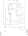
- FIG 3 shows a diagrammatic representation of an alternative example of the fuel system 12 according to the present disclosure.
- a regulator 42,44,46 for each fuel composition, there is a single regulator 60 which is in fluid communication with all of the fluid tanks 48,50,52.
- Such a regulator may thus comprise multiple inlets which are selectively openable and/or closable to control fuel flow therethrough from each, or a combination, of the fuel tanks 48, 50, 52.
- the control unit 40 comprises a blending ratio calculator 70 configured to calculate the required resultant fuel composition.
- the blending ratio calculator may comprise one or more processors arranged to receive a plurality of inputs and to determine a suitable control output for controlling operation of the regulator 60 of Figure 3 or else the regulators 42,44,46 shown in Figure 2 (and possibly the blender 54).
- the control unit 40 may comprise one or a plurality of communicating controllers/processors but will herein be referred to in the singular merely for simplicity.
- the control unit 40 is in signal communication with the vapour trail detection sensor 20. It is also in signal communication with one or more ambient temperature sensor 74. In some examples, the control unit 40 may be in signal communication with additional or alternative ambient condition sensors 75 for detecting (e.g. measuring) any of ambient pressure, ambient humidity and/or instantaneous actual values of soot emission index generated by the engine(s) 18. The control unit 40 is also optionally in signal communication with an array of sensors 76 or monitors for determining engine operating point.
- the engine operating point is defined by a collection of parameters, which may include the ambient conditions in which the engine is operating, comprising one or more engine operation parameter sensor, such as for example one or more sensor for measuring parameters such as fuel-flow rate, operating temperatures and/or pressures of the gas-flow or components at one or more locations on the engine, thrust produced by the engine, engine shaft rotational speed(s) and/or other parameters or settings indicative of the state of the engine.
- engine operation parameter sensor such as for example one or more sensor for measuring parameters such as fuel-flow rate, operating temperatures and/or pressures of the gas-flow or components at one or more locations on the engine, thrust produced by the engine, engine shaft rotational speed(s) and/or other parameters or settings indicative of the state of the engine.
- numeral 80 indicates a signal representative of the relative proportions of the different available fuels that should be present in the fuel composition to be supplied to the engines.
- the control signal 80 may define a blending ratio(s) or fuel-flow rates for each of the distinct fluid compositions.
- the blending ratio calculator could comprise a soot requirement generator comprising, or linked to, a look up table or database for determining the desired soot emission index.
- the look up table or database could thus comprise data relating to the dependency of vapour trail optical depth upon soot emission index at various ambient conditions.
- the soot requirement generator comprises a model and/or algorithm for direct calculation of the desired soot emission index.
- FIG. 5 there is shown a high level decision-making process for determining whether control steps are required to mitigate against contrail formation.
- the control system operates a primary loop to check whether the operating conditions (i.e. the ambient conditions and/or engine operation parameters) have changed materially since a previous iteration.
- the operating conditions could comprise any, or any combination of, ambient temperature, ambient pressure, ambient humidity, altitude, and/or engine throttle setting.
- This primary loop can be iterated without changing existing settings until a relevant change to operating conditions is determined.
- the controller determines whether the vapour trail detection sensor 20 (e.g. contrail optical depth (OD) sensor) is working correctly and is able to provide a signal indicative of the OD of any contrail which may form. If so, a usage policy may optionally be employed to determine whether it is deemed appropriate to use a method for controlling the fuel composition delivered to the engine according to the invention under the current operating conditions. For instance, it may or may not be considered appropriate to only use this invention when contrails persist, e.g. if ambient relative humidity over ice is 100% or greater. Additionally or alternatively, it may be deemed inappropriate to use the invention if engine operating conditions or external requirements restrict the available fuel compositions.
- the vapour trail detection sensor 20 e.g. contrail optical depth (OD) sensor
- OD optical depth
- the decision to use or not to use this invention to modify contrail properties may be informed by other factors such as the ambient temperature and/or the strength of incoming sunlight incident upon the formed contrail. For example, it may be deemed appropriate to attempt to ameliorate only contrails which are both persistent and existing primarily during the night-time. Such additional decision criteria would allow scarce and expensive biofuels to be targeted specifically at contrails with the highest climate-warming impact. Accordingly it is possible that an ambient condition sensor could comprise a light sensor.
- vapour trail detection sensor 20 e.g. contrail OD
- a pre-determined threshold value e.g. a suitable threshold value that lay well below the minimum likely contrail OD achievable through the operation of the invention, thus avoiding rapidly-cycling intermittent operation of the invention.
- a zero threshold could be used. In either example, the duration for which the threshold is exceeded may be taken into account and the fuel composition control scheme delayed accordingly.
- the current fuel composition is retained. If a material change in the operating conditions is detected but any of the other conditions described above are not satisfied, then a default fuel composition is used. For example in the absence of vapour trail formation, it may be desirable to use only one of the first or second fuel compositions, and hence the resultant fuel composition will simply be the first or second fuel composition. For example 100% kerosene may be delivered to the engines 18 via the fuel injectors 58, rather than a blend of kerosene and biofuel. Alternatively where the ambient conditions are such that vapour trails form but do not persist (i.e. in ambient air not super-saturated with respect to ice), the system could be operated or not operated, depending on the extent to which the occurrence of temporary vapour trails is considered desirable or not, and taking account of the available quantity of biofuel.
- a control scheme typically involving a search algorithm (or a simpler alternative where appropriate, as discussed below), is invoked to determine and implement the best fuel-composition for the prevailing conditions.
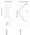
- soot EI trough-shaped dependency of contrail OD spanning a certain range of soot EI as shown in Figure 6A .
- the range of soot EI that can be achieved in practice is likely to be limited by a number of factors, such as: the engine's current operating point, including ambient conditions as well as absolute limits, technical, regulatory or commercial constraints on the range of possible useable fuel blends.
- the engine can beneficially be characterised as operating in one of a plurality of regimes for the purpose of the invention.
- Three broad regimes - regime A, regime B or regime C, illustrated in Figure 6 are used in this example although other subdivisions may be appropriate in alternative embodiments.
- Regimes A and C approximate a generally linear relationship (respectively descending and ascending) between contrail OD and soot EI.
- regimes A and/or C could each approximate another simple nonlinear mathematical relationship in which the gradient does not change sign (e.g. monotonically increasing or decreasing).
- Regime B assumes contrail OD will tend to a local or absolute minimum value for a given soot EI but will increase on either side thereof.
- Options for identification of the different regimes A, B and C include on-board computation, pre-populated lookup-table or database, or a decision-tree. Ambient temperature and soot EI could be used as the major contributing factors for determining the current regime.
- FIG. 7 there is shown the methodology or framework for altering the fuel blend delivered to the combustor by use of a search strategy. That is to say, the system may implement one or more attempts at a desired fuel blend and may monitor the impact on vapour trail formation in order to allow iteration towards an optimal final fuel composition for the current ambient/operating conditions.
- the search for the ideal fuel blend is therefore multi-dimensional.
- the sub-scenarios set out above concerning the dependency of soot EI upon LSP-fuel percentage within the blend may or may not be assessed.
- a search algorithm also known as a function optimisation algorithm or "optimiser" is used to explore the search space defined by various blending ratios of the individual fuel compositions.
- the search algorithm may also be applied as a default option, for example if it is not possible to rule out regime B with an adequate degree of certainty, e.g. if regime A or C cannot be determined, and/or if the ambient temperature sensor reading is defective, or if the relationship between contrail OD and soot EI is uncertain for any other reason at the given conditions.
- Other embodiments may not apply the steps of distinguishing between regimes and/or scenarios of operation, and may use a search algorithm in all cases.
- another embodiment may apply only a regime determination stage in order to allow identification of simple regimes for which a search algorithm is not required, i.e. in which an optimal fuel blend can be selected with certainty.
- a search algorithm allows the fuel blend to be varied in a controlled manner so as to determine the effect of the attempted fuel blend variation on contrail formation, e.g. by measuring contrail OD using sensor 20 or another characterising property of the contrail.
- the manner in which the fuel blend is varied and the resulting impact on the engine exhaust emissions is determined may be subject to various options.
- T the contrail lead-time
- the contrail lead-time limits the number of trial fuel compositions that can be explored per unit time, when using a search algorithm which waits for the results of a function evaluation before deciding what combination of parameter values to try next. Such delays are undesirable, particularly for aircraft travel velocities and so it is generally desirable to adopt a search algorithm or methodology which requires a minimum number of iterations or time delay to find an optimum fuel-blend.
- the pre-search may thus return an approximate range in which the fuel blend is optimal.
- a more accurate determination of the precise optimal fuel blend may then be run within the identified region, for example using a second/local search algorithm. In examples of the invention either one of the pre-search or second search algorithms may be used exclusively.
- the contrail lead-time is independent of fuel-blend ratio, and depends only upon the rate at which fuel is supplied to the engine, then it can be characterised with reasonable accuracy. This means that a measurement of contrail OD observed at any particular time t can be attributed to a fuel-blending ratio instruction in operation at time t - T
- One possible search algorithm may comprise, for example, Nelder & Mead's "downhill simplex” method, although other conventional or bespoke algorithms may prove suitable. Methods not requiring computation of the gradient of the fitness function may have an advantage in this application.
- a function optimisation algorithm or "optimiser"
- a search is performed for a final fuel composition which corresponds to substantially the minimum achievable contrail OD, given the current engine operating point and ambient conditions and any constraints imposed by the range of final fuel compositions which can be implemented in practice.
- a search is performed for a final fuel composition representing the most desirable balance between the cost of the final fuel composition and any avoided cost relating to the reduced optical depth of the contrail.
- any potential variations in additional charges, such as those related to carbon dioxide emissions, are also taken into account.
- One key characteristic of the pre-search phase described above is that the selection of points to be explored is determined 'a priori' and is not influenced by the values of contrail OD measured during the pre-search so as to avoid substantial time delays.
- each successive fuel blend ratio can be instructed while the consequences of the previous one are still propagating through the fuel system.
- a short holding time for discrete ratios attempted may be applied in order to help delineate between each condition to be sampled.
- the required duration of holding time may be predetermined based at least in part on the known contrail lead-time tolerance and/or any recorded variation in contrail lead-time over the course of a single flight, between flights, or between different aircraft of the same design.
- the holding time will be significantly smaller in magnitude than the contrail lead time.
- the rate of change of the fuel blend may be tailored to avoid the need for a holding time or else a shortened holding time may be applied at discrete intervals.
- a first step of the search may comprise a determination of a list of points (i.e. fuel blend ratios) to be explored within the search space. This can be done by evenly distributing a given number of points across an N-dimensional space. Another (although typically less efficient for two or higher search dimensions) approach would simply be to identify points lying on regular grid whose axes lie parallel to the axes of the search space.
- the above described approaches may be considered to enable a "pipeline” approach to characterising the particular relationship - applying specifically at the prevailing ambient conditions and engine operating point - between fuel-blend ratio and contrail OD.
- the pipeline approach can be implemented in a discrete or continuous mode.
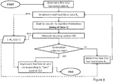
- Figure 8 illustrates an optimisation loop for detailed local search in which the delay T is incurred for each evaluation of a trial fuel-blend ratio, thereby requiring the outcome of one fuel blend ratio, Rn, to be determined before making a decision concerning the next trial fuel-blend ratio, Rn+1, to be attempted after ratio Rn. That is to say, the next trial fuel blend ratio is determined in dependence upon the results of the measurement of optical depth, ODn, corresponding to the previous or current ratio, Rn.
- control unit may implement either a pre-search or optimisation search algorithm selectively in dependence upon the magnitude in a change in ambient conditions or engine operating conditions.
- a sweep search may be avoided for only small changes in operating point.
- the search strategies according to examples of the invention allow a simple but robust method of determining an optimal fuel-blend ratio for varying operating conditions.
- the techniques described above rely on a relatively small set of input parameters, and so have fewer possible sensor-related failure modes, whilst also avoiding the need to have available wholly accurate models, algorithms, lookup-tables or databases concerning the relationship between soot emission index and contrail optical depth, or concerning the relationship between fuel-blend ratio and soot emission index.
- it can be employed in conjunction with the search techniques described above to identify cases in which a more efficient approach can be taken.
- the invention could react to changes in the fuels used or incorrect fuel loading, e.g. where there is uncertainty over the fuel compositions in each tank.
- optical soot emission index is the soot emission index which, if realised in practice under the prevailing ambient conditions, would lead to a minimisation of optical depth of the young contrail, and hence a minimisation of a young contrail's climate warming impact.
- the "optimal" soot emission index may correspond to the minimum achievable soot emission index given the available fuels and any constraints that may place limits on the blending ratios that may be employed.
- the "optimal" soot emission index may be higher than or lower than the minimum achievable soot emission index.
- the first fuel composition may have an aromatic and/or other non-paraffinic content substantially higher than that of the second fuel composition.
- the first fuel composition is Kerosene.
- the second fuel composition is a biofuel.
- the second fuel composition may be a low-soot-producing (LSP) or alternatively a low-sulphur, low-soot-producing (LSLSP) fuel.
- LSP low-soot-producing
- LSLSP low-sulphur, low-soot-producing
- the second fuel may be a blend of several such LSP and/or LSLSP fuels whose physical and chemical properties make it suitable for use in an engine with the first fuel composition, for example as an aviation fuel when blended with conventional kerosene.
- Examples include (but are not limited to) coal-to-liquids (CTL), gas-to-liquids(GTL), biomass-to-liquids (BTL), synthetic paraffinic kerosene (SPK), hydrotreated renewable jet-fuel (HRJ), alcohol-to-jet, and Hydro-processed Esters and Fatty Acids (HEFA).
- CTL coal-to-liquids
- GTL gas-to-liquids
- BTL biomass-to-liquids
- SPK synthetic paraffinic kerosene
- HRJ hydrotreated renewable jet-fuel
- alcohol-to-jet Hydro-processed Esters and Fatty Acids
- the second fuel composition could be liquefied natural gas (LNG) or hydrogen.
- LNG liquefied natural gas
- the first and second fuel compositions may require separate injection mechanisms into the engine, and so blending or mixing may not take place prior to injection into the engine, but may instead occur for example within the turbulent environment of the engine's combustion chamber.
- the system 12 is operable to blend fuel, or to simply deliver one of the stored fuel compositions. That is to say the action of blending together two or more fuels may optionally be employed or not employed according to policy decision taking account of ambient conditions and engine operating point.
- the resultant fuel composition may comprise any proportion of first fuel composition and second fuel composition in the range from 0% to 100%.
- the resultant fuel composition may comprise x% of the first fuel composition and (100-x)% of the second fuel composition, where x has a value anywhere in the range from 0 to 100.
- the resultant fuel composition may comprise 0% of the first fuel composition and 100% of the second fuel composition.
- the resultant fuel composition may comprise 100% of the first fuel composition and 0% of the second fuel composition.
- the control unit 40 may determine which of a default fuel composition and a composition which may enable the optical depth of the vapour trail to be reduced is employed. This determination may be based on the determined likelihood of contrail formation and/or persistence, and taking into account an operational policy specifying the conditions under which vapour trail optical-depth modification should be attempted.
- this invention incurs very little weight penalty and it also requires very low energy to operate. Furthermore the invention does not interfere with engine operating point and does not introduce a significant fuel-efficiency penalty or present lifing issues for the engine to be able to accommodate contrail reduction. Also the invention could reduce and/or avoid the need to navigate around regions of ice-supersaturated air, thereby avoiding fuel burn penalties and allowing aircraft to adopt an optimal cruise trajectory while still benefitting from a material reduction in overall climate impact.
- a controller may determine a difference in specific energy between the current and new/proposed fuel compositions. If a difference is determined, the controller may output control instructions to adjust the flow rate of the proposed/new fuel composition, e.g. relative to the current composition flow rate, when delivered to the engine to maintain the same rate of fuel energy input to the engine.
- the same level of thrust can be delivered by the engine despite the change in fuel composition being supplied.
- the changes in specific energy by use of the invention are envisaged to be relatively small, such a check may be important in assuring safety and predictable ongoing engine operation. Accordingly such a feature may be generally applicable to any of the embodiments described above.
Landscapes
- Engineering & Computer Science (AREA)
- Chemical & Material Sciences (AREA)
- Combustion & Propulsion (AREA)
- General Engineering & Computer Science (AREA)
- Mechanical Engineering (AREA)
- Analytical Chemistry (AREA)
- General Health & Medical Sciences (AREA)
- General Physics & Mathematics (AREA)
- Immunology (AREA)
- Pathology (AREA)
- Biochemistry (AREA)
- Physics & Mathematics (AREA)
- Life Sciences & Earth Sciences (AREA)
- Health & Medical Sciences (AREA)
- Combined Controls Of Internal Combustion Engines (AREA)
- Output Control And Ontrol Of Special Type Engine (AREA)
Claims (15)
- Treibstoffzufuhrsystem für ein Triebwerk, wobei das System Folgendes umfasst:einen Kondensstreifenerkennungssensor (20), der zum Generieren eines Erkennungssignals ausgelegt ist, welches auf ein Charakteristikum eines Kondensstreifens hinweist;einen Regulator (42, 44, 46, 60), der zum Regulieren eines Volumens einer ersten und einer zweiten Treibstoffzusammensetzung ausgelegt ist, die dem Triebwerk als resultierende Treibstoffzusammensetzung zugeführt wird; und eine Steuerung (40), angeordnet zum Vornehmen einer Suche nach Probetreibstoffzusammensetzungen, indem der Regulator derart gesteuert wird, dass dem Triebwerk eine Vielzahl von Probetreibstoffzusammensetzungen mit verschiedenen Verhältnissen zwischen den ersten und zweiten Treibstoffzusammensetzungen zugeführt werden, und zum Steuern der Zufuhr einer resultierenden Treibstoffzusammensetzung zu dem Triebwerk als Reaktion auf die Kondensstreifen-Charakteristikum-Erkennungssignale für die Vielzahl von Probetreibstoffzusammensetzungen; wobei die Suche eine erste Grobsuche zur Identifizierung eines Teilbereichs oder Punkts, für welchen ein wünschenswerter Wert des Kondensstreifen-Charakteristikums erfasst wird, und eine zweite Suche, die eine optimale finale Treibstoffzusammensetzung in der Nähe des Teilbereichs oder Punktes identifiziert, umfasst.
- Treibstoffzufuhrsystem nach Anspruch 1, wobei die Steuerung einen Suchalgorithmus umfasst, der zum Durchführen einer Durchsuchung eines Bereichs von Treibstoffzusammensetzungs-Verhältnissen bei der Erkennung einer Veränderung von einer oder mehreren Triebwerk-Betriebsbedingung und/oder Umgebungsbedingung angeordnet ist.
- Treibstoffzufuhrsystem nach Anspruch 2, wobei die Umgebungsbedingung das erfasste Kondensstreifen-Charakteristikum und/oder die Umgebungstemperatur oder -feuchtigkeit umfasst.
- Treibstoffzufuhrsystem nach Anspruch 2 oder 3, wobei die Durchsuchung eine Durchsuchung einer Vielzahl einzelner Treibstoffzusammensetzungs-Verhältnisse über den Bereich hinweg umfasst.
- Treibstoffzufuhrsystem nach einem der vorhergehenden Ansprüche, wobei die zweite Suche iterativ ist, wobei jede Iteration eines Probetreibstoffzusammensetzungs-Verhältnisses von einem Kondensstreifen-Erkennungs-Sensorsignal abhängig ist, das einem oder mehreren vorherigen Probetreibstoffzusammensetzungs-Verhältnissen entspricht.
- Treibstoffzufuhrsystem nach einem der vorhergehenden Ansprüche, wobei zusätzlich zu der Suche die Steuerung zum Bezugnehmen auf ein vorgegebenes Datenfeld wie etwa eine Datenbank, eine Nachschlagetabelle, einen Entscheidungsbaum oder Algorithmus beim Bestimmen der resultierenden Treibstoffzusammensetzung für die Zufuhr zu dem Triebwerk angeordnet ist.
- Treibstoffzufuhrsystem nach einem der vorhergehenden Ansprüche, wobei das System einen oder mehrere Umgebungsbedingungssensor und/oder Triebwerk-Betriebssensor umfasst und die Steuerung zum Identifizieren eines Triebwerk-Betriebszustands zumindest teilweise auf Grundlage der Sensorablesungen angeordnet ist.
- Treibstoffzufuhrsystem nach Anspruch 7, wobei eine Vielzahl von Betriebszuständen definiert ist, von denen jeder ein anderes vorgegebenes Verhältnis zwischen dem Kondensstreifen-Charakteristikum und einem erfassten Parameter aufweist, wobei die Steuerung bestimmt, ob die Suche auf Grundlage der Zustandsbestimmung durchzuführen ist oder nicht.
- Treibstoffzufuhrsystem nach Anspruch 8, wobei der Triebwerks-Betriebsparameter den Rußemissionsindex umfasst.
- Treibstoffzufuhrsystem nach einem der vorhergehenden Ansprüche, wobei die Steuerung ein finales Treibstoffzusammensetzungs-Verhältnis auswählt, um die optische Tiefe des Kondensstreifens zu minimieren.
- Treibstoffzufuhrsystem nach einem der vorhergehenden Ansprüche, ferner umfassend erste und zweite Treibstoffbehälter, wobei jeder Behälter von den anderen fluid-isoliert ist, wobei der erste Treibstoffbehälter die erste Treibstoffzusammensetzung enthält und der zweite Treibstoffbehälter die zweite Treibstoffzusammensetzung enthält, wobei jeder Behälter mit einem verbundenen Regulator zum Steuern der Zufuhr des jeweiligen Treibstoffs an das Triebwerk versehen ist.
- Treibstoffzufuhrsystem nach einem der vorhergehenden Ansprüche, wobei der Regulator einen Treibstoffmischer umfasst, der zum Empfangen der ersten und zweiten Treibstoffzusammensetzungen und zum Abgeben der finalen Treibstoffzusammensetzung, welche ein im Wesentlichen homogenes Gemisch der ersten und zweiten Treibstoffzusammensetzungen umfasst, an das Triebwerk angeordnet ist.
- Luftfahrzeug, umfassend ein Treibstoffzufuhrsystem nach einem der vorhergehenden Ansprüche.
- Treibstoffzufuhrverfahren für ein Triebwerk, umfassend:Empfangen eines Kondensstreifen-Erkennungssignals, das auf ein Charakteristikum eines durch das Triebwerk erzeugten Kondensstreifens hinweist;Regulieren eines Volumens einer ersten und einer zweiten Treibstoffzusammensetzung, welche dem Triebwerk als resultierende Treibstoffzusammensetzung zugeführt wird; undVornehmen einer Suche nach Probetreibstoffzusammensetzungen durch Steuern der Zufuhr einer Vielzahl von Probetreibstoffzusammensetzungen mit verschiedenen Verhältnissen der ersten und zweiten Treibstoffzusammensetzungen an das Triebwerk, wobei die Suche eine erste Grobsuche zur Identifizierung eines Teilbereichs oder Punkts, für welchen ein wünschenswerter Wert des Kondensstreifen-Charakteristikums erfasst wird, und eine zweite Suche, die eine optimale finale Treibstoffzusammensetzung in der Nähe des Teilbereichs oder Punktes identifiziert, umfasst; undSteuern der Zufuhr einer resultierenden Treibstoffzusammensetzung an das Triebwerk als Reaktion auf die Kondensstreifen-Charakteristikum-Erkennungssignale für die Vielzahl von Probetreibstoffzusammensetzungen.
- Datenträger, umfassend Maschinen-lesbare Anweisungen für den Betrieb einer Triebwerktreibstoffsystemsteuerung zum Steuern der Zufuhr von ersten und zweiten Treibstoffzusammensetzungen an ein Triebwerk durch:Empfangen einer Signalausgabe eines Kondensstreifen-Erkennungssensors und zum Bestimmen des Vorhandenseins oder Nichtvorhandenseins eines Kondensstreifens, der durch eine Triebwerkabgasströmung verursacht wird; bei Erkennung eines KondensstreifensVornehmen einer Suche nach Probetreibstoffzusammensetzungen mit verschiedenen Verhältnissen der ersten und zweiten Treibstoffzusammensetzungen durch Steuern der Zufuhr der Probetreibstoffzusammensetzungen an das Triebwerk, wobei die Suche eine erste Grobsuche zum Identifizieren eines Teilbereichs oder Punktes, für den ein wünschenswerter Wert des Kondensstreifens-Charakteristikums erfasst wird, und eine zweite Suche, welche eine optimale finale Treibstoffzusammensetzung in der Nähe des Teilbereichs oder Punktes identifiziert, umfasst;Steuern der Zufuhr einer resultierenden Treibstoffzusammensetzung an das Triebwerk als Reaktion auf die Kondensstreifen-Charakteristikum-Erkennungssignale für die Vielzahl von Probetreibstoffzusammensetzungen.
Applications Claiming Priority (1)
| Application Number | Priority Date | Filing Date | Title |
|---|---|---|---|
| GBGB1317731.6A GB201317731D0 (en) | 2013-10-08 | 2013-10-08 | Fuel delivery system |
Publications (2)
| Publication Number | Publication Date |
|---|---|
| EP2860374A1 EP2860374A1 (de) | 2015-04-15 |
| EP2860374B1 true EP2860374B1 (de) | 2017-06-14 |
Family
ID=49630316
Family Applications (1)
| Application Number | Title | Priority Date | Filing Date |
|---|---|---|---|
| EP14184757.4A Active EP2860374B1 (de) | 2013-10-08 | 2014-09-15 | Brennstoffzuführsystem |
Country Status (3)
| Country | Link |
|---|---|
| US (1) | US9309811B2 (de) |
| EP (1) | EP2860374B1 (de) |
| GB (1) | GB201317731D0 (de) |
Families Citing this family (26)
| Publication number | Priority date | Publication date | Assignee | Title |
|---|---|---|---|---|
| GB2524775B (en) * | 2014-04-02 | 2017-11-15 | Rolls Royce Plc | Aircraft vapour trail control system |
| GB201405894D0 (en) * | 2014-04-02 | 2014-05-14 | Rolls Royce Plc | Aircraft vapour trail control system |
| US10018158B2 (en) * | 2016-06-10 | 2018-07-10 | Ford Global Technologies, Llc | Evaporative emissions testing based on ambient light amount |
| US11761378B2 (en) | 2019-05-13 | 2023-09-19 | Rolls-Royce Corporation | Bleed air charged cooling system with turbo-generator |
| US11015476B2 (en) * | 2019-05-13 | 2021-05-25 | Rolls-Royce Corporation | Electrical energy generating system |
| GB2587669A (en) * | 2019-10-02 | 2021-04-07 | Advanced Mobility Res And Development Ltd | Systems and methods for aircraft |
| EP3875742A1 (de) * | 2020-03-04 | 2021-09-08 | Rolls-Royce plc | Gestufte verbrennung |
| FR3108174A1 (fr) * | 2020-03-11 | 2021-09-17 | Airbus | Système d’échantillonnage et d’analyse de traînée de condensation générée par un aéronef. |
| EP3961012B1 (de) * | 2020-09-01 | 2024-04-10 | Airbus Operations, S.L.U. | Vorrichtung und verfahren zur beurteilung von flugzeugflugkondensstreifen |
| GB202104469D0 (en) * | 2021-03-30 | 2021-05-12 | Rolls Royce Plc | Aircraft propulsion system |
| US12486812B2 (en) * | 2021-09-22 | 2025-12-02 | Bedrock Ventures LLC | Standby fuel storage system for uninterrupted operation during primary fuel curtailment |
| US11885270B2 (en) * | 2021-09-22 | 2024-01-30 | Michael D. Mercer | Energy utilization system |
| GB2616822A (en) | 2021-12-21 | 2023-09-27 | Rolls Royce Plc | Determination of fuel characteristics |
| US11708769B2 (en) | 2021-12-21 | 2023-07-25 | Rolls-Royce Plc | Exhaust content |
| US11708796B2 (en) | 2021-12-21 | 2023-07-25 | Rolls-Royce Plc | Performance parameters |
| GB2614435B (en) * | 2021-12-21 | 2024-05-15 | Rolls Royce Plc | Determination of fuel characteristics |
| GB202205347D0 (en) | 2022-04-12 | 2022-05-25 | Rolls Royce Plc | Propulsion system |
| GB202205354D0 (en) * | 2022-04-12 | 2022-05-25 | Rolls Royce Plc | Fuel delivery |
| GB202205355D0 (en) | 2022-04-12 | 2022-05-25 | Rolls Royce Plc | Gas turbine operation |
| US12366211B2 (en) * | 2022-08-09 | 2025-07-22 | Pratt & Whitney Canada Corp. | Aircraft contrail monitoring and targeted mitigation |
| US20240167426A1 (en) * | 2022-11-21 | 2024-05-23 | Rosemount Aerospace Inc. | Contrail detection, discrimination, and control |
| GB202219391D0 (en) | 2022-12-21 | 2023-02-01 | Rolls Royce Plc | Fuel oil heat exchange |
| GB202219390D0 (en) * | 2022-12-21 | 2023-02-01 | Rolls Royce Plc | Gas turbine operation |
| US12221222B2 (en) * | 2023-05-26 | 2025-02-11 | Hamilton Sundstrand Corporation | Cooling fluid used as secondary fuel source |
| EP4477854A1 (de) * | 2023-06-16 | 2024-12-18 | Rolls-Royce plc | Kraftstoffsystem |
| GB2636970A (en) | 2023-11-28 | 2025-07-09 | Airbus Operations Ltd | Controlling supply of aircraft engine with multiple fuels |
Family Cites Families (27)
| Publication number | Priority date | Publication date | Assignee | Title |
|---|---|---|---|---|
| US3517505A (en) | 1962-11-13 | 1970-06-30 | Us Air Force | Method and apparatus for suppressing contrails |
| US3289409A (en) | 1964-07-13 | 1966-12-06 | Phillips Petroleum Co | Hiding condensation trails from high altitude aircraft |
| US3517512A (en) | 1965-02-02 | 1970-06-30 | Us Air Force | Apparatus for suppressing contrails |
| US4766725A (en) | 1985-12-24 | 1988-08-30 | Scipar, Inc. | Method of suppressing formation of contrails and solution therefor |
| US5005355A (en) | 1988-08-24 | 1991-04-09 | Scipar, Inc. | Method of suppressing formation of contrails and solution therefor |
| WO2001086127A2 (en) * | 2000-05-08 | 2001-11-15 | Cummins, Inc. | Internal combustion engine operable in pcci mode with post-ignition injection and method of operation |
| US6908702B2 (en) * | 2002-05-03 | 2005-06-21 | Ion America Corporation | Fuel cell for airship power generation and heating |
| US6854688B2 (en) * | 2002-05-03 | 2005-02-15 | Ion America Corporation | Solid oxide regenerative fuel cell for airplane power generation and storage |
| EP1763631A2 (de) * | 2004-07-02 | 2007-03-21 | Toyota Jidosha Kabushiki Kaisha | Kraftstoffzufuhrsystem für verbrennungsmotor |
| WO2007061903A1 (en) | 2005-11-17 | 2007-05-31 | Cps Biofuels, Inc. | Alternative fuel and fuel additive compositions |
| GB0608859D0 (en) | 2006-05-05 | 2006-06-14 | Rolls Royce Plc | A gas turbine engine |
| US8403661B2 (en) * | 2007-03-09 | 2013-03-26 | Coprecitec, S.L. | Dual fuel heater |
| GB0710153D0 (en) | 2007-05-26 | 2007-07-04 | Rolls Royce Plc | Method and apparatus for suppressing aeroengine contrails |
| GB0710162D0 (en) | 2007-05-26 | 2007-07-04 | Rolls Royce Plc | Method and apparatus for suppressing aeroengine contrails |
| JP4689642B2 (ja) * | 2007-05-30 | 2011-05-25 | 愛三工業株式会社 | 燃料供給装置 |
| US20100252648A1 (en) * | 2007-08-21 | 2010-10-07 | Nicholas Paul Robinson | Climate Processor |
| US20100122519A1 (en) | 2008-11-14 | 2010-05-20 | Alan Epstein | Ultra-low sulfur fuel and method for reduced contrail formation |
| US9354618B2 (en) | 2009-05-08 | 2016-05-31 | Gas Turbine Efficiency Sweden Ab | Automated tuning of multiple fuel gas turbine combustion systems |
| US8214129B2 (en) * | 2009-05-13 | 2012-07-03 | Ford Global Technologies, Llc | Distinguishing the fuel admitted to a fuel system |
| DE102009041190B4 (de) | 2009-09-14 | 2012-04-19 | Deutsches Zentrum für Luft- und Raumfahrt e.V. | Vorrichtung und Verfahren zur Ermittlung und Anzeige klimarelevanter Wirkungen eines von einem Flugzeug erzeugten Kondensstreifen |
| US20110225947A1 (en) * | 2010-03-17 | 2011-09-22 | Benjamin Paul Lacy | System and methods for altering air flow in a combustor |
| JP2012142120A (ja) * | 2010-12-28 | 2012-07-26 | Jx Nippon Oil & Energy Corp | 燃料電池システム |
| CN104246492A (zh) * | 2012-03-19 | 2014-12-24 | 吉坤日矿日石能源株式会社 | 气体燃料的组分判别方法、气体燃料的组分判别装置、燃料供应系统以及燃料电池系统 |
| GB201211058D0 (en) * | 2012-06-22 | 2012-08-01 | Rolls Royce Plc | Fuel system |
| GB201211064D0 (en) | 2012-06-22 | 2012-08-01 | Rolls Royce Plc | Fuel system |
| GB201211061D0 (en) | 2012-06-22 | 2012-08-01 | Rolls Royce Plc | Fuel delivery system |
| CN102926874B (zh) | 2012-11-07 | 2014-08-27 | 中国科学院工程热物理研究所 | 一种燃料灵活混用及切换的燃气轮机燃料供应装置及控制方法 |
-
2013
- 2013-10-08 GB GBGB1317731.6A patent/GB201317731D0/en not_active Ceased
-
2014
- 2014-09-15 EP EP14184757.4A patent/EP2860374B1/de active Active
- 2014-09-15 US US14/486,337 patent/US9309811B2/en active Active
Non-Patent Citations (1)
| Title |
|---|
| None * |
Also Published As
| Publication number | Publication date |
|---|---|
| EP2860374A1 (de) | 2015-04-15 |
| GB201317731D0 (en) | 2013-11-20 |
| US20150100219A1 (en) | 2015-04-09 |
| US9309811B2 (en) | 2016-04-12 |
Similar Documents
| Publication | Publication Date | Title |
|---|---|---|
| EP2860374B1 (de) | Brennstoffzuführsystem | |
| US9518965B2 (en) | Fuel system | |
| US9146566B2 (en) | Fuel system | |
| US9650968B2 (en) | Aircraft engine fuel system | |
| US11821373B2 (en) | Staged combustion | |
| US9440746B2 (en) | Aircraft vapour trail control system | |
| US9399521B2 (en) | Aircraft vapour trail control system | |
| EP2112572B1 (de) | Verfahren und System zum Betreiben von Gasturbinenmotorsystemen | |
| US4903478A (en) | Dual manifold fuel system | |
| US20160146117A1 (en) | Aircraft engine fuel system | |
| EP2677139B1 (de) | Brennstoffzufuhrsystem | |
| EP2873836B1 (de) | Motorkraftstoffzufuhrsystem | |
| US12241409B2 (en) | Aircraft propulsion system | |
| Yixuan et al. | Efficiency optimized fuel supply strategy of aircraft engine based on air-fuel ratio control | |
| EP4477854A1 (de) | Kraftstoffsystem | |
| Vera-Morales et al. | Modeling performance and emissions from aircraft in the aviation integrated modelling project | |
| Szedlmayer et al. | Combustion and Performance Sensitivity to Fuel Cetane Number in an Aviation Diesel Engine | |
| Turan et al. | Effects of fuel consumption of commercial turbofans on global warming |
Legal Events
| Date | Code | Title | Description |
|---|---|---|---|
| PUAI | Public reference made under article 153(3) epc to a published international application that has entered the european phase |
Free format text: ORIGINAL CODE: 0009012 |
|
| 17P | Request for examination filed |
Effective date: 20140915 |
|
| AK | Designated contracting states |
Kind code of ref document: A1 Designated state(s): AL AT BE BG CH CY CZ DE DK EE ES FI FR GB GR HR HU IE IS IT LI LT LU LV MC MK MT NL NO PL PT RO RS SE SI SK SM TR |
|
| AX | Request for extension of the european patent |
Extension state: BA ME |
|
| RAP1 | Party data changed (applicant data changed or rights of an application transferred) |
Owner name: ROLLS-ROYCE PLC |
|
| R17P | Request for examination filed (corrected) |
Effective date: 20151009 |
|
| RBV | Designated contracting states (corrected) |
Designated state(s): AL AT BE BG CH CY CZ DE DK EE ES FI FR GB GR HR HU IE IS IT LI LT LU LV MC MK MT NL NO PL PT RO RS SE SI SK SM TR |
|
| GRAP | Despatch of communication of intention to grant a patent |
Free format text: ORIGINAL CODE: EPIDOSNIGR1 |
|
| STAA | Information on the status of an ep patent application or granted ep patent |
Free format text: STATUS: GRANT OF PATENT IS INTENDED |
|
| INTG | Intention to grant announced |
Effective date: 20170306 |
|
| GRAS | Grant fee paid |
Free format text: ORIGINAL CODE: EPIDOSNIGR3 |
|
| GRAA | (expected) grant |
Free format text: ORIGINAL CODE: 0009210 |
|
| STAA | Information on the status of an ep patent application or granted ep patent |
Free format text: STATUS: THE PATENT HAS BEEN GRANTED |
|
| AK | Designated contracting states |
Kind code of ref document: B1 Designated state(s): AL AT BE BG CH CY CZ DE DK EE ES FI FR GB GR HR HU IE IS IT LI LT LU LV MC MK MT NL NO PL PT RO RS SE SI SK SM TR |
|
| REG | Reference to a national code |
Ref country code: GB Ref legal event code: FG4D |
|
| REG | Reference to a national code |
Ref country code: CH Ref legal event code: EP Ref country code: AT Ref legal event code: REF Ref document number: 901200 Country of ref document: AT Kind code of ref document: T Effective date: 20170615 |
|
| REG | Reference to a national code |
Ref country code: IE Ref legal event code: FG4D |
|
| REG | Reference to a national code |
Ref country code: DE Ref legal event code: R096 Ref document number: 602014010693 Country of ref document: DE |
|
| REG | Reference to a national code |
Ref country code: FR Ref legal event code: PLFP Year of fee payment: 4 |
|
| REG | Reference to a national code |
Ref country code: NL Ref legal event code: MP Effective date: 20170614 |
|
| REG | Reference to a national code |
Ref country code: LT Ref legal event code: MG4D |
|
| PG25 | Lapsed in a contracting state [announced via postgrant information from national office to epo] |
Ref country code: LT Free format text: LAPSE BECAUSE OF FAILURE TO SUBMIT A TRANSLATION OF THE DESCRIPTION OR TO PAY THE FEE WITHIN THE PRESCRIBED TIME-LIMIT Effective date: 20170614 Ref country code: FI Free format text: LAPSE BECAUSE OF FAILURE TO SUBMIT A TRANSLATION OF THE DESCRIPTION OR TO PAY THE FEE WITHIN THE PRESCRIBED TIME-LIMIT Effective date: 20170614 Ref country code: NO Free format text: LAPSE BECAUSE OF FAILURE TO SUBMIT A TRANSLATION OF THE DESCRIPTION OR TO PAY THE FEE WITHIN THE PRESCRIBED TIME-LIMIT Effective date: 20170914 Ref country code: GR Free format text: LAPSE BECAUSE OF FAILURE TO SUBMIT A TRANSLATION OF THE DESCRIPTION OR TO PAY THE FEE WITHIN THE PRESCRIBED TIME-LIMIT Effective date: 20170915 Ref country code: HR Free format text: LAPSE BECAUSE OF FAILURE TO SUBMIT A TRANSLATION OF THE DESCRIPTION OR TO PAY THE FEE WITHIN THE PRESCRIBED TIME-LIMIT Effective date: 20170614 |
|
| REG | Reference to a national code |
Ref country code: AT Ref legal event code: MK05 Ref document number: 901200 Country of ref document: AT Kind code of ref document: T Effective date: 20170614 |
|
| PG25 | Lapsed in a contracting state [announced via postgrant information from national office to epo] |
Ref country code: BG Free format text: LAPSE BECAUSE OF FAILURE TO SUBMIT A TRANSLATION OF THE DESCRIPTION OR TO PAY THE FEE WITHIN THE PRESCRIBED TIME-LIMIT Effective date: 20170914 Ref country code: RS Free format text: LAPSE BECAUSE OF FAILURE TO SUBMIT A TRANSLATION OF THE DESCRIPTION OR TO PAY THE FEE WITHIN THE PRESCRIBED TIME-LIMIT Effective date: 20170614 Ref country code: LV Free format text: LAPSE BECAUSE OF FAILURE TO SUBMIT A TRANSLATION OF THE DESCRIPTION OR TO PAY THE FEE WITHIN THE PRESCRIBED TIME-LIMIT Effective date: 20170614 Ref country code: NL Free format text: LAPSE BECAUSE OF FAILURE TO SUBMIT A TRANSLATION OF THE DESCRIPTION OR TO PAY THE FEE WITHIN THE PRESCRIBED TIME-LIMIT Effective date: 20170614 Ref country code: SE Free format text: LAPSE BECAUSE OF FAILURE TO SUBMIT A TRANSLATION OF THE DESCRIPTION OR TO PAY THE FEE WITHIN THE PRESCRIBED TIME-LIMIT Effective date: 20170614 |
|
| PG25 | Lapsed in a contracting state [announced via postgrant information from national office to epo] |
Ref country code: EE Free format text: LAPSE BECAUSE OF FAILURE TO SUBMIT A TRANSLATION OF THE DESCRIPTION OR TO PAY THE FEE WITHIN THE PRESCRIBED TIME-LIMIT Effective date: 20170614 Ref country code: RO Free format text: LAPSE BECAUSE OF FAILURE TO SUBMIT A TRANSLATION OF THE DESCRIPTION OR TO PAY THE FEE WITHIN THE PRESCRIBED TIME-LIMIT Effective date: 20170614 Ref country code: AT Free format text: LAPSE BECAUSE OF FAILURE TO SUBMIT A TRANSLATION OF THE DESCRIPTION OR TO PAY THE FEE WITHIN THE PRESCRIBED TIME-LIMIT Effective date: 20170614 Ref country code: CZ Free format text: LAPSE BECAUSE OF FAILURE TO SUBMIT A TRANSLATION OF THE DESCRIPTION OR TO PAY THE FEE WITHIN THE PRESCRIBED TIME-LIMIT Effective date: 20170614 Ref country code: SK Free format text: LAPSE BECAUSE OF FAILURE TO SUBMIT A TRANSLATION OF THE DESCRIPTION OR TO PAY THE FEE WITHIN THE PRESCRIBED TIME-LIMIT Effective date: 20170614 |
|
| PG25 | Lapsed in a contracting state [announced via postgrant information from national office to epo] |
Ref country code: IT Free format text: LAPSE BECAUSE OF FAILURE TO SUBMIT A TRANSLATION OF THE DESCRIPTION OR TO PAY THE FEE WITHIN THE PRESCRIBED TIME-LIMIT Effective date: 20170614 Ref country code: IS Free format text: LAPSE BECAUSE OF FAILURE TO SUBMIT A TRANSLATION OF THE DESCRIPTION OR TO PAY THE FEE WITHIN THE PRESCRIBED TIME-LIMIT Effective date: 20171014 Ref country code: PL Free format text: LAPSE BECAUSE OF FAILURE TO SUBMIT A TRANSLATION OF THE DESCRIPTION OR TO PAY THE FEE WITHIN THE PRESCRIBED TIME-LIMIT Effective date: 20170614 Ref country code: ES Free format text: LAPSE BECAUSE OF FAILURE TO SUBMIT A TRANSLATION OF THE DESCRIPTION OR TO PAY THE FEE WITHIN THE PRESCRIBED TIME-LIMIT Effective date: 20170614 Ref country code: SM Free format text: LAPSE BECAUSE OF FAILURE TO SUBMIT A TRANSLATION OF THE DESCRIPTION OR TO PAY THE FEE WITHIN THE PRESCRIBED TIME-LIMIT Effective date: 20170614 |
|
| REG | Reference to a national code |
Ref country code: DE Ref legal event code: R097 Ref document number: 602014010693 Country of ref document: DE |
|
| PLBE | No opposition filed within time limit |
Free format text: ORIGINAL CODE: 0009261 |
|
| STAA | Information on the status of an ep patent application or granted ep patent |
Free format text: STATUS: NO OPPOSITION FILED WITHIN TIME LIMIT |
|
| PG25 | Lapsed in a contracting state [announced via postgrant information from national office to epo] |
Ref country code: DK Free format text: LAPSE BECAUSE OF FAILURE TO SUBMIT A TRANSLATION OF THE DESCRIPTION OR TO PAY THE FEE WITHIN THE PRESCRIBED TIME-LIMIT Effective date: 20170614 |
|
| REG | Reference to a national code |
Ref country code: CH Ref legal event code: PL |
|
| 26N | No opposition filed |
Effective date: 20180315 |
|
| PG25 | Lapsed in a contracting state [announced via postgrant information from national office to epo] |
Ref country code: MC Free format text: LAPSE BECAUSE OF FAILURE TO SUBMIT A TRANSLATION OF THE DESCRIPTION OR TO PAY THE FEE WITHIN THE PRESCRIBED TIME-LIMIT Effective date: 20170614 |
|
| REG | Reference to a national code |
Ref country code: IE Ref legal event code: MM4A |
|
| REG | Reference to a national code |
Ref country code: BE Ref legal event code: MM Effective date: 20170930 |
|
| PG25 | Lapsed in a contracting state [announced via postgrant information from national office to epo] |
Ref country code: LU Free format text: LAPSE BECAUSE OF NON-PAYMENT OF DUE FEES Effective date: 20170915 |
|
| PG25 | Lapsed in a contracting state [announced via postgrant information from national office to epo] |
Ref country code: CH Free format text: LAPSE BECAUSE OF NON-PAYMENT OF DUE FEES Effective date: 20170930 Ref country code: IE Free format text: LAPSE BECAUSE OF NON-PAYMENT OF DUE FEES Effective date: 20170915 Ref country code: LI Free format text: LAPSE BECAUSE OF NON-PAYMENT OF DUE FEES Effective date: 20170930 |
|
| PG25 | Lapsed in a contracting state [announced via postgrant information from national office to epo] |
Ref country code: BE Free format text: LAPSE BECAUSE OF NON-PAYMENT OF DUE FEES Effective date: 20170930 Ref country code: SI Free format text: LAPSE BECAUSE OF FAILURE TO SUBMIT A TRANSLATION OF THE DESCRIPTION OR TO PAY THE FEE WITHIN THE PRESCRIBED TIME-LIMIT Effective date: 20170614 |
|
| REG | Reference to a national code |
Ref country code: FR Ref legal event code: PLFP Year of fee payment: 5 |
|
| PG25 | Lapsed in a contracting state [announced via postgrant information from national office to epo] |
Ref country code: MT Free format text: LAPSE BECAUSE OF NON-PAYMENT OF DUE FEES Effective date: 20170915 |
|
| PG25 | Lapsed in a contracting state [announced via postgrant information from national office to epo] |
Ref country code: HU Free format text: LAPSE BECAUSE OF FAILURE TO SUBMIT A TRANSLATION OF THE DESCRIPTION OR TO PAY THE FEE WITHIN THE PRESCRIBED TIME-LIMIT; INVALID AB INITIO Effective date: 20140915 |
|
| PG25 | Lapsed in a contracting state [announced via postgrant information from national office to epo] |
Ref country code: CY Free format text: LAPSE BECAUSE OF FAILURE TO SUBMIT A TRANSLATION OF THE DESCRIPTION OR TO PAY THE FEE WITHIN THE PRESCRIBED TIME-LIMIT Effective date: 20170614 |
|
| PG25 | Lapsed in a contracting state [announced via postgrant information from national office to epo] |
Ref country code: MK Free format text: LAPSE BECAUSE OF FAILURE TO SUBMIT A TRANSLATION OF THE DESCRIPTION OR TO PAY THE FEE WITHIN THE PRESCRIBED TIME-LIMIT Effective date: 20170614 |
|
| PG25 | Lapsed in a contracting state [announced via postgrant information from national office to epo] |
Ref country code: TR Free format text: LAPSE BECAUSE OF FAILURE TO SUBMIT A TRANSLATION OF THE DESCRIPTION OR TO PAY THE FEE WITHIN THE PRESCRIBED TIME-LIMIT Effective date: 20170614 |
|
| PG25 | Lapsed in a contracting state [announced via postgrant information from national office to epo] |
Ref country code: PT Free format text: LAPSE BECAUSE OF FAILURE TO SUBMIT A TRANSLATION OF THE DESCRIPTION OR TO PAY THE FEE WITHIN THE PRESCRIBED TIME-LIMIT Effective date: 20170614 |
|
| PG25 | Lapsed in a contracting state [announced via postgrant information from national office to epo] |
Ref country code: AL Free format text: LAPSE BECAUSE OF FAILURE TO SUBMIT A TRANSLATION OF THE DESCRIPTION OR TO PAY THE FEE WITHIN THE PRESCRIBED TIME-LIMIT Effective date: 20170614 |
|
| P01 | Opt-out of the competence of the unified patent court (upc) registered |
Effective date: 20230528 |
|
| PGFP | Annual fee paid to national office [announced via postgrant information from national office to epo] |
Ref country code: DE Payment date: 20250926 Year of fee payment: 12 |
|
| PGFP | Annual fee paid to national office [announced via postgrant information from national office to epo] |
Ref country code: GB Payment date: 20250923 Year of fee payment: 12 |
|
| PGFP | Annual fee paid to national office [announced via postgrant information from national office to epo] |
Ref country code: FR Payment date: 20250925 Year of fee payment: 12 |