EP2860064A1 - A clamp - Google Patents
A clamp Download PDFInfo
- Publication number
- EP2860064A1 EP2860064A1 EP20140184796 EP14184796A EP2860064A1 EP 2860064 A1 EP2860064 A1 EP 2860064A1 EP 20140184796 EP20140184796 EP 20140184796 EP 14184796 A EP14184796 A EP 14184796A EP 2860064 A1 EP2860064 A1 EP 2860064A1
- Authority
- EP
- European Patent Office
- Prior art keywords
- component
- clamp
- arm
- frame
- gripping element
- Prior art date
- Legal status (The legal status is an assumption and is not a legal conclusion. Google has not performed a legal analysis and makes no representation as to the accuracy of the status listed.)
- Granted
Links
Images


Classifications
-
- B—PERFORMING OPERATIONS; TRANSPORTING
- B60—VEHICLES IN GENERAL
- B60R—VEHICLES, VEHICLE FITTINGS, OR VEHICLE PARTS, NOT OTHERWISE PROVIDED FOR
- B60R1/00—Optical viewing arrangements; Real-time viewing arrangements for drivers or passengers using optical image capturing systems, e.g. cameras or video systems specially adapted for use in or on vehicles
- B60R1/006—Side-view mirrors, e.g. V-shaped mirrors located at the front or rear part of the vehicle
-
- B—PERFORMING OPERATIONS; TRANSPORTING
- B60—VEHICLES IN GENERAL
- B60R—VEHICLES, VEHICLE FITTINGS, OR VEHICLE PARTS, NOT OTHERWISE PROVIDED FOR
- B60R1/00—Optical viewing arrangements; Real-time viewing arrangements for drivers or passengers using optical image capturing systems, e.g. cameras or video systems specially adapted for use in or on vehicles
- B60R1/02—Rear-view mirror arrangements
- B60R1/06—Rear-view mirror arrangements mounted on vehicle exterior
- B60R1/078—Rear-view mirror arrangements mounted on vehicle exterior easily removable; mounted for bodily outward movement, e.g. when towing
-
- F—MECHANICAL ENGINEERING; LIGHTING; HEATING; WEAPONS; BLASTING
- F16—ENGINEERING ELEMENTS AND UNITS; GENERAL MEASURES FOR PRODUCING AND MAINTAINING EFFECTIVE FUNCTIONING OF MACHINES OR INSTALLATIONS; THERMAL INSULATION IN GENERAL
- F16B—DEVICES FOR FASTENING OR SECURING CONSTRUCTIONAL ELEMENTS OR MACHINE PARTS TOGETHER, e.g. NAILS, BOLTS, CIRCLIPS, CLAMPS, CLIPS OR WEDGES; JOINTS OR JOINTING
- F16B2/00—Friction-grip releasable fastenings
- F16B2/02—Clamps, i.e. with gripping action effected by positive means other than the inherent resistance to deformation of the material of the fastening
- F16B2/06—Clamps, i.e. with gripping action effected by positive means other than the inherent resistance to deformation of the material of the fastening external, i.e. with contracting action
- F16B2/065—Clamps, i.e. with gripping action effected by positive means other than the inherent resistance to deformation of the material of the fastening external, i.e. with contracting action using screw-thread elements
-
- F—MECHANICAL ENGINEERING; LIGHTING; HEATING; WEAPONS; BLASTING
- F16—ENGINEERING ELEMENTS AND UNITS; GENERAL MEASURES FOR PRODUCING AND MAINTAINING EFFECTIVE FUNCTIONING OF MACHINES OR INSTALLATIONS; THERMAL INSULATION IN GENERAL
- F16B—DEVICES FOR FASTENING OR SECURING CONSTRUCTIONAL ELEMENTS OR MACHINE PARTS TOGETHER, e.g. NAILS, BOLTS, CIRCLIPS, CLAMPS, CLIPS OR WEDGES; JOINTS OR JOINTING
- F16B2/00—Friction-grip releasable fastenings
- F16B2/02—Clamps, i.e. with gripping action effected by positive means other than the inherent resistance to deformation of the material of the fastening
- F16B2/06—Clamps, i.e. with gripping action effected by positive means other than the inherent resistance to deformation of the material of the fastening external, i.e. with contracting action
- F16B2/12—Clamps, i.e. with gripping action effected by positive means other than the inherent resistance to deformation of the material of the fastening external, i.e. with contracting action using sliding jaws
-
- G—PHYSICS
- G02—OPTICS
- G02B—OPTICAL ELEMENTS, SYSTEMS OR APPARATUS
- G02B7/00—Mountings, adjusting means, or light-tight connections, for optical elements
- G02B7/18—Mountings, adjusting means, or light-tight connections, for optical elements for prisms; for mirrors
- G02B7/182—Mountings, adjusting means, or light-tight connections, for optical elements for prisms; for mirrors for mirrors
Definitions
- This invention relates to a clamp.
- the invention also relates to apparatus including a mirror assembly and the clamp.
- Such apparatus can be used by vehicle drivers, for example when the driver is towing a wide load and needs an extension to their conventional wing mirror.
- a vehicle driver is towing a wide load, such as a car with a caravan
- a wide load such as a car with a caravan
- the conventional vehicle wing mirror be extended, in order for the vehicle driver to be able to see behind and along the side of the wide load.
- apparatus sometimes referred to as a towing mirror, which includes a mirror and a device for fixing that mirror to the conventional wing mirror.
- a towing mirror which includes a mirror and a device for fixing that mirror to the conventional wing mirror.
- United Kingdom Patent GB 2444919 discloses a mirror assembly with a clamp.
- the apparatus comprises a mirror assembly, an arm connected to the mirror assembly, and at least one bracket mounted on the arm, the bracket comprising a clamp for connecting to a vehicle wing mirror, where the clamp is rotatable about an axis substantially perpendicular to the arm.
- This design of towing mirror provides a more flexible solution to the problem of fixing the towing mirror to modern curved vehicle wing mirrors.
- the rotation of the clamps allow them to be positioned to match the curvature of the wing mirror.
- the clamps of this wing mirror have two adjustable elements that are used to fix the clamps in position.
- a clamp for mounting on an arm comprising a frame comprising an upright portion and a lip located at a lower end of the upright portion and extending substantially perpendicularly to the upright portion, a gripping element connected to the frame and arranged to mount on the arm, and comprising a first component and a second component connected together at one end and spaced apart at the other end, the arm to be located between the first component and the second component, and a moveable clamping member, mounted through a hole in the second component, and comprising a shaft and an engaging portion arranged to be moved towards the lip of the frame.
- the invention it is possible to provide a clamp that can be used in a towing mirror system that has only a single adjustable element, which makes the clamp much easier for a user to fix into position and also simplifies the manufacturing process for the clamp.
- the moveable clamping member which is essentially to fix the clamp to the vehicle wing mirror, also performs the function of fixing the clamp to the arm of the towing mirror (which in the prior art towing mirror required a second element to perform this fixing). As the moveable clamping member is tightened onto the vehicle wing mirror, the two halves of the gripping element (the first and second components) are forced together, thereby gripping onto the arm of the towing mirror.
- the upright portion of the frame is provided with a hole through which the gripping element is located and the gripping element can rotate in the hole relative to the upright portion of the frame.
- the upright portion of the frame of the clamp is provided with a hole through which the gripping element is located. The gripping element can rotate in this hole and this increases the flexibility of the clamps when they are fitted since the frame of the clamp can be rotated at an angle to the moveable clamping member. When the clamp is fitted to a vehicle wing mirror, this allows the rotation to be used to compensate for any curvature in the external surface of the wing mirror, as is common on modern vehicle wing mirrors.
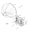
- FIG. 1 shows a towing mirror 40, which comprises a mirror assembly 36, an arm 12 connected to the mirror assembly 36, and a pair of clamps 10.
- the towing mirror 40 is shown as being provided with two clamps 10, but could be fitted with a single clamp 10 and would still be usable, although two clamps 10 clearly provide a more stable connection.
- the towing mirror 40 is designed to be fitted to a vehicle wing mirror, using the clamps 10.
- Each clamp 10 is provided with a moveable clamping member 26, which can be raised and lowered in order to clamp each individual clamp 10 onto the wing mirror.
- Each moveable clamping member 26 comprises a shaft 28 and an engaging portion 30.
- the clamp 10 is comprised of three principal components, of which the moveable clamping member 26 is one.
- the other two main components are a frame 14 and a gripping element 20 (see Figure 2 ).
- the frame 14 comprises an upright portion 16 and a lip 18 located at a lower end of the upright portion 16 and extending substantially perpendicularly to the upright portion 16.
- the gripping element 20 is connected to the frame 14 and is arranged to mount on the arm 12, and comprises a first component 22 and a second component 24 (also shown in more detail in Figure 2 ) that are connected together at one end and spaced apart at the other end, the arm 12 being located between the first component 22 and the second component 24.
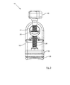
- Figures 2 and 3 show the clamp 10 in more detail.
- Figure 2 is a side view of the clamp 10 and
- Figure 3 is a front view of the clamp 10.
- the clamp 10 is for mounting on the arm 12.
- the clamp 10 comprises a frame 14, a gripping element 20 connected to the frame 14 and a moveable clamping member 26 which is mounted through a hole in the gripping element 20.
- the frame 14 comprises an upright portion 16 and a lip 18 located at a lower end of the upright portion 16 and extending substantially perpendicularly to the upright portion 16.
- the lip 18 is curved on its underside, in order to make it easier for the clamp 10 to be fixed into position on a curved vehicle wing mirror.
- the gripping element 20 is connected to the frame 14 and is arranged to mount on the arm 12, and comprises a first component 22 and a second component 24 connected together at one end and spaced apart at the other end, the arm 12 to be located between the first component 22 and the second component 24.
- the first component 22 and the second component 24 are shaped to define a hole 34, through which the arm 12 is to be located.
- the moveable clamping member 26 is mounted through a hole in the second component 24, and comprises a shaft 28 and an engaging portion 30 arranged to be moved towards the lip 18 of the frame 14.
- the engaging portion 30 of the moveable clamping member 26 is loosely mounted on the shaft 28 and can rotate relative to the shaft 28.
- Figures 4 and 5 show the towing mirror 40 fixed in position on a curved vehicle wing mirror 38.
- Figure 4 shows a perspective view from above of the towing mirror fixed onto the wing mirror 38 using two clamps 10 and
- Figure 5 shows a cross-section through the wing mirror 38 at a point close to the fixing of one of the clamps 10.
- Each clamp 10 is located on the wing mirror 38 such that the lip 18 of the frame 14 passes between the mirror 42 and edge 44 of the wing mirror 38.
- the knob 46 to rotate the shaft 28.
- the shaft 28 has a screw thread thereon, and the engaging portion 30 can be raised or lowered by rotation of the shaft 28.
- the principal advantage of the clamp 10 is that only a single fixing element is needed to fix the clamp 10 both to the wing mirror 38 and to the arm 12.
- the knob 46 As the user turns the knob 46 to lower the engaging portion 30 of the moveable clamping member 26, relative movement occurs between the shaft 28 and the second component 24 (which mounts the shaft 28). At first, this relative movement will cause the engaging portion 30 to be lowered to engage the outer part of the wing mirror 38.
- the relative movement between the shaft 28 and the second component 24 will force the second component 24 upwards, clamping the arm 12. Therefore the user's single action of turning the knob 46 will firstly clamp the clamp 10 to the wing mirror 38 and secondly clamp the clamp 10 to the arm 12.
- the engaging portion 30 In the view of Figure 5 the engaging portion 30 is in contact with the wing mirror 38, and at this point if the user were to continue to turn the knob 46 in a clockwise direction then the second component 24 would be moved upwards by this rotation, tightening onto the arm 12.
- Figure 6 shows a perspective view of a component of the clamp 10, being the frame 14.
- the upright portion 16 of the frame 14 is provided with a hole 32 through which the gripping element 20, shown in Figure 7 , is located.
- the gripping element 20 can rotate in the hole 32 relative to the upright portion 16 of the frame 14. This rotation allows the clamp 10 to be rotated to match the curvature of the wing mirror 38, as can be seen in Figure 4 , for example.
- the lip 18 of the frame 14 is also curved on the underside in order to allow the lip 18 to slide in-between the mirror 42 and the edge 44 of wing mirror 38.
- the gripping element 20 can be seen clearly in Figure 7 .
- the gripping element 20 comprises the first component 22 and the second component 24 connected together at one end and spaced apart at the other end, the arm 12 to be located between the first component 22 and the second component 24.
- the first component 22 and the second component 24 are shaped to define a hole 34, through which the arm 12 is to be located, where the cross-section of the hole 34 substantially matches the cross-section of the arm 12.
- the second component 24 of the gripping element 20 is longer than the first component 22 of the gripping element 20 and the shaft 28 of the moveable clamping member 26 does not pass through the first component 22 of the gripping element 20.
Landscapes
- Engineering & Computer Science (AREA)
- General Engineering & Computer Science (AREA)
- Mechanical Engineering (AREA)
- Multimedia (AREA)
- Physics & Mathematics (AREA)
- General Physics & Mathematics (AREA)
- Optics & Photonics (AREA)
- Rear-View Mirror Devices That Are Mounted On The Exterior Of The Vehicle (AREA)
Abstract
Description
- This invention relates to a clamp. The invention also relates to apparatus including a mirror assembly and the clamp. Such apparatus can be used by vehicle drivers, for example when the driver is towing a wide load and needs an extension to their conventional wing mirror.
- If a vehicle driver is towing a wide load, such as a car with a caravan, then it is advantageous, and in some jurisdictions a legal requirement, that the conventional vehicle wing mirror be extended, in order for the vehicle driver to be able to see behind and along the side of the wide load. To achieve this, it is known to provide apparatus, sometimes referred to as a towing mirror, which includes a mirror and a device for fixing that mirror to the conventional wing mirror. However, as vehicle design becomes more complicated and elaborate, there is a difficulty in providing a towing mirror that will fit all, or at least the vast majority, of wing mirror designs.
- United Kingdom Patent
GB 2444919 - It is therefore an object of the invention to improve upon the known art.
- According to the present invention, there is provided a clamp for mounting on an arm, the clamp comprising a frame comprising an upright portion and a lip located at a lower end of the upright portion and extending substantially perpendicularly to the upright portion, a gripping element connected to the frame and arranged to mount on the arm, and comprising a first component and a second component connected together at one end and spaced apart at the other end, the arm to be located between the first component and the second component, and a moveable clamping member, mounted through a hole in the second component, and comprising a shaft and an engaging portion arranged to be moved towards the lip of the frame.
- Owing to the invention, it is possible to provide a clamp that can be used in a towing mirror system that has only a single adjustable element, which makes the clamp much easier for a user to fix into position and also simplifies the manufacturing process for the clamp. The moveable clamping member, which is essentially to fix the clamp to the vehicle wing mirror, also performs the function of fixing the clamp to the arm of the towing mirror (which in the prior art towing mirror required a second element to perform this fixing). As the moveable clamping member is tightened onto the vehicle wing mirror, the two halves of the gripping element (the first and second components) are forced together, thereby gripping onto the arm of the towing mirror.
- Preferably, the upright portion of the frame is provided with a hole through which the gripping element is located and the gripping element can rotate in the hole relative to the upright portion of the frame. In a preferred embodiment of the invention, the upright portion of the frame of the clamp is provided with a hole through which the gripping element is located. The gripping element can rotate in this hole and this increases the flexibility of the clamps when they are fitted since the frame of the clamp can be rotated at an angle to the moveable clamping member. When the clamp is fitted to a vehicle wing mirror, this allows the rotation to be used to compensate for any curvature in the external surface of the wing mirror, as is common on modern vehicle wing mirrors.
- Embodiments of the present invention will now be described, by way of example only, with reference to the accompanying drawings, in which:-
-
Figure 1 is a perspective view of a towing mirror, -
Figure 2 is a side view of a clamp, -
Figure 3 is a front view of the clamp, -
Figure 4 is a perspective view of the towing mirror fixed to a wing mirror, -
Figure 5 is a section through the wing mirror ofFigure 4 , -
Figure 6 is a perspective view of a frame of the clamp, and -
Figure 7 is a perspective view of a gripping element of the clamp. -
Figure 1 shows atowing mirror 40, which comprises amirror assembly 36, anarm 12 connected to themirror assembly 36, and a pair ofclamps 10. Thetowing mirror 40 is shown as being provided with twoclamps 10, but could be fitted with asingle clamp 10 and would still be usable, although twoclamps 10 clearly provide a more stable connection. Thetowing mirror 40 is designed to be fitted to a vehicle wing mirror, using theclamps 10. Eachclamp 10 is provided with amoveable clamping member 26, which can be raised and lowered in order to clamp eachindividual clamp 10 onto the wing mirror. Eachmoveable clamping member 26 comprises ashaft 28 and anengaging portion 30. - The
clamp 10 is comprised of three principal components, of which themoveable clamping member 26 is one. The other two main components are aframe 14 and a gripping element 20 (seeFigure 2 ). Theframe 14 comprises anupright portion 16 and alip 18 located at a lower end of theupright portion 16 and extending substantially perpendicularly to theupright portion 16. Thegripping element 20 is connected to theframe 14 and is arranged to mount on thearm 12, and comprises afirst component 22 and a second component 24 (also shown in more detail inFigure 2 ) that are connected together at one end and spaced apart at the other end, thearm 12 being located between thefirst component 22 and thesecond component 24. -
Figures 2 and3 show theclamp 10 in more detail.Figure 2 is a side view of theclamp 10 andFigure 3 is a front view of theclamp 10. Theclamp 10 is for mounting on thearm 12. Theclamp 10 comprises aframe 14, agripping element 20 connected to theframe 14 and amoveable clamping member 26 which is mounted through a hole in thegripping element 20. Theframe 14 comprises anupright portion 16 and alip 18 located at a lower end of theupright portion 16 and extending substantially perpendicularly to theupright portion 16. Thelip 18 is curved on its underside, in order to make it easier for theclamp 10 to be fixed into position on a curved vehicle wing mirror. - The
gripping element 20 is connected to theframe 14 and is arranged to mount on thearm 12, and comprises afirst component 22 and asecond component 24 connected together at one end and spaced apart at the other end, thearm 12 to be located between thefirst component 22 and thesecond component 24. Thefirst component 22 and thesecond component 24 are shaped to define ahole 34, through which thearm 12 is to be located. Themoveable clamping member 26 is mounted through a hole in thesecond component 24, and comprises ashaft 28 and anengaging portion 30 arranged to be moved towards thelip 18 of theframe 14. Theengaging portion 30 of themoveable clamping member 26 is loosely mounted on theshaft 28 and can rotate relative to theshaft 28. -
Figures 4 and5 show thetowing mirror 40 fixed in position on a curvedvehicle wing mirror 38.Figure 4 shows a perspective view from above of the towing mirror fixed onto thewing mirror 38 using twoclamps 10 andFigure 5 shows a cross-section through thewing mirror 38 at a point close to the fixing of one of theclamps 10. Eachclamp 10 is located on thewing mirror 38 such that thelip 18 of theframe 14 passes between themirror 42 andedge 44 of thewing mirror 38. Once eachclamp 10 has been located into position by the user, then the user will turn theknob 46 to rotate theshaft 28. Theshaft 28 has a screw thread thereon, and theengaging portion 30 can be raised or lowered by rotation of theshaft 28. - The principal advantage of the
clamp 10 is that only a single fixing element is needed to fix theclamp 10 both to thewing mirror 38 and to thearm 12. As the user turns theknob 46 to lower theengaging portion 30 of themoveable clamping member 26, relative movement occurs between theshaft 28 and the second component 24 (which mounts the shaft 28). At first, this relative movement will cause theengaging portion 30 to be lowered to engage the outer part of thewing mirror 38. However, once theengaging portion 30 has reached the full extent of its movement, as the user continues to turn theknob 46, the relative movement between theshaft 28 and thesecond component 24 will force thesecond component 24 upwards, clamping thearm 12. Therefore the user's single action of turning theknob 46 will firstly clamp theclamp 10 to thewing mirror 38 and secondly clamp theclamp 10 to thearm 12. In the view ofFigure 5 theengaging portion 30 is in contact with thewing mirror 38, and at this point if the user were to continue to turn theknob 46 in a clockwise direction then thesecond component 24 would be moved upwards by this rotation, tightening onto thearm 12. -
Figure 6 shows a perspective view of a component of theclamp 10, being theframe 14. Theupright portion 16 of theframe 14 is provided with ahole 32 through which thegripping element 20, shown inFigure 7 , is located. Thegripping element 20 can rotate in thehole 32 relative to theupright portion 16 of theframe 14. This rotation allows theclamp 10 to be rotated to match the curvature of thewing mirror 38, as can be seen inFigure 4 , for example. Thelip 18 of theframe 14 is also curved on the underside in order to allow thelip 18 to slide in-between themirror 42 and theedge 44 ofwing mirror 38. - The
gripping element 20 can be seen clearly inFigure 7 . Thegripping element 20 comprises thefirst component 22 and thesecond component 24 connected together at one end and spaced apart at the other end, thearm 12 to be located between thefirst component 22 and thesecond component 24. Thefirst component 22 and thesecond component 24 are shaped to define ahole 34, through which thearm 12 is to be located, where the cross-section of thehole 34 substantially matches the cross-section of thearm 12. Thesecond component 24 of thegripping element 20 is longer than thefirst component 22 of thegripping element 20 and theshaft 28 of themoveable clamping member 26 does not pass through thefirst component 22 of thegripping element 20.
Claims (10)
- A clamp (10) for mounting on an arm (12), the clamp (10) comprising:• a frame (14) comprising an upright portion (16) and a lip (18) located at a lower end of the upright portion (16) and extending substantially perpendicularly to the upright portion (16),• a gripping element (20) connected to the frame (14) and arranged to mount on the arm (12), and comprising a first component (22) and a second component (24) connected together at one end and spaced apart at the other end, the arm (12) to be located between the first component (22) and the second component (24), and• a moveable clamping member (26), mounted through a hole in the second component (24), and comprising a shaft (28) and an engaging portion (30) arranged to be moved towards the lip (18) of the frame (14).
- A clamp according to claim 1, wherein the shaft (28) of the moveable clamping member (26) has a screw thread thereon, and the engaging portion (30) can be raised or lowered by rotation of the shaft (28).
- A clamp according to claim 1 or 2, wherein the upright portion (16) of the frame (14) is provided with a hole (32) through which the gripping element (20) is located.
- A clamp according to claim 3, wherein the gripping element (20) can rotate in the hole (32) relative to the upright portion (16) of the frame (14).
- A clamp according to any preceding claim, wherein the first component (22) and the second component (24) are shaped to define a hole (34), through which the arm (12) is to be located.
- A clamp according to claim 5, wherein the cross-section of the hole (34) substantially matches the cross-section of the arm (12).
- A clamp according to any preceding claim, wherein the second component (24) of the gripping element (20) is longer than the first component (22) of the gripping element (20) and the shaft (28) of the moveable clamping member (26) does not pass through the first component (22) of the gripping element (20).
- A clamp according to any preceding claim, wherein the engaging portion (30) of the moveable clamping member (26) is loosely mounted on the shaft (28) and can rotate relative to the shaft (28).
- Apparatus comprising a mirror assembly (36), an arm (12) connected to the mirror assembly (36), and a clamp (10), according to any one of claims 1 to 8, mounted on the arm (12).
- Apparatus according to claim 9, and further comprising a second clamp (10), according to any one of claims 1 to 8, mounted on the arm (12).
Applications Claiming Priority (1)
| Application Number | Priority Date | Filing Date | Title |
|---|---|---|---|
| GB1317833.0A GB2519096B (en) | 2013-10-09 | 2013-10-09 | A clamp |
Publications (2)
| Publication Number | Publication Date |
|---|---|
| EP2860064A1 true EP2860064A1 (en) | 2015-04-15 |
| EP2860064B1 EP2860064B1 (en) | 2016-08-31 |
Family
ID=49630399
Family Applications (1)
| Application Number | Title | Priority Date | Filing Date |
|---|---|---|---|
| EP14184796.2A Active EP2860064B1 (en) | 2013-10-09 | 2014-09-15 | A clamp |
Country Status (5)
| Country | Link |
|---|---|
| US (1) | US9327647B2 (en) |
| EP (1) | EP2860064B1 (en) |
| AU (1) | AU2014233603B2 (en) |
| DK (1) | DK2860064T3 (en) |
| GB (1) | GB2519096B (en) |
Families Citing this family (5)
| Publication number | Priority date | Publication date | Assignee | Title |
|---|---|---|---|---|
| US20180001824A1 (en) | 2016-07-01 | 2018-01-04 | Protomet Corporation | Adjustable Mirror Bracket |
| US10674842B1 (en) * | 2019-09-30 | 2020-06-09 | Protomet Corporation | Hinged deployable mirror bracket |
| US11821576B1 (en) | 2019-12-11 | 2023-11-21 | Protomet Corporation | Center console mirror bracket |
| GB2598620B (en) * | 2020-09-07 | 2022-12-14 | Milenco Ltd | Enhanced flexible gripper pad for towing mirror clamp |
| CN112498544A (en) * | 2020-12-01 | 2021-03-16 | 徐州台铃车业有限公司 | Rearview mirror mounting assembly for electric tricycle |
Citations (5)
| Publication number | Priority date | Publication date | Assignee | Title |
|---|---|---|---|---|
| EP0437695A1 (en) * | 1990-01-16 | 1991-07-24 | HAGUS C. LUCHTENBERG GmbH & Co. KG | Auxiliary external mirror for motor vehicles |
| JP2002374109A (en) * | 2001-06-15 | 2002-12-26 | Maspro Denkoh Corp | Antenna mounting |
| DE102005062046B3 (en) * | 2005-12-22 | 2007-08-02 | Emuk Elektro-Maschinen- Und Kunststoffteile-Vertriebsgesellschaft Mbh | Removable additional external mirror for motor vehicle has vice-like clamp part that has at least one clamping element and that is connected to additional external mirror housing |
| EP1935718A2 (en) * | 2006-12-20 | 2008-06-25 | Milenco Limited | Apparatus including a mirror assembly |
| DE202012104560U1 (en) * | 2012-11-26 | 2012-12-06 | Fang-Mei Kuo | Auxiliary structure for rearview mirror |
Family Cites Families (11)
| Publication number | Priority date | Publication date | Assignee | Title |
|---|---|---|---|---|
| US5259582A (en) * | 1992-06-22 | 1993-11-09 | Delange Iii William | Extension mounting arms and attachment devices for rear view mirrors for personal recreational vehicles |
| US6217180B1 (en) * | 1998-10-20 | 2001-04-17 | United Global Sourcing, Inc. | Rearview mirror for baby stroller |
| US6910781B2 (en) * | 2002-06-26 | 2005-06-28 | Velvac, Inc. | Quick release vehicle mirror |
| US6679612B1 (en) * | 2002-06-28 | 2004-01-20 | Robin J. West | Adjustable mirror and sound system for a rear seat of a vehicle |
| US20080259477A1 (en) * | 2007-04-18 | 2008-10-23 | Janice Gorton | Rear vision activity mirror |
| AU2008295436B2 (en) * | 2007-09-03 | 2012-12-13 | Michael Ferman | Rear view mirror |
| DE202010009347U1 (en) * | 2010-01-20 | 2011-06-01 | MEKRA Lang GmbH & Co. KG, 90765 | Adapter for precise fitting and position fixing of a mirror unit |
| US8820548B2 (en) * | 2011-02-23 | 2014-09-02 | Bambinos!, Llc | Tray device |
| US8636370B2 (en) * | 2011-08-26 | 2014-01-28 | T.Y.C. Brother Industries Co., Ltd. | Engagement assembly for connecting reflector and connecting rod |
| DK201100146U4 (en) * | 2011-09-30 | 2013-01-25 | Brunsgaard Aps | Towing mirror-holder |
| US20140085739A1 (en) * | 2012-09-26 | 2014-03-27 | Protomet Corporation | Pontoon Mirror Bracket System |
-
2013
- 2013-10-09 GB GB1317833.0A patent/GB2519096B/en active Active
-
2014
- 2014-09-15 DK DK14184796.2T patent/DK2860064T3/en active
- 2014-09-15 EP EP14184796.2A patent/EP2860064B1/en active Active
- 2014-09-25 AU AU2014233603A patent/AU2014233603B2/en active Active
- 2014-09-25 US US14/497,000 patent/US9327647B2/en active Active
Patent Citations (5)
| Publication number | Priority date | Publication date | Assignee | Title |
|---|---|---|---|---|
| EP0437695A1 (en) * | 1990-01-16 | 1991-07-24 | HAGUS C. LUCHTENBERG GmbH & Co. KG | Auxiliary external mirror for motor vehicles |
| JP2002374109A (en) * | 2001-06-15 | 2002-12-26 | Maspro Denkoh Corp | Antenna mounting |
| DE102005062046B3 (en) * | 2005-12-22 | 2007-08-02 | Emuk Elektro-Maschinen- Und Kunststoffteile-Vertriebsgesellschaft Mbh | Removable additional external mirror for motor vehicle has vice-like clamp part that has at least one clamping element and that is connected to additional external mirror housing |
| EP1935718A2 (en) * | 2006-12-20 | 2008-06-25 | Milenco Limited | Apparatus including a mirror assembly |
| DE202012104560U1 (en) * | 2012-11-26 | 2012-12-06 | Fang-Mei Kuo | Auxiliary structure for rearview mirror |
Also Published As
| Publication number | Publication date |
|---|---|
| GB201317833D0 (en) | 2013-11-20 |
| US20150098145A1 (en) | 2015-04-09 |
| GB2519096A (en) | 2015-04-15 |
| AU2014233603A1 (en) | 2015-04-23 |
| EP2860064B1 (en) | 2016-08-31 |
| US9327647B2 (en) | 2016-05-03 |
| GB2519096B (en) | 2016-03-09 |
| DK2860064T3 (en) | 2016-12-19 |
| AU2014233603B2 (en) | 2017-11-23 |
Similar Documents
| Publication | Publication Date | Title |
|---|---|---|
| EP1935718B1 (en) | Apparatus including a mirror assembly | |
| EP2860064B1 (en) | A clamp | |
| US4718756A (en) | Multisegmented rear view mirror | |
| US1430379A (en) | Combination mirror and light shield | |
| DE102011116782B4 (en) | Interior rearview mirror assembly for a windshield | |
| US20160096485A1 (en) | Clamping apparatus with auxiliary mirror | |
| EP3760826A3 (en) | A screening device, a roof window comprising such a screening device and a method for mounting such a screening device on a roof window | |
| EP2826672A1 (en) | Mirror assembly with adjustable fastening | |
| JP2013090054A (en) | Fitting device | |
| GB2488775A (en) | Towing mirror clamp assembly | |
| US1522476A (en) | Windshield wing | |
| US8794580B1 (en) | Adjustable mounting bracket | |
| GB2481626A (en) | Gripper pad for vehicle towing mirror | |
| US6820516B2 (en) | Adjusting device for wheel brake cables of a manually-operated parking brake | |
| CN105946959B (en) | Steering device | |
| GB2529687A (en) | Improved gripper pad for towing mirror clamp | |
| CN112758169A (en) | Steering wheel integrated with display function | |
| EP3964397A1 (en) | Enhanced flexible gripper pad for towing mirror clamp | |
| US10864874B2 (en) | Restraint system for a driver of a vehicle | |
| US1628200A (en) | Windshield-wing mounting | |
| EP3256349B1 (en) | Mounting arrangement | |
| CN203995956U (en) | Clamping device with auxiliary mirror | |
| DE102010050184A1 (en) | Driver assistance camera for motor vehicle, has optical carrier with camera lens, and camera housing, where optical carrier is arranged in position adjustable manner in or at camera housing | |
| EP4523969A1 (en) | System for moving a device displaying contents of a road vehicle | |
| GB2579055A (en) | An assembly for supporting a rear view mirror |
Legal Events
| Date | Code | Title | Description |
|---|---|---|---|
| PUAI | Public reference made under article 153(3) epc to a published international application that has entered the european phase |
Free format text: ORIGINAL CODE: 0009012 |
|
| 17P | Request for examination filed |
Effective date: 20140915 |
|
| AK | Designated contracting states |
Kind code of ref document: A1 Designated state(s): AL AT BE BG CH CY CZ DE DK EE ES FI FR GB GR HR HU IE IS IT LI LT LU LV MC MK MT NL NO PL PT RO RS SE SI SK SM TR |
|
| AX | Request for extension of the european patent |
Extension state: BA ME |
|
| R17P | Request for examination filed (corrected) |
Effective date: 20151014 |
|
| RBV | Designated contracting states (corrected) |
Designated state(s): AL AT BE BG CH CY CZ DE DK EE ES FI FR GB GR HR HU IE IS IT LI LT LU LV MC MK MT NL NO PL PT RO RS SE SI SK SM TR |
|
| GRAP | Despatch of communication of intention to grant a patent |
Free format text: ORIGINAL CODE: EPIDOSNIGR1 |
|
| RIC1 | Information provided on ipc code assigned before grant |
Ipc: F16B 2/06 20060101ALI20160218BHEP Ipc: B60R 1/078 20060101AFI20160218BHEP Ipc: F16B 2/12 20060101ALI20160218BHEP |
|
| INTG | Intention to grant announced |
Effective date: 20160317 |
|
| GRAS | Grant fee paid |
Free format text: ORIGINAL CODE: EPIDOSNIGR3 |
|
| GRAA | (expected) grant |
Free format text: ORIGINAL CODE: 0009210 |
|
| RBV | Designated contracting states (corrected) |
Designated state(s): AL AT BE BG CH CY CZ DE DK EE ES FI FR GR HR HU IE IS IT LI LT LU LV MC MK MT NL NO PL PT RO RS SE SI SK SM TR |
|
| AK | Designated contracting states |
Kind code of ref document: B1 Designated state(s): AL AT BE BG CH CY CZ DE DK EE ES FI FR GR HR HU IE IS IT LI LT LU LV MC MK MT NL NO PL PT RO RS SE SI SK SM TR |
|
| REG | Reference to a national code |
Ref country code: CH Ref legal event code: EP |
|
| REG | Reference to a national code |
Ref country code: IE Ref legal event code: FG4D |
|
| REG | Reference to a national code |
Ref country code: DE Ref legal event code: R096 Ref document number: 602014003363 Country of ref document: DE |
|
| REG | Reference to a national code |
Ref country code: AT Ref legal event code: REF Ref document number: 824672 Country of ref document: AT Kind code of ref document: T Effective date: 20161015 |
|
| REG | Reference to a national code |
Ref country code: FR Ref legal event code: PLFP Year of fee payment: 3 |
|
| REG | Reference to a national code |
Ref country code: NL Ref legal event code: FP |
|
| REG | Reference to a national code |
Ref country code: SE Ref legal event code: TRGR |
|
| REG | Reference to a national code |
Ref country code: DK Ref legal event code: T3 Effective date: 20161218 |
|
| REG | Reference to a national code |
Ref country code: LT Ref legal event code: MG4D |
|
| REG | Reference to a national code |
Ref country code: AT Ref legal event code: MK05 Ref document number: 824672 Country of ref document: AT Kind code of ref document: T Effective date: 20160831 |
|
| PG25 | Lapsed in a contracting state [announced via postgrant information from national office to epo] |
Ref country code: FI Free format text: LAPSE BECAUSE OF FAILURE TO SUBMIT A TRANSLATION OF THE DESCRIPTION OR TO PAY THE FEE WITHIN THE PRESCRIBED TIME-LIMIT Effective date: 20160831 Ref country code: HR Free format text: LAPSE BECAUSE OF FAILURE TO SUBMIT A TRANSLATION OF THE DESCRIPTION OR TO PAY THE FEE WITHIN THE PRESCRIBED TIME-LIMIT Effective date: 20160831 Ref country code: LT Free format text: LAPSE BECAUSE OF FAILURE TO SUBMIT A TRANSLATION OF THE DESCRIPTION OR TO PAY THE FEE WITHIN THE PRESCRIBED TIME-LIMIT Effective date: 20160831 Ref country code: RS Free format text: LAPSE BECAUSE OF FAILURE TO SUBMIT A TRANSLATION OF THE DESCRIPTION OR TO PAY THE FEE WITHIN THE PRESCRIBED TIME-LIMIT Effective date: 20160831 Ref country code: NO Free format text: LAPSE BECAUSE OF FAILURE TO SUBMIT A TRANSLATION OF THE DESCRIPTION OR TO PAY THE FEE WITHIN THE PRESCRIBED TIME-LIMIT Effective date: 20161130 |
|
| PG25 | Lapsed in a contracting state [announced via postgrant information from national office to epo] |
Ref country code: BE Free format text: LAPSE BECAUSE OF NON-PAYMENT OF DUE FEES Effective date: 20160930 Ref country code: LV Free format text: LAPSE BECAUSE OF FAILURE TO SUBMIT A TRANSLATION OF THE DESCRIPTION OR TO PAY THE FEE WITHIN THE PRESCRIBED TIME-LIMIT Effective date: 20160831 Ref country code: AT Free format text: LAPSE BECAUSE OF FAILURE TO SUBMIT A TRANSLATION OF THE DESCRIPTION OR TO PAY THE FEE WITHIN THE PRESCRIBED TIME-LIMIT Effective date: 20160831 Ref country code: GR Free format text: LAPSE BECAUSE OF FAILURE TO SUBMIT A TRANSLATION OF THE DESCRIPTION OR TO PAY THE FEE WITHIN THE PRESCRIBED TIME-LIMIT Effective date: 20161201 Ref country code: ES Free format text: LAPSE BECAUSE OF FAILURE TO SUBMIT A TRANSLATION OF THE DESCRIPTION OR TO PAY THE FEE WITHIN THE PRESCRIBED TIME-LIMIT Effective date: 20160831 |
|
| PG25 | Lapsed in a contracting state [announced via postgrant information from national office to epo] |
Ref country code: RO Free format text: LAPSE BECAUSE OF FAILURE TO SUBMIT A TRANSLATION OF THE DESCRIPTION OR TO PAY THE FEE WITHIN THE PRESCRIBED TIME-LIMIT Effective date: 20160831 Ref country code: EE Free format text: LAPSE BECAUSE OF FAILURE TO SUBMIT A TRANSLATION OF THE DESCRIPTION OR TO PAY THE FEE WITHIN THE PRESCRIBED TIME-LIMIT Effective date: 20160831 |
|
| PG25 | Lapsed in a contracting state [announced via postgrant information from national office to epo] |
Ref country code: PT Free format text: LAPSE BECAUSE OF FAILURE TO SUBMIT A TRANSLATION OF THE DESCRIPTION OR TO PAY THE FEE WITHIN THE PRESCRIBED TIME-LIMIT Effective date: 20170102 Ref country code: BE Free format text: LAPSE BECAUSE OF FAILURE TO SUBMIT A TRANSLATION OF THE DESCRIPTION OR TO PAY THE FEE WITHIN THE PRESCRIBED TIME-LIMIT Effective date: 20160831 Ref country code: SK Free format text: LAPSE BECAUSE OF FAILURE TO SUBMIT A TRANSLATION OF THE DESCRIPTION OR TO PAY THE FEE WITHIN THE PRESCRIBED TIME-LIMIT Effective date: 20160831 Ref country code: SM Free format text: LAPSE BECAUSE OF FAILURE TO SUBMIT A TRANSLATION OF THE DESCRIPTION OR TO PAY THE FEE WITHIN THE PRESCRIBED TIME-LIMIT Effective date: 20160831 Ref country code: BG Free format text: LAPSE BECAUSE OF FAILURE TO SUBMIT A TRANSLATION OF THE DESCRIPTION OR TO PAY THE FEE WITHIN THE PRESCRIBED TIME-LIMIT Effective date: 20161130 Ref country code: CZ Free format text: LAPSE BECAUSE OF FAILURE TO SUBMIT A TRANSLATION OF THE DESCRIPTION OR TO PAY THE FEE WITHIN THE PRESCRIBED TIME-LIMIT Effective date: 20160831 Ref country code: PL Free format text: LAPSE BECAUSE OF FAILURE TO SUBMIT A TRANSLATION OF THE DESCRIPTION OR TO PAY THE FEE WITHIN THE PRESCRIBED TIME-LIMIT Effective date: 20160831 |
|
| REG | Reference to a national code |
Ref country code: DE Ref legal event code: R097 Ref document number: 602014003363 Country of ref document: DE |
|
| REG | Reference to a national code |
Ref country code: IE Ref legal event code: MM4A |
|
| PG25 | Lapsed in a contracting state [announced via postgrant information from national office to epo] |
Ref country code: IT Free format text: LAPSE BECAUSE OF FAILURE TO SUBMIT A TRANSLATION OF THE DESCRIPTION OR TO PAY THE FEE WITHIN THE PRESCRIBED TIME-LIMIT Effective date: 20160831 |
|
| PLBE | No opposition filed within time limit |
Free format text: ORIGINAL CODE: 0009261 |
|
| STAA | Information on the status of an ep patent application or granted ep patent |
Free format text: STATUS: NO OPPOSITION FILED WITHIN TIME LIMIT |
|
| PG25 | Lapsed in a contracting state [announced via postgrant information from national office to epo] |
Ref country code: IE Free format text: LAPSE BECAUSE OF NON-PAYMENT OF DUE FEES Effective date: 20160915 |
|
| 26N | No opposition filed |
Effective date: 20170601 |
|
| REG | Reference to a national code |
Ref country code: FR Ref legal event code: PLFP Year of fee payment: 4 |
|
| PG25 | Lapsed in a contracting state [announced via postgrant information from national office to epo] |
Ref country code: LU Free format text: LAPSE BECAUSE OF NON-PAYMENT OF DUE FEES Effective date: 20160915 Ref country code: SI Free format text: LAPSE BECAUSE OF FAILURE TO SUBMIT A TRANSLATION OF THE DESCRIPTION OR TO PAY THE FEE WITHIN THE PRESCRIBED TIME-LIMIT Effective date: 20160831 |
|
| REG | Reference to a national code |
Ref country code: CH Ref legal event code: PL |
|
| PG25 | Lapsed in a contracting state [announced via postgrant information from national office to epo] |
Ref country code: HU Free format text: LAPSE BECAUSE OF FAILURE TO SUBMIT A TRANSLATION OF THE DESCRIPTION OR TO PAY THE FEE WITHIN THE PRESCRIBED TIME-LIMIT; INVALID AB INITIO Effective date: 20140915 |
|
| PG25 | Lapsed in a contracting state [announced via postgrant information from national office to epo] |
Ref country code: MC Free format text: LAPSE BECAUSE OF FAILURE TO SUBMIT A TRANSLATION OF THE DESCRIPTION OR TO PAY THE FEE WITHIN THE PRESCRIBED TIME-LIMIT Effective date: 20160831 Ref country code: MT Free format text: LAPSE BECAUSE OF NON-PAYMENT OF DUE FEES Effective date: 20160930 Ref country code: CY Free format text: LAPSE BECAUSE OF FAILURE TO SUBMIT A TRANSLATION OF THE DESCRIPTION OR TO PAY THE FEE WITHIN THE PRESCRIBED TIME-LIMIT Effective date: 20160831 Ref country code: MK Free format text: LAPSE BECAUSE OF FAILURE TO SUBMIT A TRANSLATION OF THE DESCRIPTION OR TO PAY THE FEE WITHIN THE PRESCRIBED TIME-LIMIT Effective date: 20160831 Ref country code: IS Free format text: LAPSE BECAUSE OF FAILURE TO SUBMIT A TRANSLATION OF THE DESCRIPTION OR TO PAY THE FEE WITHIN THE PRESCRIBED TIME-LIMIT Effective date: 20160831 |
|
| PG25 | Lapsed in a contracting state [announced via postgrant information from national office to epo] |
Ref country code: CH Free format text: LAPSE BECAUSE OF NON-PAYMENT OF DUE FEES Effective date: 20170930 Ref country code: LI Free format text: LAPSE BECAUSE OF NON-PAYMENT OF DUE FEES Effective date: 20170930 |
|
| REG | Reference to a national code |
Ref country code: FR Ref legal event code: PLFP Year of fee payment: 5 |
|
| PG25 | Lapsed in a contracting state [announced via postgrant information from national office to epo] |
Ref country code: TR Free format text: LAPSE BECAUSE OF FAILURE TO SUBMIT A TRANSLATION OF THE DESCRIPTION OR TO PAY THE FEE WITHIN THE PRESCRIBED TIME-LIMIT Effective date: 20160831 Ref country code: AL Free format text: LAPSE BECAUSE OF FAILURE TO SUBMIT A TRANSLATION OF THE DESCRIPTION OR TO PAY THE FEE WITHIN THE PRESCRIBED TIME-LIMIT Effective date: 20160831 |
|
| PGFP | Annual fee paid to national office [announced via postgrant information from national office to epo] |
Ref country code: DK Payment date: 20250915 Year of fee payment: 12 Ref country code: DE Payment date: 20250915 Year of fee payment: 12 |
|
| PGFP | Annual fee paid to national office [announced via postgrant information from national office to epo] |
Ref country code: NL Payment date: 20250923 Year of fee payment: 12 |
|
| PGFP | Annual fee paid to national office [announced via postgrant information from national office to epo] |
Ref country code: FR Payment date: 20250924 Year of fee payment: 12 |
|
| PGFP | Annual fee paid to national office [announced via postgrant information from national office to epo] |
Ref country code: SE Payment date: 20250916 Year of fee payment: 12 |