EP1935718A2 - Apparatus including a mirror assembly - Google Patents
Apparatus including a mirror assembly Download PDFInfo
- Publication number
- EP1935718A2 EP1935718A2 EP07024372A EP07024372A EP1935718A2 EP 1935718 A2 EP1935718 A2 EP 1935718A2 EP 07024372 A EP07024372 A EP 07024372A EP 07024372 A EP07024372 A EP 07024372A EP 1935718 A2 EP1935718 A2 EP 1935718A2
- Authority
- EP
- European Patent Office
- Prior art keywords
- clamp
- arm
- bracket
- mirror
- engaging portion
- Prior art date
- Legal status (The legal status is an assumption and is not a legal conclusion. Google has not performed a legal analysis and makes no representation as to the accuracy of the status listed.)
- Granted
Links
- 238000010276 construction Methods 0.000 description 1
Images


Classifications
-
- B—PERFORMING OPERATIONS; TRANSPORTING
- B60—VEHICLES IN GENERAL
- B60R—VEHICLES, VEHICLE FITTINGS, OR VEHICLE PARTS, NOT OTHERWISE PROVIDED FOR
- B60R1/00—Optical viewing arrangements; Real-time viewing arrangements for drivers or passengers using optical image capturing systems, e.g. cameras or video systems specially adapted for use in or on vehicles
- B60R1/02—Rear-view mirror arrangements
- B60R1/06—Rear-view mirror arrangements mounted on vehicle exterior
- B60R1/078—Rear-view mirror arrangements mounted on vehicle exterior easily removable; mounted for bodily outward movement, e.g. when towing
-
- B—PERFORMING OPERATIONS; TRANSPORTING
- B60—VEHICLES IN GENERAL
- B60R—VEHICLES, VEHICLE FITTINGS, OR VEHICLE PARTS, NOT OTHERWISE PROVIDED FOR
- B60R1/00—Optical viewing arrangements; Real-time viewing arrangements for drivers or passengers using optical image capturing systems, e.g. cameras or video systems specially adapted for use in or on vehicles
- B60R1/02—Rear-view mirror arrangements
- B60R1/08—Rear-view mirror arrangements involving special optical features, e.g. avoiding blind spots, e.g. convex mirrors; Side-by-side associations of rear-view and other mirrors
- B60R1/081—Rear-view mirror arrangements involving special optical features, e.g. avoiding blind spots, e.g. convex mirrors; Side-by-side associations of rear-view and other mirrors avoiding blind spots, e.g. by using a side-by-side association of mirrors
-
- F—MECHANICAL ENGINEERING; LIGHTING; HEATING; WEAPONS; BLASTING
- F16—ENGINEERING ELEMENTS AND UNITS; GENERAL MEASURES FOR PRODUCING AND MAINTAINING EFFECTIVE FUNCTIONING OF MACHINES OR INSTALLATIONS; THERMAL INSULATION IN GENERAL
- F16B—DEVICES FOR FASTENING OR SECURING CONSTRUCTIONAL ELEMENTS OR MACHINE PARTS TOGETHER, e.g. NAILS, BOLTS, CIRCLIPS, CLAMPS, CLIPS OR WEDGES; JOINTS OR JOINTING
- F16B2/00—Friction-grip releasable fastenings
- F16B2/02—Clamps, i.e. with gripping action effected by positive means other than the inherent resistance to deformation of the material of the fastening
- F16B2/06—Clamps, i.e. with gripping action effected by positive means other than the inherent resistance to deformation of the material of the fastening external, i.e. with contracting action
- F16B2/12—Clamps, i.e. with gripping action effected by positive means other than the inherent resistance to deformation of the material of the fastening external, i.e. with contracting action using sliding jaws
Definitions
- This invention relates to apparatus including a mirror assembly.
- Such apparatus can be used by vehicle drivers, for example when the driver is towing a wide load and needs an extension to their conventional wing mirror.
- a vehicle driver is towing a wide load, such as a car with a caravan
- a wide load such as a car with a caravan
- the conventional vehicle wing mirror be extended, in order for the vehicle driver to be able to see behind and along the side of the wide load.
- apparatus sometimes referred to as a towing mirror, which includes a mirror and a device for fixing that mirror to the conventional wing mirror.
- a towing mirror which includes a mirror and a device for fixing that mirror to the conventional wing mirror.
- apparatus comprising a mirror assembly, an arm connected to the mirror assembly, and a bracket mounted on the arm, the bracket comprising a clamp for connecting to a vehicle wing mirror, characterised in that the clamp is rotatable about an axis substantially perpendicular to the arm.
- the apparatus further comprises a second bracket mounted on the arm, the second bracket comprising a clamp for connecting to a vehicle wing mirror, wherein the clamp is rotatable about an axis substantially perpendicular to the arm.
- the provision of two brackets on the arm provides a towing mirror that can be very securely fastened to a vehicle wing mirror.
- the clamp comprises a frame and a movable clamping member, the clamping member including an engaging portion, the engaging portion is connected to a shaft and is turnably mounted on the shaft, and one of the frame and the engaging portion includes a guiding slot, and the other of the frame and the engaging portion includes a guiding element engaging in the guiding slot.
- apparatus comprising a clamp, the clamp comprising a frame and a movable clamping member, the clamping member including an engaging portion, characterised in that one of the frame and the engaging portion includes a guiding slot, and the other of the frame and the engaging portion includes a guiding element engaging in the guiding slot.
- FIG. 1 shows the apparatus 10, which comprising a mirror assembly 12, an arm 14 connected to the mirror assembly 12, and two brackets 16 mounted on the arm 14.
- Each bracket 16 comprises a clamp 18 for connecting to a vehicle wing mirror (not shown), and each clamp 18 is rotatable about an axis A, the axis A being substantially perpendicular to the arm 14.
- the apparatus 10 is shown with two brackets 16, as a preferred embodiment, but the apparatus 10 could equally well be provided with only a single bracket 16.
- Each bracket 16 also includes a fixing portion 20 for connecting the respective bracket 16 directly to the arm 14 of the apparatus 10, and a shaft 22 for connecting the clamp 18 to the fixing portion 20.
- the clamp 18 is rotatable about the shaft 22.
- Each bracket 16 also includes a locking element 24 for preventing rotation of the clamp 20.
- the shaft 22, with the locking element 24 fixably mounted thereto can be a screw-thread that the clamp 18 will rotate about.
- the locking element 24 can be unscrewed to allow the clamp 18 to be rotated into position, and then the locking element 24 can be retightened to fix the clamp 18 in position, so that the clamp 18 can no longer move relative to the arm 14.
- each bracket 16 Since the apparatus 10 is designed as a towing mirror, a wide variety of different shapes of vehicle wing mirror can have the apparatus 10 fixed thereto.
- the provision of the rotation of the clamp 18 on each bracket 16 allows each clamp 18 to be positioned to best suit the local shape of the vehicle wing mirror to which the bracket 16 is being fixed.
- a vehicle wing mirror with a varying shape can be connected to, without any impact on the performance of the towing mirror. Such a connection is relatively easy for a user to make themselves without any specialist assistance.
- the apparatus 10 is designed to fit to a wing mirror of a vehicle such as a car.
- the apparatus 10 allows the driver of the car to be able to see behind them, by extending the mirror assembly 12 out and beyond a wide load that the car may be towing.
- the arm 14 of the apparatus 10 extends in the same plane as the mirror assembly 12, out to the side of the mirror assembly 12, and is at least twice the length of the mirror assembly 12.
- the arm 14 is also, at least twice as long as the brackets 16 are wide, so that it can support at least two brackets 16.
- the arm 14 is an elongate rod-like construction, which mounts the brackets 16 so that they are alongside the mirror assembly 12.
- Each clamp 18 comprises a frame 26 and a movable clamping member 28, the clamping member 28 including an engaging portion (shown in Figure 2 ).
- the engaging portion is connected to a shaft 30 and is turnably mounted on the shaft 30.
- the frame includes a guiding slot 32, and the engaging portion includes a guiding element 34 engaging in the guiding slot 32.
- the purpose of the guiding element 34 and the slot 32 is to assist in the locating and moving of the engaging portion.
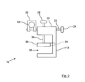
- FIG 2 shows this engaging portion 36, in a side view of the apparatus 10 of Figure 1 , with the mirror assembly 12 removed for clarity.
- the bracket 16 comprises the clamp 18, the fixing portion 20 and the shaft 22.
- the clamp 18 can turn about the shaft 22, and the locking element 24 is used to tighten the clamp 18 against the fixing portion 20, when the correct position has been chosen by a user.
- the user turns the shaft 30 via the knob of the clamping member 28 and this raises and lowers the engaging portion 36, which is loosely mounted on the shaft 30. This allows the engaging portion 36 to move in such away that the bottom surface of the portion 36 is no longer horizontal.
- the guiding element 34 can be seen engaging with the slot of the g-clamp 18. Since the engaging portion 36 is moveable on the end of the shaft 30, the guiding arrangement assists the user in the locating of the bracket on the vehicle wing mirror.
- the gap 38 in Figure 2 shows where a vehicle wing mirror would be secured by the clamp 18.
- the clamp 18 forms part of the bracket 16, the bracket 16 for connecting the mirror assembly 12 to a vehicle wing mirror.
- Figure 3 shows the bracket 16 mounted on the arm 14 in a manner different from that shown in Figure 2 .
- the shaft 22 is mounted above the arm 14, with the fixing portion 20 reversed (rotated 180 degrees), relative to the position in Figure 2 .
- the design of the bracket 16 is such that a wide variety of different connection arrangements are possible, to suit the user, and design of wing mirror, to which the bracket 16 is being fixed.
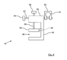
- Figure 4 shows a further arrangement, with the bracket 16 connected so that the arm 14 is in front of the bracket 16.
- the shaft 22 is below the arm 14.
- a still further arrangement is shown in Figure 5 , with shows a view similar to that of Figure 4 , with the fixing portion 20 reversed (rotated 180 degrees), relative to the position shown in Figure 4 .
- FIG 6 shows the apparatus 10 fixed to a vehicle wing mirror 40.
- Each of the clamps 18 of the two brackets 16 mounted on the arm 14 have been rotated in opposite directions about their respective axis's A. This rotation facilitates the fastening of the apparatus to the wing mirror 40.
- the lip of the mirror 40 is fixed between the respective engaging portions 36 of each clamp 18, and the user tightens the clamping member 28 to fasten the towing mirror 10 in place on the wing mirror 40.
Landscapes
- Engineering & Computer Science (AREA)
- Mechanical Engineering (AREA)
- Multimedia (AREA)
- General Engineering & Computer Science (AREA)
- Rear-View Mirror Devices That Are Mounted On The Exterior Of The Vehicle (AREA)
Abstract
Description
- This invention relates to apparatus including a mirror assembly. Such apparatus can be used by vehicle drivers, for example when the driver is towing a wide load and needs an extension to their conventional wing mirror.
- If a vehicle driver is towing a wide load, such as a car with a caravan, then it is advantageous, and in some jurisdictions a legal requirement, that the conventional vehicle wing mirror be extended, in order for the vehicle driver to be able to see behind and along the side of the wide load. To achieve this, it is known to provide apparatus, sometimes referred to as a towing mirror, which includes a mirror and a device for fixing that mirror to the conventional wing mirror. However, as vehicle design becomes more complicated and elaborate, there is a difficulty providing a towing mirror that will fit all, or at least the vast majority, of wing mirror designs.
- It is therefore an object of the invention to improve upon the known art.
- According to a first aspect of the present invention, there is provided apparatus comprising a mirror assembly, an arm connected to the mirror assembly, and a bracket mounted on the arm, the bracket comprising a clamp for connecting to a vehicle wing mirror, characterised in that the clamp is rotatable about an axis substantially perpendicular to the arm.
- Owing to this aspect of the invention, it is possible to provide a bracket which mounts the apparatus (a towing mirror) on virtually all current designs of wing mirror. By being rotatable relative to the arm of the apparatus, the clamp of the bracket can be adjusted to the local shape of the vehicle wing mirror to which it is being fixed.
- Preferably, the apparatus further comprises a second bracket mounted on the arm, the second bracket comprising a clamp for connecting to a vehicle wing mirror, wherein the clamp is rotatable about an axis substantially perpendicular to the arm. The provision of two brackets on the arm provides a towing mirror that can be very securely fastened to a vehicle wing mirror.
- Advantageously, the clamp comprises a frame and a movable clamping member, the clamping member including an engaging portion, the engaging portion is connected to a shaft and is turnably mounted on the shaft, and one of the frame and the engaging portion includes a guiding slot, and the other of the frame and the engaging portion includes a guiding element engaging in the guiding slot.
- According to a second aspect of the present invention, there is provided apparatus comprising a clamp, the clamp comprising a frame and a movable clamping member, the clamping member including an engaging portion, characterised in that one of the frame and the engaging portion includes a guiding slot, and the other of the frame and the engaging portion includes a guiding element engaging in the guiding slot.
- Owing to this aspect of the invention, it is possible to provide a clamp with a guiding arrangement so that the engaging portion of the clamping member is relatively easy to keep on position when the clamp is being opened and closed.
- Embodiments of the present invention will now be described, by way of example only, with reference to the accompanying drawings, in which:-
-
Figure 1 is a front view of apparatus including a mirror assembly, -
Figure 2 is a side view of the apparatus ofFigure 1 , -
Figures 3 to 5 show alternative arrangements of the apparatus ofFigure 2 , and -
Figure 6 is a front view of apparatus ofFigure 1 , in use. -
Figure 1 shows theapparatus 10, which comprising amirror assembly 12, anarm 14 connected to themirror assembly 12, and twobrackets 16 mounted on thearm 14. Eachbracket 16 comprises aclamp 18 for connecting to a vehicle wing mirror (not shown), and eachclamp 18 is rotatable about an axis A, the axis A being substantially perpendicular to thearm 14. Theapparatus 10 is shown with twobrackets 16, as a preferred embodiment, but theapparatus 10 could equally well be provided with only asingle bracket 16. - Each
bracket 16 also includes afixing portion 20 for connecting therespective bracket 16 directly to thearm 14 of theapparatus 10, and ashaft 22 for connecting theclamp 18 to thefixing portion 20. Theclamp 18 is rotatable about theshaft 22. Eachbracket 16 also includes alocking element 24 for preventing rotation of theclamp 20. - The
shaft 22, with thelocking element 24 fixably mounted thereto can be a screw-thread that theclamp 18 will rotate about. Thelocking element 24 can be unscrewed to allow theclamp 18 to be rotated into position, and then thelocking element 24 can be retightened to fix theclamp 18 in position, so that theclamp 18 can no longer move relative to thearm 14. - Since the
apparatus 10 is designed as a towing mirror, a wide variety of different shapes of vehicle wing mirror can have theapparatus 10 fixed thereto. The provision of the rotation of theclamp 18 on eachbracket 16 allows eachclamp 18 to be positioned to best suit the local shape of the vehicle wing mirror to which thebracket 16 is being fixed. In particular, since there are provided twobrackets 16 in the embodiment ofFigure 1 , and both haveclamps 18 that are rotatable independently of each other, a vehicle wing mirror with a varying shape can be connected to, without any impact on the performance of the towing mirror. Such a connection is relatively easy for a user to make themselves without any specialist assistance. - The
apparatus 10 is designed to fit to a wing mirror of a vehicle such as a car. Theapparatus 10 allows the driver of the car to be able to see behind them, by extending themirror assembly 12 out and beyond a wide load that the car may be towing. Thearm 14 of theapparatus 10 extends in the same plane as themirror assembly 12, out to the side of themirror assembly 12, and is at least twice the length of themirror assembly 12. Thearm 14 is also, at least twice as long as thebrackets 16 are wide, so that it can support at least twobrackets 16. Thearm 14 is an elongate rod-like construction, which mounts thebrackets 16 so that they are alongside themirror assembly 12. - Each
clamp 18 comprises aframe 26 and amovable clamping member 28, theclamping member 28 including an engaging portion (shown inFigure 2 ). The engaging portion is connected to ashaft 30 and is turnably mounted on theshaft 30. The frame includes a guidingslot 32, and the engaging portion includes a guidingelement 34 engaging in the guidingslot 32. The purpose of the guidingelement 34 and theslot 32 is to assist in the locating and moving of the engaging portion. -
Figure 2 shows thisengaging portion 36, in a side view of theapparatus 10 ofFigure 1 , with themirror assembly 12 removed for clarity. Thebracket 16 comprises theclamp 18, thefixing portion 20 and theshaft 22. Theclamp 18 can turn about theshaft 22, and thelocking element 24 is used to tighten theclamp 18 against thefixing portion 20, when the correct position has been chosen by a user. - The user turns the
shaft 30 via the knob of theclamping member 28 and this raises and lowers theengaging portion 36, which is loosely mounted on theshaft 30. This allows theengaging portion 36 to move in such away that the bottom surface of theportion 36 is no longer horizontal. The guidingelement 34 can be seen engaging with the slot of the g-clamp 18. Since theengaging portion 36 is moveable on the end of theshaft 30, the guiding arrangement assists the user in the locating of the bracket on the vehicle wing mirror. Thegap 38 inFigure 2 shows where a vehicle wing mirror would be secured by theclamp 18. Theclamp 18 forms part of thebracket 16, thebracket 16 for connecting themirror assembly 12 to a vehicle wing mirror. -
Figure 3 shows thebracket 16 mounted on thearm 14 in a manner different from that shown inFigure 2 . In this arrangement, theshaft 22 is mounted above thearm 14, with thefixing portion 20 reversed (rotated 180 degrees), relative to the position inFigure 2 . The design of thebracket 16 is such that a wide variety of different connection arrangements are possible, to suit the user, and design of wing mirror, to which thebracket 16 is being fixed.Figure 4 shows a further arrangement, with thebracket 16 connected so that thearm 14 is in front of thebracket 16. Theshaft 22 is below thearm 14. A still further arrangement is shown inFigure 5 , with shows a view similar to that ofFigure 4 , with thefixing portion 20 reversed (rotated 180 degrees), relative to the position shown inFigure 4 . -
Figure 6 shows theapparatus 10 fixed to avehicle wing mirror 40. Each of theclamps 18 of the twobrackets 16 mounted on thearm 14 have been rotated in opposite directions about their respective axis's A. This rotation facilitates the fastening of the apparatus to thewing mirror 40. The lip of themirror 40 is fixed between the respectiveengaging portions 36 of eachclamp 18, and the user tightens theclamping member 28 to fasten thetowing mirror 10 in place on thewing mirror 40.
Claims (10)
- Apparatus comprising• a mirror assembly (12),• an arm (14) connected to the mirror assembly (12), and• a bracket (16) mounted on the arm (14), the bracket (16) comprising a clamp (18) for connecting to a vehicle wing mirror (40),characterised in that the clamp (18) is rotatable about an axis (A) substantially perpendicular to the arm (14).
- Apparatus according to claim 1, wherein the bracket (16) includes a fixing portion (20) for connecting to the arm (14) and a shaft (22) connecting the clamp (18) to the fixing portion (20).
- Apparatus according to claim 2, wherein the clamp (18) is rotatable about the shaft (22).
- Apparatus according to claim 1, 2 or 3, wherein the bracket (16) includes a locking element (24) for preventing rotation of the clamp (18).
- Apparatus according to any preceding claim, wherein the clamp (18) comprises a frame (26) and a movable clamping member (28), the clamping member (28) including an engaging portion (36).
- Apparatus according to claim 5, wherein the engaging portion (36) is connected to a shaft (30) and is turnably mounted on the shaft (30).
- Apparatus according to claim 5 or 6, wherein one of the frame (26) and the engaging portion (36) includes a guiding slot (32), and the other of the frame (26) and the engaging portion (36) includes a guiding element (34) engaging in the guiding slot (32).
- Apparatus according to any preceding claim, and further comprising a second bracket (16) mounted on the arm (14), the second bracket (16) comprising a clamp (18) for connecting to a vehicle wing mirror (40), wherein the clamp (18) is rotatable about an axis (A) substantially perpendicular to the arm (14).
- Apparatus comprising a clamp (18), the clamp (18) comprising a frame (26) and a movable clamping member (28), the clamping member (28) including an engaging portion (36), characterised in that one of the frame (26) and the engaging portion (36) includes a guiding slot (32), and the other of the frame (26) and the engaging portion (36) includes a guiding element (34) engaging in the guiding slot (32).
- Apparatus according to claim 9, wherein the engaging portion (36) is connected to a shaft (30) and is turnably mounted on the shaft (30).
Priority Applications (2)
| Application Number | Priority Date | Filing Date | Title |
|---|---|---|---|
| EP15190842.3A EP2998160B1 (en) | 2006-12-20 | 2007-12-17 | Method of fixing an apparatus comprising a towing mirror |
| DK15190842.3T DK2998160T3 (en) | 2006-12-20 | 2007-12-17 | PROCEDURE TO FIX A DEVICE CONTAINING A TRAILER MIRROR. |
Applications Claiming Priority (1)
| Application Number | Priority Date | Filing Date | Title |
|---|---|---|---|
| GB0625340A GB2444919B (en) | 2006-12-20 | 2006-12-20 | Apparatus including a mirror assembly |
Related Child Applications (2)
| Application Number | Title | Priority Date | Filing Date |
|---|---|---|---|
| EP15190842.3A Division EP2998160B1 (en) | 2006-12-20 | 2007-12-17 | Method of fixing an apparatus comprising a towing mirror |
| EP15190842.3A Division-Into EP2998160B1 (en) | 2006-12-20 | 2007-12-17 | Method of fixing an apparatus comprising a towing mirror |
Publications (3)
| Publication Number | Publication Date |
|---|---|
| EP1935718A2 true EP1935718A2 (en) | 2008-06-25 |
| EP1935718A3 EP1935718A3 (en) | 2012-06-13 |
| EP1935718B1 EP1935718B1 (en) | 2015-12-09 |
Family
ID=37712434
Family Applications (2)
| Application Number | Title | Priority Date | Filing Date |
|---|---|---|---|
| EP07024372.0A Active EP1935718B1 (en) | 2006-12-20 | 2007-12-17 | Apparatus including a mirror assembly |
| EP15190842.3A Active EP2998160B1 (en) | 2006-12-20 | 2007-12-17 | Method of fixing an apparatus comprising a towing mirror |
Family Applications After (1)
| Application Number | Title | Priority Date | Filing Date |
|---|---|---|---|
| EP15190842.3A Active EP2998160B1 (en) | 2006-12-20 | 2007-12-17 | Method of fixing an apparatus comprising a towing mirror |
Country Status (4)
| Country | Link |
|---|---|
| EP (2) | EP1935718B1 (en) |
| DK (2) | DK2998160T3 (en) |
| ES (1) | ES2720297T3 (en) |
| GB (1) | GB2444919B (en) |
Cited By (6)
| Publication number | Priority date | Publication date | Assignee | Title |
|---|---|---|---|---|
| NL2003077C2 (en) * | 2009-06-24 | 2010-12-27 | Adrianus Jacobus Peter Dooren | VIBRATION-FREE HELP MIRROR. |
| DE202012008084U1 (en) | 2011-09-30 | 2012-09-12 | Brunsgaard Aps | Camping mirror holder |
| EP2826672A1 (en) | 2013-07-16 | 2015-01-21 | Reich KG | Mirror assembly with adjustable fastening |
| EP2860064A1 (en) * | 2013-10-09 | 2015-04-15 | Milenco Limited | A clamp |
| EP2998160A1 (en) | 2006-12-20 | 2016-03-23 | Milenco Limited | Apparatus including a mirror assembly |
| IT201900004293A1 (en) * | 2019-03-25 | 2020-09-25 | Brunner Srl | Rear-view device for displaying images that can be associated with a rear-view mirror of a vehicle |
Families Citing this family (4)
| Publication number | Priority date | Publication date | Assignee | Title |
|---|---|---|---|---|
| GB2488775B (en) * | 2011-03-05 | 2013-05-08 | Milenco Ltd | Towing mirror clamp |
| AU355255S (en) | 2013-10-09 | 2014-05-02 | Milenco Ltd | Towing mirror |
| DE202015005970U1 (en) | 2015-08-27 | 2015-12-07 | Milenco Limited | Improved gripping pad for additional external mirror clamp |
| GB2598620B (en) | 2020-09-07 | 2022-12-14 | Milenco Ltd | Enhanced flexible gripper pad for towing mirror clamp |
Citations (2)
| Publication number | Priority date | Publication date | Assignee | Title |
|---|---|---|---|---|
| DE3411631C1 (en) | 1984-03-29 | 1985-09-26 | Daimler-Benz Ag, 7000 Stuttgart | Additional mirror which can be placed on the casing of an outside mirror of a vehicle |
| EP0437695A1 (en) | 1990-01-16 | 1991-07-24 | HAGUS C. LUCHTENBERG GmbH & Co. KG | Auxiliary external mirror for motor vehicles |
Family Cites Families (16)
| Publication number | Priority date | Publication date | Assignee | Title |
|---|---|---|---|---|
| US1760346A (en) * | 1928-12-12 | 1930-05-27 | Frank M Correa | Bedding clamp |
| US4486075A (en) * | 1982-09-27 | 1984-12-04 | Cohen Stephen R | Mirror assembly for a vehicle |
| DE8802554U1 (en) * | 1988-02-26 | 1988-04-14 | Aerolux H.-J. Mähl Inh. Karl Metz, 2000 Norderstedt | Clamp bracket for sun protection devices |
| US4794675A (en) * | 1988-04-01 | 1989-01-03 | Bisconti Edward M | Adjustable clamp with slot and guide |
| GB2240309B (en) * | 1990-01-24 | 1993-09-22 | Devendra Prabhudas Dolasia | A driving mirror |
| FR2661479B3 (en) * | 1990-04-26 | 1992-08-14 | Bicc Ltd | SUPPORTS FOR CABLE AND EXTENDED BODIES. |
| NL192258C (en) * | 1990-12-19 | 1997-04-03 | Repusel B V | Additional exterior mirror device and assembly of a substantially stretchless woven tape intended for such a device. |
| US5165081A (en) * | 1991-07-29 | 1992-11-17 | Drumheller Dennis W | Auxiliary clamp-on mirror |
| US5870236A (en) * | 1997-05-02 | 1999-02-09 | Barksdale; Brian | Towing mirror extension |
| US6132051A (en) * | 1998-12-03 | 2000-10-17 | Morell; Kenneth | Mirror attachment |
| NL1019938C2 (en) * | 2002-02-11 | 2003-08-13 | Reich Kg | Mirror assembly. |
| FR2870901A1 (en) * | 2004-05-28 | 2005-12-02 | Pierre Dubost Sa | Object e.g. suspension spindle, fixing staple for display unit support, has rear flange mounted movable with respect to front flange receiving suspension spindle, and adjusting unit to adjust distance between rear flange and front flange |
| DE602005005819T2 (en) * | 2005-09-21 | 2009-04-30 | Hu, Tsai-Fu, Yung Kang | Mounting arrangement for additional rearview mirror |
| DE202005016734U1 (en) * | 2005-10-25 | 2005-12-29 | Liou, Ferng-Jong, Wu Jih | Clamping and holding device for workpiece, has control handle having nut screwed to threaded rod of adjusting knob, such that nut moves along threaded rod when adjusting knob is rotated to move mobile support jaw along guide rod |
| GB2439953A (en) * | 2006-07-08 | 2008-01-16 | Alan Whitby | Clamping apparatus for locating building floor channels |
| GB2444919B (en) | 2006-12-20 | 2009-04-22 | Milenco Ltd | Apparatus including a mirror assembly |
-
2006
- 2006-12-20 GB GB0625340A patent/GB2444919B/en active Active
-
2007
- 2007-12-17 EP EP07024372.0A patent/EP1935718B1/en active Active
- 2007-12-17 EP EP15190842.3A patent/EP2998160B1/en active Active
- 2007-12-17 ES ES15190842T patent/ES2720297T3/en active Active
- 2007-12-17 DK DK15190842.3T patent/DK2998160T3/en active
- 2007-12-17 DK DK07024372.0T patent/DK1935718T3/en active
Patent Citations (2)
| Publication number | Priority date | Publication date | Assignee | Title |
|---|---|---|---|---|
| DE3411631C1 (en) | 1984-03-29 | 1985-09-26 | Daimler-Benz Ag, 7000 Stuttgart | Additional mirror which can be placed on the casing of an outside mirror of a vehicle |
| EP0437695A1 (en) | 1990-01-16 | 1991-07-24 | HAGUS C. LUCHTENBERG GmbH & Co. KG | Auxiliary external mirror for motor vehicles |
Cited By (8)
| Publication number | Priority date | Publication date | Assignee | Title |
|---|---|---|---|---|
| EP2998160A1 (en) | 2006-12-20 | 2016-03-23 | Milenco Limited | Apparatus including a mirror assembly |
| NL2003077C2 (en) * | 2009-06-24 | 2010-12-27 | Adrianus Jacobus Peter Dooren | VIBRATION-FREE HELP MIRROR. |
| DE202012008084U1 (en) | 2011-09-30 | 2012-09-12 | Brunsgaard Aps | Camping mirror holder |
| EP2826672A1 (en) | 2013-07-16 | 2015-01-21 | Reich KG | Mirror assembly with adjustable fastening |
| NL2011171C2 (en) * | 2013-07-16 | 2015-01-21 | Reich Kg | MIRROR COMPOSITION WITH ADJUSTABLE CONFIRMATION. |
| US9766428B2 (en) | 2013-07-16 | 2017-09-19 | David Smith | Mirror assembly with adjustable fastening |
| EP2860064A1 (en) * | 2013-10-09 | 2015-04-15 | Milenco Limited | A clamp |
| IT201900004293A1 (en) * | 2019-03-25 | 2020-09-25 | Brunner Srl | Rear-view device for displaying images that can be associated with a rear-view mirror of a vehicle |
Also Published As
| Publication number | Publication date |
|---|---|
| GB2444919A (en) | 2008-06-25 |
| EP2998160B1 (en) | 2019-01-16 |
| DK1935718T3 (en) | 2016-02-29 |
| EP1935718B1 (en) | 2015-12-09 |
| EP1935718A3 (en) | 2012-06-13 |
| DK2998160T3 (en) | 2019-05-06 |
| ES2720297T3 (en) | 2019-07-19 |
| GB2444919B (en) | 2009-04-22 |
| EP2998160A1 (en) | 2016-03-23 |
| GB0625340D0 (en) | 2007-01-24 |
Similar Documents
| Publication | Publication Date | Title |
|---|---|---|
| EP2998160B1 (en) | Method of fixing an apparatus comprising a towing mirror | |
| US8814373B2 (en) | Rearview device support assembly | |
| BRPI0620919A2 (en) | windshield wiper device, in particular, for a self-propelled vehicle | |
| EP2860064B1 (en) | A clamp | |
| JP2006145895A (en) | Camera universal head | |
| EP1514732A1 (en) | Rear view mirror assembly for vehicles, in particular for commercial vehicles | |
| US10625690B2 (en) | Vehicle ceiling connecting arrangement | |
| JP4891663B2 (en) | Door mirror mounting structure | |
| US6398376B2 (en) | Side break-away rear view mirror assembly with telescopic support brace | |
| GB2481626A (en) | Gripper pad for vehicle towing mirror | |
| EP1813476A2 (en) | Arrangement for lorries for mounting accessories, in particular lamps | |
| US9766428B2 (en) | Mirror assembly with adjustable fastening | |
| RU2767391C2 (en) | Fastening device, in particular for a display device in a vehicle | |
| US7828452B2 (en) | Vehicle mirror support assembly with cast brace | |
| GB2300669A (en) | Motor vehicle door or tailgate hinge | |
| GB2488775A (en) | Towing mirror clamp assembly | |
| KR100934779B1 (en) | Side mirrors device of the vehicles for the rainwater elimination | |
| GB2529687A (en) | Improved gripper pad for towing mirror clamp | |
| EP1020326B1 (en) | Clamp for mounting rear view mirrors | |
| US10583876B2 (en) | Device for fixing an air-guiding means to a motor vehicle | |
| EP0094187A2 (en) | Exterior rear-view mirrors | |
| JP2002019535A (en) | Fitting structure for on-vehicle image pickup device | |
| JP4156404B2 (en) | Fastener | |
| CN110154953A (en) | Block terminal mounting bracket and automobile | |
| JP4335281B2 (en) | Seat, in particular vehicle seat, and manufacturing method thereof |
Legal Events
| Date | Code | Title | Description |
|---|---|---|---|
| PUAI | Public reference made under article 153(3) epc to a published international application that has entered the european phase |
Free format text: ORIGINAL CODE: 0009012 |
|
| AK | Designated contracting states |
Kind code of ref document: A2 Designated state(s): AT BE BG CH CY CZ DE DK EE ES FI FR GB GR HU IE IS IT LI LT LU LV MC MT NL PL PT RO SE SI SK TR |
|
| AX | Request for extension of the european patent |
Extension state: AL BA HR MK RS |
|
| PUAL | Search report despatched |
Free format text: ORIGINAL CODE: 0009013 |
|
| AK | Designated contracting states |
Kind code of ref document: A3 Designated state(s): AT BE BG CH CY CZ DE DK EE ES FI FR GB GR HU IE IS IT LI LT LU LV MC MT NL PL PT RO SE SI SK TR |
|
| AX | Request for extension of the european patent |
Extension state: AL BA HR MK RS |
|
| RIC1 | Information provided on ipc code assigned before grant |
Ipc: B60R 1/00 20060101AFI20120504BHEP |
|
| AKY | No designation fees paid | ||
| REG | Reference to a national code |
Ref country code: DE Ref legal event code: R108 |
|
| REG | Reference to a national code |
Ref country code: DE Ref legal event code: R108 Ref document number: 602007044152 Country of ref document: DE Effective date: 20130220 Ref country code: DE Ref legal event code: R108 Effective date: 20130220 |
|
| 17P | Request for examination filed |
Effective date: 20121214 |
|
| RBV | Designated contracting states (corrected) |
Designated state(s): AT BE BG CH CY CZ DE DK EE ES FI FR GB GR HU IE IS IT LI LT LU LV MC MT NL PL PT RO SE SI SK TR |
|
| 17Q | First examination report despatched |
Effective date: 20130510 |
|
| TPAC | Observations filed by third parties |
Free format text: ORIGINAL CODE: EPIDOSNTIPA |
|
| TPAA | Information related to observations by third parties modified |
Free format text: ORIGINAL CODE: EPIDOSCTIPA |
|
| GRAP | Despatch of communication of intention to grant a patent |
Free format text: ORIGINAL CODE: EPIDOSNIGR1 |
|
| GRAJ | Information related to disapproval of communication of intention to grant by the applicant or resumption of examination proceedings by the epo deleted |
Free format text: ORIGINAL CODE: EPIDOSDIGR1 |
|
| INTG | Intention to grant announced |
Effective date: 20140515 |
|
| INTC | Intention to grant announced (deleted) | ||
| GRAP | Despatch of communication of intention to grant a patent |
Free format text: ORIGINAL CODE: EPIDOSNIGR1 |
|
| INTG | Intention to grant announced |
Effective date: 20150625 |
|
| GRAS | Grant fee paid |
Free format text: ORIGINAL CODE: EPIDOSNIGR3 |
|
| GRAA | (expected) grant |
Free format text: ORIGINAL CODE: 0009210 |
|
| RBV | Designated contracting states (corrected) |
Designated state(s): AT BE BG CH CY CZ DE DK EE ES FI FR GR HU IE IS IT LI LT LU LV MC MT NL PL PT RO SE SI SK TR |
|
| AK | Designated contracting states |
Kind code of ref document: B1 Designated state(s): AT BE BG CH CY CZ DE DK EE ES FI FR GR HU IE IS IT LI LT LU LV MC MT NL PL PT RO SE SI SK TR |
|
| REG | Reference to a national code |
Ref country code: AT Ref legal event code: REF Ref document number: 764414 Country of ref document: AT Kind code of ref document: T Effective date: 20151215 Ref country code: CH Ref legal event code: EP |
|
| REG | Reference to a national code |
Ref country code: IE Ref legal event code: FG4D |
|
| REG | Reference to a national code |
Ref country code: DE Ref legal event code: R096 Ref document number: 602007044152 Country of ref document: DE |
|
| REG | Reference to a national code |
Ref country code: FR Ref legal event code: PLFP Year of fee payment: 9 |
|
| REG | Reference to a national code |
Ref country code: DK Ref legal event code: T3 Effective date: 20160223 |
|
| REG | Reference to a national code |
Ref country code: SE Ref legal event code: TRGR |
|
| REG | Reference to a national code |
Ref country code: NL Ref legal event code: FP |
|
| REG | Reference to a national code |
Ref country code: LT Ref legal event code: MG4D |
|
| PG25 | Lapsed in a contracting state [announced via postgrant information from national office to epo] |
Ref country code: LT Free format text: LAPSE BECAUSE OF FAILURE TO SUBMIT A TRANSLATION OF THE DESCRIPTION OR TO PAY THE FEE WITHIN THE PRESCRIBED TIME-LIMIT Effective date: 20151209 Ref country code: ES Free format text: LAPSE BECAUSE OF FAILURE TO SUBMIT A TRANSLATION OF THE DESCRIPTION OR TO PAY THE FEE WITHIN THE PRESCRIBED TIME-LIMIT Effective date: 20151209 |
|
| REG | Reference to a national code |
Ref country code: AT Ref legal event code: MK05 Ref document number: 764414 Country of ref document: AT Kind code of ref document: T Effective date: 20151209 |
|
| PG25 | Lapsed in a contracting state [announced via postgrant information from national office to epo] |
Ref country code: FI Free format text: LAPSE BECAUSE OF FAILURE TO SUBMIT A TRANSLATION OF THE DESCRIPTION OR TO PAY THE FEE WITHIN THE PRESCRIBED TIME-LIMIT Effective date: 20151209 Ref country code: LV Free format text: LAPSE BECAUSE OF FAILURE TO SUBMIT A TRANSLATION OF THE DESCRIPTION OR TO PAY THE FEE WITHIN THE PRESCRIBED TIME-LIMIT Effective date: 20151209 Ref country code: GR Free format text: LAPSE BECAUSE OF FAILURE TO SUBMIT A TRANSLATION OF THE DESCRIPTION OR TO PAY THE FEE WITHIN THE PRESCRIBED TIME-LIMIT Effective date: 20160310 Ref country code: BE Free format text: LAPSE BECAUSE OF NON-PAYMENT OF DUE FEES Effective date: 20151231 |
|
| PG25 | Lapsed in a contracting state [announced via postgrant information from national office to epo] |
Ref country code: IS Free format text: LAPSE BECAUSE OF FAILURE TO SUBMIT A TRANSLATION OF THE DESCRIPTION OR TO PAY THE FEE WITHIN THE PRESCRIBED TIME-LIMIT Effective date: 20151209 |
|
| PG25 | Lapsed in a contracting state [announced via postgrant information from national office to epo] |
Ref country code: CZ Free format text: LAPSE BECAUSE OF FAILURE TO SUBMIT A TRANSLATION OF THE DESCRIPTION OR TO PAY THE FEE WITHIN THE PRESCRIBED TIME-LIMIT Effective date: 20151209 Ref country code: IT Free format text: LAPSE BECAUSE OF FAILURE TO SUBMIT A TRANSLATION OF THE DESCRIPTION OR TO PAY THE FEE WITHIN THE PRESCRIBED TIME-LIMIT Effective date: 20151209 |
|
| REG | Reference to a national code |
Ref country code: CH Ref legal event code: PL |
|
| PG25 | Lapsed in a contracting state [announced via postgrant information from national office to epo] |
Ref country code: EE Free format text: LAPSE BECAUSE OF FAILURE TO SUBMIT A TRANSLATION OF THE DESCRIPTION OR TO PAY THE FEE WITHIN THE PRESCRIBED TIME-LIMIT Effective date: 20151209 Ref country code: IS Free format text: LAPSE BECAUSE OF FAILURE TO SUBMIT A TRANSLATION OF THE DESCRIPTION OR TO PAY THE FEE WITHIN THE PRESCRIBED TIME-LIMIT Effective date: 20160409 Ref country code: RO Free format text: LAPSE BECAUSE OF FAILURE TO SUBMIT A TRANSLATION OF THE DESCRIPTION OR TO PAY THE FEE WITHIN THE PRESCRIBED TIME-LIMIT Effective date: 20151209 Ref country code: AT Free format text: LAPSE BECAUSE OF FAILURE TO SUBMIT A TRANSLATION OF THE DESCRIPTION OR TO PAY THE FEE WITHIN THE PRESCRIBED TIME-LIMIT Effective date: 20151209 Ref country code: PT Free format text: LAPSE BECAUSE OF FAILURE TO SUBMIT A TRANSLATION OF THE DESCRIPTION OR TO PAY THE FEE WITHIN THE PRESCRIBED TIME-LIMIT Effective date: 20160411 Ref country code: SK Free format text: LAPSE BECAUSE OF FAILURE TO SUBMIT A TRANSLATION OF THE DESCRIPTION OR TO PAY THE FEE WITHIN THE PRESCRIBED TIME-LIMIT Effective date: 20151209 |
|
| REG | Reference to a national code |
Ref country code: DE Ref legal event code: R026 Ref document number: 602007044152 Country of ref document: DE |
|
| PLBI | Opposition filed |
Free format text: ORIGINAL CODE: 0009260 |
|
| REG | Reference to a national code |
Ref country code: IE Ref legal event code: MM4A |
|
| PG25 | Lapsed in a contracting state [announced via postgrant information from national office to epo] |
Ref country code: MC Free format text: LAPSE BECAUSE OF FAILURE TO SUBMIT A TRANSLATION OF THE DESCRIPTION OR TO PAY THE FEE WITHIN THE PRESCRIBED TIME-LIMIT Effective date: 20151209 |
|
| PLAX | Notice of opposition and request to file observation + time limit sent |
Free format text: ORIGINAL CODE: EPIDOSNOBS2 |
|
| 26 | Opposition filed |
Opponent name: BRUNSGAARD.EU APS Effective date: 20160909 |
|
| PG25 | Lapsed in a contracting state [announced via postgrant information from national office to epo] |
Ref country code: IE Free format text: LAPSE BECAUSE OF NON-PAYMENT OF DUE FEES Effective date: 20151217 Ref country code: PL Free format text: LAPSE BECAUSE OF FAILURE TO SUBMIT A TRANSLATION OF THE DESCRIPTION OR TO PAY THE FEE WITHIN THE PRESCRIBED TIME-LIMIT Effective date: 20151209 Ref country code: LI Free format text: LAPSE BECAUSE OF NON-PAYMENT OF DUE FEES Effective date: 20151231 Ref country code: CH Free format text: LAPSE BECAUSE OF NON-PAYMENT OF DUE FEES Effective date: 20151231 |
|
| PG25 | Lapsed in a contracting state [announced via postgrant information from national office to epo] |
Ref country code: SI Free format text: LAPSE BECAUSE OF FAILURE TO SUBMIT A TRANSLATION OF THE DESCRIPTION OR TO PAY THE FEE WITHIN THE PRESCRIBED TIME-LIMIT Effective date: 20151209 |
|
| REG | Reference to a national code |
Ref country code: FR Ref legal event code: PLFP Year of fee payment: 10 |
|
| PG25 | Lapsed in a contracting state [announced via postgrant information from national office to epo] |
Ref country code: BE Free format text: LAPSE BECAUSE OF FAILURE TO SUBMIT A TRANSLATION OF THE DESCRIPTION OR TO PAY THE FEE WITHIN THE PRESCRIBED TIME-LIMIT Effective date: 20151209 |
|
| PLBB | Reply of patent proprietor to notice(s) of opposition received |
Free format text: ORIGINAL CODE: EPIDOSNOBS3 |
|
| PG25 | Lapsed in a contracting state [announced via postgrant information from national office to epo] |
Ref country code: BG Free format text: LAPSE BECAUSE OF FAILURE TO SUBMIT A TRANSLATION OF THE DESCRIPTION OR TO PAY THE FEE WITHIN THE PRESCRIBED TIME-LIMIT Effective date: 20151209 Ref country code: HU Free format text: LAPSE BECAUSE OF FAILURE TO SUBMIT A TRANSLATION OF THE DESCRIPTION OR TO PAY THE FEE WITHIN THE PRESCRIBED TIME-LIMIT; INVALID AB INITIO Effective date: 20071217 |
|
| PG25 | Lapsed in a contracting state [announced via postgrant information from national office to epo] |
Ref country code: CY Free format text: LAPSE BECAUSE OF FAILURE TO SUBMIT A TRANSLATION OF THE DESCRIPTION OR TO PAY THE FEE WITHIN THE PRESCRIBED TIME-LIMIT Effective date: 20151209 |
|
| PG25 | Lapsed in a contracting state [announced via postgrant information from national office to epo] |
Ref country code: MT Free format text: LAPSE BECAUSE OF FAILURE TO SUBMIT A TRANSLATION OF THE DESCRIPTION OR TO PAY THE FEE WITHIN THE PRESCRIBED TIME-LIMIT Effective date: 20151209 Ref country code: TR Free format text: LAPSE BECAUSE OF FAILURE TO SUBMIT A TRANSLATION OF THE DESCRIPTION OR TO PAY THE FEE WITHIN THE PRESCRIBED TIME-LIMIT Effective date: 20151209 |
|
| PG25 | Lapsed in a contracting state [announced via postgrant information from national office to epo] |
Ref country code: LU Free format text: LAPSE BECAUSE OF NON-PAYMENT OF DUE FEES Effective date: 20151217 |
|
| REG | Reference to a national code |
Ref country code: FR Ref legal event code: PLFP Year of fee payment: 11 |
|
| REG | Reference to a national code |
Ref country code: DE Ref legal event code: R100 Ref document number: 602007044152 Country of ref document: DE |
|
| PLCK | Communication despatched that opposition was rejected |
Free format text: ORIGINAL CODE: EPIDOSNREJ1 |
|
| PLBN | Opposition rejected |
Free format text: ORIGINAL CODE: 0009273 |
|
| STAA | Information on the status of an ep patent application or granted ep patent |
Free format text: STATUS: OPPOSITION REJECTED |
|
| 27O | Opposition rejected |
Effective date: 20180412 |
|
| PGFP | Annual fee paid to national office [announced via postgrant information from national office to epo] |
Ref country code: SE Payment date: 20231215 Year of fee payment: 17 Ref country code: NL Payment date: 20231228 Year of fee payment: 17 Ref country code: FR Payment date: 20231219 Year of fee payment: 17 Ref country code: DK Payment date: 20231219 Year of fee payment: 17 |
|
| PGFP | Annual fee paid to national office [announced via postgrant information from national office to epo] |
Ref country code: DE Payment date: 20231222 Year of fee payment: 17 |