EP2860045A1 - Ball pen - Google Patents
Ball pen Download PDFInfo
- Publication number
- EP2860045A1 EP2860045A1 EP13800078.1A EP13800078A EP2860045A1 EP 2860045 A1 EP2860045 A1 EP 2860045A1 EP 13800078 A EP13800078 A EP 13800078A EP 2860045 A1 EP2860045 A1 EP 2860045A1
- Authority
- EP
- European Patent Office
- Prior art keywords
- writing
- tip end
- outer member
- ball
- tip
- Prior art date
- Legal status (The legal status is an assumption and is not a legal conclusion. Google has not performed a legal analysis and makes no representation as to the accuracy of the status listed.)
- Granted
Links
Images









Classifications
-
- B—PERFORMING OPERATIONS; TRANSPORTING
- B43—WRITING OR DRAWING IMPLEMENTS; BUREAU ACCESSORIES
- B43K—IMPLEMENTS FOR WRITING OR DRAWING
- B43K1/00—Nibs; Writing-points
- B43K1/08—Nibs; Writing-points with ball points; Balls or ball beds
- B43K1/082—Balls
-
- B—PERFORMING OPERATIONS; TRANSPORTING
- B43—WRITING OR DRAWING IMPLEMENTS; BUREAU ACCESSORIES
- B43K—IMPLEMENTS FOR WRITING OR DRAWING
- B43K1/00—Nibs; Writing-points
- B43K1/08—Nibs; Writing-points with ball points; Balls or ball beds
-
- B—PERFORMING OPERATIONS; TRANSPORTING
- B43—WRITING OR DRAWING IMPLEMENTS; BUREAU ACCESSORIES
- B43K—IMPLEMENTS FOR WRITING OR DRAWING
- B43K23/00—Holders or connectors for writing implements; Means for protecting the writing-points
- B43K23/08—Protecting means, e.g. caps
- B43K23/12—Protecting means, e.g. caps for pens
-
- B—PERFORMING OPERATIONS; TRANSPORTING
- B43—WRITING OR DRAWING IMPLEMENTS; BUREAU ACCESSORIES
- B43K—IMPLEMENTS FOR WRITING OR DRAWING
- B43K24/00—Mechanisms for selecting, projecting, retracting or locking writing units
- B43K24/02—Mechanisms for selecting, projecting, retracting or locking writing units for locking a single writing unit in only fully projected or retracted positions
- B43K24/023—Mechanisms for selecting, projecting, retracting or locking writing units for locking a single writing unit in only fully projected or retracted positions with a deformable barrel
-
- B—PERFORMING OPERATIONS; TRANSPORTING
- B43—WRITING OR DRAWING IMPLEMENTS; BUREAU ACCESSORIES
- B43K—IMPLEMENTS FOR WRITING OR DRAWING
- B43K7/00—Ball-point pens
-
- B—PERFORMING OPERATIONS; TRANSPORTING
- B43—WRITING OR DRAWING IMPLEMENTS; BUREAU ACCESSORIES
- B43K—IMPLEMENTS FOR WRITING OR DRAWING
- B43K7/00—Ball-point pens
- B43K7/005—Pen barrels
-
- B—PERFORMING OPERATIONS; TRANSPORTING
- B43—WRITING OR DRAWING IMPLEMENTS; BUREAU ACCESSORIES
- B43K—IMPLEMENTS FOR WRITING OR DRAWING
- B43K7/00—Ball-point pens
- B43K7/02—Ink reservoirs; Ink cartridges
-
- B—PERFORMING OPERATIONS; TRANSPORTING
- B43—WRITING OR DRAWING IMPLEMENTS; BUREAU ACCESSORIES
- B43K—IMPLEMENTS FOR WRITING OR DRAWING
- B43K7/00—Ball-point pens
- B43K7/10—Arrangements for feeding ink to the ball points
-
- B—PERFORMING OPERATIONS; TRANSPORTING
- B43—WRITING OR DRAWING IMPLEMENTS; BUREAU ACCESSORIES
- B43K—IMPLEMENTS FOR WRITING OR DRAWING
- B43K7/00—Ball-point pens
- B43K7/12—Ball-point pens with retractable ball points
Definitions
- the present invention relates to a ballpoint pen capable of changing the width of drawn lines.
- Patent Literature 1 As a technique related to a ballpoint pen capable of writing drawn lines having different widths using one writing shaft, as disclosed in Patent Literature 1, a technique of controlling the amount of ink leakage using a pressurizing mechanism provided in a rear end portion in a shaft tube to change a width and a thickness of a drawn line is known.
- Patent Literature 2 a technique of changing the width and thickness of drawn lines using a ballpoint pen in which pen tips having different ball diameters are attached to both ends of a writing shaft is also known.
- Patent Literature 3 a technique of providing a spring inside a holder so that a writing ball is always pressed toward the writing tip by the resilience of the spring and allowing lines of different widths to be drawn according to a writing load is known. Moreover, a writing instrument capable of moving a marking surface portion back and forth and writing a plurality of narrow and bold lines is also disclosed.
- Patent Literature 1 since a pressurizing mechanism is provided in a writing instrument, the writing instrument has a complex structure. Thus, it is difficult to adjust the pressing force of the pressurizing mechanism during writing, and a redundant amount of ink may leak.
- Patent Literature 2 since only two types of pen tips are used in addition to the inconvenience to invert the writing shaft, it is possible to draw bold and narrow lines only. However, it is not possible to adjust the width of drawn lines.
- an object of the present invention is to provide a ballpoint pen which has a simple structure and which can write drawn lines of different widths using one writing tip without requiring special operations during writing and freely change the width of drawn lines.
- Patent Literature 4 since lines are drawn using the surface of a component, it is difficult to provide smooth writing performance. Moreover, when a shiftable pin is replaced with a pen tip having a writing ball in order to provide smooth writing performance, ink leaking from the gap of the pen tip does not reach the marking surface portion. Thus, it is difficult to write narrow and bold lines having a plurality of widths.
- another object of the present invention is to provide a ballpoint pen which can write drawn lines of different widths using one writing ball and a writing portion made up of two components while maintaining an optimal positional relation between a writing ball and a holder, freely change the width of drawn lines, and easily write characteristic drawn lines with strokes such as "stop,” "hook,” and "fade.”
- the present invention has the following configurations.
- a first aspect of the present invention is a ballpoint pen configured to be capable of writing drawn lines of different widths using one writing tip.
- a second aspect of the present invention includes the following configuration in addition to the configuration of the first aspect of the invention. That is, the ballpoint pen includes: a writing ball; a holder that holds the writing ball by a narrowed portion with a narrowed tip end; an ink supply portion that supplies ink to the holder; a shaft tube that stores the ink supply portion therein; and an outer member that covers an outer circumference of the holder, wherein a part of the holder holding the writing ball and a part of the outer member are exposed from a tip end portion of the shaft tube, and the writing ball and an outer member tip end portion form a writing portion.
- the shaft tube may be configured to capably store ink therein directly and may be configured to store a refill in which ink is filled.
- the ink supply portion may be configured to supply ink stored in the shaft tube to the holder with the aid of an intermediate member such as a collector and may be configured to supply ink stored in an ink storage tube such as a refill which is separated from the shaft tube to the holder.
- the holder has a tip end which is exposed from the tip end portion (front shaft portion) of the shaft tube and has a rear end which is positioned inside the shaft tube and communicates with the ink supply portion.
- a ball house is formed in the tip end of the holder, and the writing ball is held in the ball house.
- the holder can be formed by cutting or injection-molding a metal material such as stainless steel or a resin material such as polyacetal.
- the outer member is a tubular member that covers at least a portion of the holder exposed from the shaft tube and is preferably formed from a synthetic resin.
- the holder is covered with the outer member and only the narrowed portion is exposed from the outer member.
- the outer member tip end portion is a tip end portion of the outer member and is configured to capably make contact with the writing surface substantially simultaneously with the writing ball. That is, the outer member tip end portion swells further toward the outer side (the outer circumference) than the narrowed portion, and the narrowed portion is at the same position as the tangent that touches both the writing ball and the outer member tip end portion or does not protrude toward the tip end.
- the ballpoint pen when a user writes lines in a state where the shaft tube is approximately vertical to the writing surface (standing state) or in a state where the writing portion does not get into the writing surface, only the writing ball makes contact with the writing surface, and it is possible to draw lines having a predetermined width with the ink adhering to the periphery of the writing ball.
- the outer member covers a part of the holder until it reaches the narrowed portion.
- the outer member tip end portion is configured to cover a portion of the holder reaching the narrowed portion, that is, the outer circumference located closer to the rear side than the narrowed portion.
- the ink has such viscosity that the ink can diffuse between a contact portion of the writing ball with a writing surface and a contact portion of the outer member tip end portion with the writing surface, in a state where the writing ball and the outer member tip end portion are in contact with the writing surface simultaneously.
- the present invention includes the following configuration.
- a fifth aspect of the present invention is a ballpoint pen configured to capably write drawn lines of different widths using two writing portions.
- a sixth aspect of the present invention includes the following configuration in addition to the configuration of the fifth aspect of the invention. That is, the ballpoint pen includes: a writing ball; a first writing portion that holds the writing ball by a narrowed portion with a narrowed tip end; an ink supply portion that supplies ink to the first writing portion; a shaft tube that stores the ink supply portion therein; and a second writing portion that covers an outer circumference of the first writing portion, a part of the second writing portion and a part of the first writing portion holding the writing ball being exposed from a tip end portion of the shaft tube; a displacement means that capably changes a relative positional relation in an axial direction between the first writing portion and the second writing portion; wherein the displacement means is formed so that, when a relative position of the first writing portion in relation to the second writing portion is at a retracting position of the first writing portion, the first writing portion and a tip end portion of the second writing portion can make contact with the writing surface simultaneously.
- the shaft tube may be configured to be able to store ink therein directly and may be configured to store a refill in which ink is filled.
- the ink supply portion may be configured to supply ink stored in the shaft tube to the first writing portion with the aid of an intermediate member such as a collector and may be configured to supply ink stored in an ink storage tube such as an ink refill which is separated from the shaft tube to the first writing portion.
- the first writing portion can be formed by cutting or injection-molding a metal material such as stainless steel or a resin material such as polyacetal.
- the first writing portion has a tip end which is exposed from the tip end portion (front shaft portion) of the shaft tube and has a rear end which is positioned inside the shaft tube and communicates with the ink supply portion.
- a ball house is formed in the tip end of the first writing portion, and the writing ball is held in the ball house.
- the second writing portion is a tubular member that covers at least a portion of the first writing portion exposed from the shaft tube and is preferably formed from a synthetic resin.
- the tip end portion of the second writing portion indicates a tip end portion of the second writing portion and is configured to cover a portion of the first writing portion reaching the narrowed portion, that is, the outer circumference located closer to the rear side than the narrowed portion.
- the displacement means is configured to capably change the relative position of the first writing portion and the second writing portion.
- This aspect includes two cases: a case where the second writing portion may be so formed as to be movable in relation to the first writing portion so that the second writing portion is displaced by the displacement means; and another case where the first writing portion may be so formed as to be movable in relation to the second writing portion so that the first writing portion is displaced by the displacement means.
- the displacement means may be an elastic member which can move the first writing portion or the second writing portion in the axial direction by being compressed and deformed when load is applied from the tip end thereof and a mechanism which can move the first writing portion or the second writing portion in the axial direction according to a predetermined operation.
- the portion of the first writing portion reaching the narrowed portion is covered with the second writing portion whereby the writing ball and the narrowed portion are exposed from the second writing portion.
- the tip end portion of the second writing portion can make contact with the writing surface simultaneously with the writing ball. That is, when the first writing portion is at the retracting position, the narrowed portion is at the same position as the tangent that touches both the writing ball and the tip end portion of the second writing portion or does not protrude further toward the tip end.
- the tip end portion of the second writing portion does not make contact with the writing surface simultaneously with the writing ball. That is, when the first writing portion is at the protruding position, the tip end portion of the second writing portion does not protrude closer to the tip end than the tangent that touches both the writing ball and the narrowed portion.
- the relative position of the first writing portion and the second writing portion when the relative position of the first writing portion and the second writing portion is at the protruding position of the first writing portion, only the writing ball makes contact with the writing surface, and it is possible to draw lines having a predetermined width with the ink adhering to the periphery of the writing ball.
- a seventh aspect of the present invention includes the following configuration in addition to the configuration of the sixth aspect of the invention. That is, the displacement means is an elastic member disposed on a rear side of the first writing portion and is capable of displacing the relative position of the first writing portion in relation to the second writing portion between a retracting position of the first writing portion at which the tip end portion of the second writing portion covers a portion of the writing ball reaching the narrowed portion and a protruding position of the first writing portion at which the tip end portion of the second writing portion is located closer to the rear side than the retracting position of the first writing portion (the opposite side to the tip end portion), and the displacement means is so formed that, when load is applied to the first writing portion from the tip end thereof at an initial position at which the first writing portion is at the protruding position, the elastic member is compressed and deformed, whereby the first writing portion is moved toward the rear side and the first writing portion is moved to the retracting position of the first writing portion.
- This aspect specifies the displacement means of the sixth aspect of the invention.
- the displacement means is configured to capably change the relative position of the first writing portion and the second writing portion between the retracting position of the first writing portion and the protruding position of the first writing portion.
- the elastic member may be a member that restores according to elastic action such as rubber or a spring.
- the first writing portion is so formed as to be displaceable in relation to the shaft tube and the second writing portion, and the first writing portion moves to the holder retracting position when writing load is applied to the first writing portion from the tip end thereof.
- the writing load is applied to the first writing portion from the tip end, for example, when the writing ball is pressed against the writing surface and when the writing load is increased during writing.
- the elastic member restores the original shape due to elasticity and the first writing portion returns to the initial position.
- the elastic member when configured as a soft member having low elastic modulus, elderly persons and kids who are weak can draw bold lines when writing lines at an optional angle regardless of writing load.
- the first writing portion when the load required for moving the first writing portion from the protruding position to the retracting position is very smaller than the writing load, the first writing portion is moved to the retracting position without causing any discomfort during writing and it is possible to draw bold lines constantly.
- the writing portion becomes distant from the writing surface for example, when a user creates strokes such as "hook” and "fade” and the writing load decreases, the first writing portion continuously moves from the retracting position to the protruding position, whereby a bold line changes to a narrow line continuously and smoothly.
- An eighth aspect of the present invention includes the following configuration in addition to the configuration of the sixth aspect of the invention. That is, the displacement means is a feeding mechanism provided in the tip end portion of the shaft tube, and the feeding mechanism is so formed as to capably move the second writing portion between the protruding position of the first writing portion and the retracting position of the first writing portion according to a predetermined operation.
- the displacement means is a feeding mechanism provided in the tip end portion of the shaft tube, and the feeding mechanism is so formed as to capably move the second writing portion between the protruding position of the first writing portion and the retracting position of the first writing portion according to a predetermined operation.
- This aspect specifies the displacement means of the sixth aspect of the invention.
- the feeding mechanism has at least a portion which is united or engaged with the second writing portion and can move the second writing portion in the axial direction according to a predetermined operation.
- the "predetermined operation” means externally operating a portion of the feeding mechanism or the second writing portion and includes rotating or sliding an operating subject.
- the feeding mechanism may be a rotary feeding mechanism which includes a protrusion provided on the outer circumference of the second writing portion and a cylindrical cam provided on the inner circumference of the tip end portion of the shaft tube, and in which an operating portion coupled to the cylindrical cam and disposed outside the shaft tube 10 is so rotated that the second writing portion can be moved in the axial direction.
- a male screw and a female screw may be formed between the second writing portion and the inner portion of the tip end portion of the shaft tube, and the second writing portion may be rotated so that the second writing portion is moved in the axial direction.
- the feeding mechanism functions based on an operation mode, and it is possible to move the second writing portion at the retracting position of the first writing portion to the protruding position of the first writing portion and to move the second writing portion at the protruding position of the first writing portion to the retracting position of the first writing portion.
- a ninth aspect of the present invention includes the following configuration in addition to the configuration of any one of the sixth to eighth aspects of the invention. That is, the ink has such viscosity that the ink can diffuse between a contact portion of the writing ball with a writing surface and a contact portion of the tip end portion of the second writing portion with the writing surface in a state where the writing ball and the tip end portion of the second writing portion are in contact with the writing surface simultaneously.
- the present invention has the above-described configuration, it is possible to provide a ballpoint pen which has a simple structure and which can write drawn lines of remarkably different widths using one writing tip without requiring special operations during writing. Moreover, since it is possible to create high-quality strokes such as "stop,” “hook,” and “fade” easily by changing an inclination angle of a shaft tube during writing, it is possible to improve expressive power of handwriting.
- the present invention has the above-described configuration, it is possible to provide a ballpoint pen which can write drawn lines of different widths using one writing tip while maintaining an optimal positional relation between a writing ball and a holder. Moreover, it is possible to freely change the width of drawn lines by changing writing load and optimizing a displacement means and create high-quality strokes such as "stop,” "hook,” and “fade” easily. Thus, it is possible to improve expressive power of handwriting.
- front side of a ballpoint pen 1 and the constituent components thereof is a tip side when a writing ball 30 is a tip end of the ballpoint pen 1, and "rear side” is the opposite side.
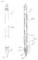
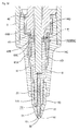
- the ballpoint pen 1 includes a pen tip 20 that has a writing ball 30 and a holder 21 that holds the writing ball 30 using a narrowed portion 23 (see Fig.3 ) that has a narrowed tip end, an ink supply portion 40 that supplies ink to the holder 21 of the pen tip 20, a shaft tube 10 that stores the ink supply portion 40 therein, and an outer member 50 that covers an outer circumference of the holder 21.
- the shaft tube 10 includes a shaft body 11 having an ink storage portion 13 and a front shaft portion 12 provided at a tip end of the shaft body 11, and the ink supply portion 40 and a joint 14 that connects the ink supply portion 40 and the pen tip 20 are included on a tip end side of the shaft body 11.
- Ink (not illustrated) is filled in the ink storage portion 13.
- the ink supply portion 40 has an approximately tubular collector 41 in which a plurality of fins are formed on an outer circumference thereof and a tip holding portion 42 formed by narrowing a tip end of the collector 41.
- a rear end portion of the collector 41 is in contact with the ink storage portion 13, and the tip holding portion 42 is fitted into the front shaft portion 12.
- a rear end portion of the joint 14 is fitted into the tip holding portion 42.
- a rod-shaped collector core 43 made from polyester fiber passes in an axial direction of the collector 41.
- a rear end of the collector core 43 protrudes into the ink storage portion 13, and a tip end portion of the collector core 43 protrudes further toward the tip end than the tip holding portion 42 and is inserted inside from the rear end portion of the joint 14.
- the pen tip 20 includes the cylindrical holder 21 and the writing ball 30 held in the holder 21.
- An approximately conical tapered portion 22 which is narrowed toward the tip end is formed on a tip end side of the holder 21, and the narrowed portion 23 deformed by pressing an opening edge of the tapered portion 22 toward the inner side to reduce the diameter of the opening edge is formed on the tip end side.
- a tip end portion of the writing ball 30 held in a ball house 24 (see Fig.3 ) that is formed in an inner side of the tapered portion 22 is exposed from a tip edge of the narrowed portion 23.
- the holder 21 can be formed by processing a pipe material made from metal such as stainless steel and a resin such as polyacetal.
- a rod-shaped central core 25 that protrudes from the rear end portion of the holder 21 is inserted into the holder 21.
- the central core 25 is formed from polyester fiber similarly to the collector core 43 and has a rear end that is fitted into the tip end portion of the collector core 43 and a tip end that reaches the rear end of the writing ball 30.
- the central core 25 absorbs ink entering into the collector core 43 to supply ink to the ball house 24.
- the pen tip 20 is held in the joint 14 in a state where a portion of the pen tip 20 corresponding to approximately 2/3 of the entire length from the rear end side is fitted into the tip end portion of the joint 14.
- collector core 43 and the central core 25 are formed by appropriately selecting the porosity and the surface shape of polyester fiber according to a property such as viscosity of ink used.
- the outer member 50 is an approximately conical tube made from a synthetic resin, and as illustrated in Fig.2 , has a tapered portion 54 that is tapered toward the tip end.
- a round-chamfered outer member tip end portion 51 is formed in a tip end portion of the tapered portion 54. Further, the outer member tip end portion 51 may be taper-chamfered so as to have an inclined surface rather than being round-chamfered.
- the outer member 50 has a rear insertion hole 52 formed on the rear side and a front insertion hole 53 that passes from the rear insertion hole 52 to the tip end side and has a smaller diameter than the rear insertion hole 52.
- the tip end portion of the joint 14 is inserted into the rear insertion hole 52, and the holder 21 of the pen tip 20 protruding from the joint 14 is inserted into the front insertion hole 53.
- the outer member 50 is configured to be fixed to the tip end portion of the joint 14 to cover the joint 14 and the holder 21 exposed from the front shaft portion 12 in a state where the holder 21 is inserted into the front insertion hole 53 and the tip end portion of the joint 14 is inserted into the rear insertion hole 52.
- a portion of the outer member tip end portion 51 closest to the tip end side is positioned at a position that slightly exceeds a boundary line between the tapered portion 22 and the narrowed portion 23 of the holder 21. That is, the outer member 50 covers a portion extending up to the narrowed portion 23 of the holder 21.
- a portion of the outer member 50 corresponding to approximately 2/3 of the entire length close to the tip end, the narrowed portion 23 of the holder 21, and a portion of the writing ball 30 are exposed from the tip end of the front insertion hole 12. Further, the outer member may be fixed to the joint 14 and may be integrated with the front shaft portion 12.
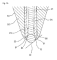
- the outer member tip end portion 51 of the outer member 50 is formed in such a shape as to swell from the outer surface of the narrowed portion 23 so that the narrowed portion 23 is positioned on the inner side (closer to the writing ball 30) than a tangent L that touches both the outer member tip end portion 51 and the writing ball 30. That is, the outer member tip end portion 51 is formed such that the narrowed portion 23 does not protrude toward the front side further than the tangent L.
- relatively low-viscosity ink capable of diffusing between the contact portion of the writing ball 30 and the writing surface and the contact portion of the outer member tip end portion 51 and the writing surface in a state where the writing ball 30 and the outer member tip end portion 51 are in contact with the writing surface simultaneously is used.
- the use of such ink prevents blurring even when bold lines are drawn.
- the ink leaks into the space portion with rotation of the writing ball 30 and it is possible to draw a line having the width w2 wider than the width w1 with the ink diffusing between the contact portion of the writing ball 30 and the writing surface and the contact portion of the outer member tip end portion 51 and the writing surface.
- a contacting state of the tip end portion on the sheet surface may be changed as well as the angle of the contact portion in relation to the writing surface.
- the ballpoint pen 1 can change the width of drawn lines remarkably just by changing the angle in relation to the writing surface during writing and the contacting state of the writing portion on the sheet surface and gradually narrow drawn lines with strokes such as "stop,” "hook,” and "fade.” That is, when a user draws narrow lines, the user may put the shaft tube 10 in a close-to-vertical state (standing state) as illustrated in Fig.4A . When a user draws bold lines, the user may put the shaft tube 10 in a more inclined state (lying state) than when the user draws narrow lines as illustrated in Fig.4B .
- the shape (the amount of protrusion toward the front side or the lateral side) of the outer member tip end portion 51 of the outer member 50 it is possible to equalize the line width when the writing ball 30 and the outer member tip end portion 51 make contact with the writing surface simultaneously, even when the writing ball 30 has a different ball diameter.
- Figs.7A and 7B to Fig.13 illustrate the second embodiment of the present invention.
- the same constituent components as those of the first embodiment will be denoted by the same reference numerals as those used in the first embodiment.
- the same goes for the third to fifth embodiments.
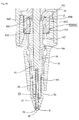
- a ballpoint pen 1 includes a pen tip 20 that has a writing ball 30 and a holder 21 that holds the writing ball 30 using a narrowed portion 23 (see Fig.9 ) that has a narrowed tip end, an ink supply portion 40 that supplies ink to the holder 21 of the pen tip 20, a shaft tube 10 that stores the ink supply portion 40 therein, and an outer 50 that covers an outer circumference of the holder 21.
- the ballpoint pen 1 includes a cap 60 for protecting the tip end portion of the pen tip 20.
- the cap 60 covers a portion of the shaft tube 10 corresponding to approximately 1/3 of the entire length close to the tip end side.
- the cap 60 includes a tube 61 made from a synthetic resin and a lid member 62 that is fitted from the tip end side of the tube 61, and a pen tip receiving portion 63 is provided in the cap 60.
- a rear end portion 61A of the tube 61 is locked at an end portion 15 (see Figs.8A and 8B ) formed by narrowing the diameter of the shaft body 11 and the tip end portion of the pen tip 20 is positioned in the pen tip receiving portion 63.
- the central core 25 is separated by a very small distance from a bottom surface of a recess portion 43A formed in the tip end surface of the collector core 43.
- a vertical groove 14A in a radial shape in a cross-sectional view, extending in the axial direction is formed in a portion of the joint 14 protruding from the tip holding portion 42.
- the outer member 50 of the present embodiment has an end portion 56 which is formed by narrowing the diameter thereof and which is disposed at substantially the same position as the tip end portion of the front shaft portion 12 or slightly close to the tip end side.
- a chamfered portion 55 that is tapered toward the tip end is formed in the tip end portion of the tapered portion 54 of the outer member 50, and a round-chamfered outer member tip end portion 51 that makes contact with the writing surface simultaneously with the writing ball 30 is formed in a tip end portion of the chamfered portion 55.
- the outer member tip end portion 51 may be taper-chamfered so as to have an inclined surface rather than being round-chamfered.
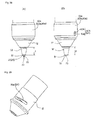
- the ballpoint pen 1 according to the second embodiment provides the same advantageous effects as the first embodiment. That is, when the ballpoint pen 1 is so inclined that an angle of the tapered portion 54 of the outer member 50 in relation to the writing surface is a° as illustrated in Fig.11A , it is possible to allow the writing ball 30 only to make contact with the writing surface as illustrated in Fig.12 to draw a line having the width w1. Moreover, when the ballpoint pen 1 is so inclined that the angle of the tapered portion 54 of the outer member 50 in relation to the writing surface is b° smaller than a° as illustrated in Fig.11B , it is possible to allow the writing ball 30 and the outer member tip end portion 51 to make contact with the writing surface simultaneously as illustrated in Fig. 13 to draw a line having the width w2 wider than the width w1 (see Figs.11A and 11B to Fig.13 ).
- Figs.14A and 14B to Fig.16 illustrate the third embodiment of the present invention.
- the same constituent components as those of the second embodiment will be denoted by the same reference numerals as those used in the second embodiment (The same goes for the fourth and fifth embodiments).
- redundant description of portions overlapping those of the first and second embodiments will not be provided, and features of the present embodiment will be described.
- the ballpoint pen 1 As illustrated in Figs.14A and 14B , the ballpoint pen 1 according to the third embodiment has an ink refill 70 to which the pen tip 20 is fixed and which is stored in the shaft tube 10 and a cap 60 for protecting the tip end portion of the pen tip 20.
- the pen tip 20 of the present embodiment has a small-diameter portion 21A formed in a tip end portion of the cylindrical holder 21 and a tapered portion 22 and a narrowed portion 23 which are provided in the tip end of the small-diameter portion 21A and in which the writing ball 30 is held.
- the holder 21 is hollow.
- the cap 60 covers a portion close to the tip end side of the shaft tube 10 corresponding to an approximately 1/4 of the entire length.
- the cap 60 includes a tube 61 made from a synthetic resin and a lid member 62 that is fitted from the tip end side of the tube 61, and a pen tip receiving portion 63 is provided in the cap 60.
- a rear end portion 61A of the tube 61 is locked at a step 15 formed by narrowing the diameter of the shaft body 11 and the tip end portion of the pen tip 20 is positioned in the pen tip receiving portion 63.
- the ink refill 70 includes an ink storage tube 71 in which ink is filled, a joint 72 fixed to the tip end of the ink storage tube 71, and a pen tip 20 fixed to the joint 72.
- the ink storage tube 71 is a polypropylene tube in which ink (not illustrated) and an ink following body for preventing ink leakage are filled.
- the joint 72 is a tubular member which has an opening that extends in a front-to-rear direction and of which the rear portion is press-fitted into the ink storage tube 71.
- the pen tip 20 is press-fitted into the front opening of the joint 72 exposed from the ink storage tube 71, and the ink in the ink storage tube 71 is supplied to the pen tip 20 from the rear opening.
- the ink refill 70 has the ink storage tube 71 stored in the shaft body 11, and the joint 71 and the pen tip 20 exposed from the joint 71 are covered by the front shaft portion 12.
- the outer member 50 has an insertion opening 57 in which the small-diameter portion 21A of the holder 21 is inserted from the rear side.
- the outer member 50 is fixed to the tip end portion of the holder 21 to cover the holder 21 in a state where the small-diameter portion 21 A of the holder 21 is inserted in the insertion opening 57. Further, when the ink refill 70 is stored in the shaft tube 10, the outer member 50 is exposed from the tip end of the front shaft portion 12 as illustrated in Fig.14B .
- the ballpoint pen 1 according to the third embodiment provides the same advantageous effects as the first embodiment. Further, in the present embodiment, unlike the first and second embodiments, when ink in the ink refill 70 is used up and it is not possible to write, a user can replace the ink refill 70 and write again.
- Figs.17A and 17B and Fig.18 illustrate the fourth embodiment of the present invention.
- redundant description of portions overlapping those of the first to third embodiments will not be provided, and features of the present embodiment will be described.
- the ballpoint pen 1 As illustrated in Figs.17A and 17B , the ballpoint pen 1 according to the fourth embodiment has an ink refill 70 to which the pen tip 20 is fixed and which is stored in the shaft tube 10. Although not illustrated in the drawings, the ballpoint pen 1 may include a cap for protecting the tip end portion of the pen tip 20.
- an approximately conical outer member 50 formed so as to be tapered toward the tip end is attached to the tip end portion of the shaft tube 10.
- An insertion hole 57 that passes from the rear side to the tip end side is formed in the outer member 50, and a screw portion 57A is formed on an inner circumferential surface on the rear side of the insertion hole 57 as illustrated in Figs.17B and Fig. 18 .
- a screw portion 11 A formed on the outer circumference on the tip end side of the shaft body 11 engages with the screw portion 57A to fix the outer member 50 and cover the joint 71 and the pen tip 20 exposed from the joint 71. That is, in the present embodiment, the outer member 50 also serves as a front shaft portion.
- FIGs.19A and 19B and Fig.20 illustrate the fifth embodiment of the present invention.
- a ballpoint pen 1 according to the present embodiment has a writing ball 30 having a larger diameter than the writing ball 30 of the fourth embodiment.
- the other configuration is the same as that of the fourth embodiment except that, since the diameter of the tip end portion of the pen tip 20 is larger than that of the fourth embodiment, the taper angle of the outer member 50 is gentle and a tapered portion having a different angle is provided in the tip end portion of the outer member 50.
- Fig 21 to 26 illustrate the sixth embodiment of the present invention.
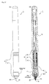
- the ballpoint pen 1 includes a pen tip 20 that has a writing ball 30 and a holder 21 which is a first writing portion that holds the writing ball 30 using a narrowed portion 23 (see Figs.24 and 25 ) that has a narrowed tip end, an ink supply portion 40 that supplies ink to the holder 21 of the pen tip 20, a shaft tube 10 that stores the ink supply portion 40 therein, an outer member 50 which is a second writing portion that covers an outer circumference of the holder 21, and a displacement means 60a for changing a relative position in the axial direction of the outer member 50 and the holder 21.
- a cap which can be detachably attached to the tip end and the rear end of the shaft tube 10 is also provided.
- the shaft tube 10 includes a shaft body 11 having an ink storage portion 13 and a front shaft portion 12 provided at a tip end of the shaft body 11, and the ink supply portion 40 and a joint 14 that connects the ink supply portion 40 and the pen tip 20 are included on a tip end side of the shaft body 11.
- Ink (not illustrated) is filled in the ink storage portion 13.
- the ink supply portion 40 has an approximately tubular collector 41 in which a plurality of fins is formed on an outer circumference thereof and a tip holding portion 42 formed by narrowing a tip end of the collector 41. A rear end portion of the collector 41 is in contact with the ink storage portion 13, and the tip holding portion 42 is fitted into the front shaft portion 12.
- a rear end portion of the joint 14 is fitted into the tip holding portion 42.
- a rod-shaped collector core 43 made from polyester fiber passes in an axial direction of the collector 41.
- a rear end of the collector core 43 protrudes into the ink storage portion 13, and a tip end portion of the collector core 43 protrudes further toward the tip end than the tip holding portion 42 and is fitted into the joint 14 from the rear end portion of the joint 14.
- the joint 14 is so formed as to be slidable through the tip holding portion 42 in the axial direction integrally with the collector core 43.
- the pen tip 20 includes the cylindrical holder 21 and the writing ball 30 held in the holder 21.
- An approximately conical tapered portion 22 which is narrowed toward the tip end is formed on a tip end side of the holder 21, and the narrowed portion 23 (see Fig.24 ) deformed by pressing a small opening of the tapered portion 22 toward the inner side to reduce the diameter of the opening is formed on the tip end side.
- a tip end portion of the writing ball 30 held in a ball house 24 that is formed in an inner side of the tapered portion 22 is exposed from a tip edge of the narrowed portion 23.
- the holder 21 can be formed by processing a pipe material made from metal such as stainless steel and a resin such as polyacetal.
- a rod-shaped central core 25 that protrudes from the rear end portion of the holder 21 is inserted into the holder 21.
- the central core 25 is formed from polyester fiber similarly to the collector core 43 and has a rear end that is fitted into the tip end portion of the collector core 43 and a tip end that reaches the rear end of the writing ball 30.
- the central core 25 absorbs ink entering into the collector core 43 to supply ink to the ball house 24.
- the pen tip 20 is held in the joint 14 in a state where a portion of the pen tip 20 corresponding to approximately 2/3 of the entire length from the rear end side is fitted into the tip end portion 14A of the joint 14.
- the collector core 43 and the central core 25 are formed by appropriately selecting the porosity and the surface shape of polyester fiber according to a property such as viscosity of ink used.
- an ink refill formed by press-fitting the pen tip 20 into the tip end of an ink storage tube that stores ink and ink core may be provided in the shaft tube 10.
- the outer member 50 is an approximately conical tube made from a synthetic resin, and as illustrated in Fig.22 , has a tapered portion 54 that is tapered toward the tip end.
- a round-chamfered outer member tip end portion 51 is formed in a tip end portion of the tapered portion 54. Further, the outer member tip end portion 51 may be taper-chamfered so as to have an inclined surface rather than being round-chamfered.
- the outer member 50 has a rear insertion hole 52 formed on the rear side and a front insertion hole 53 that passes from the rear insertion hole 52 to the tip end side and has a smaller diameter than the rear insertion hole 52.
- the tip end portion 14A of the joint 14 is inserted into the rear insertion hole 52, and the holder 21 of the pen tip 20 exposed from the joint 14 is inserted into the front insertion hole 53. Further, the tip end portion 14A of the joint 14 is configured to be slidable through the rear insertion hole 52 in the axial direction, and the holder 21 is configured to be slidable through the front insertion hole 53 in the axial direction.
- the outer member 50 is inserted from the tip end side of the holder 21 and the joint 14 protruding from the tip end of the front shaft portion 12 and is fixed to the front shaft portion 12.
- the holder 21 is inserted into the front insertion hole 53 and the tip end portion 14A of the joint 14 is inserted into the rear insertion hole 52.
- a portion of the outer member tip end portion 51 closest to the tip end side is positioned closer to the rear side than the narrowed portion 23 of the holder 21, and the outer member 50, the tapered portion 22 and the narrowed portion 23 of the holder 21, and the writing ball 30 are exposed from the tip end of the front shaft portion 12.
- a positional relation of the outer member 50 and the holder 21 is referred to as a holder protruding position as a protruding position of the first writing portion.
- the holder protruding position is the initial position of the ballpoint pen 1.
- the displacement means 60a is an elastic member disposed in the tip end of the tip holding portion 42 of the ink supply portion 40.
- the elastic member is an O-shaped ring 61 a made from a silicon resin.
- the O-shaped ring 61 a is compressed and deformed by receiving load in the axial direction, and a relative position in the axial direction of the outer member 50 and the holder 21 changes with positional movement of the joint 14 and the pen tip 20 held in the joint 14. Specifically, when load is applied from the tip end of the writing ball 30, force acts on the joint 14 toward the rear side, the O-shaped ring 61a is pressed against the flange portion 14B and crushed against the receiving portion 42A. In this way, the joint 14 and the pen tip 20 move toward the rear side in relation to the outer member 50, the front shaft portion 12, and the tip holding portion 42.
- a portion of the outer member tip end portion 51 closest to the tip end is positioned up to a position slightly exceeding the boundary line between the narrowed portion 23 and the tapered portion 22 of the holder 21. Due to this, a portion of the outer member 50 corresponding to approximately 2/3 of the entire length close to the tip end side, the narrowed portion 23 of the holder 21, and a portion of the writing ball 30 are exposed from the tip end of the front shaft portion 12.
- a positional relation of the outer member 50 and the holder 21 is referred to as a holder retracting position as a retracting position of the first writing portion.
- the O-shaped ring 61a is elastically deformed to restore an original shape and the joint 14 and the pen tip 20 move to the holder protruding position to return to the initial state.
- the narrowed portion 23 is positioned on the inner side (close to the writing ball 30) than a tangent L that touches both the outer member tip end portion 51 and the writing ball 30. That is, the outer member tip end portion 51 is formed in such a shape as to swell from the outer surface of the narrowed portion 23 so that the outer member tip end portion 51, the writing ball 30, and the narrowed portion 23 are in the above-described positional relation in the holder retracting position.
- relatively low-viscosity ink capable of diffusing between the contact portion of the writing ball 30 and the writing surface and the contact portion of the outer member tip end portion 51 and the writing surface in a state where the writing ball 30 and the outer member tip end portion 51 are in contact with the writing surface simultaneously is used.
- the use of such ink prevents blurring even when bold lines are drawn.
- the length from the tip end of the outer member tip end portion 51 to the tip end of the writing ball 30 is "a.”
- a user writes lines in this state, it is possible to draw a line having the width w1 with the ink adhering to the surface of the writing ball 30 as illustrated in Fig.25 .
- ink adhering to the surface of the writing ball 30 diffuses into the writing surface according to capillary phenomenon and adheres to the outer member tip end portion 51, and ink remains in a space portion surrounded by the writing ball 30, the writing surface, the outer member tip end portion 51, and the narrowed portion 23 as illustrated in Fig.26 .
- ink leaks into the space portion with rotation of the writing ball 30 and it is possible to draw a line having the width w2 wider than the width w1 with the ink diffusing between the contact portion of the writing ball 30 and the writing surface and the contact portion of the outer member tip end portion 51 and the writing surface according to capillary phenomenon.
- the positional relation between the writing ball 30 and the narrowed portion 23 is maintained, it is possible to maintain the amount of ink leaking with rotation of the writing ball 30 to be constant and to prevent ink leakage.
- the ballpoint pen 1 according to the sixth embodiment can change the width of drawn lines just by changing writing load during writing. That is, the writing load may be decreased so that the pen tip 20 does not retract when a user draws narrow lines, and the writing load may be increased so that the pen tip 20 retracts when a user draws bold lines. Further, in the present embodiment, since it is easy to change the width and the thickness of lines in the middle of writing by changing the width of drawn lines according to writing load, the ballpoint pen is ideally used for drawing and ballpoint pen-based calligraphy.
- the shape (the amount of protrusion toward the front side or the lateral side) of the outer member tip end portion 51 of the outer member 50 it is possible to equalize the line width when the writing ball 30 and the outer member tip end portion 51 make contact with the writing surface simultaneously, even when the writing ball 30 has a different ball diameter.
- the elastic member is not limited to the O-shaped ring 61 a but a spring may be used.
- the joint 14 and the pen tip 20 are so formed as to move integrally, the pen tip 20 only may move.
- Figs.27A and 27B to Fig.31 illustrate the seventh embodiment of the present invention. Further, Figs.25 and 26 of the sixth embodiment are also applicable to the seventh embodiment. Moreover, in the seventh embodiment, the same constituent components as those of the sixth embodiment will be denoted by the same reference numerals as those used in the sixth embodiment. Hereinafter, redundant description of portions overlapping those of the sixth embodiment will not be provided, and features of the present embodiment will be described. The same goes for the eighth to fourteenth embodiments.
- the outer member 50 is so formed as to be movable in the axial direction in relation to the pen tip 20 and includes a rotary feeding mechanism 62a that can move the outer member 50 between a holder protruding position and a holder retracting position as the displacement means 60a.
- the outer member 50 of the present embodiment has a rear-side portion received in a shaft tip portion 12 and is so supported as to be slidable in an axial direction between the shaft tip portion 12 and the joint 14 that holds the pen tip 20.
- the rotary feeding mechanism 62a includes a tubular rotation operating portion 63a positioned at the tip end side of the shaft body 11 so as to cover the outer circumference of the shaft tip portion 12 and a feeding mechanism portion 64 illustrated in Figs.29 to 31 disposed between the shaft tip portion 12 and the outer member 50.
- the rotation operating portion 63a moves the outer member 50 by being rotated in the circumferential direction.
- the feeding mechanism portion 64 moves the position of the outer member 50 back and forth with rotation of the rotation operating portion 63a.
- the feeding mechanism portion 64 includes a cam hole 15a (see Fig.29 ) formed on a side surface of the shaft tip portion 12, a pin 55a (see Figs.30 and 31 ) provided on the outer member 50, and a long hole 63A (see Fig.30 ) formed on a side surface of the rotation operating portion 63a.
- the cam hole 15a is formed obliquely in a direction crossing the axial direction of the shaft tip portion 12 so that the distance from the tip end of the shaft tip portion 12 at one end portion is different from the distance from the tip end of the shaft tip portion 12 at the other end portion.
- the long hole 63A is so formed that the length direction extends in the axial direction of the rotation operating portion 63a as illustrated in Fig.30 .
- the pin 55a protrudes in the direction vertical to the shaft from the rear side surface of the outer member 50. Further, as illustrated in Fig.31 , the pin 55a passes through the cam hole 15a and engages with the long hole 63A illustrated in Fig.30 . Further, when the rotation operating portion 63a is rotated around the axial direction, the pin 55a moves along the cam hole 15a and the outer member 50 moves back and forth.
- Fig.28A illustrates a state where the positional relation between the outer member 50 and the holder 21 is at the holder protruding position. In this state, the length from the tip end of the front shaft portion 12 to the outer member tip end portion 51 is "c."
- the writing ball 30 and the outer member tip end portion 51 will not make contact with the writing surface simultaneously. Thus, it is possible to draw a line having the width w1 illustrated in Fig.25 with the ink adhering to the surface of the writing ball 30.
- a state where narrow lines can be drawn and a state where bold lines can be drawn can be selected in advance, it is not necessary to change writing load in the middle of writing and users can write lines with constant writing load. Moreover, the width of lines may not be changed unintentionally with a change in the writing load during writing. In particular, in the holder retracting position, by maintaining the angle of the writing tip to be constant, it is possible to draw bold lines stably without changing the writing load.
- the pin 55a is visible from the long hole 63A of the rotation operating portion 63a, it is possible to immediately recognize whether the writing tip state (the positional relation between the outer member 50 and the holder 21) is at the holder protruding position or the holder retracting position. That is, when the writing tip state is at the holder protruding position, the pin 55a is positioned on the front side of the long hole 63A. In contrast, when the writing tip state is at the holder retracting position, the pin 55a is positioned on the rear side of the long hole 63A. Thus, it is possible to recognize the writing tip state.
- the means for displacing the outer member 50 is not limited to the rotary feeding mechanism 62a, but for example, a knob may be slid to allow the outer member 50 to protrude and retract.
- a male screw and a female screw may be formed on the outer circumference of the outer member 50 and the inner circumference of the front shaft portion 12 and the outer member 50 may be moved in the axial direction by rotating the outer member 50.
- a feeding mechanism may be used as the means for moving the joint 14 and the pen tip 20.
- Fig.32 illustrates the eighth embodiment of the present invention.
- the elastic member is the O-shaped ring 61 a in the sixth embodiment, and is an elastic joint 65 in the present embodiment.
- a rear end portion 14C of the joint 14 is separated from the tip end portion of the tip holding portion 42 of the ink supply portion 40, and the elastic joint 65 is interposed as a means for connecting the joint 14 and the tip holding portion 42.
- the elastic joint 65 includes a front tube portion 65A and a rear tube portion 65B having a slightly larger diameter than the front tube portion 65A, the rear end portion of the joint 14 is fitted into the front tube portion 65A, and the front end portion of the tip holding portion 42 is fitted into the rear tube portion 65B.
- a flange-shaped inner protrusion 65C that protrudes toward the center and makes contact with a rear end surface 14D of the joint 14 is formed inside the elastic joint 65.
- a gap P is formed between a rear end of the inner protrusion 65C and a tip end surface 42B of the tip holding portion 42. That is, the inner protrusion 65C is sandwiched between the tip end surface 42B of the tip holding portion 42 and the rear end surface 14D of the joint 14 and makes contact with the rear end surface 14D of the joint 14.
- the inner protrusion 65C pressed toward the rear side by the joint 14 bends toward the rear side, and the writing tip can move toward the rear side.
- the gap P narrows. That is, the gap P is a space portion for allowing deformation of the inner protrusion 65C.
- the elastic joint 65 as the elastic member may be formed from a material that allows the inner protrusion 65C to be bent with writing load and may be preferably formed from rubber, a rubber-like elastic material such as elastomer, and a relatively soft resin material such as polypropylene.
- the first writing portion When the elastic member can be deformed with very small load, the first writing portion can be put into the retracting position and users can draw bold lines constantly without experiencing discomfort during writing. Moreover, when the writing portion becomes distant from the writing surface for example, when a user creates strokes such as "hook” and "fade” and the writing load decreases, the first writing portion continuously moves from the retracting position to the protruding position, whereby a bold line changes to a narrow line continuously and smoothly. Moreover, by changing a volume associated with deformation of the shape of the elastic member to allow an ink passage to be pressed by the writing load, it is possible to provide satisfactory ink flowability during initial writing.
- Fig.33 illustrates the ninth embodiment of the present invention.
- the shape of the elastic joint 65 as the elastic member of the eighth embodiment is changed.
- the rear end portion 14C of the joint 14 is inserted into the tip end portion of the tip holding portion 42 of the ink supply portion 40, and the elastic joint 65 is interposed between the rear end portion and the tip end portion. That is, the elastic joint 65 includes a front tube portion 65A and a rear tube portion 65B having a slightly smaller diameter than the front tube portion 65A.
- the rear tube portion 65B is fitted into a recess portion 42C formed in the tip end portion of the tip holding portion 42, and the front tube portion 65A is sandwiched between the tip end surface 42B of the tip holding portion 42 and a step 12A formed on the inner circumference on the rear side of the front shaft portion 12.
- a flange-shaped inner protrusion 65C that protrudes toward the center and makes contact with a rear end surface 14D of the joint 14 is formed on the rear end portion of the rear tube portion 65B. Further, a gap P is formed between the rear end surface of the elastic joint 65 (the rear end surface of the inner protrusion 65C) and a recess bottom 42D of the recess portion 42C of the tip holding portion 42.
- the inner protrusion 65C pressed toward the rear side by the joint 14 bends toward the rear side, and the writing tip can move toward the rear side.
- the joint 14 is pushed back to return to the original position by the restoring force of the inner protrusion 65C.
- Fig.34 illustrates the tenth embodiment of the present invention.
- an elastic joint 65 is provided as the elastic member.
- the rear end portion 14C of the joint 14 is inserted into a recess portion 42C formed in the tip end portion of the tip holding portion 42 of the ink supply portion 40, and the elastic joint 65 covers the tip end portion of the tip holding portion 42 and the rear end portion 14C of the joint 14 protruding from the tip holding portion 42.
- the elastic joint 65 includes a front tube portion 65A and a rear tube portion 65B having a slightly larger diameter than the front tube portion 65A, the rear end portion 14C of the joint 14 is fitted into the front tube portion 65A, and the front end portion of the tip holding portion 42 is fitted into the rear tube portion 65B.
- a tapered portion 65D of which the inner diameter decreases toward the rear end side is provided on the inner circumference of the front tube portion 65A. That is, the front tube portion 65A is so formed that the thickness decreases toward the tip end side. Moreover, the front end portion of the elastic joint 65 (the front end portion of the front tube portion 65A) is in contact with the rear end of the flange portion 14B of the joint 14, and the rear tube portion 65B is sandwiched between the tip end portion of the tip holding portion 42 and the step 12A formed on the inner circumference on the rear end side of the front shaft portion 12.
- Figs.35A and 35B and Figs.36A and 36B illustrate the eleventh embodiment of the present invention.
- the ballpoint pen 1 As illustrated in Figs.35A and 35B , the ballpoint pen 1 according to the eleventh embodiment has an ink refill 70 to which the pen tip 20 is fixed and which is stored in the shaft tube 10.
- the pen tip 20 of the present embodiment has a small-diameter portion 21A formed in a tip end portion of the cylindrical holder 21 and a tapered portion 22 and a narrowed portion 23 which are provided in the tip end of the small-diameter portion 21A and in which the writing ball 30 is held.
- the holder 21 is hollow and is filled with ink during writing.
- the ink refill 70 includes an ink storage tube 71 in which ink is filled, a joint 72 fixed to the tip end of the ink storage tube 71, and a pen tip 20 fixed to the joint 72.
- the ink storage tube 71 is a polypropylene tube in which ink (not illustrated) and an ink following body for preventing ink leakage are filled.
- the joint 72 is a tubular member which has an opening that extends in a front-to-rear direction and of which the rear portion is press-fitted into the ink storage tube 71.
- the pen tip 20 is press-fitted into the front opening of the joint 72 exposed from the ink storage tube 71, and the ink in the ink storage tube 71 is supplied to the pen tip 20 from the rear opening.
- the ink refill 70 has the ink storage tube 71 stored in the shaft body 11, and the joint 71 and the pen tip 20 exposed from the joint 71 are covered by the outer member 50.
- the outer member 50 is formed in an approximately conical form so as to be tapered toward the tip end.
- an insertion hole 57 that passes from the rear side to the tip end side is formed in the outer member 50.
- a screw portion 57A is formed on an inner circumferential surface on the rear side of the insertion hole 57.
- a screw portion 11A formed on the outer circumference on the tip end side of the shaft body 11 engages with the screw portion 57A whereby the outer member 50 is fixed. That is, in the present embodiment, the outer member 50 also serves as a front shaft portion.
- a spring 66 as an elastic member is disposed on the rear side of the ink refill 70.
- the spring 66 is a compression coil spring that biases the ink storage tube 71 toward the tip end side, and in a normal state, the ink refill 70 is at the holder protruding position illustrated in Fig.36A . Further, when writing load is applied to the writing tip, the spring 66 is compressed by the rear end portion of the ink storage tube 71 and the entire ink refill 70 moves toward the rear side and is positioned at the holder retracting position illustrated in Fig.36B .
- the elastic member is not limited to the spring 66 but a member which is restored according to elastic action may be used.
- an elastic body formed from rubber or a rubber-like elastic material such as elastomer may be used.
- Figs.37A and 37B and Fig.38 illustrate the twelfth embodiment of the present invention.
- a ballpoint pen 1 according to the present embodiment has a writing ball 30 having a larger diameter than the writing ball 30 of the eleventh embodiment.
- the other configuration is the same as that of the eleventh embodiment except that, since the diameter of the tip end portion of the pen tip 20 is larger than that of the eleventh embodiment, the taper angle of the outer member 50 is gentle, and a tapered portion having a different angle is provided in the tip end portion of the outer member 50.
- the shape of the pen tip 20 is not particularly limited as long as lines can be written with the pen tip.
- Figs.39A and 39B to Fig.41 illustrate the thirteenth embodiment of the present invention.
- a displacement means 60a is formed in the outer member 50.
- the outer member 50 of the present embodiment includes a compression portion 56a in which a plurality of slits 56A is formed in a central portion between the tip end portion and the rear end portion.
- the slits 56A are so formed as to pass through the cylindrical outer member 50 from the side surface and three stages of slits 56A are positioned in a staggered manner. Due to the slits 56A, when pressure is applied in the axial direction of the outer member 50, the compression portion 56a is deformed and the entire length of the outer member 50 decreases.
- the tip end portion of the pen tip 20 does not protrude from the outer member tip end portion 51.
- the outer member 50 may be attached to the front shaft portion 12 and may be attached to the tip end portion of the shaft body 11 (that is, the outer member 50 may also serve as the front shaft portion 12). The outer member 50 may be attached directly to the pen tip.
- the writing tip end portion 51 when the outer member tip end portion 51 is pressed against the writing surface during writing, as illustrated in Fig.41 , the slits 56A of the compression portion 56a are compressed, the length of the outer member 50 decreases, and the tip end portion (the writing ball 30 and the narrowed portion 23) of the pen tip 20 is exposed. In this case, the writing tip is at the position as illustrated in Fig.26 of the sixth embodiment.
- the length of the outer member 50 restores the original length by the restoring force of the compression portion 56a, and the tip end portion of the pen tip 20 is retracted toward the inside of the outer member 50.
- the elastic member in the shaft tube 10 since it is not necessary to provide the elastic member in the shaft tube 10, it is easy to manufacture the ballpoint pen. Moreover, when the outer member 50 is formed to be fixed by being screwed into the shaft body 11, it is possible to replace the outer member 50 easily even when the compression portion 56a is broken.
- Figs.42A and 42B illustrate the fourteenth embodiment of the present invention.
- a step portion 58 is formed on the surface of the outer member 50 to prevent ink contamination of the rear side.
- the step portion 58 is formed by narrowing a portion of the outer member 50 close to the tip end of the tapered portion 54. Due to the step portion 58, it is possible to prevent ink adhering to a tapered portion 54B closer to the tip end than the step portion 58 from diffusing toward a tapered portion 54A closer to the rear side than the step portion 58 and to prevent a portion of the outer member 50 close to the tip end from being contaminated.
- the step portion 58 of the present embodiment can be also applied to the sixth to thirteenth embodiments.
- Fig.43 illustrates handwritings written by a ballpoint pen, a felt-tip pen, a fountain pen, and the ballpoint pen 1 according to the present invention.
- the ballpoint pen 1 can create strokes ⁇ "stop,” ⁇ "hook,” and ⁇ "fade” which are the ends of strokes more easily and with higher quality than the ballpoint pen, the felt-tip pen, and the fountain pen.
- the writing load applied to the writing tip at the ends of strokes can be smoothly changed with the elastic member in the shaft tube as compared to the conventional writing instruments, it is possible to create brush-like strokes "stop,” "hook,” and "fade.”
- the present invention can be used for writing instruments such as a ballpoint pen.
Landscapes
- Pens And Brushes (AREA)
Abstract
Description
- The present invention relates to a ballpoint pen capable of changing the width of drawn lines.
- Conventionally, as a technique related to a ballpoint pen capable of writing drawn lines having different widths using one writing shaft, as disclosed in
Patent Literature 1, a technique of controlling the amount of ink leakage using a pressurizing mechanism provided in a rear end portion in a shaft tube to change a width and a thickness of a drawn line is known. - Moreover, as disclosed in Patent Literature 2, a technique of changing the width and thickness of drawn lines using a ballpoint pen in which pen tips having different ball diameters are attached to both ends of a writing shaft is also known.
- Moreover, conventionally, as a technique related to a ballpoint pen capable of writing drawn lines having different widths using one writing tip, as disclosed in Patent Literature 3, a technique of providing a spring inside a holder so that a writing ball is always pressed toward the writing tip by the resilience of the spring and allowing lines of different widths to be drawn according to a writing load is known. Moreover, a writing instrument capable of moving a marking surface portion back and forth and writing a plurality of narrow and bold lines is also disclosed.
-
- Patent Literature 1:
JP 2006-289833 A - Patent Literature 2:
JP 08-6551 U - Patent Literature 3:
JP 08-187987 A - Patent Literature 4:
JP 2007-502729 A - In the invention disclosed in
Patent Literature 1, since a pressurizing mechanism is provided in a writing instrument, the writing instrument has a complex structure. Thus, it is difficult to adjust the pressing force of the pressurizing mechanism during writing, and a redundant amount of ink may leak. - Moreover, in the invention disclosed in Patent Literature 2, since only two types of pen tips are used in addition to the inconvenience to invert the writing shaft, it is possible to draw bold and narrow lines only. However, it is not possible to adjust the width of drawn lines.
- Therefore, an object of the present invention is to provide a ballpoint pen which has a simple structure and which can write drawn lines of different widths using one writing tip without requiring special operations during writing and freely change the width of drawn lines.
- Moreover, in the invention disclosed in Patent Literature 3, the gap between the writing ball and a narrowed portion of the holder is changed whereby the amount of ink leakage changes and the width and thickness of drawn lines change. The range where the writing ball can move within the holder is limited. Since a large amount of ink leaks if the movable distance is increased, it is difficult to draw lines satisfactorily. Due to this, there is a limit even when the line width is increased.
- In the invention disclosed in Patent Literature 4, since lines are drawn using the surface of a component, it is difficult to provide smooth writing performance. Moreover, when a shiftable pin is replaced with a pen tip having a writing ball in order to provide smooth writing performance, ink leaking from the gap of the pen tip does not reach the marking surface portion. Thus, it is difficult to write narrow and bold lines having a plurality of widths.
- Thus, another object of the present invention is to provide a ballpoint pen which can write drawn lines of different widths using one writing ball and a writing portion made up of two components while maintaining an optimal positional relation between a writing ball and a holder, freely change the width of drawn lines, and easily write characteristic drawn lines with strokes such as "stop," "hook," and "fade."
- In order to solve the problems, the present invention has the following configurations.
- A first aspect of the present invention is a ballpoint pen configured to be capable of writing drawn lines of different widths using one writing tip.
- A second aspect of the present invention includes the following configuration in addition to the configuration of the first aspect of the invention. That is, the ballpoint pen includes: a writing ball; a holder that holds the writing ball by a narrowed portion with a narrowed tip end; an ink supply portion that supplies ink to the holder; a shaft tube that stores the ink supply portion therein; and an outer member that covers an outer circumference of the holder, wherein a part of the holder holding the writing ball and a part of the outer member are exposed from a tip end portion of the shaft tube, and the writing ball and an outer member tip end portion form a writing portion.
- The shaft tube may be configured to capably store ink therein directly and may be configured to store a refill in which ink is filled. The ink supply portion may be configured to supply ink stored in the shaft tube to the holder with the aid of an intermediate member such as a collector and may be configured to supply ink stored in an ink storage tube such as a refill which is separated from the shaft tube to the holder.
- The holder has a tip end which is exposed from the tip end portion (front shaft portion) of the shaft tube and has a rear end which is positioned inside the shaft tube and communicates with the ink supply portion. A ball house is formed in the tip end of the holder, and the writing ball is held in the ball house. The holder can be formed by cutting or injection-molding a metal material such as stainless steel or a resin material such as polyacetal.
- The outer member is a tubular member that covers at least a portion of the holder exposed from the shaft tube and is preferably formed from a synthetic resin. The holder is covered with the outer member and only the narrowed portion is exposed from the outer member. Moreover, the outer member tip end portion is a tip end portion of the outer member and is configured to capably make contact with the writing surface substantially simultaneously with the writing ball. That is, the outer member tip end portion swells further toward the outer side (the outer circumference) than the narrowed portion, and the narrowed portion is at the same position as the tangent that touches both the writing ball and the outer member tip end portion or does not protrude toward the tip end.
- In the ballpoint pen according to this aspect, when a user writes lines in a state where the shaft tube is approximately vertical to the writing surface (standing state) or in a state where the writing portion does not get into the writing surface, only the writing ball makes contact with the writing surface, and it is possible to draw lines having a predetermined width with the ink adhering to the periphery of the writing ball. On the other hand, when a user writes lines in a state where the shaft tube is inclined to some extent in relation to the writing surface (lying state) or in a state where the writing portion gets into the writing surface, the writing ball and the outer member tip end portion make contact with the writing surface simultaneously, and the ink adhering to the periphery of the writing ball and the ink leaking from the inside of the holder with rotation of the writing ball diffuse between the contact portion of the writing ball and the writing surface and the contact portion of the outer member tip end portion and the writing surface according to capillary phenomenon. Due to this, it is possible to draw lines having a larger width than when the shaft tube is in the standing state or the writing portion does not get into the writing surface.
- According to this aspect, it is possible to draw lines of different widths by changing the contact state of the writing portion with the writing surface according to an inclination angle of the shaft tube during writing.
- In a third aspect of the present invention, in addition to the configuration of the second aspect of the invention, the outer member covers a part of the holder until it reaches the narrowed portion.
- The outer member tip end portion is configured to cover a portion of the holder reaching the narrowed portion, that is, the outer circumference located closer to the rear side than the narrowed portion.
- According to this aspect, when the writing ball and the outer member make contact with the writing surface simultaneously, ink diffuses into the portion surrounded by the writing surface, the writing ball, and the outer member according to capillary phenomenon. Thus, it is possible to draw bold lines without blurring.
- In a fourth aspect of the present invention, in addition to the configuration of the third aspect of the invention, the ink has such viscosity that the ink can diffuse between a contact portion of the writing ball with a writing surface and a contact portion of the outer member tip end portion with the writing surface, in a state where the writing ball and the outer member tip end portion are in contact with the writing surface simultaneously.
- According to this aspect, when the writing ball and the outer member tip end portion make contact with the writing surface simultaneously, ink diffuses into the portion surrounded by the writing surface, the writing ball, and the outer member tip end portion according to capillary phenomenon. Thus, it is possible to draw bold lines without blurring.
- Furthermore, in order to solve the problems, the present invention includes the following configuration.
- A fifth aspect of the present invention is a ballpoint pen configured to capably write drawn lines of different widths using two writing portions.
- A sixth aspect of the present invention includes the following configuration in addition to the configuration of the fifth aspect of the invention. That is, the ballpoint pen includes: a writing ball; a first writing portion that holds the writing ball by a narrowed portion with a narrowed tip end; an ink supply portion that supplies ink to the first writing portion; a shaft tube that stores the ink supply portion therein; and a second writing portion that covers an outer circumference of the first writing portion, a part of the second writing portion and a part of the first writing portion holding the writing ball being exposed from a tip end portion of the shaft tube; a displacement means that capably changes a relative positional relation in an axial direction between the first writing portion and the second writing portion; wherein the displacement means is formed so that, when a relative position of the first writing portion in relation to the second writing portion is at a retracting position of the first writing portion, the first writing portion and a tip end portion of the second writing portion can make contact with the writing surface simultaneously.
- The shaft tube may be configured to be able to store ink therein directly and may be configured to store a refill in which ink is filled. The ink supply portion may be configured to supply ink stored in the shaft tube to the first writing portion with the aid of an intermediate member such as a collector and may be configured to supply ink stored in an ink storage tube such as an ink refill which is separated from the shaft tube to the first writing portion.
- The first writing portion can be formed by cutting or injection-molding a metal material such as stainless steel or a resin material such as polyacetal. The first writing portion has a tip end which is exposed from the tip end portion (front shaft portion) of the shaft tube and has a rear end which is positioned inside the shaft tube and communicates with the ink supply portion. A ball house is formed in the tip end of the first writing portion, and the writing ball is held in the ball house.
- The second writing portion is a tubular member that covers at least a portion of the first writing portion exposed from the shaft tube and is preferably formed from a synthetic resin. The tip end portion of the second writing portion indicates a tip end portion of the second writing portion and is configured to cover a portion of the first writing portion reaching the narrowed portion, that is, the outer circumference located closer to the rear side than the narrowed portion.
- The displacement means is configured to capably change the relative position of the first writing portion and the second writing portion. This aspect includes two cases: a case where the second writing portion may be so formed as to be movable in relation to the first writing portion so that the second writing portion is displaced by the displacement means; and another case where the first writing portion may be so formed as to be movable in relation to the second writing portion so that the first writing portion is displaced by the displacement means. The displacement means may be an elastic member which can move the first writing portion or the second writing portion in the axial direction by being compressed and deformed when load is applied from the tip end thereof and a mechanism which can move the first writing portion or the second writing portion in the axial direction according to a predetermined operation.
- In this aspect, when the positional relation between the first writing portion and the second writing portion is such that the first writing portion is at the retracting position in relation to the second writing portion, the portion of the first writing portion reaching the narrowed portion is covered with the second writing portion whereby the writing ball and the narrowed portion are exposed from the second writing portion. In this case, the tip end portion of the second writing portion can make contact with the writing surface simultaneously with the writing ball. That is, when the first writing portion is at the retracting position, the narrowed portion is at the same position as the tangent that touches both the writing ball and the tip end portion of the second writing portion or does not protrude further toward the tip end.
- On the other hand, when the positional relation between the first writing portion and the second writing portion is such that the first writing portion is at the protruding position in relation to the second writing portion, a portion of the first writing portion located closer to the rear side than the narrowed portion is covered with the second writing portion, whereby the narrowed portion and the portion located closer to the rear side than the narrowed portion are exposed from the second writing portion. In this case, the tip end portion of the second writing portion does not make contact with the writing surface simultaneously with the writing ball. That is, when the first writing portion is at the protruding position, the tip end portion of the second writing portion does not protrude closer to the tip end than the tangent that touches both the writing ball and the narrowed portion.
- In the ballpoint pen of this aspect, when the relative position of the first writing portion and the second writing portion is at the protruding position of the first writing portion, only the writing ball makes contact with the writing surface, and it is possible to draw lines having a predetermined width with the ink adhering to the periphery of the writing ball. On the other hand, when the relative position of the first writing portion and the second writing portion is at the retracting position of the first writing portion, and a user writes lines in a state where the writing ball and the tip end portion of the second writing portion are in contact with the writing surface simultaneously, the ink adhering to the periphery of the writing ball and the ink leaking from the inside of the first writing portion with rotation of the writing ball diffuse between the contact portion of the writing ball and the writing surface and the contact portion of the tip end portion of the second writing portion and the writing surface according to capillary phenomenon. Due to this, it is possible to draw lines having a larger width than when a user writes lines in a state where only the writing ball is in contact with the writing surface.
- According to the sixth aspect of the invention, it is possible to draw lines of different widths while maintaining an optimal positional relation between the writing ball and the first writing portion.
- A seventh aspect of the present invention includes the following configuration in addition to the configuration of the sixth aspect of the invention. That is, the displacement means is an elastic member disposed on a rear side of the first writing portion and is capable of displacing the relative position of the first writing portion in relation to the second writing portion between a retracting position of the first writing portion at which the tip end portion of the second writing portion covers a portion of the writing ball reaching the narrowed portion and a protruding position of the first writing portion at which the tip end portion of the second writing portion is located closer to the rear side than the retracting position of the first writing portion (the opposite side to the tip end portion), and the displacement means is so formed that, when load is applied to the first writing portion from the tip end thereof at an initial position at which the first writing portion is at the protruding position, the elastic member is compressed and deformed, whereby the first writing portion is moved toward the rear side and the first writing portion is moved to the retracting position of the first writing portion.
- This aspect specifies the displacement means of the sixth aspect of the invention.
- The displacement means is configured to capably change the relative position of the first writing portion and the second writing portion between the retracting position of the first writing portion and the protruding position of the first writing portion.
- The elastic member may be a member that restores according to elastic action such as rubber or a spring. In this aspect, the first writing portion is so formed as to be displaceable in relation to the shaft tube and the second writing portion, and the first writing portion moves to the holder retracting position when writing load is applied to the first writing portion from the tip end thereof. The writing load is applied to the first writing portion from the tip end, for example, when the writing ball is pressed against the writing surface and when the writing load is increased during writing. Moreover, when the writing load applied to the first writing portion disappears, the elastic member restores the original shape due to elasticity and the first writing portion returns to the initial position.
- According to this aspect, it is possible to draw lines of different widths by changing the writing load.
- Moreover, when the elastic member is configured as a soft member having low elastic modulus, elderly persons and kids who are weak can draw bold lines when writing lines at an optional angle regardless of writing load.
- Further, when the load required for moving the first writing portion from the protruding position to the retracting position is very smaller than the writing load, the first writing portion is moved to the retracting position without causing any discomfort during writing and it is possible to draw bold lines constantly. Moreover, when the writing portion becomes distant from the writing surface for example, when a user creates strokes such as "hook" and "fade" and the writing load decreases, the first writing portion continuously moves from the retracting position to the protruding position, whereby a bold line changes to a narrow line continuously and smoothly.
- Moreover, by changing a volume associated with deformation of the shape of the elastic member to allow an ink passage to be pressed by the writing load, it is possible to provide satisfactory ink flowability during initial writing.
- An eighth aspect of the present invention includes the following configuration in addition to the configuration of the sixth aspect of the invention. That is, the displacement means is a feeding mechanism provided in the tip end portion of the shaft tube, and the feeding mechanism is so formed as to capably move the second writing portion between the protruding position of the first writing portion and the retracting position of the first writing portion according to a predetermined operation.
- This aspect specifies the displacement means of the sixth aspect of the invention.
- The feeding mechanism has at least a portion which is united or engaged with the second writing portion and can move the second writing portion in the axial direction according to a predetermined operation. The "predetermined operation" means externally operating a portion of the feeding mechanism or the second writing portion and includes rotating or sliding an operating subject. For example, the feeding mechanism may be a rotary feeding mechanism which includes a protrusion provided on the outer circumference of the second writing portion and a cylindrical cam provided on the inner circumference of the tip end portion of the shaft tube, and in which an operating portion coupled to the cylindrical cam and disposed outside the
shaft tube 10 is so rotated that the second writing portion can be moved in the axial direction. Alternatively, a male screw and a female screw may be formed between the second writing portion and the inner portion of the tip end portion of the shaft tube, and the second writing portion may be rotated so that the second writing portion is moved in the axial direction. - In this aspect, the feeding mechanism functions based on an operation mode, and it is possible to move the second writing portion at the retracting position of the first writing portion to the protruding position of the first writing portion and to move the second writing portion at the protruding position of the first writing portion to the retracting position of the first writing portion.
- According to this aspect, before a user writes lines, it is possible to set the writing tip state of the ballpoint pen to a state where narrow lines can be drawn or a state where bold lines can be drawn. Thus, it is not necessary to change the writing load or the writing tip angle in the middle of writing and it is possible to draw bold and narrow lines with constant writing load and angle.
- A ninth aspect of the present invention includes the following configuration in addition to the configuration of any one of the sixth to eighth aspects of the invention. That is, the ink has such viscosity that the ink can diffuse between a contact portion of the writing ball with a writing surface and a contact portion of the tip end portion of the second writing portion with the writing surface in a state where the writing ball and the tip end portion of the second writing portion are in contact with the writing surface simultaneously.
- According to this aspect, when the writing ball and the tip end portion of the second writing portion make contact with the writing surface simultaneously, ink diffuses into the portion surrounded by the writing surface, the writing ball, and the tip end portion of the second writing portion according to capillary phenomenon. Thus, it is possible to draw bold lines without blurring.
- Since the present invention has the above-described configuration, it is possible to provide a ballpoint pen which has a simple structure and which can write drawn lines of remarkably different widths using one writing tip without requiring special operations during writing. Moreover, since it is possible to create high-quality strokes such as "stop," "hook," and "fade" easily by changing an inclination angle of a shaft tube during writing, it is possible to improve expressive power of handwriting.
- Moreover, since the present invention has the above-described configuration, it is possible to provide a ballpoint pen which can write drawn lines of different widths using one writing tip while maintaining an optimal positional relation between a writing ball and a holder. Moreover, it is possible to freely change the width of drawn lines by changing writing load and optimizing a displacement means and create high-quality strokes such as "stop," "hook," and "fade" easily. Thus, it is possible to improve expressive power of handwriting.
-
-
Figs.1A and 1B are a front view and a vertical cross-sectional view of a ballpoint pen according to a first embodiment of the present invention, respectively. -
Fig.2 is a vertical cross-sectional view of a tip portion of the ballpoint pen according to the first embodiment. -
Fig.3 is a vertical cross-sectional view of a writing tip of the ballpoint pen according to the first embodiment. -
Figs.4A and 4B are vertical cross-sectional views of the tip portion of the ballpoint pen illustrating the state during writing according to the first embodiment, among whichFig.4A illustrates the state where the shaft is inclined by a° with respect to a writing surface andFig.4B illustrates the state where the shaft is inclined by b° with respect to the writing surface. -
Fig.5 is an enlarged view of a portion ofFig.4A . -
Fig.6 is an enlarged view of a portion ofFig.4B . -
Figs.7A and 7B are a front view and a vertical cross-sectional view of a ballpoint pen according to a second embodiment of the present invention, respectively. -
Figs.8A and 8B are a front view and a vertical cross-sectional view illustrating the state where a cap is removed according to the second embodiment, respectively. -
Fig.9 is a vertical cross-sectional view of a tip portion of the ballpoint pen according to the second embodiment. -
Fig.10 is a vertical cross-sectional view of a writing tip of the ballpoint pen according to the second embodiment. -
Figs.11A and 11B are vertical cross-sectional views of the tip portion of the ballpoint pen illustrating the state during writing according to the second embodiment, among whichFig.11A illustrates the state where the shaft is inclined by a° with respect to a writing surface andFig.11B illustrates the state where the shaft is inclined by b° with respect to the writing surface. -
Fig.12 is an enlarged view of a portion ofFig.11A . -
Fig.13 is an enlarged view of a portion ofFig.11B . -
Figs.14A and 14B are a front view and a vertical cross-sectional view of a ballpoint pen according to a third embodiment of the present invention, respectively. -
Figs.15A and 15B are a front view and a vertical cross-sectional view of an ink refill according to the third embodiment, respectively. -
Fig.16 is a vertical cross-sectional view of a tip portion of the ink refill according to the third embodiment. -
Figs.17A and 17B are a front view and a vertical cross-sectional view of a ballpoint pen according to a fourth embodiment of the present invention, respectively. -
Fig.18 is a vertical cross-sectional view of a tip portion of the ballpoint pen according to the fourth embodiment. -
Fig.19A and 19B are a front view and a vertical cross-sectional view of a ballpoint pen according to a fifth embodiment of the present invention, respectively. -
Fig.20 is a vertical cross-sectional view of a tip portion of the ballpoint pen according to the fifth embodiment. -
Figs.21A and 21B are a front view and a vertical cross-sectional view of a ballpoint pen according to a sixth embodiment of the present invention, respectively. -
Fig.22 is a vertical cross-sectional view of a tip portion of the ballpoint pen according to the sixth embodiment. -
Figs.23A and 23B are front views illustrating the state during writing according to the sixth embodiment, among whichFig.23A illustrates a normal state andFig.23B illustrates a state where a writing load is applied. -
Fig.24 is an enlarged vertical cross-sectional view of a writing tip in a holder retracting state. -
Fig.25 is an enlarged vertical cross-sectional view of the writing tip ofFig.23A . -
Fig.26 is an enlarged vertical cross-sectional view of the writing tip ofFig.23B . -
Figs.27A and 27B are a front view and a vertical cross-sectional view of a ballpoint pen according to a seventh embodiment of the present invention, respectively. -
Figs.28A and 28B are front views illustrating the state during writing according to the seventh embodiment, among whichFig.28A illustrates a normal state andFig.28B illustrates a state where an outer member protrudes. -
Fig.29 is a perspective view of a front shaft portion according to the seventh embodiment. -
Fig.30 is a perspective view of a writing portion according to the seventh embodiment. -
Fig.31 is a perspective view of a writing portion in which a rotation operating portion is removed according to the seventh embodiment. -
Fig.32 is a vertical cross-sectional view of a tip portion of a ballpoint pen according to an eighth embodiment of the present invention. -
Fig.33 is a vertical cross-sectional view of a tip portion of a ballpoint pen according to a ninth embodiment of the present invention. -
Fig.34 is a vertical cross-sectional view of a tip portion of a ballpoint pen according to a tenth embodiment of the present invention. -
Figs.35A and 35B are a front view and a vertical cross-sectional view of a ballpoint pen according to an eleventh embodiment of the present invention, respectively. -
Figs.36A and 36B are vertical cross-sectional views illustrating the state during writing according to the eleventh embodiment, among whichFig.36A illustrates a normal state andFig.36B illustrates a state where a writing load is applied. -
Figs.37A and 37B are a front view and a vertical cross-sectional view of a ballpoint pen according to a twelfth embodiment of the present invention, respectively. -
Fig.38 is a vertical cross-sectional view of a tip portion of the ballpoint pen according to the twelfth embodiment. -
Figs.39A and 39B are a front view and a perspective view of an outer member according to a thirteenth embodiment of the present invention, respectively. -
Fig.40 is a front view illustrating a normal state during writing according to the thirteenth embodiment. -
Fig.41 is a front view illustrating a state where a writing load is applied during writing according to the thirteenth embodiment. -
Figs.42A and 42B are a front view of an outer member and an enlarged view of a tip portion of the outer member according to a fourteenth embodiment of the present invention. -
Fig.43 illustrates a character written by the present invention and characters written by conventional writing instruments. - Hereinafter, first to fourteenth embodiments of the present invention will be described with reference to the drawings. In the present specification, "front side" of a
ballpoint pen 1 and the constituent components thereof is a tip side when awriting ball 30 is a tip end of theballpoint pen 1, and "rear side" is the opposite side. - As illustrated in
Figs.1A and 1B , theballpoint pen 1 according to the first embodiment includes apen tip 20 that has awriting ball 30 and aholder 21 that holds the writingball 30 using a narrowed portion 23 (seeFig.3 ) that has a narrowed tip end, anink supply portion 40 that supplies ink to theholder 21 of thepen tip 20, ashaft tube 10 that stores theink supply portion 40 therein, and anouter member 50 that covers an outer circumference of theholder 21. - As illustrated in
Fig.1B , theshaft tube 10 includes ashaft body 11 having anink storage portion 13 and afront shaft portion 12 provided at a tip end of theshaft body 11, and theink supply portion 40 and a joint 14 that connects theink supply portion 40 and thepen tip 20 are included on a tip end side of theshaft body 11. Ink (not illustrated) is filled in theink storage portion 13. - The
ink supply portion 40 has an approximatelytubular collector 41 in which a plurality of fins are formed on an outer circumference thereof and atip holding portion 42 formed by narrowing a tip end of thecollector 41. A rear end portion of thecollector 41 is in contact with theink storage portion 13, and thetip holding portion 42 is fitted into thefront shaft portion 12. Moreover, a rear end portion of the joint 14 is fitted into thetip holding portion 42. Moreover, a rod-shapedcollector core 43 made from polyester fiber passes in an axial direction of thecollector 41. A rear end of thecollector core 43 protrudes into theink storage portion 13, and a tip end portion of thecollector core 43 protrudes further toward the tip end than thetip holding portion 42 and is inserted inside from the rear end portion of the joint 14. - As illustrated in
Fig.2 , thepen tip 20 includes thecylindrical holder 21 and thewriting ball 30 held in theholder 21. An approximately conical taperedportion 22 which is narrowed toward the tip end is formed on a tip end side of theholder 21, and the narrowedportion 23 deformed by pressing an opening edge of the taperedportion 22 toward the inner side to reduce the diameter of the opening edge is formed on the tip end side. Further, a tip end portion of the writingball 30 held in a ball house 24 (seeFig.3 ) that is formed in an inner side of the taperedportion 22 is exposed from a tip edge of the narrowedportion 23. Theholder 21 can be formed by processing a pipe material made from metal such as stainless steel and a resin such as polyacetal. Moreover, a rod-shapedcentral core 25 that protrudes from the rear end portion of theholder 21 is inserted into theholder 21. Thecentral core 25 is formed from polyester fiber similarly to thecollector core 43 and has a rear end that is fitted into the tip end portion of thecollector core 43 and a tip end that reaches the rear end of the writingball 30. Thecentral core 25 absorbs ink entering into thecollector core 43 to supply ink to theball house 24. As illustrated inFig.2 , thepen tip 20 is held in the joint 14 in a state where a portion of thepen tip 20 corresponding to approximately 2/3 of the entire length from the rear end side is fitted into the tip end portion of the joint 14. - Further, the
collector core 43 and thecentral core 25 are formed by appropriately selecting the porosity and the surface shape of polyester fiber according to a property such as viscosity of ink used. - The
outer member 50 is an approximately conical tube made from a synthetic resin, and as illustrated inFig.2 , has a taperedportion 54 that is tapered toward the tip end. A round-chamfered outer membertip end portion 51 is formed in a tip end portion of the taperedportion 54. Further, the outer membertip end portion 51 may be taper-chamfered so as to have an inclined surface rather than being round-chamfered. Moreover, theouter member 50 has arear insertion hole 52 formed on the rear side and afront insertion hole 53 that passes from therear insertion hole 52 to the tip end side and has a smaller diameter than therear insertion hole 52. The tip end portion of the joint 14 is inserted into therear insertion hole 52, and theholder 21 of thepen tip 20 protruding from the joint 14 is inserted into thefront insertion hole 53. Further, theouter member 50 is configured to be fixed to the tip end portion of the joint 14 to cover the joint 14 and theholder 21 exposed from thefront shaft portion 12 in a state where theholder 21 is inserted into thefront insertion hole 53 and the tip end portion of the joint 14 is inserted into therear insertion hole 52. - Moreover, when the
outer member 50 is fixed to the joint 14, as illustrated inFig.3 , a portion of the outer membertip end portion 51 closest to the tip end side (an edge portion of thefront insertion hole 53 close to the tip end side) is positioned at a position that slightly exceeds a boundary line between the taperedportion 22 and the narrowedportion 23 of theholder 21. That is, theouter member 50 covers a portion extending up to the narrowedportion 23 of theholder 21. Due to this, as illustrated inFigs.1A, 1B , and2 , a portion of theouter member 50 corresponding to approximately 2/3 of the entire length close to the tip end, the narrowedportion 23 of theholder 21, and a portion of the writingball 30 are exposed from the tip end of thefront insertion hole 12. Further, the outer member may be fixed to the joint 14 and may be integrated with thefront shaft portion 12. In this example, as illustrated inFig.3 , the outer membertip end portion 51 of theouter member 50 is formed in such a shape as to swell from the outer surface of the narrowedportion 23 so that the narrowedportion 23 is positioned on the inner side (closer to the writing ball 30) than a tangent L that touches both the outer membertip end portion 51 and thewriting ball 30. That is, the outer membertip end portion 51 is formed such that the narrowedportion 23 does not protrude toward the front side further than the tangent L. Due to this, when the writingball 30 and the outer membertip end portion 51 come into contact with a writing surface simultaneously, ink adhering to the surface of the writingball 30 and ink leaking from theball house 24 with rotation of the writingball 30 diffuse into a space portion between a contact portion of the writingball 30 and the writing surface and a contact portion of the outer membertip end portion 51 and the writing surface according to capillary phenomenon. Thus, it is possible to draw bolder lines as compared to when the writingball 30 and the outer membertip end portion 51 do not come into contact with the writing surface simultaneously. - In the present embodiment, relatively low-viscosity ink capable of diffusing between the contact portion of the writing
ball 30 and the writing surface and the contact portion of the outer membertip end portion 51 and the writing surface in a state where the writingball 30 and the outer membertip end portion 51 are in contact with the writing surface simultaneously is used. The use of such ink prevents blurring even when bold lines are drawn. - A method of using the
ballpoint pen 1 having the above-described configuration will be described based onFigs.4A and 4B toFig.6 . - When the
ballpoint pen 1 is so inclined that an angle of the taperedportion 54 of theouter member 50 in relation to the writing surface is a° as illustrated inFig.4A , it is possible to allow thewriting ball 30 only to make contact with the writing surface as illustrated inFig.5 . When a user writes lines with theballpoint pen 1 inclined at such an angle, it is possible to draw a line having the width w1 with the ink adhering to the surface of the writingball 30. - On the other hand, when the
ballpoint pen 1 is so inclined that the angle of the taperedportion 54 of theouter member 50 in relation to the writing surface is b° smaller than a° as illustrated inFig.4B , it is possible to allow thewriting ball 30 and the outer membertip end portion 51 to make contact with the writing surface simultaneously as illustrated inFig.6 . In this state, the ink adhering to the surface of the writingball 30 diffuses to the writing surface according to capillary phenomenon to adhere to the outer membertip end portion 51, and ink remains in the space portion surrounded by the writingball 30, the writing surface, the outer membertip end portion 51, and the narrowedportion 23. Further, when a user writes lines in such a state, the ink leaks into the space portion with rotation of the writingball 30 and it is possible to draw a line having the width w2 wider than the width w1 with the ink diffusing between the contact portion of the writingball 30 and the writing surface and the contact portion of the outer membertip end portion 51 and the writing surface. In this case, since the positional relation between the writingball 30 and the narrowedportion 23 is maintained, it is possible to maintain the amount of ink leaking with rotation of the writingball 30 to be constant and to prevent ink leakage. Moreover, a contacting state of the tip end portion on the sheet surface may be changed as well as the angle of the contact portion in relation to the writing surface. For example, when a user writes lines while weakening load in a state where a plurality of sheets overlaps, only the writing ball makes contact with the writing surface. Thus, it is possible to write a line having the width w1. When a user writes lines while strengthening load in the same state, the writing ball and the outer member tip end portion can make contact with the writing surface simultaneously. Thus, it is possible to write a line having the width w2 remarkably wider than the width w1. - As described above, the
ballpoint pen 1 according to the present embodiment can change the width of drawn lines remarkably just by changing the angle in relation to the writing surface during writing and the contacting state of the writing portion on the sheet surface and gradually narrow drawn lines with strokes such as "stop," "hook," and "fade." That is, when a user draws narrow lines, the user may put theshaft tube 10 in a close-to-vertical state (standing state) as illustrated inFig.4A . When a user draws bold lines, the user may put theshaft tube 10 in a more inclined state (lying state) than when the user draws narrow lines as illustrated inFig.4B . - Further, by adjusting the shape (the amount of protrusion toward the front side or the lateral side) of the outer member
tip end portion 51 of theouter member 50, it is possible to equalize the line width when the writingball 30 and the outer membertip end portion 51 make contact with the writing surface simultaneously, even when the writingball 30 has a different ball diameter. -
Figs.7A and 7B toFig.13 illustrate the second embodiment of the present invention. In the second embodiment, the same constituent components as those of the first embodiment will be denoted by the same reference numerals as those used in the first embodiment. The same goes for the third to fifth embodiments. - As illustrated in
Figs.7A and 7B , aballpoint pen 1 according to the second embodiment includes apen tip 20 that has awriting ball 30 and aholder 21 that holds the writingball 30 using a narrowed portion 23 (seeFig.9 ) that has a narrowed tip end, anink supply portion 40 that supplies ink to theholder 21 of thepen tip 20, ashaft tube 10 that stores theink supply portion 40 therein, and an outer 50 that covers an outer circumference of theholder 21. Moreover, theballpoint pen 1 includes acap 60 for protecting the tip end portion of thepen tip 20. Hereinafter, redundant description of portions overlapping those of the first embodiment will not be provided, and features of the present embodiment will be described. - As illustrated in
Fig.7A , thecap 60 covers a portion of theshaft tube 10 corresponding to approximately 1/3 of the entire length close to the tip end side. As illustrated inFig.7B , thecap 60 includes atube 61 made from a synthetic resin and alid member 62 that is fitted from the tip end side of thetube 61, and a pentip receiving portion 63 is provided in thecap 60. When thecap 60 covers the tip end portion of theshaft tube 10, arear end portion 61A of thetube 61 is locked at an end portion 15 (seeFigs.8A and 8B ) formed by narrowing the diameter of theshaft body 11 and the tip end portion of thepen tip 20 is positioned in the pentip receiving portion 63. - In the present embodiment, as illustrated in
Fig.9 , thecentral core 25 is separated by a very small distance from a bottom surface of arecess portion 43A formed in the tip end surface of thecollector core 43. Moreover, avertical groove 14A in a radial shape in a cross-sectional view, extending in the axial direction is formed in a portion of the joint 14 protruding from thetip holding portion 42. - Furthermore, as illustrated in
Fig.9 , theouter member 50 of the present embodiment has anend portion 56 which is formed by narrowing the diameter thereof and which is disposed at substantially the same position as the tip end portion of thefront shaft portion 12 or slightly close to the tip end side. Moreover, as illustrated inFig.10 , a chamferedportion 55 that is tapered toward the tip end is formed in the tip end portion of the taperedportion 54 of theouter member 50, and a round-chamfered outer membertip end portion 51 that makes contact with the writing surface simultaneously with the writingball 30 is formed in a tip end portion of the chamferedportion 55. Further, the outer membertip end portion 51 may be taper-chamfered so as to have an inclined surface rather than being round-chamfered. - The
ballpoint pen 1 according to the second embodiment provides the same advantageous effects as the first embodiment. That is, when theballpoint pen 1 is so inclined that an angle of the taperedportion 54 of theouter member 50 in relation to the writing surface is a° as illustrated inFig.11A , it is possible to allow thewriting ball 30 only to make contact with the writing surface as illustrated inFig.12 to draw a line having the width w1. Moreover, when theballpoint pen 1 is so inclined that the angle of the taperedportion 54 of theouter member 50 in relation to the writing surface is b° smaller than a° as illustrated inFig.11B , it is possible to allow thewriting ball 30 and the outer membertip end portion 51 to make contact with the writing surface simultaneously as illustrated inFig. 13 to draw a line having the width w2 wider than the width w1 (seeFigs.11A and 11B toFig.13 ). -
Figs.14A and 14B toFig.16 illustrate the third embodiment of the present invention. Further, in the third embodiment, the same constituent components as those of the second embodiment will be denoted by the same reference numerals as those used in the second embodiment (The same goes for the fourth and fifth embodiments). Hereinafter, redundant description of portions overlapping those of the first and second embodiments will not be provided, and features of the present embodiment will be described. - As illustrated in
Figs.14A and 14B , theballpoint pen 1 according to the third embodiment has anink refill 70 to which thepen tip 20 is fixed and which is stored in theshaft tube 10 and acap 60 for protecting the tip end portion of thepen tip 20. - As illustrated in
Fig.16 , thepen tip 20 of the present embodiment has a small-diameter portion 21A formed in a tip end portion of thecylindrical holder 21 and a taperedportion 22 and a narrowedportion 23 which are provided in the tip end of the small-diameter portion 21A and in which thewriting ball 30 is held. Theholder 21 is hollow. - As illustrated in
Fig.14A , thecap 60 covers a portion close to the tip end side of theshaft tube 10 corresponding to an approximately 1/4 of the entire length. As illustrated inFig.14B , thecap 60 includes atube 61 made from a synthetic resin and alid member 62 that is fitted from the tip end side of thetube 61, and a pentip receiving portion 63 is provided in thecap 60. When thecap 60 covers the tip end portion of theshaft tube 10, arear end portion 61A of thetube 61 is locked at astep 15 formed by narrowing the diameter of theshaft body 11 and the tip end portion of thepen tip 20 is positioned in the pentip receiving portion 63. - As illustrated in
Figs.15A and 15B , theink refill 70 includes anink storage tube 71 in which ink is filled, a joint 72 fixed to the tip end of theink storage tube 71, and apen tip 20 fixed to the joint 72. Theink storage tube 71 is a polypropylene tube in which ink (not illustrated) and an ink following body for preventing ink leakage are filled. The joint 72 is a tubular member which has an opening that extends in a front-to-rear direction and of which the rear portion is press-fitted into theink storage tube 71. Thepen tip 20 is press-fitted into the front opening of the joint 72 exposed from theink storage tube 71, and the ink in theink storage tube 71 is supplied to thepen tip 20 from the rear opening. As illustrated inFig.14B , theink refill 70 has theink storage tube 71 stored in theshaft body 11, and the joint 71 and thepen tip 20 exposed from the joint 71 are covered by thefront shaft portion 12. - In the present embodiment, as illustrated in
Fig.16 , theouter member 50 has aninsertion opening 57 in which the small-diameter portion 21A of theholder 21 is inserted from the rear side. Theouter member 50 is fixed to the tip end portion of theholder 21 to cover theholder 21 in a state where the small-diameter portion 21 A of theholder 21 is inserted in theinsertion opening 57. Further, when theink refill 70 is stored in theshaft tube 10, theouter member 50 is exposed from the tip end of thefront shaft portion 12 as illustrated inFig.14B . - The
ballpoint pen 1 according to the third embodiment provides the same advantageous effects as the first embodiment. Further, in the present embodiment, unlike the first and second embodiments, when ink in theink refill 70 is used up and it is not possible to write, a user can replace theink refill 70 and write again. -
Figs.17A and 17B andFig.18 illustrate the fourth embodiment of the present invention. Hereinafter, redundant description of portions overlapping those of the first to third embodiments will not be provided, and features of the present embodiment will be described. - As illustrated in
Figs.17A and 17B , theballpoint pen 1 according to the fourth embodiment has anink refill 70 to which thepen tip 20 is fixed and which is stored in theshaft tube 10. Although not illustrated in the drawings, theballpoint pen 1 may include a cap for protecting the tip end portion of thepen tip 20. - Further, in the present embodiment, an approximately conical
outer member 50 formed so as to be tapered toward the tip end is attached to the tip end portion of theshaft tube 10. Aninsertion hole 57 that passes from the rear side to the tip end side is formed in theouter member 50, and ascrew portion 57A is formed on an inner circumferential surface on the rear side of theinsertion hole 57 as illustrated inFigs.17B andFig. 18 . Further, ascrew portion 11 A formed on the outer circumference on the tip end side of theshaft body 11 engages with thescrew portion 57A to fix theouter member 50 and cover the joint 71 and thepen tip 20 exposed from the joint 71. That is, in the present embodiment, theouter member 50 also serves as a front shaft portion. - According to the fourth embodiment, it is possible to provide the same advantageous effects as the above-described embodiments and to reduce the number of components and simplify product assembly steps.
-
Figs.19A and 19B andFig.20 illustrate the fifth embodiment of the present invention. Aballpoint pen 1 according to the present embodiment has awriting ball 30 having a larger diameter than the writingball 30 of the fourth embodiment. The other configuration is the same as that of the fourth embodiment except that, since the diameter of the tip end portion of thepen tip 20 is larger than that of the fourth embodiment, the taper angle of theouter member 50 is gentle and a tapered portion having a different angle is provided in the tip end portion of theouter member 50. -
Fig 21 to 26 illustrate the sixth embodiment of the present invention. - As illustrated in
Figs.21A and 21B , theballpoint pen 1 according to the present embodiment includes apen tip 20 that has awriting ball 30 and aholder 21 which is a first writing portion that holds the writingball 30 using a narrowed portion 23 (seeFigs.24 and25 ) that has a narrowed tip end, anink supply portion 40 that supplies ink to theholder 21 of thepen tip 20, ashaft tube 10 that stores theink supply portion 40 therein, anouter member 50 which is a second writing portion that covers an outer circumference of theholder 21, and a displacement means 60a for changing a relative position in the axial direction of theouter member 50 and theholder 21. Moreover, although not illustrated in the drawing, a cap which can be detachably attached to the tip end and the rear end of theshaft tube 10 is also provided. - As illustrated in
Fig 21B , theshaft tube 10 includes ashaft body 11 having anink storage portion 13 and afront shaft portion 12 provided at a tip end of theshaft body 11, and theink supply portion 40 and a joint 14 that connects theink supply portion 40 and thepen tip 20 are included on a tip end side of theshaft body 11. Ink (not illustrated) is filled in theink storage portion 13. Theink supply portion 40 has an approximatelytubular collector 41 in which a plurality of fins is formed on an outer circumference thereof and atip holding portion 42 formed by narrowing a tip end of thecollector 41. A rear end portion of thecollector 41 is in contact with theink storage portion 13, and thetip holding portion 42 is fitted into thefront shaft portion 12. Moreover, a rear end portion of the joint 14 is fitted into thetip holding portion 42. Moreover, a rod-shapedcollector core 43 made from polyester fiber passes in an axial direction of thecollector 41. A rear end of thecollector core 43 protrudes into theink storage portion 13, and a tip end portion of thecollector core 43 protrudes further toward the tip end than thetip holding portion 42 and is fitted into the joint 14 from the rear end portion of the joint 14. Further, the joint 14 is so formed as to be slidable through thetip holding portion 42 in the axial direction integrally with thecollector core 43. - As illustrated in
Fig.22 , thepen tip 20 includes thecylindrical holder 21 and thewriting ball 30 held in theholder 21. An approximately conical taperedportion 22 which is narrowed toward the tip end is formed on a tip end side of theholder 21, and the narrowed portion 23 (seeFig.24 ) deformed by pressing a small opening of the taperedportion 22 toward the inner side to reduce the diameter of the opening is formed on the tip end side. Further, a tip end portion of the writingball 30 held in aball house 24 that is formed in an inner side of the taperedportion 22 is exposed from a tip edge of the narrowedportion 23. Theholder 21 can be formed by processing a pipe material made from metal such as stainless steel and a resin such as polyacetal. Moreover, a rod-shapedcentral core 25 that protrudes from the rear end portion of theholder 21 is inserted into theholder 21. Thecentral core 25 is formed from polyester fiber similarly to thecollector core 43 and has a rear end that is fitted into the tip end portion of thecollector core 43 and a tip end that reaches the rear end of the writingball 30. Thecentral core 25 absorbs ink entering into thecollector core 43 to supply ink to theball house 24. As illustrated inFig.22 , thepen tip 20 is held in the joint 14 in a state where a portion of thepen tip 20 corresponding to approximately 2/3 of the entire length from the rear end side is fitted into thetip end portion 14A of the joint 14. - Further, the
collector core 43 and thecentral core 25 are formed by appropriately selecting the porosity and the surface shape of polyester fiber according to a property such as viscosity of ink used. Moreover, in the present embodiment, although ink is stored in theshaft tube 10 and theink supply portion 40 supplies ink to thepen tip 20, an ink refill formed by press-fitting thepen tip 20 into the tip end of an ink storage tube that stores ink and ink core may be provided in theshaft tube 10. - The
outer member 50 is an approximately conical tube made from a synthetic resin, and as illustrated inFig.22 , has a taperedportion 54 that is tapered toward the tip end. A round-chamfered outer membertip end portion 51 is formed in a tip end portion of the taperedportion 54. Further, the outer membertip end portion 51 may be taper-chamfered so as to have an inclined surface rather than being round-chamfered. Moreover, theouter member 50 has arear insertion hole 52 formed on the rear side and afront insertion hole 53 that passes from therear insertion hole 52 to the tip end side and has a smaller diameter than therear insertion hole 52. Thetip end portion 14A of the joint 14 is inserted into therear insertion hole 52, and theholder 21 of thepen tip 20 exposed from the joint 14 is inserted into thefront insertion hole 53. Further, thetip end portion 14A of the joint 14 is configured to be slidable through therear insertion hole 52 in the axial direction, and theholder 21 is configured to be slidable through thefront insertion hole 53 in the axial direction. - Further, the
outer member 50 is inserted from the tip end side of theholder 21 and the joint 14 protruding from the tip end of thefront shaft portion 12 and is fixed to thefront shaft portion 12. In a state where theouter member 50 is fixed to thefront shaft portion 12, theholder 21 is inserted into thefront insertion hole 53 and thetip end portion 14A of the joint 14 is inserted into therear insertion hole 52. Moreover, in this state, as illustrated inFig.23A , a portion of the outer membertip end portion 51 closest to the tip end side is positioned closer to the rear side than the narrowedportion 23 of theholder 21, and theouter member 50, the taperedportion 22 and the narrowedportion 23 of theholder 21, and thewriting ball 30 are exposed from the tip end of thefront shaft portion 12. Such a positional relation of theouter member 50 and theholder 21 is referred to as a holder protruding position as a protruding position of the first writing portion. In the present embodiment, the holder protruding position is the initial position of theballpoint pen 1. - As illustrated in
Fig.22 , the displacement means 60a is an elastic member disposed in the tip end of thetip holding portion 42 of theink supply portion 40. In the present embodiment, the elastic member is an O-shapedring 61 a made from a silicon resin. When the joint 14 is fitted into thetip holding portion 42 in a state where the O-shapedring 61a is fitted from the rear end portion of the joint 14, the O-shapedring 61a is sandwiched between a receivingportion 42A that is formed in the tip end of thetip holding portion 42 so as to be recess portioned in a conical form and aflange portion 14B formed around the joint 14. - Further, the O-shaped
ring 61 a is compressed and deformed by receiving load in the axial direction, and a relative position in the axial direction of theouter member 50 and theholder 21 changes with positional movement of the joint 14 and thepen tip 20 held in the joint 14. Specifically, when load is applied from the tip end of the writingball 30, force acts on the joint 14 toward the rear side, the O-shapedring 61a is pressed against theflange portion 14B and crushed against the receivingportion 42A. In this way, the joint 14 and thepen tip 20 move toward the rear side in relation to theouter member 50, thefront shaft portion 12, and thetip holding portion 42. Further, when the joint 14 and thepen tip 20 reach the rearmost side, a portion of the outer membertip end portion 51 closest to the tip end is positioned up to a position slightly exceeding the boundary line between the narrowedportion 23 and the taperedportion 22 of theholder 21. Due to this, a portion of theouter member 50 corresponding to approximately 2/3 of the entire length close to the tip end side, the narrowedportion 23 of theholder 21, and a portion of the writingball 30 are exposed from the tip end of thefront shaft portion 12. Such a positional relation of theouter member 50 and theholder 21 is referred to as a holder retracting position as a retracting position of the first writing portion. Further, when the load applied to thewriting ball 30 disappears, the O-shapedring 61a is elastically deformed to restore an original shape and the joint 14 and thepen tip 20 move to the holder protruding position to return to the initial state. - Here, in the holder retracting position, as illustrated in
Fig.24 , the narrowedportion 23 is positioned on the inner side (close to the writing ball 30) than a tangent L that touches both the outer membertip end portion 51 and thewriting ball 30. That is, the outer membertip end portion 51 is formed in such a shape as to swell from the outer surface of the narrowedportion 23 so that the outer membertip end portion 51, the writingball 30, and the narrowedportion 23 are in the above-described positional relation in the holder retracting position. Due to this, when the writingball 30 and the outer membertip end portion 51 come into contact with a writing surface simultaneously, ink adhering to the surface of the writingball 30 and ink leaking from theball house 24 with rotation of the writingball 30 diffuse into a space portion between a contact portion of the writingball 30 and the writing surface and a contact portion of the outer membertip end portion 51 and the writing surface according to capillary phenomenon. Thus, it is possible to draw bolder lines as compared to when the writingball 30 and the outer membertip end portion 51 do not come into contact with the writing surface simultaneously. - In the present embodiment, relatively low-viscosity ink capable of diffusing between the contact portion of the writing
ball 30 and the writing surface and the contact portion of the outer membertip end portion 51 and the writing surface in a state where the writingball 30 and the outer membertip end portion 51 are in contact with the writing surface simultaneously is used. The use of such ink prevents blurring even when bold lines are drawn. - A method of using the
ballpoint pen 1 having the above-described configuration will be described based onFigs.23A and 23B ,Fig.25 , andFig.26 . - As illustrated in
Fig.23A , when theouter member 50 and thepen tip 20 are at the initial position (that is, when the positional relation of theouter member 50 and thepen tip 20 is at the holder protruding position), and theshaft tube 10 is inclined at a predetermined angle to allow thewriting ball 30 to make contact with the writing surface, it is possible to allow thewriting ball 30 only to make contact with the writing surface because the outer membertip end portion 51 is positioned closer to the rear side than the narrowedportion 23 and is positioned closer to the rear side than a tangent that touches both thewriting ball 30 and the narrowedportion 23. In the holder protruding position, the length from the tip end of the outer membertip end portion 51 to the tip end of the writingball 30 is "a." When a user writes lines in this state, it is possible to draw a line having the width w1 with the ink adhering to the surface of the writingball 30 as illustrated inFig.25 . - On the other hand, when writing load is increased (the writing
ball 30 is pressed against the writing surface) without changing the inclination angle of theshaft tube 10 in the state illustrated inFig.23A , load is applied to theholder 21 from the tip end and thepen tip 20 and the joint 14 are pushed toward the rear side and are positioned at the holder retracting position as illustrated inFig.23B . In this case, the length from the tip end of the outer membertip end portion 51 to the tip end of the writingball 30 is "b" shorter than the length "a" at the holder protruding position, and thewriting ball 30 and the outer membertip end portion 51 make contact with the writing surface simultaneously. In this state, ink adhering to the surface of the writingball 30 diffuses into the writing surface according to capillary phenomenon and adheres to the outer membertip end portion 51, and ink remains in a space portion surrounded by the writingball 30, the writing surface, the outer membertip end portion 51, and the narrowedportion 23 as illustrated inFig.26 . Further, when a user writes lines in such a state, ink leaks into the space portion with rotation of the writingball 30 and it is possible to draw a line having the width w2 wider than the width w1 with the ink diffusing between the contact portion of the writingball 30 and the writing surface and the contact portion of the outer membertip end portion 51 and the writing surface according to capillary phenomenon. In this case, since the positional relation between the writingball 30 and the narrowedportion 23 is maintained, it is possible to maintain the amount of ink leaking with rotation of the writingball 30 to be constant and to prevent ink leakage. - Further, when the writing load is decreased in the state illustrated in
Fig.23B , the positional relation between theouter member 50 and thepen tip 20 return to the holder protruding position. Moreover, in the state illustrated inFig.23B , when a user puts theshaft tube 10 in a close-to-vertically standing state in relation to the writing surface, the writingball 30 only makes contact with the writing surface. Thus, it is naturally not possible to draw bold lines. - As described above, the
ballpoint pen 1 according to the sixth embodiment can change the width of drawn lines just by changing writing load during writing. That is, the writing load may be decreased so that thepen tip 20 does not retract when a user draws narrow lines, and the writing load may be increased so that thepen tip 20 retracts when a user draws bold lines. Further, in the present embodiment, since it is easy to change the width and the thickness of lines in the middle of writing by changing the width of drawn lines according to writing load, the ballpoint pen is ideally used for drawing and ballpoint pen-based calligraphy. - Moreover, by adjusting the shape (the amount of protrusion toward the front side or the lateral side) of the outer member
tip end portion 51 of theouter member 50, it is possible to equalize the line width when the writingball 30 and the outer membertip end portion 51 make contact with the writing surface simultaneously, even when the writingball 30 has a different ball diameter. - Further, the elastic member is not limited to the O-shaped
ring 61 a but a spring may be used. - Moreover, in the above-described embodiment, although the joint 14 and the
pen tip 20 are so formed as to move integrally, thepen tip 20 only may move. -
Figs.27A and 27B toFig.31 illustrate the seventh embodiment of the present invention. Further,Figs.25 and26 of the sixth embodiment are also applicable to the seventh embodiment. Moreover, in the seventh embodiment, the same constituent components as those of the sixth embodiment will be denoted by the same reference numerals as those used in the sixth embodiment. Hereinafter, redundant description of portions overlapping those of the sixth embodiment will not be provided, and features of the present embodiment will be described. The same goes for the eighth to fourteenth embodiments. - In the present embodiment, the
outer member 50 is so formed as to be movable in the axial direction in relation to thepen tip 20 and includes arotary feeding mechanism 62a that can move theouter member 50 between a holder protruding position and a holder retracting position as the displacement means 60a. - As illustrated in
Fig.27B , theouter member 50 of the present embodiment has a rear-side portion received in ashaft tip portion 12 and is so supported as to be slidable in an axial direction between theshaft tip portion 12 and the joint 14 that holds thepen tip 20. - Moreover, as illustrated in
Figs.27A and 27B andFigs.28A and 28B , therotary feeding mechanism 62a includes a tubularrotation operating portion 63a positioned at the tip end side of theshaft body 11 so as to cover the outer circumference of theshaft tip portion 12 and afeeding mechanism portion 64 illustrated inFigs.29 to 31 disposed between theshaft tip portion 12 and theouter member 50. Therotation operating portion 63a moves theouter member 50 by being rotated in the circumferential direction. Thefeeding mechanism portion 64 moves the position of theouter member 50 back and forth with rotation of therotation operating portion 63a. - Specifically, the
feeding mechanism portion 64 includes acam hole 15a (seeFig.29 ) formed on a side surface of theshaft tip portion 12, apin 55a (seeFigs.30 and 31 ) provided on theouter member 50, and along hole 63A (seeFig.30 ) formed on a side surface of therotation operating portion 63a. As illustrated inFig.29 , thecam hole 15a is formed obliquely in a direction crossing the axial direction of theshaft tip portion 12 so that the distance from the tip end of theshaft tip portion 12 at one end portion is different from the distance from the tip end of theshaft tip portion 12 at the other end portion. Moreover, thelong hole 63A is so formed that the length direction extends in the axial direction of therotation operating portion 63a as illustrated inFig.30 . Thepin 55a protrudes in the direction vertical to the shaft from the rear side surface of theouter member 50. Further, as illustrated inFig.31 , thepin 55a passes through thecam hole 15a and engages with thelong hole 63A illustrated inFig.30 . Further, when therotation operating portion 63a is rotated around the axial direction, thepin 55a moves along thecam hole 15a and theouter member 50 moves back and forth. That is, when therotation operating portion 63a is rotated in the direction indicated by a black arrow illustrated inFig.30 , thepin 55a moves through thecam hole 15a in a direction away from a tip end of theshaft tip portion 12 and theouter member 50 moves toward the rear side. On the other hand, when therotation operating portion 63a is rotated in the direction indicated by a white arrow illustrated inFig.30 , thepin 55a moves through thecam hole 15a in a direction toward the tip end of theshaft tip portion 12 and theouter member 50 moves toward the front side. - A method of using the
ballpoint pen 1 having the above-described configuration will be described based onFigs.28A and 28B. Fig.28A illustrates a state where the positional relation between theouter member 50 and theholder 21 is at the holder protruding position. In this state, the length from the tip end of thefront shaft portion 12 to the outer membertip end portion 51 is "c." When a user writes lines using theballpoint pen 1 in such a state, the writingball 30 and the outer membertip end portion 51 will not make contact with the writing surface simultaneously. Thus, it is possible to draw a line having the width w1 illustrated inFig.25 with the ink adhering to the surface of the writingball 30. On the other hand, when the positional relation between theouter member 50 and theholder 21 is at the holder protruding position, and therotation operating portion 63a is rotated in a predetermined direction, theouter member 50 moves toward the tip end side and is positioned at the holder retracting position. In this state, as illustrated inFig.28B , the length from the tip end of thefront shaft portion 12 to the outer membertip end portion 51 is "d" longer than the length "c." When a user writes lines using theballpoint pen 1 in such a state, the writingball 30 and the outer membertip end portion 51 can make contact with the writing surface simultaneously. Thus, it is possible to draw a bold line having the width w2 illustrated inFig.26 with the ink diffusing between the writingball 30 and the outer membertip end portion 51 according to capillary phenomenon. It is naturally possible to draw a narrow line having the width w1 even at the holder retracting position when the user puts theshaft tube 10 in a vertically standing state. - According to the present embodiment, since a state where narrow lines can be drawn and a state where bold lines can be drawn can be selected in advance, it is not necessary to change writing load in the middle of writing and users can write lines with constant writing load. Moreover, the width of lines may not be changed unintentionally with a change in the writing load during writing. In particular, in the holder retracting position, by maintaining the angle of the writing tip to be constant, it is possible to draw bold lines stably without changing the writing load.
- Further, according to the present embodiment, since the
pin 55a is visible from thelong hole 63A of therotation operating portion 63a, it is possible to immediately recognize whether the writing tip state (the positional relation between theouter member 50 and the holder 21) is at the holder protruding position or the holder retracting position. That is, when the writing tip state is at the holder protruding position, thepin 55a is positioned on the front side of thelong hole 63A. In contrast, when the writing tip state is at the holder retracting position, thepin 55a is positioned on the rear side of thelong hole 63A. Thus, it is possible to recognize the writing tip state. - Moreover, the means for displacing the
outer member 50 is not limited to therotary feeding mechanism 62a, but for example, a knob may be slid to allow theouter member 50 to protrude and retract. Alternatively, a male screw and a female screw may be formed on the outer circumference of theouter member 50 and the inner circumference of thefront shaft portion 12 and theouter member 50 may be moved in the axial direction by rotating theouter member 50. Furthermore, in the sixth embodiment, a feeding mechanism may be used as the means for moving the joint 14 and thepen tip 20. -
Fig.32 illustrates the eighth embodiment of the present invention. - In the present embodiment, the configuration of the elastic member of the sixth embodiment is changed. The elastic member is the O-shaped
ring 61 a in the sixth embodiment, and is an elastic joint 65 in the present embodiment. - In the present embodiment, as illustrated in
Fig.32 , arear end portion 14C of the joint 14 is separated from the tip end portion of thetip holding portion 42 of theink supply portion 40, and the elastic joint 65 is interposed as a means for connecting the joint 14 and thetip holding portion 42. That is, the elastic joint 65 includes afront tube portion 65A and arear tube portion 65B having a slightly larger diameter than thefront tube portion 65A, the rear end portion of the joint 14 is fitted into thefront tube portion 65A, and the front end portion of thetip holding portion 42 is fitted into therear tube portion 65B. Moreover, a flange-shapedinner protrusion 65C that protrudes toward the center and makes contact with arear end surface 14D of the joint 14 is formed inside the elastic joint 65. A gap P is formed between a rear end of theinner protrusion 65C and atip end surface 42B of thetip holding portion 42. That is, theinner protrusion 65C is sandwiched between thetip end surface 42B of thetip holding portion 42 and therear end surface 14D of the joint 14 and makes contact with therear end surface 14D of the joint 14. - Further, when writing load is applied to the writing tip, the
inner protrusion 65C pressed toward the rear side by the joint 14 bends toward the rear side, and the writing tip can move toward the rear side. In this case, the gap P narrows. That is, the gap P is a space portion for allowing deformation of theinner protrusion 65C. When the load applied to the writing tip decreases, the joint 14 is pushed back to return to the original position by the restoring force of theinner protrusion 65C. - The elastic joint 65 as the elastic member may be formed from a material that allows the
inner protrusion 65C to be bent with writing load and may be preferably formed from rubber, a rubber-like elastic material such as elastomer, and a relatively soft resin material such as polypropylene. - When the elastic member can be deformed with very small load, the first writing portion can be put into the retracting position and users can draw bold lines constantly without experiencing discomfort during writing. Moreover, when the writing portion becomes distant from the writing surface for example, when a user creates strokes such as "hook" and "fade" and the writing load decreases, the first writing portion continuously moves from the retracting position to the protruding position, whereby a bold line changes to a narrow line continuously and smoothly. Moreover, by changing a volume associated with deformation of the shape of the elastic member to allow an ink passage to be pressed by the writing load, it is possible to provide satisfactory ink flowability during initial writing.
-
Fig.33 illustrates the ninth embodiment of the present invention. - In the present embodiment, the shape of the elastic joint 65 as the elastic member of the eighth embodiment is changed.
- In the present embodiment, as illustrated in
Fig.33 , therear end portion 14C of the joint 14 is inserted into the tip end portion of thetip holding portion 42 of theink supply portion 40, and the elastic joint 65 is interposed between the rear end portion and the tip end portion. That is, the elastic joint 65 includes afront tube portion 65A and arear tube portion 65B having a slightly smaller diameter than thefront tube portion 65A. Therear tube portion 65B is fitted into arecess portion 42C formed in the tip end portion of thetip holding portion 42, and thefront tube portion 65A is sandwiched between thetip end surface 42B of thetip holding portion 42 and astep 12A formed on the inner circumference on the rear side of thefront shaft portion 12. Moreover, a flange-shapedinner protrusion 65C that protrudes toward the center and makes contact with arear end surface 14D of the joint 14 is formed on the rear end portion of therear tube portion 65B. Further, a gap P is formed between the rear end surface of the elastic joint 65 (the rear end surface of theinner protrusion 65C) and arecess bottom 42D of therecess portion 42C of thetip holding portion 42. - Further, when writing load is applied to the writing tip, the
inner protrusion 65C pressed toward the rear side by the joint 14 bends toward the rear side, and the writing tip can move toward the rear side. When the load applied to the writing tip decreases, the joint 14 is pushed back to return to the original position by the restoring force of theinner protrusion 65C. -
Fig.34 illustrates the tenth embodiment of the present invention. - In the present embodiment, an elastic joint 65 is provided as the elastic member. In the present embodiment, as illustrated in
Fig.34 , therear end portion 14C of the joint 14 is inserted into arecess portion 42C formed in the tip end portion of thetip holding portion 42 of theink supply portion 40, and the elastic joint 65 covers the tip end portion of thetip holding portion 42 and therear end portion 14C of the joint 14 protruding from thetip holding portion 42. That is, the elastic joint 65 includes afront tube portion 65A and arear tube portion 65B having a slightly larger diameter than thefront tube portion 65A, therear end portion 14C of the joint 14 is fitted into thefront tube portion 65A, and the front end portion of thetip holding portion 42 is fitted into therear tube portion 65B. Moreover, a taperedportion 65D of which the inner diameter decreases toward the rear end side is provided on the inner circumference of thefront tube portion 65A. That is, thefront tube portion 65A is so formed that the thickness decreases toward the tip end side. Moreover, the front end portion of the elastic joint 65 (the front end portion of thefront tube portion 65A) is in contact with the rear end of theflange portion 14B of the joint 14, and therear tube portion 65B is sandwiched between the tip end portion of thetip holding portion 42 and thestep 12A formed on the inner circumference on the rear end side of thefront shaft portion 12. - Further, when writing load is applied to the writing tip, a thin portion of the
front tube portion 65A pressed toward the rear side by theflange portion 14B of the joint 14 is deformed and the writing tip can move toward the rear side. When the load applied to the writing tip decreases, the joint 14 is pushed back to return to the original position by the restoring force of thefront tube portion 65A. -
Figs.35A and 35B andFigs.36A and 36B illustrate the eleventh embodiment of the present invention. - As illustrated in
Figs.35A and 35B , theballpoint pen 1 according to the eleventh embodiment has anink refill 70 to which thepen tip 20 is fixed and which is stored in theshaft tube 10. - As illustrated in
Figs.36A and 36B , thepen tip 20 of the present embodiment has a small-diameter portion 21A formed in a tip end portion of thecylindrical holder 21 and a taperedportion 22 and a narrowedportion 23 which are provided in the tip end of the small-diameter portion 21A and in which thewriting ball 30 is held. Theholder 21 is hollow and is filled with ink during writing. - As illustrated in
Figs.35B , theink refill 70 includes anink storage tube 71 in which ink is filled, a joint 72 fixed to the tip end of theink storage tube 71, and apen tip 20 fixed to the joint 72. Theink storage tube 71 is a polypropylene tube in which ink (not illustrated) and an ink following body for preventing ink leakage are filled. The joint 72 is a tubular member which has an opening that extends in a front-to-rear direction and of which the rear portion is press-fitted into theink storage tube 71. Thepen tip 20 is press-fitted into the front opening of the joint 72 exposed from theink storage tube 71, and the ink in theink storage tube 71 is supplied to thepen tip 20 from the rear opening. As illustrated inFig.35B , theink refill 70 has theink storage tube 71 stored in theshaft body 11, and the joint 71 and thepen tip 20 exposed from the joint 71 are covered by theouter member 50. - In the present embodiment, the
outer member 50 is formed in an approximately conical form so as to be tapered toward the tip end. As illustrated inFig.35B andFigs.36A and 36B , aninsertion hole 57 that passes from the rear side to the tip end side is formed in theouter member 50. Moreover, as illustrated inFig.35B , ascrew portion 57A is formed on an inner circumferential surface on the rear side of theinsertion hole 57. Further, ascrew portion 11A formed on the outer circumference on the tip end side of theshaft body 11 engages with thescrew portion 57A whereby theouter member 50 is fixed. That is, in the present embodiment, theouter member 50 also serves as a front shaft portion. - In the present embodiment, as illustrated in
Fig.35B , aspring 66 as an elastic member is disposed on the rear side of theink refill 70. Thespring 66 is a compression coil spring that biases theink storage tube 71 toward the tip end side, and in a normal state, theink refill 70 is at the holder protruding position illustrated inFig.36A . Further, when writing load is applied to the writing tip, thespring 66 is compressed by the rear end portion of theink storage tube 71 and theentire ink refill 70 moves toward the rear side and is positioned at the holder retracting position illustrated inFig.36B . When the load applied to the writing tip decreases, theink refill 70 is pushed back to return to the original position by the restoring force of thespring 66. The elastic member is not limited to thespring 66 but a member which is restored according to elastic action may be used. For example, an elastic body formed from rubber or a rubber-like elastic material such as elastomer may be used. -
Figs.37A and 37B andFig.38 illustrate the twelfth embodiment of the present invention. - A
ballpoint pen 1 according to the present embodiment has awriting ball 30 having a larger diameter than the writingball 30 of the eleventh embodiment. The other configuration is the same as that of the eleventh embodiment except that, since the diameter of the tip end portion of thepen tip 20 is larger than that of the eleventh embodiment, the taper angle of theouter member 50 is gentle, and a tapered portion having a different angle is provided in the tip end portion of theouter member 50. - As described above, in the present invention, the shape of the
pen tip 20 is not particularly limited as long as lines can be written with the pen tip. -
Figs.39A and 39B toFig.41 illustrate the thirteenth embodiment of the present invention. - In the present embodiment, a displacement means 60a is formed in the
outer member 50. As illustrated inFigs.39A and 39B , theouter member 50 of the present embodiment includes acompression portion 56a in which a plurality ofslits 56A is formed in a central portion between the tip end portion and the rear end portion. Theslits 56A are so formed as to pass through the cylindricalouter member 50 from the side surface and three stages ofslits 56A are positioned in a staggered manner. Due to theslits 56A, when pressure is applied in the axial direction of theouter member 50, thecompression portion 56a is deformed and the entire length of theouter member 50 decreases. - Moreover, in the present embodiment, as illustrated in
Fig.40 , in a normal state, the tip end portion of thepen tip 20 does not protrude from the outer membertip end portion 51. Similarly to the sixth to tenth embodiments, theouter member 50 may be attached to thefront shaft portion 12 and may be attached to the tip end portion of the shaft body 11 (that is, theouter member 50 may also serve as the front shaft portion 12). Theouter member 50 may be attached directly to the pen tip. - Further, when the outer member
tip end portion 51 is pressed against the writing surface during writing, as illustrated inFig.41 , theslits 56A of thecompression portion 56a are compressed, the length of theouter member 50 decreases, and the tip end portion (the writingball 30 and the narrowed portion 23) of thepen tip 20 is exposed. In this case, the writing tip is at the position as illustrated inFig.26 of the sixth embodiment. When the writing tip is separated from the writing surface, the length of theouter member 50 restores the original length by the restoring force of thecompression portion 56a, and the tip end portion of thepen tip 20 is retracted toward the inside of theouter member 50. - According to the present embodiment, since it is not necessary to provide the elastic member in the
shaft tube 10, it is easy to manufacture the ballpoint pen. Moreover, when theouter member 50 is formed to be fixed by being screwed into theshaft body 11, it is possible to replace theouter member 50 easily even when thecompression portion 56a is broken. -
Figs.42A and 42B illustrate the fourteenth embodiment of the present invention. - In the present embodiment, a
step portion 58 is formed on the surface of theouter member 50 to prevent ink contamination of the rear side. As illustrated inFigs.42A and 42B , thestep portion 58 is formed by narrowing a portion of theouter member 50 close to the tip end of the taperedportion 54. Due to thestep portion 58, it is possible to prevent ink adhering to a taperedportion 54B closer to the tip end than thestep portion 58 from diffusing toward a taperedportion 54A closer to the rear side than thestep portion 58 and to prevent a portion of theouter member 50 close to the tip end from being contaminated. - The
step portion 58 of the present embodiment can be also applied to the sixth to thirteenth embodiments. -
Fig.43 illustrates handwritings written by a ballpoint pen, a felt-tip pen, a fountain pen, and theballpoint pen 1 according to the present invention. As can be understood from the handwriting written by theballpoint pen 1 according to the present invention, theballpoint pen 1 can create strokes α "stop," β "hook," and γ "fade" which are the ends of strokes more easily and with higher quality than the ballpoint pen, the felt-tip pen, and the fountain pen. In particular, since the writing load applied to the writing tip at the ends of strokes can be smoothly changed with the elastic member in the shaft tube as compared to the conventional writing instruments, it is possible to create brush-like strokes "stop," "hook," and "fade." - As described above, in the first to fifth embodiments, due to the
pen tip 20 and theouter member 50, it is possible to write drawn lines of different widths with one writing tip and to improve the expressive power of handwriting. - Moreover, in the sixth to fourteenth embodiments, due to the two writing portions made up of the first and second writing portions, it is possible to write drawn lines of different widths with one writing ball and to improve the expressive power of handwriting.
- The present invention can be used for writing instruments such as a ballpoint pen.
Claims (9)
- A ballpoint pen configured to be capable of writing drawn lines of different widths using one writing tip.
- The ballpoint pen according to claim 1, comprising:a writing ball;a holder holding the writing ball by a narrowed portion having a narrowed tip end;an ink supply portion that supplying ink to the holder;a shaft tube that storing the ink supply portion therein; andan outer member covering an outer circumference of the holder;a part of the holder holding the writing ball and a part of the outer member being exposed from a tip end portion of the shaft tube, andthe writing ball and an outer member tip end portion of the forming a writing portion.
- The ballpoint pen according to claim 2, wherein the outer member covers a part of the holder until it reaches the narrowed portion.
- The ballpoint pen according to claim 3, wherein the ink has such viscosity that the ink can diffuse between a contact portion of the writing ball with a writing surface and a contact portion of the outer member tip end portion with the writing surface, in a state where the writing ball and the outer member tip end portion are in contact with the writing surface simultaneously.
- A ballpoint pen configured to be capable of writing drawn lines of different widths using two writing portions.
- The ballpoint pen according to claim 5, comprising:a writing ball;a first writing portion holding the writing ball by a narrowed portion with a narrowed tip end;an ink supply portion supplying ink to the first writing portion;a shaft tube storing the ink supply portion therein; anda second writing portion covering an outer circumference of the first writing portion, a part of the second writing portion and a part of the first writing portion holding the writing ball being exposed from a tip end portion of the shaft tube;a displacement means capably changing a relative positional relation in an axial direction between the first writing portion and the second writing portion;the displacement means being formed so that, when a relative position of the first writing portion in relation to the second writing portion is at a retracting position of the first writing portion, a tip end portion of the first writing portion and a tip end portion of the second writing portion can make contact with the writing surface simultaneously.
- The ballpoint pen according to claim 6, wherein the displacement means is an elastic member disposed on a rear side of the first writing portion and is capable of displacing the relative position of the first writing portion in relation to the second writing portion between a retracting position of the first writing portion at which the tip end portion of the second writing portion covers a portion of the writing ball reaching the narrowed portion and a protruding position of the first writing portion at which the tip end portion of the second writing portion is located closer to the rear side than the retracting position of the first writing portion; and
the displacement means is formed so that, when load is applied to the first writing portion from the tip end thereof at an initial position at which the first writing portion is at the protruding position, the elastic member is compressed and deformed, whereby the first writing portion is moved toward the rear side and the first writing portion is moved to the retracting position of the first writing portion. - The ballpoint pen according to claim 6, wherein the displacement means is a feeding mechanism provided in the tip end portion of the shaft tube; and
the feeding mechanism is so formed as to capably move the second writing portion between the protruding position of the first writing portion and the retracting position of the first writing portion according to a predetermined operation. - The ballpoint pen according to any one of claims 6 to 8, wherein the ink has such viscosity that the ink can diffuse between a contact portion of the writing ball with a writing surface and a contact portion of the tip end portion of the second writing portion with the writing surface in a state where the writing ball and the tip end portion of the second writing portion are in contact with the writing surface simultaneously.
Applications Claiming Priority (3)
| Application Number | Priority Date | Filing Date | Title |
|---|---|---|---|
| JP2012129644A JP5940898B2 (en) | 2012-06-07 | 2012-06-07 | Ballpoint pen |
| JP2012129645A JP5940899B2 (en) | 2012-06-07 | 2012-06-07 | Ballpoint pen |
| PCT/JP2013/065782 WO2013183744A1 (en) | 2012-06-07 | 2013-06-07 | Ball pen |
Publications (3)
| Publication Number | Publication Date |
|---|---|
| EP2860045A1 true EP2860045A1 (en) | 2015-04-15 |
| EP2860045A4 EP2860045A4 (en) | 2016-03-09 |
| EP2860045B1 EP2860045B1 (en) | 2018-09-26 |
Family
ID=49712130
Family Applications (1)
| Application Number | Title | Priority Date | Filing Date |
|---|---|---|---|
| EP13800078.1A Active EP2860045B1 (en) | 2012-06-07 | 2013-06-07 | Ballpoint pen |
Country Status (7)
| Country | Link |
|---|---|
| US (1) | US9545813B2 (en) |
| EP (1) | EP2860045B1 (en) |
| KR (1) | KR102121083B1 (en) |
| CN (1) | CN104640712B (en) |
| ES (1) | ES2691940T3 (en) |
| TW (1) | TWI635967B (en) |
| WO (1) | WO2013183744A1 (en) |
Cited By (2)
| Publication number | Priority date | Publication date | Assignee | Title |
|---|---|---|---|---|
| EP3130476A4 (en) * | 2014-04-10 | 2017-12-13 | Mitsubishi Pencil Company, Limited | Writing tool |
| EP3375625A4 (en) * | 2015-11-09 | 2019-06-19 | Mitsubishi Pencil Company, Limited | BALLPOINT PEN |
Families Citing this family (17)
| Publication number | Priority date | Publication date | Assignee | Title |
|---|---|---|---|---|
| JP6334884B2 (en) * | 2013-10-08 | 2018-05-30 | 三菱鉛筆株式会社 | Ballpoint pen |
| EP3081387B1 (en) * | 2013-12-09 | 2023-06-28 | Mitsubishi Pencil Company, Limited | Ballpoint pen |
| JP6401484B2 (en) * | 2014-04-10 | 2018-10-10 | 三菱鉛筆株式会社 | Writing instrument |
| JP1534299S (en) * | 2014-11-20 | 2015-10-05 | ||
| JP6944880B2 (en) | 2015-12-28 | 2021-10-06 | 三菱鉛筆株式会社 | Writing implements |
| CN105774302B (en) * | 2016-03-01 | 2017-09-19 | 埃格林 | Elastic ball pen head, refill for ball-point pen and the method for preventing the volatilization of its ink, drying up |
| CN105564081A (en) * | 2016-03-14 | 2016-05-11 | 于卫华 | Refill exchange-free annular rotary-ball pen |
| JP1575730S (en) * | 2016-11-24 | 2017-05-08 | ||
| JP7113488B2 (en) * | 2018-02-22 | 2022-08-05 | 株式会社トンボ鉛筆 | Ballpoint pen tip and ballpoint pen |
| JP1631254S (en) * | 2018-09-11 | 2019-05-13 | ||
| JP1633240S (en) * | 2018-10-31 | 2019-06-03 | ||
| JP7407575B2 (en) * | 2019-12-02 | 2024-01-04 | 三菱鉛筆株式会社 | Ballpoint pen tips and ballpoint pens |
| JP7508299B2 (en) * | 2020-07-20 | 2024-07-01 | 三菱鉛筆株式会社 | Knock-type writing instrument |
| CN112092518A (en) * | 2020-09-09 | 2020-12-18 | 青岛点石文具用品有限公司 | Tilt straight liquid refill assembly and writing pen |
| US12275271B2 (en) | 2021-10-29 | 2025-04-15 | Mitsubishi Pencil Company, Limited | Ballpoint pen refill and ballpoint pen |
| CN113879026B (en) * | 2021-11-01 | 2022-08-30 | 南京鸿庆文具有限公司 | High-compatibility neutral pen metal head connector |
| CN114801548A (en) * | 2022-02-18 | 2022-07-29 | 宁波华丰文具有限公司 | Pressing straight liquid type double ball-point pen refill |
Family Cites Families (23)
| Publication number | Priority date | Publication date | Assignee | Title |
|---|---|---|---|---|
| DE1068152B (en) * | 1959-10-29 | Grevenbroich Dipl.-Ing. Georg Münstermann (Ndrh.) | pen | |
| DE1511403A1 (en) | 1966-06-23 | 1969-06-19 | Pelikan Werke Wagner Guenther | Writing instrument with capillary gap |
| JPS4844283Y1 (en) * | 1968-09-30 | 1973-12-20 | ||
| NL7300219A (en) * | 1973-01-08 | 1974-07-10 | ||
| JPS526348Y2 (en) * | 1972-12-28 | 1977-02-09 | ||
| US3960455A (en) * | 1975-07-07 | 1976-06-01 | Max Balassiano | Flexible double ball-point pen |
| US5067837A (en) | 1985-07-26 | 1991-11-26 | Panopoulos Peter J | Variable point writing instrument |
| DE3802746A1 (en) * | 1988-01-30 | 1989-08-03 | Schneider Geb Gmbh | DRAWING DEVICE WITH A DIGIT TIP WHOSE FRONT AREA DETERMINES THE DRAWN LINE WIDTH |
| DE3914465A1 (en) * | 1989-05-02 | 1990-11-08 | Merz & Krell | WRITING DEVICE |
| JPH086551Y2 (en) | 1991-07-05 | 1996-02-28 | セーラー万年筆株式会社 | Applicator |
| JPH08187987A (en) | 1995-01-11 | 1996-07-23 | Yukiko Isozaki | Cushion ball pen |
| CN2280010Y (en) * | 1997-03-12 | 1998-04-29 | 华玉武 | Writting pen |
| US6340261B1 (en) * | 1997-11-06 | 2002-01-22 | Mitsubishi Pencil Kabushiki Kaisha | Ball-point pen |
| EP1038693B1 (en) | 1999-03-26 | 2011-07-13 | Sakura Color Products Corporation | Penpoint tip and an applicator having the tip incorporated therein |
| JP4488393B2 (en) * | 1999-03-26 | 2010-06-23 | 株式会社サクラクレパス | Nib tip and applicator |
| CN2419062Y (en) * | 2000-03-06 | 2001-02-14 | 陈培森 | Ball pen with water based ink for painter |
| JP2002103872A (en) * | 2000-09-29 | 2002-04-09 | Mitsubishi Pencil Co Ltd | Ballpoint pen cursive |
| JP4710163B2 (en) * | 2001-04-25 | 2011-06-29 | ぺんてる株式会社 | Ballpoint pen tip and ballpoint pen using the same |
| GB0314557D0 (en) | 2003-06-21 | 2003-07-30 | Koninkl Philips Electronics Nv | Improved reduction calculations |
| CN1867462A (en) * | 2003-08-18 | 2006-11-22 | 桑福德有限合伙人公司 | Bold-fine multiple width marking instrument |
| US8104983B2 (en) * | 2003-11-11 | 2012-01-31 | Societe Bic | Combination writing instrument |
| JP2006289833A (en) | 2005-04-12 | 2006-10-26 | Mitsubishi Pencil Co Ltd | Ballpoint pen |
| JP2009143032A (en) * | 2007-12-12 | 2009-07-02 | Pilot Ink Co Ltd | Ballpoint pen |
-
2013
- 2013-06-07 WO PCT/JP2013/065782 patent/WO2013183744A1/en not_active Ceased
- 2013-06-07 KR KR1020147034428A patent/KR102121083B1/en active Active
- 2013-06-07 CN CN201380041400.0A patent/CN104640712B/en active Active
- 2013-06-07 EP EP13800078.1A patent/EP2860045B1/en active Active
- 2013-06-07 TW TW102120333A patent/TWI635967B/en active
- 2013-06-07 US US14/405,661 patent/US9545813B2/en active Active
- 2013-06-07 ES ES13800078.1T patent/ES2691940T3/en active Active
Cited By (3)
| Publication number | Priority date | Publication date | Assignee | Title |
|---|---|---|---|---|
| EP3130476A4 (en) * | 2014-04-10 | 2017-12-13 | Mitsubishi Pencil Company, Limited | Writing tool |
| EP3375625A4 (en) * | 2015-11-09 | 2019-06-19 | Mitsubishi Pencil Company, Limited | BALLPOINT PEN |
| US10576774B2 (en) | 2015-11-09 | 2020-03-03 | Mitsubishi Pencil Company, Limited | Ballpoint pen |
Also Published As
| Publication number | Publication date |
|---|---|
| EP2860045B1 (en) | 2018-09-26 |
| EP2860045A4 (en) | 2016-03-09 |
| US20150165812A1 (en) | 2015-06-18 |
| KR102121083B1 (en) | 2020-06-09 |
| ES2691940T3 (en) | 2018-11-29 |
| TWI635967B (en) | 2018-09-21 |
| CN104640712A (en) | 2015-05-20 |
| TW201410494A (en) | 2014-03-16 |
| CN104640712B (en) | 2016-09-28 |
| US9545813B2 (en) | 2017-01-17 |
| WO2013183744A1 (en) | 2013-12-12 |
| KR20150023357A (en) | 2015-03-05 |
Similar Documents
| Publication | Publication Date | Title |
|---|---|---|
| US9545813B2 (en) | Ball pen | |
| JP5940899B2 (en) | Ballpoint pen | |
| JP5940898B2 (en) | Ballpoint pen | |
| US20110274477A1 (en) | Tip unit for liquid applicator and liquid applicator | |
| US8714856B2 (en) | Ballpoint pen tip, ballpoint pen refill, ballpoint pen, and method of manufacturing ballpoint pen tip | |
| JP2015112775A (en) | Retractable writing instrument | |
| JP7096412B2 (en) | Stationery with stylus | |
| JP2017105161A (en) | Ball-point pen tip and writing instrument equipped with ball-point pen tip | |
| JP2019010843A (en) | Ballpoint pen | |
| EP3081387B1 (en) | Ballpoint pen | |
| JP2001341492A (en) | Knock-type writing instrument | |
| JP6291237B2 (en) | Ballpoint pen | |
| JP6778806B2 (en) | Thermal discoloration writing instrument | |
| JP6042100B2 (en) | Writing instrument refill and writing instrument containing it | |
| JP6334884B2 (en) | Ballpoint pen | |
| KR102299962B1 (en) | Ballpoint pen chip and writing utensil equipped with the ballpoint pen chip | |
| JP6259650B2 (en) | Ballpoint pen | |
| JP2001191684A (en) | Knock-type writing instrument | |
| JP2015057328A (en) | Writing instrument with capacitance touch pen | |
| CN110536801A (en) | Writing implement | |
| JP2003072276A (en) | Writing utensil | |
| JP6603048B2 (en) | Writing instrument with touch pen | |
| JP2022108976A (en) | writing instrument | |
| CN105813851B (en) | Ball pen | |
| JP6663713B2 (en) | Ballpoint pen |
Legal Events
| Date | Code | Title | Description |
|---|---|---|---|
| PUAI | Public reference made under article 153(3) epc to a published international application that has entered the european phase |
Free format text: ORIGINAL CODE: 0009012 |
|
| 17P | Request for examination filed |
Effective date: 20150107 |
|
| AK | Designated contracting states |
Kind code of ref document: A1 Designated state(s): AL AT BE BG CH CY CZ DE DK EE ES FI FR GB GR HR HU IE IS IT LI LT LU LV MC MK MT NL NO PL PT RO RS SE SI SK SM TR |
|
| AX | Request for extension of the european patent |
Extension state: BA ME |
|
| DAX | Request for extension of the european patent (deleted) | ||
| RA4 | Supplementary search report drawn up and despatched (corrected) |
Effective date: 20160208 |
|
| RIC1 | Information provided on ipc code assigned before grant |
Ipc: B43K 1/08 20060101AFI20160202BHEP Ipc: B43K 7/00 20060101ALI20160202BHEP |
|
| GRAP | Despatch of communication of intention to grant a patent |
Free format text: ORIGINAL CODE: EPIDOSNIGR1 |
|
| STAA | Information on the status of an ep patent application or granted ep patent |
Free format text: STATUS: GRANT OF PATENT IS INTENDED |
|
| RIC1 | Information provided on ipc code assigned before grant |
Ipc: B43K 7/10 20060101ALI20171011BHEP Ipc: B43K 7/02 20060101AFI20171011BHEP |
|
| INTG | Intention to grant announced |
Effective date: 20171031 |
|
| GRAJ | Information related to disapproval of communication of intention to grant by the applicant or resumption of examination proceedings by the epo deleted |
Free format text: ORIGINAL CODE: EPIDOSDIGR1 |
|
| STAA | Information on the status of an ep patent application or granted ep patent |
Free format text: STATUS: REQUEST FOR EXAMINATION WAS MADE |
|
| REG | Reference to a national code |
Ref country code: DE Ref legal event code: R079 Ref document number: 602013044246 Country of ref document: DE Free format text: PREVIOUS MAIN CLASS: B43K0001080000 Ipc: B43K0007120000 |
|
| GRAS | Grant fee paid |
Free format text: ORIGINAL CODE: EPIDOSNIGR3 |
|
| STAA | Information on the status of an ep patent application or granted ep patent |
Free format text: STATUS: GRANT OF PATENT IS INTENDED |
|
| GRAP | Despatch of communication of intention to grant a patent |
Free format text: ORIGINAL CODE: EPIDOSNIGR1 |
|
| INTC | Intention to grant announced (deleted) | ||
| RAP1 | Party data changed (applicant data changed or rights of an application transferred) |
Owner name: MITSUBISHI PENCIL COMPANY, LIMITED |
|
| RIC1 | Information provided on ipc code assigned before grant |
Ipc: B43K 24/02 20060101ALI20180314BHEP Ipc: B43K 1/08 20060101ALI20180314BHEP Ipc: B43K 7/02 20060101ALI20180314BHEP Ipc: B43K 7/00 20060101ALI20180314BHEP Ipc: B43K 23/12 20060101ALI20180314BHEP Ipc: B43K 7/10 20060101ALI20180314BHEP Ipc: B43K 7/12 20060101AFI20180314BHEP |
|
| RIN1 | Information on inventor provided before grant (corrected) |
Inventor name: FUKUMOTO, TAKEO Inventor name: FURUKAWA, KAZUHIKO Inventor name: MARUYAMA, SEIICHI |
|
| INTG | Intention to grant announced |
Effective date: 20180409 |
|
| GRAA | (expected) grant |
Free format text: ORIGINAL CODE: 0009210 |
|
| STAA | Information on the status of an ep patent application or granted ep patent |
Free format text: STATUS: THE PATENT HAS BEEN GRANTED |
|
| AK | Designated contracting states |
Kind code of ref document: B1 Designated state(s): AL AT BE BG CH CY CZ DE DK EE ES FI FR GB GR HR HU IE IS IT LI LT LU LV MC MK MT NL NO PL PT RO RS SE SI SK SM TR |
|
| REG | Reference to a national code |
Ref country code: GB Ref legal event code: FG4D |
|
| REG | Reference to a national code |
Ref country code: CH Ref legal event code: EP |
|
| REG | Reference to a national code |
Ref country code: AT Ref legal event code: REF Ref document number: 1045546 Country of ref document: AT Kind code of ref document: T Effective date: 20181015 |
|
| REG | Reference to a national code |
Ref country code: IE Ref legal event code: FG4D |
|
| REG | Reference to a national code |
Ref country code: DE Ref legal event code: R096 Ref document number: 602013044246 Country of ref document: DE |
|
| REG | Reference to a national code |
Ref country code: ES Ref legal event code: FG2A Ref document number: 2691940 Country of ref document: ES Kind code of ref document: T3 Effective date: 20181129 |
|
| REG | Reference to a national code |
Ref country code: NL Ref legal event code: MP Effective date: 20180926 |
|
| PG25 | Lapsed in a contracting state [announced via postgrant information from national office to epo] |
Ref country code: FI Free format text: LAPSE BECAUSE OF FAILURE TO SUBMIT A TRANSLATION OF THE DESCRIPTION OR TO PAY THE FEE WITHIN THE PRESCRIBED TIME-LIMIT Effective date: 20180926 Ref country code: BG Free format text: LAPSE BECAUSE OF FAILURE TO SUBMIT A TRANSLATION OF THE DESCRIPTION OR TO PAY THE FEE WITHIN THE PRESCRIBED TIME-LIMIT Effective date: 20181226 Ref country code: SE Free format text: LAPSE BECAUSE OF FAILURE TO SUBMIT A TRANSLATION OF THE DESCRIPTION OR TO PAY THE FEE WITHIN THE PRESCRIBED TIME-LIMIT Effective date: 20180926 Ref country code: NO Free format text: LAPSE BECAUSE OF FAILURE TO SUBMIT A TRANSLATION OF THE DESCRIPTION OR TO PAY THE FEE WITHIN THE PRESCRIBED TIME-LIMIT Effective date: 20181226 Ref country code: RS Free format text: LAPSE BECAUSE OF FAILURE TO SUBMIT A TRANSLATION OF THE DESCRIPTION OR TO PAY THE FEE WITHIN THE PRESCRIBED TIME-LIMIT Effective date: 20180926 Ref country code: GR Free format text: LAPSE BECAUSE OF FAILURE TO SUBMIT A TRANSLATION OF THE DESCRIPTION OR TO PAY THE FEE WITHIN THE PRESCRIBED TIME-LIMIT Effective date: 20181227 Ref country code: LT Free format text: LAPSE BECAUSE OF FAILURE TO SUBMIT A TRANSLATION OF THE DESCRIPTION OR TO PAY THE FEE WITHIN THE PRESCRIBED TIME-LIMIT Effective date: 20180926 |
|
| REG | Reference to a national code |
Ref country code: LT Ref legal event code: MG4D |
|
| PG25 | Lapsed in a contracting state [announced via postgrant information from national office to epo] |
Ref country code: AL Free format text: LAPSE BECAUSE OF FAILURE TO SUBMIT A TRANSLATION OF THE DESCRIPTION OR TO PAY THE FEE WITHIN THE PRESCRIBED TIME-LIMIT Effective date: 20180926 Ref country code: LV Free format text: LAPSE BECAUSE OF FAILURE TO SUBMIT A TRANSLATION OF THE DESCRIPTION OR TO PAY THE FEE WITHIN THE PRESCRIBED TIME-LIMIT Effective date: 20180926 Ref country code: HR Free format text: LAPSE BECAUSE OF FAILURE TO SUBMIT A TRANSLATION OF THE DESCRIPTION OR TO PAY THE FEE WITHIN THE PRESCRIBED TIME-LIMIT Effective date: 20180926 |
|
| REG | Reference to a national code |
Ref country code: AT Ref legal event code: MK05 Ref document number: 1045546 Country of ref document: AT Kind code of ref document: T Effective date: 20180926 |
|
| PG25 | Lapsed in a contracting state [announced via postgrant information from national office to epo] |
Ref country code: IS Free format text: LAPSE BECAUSE OF FAILURE TO SUBMIT A TRANSLATION OF THE DESCRIPTION OR TO PAY THE FEE WITHIN THE PRESCRIBED TIME-LIMIT Effective date: 20190126 Ref country code: PL Free format text: LAPSE BECAUSE OF FAILURE TO SUBMIT A TRANSLATION OF THE DESCRIPTION OR TO PAY THE FEE WITHIN THE PRESCRIBED TIME-LIMIT Effective date: 20180926 Ref country code: IT Free format text: LAPSE BECAUSE OF FAILURE TO SUBMIT A TRANSLATION OF THE DESCRIPTION OR TO PAY THE FEE WITHIN THE PRESCRIBED TIME-LIMIT Effective date: 20180926 Ref country code: NL Free format text: LAPSE BECAUSE OF FAILURE TO SUBMIT A TRANSLATION OF THE DESCRIPTION OR TO PAY THE FEE WITHIN THE PRESCRIBED TIME-LIMIT Effective date: 20180926 Ref country code: EE Free format text: LAPSE BECAUSE OF FAILURE TO SUBMIT A TRANSLATION OF THE DESCRIPTION OR TO PAY THE FEE WITHIN THE PRESCRIBED TIME-LIMIT Effective date: 20180926 Ref country code: AT Free format text: LAPSE BECAUSE OF FAILURE TO SUBMIT A TRANSLATION OF THE DESCRIPTION OR TO PAY THE FEE WITHIN THE PRESCRIBED TIME-LIMIT Effective date: 20180926 Ref country code: CZ Free format text: LAPSE BECAUSE OF FAILURE TO SUBMIT A TRANSLATION OF THE DESCRIPTION OR TO PAY THE FEE WITHIN THE PRESCRIBED TIME-LIMIT Effective date: 20180926 Ref country code: RO Free format text: LAPSE BECAUSE OF FAILURE TO SUBMIT A TRANSLATION OF THE DESCRIPTION OR TO PAY THE FEE WITHIN THE PRESCRIBED TIME-LIMIT Effective date: 20180926 |
|
| PG25 | Lapsed in a contracting state [announced via postgrant information from national office to epo] |
Ref country code: SM Free format text: LAPSE BECAUSE OF FAILURE TO SUBMIT A TRANSLATION OF THE DESCRIPTION OR TO PAY THE FEE WITHIN THE PRESCRIBED TIME-LIMIT Effective date: 20180926 Ref country code: PT Free format text: LAPSE BECAUSE OF FAILURE TO SUBMIT A TRANSLATION OF THE DESCRIPTION OR TO PAY THE FEE WITHIN THE PRESCRIBED TIME-LIMIT Effective date: 20190126 Ref country code: SK Free format text: LAPSE BECAUSE OF FAILURE TO SUBMIT A TRANSLATION OF THE DESCRIPTION OR TO PAY THE FEE WITHIN THE PRESCRIBED TIME-LIMIT Effective date: 20180926 |
|
| REG | Reference to a national code |
Ref country code: DE Ref legal event code: R097 Ref document number: 602013044246 Country of ref document: DE |
|
| PG25 | Lapsed in a contracting state [announced via postgrant information from national office to epo] |
Ref country code: DK Free format text: LAPSE BECAUSE OF FAILURE TO SUBMIT A TRANSLATION OF THE DESCRIPTION OR TO PAY THE FEE WITHIN THE PRESCRIBED TIME-LIMIT Effective date: 20180926 |
|
| PLBE | No opposition filed within time limit |
Free format text: ORIGINAL CODE: 0009261 |
|
| STAA | Information on the status of an ep patent application or granted ep patent |
Free format text: STATUS: NO OPPOSITION FILED WITHIN TIME LIMIT |
|
| 26N | No opposition filed |
Effective date: 20190627 |
|
| PG25 | Lapsed in a contracting state [announced via postgrant information from national office to epo] |
Ref country code: SI Free format text: LAPSE BECAUSE OF FAILURE TO SUBMIT A TRANSLATION OF THE DESCRIPTION OR TO PAY THE FEE WITHIN THE PRESCRIBED TIME-LIMIT Effective date: 20180926 |
|
| PG25 | Lapsed in a contracting state [announced via postgrant information from national office to epo] |
Ref country code: MC Free format text: LAPSE BECAUSE OF FAILURE TO SUBMIT A TRANSLATION OF THE DESCRIPTION OR TO PAY THE FEE WITHIN THE PRESCRIBED TIME-LIMIT Effective date: 20180926 |
|
| REG | Reference to a national code |
Ref country code: CH Ref legal event code: PL |
|
| REG | Reference to a national code |
Ref country code: BE Ref legal event code: MM Effective date: 20190630 |
|
| PG25 | Lapsed in a contracting state [announced via postgrant information from national office to epo] |
Ref country code: TR Free format text: LAPSE BECAUSE OF FAILURE TO SUBMIT A TRANSLATION OF THE DESCRIPTION OR TO PAY THE FEE WITHIN THE PRESCRIBED TIME-LIMIT Effective date: 20180926 |
|
| PG25 | Lapsed in a contracting state [announced via postgrant information from national office to epo] |
Ref country code: IE Free format text: LAPSE BECAUSE OF NON-PAYMENT OF DUE FEES Effective date: 20190607 |
|
| PG25 | Lapsed in a contracting state [announced via postgrant information from national office to epo] |
Ref country code: LU Free format text: LAPSE BECAUSE OF NON-PAYMENT OF DUE FEES Effective date: 20190607 Ref country code: CH Free format text: LAPSE BECAUSE OF NON-PAYMENT OF DUE FEES Effective date: 20190630 Ref country code: LI Free format text: LAPSE BECAUSE OF NON-PAYMENT OF DUE FEES Effective date: 20190630 Ref country code: BE Free format text: LAPSE BECAUSE OF NON-PAYMENT OF DUE FEES Effective date: 20190630 |
|
| PG25 | Lapsed in a contracting state [announced via postgrant information from national office to epo] |
Ref country code: CY Free format text: LAPSE BECAUSE OF FAILURE TO SUBMIT A TRANSLATION OF THE DESCRIPTION OR TO PAY THE FEE WITHIN THE PRESCRIBED TIME-LIMIT Effective date: 20180926 |
|
| PG25 | Lapsed in a contracting state [announced via postgrant information from national office to epo] |
Ref country code: HU Free format text: LAPSE BECAUSE OF FAILURE TO SUBMIT A TRANSLATION OF THE DESCRIPTION OR TO PAY THE FEE WITHIN THE PRESCRIBED TIME-LIMIT; INVALID AB INITIO Effective date: 20130607 Ref country code: MT Free format text: LAPSE BECAUSE OF FAILURE TO SUBMIT A TRANSLATION OF THE DESCRIPTION OR TO PAY THE FEE WITHIN THE PRESCRIBED TIME-LIMIT Effective date: 20180926 |
|
| PG25 | Lapsed in a contracting state [announced via postgrant information from national office to epo] |
Ref country code: MK Free format text: LAPSE BECAUSE OF FAILURE TO SUBMIT A TRANSLATION OF THE DESCRIPTION OR TO PAY THE FEE WITHIN THE PRESCRIBED TIME-LIMIT Effective date: 20180926 |
|
| P01 | Opt-out of the competence of the unified patent court (upc) registered |
Effective date: 20230419 |
|
| PGFP | Annual fee paid to national office [announced via postgrant information from national office to epo] |
Ref country code: ES Payment date: 20240702 Year of fee payment: 12 |
|
| PGFP | Annual fee paid to national office [announced via postgrant information from national office to epo] |
Ref country code: DE Payment date: 20250429 Year of fee payment: 13 |
|
| PGFP | Annual fee paid to national office [announced via postgrant information from national office to epo] |
Ref country code: GB Payment date: 20250501 Year of fee payment: 13 |
|
| PGFP | Annual fee paid to national office [announced via postgrant information from national office to epo] |
Ref country code: FR Payment date: 20250508 Year of fee payment: 13 |