JP5940898B2 - Ballpoint pen - Google Patents
Ballpoint pen Download PDFInfo
- Publication number
- JP5940898B2 JP5940898B2 JP2012129644A JP2012129644A JP5940898B2 JP 5940898 B2 JP5940898 B2 JP 5940898B2 JP 2012129644 A JP2012129644 A JP 2012129644A JP 2012129644 A JP2012129644 A JP 2012129644A JP 5940898 B2 JP5940898 B2 JP 5940898B2
- Authority
- JP
- Japan
- Prior art keywords
- writing
- tip
- ball
- holder
- ink
- Prior art date
- Legal status (The legal status is an assumption and is not a legal conclusion. Google has not performed a legal analysis and makes no representation as to the accuracy of the status listed.)
- Active
Links
Images


Landscapes
- Pens And Brushes (AREA)
Description
この発明は、描線の幅を変更可能なボールペンに関する。 The present invention relates to a ballpoint pen capable of changing the width of a drawn line.
従来、1つの筆記軸で太さの異なる描線を筆記可能とするボールペンに関する技術としては、特許文献1に示すように、軸筒内の後端部に設けた加圧機構によってインクの流出量をコントロールし、描線の太さや濃度を変化させるようにしたものが知られている。
また、特許文献2に示すように、筆記軸の両端に異なるボール径のボールペンチップが取り付けられたボールペンにより、描線の太さや濃度を変化させるようにしたものも知られている。
Conventionally, as a technique related to a ballpoint pen capable of writing strokes having different thicknesses with one writing shaft, as shown in Patent Document 1, the amount of ink flowing out is controlled by a pressurizing mechanism provided at the rear end portion in the shaft tube. It is known to control and change the thickness and density of drawn lines.
Further, as shown in Patent Document 2, there is also known a technique in which the thickness and density of a drawn line are changed by a ballpoint pen in which ballpoint pen tips having different ball diameters are attached to both ends of a writing shaft.
上記した特許文献1に記載された発明では、筆記具内に加圧機構を設けるので構造が複雑になり、筆記時における加圧機構の加圧力の調整が煩わしいことや余分なインクが流出する問題点があった。
また、特許文献2に記載された発明では、筆記軸を反転する必要がある煩わしさに加え、二種類だけのボールペンチップであるため、単純に太い線と細い線を描くことができるというのみで、太さの調整を行うことはできなかった。
そこで、本願発明は、簡易な構造で、筆記時に特別な操作をすることなく、1つの筆記先端で異なる太さの描線を筆記可能であり、さらに描線の太さを自在に変化可能なボールペンを提供することを目的とする。
In the invention described in Patent Document 1 described above, since the pressure mechanism is provided in the writing instrument, the structure becomes complicated, and it is troublesome to adjust the pressure of the pressure mechanism during writing, and excess ink flows out. was there.
In addition, in the invention described in Patent Document 2, in addition to the troublesome necessity of inverting the writing axis, there are only two types of ball-point pen tips, so that a thick line and a thin line can be simply drawn. The thickness adjustment could not be done.
Therefore, the present invention provides a ballpoint pen that has a simple structure, can write strokes with different thicknesses at the tip of one writing stroke, and can freely change the thickness of the strokes without special operation during writing. The purpose is to provide.
上記課題を解決するために、本願発明は、以下のような構成を備える。
(第1の発明)
本願の第1の発明は、1つの筆記先端で異なる太さの描線が筆記可能なボールペンであって、筆記ボールと、先端をかしめたカシメ部により前記筆記ボールを保持するホルダーと、ホルダーにインクを供給するインク供給部と、インク供給部を内部に収納する軸筒と、前記ホルダーの外周を覆うアウターとを備え、前記筆記ボールを保持したホルダー及び前記アウターの一部を前記軸筒の先端部より露出させてなり、前記筆記ボールとアウター先端部が筆記部となることを特徴とする。
(第2の発明)
本願の第2の発明は、1つの筆記先端で異なる太さの描線を筆記可能なボールペンであって、筆記ボールと、先端をかしめたカシメ部により前記筆記ボールを保持するホルダーと、ホルダーにインクを供給するインク供給部と、インク供給部を内部に収納する軸筒と、前記軸筒と一体に成形され該軸筒の先端部を構成するとともに前記ホルダーの外周を覆うアウターとを備え、前記筆記ボールを保持したホルダーの一部を前記アウターの先端部より露出させてなるボールペンであり、前記筆記ボールとアウター先端部が筆記部となることを特徴とする。
In order to solve the above-described problems, the present invention has the following configuration.
(First invention)
The first invention of the present application is What thickness of the drawn lines are writable ballpoint der differ one writing tip, a holder for holding a writing ball, the writing ball by crimped crimped portion tip, the holder An ink supply unit that supplies ink; a shaft cylinder that houses the ink supply unit; and an outer that covers an outer periphery of the holder; a holder that holds the writing ball; and a part of the outer that is part of the shaft tube. it is exposed from the tip portion, the writing ball and the outer tip you characterized by comprising a writing unit.
(Second invention)
A second invention of the present application is a ballpoint pen capable of writing strokes having different thicknesses at one writing tip, a writing ball, a holder for holding the writing ball by a crimped portion crimped at the tip, and an ink in the holder An ink supply part for supplying the ink supply part, a shaft cylinder that accommodates the ink supply part therein, an outer part that is molded integrally with the shaft cylinder and that forms the tip part of the shaft cylinder and covers the outer periphery of the holder, A ballpoint pen in which a part of a holder holding a writing ball is exposed from the outer tip, and the writing ball and the outer tip serve as a writing unit.
前記軸筒は、内部にインクを直接収容可能であってもよいし、インクが充填されたリフィルを収容した構造であってもよい。前記インク供給部は、コレクター等の中間部材によって軸筒に収容されたインクをホルダーに供給するものであってもよいし、リフィル等の軸筒とは別体のインク収容管に収容されたインクをホルダーに供給するものであってもよい。
ホルダーは、先端側が軸筒の先端部(先軸部)から露出し、後端側は軸筒の内部に位置して前記インク供給部と連通している。ホルダーの先端内部にはボールハウスが形成され、このボールハウスに筆記ボールが抱持されている。ホルダーは、ステンレス鋼などの金属材料やポリアセタールなどの樹脂材料を切削加工や射出成形により形成することができる。
The shaft tube may be capable of directly storing ink therein or may have a structure in which a refill filled with ink is stored. The ink supply unit may supply the ink stored in the shaft cylinder to the holder by an intermediate member such as a collector, or the ink stored in the ink storage tube separate from the shaft cylinder such as refill. May be supplied to the holder.
The holder is exposed at the front end side from the front end portion (front shaft portion) of the shaft tube, and the rear end side is located inside the shaft tube and communicates with the ink supply unit. A ball house is formed inside the tip of the holder, and a writing ball is held in the ball house. The holder can be formed by cutting or injection molding a metal material such as stainless steel or a resin material such as polyacetal.
前記アウターは、少なくとも、ホルダーの軸筒からの露出部分を覆う筒状体であり、合成樹脂により形成するのが好ましい。ホルダーは、アウターに覆われることにより、カシメ部のみがアウターから露出したものとなる。また、アウター先端部は、アウターの先端部分をいい、筆記ボールとほぼ同時に筆記面に接触可能である。すなわち、アウター先端部はカシメ部よりも外側(外周側)に膨出しているとともに、カシメ部は、筆記ボールとアウター先端部の双方に接する接線と同一か先端側に突出しないようになっている。
本発明に係るボールペンは、軸筒を筆記面に対してほぼ垂直となるような状態(立てた状態)や筆記部が筆記面に潜り込まないように筆記した場合には、筆記ボールのみが筆記面と接触し、筆記ボールの周囲に付着したインクによって所定の幅の線を描くことができる。一方、軸筒を筆記面に対してある程度傾斜させた状態(寝かせた状態)や筆記部が筆記面に潜り込むようにして筆記した場合には、筆記ボールとアウター先端部が同時に筆記面と接触し、筆記ボールの周囲に付着しているインクや、筆記ボールの回転に伴いホルダーの内部から流出するインクが、筆記ボールと筆記面の接触部と、アウター先端部と筆記面の接触部との間に毛細管現象により拡散する。このため、軸筒を立てた状態や筆記部を筆記面に潜り込ませないで筆記する場合よりも、太い幅の線を描くことが可能となる。
The outer is a cylindrical body that covers at least a portion exposed from the shaft cylinder of the holder, and is preferably formed of a synthetic resin. When the holder is covered with the outer, only the caulking portion is exposed from the outer. The outer tip portion refers to the outer tip portion and can contact the writing surface almost simultaneously with the writing ball. That is, the outer front end portion bulges outward (outer peripheral side) from the caulking portion, and the caulking portion does not protrude from the front end or the same tangent line that contacts both the writing ball and the outer front end portion. .
In the ballpoint pen according to the present invention, when writing is performed so that the shaft tube is substantially perpendicular to the writing surface (standing state) or the writing portion does not sink into the writing surface, only the writing ball is written. A line having a predetermined width can be drawn by the ink attached to the periphery of the writing ball. On the other hand, when writing is performed with the shaft tube tilted to a certain extent (laying down) relative to the writing surface, or when the writing portion is embedded in the writing surface, the writing ball and the outer tip are simultaneously in contact with the writing surface. Ink adhering to the circumference of the writing ball or ink that flows out of the holder as the writing ball rotates is between the contact portion between the writing ball and the writing surface, and the outer tip portion and the writing surface contact portion. Diffuses by capillary action. For this reason, it becomes possible to draw a line with a thicker width than when writing with the shaft cylinder raised or without writing the writing part into the writing surface.
本発明によれば、筆記時に軸筒の傾斜角度により筆記部の筆記面への接触状態を変えることで、太さの違う線を描くことができる。
(第3の発明)
本願の第3の発明は、上記した第1又は第2の発明の構成に加え、前記アウターは、前記ホルダーのカシメ部周辺に達するまでの部分を覆うことを特徴とする。
アウター先端部は、ホルダーのカシメ部に達するまでの部分、すなわちカシメ部よりも後方側の外周を覆うようになっている。
本発明によれば、筆記ボールとアウターを同時に筆記面に接触させたときに、筆記面と筆記ボールとアウターとにより囲まれた部分にインクが毛細管現象により拡散するので、太い描線をかすれさせることなく描くことができる。
According to the present invention, lines having different thicknesses can be drawn by changing the contact state of the writing portion with the writing surface according to the inclination angle of the shaft tube during writing.
(Third invention)
The third invention of the present application is characterized in that, in addition to the configuration of the first or second invention described above, the outer covers a portion of the holder up to the caulking portion periphery.
The outer tip portion covers a portion of the holder that reaches the crimped portion, that is, the outer periphery on the rear side of the crimped portion.
According to the present invention, when the writing ball and the outer are brought into contact with the writing surface at the same time, the ink is diffused by the capillary phenomenon in the portion surrounded by the writing surface, the writing ball and the outer, so that the thick drawn line is blurred. I can draw without.
(第4の発明)
本願の第4の発明は、上記した第3の発明の構成に加え、前記インクは、前記筆記ボールと前記アウター先端部が同時に筆記面に接触した状態で、前記筆記ボールと筆記面の接触部と、前記アウター先端部と筆記面の接触部との間に拡散可能な粘度に形成されていることを特徴とする。
本発明によれば、筆記ボールとアウター先端部を同時に筆記面に接触させたときに、筆記面と筆記ボールとアウター先端部とにより囲まれた部分にインクが毛細管現象により拡散するので、太い描線をかすれさせることなく描くことができる。
(Fourth invention)
According to a fourth invention of the present application, in addition to the configuration of the third invention described above, the ink is a contact portion between the writing ball and the writing surface in a state where the writing ball and the outer tip portion are simultaneously in contact with the writing surface. And a viscosity capable of diffusing between the outer front end portion and the contact portion of the writing surface.
According to the present invention, when the writing ball and the outer tip portion are simultaneously brought into contact with the writing surface, the ink is diffused by the capillary phenomenon in the portion surrounded by the writing surface, the writing ball and the outer tip portion, so that a thick line is drawn. You can draw without fading.
本願発明は、上述のように構成されているので、簡易な構造で、筆記時に特別な操作をすることなく、1つの筆記先端で顕著に異なる太さの描線を筆記可能なボールペンを提供することができる。また、筆記時に軸筒の傾斜角度を変えることで「トメ」「ハネ」「ハライ」を容易かつ高品位で筆記することができるので、筆跡の表現力も向上させることができる。 The invention of the present application is configured as described above, and therefore provides a ballpoint pen with a simple structure and capable of writing strokes with significantly different thicknesses at one writing tip without special operation during writing. Can do. In addition, by changing the tilt angle of the cylinder during writing, it is possible to write “Tome”, “Hane”, and “Harai” easily and with high quality, so that the expressiveness of the handwriting can be improved.
以下、図面を参照しつつ、本発明の実施の形態を、第1の実施の形態から第5の実施の形態に分けて説明する。なお、本明細書において、ボールペン1及びその構成部品についての「前方」とは筆記ボール30をボールペン1の先端とした場合の先端側をいい、「後方」とはその反対側をいうものとする。
(第1の実施の形態)
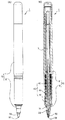
本実施の第1の形態に係るボールペン1は、図1(A)及び(B)に示すように、筆記ボール30及び先端をかしめたカシメ部23(図3参照)により前記筆記ボール30を保持するホルダー21を有するボールペンチップ20と、ボールペンチップ20のホルダー21にインクを供給するインク供給部40と、インク供給部40を内部に収納する軸筒10と、ホルダー21の外周を覆うアウター50とを備えている。
Hereinafter, embodiments of the present invention will be described by dividing the first embodiment to the fifth embodiment with reference to the drawings. In the present specification, “front” of the ballpoint pen 1 and its component parts means the tip side when the writing
(First embodiment)
As shown in FIGS. 1A and 1B, the ballpoint pen 1 according to the first embodiment holds the writing
軸筒10は、図1(B)に示すように、インク収容部13を備えた軸本体11と、軸本体11の先端に設けられた先軸部12とからなり、軸本体11の先端側には、インク供給部40と、インク供給部40とボールペンチップ20とをつなぐ継ぎ手14とが内蔵されている。前記インク収容部13には、図示しないインクが充填されている。
インク供給部40は、複数のフィンが外周に形成された略筒状のコレクター41と、コレクター41の先端を縮径して形成された先端保持部42とを有し、コレクター41の後端部はインク収容部13と接し、先端保持部42は先軸部12の内側に嵌入されている。また、先端保持部42の内部には、継ぎ手14の後端部が嵌入されている。また、コレクター41には、ポリエステルファイバー製の棒状のコレクター芯43が、軸方向に貫通している。コレクター芯43の後端側はインク収容部13内に突出しており、コレクター芯43の先端側は先端保持部42よりも先端側に突出して、継ぎ手14の後端部から内部に挿入されている。
As shown in FIG. 1B, the
The
ボールペンチップ20は、図2に示すように、円筒形のホルダー21と、ホルダー21に保持される筆記ボール30とを備えている。ホルダー21の先端側には、先端に向かって先細となる略円錐状のテーパー部22が形成されているとともに、テーパー部22の小口を内方に押圧して縮径変形されたカシメ部23が形成されている。そして、テーパー部22の内側に形成されたボールハウス24(図3参照)に抱持される筆記ボール30の先端部が、カシメ部23の先端縁から露出するようになっている。ホルダー21はステンレス鋼などの金属製やポリアセタールなどの樹脂製のパイプ材を加工して形成することができる。また、ホルダー21の内部には、ホルダー21の後端部から突出する棒状の中芯25が挿入されている。中芯25はコレクター芯43と同様にポリエステルファイバーにより形成され、その後端はコレクター芯43の先端部に嵌め込まれるとともに、その先端は筆記ボール30の直後に達しており、コレクター芯43に浸透したインクを吸収してボールハウス24にインクを供給する。ボールペンチップ20は、図2に示すように、後端側からほぼ2/3程度が継ぎ手14の先端部に嵌入された状態で、継ぎ手14に保持される。
As shown in FIG. 2, the
なお、コレクター芯43及び中芯25は、使用するインクの粘度等の性状に応じて、適切なポリエステルファイバーの気孔率や表面形状を選択して形成される。
アウター50は、略円錐形に形成された合成樹脂製の筒体であり、図2に示すように、先端に向かって先細となるテーパー部54が形成されているとともに、テーパー部54の先端部分は、R面取りが施されたアウター先端部51となっている。なお、アウター先端部51は、R面取りでなく、斜面状のテーパー面取りにしてもよい。また、後方側に形成された後方挿入孔52と、後方挿入孔52から先端側に連通する後方挿入孔52よりも小径の前方挿入孔53を有し、後方挿入孔52には継ぎ手14の先端部が挿入され、前方挿入孔53には、継ぎ手14から突出しているボールペンチップ20のホルダー21が挿入される。そして、アウター50は、前方挿入孔53にホルダー21が挿入され後方挿入孔52に継ぎ手14の先端部が挿入された状態で、継ぎ手14の先端部に固定され、先軸部12から露出している継ぎ手14及びホルダー21を覆うようになっている。
The
The outer 50 is a cylindrical body made of synthetic resin formed in a substantially conical shape. As shown in FIG. 2, a tapered
また、アウター50が継ぎ手14に固定されると、図3に示すように、アウター先端部51の最も先端側(前方挿入孔53の先端側縁部)が、ホルダー21のテーパー部22とカシメ部23の境界線をやや超えた箇所まで位置するようになっている。すなわち、アウター50は、ホルダー21のカシメ部23に達する部分までを覆うようになっている。これにより、図1、2に示すように、先軸部12の先端からは、アウター50の先端側約2/3と、ホルダー21のカシメ部23と、筆記ボール30の一部が露出することとなる。なお、アウターは継ぎ手14に固定されてもよいし、先軸部12と一体的に形成することもできる。
ここにおいて、アウター50のアウター先端部51は、図3に示すように、アウター先端部51と筆記ボール30との双方に接する接線Lよりも、カシメ部23が内側(筆記ボール30側)に位置するよう、カシメ部23の外側に膨出した形状に形成されている。換言すると、アウター先端部51は、カシメ部23が前記接線Lよりも前方に突出しないように形成されている。このように形成されていることから、筆記ボール30とアウター先端部51を同時に筆記面に当接させた場合に、筆記ボール30の表面に付着しているインクや筆記ボール30の回転に伴いボールハウス24から流出するインクが、筆記ボール30と筆記面の接触部と、アウター先端部51と筆記面の接触部との間の空間部に、毛細管現象により拡散して、筆記ボール30とアウター先端部51を同時に筆記面に当接させない場合よりも、太い線を描くことが可能となる。
When the outer 50 is fixed to the joint 14, as shown in FIG. 3, the most distal end side of the outer distal end portion 51 (the distal end side edge of the front insertion hole 53) is the tapered
Here, as shown in FIG. 3, the outer
本実施の形態においては、筆記ボール30とアウター先端部51が同時に筆記面に接触した状態で、筆記ボール30と筆記面の接触部と、アウター先端部51と筆記面の接触部との間に拡散可能な、比較的粘度の低いインクが用いられている。このようなインクを用いることにより、太い描線を描く場合でもかすれることがない。
上記構成を有するボールペン1の使用方法について、図4から図6までに基づき説明する。
図4(A)に示すように、アウター50のテーパー部54の筆記面に対する角度がa°となるようにボールペン1を傾斜させた場合には、図5に示すように、筆記ボール30のみを筆記面に接触させることができる。このような角度でボールペン1を傾斜させて筆記した場合には、筆記ボール30の表面に付着したインクによって、幅w1の線を描くことができる。
In the present embodiment, the writing
A method of using the ballpoint pen 1 having the above configuration will be described with reference to FIGS.
As shown in FIG. 4A, when the ballpoint pen 1 is tilted so that the angle of the tapered
一方、図4(B)に示すように、アウター50のテーパー部54の筆記面に対する角度が前記a°より小さいb°となるようにボールペン1を傾斜させた場合には、図6に示すように、筆記ボール30とアウター先端部51を同時に筆記面に接触させることができる。この状態では、筆記ボール30の表面に付着しているインクが毛細管現象により筆記面に拡散してアウター先端部51にも付着し、筆記ボール30と筆記面とアウター先端部51とカシメ部23により囲まれた空間部にインクが滞留する。そして、このような状態で筆記した場合には、筆記ボール30の回転に伴い前記した空間部にインクが流出し、筆記ボール30と筆記面の接触部とアウター先端部51と筆記面の接触部の間に拡散するインクによって、前記した幅w1よりも大きい幅w2の線を描くことができる。この場合において、筆記ボール30とカシメ部23との位置関係は保持されているため、筆記ボール30の回転に伴い流出するインク量を一定に保つことができ、インクがぼた漏れすることもない。また筆記面との接触部の変化は角度だけではなく、先端部の紙面への接触状態でも同様とすることができる。例えば複数の紙面を重ねた状態で、荷重を弱くして筆記すれば筆記ボールのみが筆記面に接触するので、幅w1の線を書くことができ、荷重を強くして筆記すれば筆記ボールとアウター先端部が筆記面に同時に接触させることができるので、幅w1より顕著に太い幅w2の線を書くことができる。
On the other hand, as shown in FIG. 4B, when the ballpoint pen 1 is inclined so that the angle of the tapered
以上のように、本実施の形態に係るボールペン1は、筆記する際の筆記面に対する角度や筆記部と紙面との接触状態を変えるだけで、顕著に描線の太さを変えることができ、「トメ」、「ハネ」、「ハライ」等徐々に描線を細くすることができる。すなわち、細い線を描く場合には、図4(A)に示すように、軸筒10を垂直に近い状態(立てた状態)にし、太い線を描く場合には、図4(B)に示すように、細い線を描く場合よりも軸筒10を傾斜した状態(寝かせた状態)とすればよい。
なお、アウター50のアウター先端部51の形状(前方への突出寸法又は側方への張り出し寸法)を調節することにより、筆記ボール30のボール径が異なる場合であっても、筆記ボール30とアウター先端部51が同時に筆記面に接触したときの線幅を同じ寸法にすることができる。
As described above, the ballpoint pen 1 according to the present embodiment can remarkably change the thickness of the drawn line only by changing the angle with respect to the writing surface at the time of writing or the contact state between the writing portion and the paper surface. The strokes can be gradually made thinner, such as “Tome”, “Hane”, and “Harai”. That is, when drawing a thin line, as shown in FIG. 4 (A), the
Even if the ball diameter of the writing
(第2の実施の形態)
図7から図13までは、本発明の第2の実施の形態を示す。なお、第2の実施の形態において、第1の実施の形態と同一の構成要素には、第1の実施の形態において用いた符号と同一の符号を用いている。以下、第3から第5までの実施の形態についても同様である。
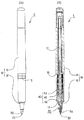
第2の実施の形態に係るボールペン1は、図7(A)及び(B)に示すように、筆記ボール30及び先端をかしめたカシメ部23(図9参照)により前記筆記ボール30を保持するホルダー21を有するボールペンチップ20と、ボールペンチップ20のホルダー21にインクを供給するインク供給部40と、インク供給部40を内部に収納する軸筒10と、ホルダー21の外周を覆うアウター50とを備え、またボールペンチップ20の先端部の保護のためキャップ60が装着されている。以下、第1の実施の形態と重複する部分は説明を省略し、本実施の形態の特徴点を説明する。
(Second Embodiment)
7 to 13 show a second embodiment of the present invention. In the second embodiment, the same reference numerals as those used in the first embodiment are used for the same constituent elements as those in the first embodiment. Hereinafter, the same applies to the third to fifth embodiments.
As shown in FIGS. 7A and 7B, the ballpoint pen 1 according to the second embodiment holds the writing
前記キャップ60は、図7(A)に示すように、軸筒10の先端側略3分の1程度を覆っており、図7(B)に示すように、合成樹脂製の筒体61と、筒体61の先端側から嵌め込まれる蓋部材62から構成され、内部にペン先収納部63を備えている。キャップ60を軸筒10の先端に被せると、軸本体11の直径を縮径して形成された段部15(図8参照)に筒体61の後端部61Aが係止され、ペン先収納部63にボールペンチップ20の先端部が位置するようになっている。
本実施の形態においては、図9に示すように、中芯25は、コレクター芯43の先端面に形成された凹部43Aの凹底面と僅かながら離間している。また、継ぎ手14の、先端保持部42からの突出部分には、軸方向に沿った縦溝14Aが、断面放射状に形成されている。
As shown in FIG. 7A, the
In the present embodiment, as shown in FIG. 9, the
さらに、本実施の形態におけるアウター50は、図9に示すように、直径を縮径して形成された段部56が、先軸部12の先端部とほぼ同じ位置かやや先端側に位置するように配置されている。また、図10に示すように、アウター50のテーパー部54の先端部には、先端に向かって先細となる面取り部55が形成されており、この面取り部55の先端部分が、筆記ボール30と同時に筆記面に当接するR面取りが施されたアウター先端部51となっている。なお、アウター先端部51は、R面取りでなく、斜面状のテーパー面取りにしてもよい。
第2の実施の形態に係るボールペン1によっても、第1の実施の形態と同様の作用効果を得ることができる。すなわち、図11(A)に示すように、アウター50のテーパー部54の筆記面に対する角度がa°となるようにボールペン1を傾斜させた場合には、図12に示すように、筆記ボール30のみを筆記面に接触させ、幅w1の線を描くことができる。また、図11(B)に示すように、アウター50のテーパー部54の筆記面に対する角度が前記a°より小さいb°となるようにボールペン1を傾斜させた場合には、図13に示すように、筆記ボール30とアウター先端部51を同時に筆記面に接触させ、前記した幅w1よりも大きい幅w2の線を描くことができる(図11から図13まで参照)。
Furthermore, as shown in FIG. 9, the outer 50 in the present embodiment has a stepped
Also with the ballpoint pen 1 according to the second embodiment, the same effect as the first embodiment can be obtained. That is, as shown in FIG. 11A, when the ballpoint pen 1 is inclined so that the angle of the tapered
(第3の実施の形態)
図14から図16までは、本発明の第3の実施の形態を示す。なお、第3の実施の形態において、第2の実施の形態と同一部品については同一の符号を用いている(第4及び第5の実施の形態において同じ)。以下、第1及び第2の実施の形態と重複する部分は説明を省略し、本実施の形態の特徴を説明する。
第3の実施の形態に係るボールペン1は、図14(A)及び(B)に示すように、ボールペンチップ20が固定されたインクリフィル70を、軸筒10に収納したものであり、ボールペンチップ20の先端部の保護のためキャップ60が装着されている。
(Third embodiment)
14 to 16 show a third embodiment of the present invention. In the third embodiment, the same reference numerals are used for the same components as those in the second embodiment (the same applies in the fourth and fifth embodiments). Hereinafter, the description of the same parts as those in the first and second embodiments will be omitted, and the features of the present embodiment will be described.
As shown in FIGS. 14 (A) and 14 (B), the ballpoint pen 1 according to the third embodiment is configured such that an
本実施の形態におけるボールペンチップ20は、図15(B)及び図16に示すように、円筒形のホルダー21の先端部に縮径部21Aが形成され、この縮径部21Aの先端に、テーパー部22及びカシメ部23が設けられ、筆記ボール30が抱持されている。ホルダー21の内部は中空である。
キャップ60は、図14(A)に示すように、軸筒10の先端側の略4分の1程度を覆っており、図14(B)に示すように、合成樹脂製の筒体61と、筒体61の先端側から嵌め込まれる蓋部材62から構成され、内部にペン先収納部63を備えている。キャップ60を軸筒10の先端に被せると、軸本体11の直径を縮径して形成された段差15に筒体61の後端部61Aが係止され、ペン先収納部63にボールペンチップ20の先端部が位置するようになっている。
As shown in FIGS. 15B and 16, the ball-
As shown in FIG. 14A, the
インクリフィル70は、図15(A)及び(B)に示すように、インクが充填されたインク収容管71と、インク収容管71の先端に固定された継ぎ手72と、継ぎ手72に固定されたボールペンチップ20とからなる。インク収容管71は、図示しないインク及びインク漏出防止のためのインク追従体が充填されたポリプロピレン製の管である。継ぎ手72は、前後に貫通する開口部を有し、後方部分をインク収容管71の内部に圧入して装着される筒状部材である。インク収容管71から露出する継ぎ手72の前方部分の開口部にはボールペンチップ20が圧入され、インク収容管71のインクが後方部分の開口部からボールペンチップ20に供給される。インクリフィル70は、図14(B)に示すように、インク収容管71が軸本体11の内部に収納され、継ぎ手71及び継ぎ手71から露出しているボールペンチップ20は先軸部12によって覆われる。
As shown in FIGS. 15A and 15B, the
本実施の形態においては、アウター50は、図16に示すように、ホルダー21の縮径部21Aを後方から挿入可能な挿入口57を有し、この挿入口57にホルダー21の縮径部21Aが挿入された状態で、ホルダー21の先端部に固定されホルダー21を覆うようになっている。そして、インクリフィル70を軸筒10に収納すると、図14(B)に示すように、アウター50が先軸部12の先端から露出するようになっている。
第3の実施の形態に係るボールペン1によっても、第1の実施の形態と同様の作用効果を得ることができる。そして、本実施の形態においては、第1の実施の形態、第2の実施の形態と異なり、インクリフィル70のインクが無くなり、筆記できなくなったら、インクリフィル70を交換することで新たに筆記することができる。
In the present embodiment, as shown in FIG. 16, the outer 50 has an
Also with the ballpoint pen 1 according to the third embodiment, it is possible to obtain the same functions and effects as those of the first embodiment. In this embodiment, unlike the first embodiment and the second embodiment, when the ink of the
(第4の実施の形態)
図17及び図18は、本発明の第4の実施の形態を示す。以下、第1から第3までの実施の形態と重複する部分は説明を省略し、本実施の形態の特徴を説明する。
第4の実施の形態に係るボールペン1は、図17(A)及び(B)に示すように、ボールペンチップ20が固定されたインクリフィル70を、軸筒10に収納したものである。なお、図示しないが、ボールペンチップ20の先端部の保護のためキャップを有していてもよい。
そして、本実施の形態においては、軸筒10の先端部には、先端に向かって先細に形成された略円錐形のアウター50が取り付けられている。アウター50の内部は後側から先端側に貫通する挿入孔57となっており、図17(B)及び図18に示すように、挿入孔57の後側の孔内周面にはネジ部57Aが形成されている。そして、このネジ部57Aを、軸本体11の先端側外周に形成されたネジ部11Aと螺合させることにより、アウター50が固定されるとともに、継ぎ手71及び継ぎ手71から露出するボールペンチップ20を覆うようになっている。すなわち、本実施の形態では、アウター50が先軸部を兼ねているものである。
(Fourth embodiment)
17 and 18 show a fourth embodiment of the present invention. Hereinafter, the description of the same parts as those in the first to third embodiments will be omitted, and the features of the present embodiment will be described.
As shown in FIGS. 17A and 17B, the ballpoint pen 1 according to the fourth embodiment is one in which an
In the present embodiment, a substantially conical outer 50 that is tapered toward the tip is attached to the tip of the
第4の実施の形態によれば、上記した実施の形態と同様の作用効果を得られるとともに、部品点数を削減でき、製品の組み立て工程を簡易化することができる。
(第5の実施の形態)
図19及び図20は、本発明の第5の実施の形態を示す。本実施の形態は、第4の実施の形態の筆記ボール30よりも大径の筆記ボール30を有するボールペン1である。ボールペンチップ20の先端部の径が第4の実施の形態のものよりも大きいので、アウター50のテーパーが緩やかになっているとともに、アウター50の先端部に角度の異なるテーパー部が設けられている点以外は、第4の形態と同様である。
According to the fourth embodiment, the same effects as those of the above-described embodiment can be obtained, the number of parts can be reduced, and the product assembly process can be simplified.
(Fifth embodiment)
19 and 20 show a fifth embodiment of the present invention. The present embodiment is a ballpoint pen 1 having a writing
(他の筆記具との比較例)
図21は、ボールペン、サインペン、万年筆と、本発明に係るボールペン1で筆記した筆跡である。本発明に係るボールペン1で筆記した筆跡は、ボールペン、サインペン、万年筆と比べ、画の終わりであるα「トメ」β「ハネ」γ「ハライ」を容易かつ高品位で筆記することができる。
このように、上記した第1から第5までの実施の形態においては、ボールペンチップ20とアウター50によって、1つの筆記先端で異なる太さの描線を筆記することができるとともに、筆跡の表現力も向上させることができる。
(Comparative example with other writing instruments)
FIG. 21 is a handwriting written with a ballpoint pen, a sign pen, a fountain pen, and the ballpoint pen 1 according to the present invention. The handwriting written with the ballpoint pen 1 according to the present invention can be easily and high-quality written with α “Tome” β “Hane” γ “Halai” at the end of the image, compared with a ballpoint pen, a sign pen, and a fountain pen.
Thus, in the first to fifth embodiments described above, the
この発明は、ボールペンなどの筆記具に利用することができる。 The present invention can be used for a writing instrument such as a ballpoint pen.
1 ボールペン
10 軸筒 11 軸本体 12 先軸部
13 インク収容部 14 継ぎ手 15 段差
20 ボールペンチップ 21 ホルダー 22 テーパー部
23 カシメ部 24 ボールハウス 25 中芯
30 筆記ボール
40 インク供給部 41 コレクター 42 先端保持部
43 コレクター芯 43A 凹部
50 アウター 51 アウター先端部 52 後方挿入孔
53 前方挿入孔 54 テーパー部 55 面取り部
56 段部 57 挿入口
60 キャップ 61 筒体 62 蓋部材
63 ペン先収納部
70 インクリフィル 71 インク収容管 72 継ぎ手
1 Ballpoint pen
10
13
20
23
30 writing balls
40
43
50
53
56
60
63 Nib storage area
70
Claims (4)
筆記ボールと、先端をかしめたカシメ部により前記筆記ボールを保持するホルダーと、ホルダーにインクを供給するインク供給部と、インク供給部を内部に収納する軸筒と、前記ホルダーの外周を覆うアウターとを備え、前記筆記ボールを保持したホルダー及び前記アウターの一部を前記軸筒の先端部より露出させてなり、
前記筆記ボールとアウター先端部が筆記部となることを特徴とするボールペン。 A ballpoint pen capable of writing strokes of different thickness at the tip of a writing ,
A writing ball, a holder for holding the writing ball by a caulking portion crimped at a tip thereof, an ink supply portion for supplying ink to the holder, a shaft cylinder for accommodating the ink supply portion therein, and an outer covering the outer periphery of the holder The holder holding the writing ball and a part of the outer are exposed from the tip of the shaft tube,
A ballpoint pen characterized in that the writing ball and outer tip end portion become a writing portion .
筆記ボールと、先端をかしめたカシメ部により前記筆記ボールを保持するホルダーと、ホルダーにインクを供給するインク供給部と、インク供給部を内部に収納する軸筒と、前記軸筒と一体に成形され該軸筒の先端部を構成するとともに前記ホルダーの外周を覆うアウターとを備え、前記筆記ボールを保持したホルダーの一部を前記アウターの先端部より露出させてなり、
前記筆記ボールとアウター先端部が筆記部となることを特徴とするボールペン。 A ballpoint pen capable of writing strokes of different thickness at the tip of a writing,
A writing ball, a holder for holding the writing ball by a crimped portion crimped at the tip, an ink supply unit for supplying ink to the holder, a shaft cylinder for storing the ink supply unit therein, and a single unit with the shaft tube is provided with an outer covering the outer periphery of the holder as well as constituting a distal portion of the shaft barrel, it will be a part of the holder over holding the writing ball is exposed from the outer tip portion,
Features and to Rubo Rupen said writing ball and the outer tip is writing unit.
Priority Applications (8)
| Application Number | Priority Date | Filing Date | Title |
|---|---|---|---|
| JP2012129644A JP5940898B2 (en) | 2012-06-07 | 2012-06-07 | Ballpoint pen |
| US14/405,661 US9545813B2 (en) | 2012-06-07 | 2013-06-07 | Ball pen |
| ES13800078.1T ES2691940T3 (en) | 2012-06-07 | 2013-06-07 | Pen |
| PCT/JP2013/065782 WO2013183744A1 (en) | 2012-06-07 | 2013-06-07 | Ball pen |
| EP13800078.1A EP2860045B1 (en) | 2012-06-07 | 2013-06-07 | Ballpoint pen |
| CN201380041400.0A CN104640712B (en) | 2012-06-07 | 2013-06-07 | Ball pen |
| TW102120333A TWI635967B (en) | 2012-06-07 | 2013-06-07 | Ball-point pen |
| KR1020147034428A KR102121083B1 (en) | 2012-06-07 | 2013-06-07 | Ball pen |
Applications Claiming Priority (1)
| Application Number | Priority Date | Filing Date | Title |
|---|---|---|---|
| JP2012129644A JP5940898B2 (en) | 2012-06-07 | 2012-06-07 | Ballpoint pen |
Publications (3)
| Publication Number | Publication Date |
|---|---|
| JP2013252654A JP2013252654A (en) | 2013-12-19 |
| JP2013252654A5 JP2013252654A5 (en) | 2015-08-13 |
| JP5940898B2 true JP5940898B2 (en) | 2016-06-29 |
Family
ID=49950591
Family Applications (1)
| Application Number | Title | Priority Date | Filing Date |
|---|---|---|---|
| JP2012129644A Active JP5940898B2 (en) | 2012-06-07 | 2012-06-07 | Ballpoint pen |
Country Status (1)
| Country | Link |
|---|---|
| JP (1) | JP5940898B2 (en) |
Cited By (5)
| Publication number | Priority date | Publication date | Assignee | Title |
|---|---|---|---|---|
| USD896183S1 (en) | 2018-01-08 | 2020-09-15 | Samtec, Inc. | Electrical cable connector |
| US11289850B2 (en) | 2017-07-21 | 2022-03-29 | Samtec, Inc. | Electrical connector having latch |
| USD964291S1 (en) | 2017-07-21 | 2022-09-20 | Samtec, Inc. | Electrical connector |
| US11495917B2 (en) | 2017-10-24 | 2022-11-08 | Samtec, Inc. | Right-angle electrical connector and electrical contacts for a right-angle connector |
| US11637400B2 (en) | 2017-06-13 | 2023-04-25 | Samtec, Inc. | Electrical cable connector |
Families Citing this family (6)
| Publication number | Priority date | Publication date | Assignee | Title |
|---|---|---|---|---|
| JP2016141003A (en) * | 2015-01-30 | 2016-08-08 | 三菱鉛筆株式会社 | Ball point pen |
| EP3375625A4 (en) * | 2015-11-09 | 2019-06-19 | Mitsubishi Pencil Company, Limited | Ballpoint pen |
| US10155410B2 (en) | 2015-12-01 | 2018-12-18 | Zebra Co., Ltd. | Ballpoint pen chip and writing utensil equipped with the ballpoint pen chip |
| JP6944880B2 (en) | 2015-12-28 | 2021-10-06 | 三菱鉛筆株式会社 | Writing implements |
| KR102299962B1 (en) | 2016-06-09 | 2021-09-07 | 제브라 가부시키가이샤 | Ballpoint pen chip and writing utensil equipped with the ballpoint pen chip |
| JP6735170B2 (en) * | 2016-07-21 | 2020-08-05 | 三菱鉛筆株式会社 | Writing instrument |
Family Cites Families (6)
| Publication number | Priority date | Publication date | Assignee | Title |
|---|---|---|---|---|
| DE1511403A1 (en) * | 1966-06-23 | 1969-06-19 | Pelikan Werke Wagner Guenther | Writing instrument with capillary gap |
| JPS4844283Y1 (en) * | 1968-09-30 | 1973-12-20 | ||
| JPS526348Y2 (en) * | 1972-12-28 | 1977-02-09 | ||
| DE3914465A1 (en) * | 1989-05-02 | 1990-11-08 | Merz & Krell | WRITING DEVICE |
| US8104983B2 (en) * | 2003-11-11 | 2012-01-31 | Societe Bic | Combination writing instrument |
| JP2009143032A (en) * | 2007-12-12 | 2009-07-02 | Pilot Ink Co Ltd | Ball-point pen |
-
2012
- 2012-06-07 JP JP2012129644A patent/JP5940898B2/en active Active
Cited By (8)
| Publication number | Priority date | Publication date | Assignee | Title |
|---|---|---|---|---|
| US11637400B2 (en) | 2017-06-13 | 2023-04-25 | Samtec, Inc. | Electrical cable connector |
| US11289850B2 (en) | 2017-07-21 | 2022-03-29 | Samtec, Inc. | Electrical connector having latch |
| USD964291S1 (en) | 2017-07-21 | 2022-09-20 | Samtec, Inc. | Electrical connector |
| US11626689B2 (en) | 2017-07-21 | 2023-04-11 | Samtec, Inc. | Electrical connector having latch |
| USD1005964S1 (en) | 2017-07-21 | 2023-11-28 | Samtec, Inc. | Electrical connector |
| US11495917B2 (en) | 2017-10-24 | 2022-11-08 | Samtec, Inc. | Right-angle electrical connector and electrical contacts for a right-angle connector |
| USD896183S1 (en) | 2018-01-08 | 2020-09-15 | Samtec, Inc. | Electrical cable connector |
| USD967031S1 (en) | 2018-01-08 | 2022-10-18 | Samtec, Inc. | Electrical cable connector |
Also Published As
| Publication number | Publication date |
|---|---|
| JP2013252654A (en) | 2013-12-19 |
Similar Documents
| Publication | Publication Date | Title |
|---|---|---|
| JP5940898B2 (en) | Ballpoint pen | |
| KR102121083B1 (en) | Ball pen | |
| JP5940899B2 (en) | Ballpoint pen | |
| WO2010104101A1 (en) | Ballpoint pen tip, ballpoint pen refill, ballpoint pen, and method of manufacturing ballpoint pen tip | |
| JP3139171U (en) | Water-based ballpoint pen | |
| WO2015087852A1 (en) | Ballpoint pen | |
| JP2005313404A (en) | Writing utensil | |
| JP6334884B2 (en) | Ballpoint pen | |
| JP6259650B2 (en) | Ballpoint pen | |
| JP4511381B2 (en) | Direct liquid writing instrument | |
| JP6291237B2 (en) | Ballpoint pen | |
| KR100360613B1 (en) | Ballpoint Tip for Liquid Vessel | |
| JPH025981Y2 (en) | ||
| JP3960818B2 (en) | Ballpoint pen | |
| EP3031613B1 (en) | Felt tipped feeding assembly and writing instrument fed from a standard disposable cartridge of aqueous ink | |
| JP2003291582A (en) | Ball type direct liquid writing implement | |
| JP3139355U (en) | Pipe ballpoint pen tip | |
| JP2007144967A (en) | Mechanical pencil with eraser | |
| JP2006240219A (en) | Ball-point pen refill | |
| JP2019162736A (en) | Writing instrument | |
| JP2002362084A (en) | Ballpoint pen | |
| JPH0634985U (en) | Pen | |
| JP2006062341A (en) | Aqueous ball-point pen | |
| JPH07276886A (en) | Writing utensil | |
| JP2006116902A (en) | Direct liquid-type writing utensil group |
Legal Events
| Date | Code | Title | Description |
|---|---|---|---|
| A621 | Written request for application examination |
Free format text: JAPANESE INTERMEDIATE CODE: A621 Effective date: 20150316 |
|
| A521 | Request for written amendment filed |
Free format text: JAPANESE INTERMEDIATE CODE: A523 Effective date: 20150626 |
|
| RD02 | Notification of acceptance of power of attorney |
Free format text: JAPANESE INTERMEDIATE CODE: A7422 Effective date: 20150626 |
|
| TRDD | Decision of grant or rejection written | ||
| A01 | Written decision to grant a patent or to grant a registration (utility model) |
Free format text: JAPANESE INTERMEDIATE CODE: A01 Effective date: 20160426 |
|
| A61 | First payment of annual fees (during grant procedure) |
Free format text: JAPANESE INTERMEDIATE CODE: A61 Effective date: 20160519 |
|
| R150 | Certificate of patent or registration of utility model |
Ref document number: 5940898 Country of ref document: JP Free format text: JAPANESE INTERMEDIATE CODE: R150 |
|
| R250 | Receipt of annual fees |
Free format text: JAPANESE INTERMEDIATE CODE: R250 |
|
| R250 | Receipt of annual fees |
Free format text: JAPANESE INTERMEDIATE CODE: R250 |