EP2860025A1 - Window member in a curved display device, method of manufacturing a window member of a curved display device, and curved display device having the same - Google Patents
Window member in a curved display device, method of manufacturing a window member of a curved display device, and curved display device having the same Download PDFInfo
- Publication number
- EP2860025A1 EP2860025A1 EP20140183961 EP14183961A EP2860025A1 EP 2860025 A1 EP2860025 A1 EP 2860025A1 EP 20140183961 EP20140183961 EP 20140183961 EP 14183961 A EP14183961 A EP 14183961A EP 2860025 A1 EP2860025 A1 EP 2860025A1
- Authority
- EP
- European Patent Office
- Prior art keywords
- curvature
- radius
- window body
- window
- curved
- Prior art date
- Legal status (The legal status is an assumption and is not a legal conclusion. Google has not performed a legal analysis and makes no representation as to the accuracy of the status listed.)
- Granted
Links
Images




Classifications
-
- B—PERFORMING OPERATIONS; TRANSPORTING
- B29—WORKING OF PLASTICS; WORKING OF SUBSTANCES IN A PLASTIC STATE IN GENERAL
- B29C—SHAPING OR JOINING OF PLASTICS; SHAPING OF MATERIAL IN A PLASTIC STATE, NOT OTHERWISE PROVIDED FOR; AFTER-TREATMENT OF THE SHAPED PRODUCTS, e.g. REPAIRING
- B29C39/00—Shaping by casting, i.e. introducing the moulding material into a mould or between confining surfaces without significant moulding pressure; Apparatus therefor
- B29C39/02—Shaping by casting, i.e. introducing the moulding material into a mould or between confining surfaces without significant moulding pressure; Apparatus therefor for making articles of definite length, i.e. discrete articles
- B29C39/12—Making multilayered or multicoloured articles
-
- B—PERFORMING OPERATIONS; TRANSPORTING
- B29—WORKING OF PLASTICS; WORKING OF SUBSTANCES IN A PLASTIC STATE IN GENERAL
- B29C—SHAPING OR JOINING OF PLASTICS; SHAPING OF MATERIAL IN A PLASTIC STATE, NOT OTHERWISE PROVIDED FOR; AFTER-TREATMENT OF THE SHAPED PRODUCTS, e.g. REPAIRING
- B29C45/00—Injection moulding, i.e. forcing the required volume of moulding material through a nozzle into a closed mould; Apparatus therefor
- B29C45/0001—Injection moulding, i.e. forcing the required volume of moulding material through a nozzle into a closed mould; Apparatus therefor characterised by the choice of material
-
- B—PERFORMING OPERATIONS; TRANSPORTING
- B29—WORKING OF PLASTICS; WORKING OF SUBSTANCES IN A PLASTIC STATE IN GENERAL
- B29C—SHAPING OR JOINING OF PLASTICS; SHAPING OF MATERIAL IN A PLASTIC STATE, NOT OTHERWISE PROVIDED FOR; AFTER-TREATMENT OF THE SHAPED PRODUCTS, e.g. REPAIRING
- B29C65/00—Joining or sealing of preformed parts, e.g. welding of plastics materials; Apparatus therefor
- B29C65/48—Joining or sealing of preformed parts, e.g. welding of plastics materials; Apparatus therefor using adhesives, i.e. using supplementary joining material; solvent bonding
- B29C65/4855—Joining or sealing of preformed parts, e.g. welding of plastics materials; Apparatus therefor using adhesives, i.e. using supplementary joining material; solvent bonding characterised by their physical properties, e.g. being electrically-conductive
-
- B—PERFORMING OPERATIONS; TRANSPORTING
- B32—LAYERED PRODUCTS
- B32B—LAYERED PRODUCTS, i.e. PRODUCTS BUILT-UP OF STRATA OF FLAT OR NON-FLAT, e.g. CELLULAR OR HONEYCOMB, FORM
- B32B1/00—Layered products having a non-planar shape
-
- B—PERFORMING OPERATIONS; TRANSPORTING
- B32—LAYERED PRODUCTS
- B32B—LAYERED PRODUCTS, i.e. PRODUCTS BUILT-UP OF STRATA OF FLAT OR NON-FLAT, e.g. CELLULAR OR HONEYCOMB, FORM
- B32B27/00—Layered products comprising a layer of synthetic resin
- B32B27/06—Layered products comprising a layer of synthetic resin as the main or only constituent of a layer, which is next to another layer of the same or of a different material
- B32B27/08—Layered products comprising a layer of synthetic resin as the main or only constituent of a layer, which is next to another layer of the same or of a different material of synthetic resin
-
- B—PERFORMING OPERATIONS; TRANSPORTING
- B32—LAYERED PRODUCTS
- B32B—LAYERED PRODUCTS, i.e. PRODUCTS BUILT-UP OF STRATA OF FLAT OR NON-FLAT, e.g. CELLULAR OR HONEYCOMB, FORM
- B32B27/00—Layered products comprising a layer of synthetic resin
- B32B27/28—Layered products comprising a layer of synthetic resin comprising synthetic resins not wholly covered by any one of the sub-groups B32B27/30 - B32B27/42
- B32B27/281—Layered products comprising a layer of synthetic resin comprising synthetic resins not wholly covered by any one of the sub-groups B32B27/30 - B32B27/42 comprising polyimides
-
- B—PERFORMING OPERATIONS; TRANSPORTING
- B32—LAYERED PRODUCTS
- B32B—LAYERED PRODUCTS, i.e. PRODUCTS BUILT-UP OF STRATA OF FLAT OR NON-FLAT, e.g. CELLULAR OR HONEYCOMB, FORM
- B32B27/00—Layered products comprising a layer of synthetic resin
- B32B27/30—Layered products comprising a layer of synthetic resin comprising vinyl (co)polymers; comprising acrylic (co)polymers
- B32B27/308—Layered products comprising a layer of synthetic resin comprising vinyl (co)polymers; comprising acrylic (co)polymers comprising acrylic (co)polymers
-
- B—PERFORMING OPERATIONS; TRANSPORTING
- B32—LAYERED PRODUCTS
- B32B—LAYERED PRODUCTS, i.e. PRODUCTS BUILT-UP OF STRATA OF FLAT OR NON-FLAT, e.g. CELLULAR OR HONEYCOMB, FORM
- B32B27/00—Layered products comprising a layer of synthetic resin
- B32B27/36—Layered products comprising a layer of synthetic resin comprising polyesters
-
- B—PERFORMING OPERATIONS; TRANSPORTING
- B32—LAYERED PRODUCTS
- B32B—LAYERED PRODUCTS, i.e. PRODUCTS BUILT-UP OF STRATA OF FLAT OR NON-FLAT, e.g. CELLULAR OR HONEYCOMB, FORM
- B32B27/00—Layered products comprising a layer of synthetic resin
- B32B27/36—Layered products comprising a layer of synthetic resin comprising polyesters
- B32B27/365—Layered products comprising a layer of synthetic resin comprising polyesters comprising polycarbonates
-
- B—PERFORMING OPERATIONS; TRANSPORTING
- B32—LAYERED PRODUCTS
- B32B—LAYERED PRODUCTS, i.e. PRODUCTS BUILT-UP OF STRATA OF FLAT OR NON-FLAT, e.g. CELLULAR OR HONEYCOMB, FORM
- B32B7/00—Layered products characterised by the relation between layers; Layered products characterised by the relative orientation of features between layers, or by the relative values of a measurable parameter between layers, i.e. products comprising layers having different physical, chemical or physicochemical properties; Layered products characterised by the interconnection of layers
- B32B7/04—Interconnection of layers
- B32B7/12—Interconnection of layers using interposed adhesives or interposed materials with bonding properties
-
- E—FIXED CONSTRUCTIONS
- E04—BUILDING
- E04C—STRUCTURAL ELEMENTS; BUILDING MATERIALS
- E04C2/00—Building elements of relatively thin form for the construction of parts of buildings, e.g. sheet materials, slabs, or panels
- E04C2/02—Building elements of relatively thin form for the construction of parts of buildings, e.g. sheet materials, slabs, or panels characterised by specified materials
- E04C2/10—Building elements of relatively thin form for the construction of parts of buildings, e.g. sheet materials, slabs, or panels characterised by specified materials of wood, fibres, chips, vegetable stems, or the like; of plastics; of foamed products
- E04C2/20—Building elements of relatively thin form for the construction of parts of buildings, e.g. sheet materials, slabs, or panels characterised by specified materials of wood, fibres, chips, vegetable stems, or the like; of plastics; of foamed products of plastics
-
- E—FIXED CONSTRUCTIONS
- E04—BUILDING
- E04C—STRUCTURAL ELEMENTS; BUILDING MATERIALS
- E04C2/00—Building elements of relatively thin form for the construction of parts of buildings, e.g. sheet materials, slabs, or panels
- E04C2/02—Building elements of relatively thin form for the construction of parts of buildings, e.g. sheet materials, slabs, or panels characterised by specified materials
- E04C2/10—Building elements of relatively thin form for the construction of parts of buildings, e.g. sheet materials, slabs, or panels characterised by specified materials of wood, fibres, chips, vegetable stems, or the like; of plastics; of foamed products
- E04C2/24—Building elements of relatively thin form for the construction of parts of buildings, e.g. sheet materials, slabs, or panels characterised by specified materials of wood, fibres, chips, vegetable stems, or the like; of plastics; of foamed products laminated and composed of materials covered by two or more of groups E04C2/12, E04C2/16, E04C2/20
-
- E—FIXED CONSTRUCTIONS
- E04—BUILDING
- E04C—STRUCTURAL ELEMENTS; BUILDING MATERIALS
- E04C2/00—Building elements of relatively thin form for the construction of parts of buildings, e.g. sheet materials, slabs, or panels
- E04C2/54—Slab-like translucent elements
-
- H—ELECTRICITY
- H05—ELECTRIC TECHNIQUES NOT OTHERWISE PROVIDED FOR
- H05K—PRINTED CIRCUITS; CASINGS OR CONSTRUCTIONAL DETAILS OF ELECTRIC APPARATUS; MANUFACTURE OF ASSEMBLAGES OF ELECTRICAL COMPONENTS
- H05K5/00—Casings, cabinets or drawers for electric apparatus
- H05K5/02—Details
- H05K5/03—Covers
-
- B—PERFORMING OPERATIONS; TRANSPORTING
- B29—WORKING OF PLASTICS; WORKING OF SUBSTANCES IN A PLASTIC STATE IN GENERAL
- B29K—INDEXING SCHEME ASSOCIATED WITH SUBCLASSES B29B, B29C OR B29D, RELATING TO MOULDING MATERIALS OR TO MATERIALS FOR MOULDS, REINFORCEMENTS, FILLERS OR PREFORMED PARTS, e.g. INSERTS
- B29K2033/00—Use of polymers of unsaturated acids or derivatives thereof as moulding material
- B29K2033/04—Polymers of esters
- B29K2033/08—Polymers of acrylic acid esters, e.g. PMA, i.e. polymethylacrylate
-
- B—PERFORMING OPERATIONS; TRANSPORTING
- B29—WORKING OF PLASTICS; WORKING OF SUBSTANCES IN A PLASTIC STATE IN GENERAL
- B29K—INDEXING SCHEME ASSOCIATED WITH SUBCLASSES B29B, B29C OR B29D, RELATING TO MOULDING MATERIALS OR TO MATERIALS FOR MOULDS, REINFORCEMENTS, FILLERS OR PREFORMED PARTS, e.g. INSERTS
- B29K2067/00—Use of polyesters or derivatives thereof, as moulding material
- B29K2067/003—PET, i.e. poylethylene terephthalate
-
- B—PERFORMING OPERATIONS; TRANSPORTING
- B29—WORKING OF PLASTICS; WORKING OF SUBSTANCES IN A PLASTIC STATE IN GENERAL
- B29K—INDEXING SCHEME ASSOCIATED WITH SUBCLASSES B29B, B29C OR B29D, RELATING TO MOULDING MATERIALS OR TO MATERIALS FOR MOULDS, REINFORCEMENTS, FILLERS OR PREFORMED PARTS, e.g. INSERTS
- B29K2069/00—Use of PC, i.e. polycarbonates or derivatives thereof, as moulding material
-
- B—PERFORMING OPERATIONS; TRANSPORTING
- B29—WORKING OF PLASTICS; WORKING OF SUBSTANCES IN A PLASTIC STATE IN GENERAL
- B29K—INDEXING SCHEME ASSOCIATED WITH SUBCLASSES B29B, B29C OR B29D, RELATING TO MOULDING MATERIALS OR TO MATERIALS FOR MOULDS, REINFORCEMENTS, FILLERS OR PREFORMED PARTS, e.g. INSERTS
- B29K2077/00—Use of PA, i.e. polyamides, e.g. polyesteramides or derivatives thereof, as moulding material
-
- B—PERFORMING OPERATIONS; TRANSPORTING
- B29—WORKING OF PLASTICS; WORKING OF SUBSTANCES IN A PLASTIC STATE IN GENERAL
- B29L—INDEXING SCHEME ASSOCIATED WITH SUBCLASS B29C, RELATING TO PARTICULAR ARTICLES
- B29L2031/00—Other particular articles
- B29L2031/778—Windows
-
- B—PERFORMING OPERATIONS; TRANSPORTING
- B32—LAYERED PRODUCTS
- B32B—LAYERED PRODUCTS, i.e. PRODUCTS BUILT-UP OF STRATA OF FLAT OR NON-FLAT, e.g. CELLULAR OR HONEYCOMB, FORM
- B32B2307/00—Properties of the layers or laminate
- B32B2307/40—Properties of the layers or laminate having particular optical properties
- B32B2307/412—Transparent
-
- B—PERFORMING OPERATIONS; TRANSPORTING
- B32—LAYERED PRODUCTS
- B32B—LAYERED PRODUCTS, i.e. PRODUCTS BUILT-UP OF STRATA OF FLAT OR NON-FLAT, e.g. CELLULAR OR HONEYCOMB, FORM
- B32B2307/00—Properties of the layers or laminate
- B32B2307/50—Properties of the layers or laminate having particular mechanical properties
- B32B2307/536—Hardness
-
- B—PERFORMING OPERATIONS; TRANSPORTING
- B32—LAYERED PRODUCTS
- B32B—LAYERED PRODUCTS, i.e. PRODUCTS BUILT-UP OF STRATA OF FLAT OR NON-FLAT, e.g. CELLULAR OR HONEYCOMB, FORM
- B32B2457/00—Electrical equipment
- B32B2457/20—Displays, e.g. liquid crystal displays, plasma displays
-
- E—FIXED CONSTRUCTIONS
- E04—BUILDING
- E04C—STRUCTURAL ELEMENTS; BUILDING MATERIALS
- E04C2/00—Building elements of relatively thin form for the construction of parts of buildings, e.g. sheet materials, slabs, or panels
- E04C2002/005—Appearance of panels
-
- E—FIXED CONSTRUCTIONS
- E06—DOORS, WINDOWS, SHUTTERS, OR ROLLER BLINDS IN GENERAL; LADDERS
- E06B—FIXED OR MOVABLE CLOSURES FOR OPENINGS IN BUILDINGS, VEHICLES, FENCES OR LIKE ENCLOSURES IN GENERAL, e.g. DOORS, WINDOWS, BLINDS, GATES
- E06B3/00—Window sashes, door leaves, or like elements for closing wall or like openings; Layout of fixed or moving closures, e.g. windows in wall or like openings; Features of rigidly-mounted outer frames relating to the mounting of wing frames
- E06B3/66—Units comprising two or more parallel glass or like panes permanently secured together
- E06B3/673—Assembling the units
- E06B2003/67395—Non-planar units or of curvilinear outline, e.g. for vehicles
-
- Y—GENERAL TAGGING OF NEW TECHNOLOGICAL DEVELOPMENTS; GENERAL TAGGING OF CROSS-SECTIONAL TECHNOLOGIES SPANNING OVER SEVERAL SECTIONS OF THE IPC; TECHNICAL SUBJECTS COVERED BY FORMER USPC CROSS-REFERENCE ART COLLECTIONS [XRACs] AND DIGESTS
- Y10—TECHNICAL SUBJECTS COVERED BY FORMER USPC
- Y10T—TECHNICAL SUBJECTS COVERED BY FORMER US CLASSIFICATION
- Y10T428/00—Stock material or miscellaneous articles
- Y10T428/24—Structurally defined web or sheet [e.g., overall dimension, etc.]
- Y10T428/24479—Structurally defined web or sheet [e.g., overall dimension, etc.] including variation in thickness
-
- Y—GENERAL TAGGING OF NEW TECHNOLOGICAL DEVELOPMENTS; GENERAL TAGGING OF CROSS-SECTIONAL TECHNOLOGIES SPANNING OVER SEVERAL SECTIONS OF THE IPC; TECHNICAL SUBJECTS COVERED BY FORMER USPC CROSS-REFERENCE ART COLLECTIONS [XRACs] AND DIGESTS
- Y10—TECHNICAL SUBJECTS COVERED BY FORMER USPC
- Y10T—TECHNICAL SUBJECTS COVERED BY FORMER US CLASSIFICATION
- Y10T428/00—Stock material or miscellaneous articles
- Y10T428/24—Structurally defined web or sheet [e.g., overall dimension, etc.]
- Y10T428/24628—Nonplanar uniform thickness material
Definitions
- the first radius of curvature of the inner surface 122 of the curved portion B of the window body 120 may be greater than the second radius of curvature of an outer surface 124 of the curved portion B of the window body 120.
- the first radius of curvature of the inner surface 122 may be set to about 5.8R
- the second radius of curvature of the outer surface 124 may be set to about 5R, where R represents a predetermined value or constant of a radius.
- the window body 120 may be formed such that the first radius of curvature of the inner surface 122 of the curved portion B of the window body 120 may be greater about 5.8/5 times than the second radius of curvature of the outer surface 124 of the curved portion B.
- FIGS. 7A and 7B illustrate cross-sectional views describing another example of a method of manufacturing the window member of FIG. 5 .
- the transparent resin included in the window body 320 may include at least one polycarbonate (PC) or polymethylmethacrylate (PMMA).
- PC polycarbonate
- PMMA polymethylmethacrylate
- the transparent resin in the window body 120 is not limited thereto.
Landscapes
- Engineering & Computer Science (AREA)
- Architecture (AREA)
- Mechanical Engineering (AREA)
- Civil Engineering (AREA)
- Structural Engineering (AREA)
- Life Sciences & Earth Sciences (AREA)
- Wood Science & Technology (AREA)
- Manufacturing & Machinery (AREA)
- Microelectronics & Electronic Packaging (AREA)
- Devices For Indicating Variable Information By Combining Individual Elements (AREA)
- Liquid Crystal (AREA)
- Injection Moulding Of Plastics Or The Like (AREA)
Abstract
Description
- The present invention relates to display devices. More particularly, example embodiments relate to curved display devices including window members.
- Unlike display devices including a glass substrate, flexible and/or curved display devices including flexible materials such as plastic substrates or plastic films have been recently developed.
- Example embodiments provide a window member, a method of manufacturing the window member, and a curved display device including the window member.
- A window member in a curved display device may include a window body having a flat portion. A first radius of curvature of an inner surface of the curved portion may be different from a second radius of curvature of an outer surface of the curved portion.
- In example embodiments, the first radius of curvature may be greater than the second radius of curvature.
- In example embodiments, the first radius of curvature may be smaller than the second radius of curvature.
- A thickness of the curved portion of the window body may be thicker than a thickness of the flat portion of the window body.
- The window body may be formed by an injection molding process that injects a melted transparent resin into a mold. The transparent resin may include at least one of polycarbonate (PC) or polymethylmethacrylate (PMMA).
- The window member may further include a transparent polymer resin layer disposed on the window body, and a protection layer disposed on the transparent polymer resin layer.
- The transparent poly resin layer may include at least one of polyethylene-terephthalate (PET) or polyimide (PI). The window body may be attached to the transparent polymer resin layer by at least one of optically clear adhesive (OCA) or binder.
- The protection layer may include an anti-reflection layer or an anti-fingerprint layer.
- A method of manufacturing a window member of a curved display device may include forming a window body having a flat portion and a curved portion by injecting a melted transparent resin into a mold, disposing a protection layer on a transparent polymer resin layer, and attaching the transparent polymer resin layer onto the window body. A first radius of curvature of an inner surface of the curved portion may be different from a second radius of curvature of an outer surface of the curved portion.
- In example embodiments, the first radius of curvature may be greater than the second radius of curvature.
- In example embodiments, a thickness of the curved portion of the window body may be thicker than a thickness of the flat portion of the window body.
- Attaching the transparent polymer resin layer onto the window body may include attaching at least one of optically clear adhesive (OCA) or binder to the transparent polymer resin layer, and attaching the transparent polymer resin layer to the window body using the at least one of the optically clear adhesive (OCA) or the binder.
- The transparent resin may include at least one of polycarbonate (PC) or polymethylmethacrylate (PMMA). The transparent polymer resin layer may include at least one of polyethylene-terephthalate (PET) or polyimide (PI).
- The protection layer may include an anti-reflection layer or an anti-fingerprint layer.
- A curved display device may include a display panel including a curved display region, a functional panel disposed on the display panel, and a window member disposed on the functional panel, the window member including a window body that has a curved portion corresponding to the curved display region of the display panel and a flat portion. A first radius of curvature of an inner surface of the curved portion may be different from a second radius of curvature of an outer surface of the curved portion.
- In example embodiments, the first radius of curvature may be greater than the second radius of curvature.
- In example embodiments, a thickness of the curved portion of the window body may be thicker than a thickness of the flat portion of the window body.
- Features will become apparent to those of ordinary skill in the art by describing in detail exemplary embodiments with reference to the attached drawings in which:
-
FIG. 1 illustrates a perspective view illustrating a window member in a curved display device according to example embodiments; -
FIG. 2 illustrates a cross-sectional view illustrating an example of a portion of the window member ofFIG. 1 ; -
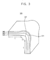
FIG. 3 illustrates a perspective view illustrating a window member in a curved display device according to example embodiments; -
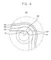
FIG. 4 illustrates a cross-sectional view illustrating an example of a portion of the window member ofFIG. 3 ; -
FIG. 5 illustrates a flow chart illustrating a method of manufacturing a window member in a curved display device according to example embodiments; -
FIGS. 6A to 6C illustrate cross-sectional views describing an example of a method of manufacturing the window member ofFIG. 5 ; -
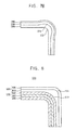
FIGS. 7A and7B illustrate cross-sectional views describing another example of a method of manufacturing the window member ofFIG. 5 ; -
FIG. 8 illustrates a cross-sectional view illustrating a portion of a curved display device according to example embodiments; and -
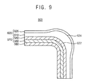
FIG. 9 illustrates a cross-sectional view illustrating a portion of a curved display device according to example embodiments. - Referring to
FIG. 1 , thewindow member 100 in the curved display device may include awindow body 120. Thewindow member 100 may further include a transparentpolymer resin layer 140 on thewindow body 120, and aprotection layer 160 disposed on the transparentpolymer resin layer 140. - The
window body 120 may protect inner portions of the display device, while passively transferring images generated by the display device (e.g., a display panel). In the curved display device, thewindow body 120 may include at least one flat portion A and at least one curved portion B. Thus, images generated by the display device may be displayed not only at the flat portion A but also at the curved portion B. - A first radius of curvature of an
inner surface 122 of the curved portion B of thewindow body 120 may be different from a second radius of curvature of anouter surface 124 of the curved portion B of thewindow body 120. - In example embodiments, the first radius of curvature of the
inner surface 122 of the curved portion B of thewindow body 120 may be greater than the second radius of curvature of anouter surface 124 of the curved portion B of thewindow body 120. For example, the first radius of curvature of theinner surface 122 may be set to about 5.8R, and the second radius of curvature of theouter surface 124 may be set to about 5R, where R represents a predetermined value or constant of a radius. Thus, thewindow body 120 may be formed such that the first radius of curvature of theinner surface 122 of the curved portion B of thewindow body 120 may be greater about 5.8/5 times than the second radius of curvature of theouter surface 124 of the curved portion B. Then, unintended refraction of light and unintended light scattering may be reduced, so that shadows of a curved display region may not appear (or, may be reduced). In example embodiments, the first radius of curvature of theinner surface 122 of the curved portion B of thewindow body 120 may be smaller than the second radius of curvature of anouter surface 124 of the curved portion B of thewindow body 120. For example, the first radius of curvature may be set to about 5R, and the second radius of curvature may be set to about 6R. - In example embodiments, a thickness of the curved portion B of the
window body 120 may be thicker than a thickness of the flat portion A of thewindow body 120. In example embodiments, the flat portion A may have substantially uniform thickness. - In example embodiments, the
window body 120 may be formed by an injection molding process that injects a melted transparent resin into a mold. The mold may be designed such that a first molding side of the mold corresponding to theinner surface 122 of the curved portion B of thewindow body 120 has a radius of curvature greater than that of a second molding side of the mold corresponding to theouter surface 124 of the curved portion B of thewindow body 120. Thus, thewindow body 120 formed by the mold such that the first radius of curvature of theinner surface 122 of the curved portion B may be greater than the second radius of curvature of theouter surface 124 of the curved portion B. In example embodiments, thewindow body 120 may include a plurality of curved portions and may have various radiuses of curvature through various shapes of the mold. For example, the second radius of curvature may be greater than the first radius of curvature (i.e., the radius of curvature of theinner surface 122 of the curved portion B may be smaller than the radius of curvature of theouter surface 124 of the curved portion B). - In example embodiments, the transparent resin included in the
window body 120 may include at least one polycarbonate (PC) or polymethylmethacrylate (PMMA). The PC and the PMMA may be stronger and more flexible than conventional glasses. Further, thewindow body 120 may be formed easily by an injection molding process using the PC or the PMMA. Thus, the PC and the PMMA may form thewindow body 120 in the curved display device. However, the transparent resin in thewindow body 120 is not limited thereto. For example, the transparent resin may include a mixed plastic material including mixed PC and PMMA. - The transparent
polymer resin layer 140 may be disposed on thewindow body 120. The transparentpolymer resin layer 140 may prevent a surface of thewindow body 120 from being damaged. In example embodiments, the transparentpolymer resin layer 140 may include at least one polyethylene-terephthalate (PET) or polyimide (PI). The transparentpolymer resin layer 140 may be attached onto thewindow body 120 as a film or a coating layer. The PET and the PI may have good strength, good electrical insulation characteristics, good durability from chemicals, low thermal contraction, and low gas permeability. Thus, physical and chemical reliability of thewindow member 100 may be improved. However, the material in the transparentpolymer resin layer 140 is not limited thereto. For example, the transparentpolymer resin layer 140 may include acrylic urethane, epoxy, polyester, etc. - In example embodiments, the
window body 120 may be attached to the transparentpolymer resin layer 140 by at least one of optically clear adhesive (OCA) or a binder. The OCA and the binder may be sprayed onto an inner surface of the transparentpolymer resin layer 140, or may be attached onto the inner surface of the transparentpolymer resin layer 140. Then, the inner surface of the transparentpolymer resin layer 140 may be attached onto an outer surface of thewindow body 120. Thus, a shape of the transparentpolymer resin layer 140 may correspond to a shape of the outer surface of thewindow body 120. A method of attaching the transparentpolymer resin layer 140 onto thewindow body 120 may be performed by a laminating process. However, the method of attaching the transparentpolymer resin layer 140 onto thewindow body 120 is not limited thereto. - The binder is a material that attaches the transparent
polymer resin layer 140 onto thewindow body 120. The binder may include an inorganic binder (e.g., epoxy, phenol, etc), an organic binder (e.g., sodium silicate, sodium calcium, etc), or a hybrid binder of the organic binder and the inorganic binder. - The
protection layer 160 may be disposed on the transparentpolymer resin layer 140 and may improve surface hardness of thewindow member 100. In example embodiments, theprotection layer 360 may include a high hardness material having hardness substantially equal to and higher than 5H. Theprotection layer 160 may include a transparent material that is a mixture of an organic material and an inorganic material. Theprotection layer 160 may be formed as a film or a coating layer on the transparentpolymer resin layer 140. For example, theprotection layer 160 may include a mixture of a glass material and a transparent polymer resin. In example embodiments, theprotection layer 160 may include an anti-reflection (coating) layer to prevent external light reflections and/or anti-fingerprint (coating) layer. However, functions of theprotection layer 160 and materials in theprotection layer 160 are not limited thereto. For example, theprotection layer 160 may be act as an antifouling layer. - As described above, the
window member 100 may include thewindow body 120 formed with the first radius of curvature different from the second radius of curvature so that shadows of a curved display region may not appear (or, may be reduced). Thus, image distortions at a curved display region may be prevented. Further, White Angular Dependency (WAD) at the side view of the display device may be improved. - In addition, when the first radius of curvature is greater than the second radius of curvature, a display panel under the inner surface of the window body may be gently bent and thus tension (or stress) applied to the display panel may be reduced.
-
FIG. 2 illustrates a cross-sectional view illustrating an example of a portion of the window member ofFIG. 1 . - Referring to
FIG. 2 , a first radius of curvature R1 of aninner surface 122 of a curved portion of awindow body 120 may be greater than a second radius of curvature R2 of anouter surface 124 of the curved portion of thewindow body 120. In example embodiments, a flat portion may have a substantially uniform thickness. Thus, a thickness of an end of the curved portion T2 of thewindow body 120 may be substantially the same as a thickness of the flat portion T3 and T4. Further, in example embodiments, a thickness of the curved portion T1 of thewindow body 120 may be thicker than a thickness of the flat portion T3 and T4 of thewindow body 120. For example, when the second radius of curvature R2 is set to about 5R, the first radius of curvature R1 may be from about 5.2R to about 6.5R, where R represents a predetermined value or constant of a radius. Thus, the thickness of the curved portion T1 of thewindow body 120 may be about 20% to about 30% thicker than the thickness of the flat portion T3 and T4 of thewindow body 120. In exemplary embodiments, shadows of the curved display region and distortions of the curved display region caused by light refracting and light scattering may not appear (or may be reduced). The thickness of the curved portion (i.e., the first radius of curvature R1 and the second radius of curvature R2) is not limited thereto. The ratio of the first radius of curvature R1 to the second radius of curvature R2 may be any ratio (or any value) that prevents shadows at the curved display region or distortions at the curved display region. Thus, the second radius of curvature R2 may be greater than the first radius of curvature R1, also. - In example embodiments, the
window body 120 may be formed by an injection molding process that injects a melted transparent resin into a mold. - The
window member 100 may further include a transparentpolymer resin layer 140 on thewindow body 120 and aprotection layer 160 on the transparentpolymer resin layer 140. As these are described above, duplicative descriptions will not be repeated. -
FIG. 3 illustrates a perspective view illustrating a window member in a curved display device according to example embodiments, andFIG. 4 illustrates a cross-sectional view illustrating an example of a portion of the window member ofFIG. 3 . Detailed descriptions on elements and/or constructions substantially the same as or similar to those illustrated with reference toFIG. 1 are omitted. - Referring to
FIGS. 3 and4 , thewindow member 300 in the curved display device may include awindow body 320. Thewindow member 300 may further include a transparent polymer resin layer 340 on thewindow body 320, and aprotection layer 360 on the transparent polymer resin layer 340. - As illustrated in
FIG. 3 , in the curved display device, thewindow body 320 may include at least one flat portion C and at least one curved portion D. Thus, images generated by the display device may be displayed not only at the flat portion C but also at the curved portion D. A first radius of curvature of aninner surface 322 of the curved portion D of thewindow body 320 may be greater than a second radius of curvature of anouter surface 324 of the curved portion D of thewindow body 320. In example embodiments, thewindow body 320 may be formed by an injection molding process that injects a melted transparent resin into a mold. Thewindow body 320 may include a plurality of curved portions and may have various radiuses of curvature through various shapes of the mold. In example embodiments, the transparent resin included in thewindow body 320 may include at least one polycarbonate (PC) or polymethylmethacrylate (PMMA). - In example embodiments, the transparent polymer resin layer 340 may be disposed on the
window body 320. The transparent polymer resin layer 340 may prevent a surface of thewindow body 320 from being damaged. In example embodiments, the transparent polymer resin layer 340 may include at least one polyethylene-terephthalate (PET) or polyimide (PI). In example embodiments, thewindow body 320 may be attached to the transparent polymer resin layer 340 by at least one of optically clear adhesive (OCA) or a binder. - The
protection layer 360 may be disposed on the transparent polymer resin layer 340 and may improve surface hardness of thewindow member 300. In example embodiments, theprotection layer 360 may include a high hardness material having hardness substantially equal to and higher than 5H. In example embodiments, theprotection layer 360 may include an anti-reflection (coating) layer to prevent external light reflections and/or anti-fingerprint (coating) layer. However, functions of theprotection layer 360 and materials in theprotection layer 360 are not limited thereto. For example, theprotection layer 360 may be act as an antifouling layer. - As illustrated in
FIG. 4 , in example embodiments, the first radius of curvature R3 of theinner surface 322 of the curved portion of thewindow body 320 may be smaller than the second radius of curvature R4 of theouter surface 324 of the curved portion of thewindow body 320. Thus, unintended refraction of light and unintended light scattering may be reduced, so that shadows of a curved display region may not appear (or, may be reduced). In example embodiments, a flat portion of thewindow body 320 may have a substantially uniform thickness. - In example embodiments, the
window body 120 having the first radius of curvature R3 and the second radius of curvature R4 may be formed by an injection molding process that injects a melted transparent resin into a mold. - The transparent resin layer 340 and the
protection layer 360 may have substantially uniform thicknesses, respectively. However, the thicknesses of the transparent resin layer 340 and theprotection layer 360 are not limited thereto. -
FIG. 5 illustrates a flow chart illustrating a method of manufacturing a window member in a curved display device according to example embodiments, andFIGS. 6A through 6C illustrate cross-sectional views describing an example of a method of manufacturing the window member ofFIG. 5 . - Referring to
FIG. 5 , the method of manufacturing the window member in the curved display device may form awindow body 120 using an injection molding process (S110), may dispose aprotection layer 160 on a transparent polymer resin layer 140 (S130), and may attach the transparentpolymer resin layer 140 onto the window body 120 (S150). - Referring to
FIGS. 5 and6A , thewindow body 120 may be formed by an injection molding process that injects a melted transparent resin into a mold, so that thewindow body 120 may include at least one flat portion and at least one curved portion (S110). The curved portion may be disposed on a curved display region of the curved display device. In example embodiments, a first radius of curvature R1 of aninner surface 122 of the curved portion may be greater than a second radius of curvature R2 of anouter surface 124 of the curved portion. The mold may be designed such that a first molding side of the mold corresponding to theinner surface 122 of the curved portion of thewindow body 120 has a radius of curvature greater than that of a second molding side of the mold corresponding to theouter surface 124 of the curved portion of thewindow body 120. Thus, thewindow body 120 formed by the mold such that the first radius of curvature of theinner surface 122 of the curved portion may be greater than the second radius of curvature of theouter surface 124 of the curved portion. Further, thewindow body 120 may include a plurality of curved portions and may have various radiuses of curvature through various shapes of the mold. In example embodiments, a thickness of the curved portion of thewindow body 120 may be thicker than a thickness of the flat portion of thewindow body 120. Further, the flat portion may have uniform thickness. As these are described above, duplicative descriptions will not be repeated. - In example embodiments, a transparent resin included in the
window body 120 may include at least one polycarbonate or polymethymethacrylate. However, the transparent resins applied to thewindow body 120 are not limited thereto. For example, the transparent resin may include a mixed plastic material including mixed PC and PMMA. - Referring to
FIGS. 5 and6B , theprotection layer 160 may be disposed on (e.g. sprayed onto) the transparent polymer resin layer 140 (or, a transparent polymer resin sheet) (S130). The transparentpolymer resin layer 140 may prevent a surface of thewindow body 120 from being damaged. In example embodiments, the transparentpolymer resin layer 140 may include at least one polyethylene-terephthalate or polyimide. However, materials applied to the transparentpolymer resin layer 140 are not limited thereto. For example, the transparentpolymer resin layer 140 may include acrylic urethane, epoxy, polyester, etc. - The
protection layer 160 may be disposed on the transparentpolymer resin layer 140 to improve surface hardness of thewindow member 100. In example embodiments, theprotection layer 160 may include a high hardness material having hardness substantially equal to and higher than 5H. Theprotection layer 160 may include a transparent material that is mixture of an organic material and an inorganic material. Theprotection layer 160 may be formed as a film or a coating layer on the transparentpolymer resin layer 140. In example embodiments, theprotection layer 160 may include an anti-reflection (coating) layer to prevent external light reflections and/or anti-fingerprint (coating) layer. However, functions of theprotection layer 160 and materials in theprotection layer 160 are not limited thereto. For example, theprotection layer 160 may be act as an antifouling layer. - In example embodiments, an attaching
material 180 may be attached to the inner surface of the transparentpolymer resin layer 140. The attachingmaterial 180 may act as attaching the transparentpolymer resin layer 140 to thewindow body 120. In example embodiments, the attaching material may include at least one of optically clear adhesive (OCA) or a binder. - Because the transparent
polymer resin layer 140 andprotection layer 160 are described above, duplicative descriptions will not be repeated. - Referring to
FIGS. 5 and6C , the transparentpolymer resin layer 140 may be attached onto the window body 120 (S150). An OCA and/or a binder may be sprayed onto an inner surface of the transparentpolymer resin layer 140, or may be attached onto the inner surface of the transparentpolymer resin layer 140. Then, the inner surface of the transparentpolymer resin layer 140 may be attached onto an outer surface of thewindow body 120. Because the transparentpolymer resin layer 140 may be flexible, the shape of the transparentpolymer resin layer 140 may correspond to the shape of the outer surface of thewindow body 120. The transparentpolymer resin layer 140 may be attached onto thewindow body 120 by a laminating process. However, the method of attaching the transparentpolymer resin layer 140 onto thewindow body 120 is not limited thereto. - As described above, the method of manufacturing the window member of the curved display device may form the
window body 120 where the first radius of curvature of the inner surface of the curved portion is greater than the second radius of curvature of the outer surface of the curved portion so that distortions of a curved display region may not appear. Further, the method of manufacturing the window member of the curved display device may form the curved portion without any additional process. -
FIGS. 7A and7B illustrate cross-sectional views describing another example of a method of manufacturing the window member ofFIG. 5 . - Referring to
FIGS. 7A and7B , the method of manufacturing the window member in the curved display device may form awindow body 320 using an injection molding process, may dispose aprotection layer 360 on a transparent polymer resin layer 340, and may attach the transparent polymer resin layer 340 onto thewindow body 120. - As illustrated in
FIG. 7A , thewindow body 320 may be formed by an injection molding process that injects a melted transparent resin into a mold, so that thewindow body 320 may include at least one flat portion and at least one curved portion. In example embodiments, a first radius of curvature R3 of aninner surface 322 of the curved portion of thewindow body 320 may be smaller than a second radius of curvature R4 of anouter surface 324 of the curved portion of thewindow body 320. The mold may be designed such that a first molding side of the mold corresponding to theinner surface 322 of the curved portion of thewindow body 320 has a radius of curvature greater than that of a second molding side of the mold corresponding to theouter surface 324 of the curved portion of thewindow body 320. Thus, thewindow body 320 formed by the mold such that the first radius of curvature of theinner surface 322 of the curved portion may be smaller than the second radius of curvature of theouter surface 324 of the curved portion. - In example embodiments, a thickness of the curved portion of the
window body 320 may be thicker than a thickness of the flat portion of thewindow body 320. Further, the flat portion may have uniform thickness. As these are described above, duplicative descriptions will not be repeated. - In example embodiments, the transparent resin included in the
window body 320 may include at least one polycarbonate (PC) or polymethylmethacrylate (PMMA). However, the transparent resin in thewindow body 120 is not limited thereto. - As illustrated in
FIG. 7B , the transparent polymer resin layer 340 may be attached onto thewindow body 320. Theprotection layer 360 may be formed on the transparent polymer resin layer 340. An OCA and/or a binder may be sprayed onto an inner surface of the transparent polymer resin layer 340, or may be attached onto the inner surface of the transparent polymer resin layer 340. Then, the inner surface of the transparent polymer resin layer 340 may be attached onto an outer surface of thewindow body 320. Because the transparent polymer resin layer 340 may be flexible, the shape of the transparent polymer resin layer 340 may correspond to the shape of the outer surface of thewindow body 320. Radiuses of curvature of inner surfaces of curved portions of the transparent polymer resin layer 340 and theprotection layer 360 may be smaller than radiuses of curvature of outer surfaces of curved portions of the transparent polymer resin layer 340 and theprotection layer 360, respectively. -
FIG. 8 illustrates a cross-sectional view illustrating a portion of a curved display device according to example embodiments. - Referring to
FIG. 8 , thecurved display device 500 may include adisplay panel 580 including at least one curved display region, afunctional panel 570, and awindow member 520. - The
display panel 580 may include a plurality of pixels including a plurality of pixel circuits. Thedisplay panel 580 may include a scan driving unit, a data driving unit, a power unit, and a timing control unit to display images. Further, thedisplay panel 580 may include a flexible substrate for designing thecurved display device 500. - The
functional panel 570 may be disposed on thedisplay panel 580. In example embodiments, thefunctional panel 570 may include at least one of a protection film, a polarizing plate, and a touch screen panel. Because these are examples, the functional panels and locations of the functional panels are not limited thereto. Any panel (or, plate) may be included in thefunctional panel 570 to provide various functions to thecurved display device 500. Thefunctional panel 570 may include a flexible substrate to design thecurved display device 500. Thefunctional panel 570 may be attached onto thedisplay panel 570 by OCA, binder, etc. - The
window member 520 may be disposed on thefunctional panel 570. Thewindow member 520 may include awindow body 510 that includes a curved portion corresponding to the curved display region of thecurved display device 500 and a flat portion. Thewindow member 520 may protect inner panels (i.e., the display panel and the functional panel) of thecurved display device 500 from external factors. - In example embodiments, the
window member 520 may further include a transparentpolymer resin layer 505 disposed on thewindow body 510, and a protection layer (not illustrated) disposed on the transparentpolymer resin layer 505. - A first radius of curvature of
inner surface 522 of the curved portion of thewindow body 510 may be different from a second radius of curvature ofouter surface 524 of the curved portion of thewindow body 510. In example embodiments, the first radius of curvature may be greater than the second radius of curvature. Thus, unintended refraction of light and unintended light scattering may be reduced, so that shadows of a curved display region may not appear (or, may be reduced). In example embodiments, a thickness of the curved portion of the window body 501 may be thicker than a thickness of the flat portion of the window body because of difference between the first radius of curvature and the second radius of curvature. The flat portion may have uniform thickness. In example embodiments, the window body may be formed by an injection molding process that injects a melted transparent resin into a mold. As these are described above, duplicated descriptions will not be repeated. - In example embodiments, the transparent resin included in the
window body 510 may include at least one polycarbonate or polymethylmethacrylate. In example embodiments, the transparentpolymer resin layer 505 may include at least one polyethylene-terephthalate or polyimide. The protection layer may be disposed on (e.g. sprayed onto) the transparentpolymer resin layer 505. The protection layer may include a mixture of a glass material and a transparent polymer resin. The protection layer may be formed as a film or a coating layer on the transparentpolymer resin layer 505. As these are described above, duplicative descriptions will not be repeated. - As described above, the
window body 510 of thewindow member 520 in thecurved display device 500 may include the curved portion that the first radius of curvature of theinner surface 522 of the curved portion is greater than a second radius of curvature of anouter surface 524 of the curved portion. Thus, distortions and shadows of the curved display region may be reduced (or, may not appear), so that visibility of thecurved display device 500 may be improved. - In addition, the display panel under the inner surface of the window body may be gently bent, and thus tension (or stress) applied to the display panel may be reduced.
-
FIG. 9 illustrates a cross-sectional view illustrating a portion of a curved display device according to example embodiments. - Referring to
FIG. 9 , thecurved display device 600 may include adisplay panel 580 including at least one curved display region, afunctional panel 570, and awindow member 620. InFIG. 9 , like reference numerals are used to designate elements the same as those inFIG. 8 , and detailed description of these elements may be omitted. Thecurved display device 600 ofFIG. 9 may be substantially the same as or similar to thecurved display device 500 ofFIG. 8 except for the shape a curved portion of thewindow member 620. - The
window member 620 may be disposed on thefunctional panel 570. Thewindow member 620 may include a window body 610 that includes a curved portion corresponding to the curved display region of thecurved display device 600 and a flat portion. Thewindow member 620 may protect inner panels (i.e., the display panel and the functional panel) of thecurved display device 600 from external factors. - In example embodiments, the
window member 620 may further include a transparentpolymer resin layer 605 disposed on the window body 610, and a protection layer (not illustrated) disposed on the transparentpolymer resin layer 605. - In example embodiments, a first radius of curvature of
inner surface 622 of the curved portion of the window body 610 may be different from a second radius of curvature ofouter surface 624 of the curved portion of the window body 610. Thus, unintended refraction of light and unintended light scattering may be reduced, so that shadows of a curved display region may not appear (or, may be reduced). - In example embodiments, a transparent resin included in the window body 610 may include at least one PC or PMMA. In example embodiments, the transparent
polymer resin layer 605 may include at least one PET or PI. - The protection layer may be formed on (or, sprayed onto) the transparent
polymer resin layer 605. The protection layer may include a mixture of a glass material and a transparent polymer resin. The protection layer may be formed as a film or a coating layer on the transparentpolymer resin layer 605. As these are described above, duplicative descriptions will not be repeated. - As described above, the window body 610 of the
window member 620 in thecurved display device 600 may include the curved portion that the first radius of curvature of theinner surface 622 of the curved portion is smaller than a second radius of curvature of anouter surface 624 of the curved portion. Thus, distortions and shadows of the curved display region may be reduced (or, may not appear), so that visibility of thecurved display device 600 may be improved. - The present embodiments may be applied to any curved display device, and to any electronic device including the curved display device. For example, the present embodiments may be applied to a television, a digital television, a three-dimensional television, a mobile phone, a smart phone, a laptop computer, a tablet computer, a personal digital assistants (PDA), a portable multimedia player (PMP), a digital camera, a music player, a portable game console, a navigation device, etc.
- By way of summation and review, curved or flexible display devices may be thin, light, bendable, and more shock-resistant than flat panel display devices. Further, curved (or flexible) display devices can be designed in various shapes. In a curved display device, a window member may have the same thickness at a curved portion as at a flat portion. In this case, a shadow may be caused by the refraction of light at the curved display region according to an angle at which a user views the curved display device, and may result in image distortion.
- In contrast, example embodiments provide a window member capable of preventing or reducing an image distortion at a curved portion.
- A window member in a curved display device according to example embodiments may have a window body that is formed such that a radius of curvature of an inner surface of a curved portion of the window body is different from a radius of curvature of an outer surface of the curved portion of the window body, so that shadows of a curved display region may not appear or may be reduced.
- Furthermore, a curved display device according to example embodiments may include the window member that has the first radius of curvature being greater than the second radius of curvature, so that image distortions at a curved display region may be prevented. A display panel under the inner surface of the window body may be more gently bent than other display panels, and thus tension or stress applied to the display panel may be reduced.
- Example embodiments have been disclosed herein, and although specific terms are employed, they are used and are to be interpreted in a generic and descriptive sense only and not for purpose of limitation. In some instances, as would be apparent to one of ordinary skill in the art as of the filing of the present application, features, characteristics, and/or elements described in connection with a particular embodiment may be used singly or in combination with features, characteristics, and/or elements described in connection with other embodiments unless otherwise specifically indicated. Accordingly, it will be understood by those of skill in the art that various changes in form and details may be made without departing from the scope of the present invention as set forth in the following claims.
Claims (13)
- A window member for a curved display device, comprising:a window body including a flat portion and a curved portion,wherein a first radius of curvature of an inner surface of the curved portion is different from a second radius of curvature of an outer surface of the curved portion.
- The window member as claimed in claim 1, wherein the first radius of curvature is greater than the second radius of curvature.
- The window member as claimed in claim 1, wherein the first radius of curvature is smaller than the second radius of curvature.
- The window member as claimed in claim 1, 2 or 3, wherein the curved portion of the window body is thicker than the flat portion of the window body.
- The window member as claimed in claim 4, wherein the window body is formed by an injection molding process that injects a melted transparent resin into a mold.
- The window member as claimed in claim 5, wherein the transparent resin includes at least one of polycarbonate (PC) or polymethylmethacrylate (PMMA).
- The window member as claimed in any one of the preceding claims, further comprising:a transparent polymer resin layer disposed on the window body; anda protection layer disposed on the transparent polymer resin layer.
- The window member as claimed in claim 7, wherein the transparent polymer resin layer includes at least one of polyethylene-terephthalate (PET) or polyimide (PI).
- The window member as claimed in claim 7, wherein the window body is attached to the transparent polymer resin layer by at least one of optically clear adhesive OCA or binder.
- The window member as claimed in claim 7, 8 or 9, wherein the protection layer includes an anti-reflection layer or an anti-fingerprint layer.
- A curved display device comprising:a display panel including a curved display region;a functional panel on the display panel; anda window member according to any one of the preceding claims on the functional panel, wherein the curved portion of the window body corresponds to the curved display region of the display panel.
- A method of manufacturing a window member for a curved display device, the method comprising:forming a window body having a flat portion and a curved portion by injecting a melted transparent resin into a mold;disposing a protection layer on a transparent polymer resin layer; andattaching the transparent polymer resin layer onto the window body,wherein a first radius of curvature of an inner surface of the curved portion is different from a second radius of curvature of an outer surface of the curved portion.
- The method as claimed in claim 12, wherein the first radius of curvature is greater than the second radius of curvature, and
wherein a thickness of the curved portion of the window body is thicker than a thickness of the flat portion of the window body.
Applications Claiming Priority (2)
| Application Number | Priority Date | Filing Date | Title |
|---|---|---|---|
| KR20130120244 | 2013-10-10 | ||
| KR1020140052247A KR101669026B1 (en) | 2013-10-10 | 2014-04-30 | Window member in a bended display device, method of manufacturing a window member of a bended display device, and bended display device having the same |
Publications (2)
| Publication Number | Publication Date |
|---|---|
| EP2860025A1 true EP2860025A1 (en) | 2015-04-15 |
| EP2860025B1 EP2860025B1 (en) | 2016-11-02 |
Family
ID=51618968
Family Applications (1)
| Application Number | Title | Priority Date | Filing Date |
|---|---|---|---|
| EP14183961.3A Active EP2860025B1 (en) | 2013-10-10 | 2014-09-08 | Window member in a curved display device, method of manufacturing a window member of a curved display device, and curved display device having the same |
Country Status (3)
| Country | Link |
|---|---|
| US (1) | US9572267B2 (en) |
| EP (1) | EP2860025B1 (en) |
| JP (1) | JP6607666B2 (en) |
Cited By (2)
| Publication number | Priority date | Publication date | Assignee | Title |
|---|---|---|---|---|
| CN107358873A (en) * | 2016-05-10 | 2017-11-17 | 三星显示有限公司 | Rollable display device |
| EP3598857A1 (en) * | 2015-08-11 | 2020-01-22 | Samsung Electronics Co., Ltd. | Method for manufacturing exterior housing and electronic device comprising same |
Families Citing this family (25)
| Publication number | Priority date | Publication date | Assignee | Title |
|---|---|---|---|---|
| US9295297B2 (en) | 2014-06-17 | 2016-03-29 | Racing Optics, Inc. | Adhesive mountable stack of removable layers |
| KR102392671B1 (en) * | 2015-05-11 | 2022-04-29 | 삼성디스플레이 주식회사 | Flexible display |
| KR102603654B1 (en) * | 2016-08-24 | 2023-11-17 | 삼성디스플레이 주식회사 | Display device |
| KR102723083B1 (en) * | 2017-01-17 | 2024-10-29 | 세키스이가가쿠 고교가부시키가이샤 | Filling-bonding material, protective sheet-equipped filling-bonding material, laminated body, optical device, and protective panel for optical device |
| KR102367971B1 (en) * | 2017-06-16 | 2022-02-25 | 삼성디스플레이 주식회사 | Cover window and display device comprising the same |
| JP7029894B2 (en) * | 2017-07-11 | 2022-03-04 | 株式会社ジャパンディスプレイ | Display device |
| KR102393175B1 (en) * | 2017-09-25 | 2022-05-02 | 엘지전자 주식회사 | Display device |
| KR102450111B1 (en) * | 2017-12-28 | 2022-10-05 | 삼성디스플레이 주식회사 | Display device |
| KR20190090522A (en) * | 2018-01-25 | 2019-08-02 | 엘지전자 주식회사 | Mobile terminal |
| US11737307B1 (en) * | 2018-06-05 | 2023-08-22 | Apple Inc. | Electronic devices having curved displays with supporting frames |
| KR102494409B1 (en) * | 2018-07-10 | 2023-02-01 | 삼성디스플레이 주식회사 | Display device |
| US11846788B2 (en) | 2019-02-01 | 2023-12-19 | Racing Optics, Inc. | Thermoform windshield stack with integrated formable mold |
| US11364715B2 (en) * | 2019-05-21 | 2022-06-21 | Racing Optics, Inc. | Polymer safety glazing for vehicles |
| KR102663520B1 (en) * | 2019-08-23 | 2024-05-08 | 삼성디스플레이 주식회사 | Cover window and display apparatus having the same |
| US11912001B2 (en) | 2019-12-03 | 2024-02-27 | Ro Technologies, Llc | Method and apparatus for reducing non-normal incidence distortion in glazing films |
| US11648723B2 (en) | 2019-12-03 | 2023-05-16 | Racing Optics, Inc. | Method and apparatus for reducing non-normal incidence distortion in glazing films |
| US11548356B2 (en) | 2020-03-10 | 2023-01-10 | Racing Optics, Inc. | Protective barrier for safety glazing |
| US20210285661A1 (en) | 2020-03-10 | 2021-09-16 | Wolf Steel Ltd. | Heating and cooling appliance |
| KR102774689B1 (en) | 2020-05-26 | 2025-03-06 | 삼성디스플레이 주식회사 | Foldable display device |
| KR102905385B1 (en) | 2020-11-18 | 2025-12-30 | 삼성전자주식회사 | Foldable electronic device including flexible display |
| US11490667B1 (en) | 2021-06-08 | 2022-11-08 | Racing Optics, Inc. | Low haze UV blocking removable lens stack |
| US11709296B2 (en) | 2021-07-27 | 2023-07-25 | Racing Optics, Inc. | Low reflectance removable lens stack |
| US12140781B2 (en) | 2021-07-27 | 2024-11-12 | Laminated Film Llc | Low reflectance removable lens stack |
| US11933943B2 (en) | 2022-06-06 | 2024-03-19 | Laminated Film Llc | Stack of sterile peelable lenses with low creep |
| CN117711269B (en) * | 2023-12-27 | 2025-02-11 | 武汉华星光电半导体显示技术有限公司 | Display module and display device |
Citations (3)
| Publication number | Priority date | Publication date | Assignee | Title |
|---|---|---|---|---|
| EP1327510A1 (en) * | 2000-10-17 | 2003-07-16 | Nissha Printing Co., Ltd. | Antireflective formed article and method for preparation thereof, and mold for antireflective formed article |
| EP1914067A2 (en) * | 2005-11-08 | 2008-04-23 | Fujitsu Component Limited | Method for fabricating a curved casing formed from thermoplastic resin and film having a polarizing effect |
| US20130000822A1 (en) * | 2011-06-28 | 2013-01-03 | Samsung Electronics Co., Ltd. | Method for fabricating a window member of the display device of a portable terminal |
Family Cites Families (33)
| Publication number | Priority date | Publication date | Assignee | Title |
|---|---|---|---|---|
| KR200328691Y1 (en) | 2003-05-26 | 2003-10-01 | (주)씨엠케이 | structure to improve visibility of LCD protector |
| DE112005002886T5 (en) * | 2004-11-26 | 2007-10-11 | Mitsui Chemicals, Inc. | Window material for display |
| TWI259715B (en) | 2005-01-25 | 2006-08-01 | Wistron Corp | Electronic device able to adjust the size of the display area |
| TW200627124A (en) | 2005-01-25 | 2006-08-01 | Wistron Corp | Electronic Device with Continuously Adjustable Size of Display Area |
| JP2007190794A (en) | 2006-01-19 | 2007-08-02 | Sumitomo Chemical Co Ltd | Display window protection plate for portable information terminals |
| JP2007326259A (en) * | 2006-06-07 | 2007-12-20 | Yoshida Industry Co Ltd | Display manufacturing method and display |
| JP5305631B2 (en) * | 2007-10-25 | 2013-10-02 | 出光興産株式会社 | Polycarbonate resin composition, polycarbonate resin molded article and method for producing the same |
| KR100994102B1 (en) | 2008-11-28 | 2010-11-15 | (주) 태양기전 | Display Protection Windows for Notebooks |
| KR20090010012A (en) | 2008-12-18 | 2009-01-28 | 주식회사 삼광 | Manufacturing method of mobile phone window |
| US8911653B2 (en) * | 2009-05-21 | 2014-12-16 | Semiconductor Energy Laboratory Co., Ltd. | Method for manufacturing light-emitting device |
| KR101084152B1 (en) * | 2009-07-23 | 2011-11-17 | 엘지전자 주식회사 | Display device |
| KR101113289B1 (en) | 2010-03-04 | 2012-02-24 | 주식회사 토비스 | Method for forming display panel with curved shape, display panel with curved shape using the method, and multi-layer image display device using the display panel |
| KR101113457B1 (en) | 2010-05-10 | 2012-03-05 | 삼성모바일디스플레이주식회사 | Curved Touch Screen Panel and Fabricating Method for the Same |
| KR101211371B1 (en) * | 2010-09-16 | 2012-12-13 | 주식회사 토비스 | Method for manufacturing display panel with curved shape |
| KR20120116813A (en) | 2011-04-13 | 2012-10-23 | 엘지이노텍 주식회사 | Flexible display device and method of manufacturing the same |
| US20120288661A1 (en) * | 2011-05-10 | 2012-11-15 | Weis Limited | Solid structure glass and method for making the same |
| JP2013003306A (en) | 2011-06-15 | 2013-01-07 | Sony Corp | Display and electronic apparatus |
| US10061356B2 (en) | 2011-06-30 | 2018-08-28 | Samsung Display Co., Ltd. | Flexible display panel and display apparatus including the flexible display panel |
| KR101320385B1 (en) | 2011-06-30 | 2013-10-23 | 삼성디스플레이 주식회사 | Flexible display panel and the display apparatus comprising the flexible display panel |
| KR101320384B1 (en) * | 2011-06-30 | 2013-10-23 | 삼성디스플레이 주식회사 | Flexible display panel and the display apparatus comprising the flexible display panel |
| KR20130015230A (en) * | 2011-08-02 | 2013-02-13 | 삼성디스플레이 주식회사 | Display device and method for manufacturing the same |
| KR101837714B1 (en) | 2011-08-10 | 2018-03-13 | 삼성디스플레이 주식회사 | Display device |
| US20130080932A1 (en) | 2011-09-27 | 2013-03-28 | Sanjiv Sirpal | Secondary single screen mode activation through user interface toggle |
| JP5630428B2 (en) * | 2011-12-12 | 2014-11-26 | コニカミノルタ株式会社 | Cover glass for display |
| JP5712912B2 (en) * | 2011-12-14 | 2015-05-07 | コニカミノルタ株式会社 | Cover glass for display |
| KR101268471B1 (en) | 2011-12-20 | 2013-06-04 | 주식회사 토비스 | Method for forming display panel with curved shape, display panel with curved shape using the method, and multi-layer image display device using the display panel |
| KR20130091225A (en) * | 2012-02-07 | 2013-08-16 | 주식회사 에스앤에스텍 | Functional module and methods for fabricating the same |
| JP2013200495A (en) * | 2012-03-26 | 2013-10-03 | Dainippon Printing Co Ltd | Array type display device |
| KR101386219B1 (en) * | 2012-06-26 | 2014-04-17 | 삼성디스플레이 주식회사 | Flexible display panel, display device comprising the panel and method thereof |
| KR20140002470A (en) * | 2012-06-29 | 2014-01-08 | 삼성디스플레이 주식회사 | Display device, manufacturing method of the same and manufacturing device of the same |
| KR102114312B1 (en) * | 2012-10-29 | 2020-06-18 | 삼성디스플레이 주식회사 | Display Device and method for controlling display image |
| KR101991839B1 (en) * | 2013-01-15 | 2019-06-24 | 삼성디스플레이 주식회사 | Display device having cover window |
| KR101975490B1 (en) | 2013-02-18 | 2019-05-08 | 삼성디스플레이 주식회사 | Cover window and display device with the cover window |
-
2014
- 2014-08-27 JP JP2014172452A patent/JP6607666B2/en active Active
- 2014-09-08 EP EP14183961.3A patent/EP2860025B1/en active Active
- 2014-09-23 US US14/493,854 patent/US9572267B2/en active Active
Patent Citations (3)
| Publication number | Priority date | Publication date | Assignee | Title |
|---|---|---|---|---|
| EP1327510A1 (en) * | 2000-10-17 | 2003-07-16 | Nissha Printing Co., Ltd. | Antireflective formed article and method for preparation thereof, and mold for antireflective formed article |
| EP1914067A2 (en) * | 2005-11-08 | 2008-04-23 | Fujitsu Component Limited | Method for fabricating a curved casing formed from thermoplastic resin and film having a polarizing effect |
| US20130000822A1 (en) * | 2011-06-28 | 2013-01-03 | Samsung Electronics Co., Ltd. | Method for fabricating a window member of the display device of a portable terminal |
Cited By (6)
| Publication number | Priority date | Publication date | Assignee | Title |
|---|---|---|---|---|
| EP3598857A1 (en) * | 2015-08-11 | 2020-01-22 | Samsung Electronics Co., Ltd. | Method for manufacturing exterior housing and electronic device comprising same |
| US10750629B2 (en) | 2015-08-11 | 2020-08-18 | Samsung Electronics Co., Ltd. | Method for manufacturing exterior housing and electronic device comprising same |
| US11516930B2 (en) | 2015-08-11 | 2022-11-29 | Samsung Electronics Co., Ltd. | Method for manufacturing exterior housing and electronic device comprising same |
| US11805611B2 (en) | 2015-08-11 | 2023-10-31 | Samsung Electronics Co., Ltd. | Method for manufacturing exterior housing and electronic device comprising same |
| US12349297B2 (en) | 2015-08-11 | 2025-07-01 | Samsung Electronics Co., Ltd | Method for manufacturing exterior housing and electronic device comprising same |
| CN107358873A (en) * | 2016-05-10 | 2017-11-17 | 三星显示有限公司 | Rollable display device |
Also Published As
| Publication number | Publication date |
|---|---|
| JP2015075760A (en) | 2015-04-20 |
| JP6607666B2 (en) | 2019-11-20 |
| US20150103474A1 (en) | 2015-04-16 |
| US9572267B2 (en) | 2017-02-14 |
| EP2860025B1 (en) | 2016-11-02 |
Similar Documents
| Publication | Publication Date | Title |
|---|---|---|
| EP2860025B1 (en) | Window member in a curved display device, method of manufacturing a window member of a curved display device, and curved display device having the same | |
| CN104553184B (en) | Bend window member, its manufacture method and the bending display device in display device | |
| US10586944B2 (en) | Display device having window member and method of manufacturing window member | |
| US10852768B2 (en) | Display device | |
| US10510816B2 (en) | Display device and manufacturing method thereof | |
| US10003044B2 (en) | Cover window for a display device, and a display device including the same | |
| US8659503B2 (en) | Multi-display apparatus having overlapping display panels | |
| KR102281847B1 (en) | Flexible display device | |
| US11820043B2 (en) | Display device and method of manufacturing cover member | |
| US20150004334A1 (en) | Foldable transparent composite cover window, manufacturing method of the same, and foldable display device containing the same | |
| US10470319B2 (en) | Window and a display apparatus including the same | |
| KR101954233B1 (en) | Touch panel with the excellent visibility and manufacturing method thereof | |
| US8593372B2 (en) | Foldable display device | |
| CN208271483U (en) | A kind of display device | |
| US20150024170A1 (en) | Window member and image display apparatus including the same | |
| US9949397B2 (en) | Touch panel having improved visibility and method of manufacturing the same | |
| CN114078379A (en) | Display device and method for manufacturing display device | |
| US20140354907A1 (en) | Composite touch cover plate | |
| US20190011605A1 (en) | Glass member for display device, method of fabricating the glass member, and display device including the glass member | |
| CN106843388A (en) | Display screen component and its assemble method and electronic installation | |
| CN111462624A (en) | Protective member, display device, and method for manufacturing a protective member | |
| CN112820200A (en) | Cover plate and display device | |
| CN222232826U (en) | Screen modules and electronic devices | |
| US9477264B2 (en) | Window member for display screen of portable terminal and method for fabricating the window member | |
| KR20120091784A (en) | Display device for portable communication device |
Legal Events
| Date | Code | Title | Description |
|---|---|---|---|
| PUAI | Public reference made under article 153(3) epc to a published international application that has entered the european phase |
Free format text: ORIGINAL CODE: 0009012 |
|
| 17P | Request for examination filed |
Effective date: 20140908 |
|
| AK | Designated contracting states |
Kind code of ref document: A1 Designated state(s): AL AT BE BG CH CY CZ DE DK EE ES FI FR GB GR HR HU IE IS IT LI LT LU LV MC MK MT NL NO PL PT RO RS SE SI SK SM TR |
|
| AX | Request for extension of the european patent |
Extension state: BA ME |
|
| R17P | Request for examination filed (corrected) |
Effective date: 20150624 |
|
| RBV | Designated contracting states (corrected) |
Designated state(s): AL AT BE BG CH CY CZ DE DK EE ES FI FR GB GR HR HU IE IS IT LI LT LU LV MC MK MT NL NO PL PT RO RS SE SI SK SM TR |
|
| RAP1 | Party data changed (applicant data changed or rights of an application transferred) |
Owner name: SAMSUNG DISPLAY CO., LTD. |
|
| GRAP | Despatch of communication of intention to grant a patent |
Free format text: ORIGINAL CODE: EPIDOSNIGR1 |
|
| INTG | Intention to grant announced |
Effective date: 20160524 |
|
| GRAS | Grant fee paid |
Free format text: ORIGINAL CODE: EPIDOSNIGR3 |
|
| GRAA | (expected) grant |
Free format text: ORIGINAL CODE: 0009210 |
|
| AK | Designated contracting states |
Kind code of ref document: B1 Designated state(s): AL AT BE BG CH CY CZ DE DK EE ES FI FR GB GR HR HU IE IS IT LI LT LU LV MC MK MT NL NO PL PT RO RS SE SI SK SM TR |
|
| REG | Reference to a national code |
Ref country code: GB Ref legal event code: FG4D |
|
| REG | Reference to a national code |
Ref country code: AT Ref legal event code: REF Ref document number: 841404 Country of ref document: AT Kind code of ref document: T Effective date: 20161115 Ref country code: CH Ref legal event code: EP |
|
| REG | Reference to a national code |
Ref country code: IE Ref legal event code: FG4D |
|
| REG | Reference to a national code |
Ref country code: DE Ref legal event code: R096 Ref document number: 602014004590 Country of ref document: DE |
|
| PG25 | Lapsed in a contracting state [announced via postgrant information from national office to epo] |
Ref country code: LV Free format text: LAPSE BECAUSE OF FAILURE TO SUBMIT A TRANSLATION OF THE DESCRIPTION OR TO PAY THE FEE WITHIN THE PRESCRIBED TIME-LIMIT Effective date: 20161102 |
|
| REG | Reference to a national code |
Ref country code: NL Ref legal event code: MP Effective date: 20161102 |
|
| REG | Reference to a national code |
Ref country code: LT Ref legal event code: MG4D |
|
| REG | Reference to a national code |
Ref country code: AT Ref legal event code: MK05 Ref document number: 841404 Country of ref document: AT Kind code of ref document: T Effective date: 20161102 |
|
| PG25 | Lapsed in a contracting state [announced via postgrant information from national office to epo] |
Ref country code: SE Free format text: LAPSE BECAUSE OF FAILURE TO SUBMIT A TRANSLATION OF THE DESCRIPTION OR TO PAY THE FEE WITHIN THE PRESCRIBED TIME-LIMIT Effective date: 20161102 Ref country code: LT Free format text: LAPSE BECAUSE OF FAILURE TO SUBMIT A TRANSLATION OF THE DESCRIPTION OR TO PAY THE FEE WITHIN THE PRESCRIBED TIME-LIMIT Effective date: 20161102 Ref country code: NL Free format text: LAPSE BECAUSE OF FAILURE TO SUBMIT A TRANSLATION OF THE DESCRIPTION OR TO PAY THE FEE WITHIN THE PRESCRIBED TIME-LIMIT Effective date: 20161102 Ref country code: NO Free format text: LAPSE BECAUSE OF FAILURE TO SUBMIT A TRANSLATION OF THE DESCRIPTION OR TO PAY THE FEE WITHIN THE PRESCRIBED TIME-LIMIT Effective date: 20170202 Ref country code: GR Free format text: LAPSE BECAUSE OF FAILURE TO SUBMIT A TRANSLATION OF THE DESCRIPTION OR TO PAY THE FEE WITHIN THE PRESCRIBED TIME-LIMIT Effective date: 20170203 |
|
| PG25 | Lapsed in a contracting state [announced via postgrant information from national office to epo] |
Ref country code: FI Free format text: LAPSE BECAUSE OF FAILURE TO SUBMIT A TRANSLATION OF THE DESCRIPTION OR TO PAY THE FEE WITHIN THE PRESCRIBED TIME-LIMIT Effective date: 20161102 Ref country code: PL Free format text: LAPSE BECAUSE OF FAILURE TO SUBMIT A TRANSLATION OF THE DESCRIPTION OR TO PAY THE FEE WITHIN THE PRESCRIBED TIME-LIMIT Effective date: 20161102 Ref country code: IS Free format text: LAPSE BECAUSE OF FAILURE TO SUBMIT A TRANSLATION OF THE DESCRIPTION OR TO PAY THE FEE WITHIN THE PRESCRIBED TIME-LIMIT Effective date: 20170302 Ref country code: PT Free format text: LAPSE BECAUSE OF FAILURE TO SUBMIT A TRANSLATION OF THE DESCRIPTION OR TO PAY THE FEE WITHIN THE PRESCRIBED TIME-LIMIT Effective date: 20170302 Ref country code: RS Free format text: LAPSE BECAUSE OF FAILURE TO SUBMIT A TRANSLATION OF THE DESCRIPTION OR TO PAY THE FEE WITHIN THE PRESCRIBED TIME-LIMIT Effective date: 20161102 Ref country code: AT Free format text: LAPSE BECAUSE OF FAILURE TO SUBMIT A TRANSLATION OF THE DESCRIPTION OR TO PAY THE FEE WITHIN THE PRESCRIBED TIME-LIMIT Effective date: 20161102 Ref country code: ES Free format text: LAPSE BECAUSE OF FAILURE TO SUBMIT A TRANSLATION OF THE DESCRIPTION OR TO PAY THE FEE WITHIN THE PRESCRIBED TIME-LIMIT Effective date: 20161102 Ref country code: HR Free format text: LAPSE BECAUSE OF FAILURE TO SUBMIT A TRANSLATION OF THE DESCRIPTION OR TO PAY THE FEE WITHIN THE PRESCRIBED TIME-LIMIT Effective date: 20161102 |
|
| PG25 | Lapsed in a contracting state [announced via postgrant information from national office to epo] |
Ref country code: SK Free format text: LAPSE BECAUSE OF FAILURE TO SUBMIT A TRANSLATION OF THE DESCRIPTION OR TO PAY THE FEE WITHIN THE PRESCRIBED TIME-LIMIT Effective date: 20161102 Ref country code: RO Free format text: LAPSE BECAUSE OF FAILURE TO SUBMIT A TRANSLATION OF THE DESCRIPTION OR TO PAY THE FEE WITHIN THE PRESCRIBED TIME-LIMIT Effective date: 20161102 Ref country code: CZ Free format text: LAPSE BECAUSE OF FAILURE TO SUBMIT A TRANSLATION OF THE DESCRIPTION OR TO PAY THE FEE WITHIN THE PRESCRIBED TIME-LIMIT Effective date: 20161102 Ref country code: EE Free format text: LAPSE BECAUSE OF FAILURE TO SUBMIT A TRANSLATION OF THE DESCRIPTION OR TO PAY THE FEE WITHIN THE PRESCRIBED TIME-LIMIT Effective date: 20161102 Ref country code: DK Free format text: LAPSE BECAUSE OF FAILURE TO SUBMIT A TRANSLATION OF THE DESCRIPTION OR TO PAY THE FEE WITHIN THE PRESCRIBED TIME-LIMIT Effective date: 20161102 |
|
| REG | Reference to a national code |
Ref country code: DE Ref legal event code: R097 Ref document number: 602014004590 Country of ref document: DE |
|
| REG | Reference to a national code |
Ref country code: FR Ref legal event code: PLFP Year of fee payment: 4 |
|
| PG25 | Lapsed in a contracting state [announced via postgrant information from national office to epo] |
Ref country code: BG Free format text: LAPSE BECAUSE OF FAILURE TO SUBMIT A TRANSLATION OF THE DESCRIPTION OR TO PAY THE FEE WITHIN THE PRESCRIBED TIME-LIMIT Effective date: 20170202 Ref country code: SM Free format text: LAPSE BECAUSE OF FAILURE TO SUBMIT A TRANSLATION OF THE DESCRIPTION OR TO PAY THE FEE WITHIN THE PRESCRIBED TIME-LIMIT Effective date: 20161102 Ref country code: IT Free format text: LAPSE BECAUSE OF FAILURE TO SUBMIT A TRANSLATION OF THE DESCRIPTION OR TO PAY THE FEE WITHIN THE PRESCRIBED TIME-LIMIT Effective date: 20161102 Ref country code: BE Free format text: LAPSE BECAUSE OF FAILURE TO SUBMIT A TRANSLATION OF THE DESCRIPTION OR TO PAY THE FEE WITHIN THE PRESCRIBED TIME-LIMIT Effective date: 20161102 |
|
| PLBE | No opposition filed within time limit |
Free format text: ORIGINAL CODE: 0009261 |
|
| STAA | Information on the status of an ep patent application or granted ep patent |
Free format text: STATUS: NO OPPOSITION FILED WITHIN TIME LIMIT |
|
| 26N | No opposition filed |
Effective date: 20170803 |
|
| PG25 | Lapsed in a contracting state [announced via postgrant information from national office to epo] |
Ref country code: SI Free format text: LAPSE BECAUSE OF FAILURE TO SUBMIT A TRANSLATION OF THE DESCRIPTION OR TO PAY THE FEE WITHIN THE PRESCRIBED TIME-LIMIT Effective date: 20161102 |
|
| REG | Reference to a national code |
Ref country code: CH Ref legal event code: PL |
|
| PG25 | Lapsed in a contracting state [announced via postgrant information from national office to epo] |
Ref country code: MC Free format text: LAPSE BECAUSE OF FAILURE TO SUBMIT A TRANSLATION OF THE DESCRIPTION OR TO PAY THE FEE WITHIN THE PRESCRIBED TIME-LIMIT Effective date: 20161102 |
|
| REG | Reference to a national code |
Ref country code: IE Ref legal event code: MM4A |
|
| PG25 | Lapsed in a contracting state [announced via postgrant information from national office to epo] |
Ref country code: LU Free format text: LAPSE BECAUSE OF NON-PAYMENT OF DUE FEES Effective date: 20170908 |
|
| PG25 | Lapsed in a contracting state [announced via postgrant information from national office to epo] |
Ref country code: IE Free format text: LAPSE BECAUSE OF NON-PAYMENT OF DUE FEES Effective date: 20170908 Ref country code: LI Free format text: LAPSE BECAUSE OF NON-PAYMENT OF DUE FEES Effective date: 20170930 Ref country code: CH Free format text: LAPSE BECAUSE OF NON-PAYMENT OF DUE FEES Effective date: 20170930 |
|
| REG | Reference to a national code |
Ref country code: FR Ref legal event code: PLFP Year of fee payment: 5 |
|
| PG25 | Lapsed in a contracting state [announced via postgrant information from national office to epo] |
Ref country code: MT Free format text: LAPSE BECAUSE OF NON-PAYMENT OF DUE FEES Effective date: 20170908 |
|
| PG25 | Lapsed in a contracting state [announced via postgrant information from national office to epo] |
Ref country code: HU Free format text: LAPSE BECAUSE OF FAILURE TO SUBMIT A TRANSLATION OF THE DESCRIPTION OR TO PAY THE FEE WITHIN THE PRESCRIBED TIME-LIMIT; INVALID AB INITIO Effective date: 20140908 |
|
| PG25 | Lapsed in a contracting state [announced via postgrant information from national office to epo] |
Ref country code: CY Free format text: LAPSE BECAUSE OF FAILURE TO SUBMIT A TRANSLATION OF THE DESCRIPTION OR TO PAY THE FEE WITHIN THE PRESCRIBED TIME-LIMIT Effective date: 20161102 |
|
| PG25 | Lapsed in a contracting state [announced via postgrant information from national office to epo] |
Ref country code: MK Free format text: LAPSE BECAUSE OF FAILURE TO SUBMIT A TRANSLATION OF THE DESCRIPTION OR TO PAY THE FEE WITHIN THE PRESCRIBED TIME-LIMIT Effective date: 20161102 |
|
| PG25 | Lapsed in a contracting state [announced via postgrant information from national office to epo] |
Ref country code: TR Free format text: LAPSE BECAUSE OF FAILURE TO SUBMIT A TRANSLATION OF THE DESCRIPTION OR TO PAY THE FEE WITHIN THE PRESCRIBED TIME-LIMIT Effective date: 20161102 |
|
| PG25 | Lapsed in a contracting state [announced via postgrant information from national office to epo] |
Ref country code: AL Free format text: LAPSE BECAUSE OF FAILURE TO SUBMIT A TRANSLATION OF THE DESCRIPTION OR TO PAY THE FEE WITHIN THE PRESCRIBED TIME-LIMIT Effective date: 20161102 |
|
| P01 | Opt-out of the competence of the unified patent court (upc) registered |
Effective date: 20230515 |
|
| PGFP | Annual fee paid to national office [announced via postgrant information from national office to epo] |
Ref country code: DE Payment date: 20250820 Year of fee payment: 12 |
|
| PGFP | Annual fee paid to national office [announced via postgrant information from national office to epo] |
Ref country code: GB Payment date: 20250820 Year of fee payment: 12 |
|
| PGFP | Annual fee paid to national office [announced via postgrant information from national office to epo] |
Ref country code: FR Payment date: 20250821 Year of fee payment: 12 |