EP2859613B1 - Electrode unit - Google Patents
Electrode unit Download PDFInfo
- Publication number
- EP2859613B1 EP2859613B1 EP13728721.5A EP13728721A EP2859613B1 EP 2859613 B1 EP2859613 B1 EP 2859613B1 EP 13728721 A EP13728721 A EP 13728721A EP 2859613 B1 EP2859613 B1 EP 2859613B1
- Authority
- EP
- European Patent Office
- Prior art keywords
- solid electrolyte
- displacer
- electrode unit
- unit according
- electrode
- Prior art date
- Legal status (The legal status is an assumption and is not a legal conclusion. Google has not performed a legal analysis and makes no representation as to the accuracy of the status listed.)
- Active
Links
- 239000007784 solid electrolyte Substances 0.000 claims description 102
- 229910001220 stainless steel Inorganic materials 0.000 claims description 50
- 239000010935 stainless steel Substances 0.000 claims description 48
- 229910052751 metal Inorganic materials 0.000 claims description 47
- 239000002184 metal Substances 0.000 claims description 47
- 239000010405 anode material Substances 0.000 claims description 43
- NINIDFKCEFEMDL-UHFFFAOYSA-N Sulfur Chemical compound [S] NINIDFKCEFEMDL-UHFFFAOYSA-N 0.000 claims description 41
- 239000010406 cathode material Substances 0.000 claims description 41
- 239000004020 conductor Substances 0.000 claims description 41
- 229910052717 sulfur Inorganic materials 0.000 claims description 39
- 239000011593 sulfur Substances 0.000 claims description 39
- DGAQECJNVWCQMB-PUAWFVPOSA-M Ilexoside XXIX Chemical compound C[C@@H]1CC[C@@]2(CC[C@@]3(C(=CC[C@H]4[C@]3(CC[C@@H]5[C@@]4(CC[C@@H](C5(C)C)OS(=O)(=O)[O-])C)C)[C@@H]2[C@]1(C)O)C)C(=O)O[C@H]6[C@@H]([C@H]([C@@H]([C@H](O6)CO)O)O)O.[Na+] DGAQECJNVWCQMB-PUAWFVPOSA-M 0.000 claims description 28
- 229910052783 alkali metal Inorganic materials 0.000 claims description 28
- 229910052708 sodium Inorganic materials 0.000 claims description 28
- 239000011734 sodium Substances 0.000 claims description 28
- 150000001340 alkali metals Chemical class 0.000 claims description 27
- 229910000831 Steel Inorganic materials 0.000 claims description 22
- 239000010959 steel Substances 0.000 claims description 22
- OKTJSMMVPCPJKN-UHFFFAOYSA-N Carbon Chemical compound [C] OKTJSMMVPCPJKN-UHFFFAOYSA-N 0.000 claims description 21
- 229910052782 aluminium Inorganic materials 0.000 claims description 20
- XAGFODPZIPBFFR-UHFFFAOYSA-N aluminium Chemical compound [Al] XAGFODPZIPBFFR-UHFFFAOYSA-N 0.000 claims description 20
- 239000010439 graphite Substances 0.000 claims description 19
- 229910002804 graphite Inorganic materials 0.000 claims description 19
- 238000004519 manufacturing process Methods 0.000 claims description 17
- 239000007788 liquid Substances 0.000 claims description 15
- 229920001021 polysulfide Polymers 0.000 claims description 15
- 239000005077 polysulfide Substances 0.000 claims description 13
- 150000008117 polysulfides Polymers 0.000 claims description 13
- RYGMFSIKBFXOCR-UHFFFAOYSA-N Copper Chemical compound [Cu] RYGMFSIKBFXOCR-UHFFFAOYSA-N 0.000 claims description 8
- 239000010949 copper Substances 0.000 claims description 8
- 229910052802 copper Inorganic materials 0.000 claims description 8
- 229910045601 alloy Inorganic materials 0.000 claims description 7
- 239000000956 alloy Substances 0.000 claims description 7
- 238000010438 heat treatment Methods 0.000 claims description 7
- 150000002739 metals Chemical class 0.000 claims description 7
- PNEYBMLMFCGWSK-UHFFFAOYSA-N aluminium oxide Inorganic materials [O-2].[O-2].[O-2].[Al+3].[Al+3] PNEYBMLMFCGWSK-UHFFFAOYSA-N 0.000 claims description 6
- 239000011248 coating agent Substances 0.000 claims description 5
- 238000000576 coating method Methods 0.000 claims description 5
- 238000001816 cooling Methods 0.000 claims description 5
- 239000000203 mixture Substances 0.000 claims description 5
- BQCADISMDOOEFD-UHFFFAOYSA-N Silver Chemical compound [Ag] BQCADISMDOOEFD-UHFFFAOYSA-N 0.000 claims description 4
- HCHKCACWOHOZIP-UHFFFAOYSA-N Zinc Chemical compound [Zn] HCHKCACWOHOZIP-UHFFFAOYSA-N 0.000 claims description 4
- 238000005868 electrolysis reaction Methods 0.000 claims description 4
- PCHJSUWPFVWCPO-UHFFFAOYSA-N gold Chemical compound [Au] PCHJSUWPFVWCPO-UHFFFAOYSA-N 0.000 claims description 4
- 229910052737 gold Inorganic materials 0.000 claims description 4
- 239000010931 gold Substances 0.000 claims description 4
- 229910052709 silver Inorganic materials 0.000 claims description 4
- 239000004332 silver Substances 0.000 claims description 4
- 229910052725 zinc Inorganic materials 0.000 claims description 4
- 239000011701 zinc Substances 0.000 claims description 4
- 239000002585 base Substances 0.000 claims description 3
- 239000003792 electrolyte Substances 0.000 claims description 2
- 239000000463 material Substances 0.000 description 32
- CWYNVVGOOAEACU-UHFFFAOYSA-N Fe2+ Chemical compound [Fe+2] CWYNVVGOOAEACU-UHFFFAOYSA-N 0.000 description 22
- 238000006243 chemical reaction Methods 0.000 description 16
- HYHCSLBZRBJJCH-UHFFFAOYSA-N sodium polysulfide Chemical compound [Na+].S HYHCSLBZRBJJCH-UHFFFAOYSA-N 0.000 description 14
- 238000003860 storage Methods 0.000 description 11
- 239000000919 ceramic Substances 0.000 description 10
- 239000007795 chemical reaction product Substances 0.000 description 10
- 238000007599 discharging Methods 0.000 description 10
- 230000004888 barrier function Effects 0.000 description 9
- 239000000376 reactant Substances 0.000 description 9
- 150000003839 salts Chemical class 0.000 description 8
- 150000001768 cations Chemical class 0.000 description 7
- 239000011888 foil Substances 0.000 description 6
- MWUXSHHQAYIFBG-UHFFFAOYSA-N nitrogen oxide Inorganic materials O=[N] MWUXSHHQAYIFBG-UHFFFAOYSA-N 0.000 description 6
- -1 metalloid halide Chemical class 0.000 description 5
- ZLMJMSJWJFRBEC-UHFFFAOYSA-N Potassium Chemical compound [K] ZLMJMSJWJFRBEC-UHFFFAOYSA-N 0.000 description 4
- 238000002844 melting Methods 0.000 description 4
- 230000008018 melting Effects 0.000 description 4
- 229910052700 potassium Inorganic materials 0.000 description 4
- 239000011591 potassium Substances 0.000 description 4
- 229910001415 sodium ion Inorganic materials 0.000 description 4
- 229910000838 Al alloy Inorganic materials 0.000 description 3
- 229910000873 Beta-alumina solid electrolyte Inorganic materials 0.000 description 3
- 150000001450 anions Chemical class 0.000 description 3
- 238000005253 cladding Methods 0.000 description 3
- 230000006835 compression Effects 0.000 description 3
- 238000007906 compression Methods 0.000 description 3
- 230000006378 damage Effects 0.000 description 3
- 238000003487 electrochemical reaction Methods 0.000 description 3
- 239000007772 electrode material Substances 0.000 description 3
- 239000004744 fabric Substances 0.000 description 3
- 238000000034 method Methods 0.000 description 3
- 238000003825 pressing Methods 0.000 description 3
- 230000008569 process Effects 0.000 description 3
- 229920000049 Carbon (fiber) Polymers 0.000 description 2
- XEEYBQQBJWHFJM-UHFFFAOYSA-N Iron Chemical compound [Fe] XEEYBQQBJWHFJM-UHFFFAOYSA-N 0.000 description 2
- WHXSMMKQMYFTQS-UHFFFAOYSA-N Lithium Chemical compound [Li] WHXSMMKQMYFTQS-UHFFFAOYSA-N 0.000 description 2
- PXHVJJICTQNCMI-UHFFFAOYSA-N Nickel Chemical compound [Ni] PXHVJJICTQNCMI-UHFFFAOYSA-N 0.000 description 2
- FAPWRFPIFSIZLT-UHFFFAOYSA-M Sodium chloride Chemical compound [Na+].[Cl-] FAPWRFPIFSIZLT-UHFFFAOYSA-M 0.000 description 2
- UCKMPCXJQFINFW-UHFFFAOYSA-N Sulphide Chemical compound [S-2] UCKMPCXJQFINFW-UHFFFAOYSA-N 0.000 description 2
- 239000000460 chlorine Substances 0.000 description 2
- 230000008602 contraction Effects 0.000 description 2
- 238000006073 displacement reaction Methods 0.000 description 2
- 230000005611 electricity Effects 0.000 description 2
- 238000004146 energy storage Methods 0.000 description 2
- 239000000835 fiber Substances 0.000 description 2
- 239000003365 glass fiber Substances 0.000 description 2
- 229910052736 halogen Inorganic materials 0.000 description 2
- 150000002367 halogens Chemical class 0.000 description 2
- 239000011244 liquid electrolyte Substances 0.000 description 2
- 229910052744 lithium Inorganic materials 0.000 description 2
- 239000012528 membrane Substances 0.000 description 2
- 229910001507 metal halide Inorganic materials 0.000 description 2
- 150000005309 metal halides Chemical class 0.000 description 2
- 239000007769 metal material Substances 0.000 description 2
- GEHJYWRUCIMESM-UHFFFAOYSA-L sodium sulfite Chemical compound [Na+].[Na+].[O-]S([O-])=O GEHJYWRUCIMESM-UHFFFAOYSA-L 0.000 description 2
- 239000000126 substance Substances 0.000 description 2
- 238000009827 uniform distribution Methods 0.000 description 2
- ZCYVEMRRCGMTRW-UHFFFAOYSA-N 7553-56-2 Chemical compound [I] ZCYVEMRRCGMTRW-UHFFFAOYSA-N 0.000 description 1
- WKBOTKDWSSQWDR-UHFFFAOYSA-N Bromine atom Chemical compound [Br] WKBOTKDWSSQWDR-UHFFFAOYSA-N 0.000 description 1
- ZAMOUSCENKQFHK-UHFFFAOYSA-N Chlorine atom Chemical compound [Cl] ZAMOUSCENKQFHK-UHFFFAOYSA-N 0.000 description 1
- 229910018068 Li 2 O Inorganic materials 0.000 description 1
- 229910003902 SiCl 4 Inorganic materials 0.000 description 1
- FKNQFGJONOIPTF-UHFFFAOYSA-N Sodium cation Chemical compound [Na+] FKNQFGJONOIPTF-UHFFFAOYSA-N 0.000 description 1
- 230000006978 adaptation Effects 0.000 description 1
- 229910001508 alkali metal halide Inorganic materials 0.000 description 1
- 150000008045 alkali metal halides Chemical class 0.000 description 1
- 229910001413 alkali metal ion Inorganic materials 0.000 description 1
- 229910001963 alkali metal nitrate Inorganic materials 0.000 description 1
- 229910000272 alkali metal oxide Inorganic materials 0.000 description 1
- 230000008901 benefit Effects 0.000 description 1
- 230000015572 biosynthetic process Effects 0.000 description 1
- GDTBXPJZTBHREO-UHFFFAOYSA-N bromine Substances BrBr GDTBXPJZTBHREO-UHFFFAOYSA-N 0.000 description 1
- 229910052794 bromium Inorganic materials 0.000 description 1
- 230000003139 buffering effect Effects 0.000 description 1
- 229910052799 carbon Inorganic materials 0.000 description 1
- 229910010293 ceramic material Inorganic materials 0.000 description 1
- 230000008859 change Effects 0.000 description 1
- 229910052801 chlorine Inorganic materials 0.000 description 1
- 229910017052 cobalt Inorganic materials 0.000 description 1
- 239000010941 cobalt Substances 0.000 description 1
- GUTLYIVDDKVIGB-UHFFFAOYSA-N cobalt atom Chemical compound [Co] GUTLYIVDDKVIGB-UHFFFAOYSA-N 0.000 description 1
- 238000010276 construction Methods 0.000 description 1
- 230000007797 corrosion Effects 0.000 description 1
- 238000005260 corrosion Methods 0.000 description 1
- 230000001419 dependent effect Effects 0.000 description 1
- 230000001066 destructive effect Effects 0.000 description 1
- 238000009792 diffusion process Methods 0.000 description 1
- 230000000694 effects Effects 0.000 description 1
- 239000012777 electrically insulating material Substances 0.000 description 1
- 238000012983 electrochemical energy storage Methods 0.000 description 1
- 239000010433 feldspar Substances 0.000 description 1
- 239000011521 glass Substances 0.000 description 1
- 239000011630 iodine Substances 0.000 description 1
- 229910052740 iodine Inorganic materials 0.000 description 1
- 229910052742 iron Inorganic materials 0.000 description 1
- 229910001338 liquidmetal Inorganic materials 0.000 description 1
- 239000000155 melt Substances 0.000 description 1
- 229910052752 metalloid Inorganic materials 0.000 description 1
- VNWKTOKETHGBQD-UHFFFAOYSA-N methane Chemical compound C VNWKTOKETHGBQD-UHFFFAOYSA-N 0.000 description 1
- 230000007935 neutral effect Effects 0.000 description 1
- 230000003472 neutralizing effect Effects 0.000 description 1
- 229910052759 nickel Inorganic materials 0.000 description 1
- 150000002826 nitrites Chemical class 0.000 description 1
- 239000012811 non-conductive material Substances 0.000 description 1
- 238000009828 non-uniform distribution Methods 0.000 description 1
- 238000005381 potential energy Methods 0.000 description 1
- 238000002360 preparation method Methods 0.000 description 1
- 230000009467 reduction Effects 0.000 description 1
- 230000001172 regenerating effect Effects 0.000 description 1
- 239000011780 sodium chloride Substances 0.000 description 1
- 235000010265 sodium sulphite Nutrition 0.000 description 1
- AKHNMLFCWUSKQB-UHFFFAOYSA-L sodium thiosulfate Chemical compound [Na+].[Na+].[O-]S([O-])(=O)=S AKHNMLFCWUSKQB-UHFFFAOYSA-L 0.000 description 1
- 235000019345 sodium thiosulphate Nutrition 0.000 description 1
- 239000007787 solid Substances 0.000 description 1
- 230000001960 triggered effect Effects 0.000 description 1
- XLYOFNOQVPJJNP-UHFFFAOYSA-N water Substances O XLYOFNOQVPJJNP-UHFFFAOYSA-N 0.000 description 1
- 239000010457 zeolite Substances 0.000 description 1
Images


Classifications
-
- H—ELECTRICITY
- H01—ELECTRIC ELEMENTS
- H01M—PROCESSES OR MEANS, e.g. BATTERIES, FOR THE DIRECT CONVERSION OF CHEMICAL ENERGY INTO ELECTRICAL ENERGY
- H01M10/00—Secondary cells; Manufacture thereof
- H01M10/36—Accumulators not provided for in groups H01M10/05-H01M10/34
- H01M10/38—Construction or manufacture
-
- H—ELECTRICITY
- H01—ELECTRIC ELEMENTS
- H01M—PROCESSES OR MEANS, e.g. BATTERIES, FOR THE DIRECT CONVERSION OF CHEMICAL ENERGY INTO ELECTRICAL ENERGY
- H01M10/00—Secondary cells; Manufacture thereof
- H01M10/36—Accumulators not provided for in groups H01M10/05-H01M10/34
- H01M10/39—Accumulators not provided for in groups H01M10/05-H01M10/34 working at high temperature
- H01M10/3909—Sodium-sulfur cells
- H01M10/3954—Sodium-sulfur cells containing additives or special arrangement in the sulfur compartment
-
- H—ELECTRICITY
- H01—ELECTRIC ELEMENTS
- H01M—PROCESSES OR MEANS, e.g. BATTERIES, FOR THE DIRECT CONVERSION OF CHEMICAL ENERGY INTO ELECTRICAL ENERGY
- H01M10/00—Secondary cells; Manufacture thereof
- H01M10/42—Methods or arrangements for servicing or maintenance of secondary cells or secondary half-cells
- H01M10/4214—Arrangements for moving electrodes or electrolyte
-
- H—ELECTRICITY
- H01—ELECTRIC ELEMENTS
- H01M—PROCESSES OR MEANS, e.g. BATTERIES, FOR THE DIRECT CONVERSION OF CHEMICAL ENERGY INTO ELECTRICAL ENERGY
- H01M50/00—Constructional details or processes of manufacture of the non-active parts of electrochemical cells other than fuel cells, e.g. hybrid cells
- H01M50/40—Separators; Membranes; Diaphragms; Spacing elements inside cells
- H01M50/46—Separators, membranes or diaphragms characterised by their combination with electrodes
-
- H—ELECTRICITY
- H01—ELECTRIC ELEMENTS
- H01M—PROCESSES OR MEANS, e.g. BATTERIES, FOR THE DIRECT CONVERSION OF CHEMICAL ENERGY INTO ELECTRICAL ENERGY
- H01M4/00—Electrodes
- H01M4/02—Electrodes composed of, or comprising, active material
- H01M2004/021—Physical characteristics, e.g. porosity, surface area
-
- H—ELECTRICITY
- H01—ELECTRIC ELEMENTS
- H01M—PROCESSES OR MEANS, e.g. BATTERIES, FOR THE DIRECT CONVERSION OF CHEMICAL ENERGY INTO ELECTRICAL ENERGY
- H01M2300/00—Electrolytes
- H01M2300/0017—Non-aqueous electrolytes
- H01M2300/0065—Solid electrolytes
- H01M2300/0068—Solid electrolytes inorganic
- H01M2300/0071—Oxides
- H01M2300/0074—Ion conductive at high temperature
-
- Y—GENERAL TAGGING OF NEW TECHNOLOGICAL DEVELOPMENTS; GENERAL TAGGING OF CROSS-SECTIONAL TECHNOLOGIES SPANNING OVER SEVERAL SECTIONS OF THE IPC; TECHNICAL SUBJECTS COVERED BY FORMER USPC CROSS-REFERENCE ART COLLECTIONS [XRACs] AND DIGESTS
- Y02—TECHNOLOGIES OR APPLICATIONS FOR MITIGATION OR ADAPTATION AGAINST CLIMATE CHANGE
- Y02E—REDUCTION OF GREENHOUSE GAS [GHG] EMISSIONS, RELATED TO ENERGY GENERATION, TRANSMISSION OR DISTRIBUTION
- Y02E60/00—Enabling technologies; Technologies with a potential or indirect contribution to GHG emissions mitigation
- Y02E60/10—Energy storage using batteries
Definitions
- the invention relates to an electrode unit for an electrochemical device comprising a solid electrolyte and a porous electrode, wherein the solid electrolyte separates a space for cathode material and a space for anode material and the porous electrode is connected flat to the solid electrolyte and the cathode material during charging or discharging along the Electrode flows.
- Electrochemical devices can be used, for example, to store electrical energy. These are commonly referred to as a battery or accumulator. Other electrochemical devices are, for example, electrolysis cells. These can be used, for example, for the preparation of alkali metals from salts containing suitable alkali metals.
- Batteries operating on the basis of molten alkali metal as the anode and a cathodic reactant, generally sulfur, are, for example in DE-A 26 35 900 or DE-A 26 10 222 known.
- the molten alkali metal and the cathodic reactant are separated by a cation-permeable solid electrolyte.
- the cathode there is a reaction of the alkali metal with the cathodic reactant.
- sodium as the alkali metal and sulfur as the cathodic reactant this is the reaction of sodium and sulfur to sodium polysulfide.
- the sodium polysulfide is separated at the electrode by applying electrical energy back into sodium and sulfur.
- the amount of the reactants used is fed to the solid electrolyte.
- the liquid sodium also serves as an anode and forms cations, which are transported by the cation-conducting solid electrolyte to the cathode.
- sulfur is reduced to polysulfide, so reacted with the sodium ions to sodium polysulfide.
- the corresponding sodium polysulfide can be collected in another container.
- the sodium ion conductive solid electrolyte used in the battery is usually ⁇ -alumina. Since this is a ceramic, a breakage of the solid electrolyte can not be excluded. In such a case, there may be an unregulated reaction between sodium and sulfur, which due to the exothermic reaction may lead to an undesirable increase in the temperature of the battery. In order to keep the temperature rise in such a case as low as possible, it is for example from the JP-A 10270073 It is known to use an aluminum displacer with which, on the sodium side of the solid electrolyte, the space for the sodium is limited to a gap with a gap width of 0.01 to 0.2 mm.
- the gap is generated by a combination of plastic deformation and elastic springback when pressing the displacer in the usually ring-shaped solid electrolyte.
- the use of an aluminum displacer results in an uncontrollable reaction when the solid electrolyte is damaged.
- EP 0 213 828 A1 discloses an electrode unit with displacers.
- the stainless steel in a cylindrical design of the displacer can not adapt to the shape of the solid electrolyte. Due to thermal expansion, a breakage of the solid electrolyte can therefore occur if the displacer made of stainless steel is pressed unevenly against the solid electrolyte. Such an uneven contact pressure of the displacer on the solid electrolyte results, for example, from production inaccuracies in the production of the ceramic solid electrolyte.
- the object of the invention is achieved by an electrode unit for an electrochemical device according to claim 1.
- anode material is to be understood as meaning a liquid reactant which is supplied on the anode side during discharge.
- the anode material is electrically conductive, in particular, a liquid alkali metal is used as the anode material.
- Suitable anode materials are, for example, lithium, sodium or potassium, in particular sodium or potassium.
- the cathode material is a liquid reactant that is electrochemically reacted with the anode material. Usually, the cathode material forms a salt with the anode material by chemical reaction. Suitable cathode materials are, for example, sulfur or polysulfides. The cathode material is used liquid. Furthermore, suitable as a cathode material, a mixture of sodium chloride and a metal of subgroup 8, such as iron, nickel or cobalt, in combination with a molten electrolyte such as NaAlCl. 4
- cathode materials in conjunction with an alkali metal anode material are, for example, nitrogen oxides (NO or NO 2 ), a halogen, for example chlorine, iodine or bromine, a metal halide, for example NiCl 2 or FeCl 3 , a metalloid halide, for example SiCl 4 or Si 2 Cl 6 .
- a solid salt which can change its redox potential, possible.
- Such a salt is, for example, NaFePO 4 .
- gaseous cathode materials wherein the operating conditions, in particular pressure and temperature of the electrochemical device, can be adjusted so that the cathode material is present in gaseous form.
- the cathode material when sulfur is used as the cathode material, it is possible to supply the sulfur not only as a melt but alternatively as sulfur vapor.
- gaseous cathode materials to additionally use a liquid electrolyte. This must be compatible with the redox couple used.
- sodium and sulfur these are for example alkali metal salts with sulfur oxygen anions such as sodium sulfite or sodium thiosulfate.
- alkali metal and nitrogen oxide for example, alkali metal nitrates and nitrites are suitable.
- a halogen complex salts of an alkali metal halide and a metal halide for example NaAlCl 4 or NaZnCl 3 , can be used.
- An electrochemical device is a device for storing electrical energy, which is also referred to as a battery or accumulator, or an electrolysis cell.
- the transport through the porous electrode preferably takes place solely on the basis of convection and diffusion. This makes it possible to dispense with pumps or similar devices, with which a forced transport is promoted.
- the disadvantage of such devices is in Generally that they require electrical energy, which is then no longer available.
- Another disadvantage of forced transport devices is their wear.
- An advantage of using a displacer is that it can reduce the amount of liquid anode material.
- the anode material flows when using a displacer in a space between the displacer and the solid electrolyte.
- the space in which the anode material is located is reduced to a gap or, depending on the design of the displacer, also to a plurality of small channels through which the anode material can flow.
- the feed of the anode material can take place for example via an annular gap at the end of the solid electrolyte or alternatively be supplied through a flow channel in the displacer.
- the supply of the anode material through a flow channel in the displacer.
- the displacer or the outer shell of the displacer are made of stainless steel.
- Particularly suitable stainless steels are molybdenum-stabilized stainless steels 1.4571, 1.4401, 1.4404, 1.4405 and 1.4539.
- the displacer is preferably made of a stainless steel sheet.
- the lowest possible loading of the solid electrolyte is additionally achieved by producing a stainless steel sheet having a thickness in the range from 0.05 to 0.5 mm, preferably in the range from 0.07 to 0.15 mm, for example 0.1, for the production of the displacer mm, is used.
- the displacer preferably has an outer contour with projections and recesses.
- the projections and recesses can be realized for example by a wave-shaped or a zigzag-shaped design of the displacer.
- the outer shell of stainless steel or graphite in a first embodiment is a flexible sheet of stainless steel or graphite.
- the outer shell comprises a cylindrically curved metal sheet whose edges overlap in the axial direction.
- the outer shell may be coated.
- graphite coated stainless steel for the outer shell.
- the graphite can be present for example in the form of a graphite felt. Alternatively, it is also possible to use graphite felt as a material for the outer shell.
- the outer shell comprises a cylindrically curved metal sheet whose edges overlap in the axial direction
- a base is encompassed which encloses the cylindrically curved metal sheet with an upwardly bent edge or which is enclosed by the cylindrically curved metal sheet, so that the bottom is movable relative to the outer shell in the manufacture of the displacer.
- the displacer in a further embodiment also has an inner shell, wherein the displacer is constructed in this case as a hollow body. Between the inner and outer sheath of stainless steel or graphite is a core of non-ferrous metal.
- Suitable non-ferrous metal for the displacer are, for example, aluminum, zinc or an alloy containing at least one of these metals.
- the foil made of stainless steel or graphite or the cylindrically curved metal sheet and optionally the bottom are placed in the solid electrolyte.
- the film or the cylindrically curved metal sheet and optionally the bottom rest against the solid electrolyte.
- the non-ferrous metal is introduced. Thereafter, the non-ferrous metal is heated together with the solid electrolyte and the stainless steel foil or the graphite foil so far that it is plastically deformable, but not yet molten.
- the displacer additionally comprises means for power line.
- the means for power line ensures a uniform power supply both when charging and when unloading.
- a means for power line for example, are preferably uniformly distributed over the circumference of the displacer current collector, which are made in a preferred embodiment of a sealed on both sides of stainless steel tube, in which a core is made of a highly electrically conductive material.
- the tube made of stainless steel lies all over the core of the electrically highly conductive material. Through the tube of stainless steel is the electrically well conductive core protected from attack by sulfur and polysulfide in case of breakage of the solid electrolyte.
- the means for power line comprise a full-surface or structured coating of a highly electrically conductive material on the inside of the displacer.
- the electrically highly conductive material is particularly preferably copper or aluminum.
- the pure metals it is also possible to use mixtures or alloys which contain at least one of these metals. However, the use in unmixed or unalloyed state is particularly preferred.
- the means for power line are well connected electrically conductive with the displacer.
- the current collector for example, to weld the current collector in each case with the displacer.
- the current collector are preferably arranged on the outside of the displacer.
- the recesses in the form of an omega, with the diameter of the omega corresponding to the outside diameter of the wire.
- the wires can each be clamped with a stable connection in the recesses and form a uniform contact with the displacer over the entire length.
- the displacer comprises an outer shell and a core of non-ferrous metal, it is possible to use the non-ferrous metal core for power conduction.
- the electrode on the side of the solid electrolyte on which the space for the cathode material is located may be configured as known in the art.
- the sheet-like tube or sheet metal wall corrugated like a sheet so that between form the boundary of the porous electrode material and the corrugated sheet-like tube or sheet wall alternating vertically oriented longitudinal channels, but which can communicate with the cavities of the electrode material.
- longitudinal channels can, driven by the density difference, for example, between polysulfide and sulfur form a convection flow which is directed upwards during loading and downwards during unloading.
- the porous electrode material is subdivided into longitudinal segments, wherein flow barriers are preferably arranged between the longitudinal segments in order to force a mass exchange of liquid cathode material between the porous electrode and the longitudinal channel.
- the porous electrode segments are additionally chambered by means of laterally closed segment walls in order to force a targeted flow and outflow from the porous electrode.
- the segment wall in this preferred embodiment, a plurality of aligned transversely to the flow direction rows of inlet openings and outlet openings, each alternating in the flow direction inlet openings and outlet openings and are included in the flow direction in each case before the inlet openings and after the outlet openings flow barriers in the porous electrode.
- the cathode material When discharging the battery, i. upon the delivery of electrical energy, the cathode material enters the porous electrode through the entrance openings and is electrochemically reacted with the anode material. Through the outlet openings then exits the reaction product.
- the flow barriers in the porous electrode serve to force the reaction product to exit at the exit ports so that the reaction product can not flow further into the porous electrode. This makes it possible for cathode material to enter into the porous electrode through the outlet openings and to be converted there. In this way, the entire length of the electrode can be used evenly for the electrochemical conversion of the anode material with the cathode material.
- the porous electrode In order to be able to utilize the entire surface of the porous electrode, it is further preferred if in each case a row of outlet openings directly followed by a row of inlet openings.
- the optionally unreacted cathode material and the reaction product flow to a flow barrier and exit through the exit openings from the electrode, and directly below the flow barrier fresh cathode material which is reacted with the anode material, the porous electrode.
- the inlet openings following the exit openings in the flow direction of the cathode material to the outlet openings are arranged offset.
- inlet openings and the outlet openings each with a rectangular cross section and in each case between two adjacent inlet openings or two adjacent outlet openings in the width of the inlet openings or outlet openings to provide a web of the planar electrode.
- staggered arrangement then follows in each case at an inlet opening of the web between two outlet openings and at an outlet opening of the web between two inlet openings.
- inlet openings and outlet openings in any other form.
- they may be circular, semicircular, elliptical, oval, triangular or polygonal with any number of corners. Preference is given to a circular, semi-circular or rectangular shape of the inlet openings and outlet openings. It is also possible to provide inlet openings and outlet openings in different forms, wherein a same shape of inlet openings and outlet openings is preferred.
- the segment wall is electrically conductively connected to the porous electrode.
- the electrical voltage released during the electrochemical conversion of the anode material with the cathode material is conducted via the porous electrode to the segment wall and can be removed from the segment wall.
- the segment wall is electrically conductively connected to one or more bus bars.
- the bus bars made of highly conductive materials such as aluminum, copper or sodium are sheathed or chambered with stainless steel.
- the bus bar can also be designed in the form of a cover, which is preferably designed such that flow channels are formed along the electrode through the cover.
- a cover which is designed such that flow channels are formed along the electrode, to pass the electrical contact through the cover and to arrange the bus bar outside the cover.
- additional stick electrodes are accommodated in the cover, wherein the stick electrodes are preferably made of a good electrically conductive material, which differs from the material of the cover.
- the rod electrodes can for example rest on the outside of the cover or are enclosed by the material for the cover.
- the individual stick electrodes are arranged equidistantly in the cover.
- the stick electrodes can also be arranged, for example, in each case in the region of a flow channel.
- the cover is designed wave-shaped to form the flow channels, wherein in each case the wave troughs abut against the planar electrode and the flow channels are formed by the corresponding wave crests.
- the cover it is alternatively possible, for example, to make the cover flat with webs, the flow channels each between two webs are formed and bear the webs to form the flow channels on the flat electrode.
- the solid electrolyte is cylindrical and the porous electrode encloses the solid electrolyte.
- the anode material is inside the cylindrical solid electrolyte, and the cathode material flows outside along the porous electrode.
- the segment wall is preferably formed by at least one sleeve which surrounds the porous electrode. The inlet openings and outlet openings are formed in the sleeve.
- the outer diameter of the porous electrode corresponds to the inner diameter of the sleeve. As a result, the sleeve lies flat against the porous electrode.
- the segment wall is formed by only one sleeve, it is possible to form a plurality of rows of inlet openings and outlet openings in the sleeve.
- a design with a plurality of sleeves is preferred, wherein the inlet openings and outlet openings are formed in each case at the ends of a sleeve in this case.
- the ends of the sleeve in the form of a rectangular profile.
- the opposite rectangular profiles are formed so that each opposite to the recesses.
- Several sleeves are then successively applied to the electrode, which are each rotated in such a way that the recesses of a sleeve face the projecting areas therebetween. In this way, the inlet openings and outlet openings are formed by the recesses and the adjacent sleeve.
- the cover is also preferably formed as a sleeve and designed so that the channels are aligned in the axial direction along the porous electrode. It is on the one hand possible to make the cover as an annular sleeve which is provided with webs through which the individual flow channels are separated, or the sleeve is wave-shaped, so that the channels are formed by the wave crests and wave troughs, the wave crests in each case abut the segments walls forming the sleeves.
- the cathode material flows through the flow channels and enters in each case via inlet openings in the porous electrode and after the electrochemical reaction as a reaction product from the outlet openings again.
- the flow channels are spiral.
- the flow channels can be inclined.
- the arrangement of the inlet openings and outlet openings is preferably such that an outlet opening follows an inlet opening in each case in a flow channel and the inlet opening following the outlet opening lies in an adjacent flow channel. Also in this case, it is ensured by the corresponding arrangement of the inlet openings and outlet openings that the reaction product emerging from the outlet openings does not enter the subsequent inlet openings in the porous electrode immediately thereafter.
- the flow directions and transport paths of the anode material and the cathode material have been described respectively for the discharge process in which current is generated.
- the transport takes place in the opposite direction.
- the reaction product formed during discharging is led through the discharge openings into the porous electrode, converted in the porous electrode to the anode material and cathode material and the cathode material exits through the inlet openings again from the porous electrode and flows into a reservoir.
- the cations formed during the charging process are transported through the solid electrolyte, take up an electron and, as a neutral anode material, are transported back into a storage container through the flow channel in the displacer or through the annular supply device through which the anode material flows during charging.
- the electrode unit according to the invention is particularly suitable for use in devices for storing electrical energy, which are operated with an alkali metal as the anode material.
- an alkali metal for example, lithium, sodium or potassium, preferably sodium or potassium, is suitable as the anode material.
- the operation of the device for storing electrical energy is carried out at a temperature at which the alkali metal used is liquid.
- the displacer contained in the cylindrical solid electrolyte as a heating element, so that through this the temperature in the electrode unit can be maintained in a range in which the anode material is liquid.
- the anode material is a liquid metal, this is electrically conductive and can be used directly as an anode. For this purpose, it is only necessary to contact an electrical conductor with the liquid anode material, through which the current can flow.
- the cathode material a material which can chemically react with the anode material.
- the cathode material used is sulfur or polysulfide.
- a ceramic is used in a preferred embodiment.
- Particularly suitable as a material for the solid electrolyte is ⁇ -alumina or ⁇ "-alumina, which is preferably stabilized, for example, with MgO or Li 2 O.
- ⁇ -aluminum oxide or ⁇ "-alumina can be used as a solid electrolyte and other ceramic materials.
- the called NASCION ® Ceramics their composition in EP-A 0 553 400 is specified, are used.
- ceramics it is also possible to use sodium ion-conducting glasses or zeolites and feldspars.
- sodium ⁇ "-alumina, sodium ⁇ -alumina, sodium ⁇ / ⁇ " -alumina are particularly preferred.
- the sodium ion-conducting ceramics are preferably closed on one side below, open at the top, thin-walled tubes, when the solid electrolyte is cylindrical.
- the tubes have a diameter of 20 to 50 mm and a length in the range of 0.5 m to 2 m.
- the wall thickness is preferably in the range of 0.5 mm to 3 mm, in particular in the range of 1.5 mm to 2 mm.
- the porous electrode is made of a material that is inert to the substances used in the electrochemical reaction.
- the material used for the electrode is, for example, carbon, in particular in the form of graphite.
- the electrode In order for the substances involved in the electrochemical reaction to be able to flow through the electrode, it is porous in accordance with the invention. This is achieved, for example, by providing the material of the porous electrodes in the form of a felt or fleece. Most preferably, the electrode is a graphite felt electrode.
- an electron-insulating porous porous layer filled with liquid electrolyte is arranged.
- a material which has a specific resistance of at least 10 8 ohm-cm and in particular of at least 10 9 ohm-cm is understood as "insulating with respect to electron conduction".
- the material for the insulating layer is to be chosen so that cations that are transported through the solid electrolyte can also pass through the insulating layer to the porous electrode, and the electron conductivity is negligible.
- Suitable as an electrically insulating material, which is arranged between the solid electrolyte and the electrode, are for example anodized or sulfide passivated aluminum fabric, ceramic fibers, glass fibers or carbon fabrics.
- non-conductive cathode material for example sulfur, deposited on the solid electrolyte, thereby limiting the current flow during charging.
- the segment wall, via which the porous electrode is conductively connected to the bus bar, is preferably made of a metallic material, in particular of steel. Suitable steels are the same as they can be used for the displacer.
- the segment wall is made of a steel, it is preferred as well as the displacer, if additional means for power line are included. Since the segment wall is in contact with sulfur and polysulphide on both sides, no coating with an electrically highly conductive material is possible here.
- As a means for power line therefore preferably current collector from a double-sealed stainless steel tube with a good electrical conductivity Core used, as have been described above for the displacer. By using the means for power line, the electrical conductivity of the electrode is improved.
- the stainless steel tube of the busbar is additionally chrome-plated.
- the electrically conductive wires with a clamping connection in wave troughs of the wave-shaped flat electrode.
- the cover forming the channels is also preferably made of an electrically conductive material and in a particularly preferred embodiment simultaneously constitutes the bus bar.
- the bus bar it is also possible to provide the bus bar outside the cover.
- the cover is also made of a metallic material, for example made of steel. In this case, preferably the same material is used as for the segment wall.
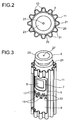
- FIG. 1 an electrode unit according to the invention is shown in the form of a longitudinal section.
- An electrode unit 1 comprises a solid electrolyte 3, which is cylindrical in the embodiment shown here and is closed on one side.
- the solid electrolyte 3 is generally a ceramic membrane which is permeable to specific cations.
- ⁇ "-alumina is suitable as the material for the solid electrolyte 3.
- the solid electrolyte 3 is followed by an intermediate layer 5 which insulates with respect to the electron conduction.
- the electron conduction insulating intermediate layer 5 is, for example, a passivated aluminum fabric, for example, an anodized or sulfide passivated aluminum fabric, or carbon fabric or composed of ceramic fibers or glass fibers.
- electron conduction insulating means in this context that the resistivity of the layer is greater than 10 8 ohms * cm, preferably greater than 10 9 ohm * cm and in particular greater than 2 x 10 9 ohm * cm.
- the electron conduction insulating intermediate layer 5 is enclosed by a porous electrode 7.
- the porous electrode 7 is made of, for example, a graphite felt.
- the porous electrode 7 is in a preferred embodiment, as in FIGS. 2 and 3 represented surrounded by a segment wall 9.
- the segment wall 9 is designed in the form of a sleeve.
- a cover 11 connects.
- the cover 11 is designed in the form of a cladding tube in the embodiment shown here, which has a wave-shaped cross section.
- the cover 11 designed in the form of a cladding tube rests against the segment wall 9 in each case with the wave troughs and forms channels 13 along the segment wall 9 through the wave crests.
- Cathode material flows through the channels 13 during charging or discharging.
- the cathode material is, for example, sulfur or an alkaline polysulfide.
- the cathode material flows out of the flow channel 13 into the porous electrode 7 through inlet openings 15 and is reduced there electrochemically to the anion.
- the anion reacts to form a salt.
- the cations are particularly preferably alkali metal ions, so that an alkali metal salt, in particular an alkali metal polysulfide, very particularly preferably sodium polysulfide, forms in the porous electrode 7.
- the number of sleeves used for the segment wall 9 is dependent on the height of the sleeve and the length of the electrode unit and may also be greater than the number shown here. It is also possible to provide only one sleeve and to form a plurality of rows of inlet openings 15 and outlet openings 17 in the sleeve.
- the porous electrode 7 is segmented by flow barriers 19.
- the flow barrier 19 prevents that formed in the porous electrode 7 reaction product in the region of the outlet openings 17 can continue to flow through the porous electrode 7.
- the flow barrier 19 ensures that the entire material from the porous electrode 7 in the region of the outlet opening 17 exits into the flow channel 13. This ensures that fresh cathode material is supplied to the porous electrode 7 in a subsequent segment and thus the performance of the electrode unit 1 is improved. So that the material which has escaped at an outlet opening 17 does not enter directly into the next segment of the porous electrode, the inlet openings 15 following the outlet openings 17 are arranged offset relative to the outlet openings 17.
- the released during discharging power is tapped via a power connector 21.
- the respective segments of the porous electrode 7 are contacted with the power connector 21.
- the contact is made, for example, via the segment wall 9 and the cover 11.
- both the segment wall 9 and the cover 11 are designed to be electrically conductive.
- the structure contains no segment walls.
- the porous electrodes 7 have direct contact with the wave-shaped cover 11, so that vertically directed flow channels 13 are formed here as well.
- the current leads are in direct electrical contact with the porous electrode 7.
- the porous electrode 7 When discharging, the porous electrode 7 is the cathode.
- the anode is formed by the anode material, which is located on the opposite side of the porous electrode 7 of the solid electrolyte 3.
- the anode material In the embodiment shown here with cylindrical solid electrolyte 3, the anode material is inside the solid electrolyte 3.
- the displacer 23 is designed so that between the solid electrolyte 3 and the displacer 23, a gap 25 is formed.
- the gap 25 contains the anode material.
- the anode material itself is electrically conductive and can be used directly as an electrode when discharging as an anode.
- the displacer 23 is electrically conductive and the displacer 23 forms the power connection.
- a channel 27 is formed in the displacer 23.
- the anode material flows through the channel 27 into the gap 25 and forms in the electrochemical reduction cations, which pass through the cation-conducting solid electrolyte 3 in the porous electrode 7, where they react neutralizing with the anions formed there.
- the displacer 23 In order to adjust the temperature required for operation, so that anode material and cathode material remain molten, it is also possible to heat the displacer 23.
- the heating can be done electrically, for example, with a heating element.
- the heating is distributed in a particular embodiment with different heating power over the length of the electrode unit, so that more is heated at the top and bottom the least. This ensures that the cooled below the melting point alkali metal and the surrounding cathode material melt from top to bottom in the form of a melting cone and thus no destructive acting pressures can be caused by trapped melt.
- the salt for example, sodium polysulfide
- the salt is supplied via the channels 13, enters the porous electrode through the outlet openings 17 and is separated by an applied voltage into sodium ions and sulfur, the sodium ions flowing through the solid electrolyte 3 into the gap 25 and can escape through the channel 27.
- the sulfur exits through the inlet openings 15 in the segment wall 9 from the porous electrode 7 into the flow channel 13.
- the flow is initiated due to the density difference between sodium polysulfide and sulfur. Since the sodium polysulfide has a greater density than sulfur, the sodium polysulfide sinks down and thereby forms a flow, so that the electrode unit 1 can be operated continuously while there is still a supply of alkali metal and sulfur.
- the sulfur and the alkali metal are stored in separately arranged storage containers, wherein the storage container for the sulfur, for example, can also enclose the cover 11 and flows over the channels 13 formed by the cover 11 to the porous electrode 7.
- the formed salt is then also collected in the sulfur storage tank. Due to the difference in density, a two-phase system is formed, with the sodium polysulfide at the bottom and the sulfur at the top.
- FIG. 2 shows a plan view of the inventively constructed electrode unit 1.
- the wavy design of the cover 11 designed as a cladding tube can be seen.
- the wave-shaped cover 11 rests with wave troughs 29 on the segment wall 9, and individual channels 13 are formed by the wave crests 31, which alternate with the wave troughs 29.
- the cathode material flows into the channels 13, which are formed by the wave crests 31, and then enters through inlet openings 15 in the porous electrode.
- the outlet openings 17 the material flowing through the channel mixed with the exiting material, so that in subsequent inlet openings 15 in the same flow channel 13, a mixture enters the contains a higher proportion of unreacted cathode material than the material leaving the outlet openings.
- the electrode unit according to the invention is shown in three dimensions, wherein the cover 11 for displaying the underlying components has a cutout. This is not present in the mounted electrode unit 1.
- the outlet openings 17 are arranged offset to the subsequent inlet openings 15. This avoids that material from an outlet opening 17 can flow directly into the subsequent inlet opening 15.
- the inlet openings 15 and outlet openings 17 are each designed with a rectangular cross-section, wherein between two inlet openings 15 and two outlet openings 17 each have an extension 33 of the sleeve designed as a flat electrode 9, which has the same width as the following Inlet opening 15 and the preceding outlet opening 17th
- the flat electrodes 9 are made as separate sleeves, each having the inlet openings 15 at one end and the outlet openings 17 at the other end.
- the design in individual sleeves allows easier assembly and production.
- the design with separate sleeves, at the ends of each inlet openings 15 and outlet openings 17 are formed.
- the inlet openings 15 and the outlet openings 17 are formed axially aligned with one another in each case on a sleeve.
- inlet openings 15 and outlet openings 17 shown here it is also possible, in addition to the rectangular inlet openings 15 and outlet openings 17 shown here to make the inlet openings and outlet openings in any other form.
- the openings in the form of a semicircle or a semi-ellipse or as a triangle, if the openings are respectively at the end of the sleeve.
- planar electrode in which a plurality of rows of inlet openings 15 and outlet openings 17 are formed, they can also be formed in any other shape, for example elliptical, circular, triangular or polygonal with any number of corners.
- the electrode unit 1 is preferably cylindrical, as shown here.
- FIG. 4 is a sectional view represented by a inventively designed displacer.
- the displacer 23 is made of stainless steel.
- the displacer 23 is preferably designed so that it rests resiliently on the solid electrolyte 3.
- the springy Concerns on the solid electrolyte can be realized, for example, by a design with projections 35 and recesses 37. This leads, for example, to a wave-shaped design of the displacer 23.
- By the resilient abutment of the displacer 23 manufacturing deviations of the inner contour of the solid electrolyte 3 and differences in the thermal expansion can be compensated.
- additional current conductors 39 are provided to make the recesses 37 in the form of an omega, in which the current conductors 39 are clamped with a circular cross-section.
- the current conductors 39 have a shell in the form of a tube 41 sealed on both sides and a core 43 made of a material with good electrical conductivity.
- the core 43 is fully on the pipe 41.
- the tube is preferably made of a stainless steel and the core of aluminum, copper, silver, gold or sodium.
- the use of the current conductor 39 improves the electrical conductivity of the displacer 23 made of comparatively poorly conductive stainless steel.
- the current conductor 39 is protected against corrosion and for the failure of the solid electrolyte 3 against a violent reaction with the cathode material.
- the displacer is usually hollow inside.
- the inner region 45 of the displacer may be used, for example, to contain a sodium-containing container.
- the container is preferably also made of stainless steel.
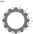
- FIG. 5 shows a sectional view of the planar electrode in an embodiment of the invention.
- the solid electrolyte 3 is enclosed by an electrically insulating layer 5 and a porous electrode 7.
- the cover 11 connects, which is designed wave-shaped in the embodiment shown here.
- the wave-shaped design of the cover 11 flow channels 13 are formed, which are flowed through by sulfur and polysulfide.
- the current conductors 47 are preferably arranged on the side facing the solid electrolyte 3 side of the cover 11.
- the current conductors 47 are accommodated in flow channels 23 of the planar electrode.
- the geometries of flow channels 23 and conductors 47 are adapted to each other so that a current conductor 47 in each case over the entire surface of the wall of a flow channel 13 is present.
- the current conductor 47 as the arranged on the displacement side conductor 39 is made with a shell of a double-sealed stainless steel tube 49 and a core 51 of a good electrically conductive material.
- the electrically highly conductive material is preferably copper, aluminum, silver or gold, more preferably copper or aluminum.
- any other uniform or non-uniform distribution of the current conductors 39 is possible.
- a cover not shown here, surrounds the planar electrode and thus also the electrically highly conductive material.
- the material for the cover while the same material is preferably selected as for the cover 11th
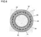
- the displacer comprises an outer shell 62 made of a stainless steel, wherein the outer shell resiliently bears against the solid electrolyte 3.
- the outer shell is wave-shaped in the embodiment shown here and has alternately troughs 29 and crests 31. This shape of the outer shell is suitable for compensating for manufacturing deviations of the inner contour of the solid electrolyte and differences in the thermal expansion.
- a core 64 made of a non-ferrous metal and an inner shell 63 made of stainless steel.
- the core may be cast between the inner shell 63 and the outer shell 62 during manufacture.
- displacer 23 is adapted to the contour of the solid electrolyte 3.
- the non-ferrous metal for the core 64 are, for example, aluminum, zinc, copper or alloys containing at least one of these metals. It is furthermore preferred if in the in FIG. 6 shown displacer core 64 is used for power supply.
- troughs 29 are in the in FIG. 6 illustrated embodiment rails 66 introduced.
- the profile rails 66 By the profile rails 66, the free volume between the solid electrolyte 3 and displacer 23 is reduced, so that the space that can occupy the liquid alkali metal is further reduced.
- the displacer 3 comprises an outer shell 62, an inner shell 63 and a core 64.
- the outer shell 62 and the inner shell 63 are made of a stainless steel or graphite.
- As material for the core 64 a non-ferrous metal is used.
- a sheet-steel jacket made of a stainless steel sheet or a stainless steel foil is produced in such a way that it forms an undersize in the inner contour of the solid electrolyte 3 to form the outer shell 62 fits.
- a steel sheet inner body is introduced concentrically to the formation of the inner shell 63.
- the sheet steel inner body can be constructed the same as the steel jacket for the outer shell 62.
- the non-ferrous metal preferably aluminum, zinc or an alloy containing at least one of these metals, poured, whereby the Core 64 is formed. Due to the pressure, the steel jacket is pressed against the inner contour of the solid electrolyte 3 and thus adapts to the shape of the solid electrolyte 3, so that manufacturing deviations are compensated.
- the non-ferrous metal solidifies and then cools down further. Due to different shrinkage on cooling, a defined minimum shrinkage gap 67 is formed between the solid electrolyte 3 and the outer shell 62 leaving little space for the alkali metal.
- the power supply takes place in this embodiment as well as in FIG. 6 illustrated embodiment preferably via the core 64th
- the steel jacket for the outer shell 62 in the solid electrolyte 3 and insert a hollow body, for example, a heat-resistant aluminum alloy.
- the hollow body made of the heat-resistant aluminum alloy also corresponds to the internal geometry of the solid electrolyte, but has an undersize with respect to the steel jacket for the outer shell 62.
- the hollow body At a temperature below the melting temperature of the hollow body, in which the material of the hollow body, however, is plastically deformable, the hollow body is adapted by internal overpressure and the plastic deformation triggered thereby to the inner wall of the solid electrolyte.
- manufacturing inaccuracies are compensated by the ideal contour of the solid electrolyte 3.
- the steel jacket is pressed by the pressing of the hollow body to the inner contour of the solid electrolyte 3 and thus adapted to this.
- a defined minute shrinkage gap 67 is formed between the inner contour of the solid electrolyte 3 and the sheet steel jacket forming the outer shell 62.
- the power is preferably supplied via the core 64 forming the hollow body.
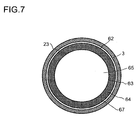
- the structure of the finished displacer 23 substantially corresponds to that of the in the FIGS. 7 and 8th shown.
- a cylindrical bent plate 61 made of stainless steel, for example from a stainless steel foil.
- the cylindrically curved plate 61 has an open longitudinal seam on which this overlaps with its edges.
- the bottom cap with which the displacer 23 is completed may be part of the cylindrically curved sheet 61 or an independent component, as in FIG. 10 shown.
- the bottom 69 has an upwardly facing edge 68 which encloses the cylindrically curved plate 61.
- cylindrically curved plate 61 and bottom 69 are similar to the inner contour of the solid electrolyte 3, but have over this an excess.
- the cylindrically curved plate 61 and possibly the separate bottom 69 is inserted into the solid electrolyte 3 so that cylindrical bent sheet 61 and possibly the bottom 69 spring against the inner contour of the solid electrolyte 3.
- a hollow body 60 is preferably inserted from a heat-resistant aluminum alloy, which has a similar geometry as the inner contour of the solid electrolyte 3, but with respect to this has an undersize.
- the hollow body 60 At a temperature at which the material of the hollow body 60 is plastically deformable, but which is still below the melting temperature of the material of the hollow body 60, the hollow body 60 is adapted to the inner contour of the solid electrolyte by internal overpressure and the resulting plastic deformation.
- the lying between the hollow body 60 cylindrically curved plate 61 and optionally the bottom 69 are pressed against the inner contour of the solid electrolyte 3 and can thus adapt to this.
- a shrinkage gap is formed due to different contraction, so that only little space remains for the alkali metal.
- the power supply is preferably carried out, as in the embodiments described above, via the non-ferrous metal core 64 or a non-ferrous metal-containing alloy.
Description
Die Erfindung betrifft eine Elektrodeneinheit für eine elektrochemische Vorrichtung, umfassend einen Festelektrolyt sowie eine poröse Elektrode, wobei der Festelektrolyt einen Raum für Kathodenmaterial und einen Raum für Anodenmaterial trennt und die poröse Elektrode flächig mit dem Festelektrolyten verbunden ist und das Kathodenmaterial beim Laden oder Entladen entlang der Elektrode strömt.The invention relates to an electrode unit for an electrochemical device comprising a solid electrolyte and a porous electrode, wherein the solid electrolyte separates a space for cathode material and a space for anode material and the porous electrode is connected flat to the solid electrolyte and the cathode material during charging or discharging along the Electrode flows.
Elektrochemische Vorrichtungen können zum Beispiel eingesetzt werden, um elektrische Energie zu speichern. Diese werden im Allgemeinen als Batterie oder Akkumulator bezeichnet. Andere elektrochemische Vorrichtungen sind zum Beispiel Elektrolysezellen. Diese können beispielsweise zur Herstellung von Alkalimetallen aus geeigneten Alkalimetalle enthaltenden Salzen eingesetzt werden.Electrochemical devices can be used, for example, to store electrical energy. These are commonly referred to as a battery or accumulator. Other electrochemical devices are, for example, electrolysis cells. These can be used, for example, for the preparation of alkali metals from salts containing suitable alkali metals.
Die Erzeugung elektrischer Energie ist im Falle fossiler Kraftwerke mit der Erzeugung von CO2 verbunden und hat damit erheblichen Einfluss auf den Treibhauseffekt. Energieerzeugung auf Basis regenerativer Energieträger, zum Beispiel Wind, Sonne, Geothermie oder Wasserkraft vermeidet diesen Nachteil. Diese regenerativen Energieträger sind zeitlich jedoch nicht beliebig lastganggerecht verfügbar. Außerdem differiert gegebenenfalls der Standort der Energieerzeugung vom Ort des Energiebedarfs. Um diesen systembedingten Nachteil zu kompensieren, ist eine Speicherung, Pufferung und gegebenenfalls auch ein Transport der erzeugten Energie erforderlich.The generation of electrical energy in the case of fossil power plants is associated with the production of CO 2 and thus has a significant impact on the greenhouse effect. Energy production based on renewable energy sources, for example wind, sun, geothermal or hydropower avoids this disadvantage. However, these regenerative energy sources are not available at any time in terms of load. In addition, where appropriate, the location of energy production differs from the location of the energy demand. In order to compensate for this system-related disadvantage, storage, buffering and possibly also transportation of the energy generated is required.
Ein ausschließlich auf erneuerbaren Energien basierendes und dennoch stabiles Stromnetz kann es unter diesen Rahmenbedingungen nicht geben. Daher besteht Bedarf, diese Schwankungen durch kostengünstige und energieeffiziente Systeme mit einem hohen Wirkungsgrad auszugleichen und zu puffern.An electricity grid based solely on renewable energies and yet stable can not exist under these conditions. Therefore, there is a need to balance and buffer these fluctuations with low cost and energy efficient systems.
Zur Speicherung elektrischer Energie werden derzeit im technischen Maßstab Pumpspeicherkraftwerke verwendet, in denen die potentielle Energie der geodätischen Höhendifferenz des Wassers zur Umwandlung in Strom genutzt wird. Der Aufbau solcher Pumpspeicherkraftwerke ist jedoch durch landschaftliche und ökologische Rahmenbedingungen limitiert. Druckspeicherkraftwerke, in denen die Kompression von Luft zur Energiespeicherung genutzt wird, sind aufgrund ihres vergleichsweise geringen Wirkungsgrades limitiert. Auch andere Formen der Energiespeicherung wie Superkondensatoren oder Schwungräder adressieren andere Zielmärkte, insbesondere Kurzzeitspeicher. Eine effektive Speicherung elektrischer Energie ist insbesondere mit Batterien möglich, die in verschiedenen Konzepten technisch realisiert wurden. Hierbei ist es insbesondere notwendig, Batterien einzusetzen, die wiederaufladbar sind.For storage of electrical energy pumped storage power plants are currently used on an industrial scale, in which the potential energy of the geodetic height difference of the water is used for conversion into electricity. However, the construction of such pumped storage power plants is limited by landscape and ecological conditions. Pressure accumulator power plants, in which the compression of air is used for energy storage, are limited due to their comparatively low efficiency. Other forms of energy storage such as supercapacitors or flywheels address other target markets, especially short-term storage. An effective storage of electrical energy is possible in particular with batteries that have been technically realized in various concepts. In this case, it is particularly necessary to use batteries that are rechargeable.
Entsprechende. Batterien, die auf Basis eines geschmolzenen Alkalimetalls als Anode und einem kathodischen Reaktionsteilnehmer, im Allgemeinen Schwefel, arbeiten, sind zum Beispiel in
Zur Vergrößerung der Speicherfähigkeit von Batterien auf Basis von einem geschmolzenen Alkalimetall und einem kathodischen Reaktionsteilnehmer werden Batterien eingesetzt, bei denen durch zusätzliche Vorratsbehälter die Menge an den eingesetzten Reaktanden vergrößert wird. Zum Entladen wird das flüssige Natrium dem Festelektrolyten zugeführt. Das flüssige Natrium dient gleichzeitig als Anode und bildet Kationen, die durch den kationenleitenden Festelektrolyten zur Kathode transportiert werden. An der Kathode wird der an die Kathode anströmende Schwefel zu Polysulfid reduziert, also mit den Natriumionen zu Natriumpolysulfid umgesetzt. Das entsprechende Natriumpolysulfid kann in einem weiteren Behälter gesammelt werden. Alternativ ist es auch möglich, das Natriumpolysulfid mit dem Schwefel gemeinsam im Behälter um den Kathodenraum zu sammeln. Aufgrund des Dichteunterschiedes steigt der Schwefel auf und setzt sich das Natriumpolysulfid ab. Diese Dichtedifferenz kann auch dazu genutzt werden, eine Strömung entlang der Kathode zu bewirken. Ein entsprechendes Batteriedesign ist zum Beispiel in
In Batterien, die mit einem Redox-System auf Basis von Natrium und Schwefel arbeiten, kann mit einem hohen Wirkungsgrad von ungefähr 90% bei der Umsetzung von Natrium und Schwefel zu Natriumpolysulfid elektrische Energie gewonnen werden. Zum Laden der Batterie wird der Vorgang durch Einspeisung von Strom umgekehrt und das Natriumpolysulfid wird zu Schwefel und Natrium gespalten. Da alle elektrochemischen Reaktanden schmelzflüssig vorliegen und der optimale Leitfähigkeitsbereich der ionenleitenden keramischen Membran erst bei höheren Temperaturen erreicht wird, liegt die Betriebstemperatur einer solchen Batterie üblicherweise bei etwa 300°C.In batteries operating on a sodium and sulfur based redox system, electrical energy can be obtained with a high efficiency of about 90% in the conversion of sodium and sulfur to sodium polysulfide. To charge the battery, the process is reversed by feeding current and the sodium polysulfide is cleaved to sulfur and sodium. Since all electrochemical reactants are molten and the optimum conductivity range of the ion-conducting ceramic membrane is reached only at higher temperatures, the operating temperature of such a battery is usually about 300 ° C.
Bei dem in der Batterie eingesetzten Natrium-Ionen leitenden Festelektrolyten handelt es sich üblicherweise um β-Aluminiumoxid. Da dies eine Keramik ist, kann ein Bruch des Festelektrolyten nicht ausgeschlossen werden. In einem solchen Fall kann es zu einer ungeregelten Reaktion zwischen Natrium und Schwefel kommen, was aufgrund der exothermen Reaktion zu einem unerwünschten Temperaturanstieg in der Batterie führen kann. Um den Temperaturanstieg in einem solchen Fall möglichst gering zu halten, ist es zum Beispiel aus der
Neben der Verwendung von Aluminium als Material für den Verdränger offenbaren die
Da die mechanische Festigkeit von Edelstahl höher ist als die von Aluminium und damit die plastische Verformung bei Betriebstemperatur der Batterie sehr viel geringer ist, kann sich der Edelstahl bei einer zylindrischen Gestaltung des Verdrängers nicht an die Form des Festelektrolyten anpassen. Aufgrund von thermischer Expansion kann es daher zu einem Bruch des Festelektrolyten kommen, wenn der aus Edelstahl gefertigte Verdränger ungleichmäßig gegen den Festelektrolyten gepresst wird. Eine solche ungleichmäßige Anpressung des Verdrängers an den Festelektrolyten resultiert zum Beispiel aus Fertigungsungenauigkeiten bei der Herstellung des keramischen Festelektrolyten.Since the mechanical strength of stainless steel is higher than that of aluminum and thus the plastic deformation at the operating temperature of the battery is much lower, the stainless steel in a cylindrical design of the displacer can not adapt to the shape of the solid electrolyte. Due to thermal expansion, a breakage of the solid electrolyte can therefore occur if the displacer made of stainless steel is pressed unevenly against the solid electrolyte. Such an uneven contact pressure of the displacer on the solid electrolyte results, for example, from production inaccuracies in the production of the ceramic solid electrolyte.
Aufgabe der vorliegenden Erfindung war es daher, eine Elektrodeneinheit mit einem Verdränger bereitzustellen, die die Nachteile der aus dem Stand der Technik bekannten Elektroden nicht aufweist.It was therefore an object of the present invention to provide an electrode unit with a displacer which does not have the disadvantages of the electrodes known from the prior art.
Gelöst wird die erfindungsgemässe die Aufgabe durch eine Elektrodeneinheit für eine elektrochemische Vorrichtung gemäß Anspruch 1.The object of the invention is achieved by an electrode unit for an electrochemical device according to claim 1.
Durch den Einsatz eines Verdrängers aus Edelstahl oder eines Verdrängers mit einer äußeren Hülle aus Edelstahl wird insbesondere im Fall des Bruchs des Festelektrolyten eine unkontrollierte thermische Zerstörung der gesamten Batterie verhindert, da der Edelstahl erst bei sehr viel höheren Temperaturen und weniger heftig als Aluminium mit dem Schwefel reagiert. Hierdurch lässt sich die Sicherheit beim Betrieb einer solchen Batterie, die auf Basis eines Alkalimetalls und Schwefel arbeitet, deutlich erhöhen. Dadurch, dass der Verdränger federnd an der Innengeometrie des Festelektrolyten anliegt, können Längenänderungen aufgrund thermischer Expansion ausgeglichen werden.By using a displacer made of stainless steel or a displacer with an outer shell made of stainless steel uncontrolled thermal destruction of the entire battery is prevented especially in the case of breakage of the solid electrolyte, since the stainless steel only at much higher temperatures and less violent than aluminum with the sulfur responding. As a result, the safety in the operation of such a battery, which operates on the basis of an alkali metal and sulfur, significantly increase. Due to the fact that the displacer resiliently on the Inner geometry of the solid electrolyte is applied, changes in length due to thermal expansion can be compensated.
Im Rahmen der vorliegenden Erfindung ist unter Anodenmaterial ein flüssiger Reaktand zu verstehen, der auf der Anodenseite beim Entladen zugeführt wird. Bevorzugt ist das Anodenmaterial elektrisch leitend, insbesondere wird als Anodenmaterial ein flüssiges Alkalimetall eingesetzt. Geeignete Anodenmaterialien sind zum Beispiel Lithium, Natrium oder Kalium, insbesondere Natrium oder Kalium.In the context of the present invention, anode material is to be understood as meaning a liquid reactant which is supplied on the anode side during discharge. Preferably, the anode material is electrically conductive, in particular, a liquid alkali metal is used as the anode material. Suitable anode materials are, for example, lithium, sodium or potassium, in particular sodium or potassium.
Das Kathodenmaterial ist ein flüssiger Reaktionspartner, der mit dem Anodenmaterial elektrochemisch umgesetzt wird. Üblicherweise bildet das Kathodenmaterial mit dem Anodenmaterial durch chemische Reaktion ein Salz. Geeignete Kathodenmaterialien sind zum Beispiel Schwefel oder Polysulfide. Das Kathodenmaterial wird dabei flüssig eingesetzt. Weiterhin eignet sich als Kathodenmaterial auch ein Gemisch aus Natriumchlorid und einem Metall der 8. Nebengruppe, beispielsweise Eisen, Nickel oder Kobalt, in Kombination mit einem schmelzflüssigen Elektrolyten wie NaAlCl4.The cathode material is a liquid reactant that is electrochemically reacted with the anode material. Usually, the cathode material forms a salt with the anode material by chemical reaction. Suitable cathode materials are, for example, sulfur or polysulfides. The cathode material is used liquid. Furthermore, suitable as a cathode material, a mixture of sodium chloride and a metal of subgroup 8, such as iron, nickel or cobalt, in combination with a molten electrolyte such as NaAlCl. 4
Weitere geeignete Kathodenmaterialien in Verbindung mit einem Alkalimetall als Anodenmaterial sind zum Beispiel Stickstoffoxide (NO oder NO2), ein Halogen, beispielsweise Chlor, Jod oder Brom, ein Metallhalogenid, beispielsweise NiCl2 oder FeCl3, ein Metalloidhalogenid, beispielsweise SiCl4 oder Si2Cl6. Auch ist der Einsatz eines festen Salzes, das sein Redoxpotential ändern kann, möglich. Ein solches Salz ist zum Beispiel NaFePO4.Other suitable cathode materials in conjunction with an alkali metal anode material are, for example, nitrogen oxides (NO or NO 2 ), a halogen, for example chlorine, iodine or bromine, a metal halide, for example NiCl 2 or FeCl 3 , a metalloid halide, for example SiCl 4 or Si 2 Cl 6 . Also, the use of a solid salt, which can change its redox potential, possible. Such a salt is, for example, NaFePO 4 .
Bevorzugt werden gasförmige Kathodenmaterialien, wobei die Betriebsbedingungen, insbesondere Druck und Temperatur der elektrochemischen Vorrichtung, so angepasst werden können, dass das Kathodenmaterial gasförmig vorliegt. So ist es zum Beispiel möglich, bei Einsatz von Schwefel als Kathodenmaterial, den Schwefel nicht nur als Schmelze sondern alternativ auch als Schwefeldampf zuzuführen. Zur Verbesserung der Leitfähigkeit ist es bei Einsatz von gasförmigen Kathodenmaterialien möglich, zusätzlich einen flüssigen Elektrolyten einzusetzen. Dieser muss dabei kompatibel zum eingesetzten Redoxpaar sein. Beim Einsatz von Natrium und Schwefel sind dies beispielsweise Alkalimetallsalze mit Schwefelsauerstoffanionen wie Natriumsulfit oder Natriumthiosulfat. Bei Einsatz von Alkalimetall und Stickstoffoxid eignen sich zum Beispiel Alkalimetallnitrate und -nitrite. Bei Einsatz eines Halogens können Komplexsalze aus einem Alkalimetallhalogenid und einem Metallhalogenid, beispielsweise NaAlCl4 oder NaZnCl3, eingesetzt werden.Preference is gaseous cathode materials, wherein the operating conditions, in particular pressure and temperature of the electrochemical device, can be adjusted so that the cathode material is present in gaseous form. For example, when sulfur is used as the cathode material, it is possible to supply the sulfur not only as a melt but alternatively as sulfur vapor. To improve the conductivity, it is possible with the use of gaseous cathode materials to additionally use a liquid electrolyte. This must be compatible with the redox couple used. When using sodium and sulfur, these are for example alkali metal salts with sulfur oxygen anions such as sodium sulfite or sodium thiosulfate. When using alkali metal and nitrogen oxide, for example, alkali metal nitrates and nitrites are suitable. When using a halogen complex salts of an alkali metal halide and a metal halide, for example NaAlCl 4 or NaZnCl 3 , can be used.
Eine elektrochemische Vorrichtung im Sinne der vorliegenden Erfindung ist eine Vorrichtung zur Speicherung elektrischer Energie, die auch als Batterie oder Akkumulator bezeichnet wird, oder eine Elektrolysezelle.An electrochemical device according to the present invention is a device for storing electrical energy, which is also referred to as a battery or accumulator, or an electrolysis cell.
Der Transport durch die poröse Elektrode erfolgt vorzugsweise allein aufgrund von Konvektion und Diffusion. Hierdurch ist es möglich, auf Pumpen oder ähnliche Vorrichtungen, mit denen ein erzwungener Transport gefördert wird, zu verzichten. Der Nachteil solcher Vorrichtungen ist im Allgemeinen, dass diese elektrische Energie benötigen, die dann nicht mehr zur Verfügung steht. Weiterer Nachteil von Vorrichtungen für erzwungenen Transport ist deren Verschleiß.The transport through the porous electrode preferably takes place solely on the basis of convection and diffusion. This makes it possible to dispense with pumps or similar devices, with which a forced transport is promoted. The disadvantage of such devices is in Generally that they require electrical energy, which is then no longer available. Another disadvantage of forced transport devices is their wear.
Ein Vorteil des Einsatzes eines Verdrängers ist, dass hierdurch die Menge an flüssigem Anodenmaterial reduziert werden kann. Das Anodenmaterial fließt bei Verwendung eines Verdrängers in einem Raum zwischen dem Verdränger und dem Festelektrolyten. Durch den Einsatz des Verdrängers wird der Raum, in dem sich das Anodenmaterial befindet, auf einen Spalt oder in Abhängigkeit der Ausgestaltung des Verdrängers auch auf mehrere kleine Kanäle reduziert, durch die das Anodenmaterial fließen kann. Der Zulauf des Anodenmaterials kann dabei zum Beispiel über einen Ringspalt am Ende des Festelektrolyten erfolgen oder alternativ durch einen Strömungskanal im Verdränger zugeführt werden. Bevorzugt ist die Zufuhr des Anodenmaterials durch einen Strömungskanal im Verdränger.An advantage of using a displacer is that it can reduce the amount of liquid anode material. The anode material flows when using a displacer in a space between the displacer and the solid electrolyte. Through the use of the displacer, the space in which the anode material is located is reduced to a gap or, depending on the design of the displacer, also to a plurality of small channels through which the anode material can flow. The feed of the anode material can take place for example via an annular gap at the end of the solid electrolyte or alternatively be supplied through a flow channel in the displacer. Preferably, the supply of the anode material through a flow channel in the displacer.
Besonders bevorzugt werden der Verdränger beziehungsweise die äußere Hülle des Verdrängers aus Edelstahl gefertigt. Als Edelstahl eignen sich insbesondere Molybdän stabilisierte Edelstähle 1.4571, 1.4401, 1.4404, 1.4405 und 1.4539. Weiterhin ist der Verdränger vorzugsweise aus einem Edelstahlblech gefertigt.Particularly preferably, the displacer or the outer shell of the displacer are made of stainless steel. Particularly suitable stainless steels are molybdenum-stabilized stainless steels 1.4571, 1.4401, 1.4404, 1.4405 and 1.4539. Furthermore, the displacer is preferably made of a stainless steel sheet.
Eine möglichst geringe Belastung des Festelektrolyten wird zusätzlich dadurch erzielt, dass zur Fertigung des Verdrängers ein Edelstahlblech mit einer Dicke im Bereich von 0,05 bis 0,5 mm, vorzugsweise im Bereich von 0,07 bis 0,15 mm, beispielsweise 0,1 mm, eingesetzt wird.The lowest possible loading of the solid electrolyte is additionally achieved by producing a stainless steel sheet having a thickness in the range from 0.05 to 0.5 mm, preferably in the range from 0.07 to 0.15 mm, for example 0.1, for the production of the displacer mm, is used.
Um eine federnd an die Innengeometrie anliegende Form zu erhalten, weist der Verdränger vorzugsweise eine Außenkontur mit Vorsprüngen und Rücksprüngen auf. Die Vorsprünge und Rücksprünge können zum Beispiel durch eine wellenförmige oder eine Zick-zack-förmige Gestaltung des Verdrängers realisiert werden.In order to obtain a resiliently fitting to the internal geometry form, the displacer preferably has an outer contour with projections and recesses. The projections and recesses can be realized for example by a wave-shaped or a zigzag-shaped design of the displacer.
Wenn der Verdränger eine äußere Hülle aus Edelstahl oder Graphit und einen Kern aus einem Nichteisenmetall umfasst, ist die äußere Hülle aus Edelstahl oder Graphit in einer ersten Ausführungsform eine flexible Folie aus Edelstahl oder Graphit. In einer zweiten, alternativen Ausführungsform umfasst die äußere Hülle ein zylinderförmig gebogenes Blech, dessen Kanten in axialer Richtung überlappen. Zusätzlich kann die äußere Hülle beschichtet sein. So ist es zum Beispiel möglich, mit Graphit beschichteten Edelstahl für die äußere Hülle einzusetzen. Das Graphit kann dabei zum Beispiel in Form eines Graphitfilzes vorliegen. Alternativ ist es auch möglich, Graphitfilz als Material für die äußere Hülle zu verwenden.When the displacer comprises an outer shell of stainless steel or graphite and a core of non-ferrous metal, the outer shell of stainless steel or graphite in a first embodiment is a flexible sheet of stainless steel or graphite. In a second, alternative embodiment, the outer shell comprises a cylindrically curved metal sheet whose edges overlap in the axial direction. In addition, the outer shell may be coated. For example, it is possible to use graphite coated stainless steel for the outer shell. The graphite can be present for example in the form of a graphite felt. Alternatively, it is also possible to use graphite felt as a material for the outer shell.
Wenn die äußere Hülle ein zylinderförmig gebogenes Blech umfasst, dessen Kanten in axialer Richtung überlappen, ist es weiterhin bevorzugt, wenn ein Boden umfasst ist, der mit einem nach oben gebogenen Rand das zylinderförmig gebogene Blech umschließt oder der von dem zylinderförmig gebogenen Blech umschlossen wird, so dass der Boden bei der Herstellung des Verdrängers relativ zur äußeren Hülle beweglich ist.If the outer shell comprises a cylindrically curved metal sheet whose edges overlap in the axial direction, it is further preferred if a base is encompassed which encloses the cylindrically curved metal sheet with an upwardly bent edge or which is enclosed by the cylindrically curved metal sheet, so that the bottom is movable relative to the outer shell in the manufacture of the displacer.
Zusätzlich zu der äußeren Hülle weist der Verdränger in einer weiteren Ausführungsform auch eine innere Hülle auf, wobei der Verdränger in diesem Fall als Hohlkörper aufgebaut ist. Zwischen der inneren und der äußeren Hülle aus Edelstahl oder Graphit befindet sich ein Kern aus dem Nichteisenmetall.In addition to the outer shell, the displacer in a further embodiment also has an inner shell, wherein the displacer is constructed in this case as a hollow body. Between the inner and outer sheath of stainless steel or graphite is a core of non-ferrous metal.
Als Nichteisenmetall für den Verdränger eignen sich zum Beispiel Aluminium, Zink oder eine mindestens eines dieser Metalle enthaltende Legierung.Suitable non-ferrous metal for the displacer are, for example, aluminum, zinc or an alloy containing at least one of these metals.
Zur Herstellung des Verdrängers werden die Folie aus Edelstahl oder Graphit oder das zylinderförmig gebogene Blech und gegebenenfalls der Boden in den Festelektrolyten eingelegt. Hierbei ist es insbesondere bevorzugt, wenn die Folie oder das zylinderförmig gebogene Blech und gegebenenfalls der Boden am Festelektrolyten anliegen. Anschließend wird das Nichteisenmetall eingebracht. Danach wird das Nichteisenmetall zusammen mit dem Festelektrolyten und der Edelstahlfolie oder der Graphitfolie so weit erwärmt, dass dieses plastisch verformbar ist, aber noch nicht schmelzflüssig. Alternativ ist es auch möglich, einen bereits erwärmten Rohling aus Nichteisenmetall einzubringen.To produce the displacer, the foil made of stainless steel or graphite or the cylindrically curved metal sheet and optionally the bottom are placed in the solid electrolyte. In this case, it is particularly preferred if the film or the cylindrically curved metal sheet and optionally the bottom rest against the solid electrolyte. Subsequently, the non-ferrous metal is introduced. Thereafter, the non-ferrous metal is heated together with the solid electrolyte and the stainless steel foil or the graphite foil so far that it is plastically deformable, but not yet molten. Alternatively, it is also possible to introduce an already heated blank made of non-ferrous metal.
Auf das Nichteisenmetall wird ein innerer Druck ausgeübt, so dass mit dem Nichteisenmetall die Folie oder das Blech und gegebenenfalls der Boden an den Festelektrolyten gepresst werden. Beim Abkühlen schrumpft das Nichteisenmetall, wobei die Folie oder das zylinderförmig gebogene Blech und gegebenenfalls der Boden am Nichteisenmetall haften, so dass sich ein Spalt zwischen dem Festelektrolyten und der Folie oder dem zylinderförmig gebogenen Blech und gegebenenfalls dem Boden aus Edelstahl oder Graphit bildet. Dieser Spalt ist dabei ausreichend groß, dass das geschmolzene Alkalimetall durch den Spalt fließen kann und mit dem Festelektrolyten in Kontakt kommt, so dass die elektrochemische Vorrichtung betrieben werden kann.An internal pressure is exerted on the non-ferrous metal so that the non-ferrous metal presses the foil or the sheet and, if appropriate, the bottom against the solid electrolyte. Upon cooling, the non-ferrous metal shrinks, the film or the cylindrically curved sheet and possibly the bottom adhering to the non-ferrous metal, so that a gap between the solid electrolyte and the film or the cylindrically curved sheet and optionally the bottom of stainless steel or graphite forms. This gap is sufficiently large that the molten alkali metal can flow through the gap and come into contact with the solid electrolyte, so that the electrochemical device can be operated.
Neben der Herstellung durch Einlegen einer Folie oder eines Blechs für die äußere Hülle und dem nachfolgenden Einbringen des Nichteisenmetalls ist es auch möglich, einen mit Graphit oder Edelstahl beschichteten Rohling aus Nichteisenmetall in den Festelektrolyten einzubringen, diesen zu erwärmen und dann durch Aufbringen eines inneren Drucks an den Festelektrolyten zu pressen. Das Erwärmen kann dabei vor oder nach dem Einbringen des beschichteten Rohlings aus Nichteisenmetall erfolgen.In addition to the production by inserting a film or a sheet for the outer shell and the subsequent introduction of the non-ferrous metal, it is also possible to introduce a graphite or stainless steel coated blank made of non-ferrous metal in the solid electrolyte, to heat it and then by applying an internal pressure to press the solid electrolyte. The heating can be carried out before or after the introduction of the coated blank of non-ferrous metal.
Da Edelstahl ein nur mäßiger elektrischer Leiter ist, ist es weiterhin bevorzugt, wenn der Verdränger zusätzlich Mittel zur Stromleitung umfasst. Über die Mittel zur Stromleitung wird eine gleichmäßige Stromversorgung sowohl beim Laden als auch beim Entladen sichergestellt. Als Mittel zur Stromleitung eignen sich zum Beispiel vorzugsweise gleichmäßig über den Umfang des Verdrängers verteilte Stromsammler, die in einer bevorzugten Ausführungsform aus einem beidseitig verschlossenen Rohr aus Edelstahl gefertigt sind, in das ein Kern aus einem elektrisch gut leitenden Material eingebracht ist. Das Rohr aus Edelstahl liegt dabei vollflächig am Kern aus dem elektrisch gut leitenden Material an. Durch das Rohr aus Edelstahl wird der elektrisch gut leitende Kern vor einem Angriff durch Schwefel und Polysulfid im Falle eines Bruchs des Festelektrolyten geschützt.Since stainless steel is only a moderate electrical conductor, it is further preferred if the displacer additionally comprises means for power line. The means for power line ensures a uniform power supply both when charging and when unloading. As a means for power line, for example, are preferably uniformly distributed over the circumference of the displacer current collector, which are made in a preferred embodiment of a sealed on both sides of stainless steel tube, in which a core is made of a highly electrically conductive material. The tube made of stainless steel lies all over the core of the electrically highly conductive material. Through the tube of stainless steel is the electrically well conductive core protected from attack by sulfur and polysulfide in case of breakage of the solid electrolyte.
In einer alternativen Ausführungsform umfassen die Mittel zur Stromleitung eine vollflächige oder strukturierte Beschichtung aus einem elektrisch gut leitenden Material auf der Innenseite des Verdrängers.In an alternative embodiment, the means for power line comprise a full-surface or structured coating of a highly electrically conductive material on the inside of the displacer.
Als elektrisch gut leitendes Material für die Mittel zur Stromleitung eignen sich zum Beispiel Kupfer, Aluminium, Silber oder Gold. Wenn ein Stromsammler mit einem Rohr aus Edelstahl eingesetzt wird, kann das elektrisch gut leitende Material auch Natrium sein. Bei Betriebstemperatur von üblicherweise 300°C wird das Natrium zwar flüssig, kann jedoch aufgrund des Rohrs aus Edelstahl nicht entweichen. Besonders bevorzugt ist das elektrisch gut leitende Material Kupfer oder Aluminium. Neben den reinen Metallen können auch Mischungen oder Legierungen eingesetzt werden, die mindestens eines dieser Metalle enthalten. Besonders bevorzugt ist jedoch der Einsatz in ungemischtem oder unlegiertem Zustand.For example, copper, aluminum, silver or gold are suitable as electrically highly conductive material for the means for the power line. If a current collector is used with a stainless steel tube, the electrically good conducting material may also be sodium. At operating temperature of usually 300 ° C, the sodium is indeed liquid, but can not escape due to the stainless steel tube. The electrically highly conductive material is particularly preferably copper or aluminum. In addition to the pure metals, it is also possible to use mixtures or alloys which contain at least one of these metals. However, the use in unmixed or unalloyed state is particularly preferred.
Um eine gute Funktion der Elektrodeneinheit zu gewährleisten ist es notwendig, dass die Mittel zur Stromleitung gut elektrisch leitend mit dem Verdränger verbunden sind. Hierzu ist es bei Verwendung der Stromsammler zum Beispiel möglich, die Stromsammler jeweils mit dem Verdränger zu verschweißen. Bevorzugt ist es jedoch, die Stromsammler in Rücksprünge des Verdrängers zu klemmen. Die Stromsammler sind dabei vorzugsweise auf der Außenseite des Verdrängers angeordnet.In order to ensure a good function of the electrode unit, it is necessary that the means for power line are well connected electrically conductive with the displacer. For this purpose, it is possible when using the current collector, for example, to weld the current collector in each case with the displacer. However, it is preferred to clamp the current collector in recesses of the displacer. The current collector are preferably arranged on the outside of the displacer.
Um die Stromsammler fest mit dem Verdränger zu verbinden, ist es zum Beispiel möglich, die Rücksprünge in Form eines Omega zu gestalten, wobei der Durchmesser des Omega dem Außendurchmesser des Drahtes entspricht. Bei einer entsprechenden Gestaltung der Rücksprünge können die Drähte jeweils mit einer stabilen Verbindung in die Rücksprünge geklemmt werden und bilden einen gleichmäßigen Kontakt mit dem Verdränger über die gesamte Länge.For example, to firmly connect the current collectors to the displacer, it is possible to make the recesses in the form of an omega, with the diameter of the omega corresponding to the outside diameter of the wire. With a corresponding design of the recesses, the wires can each be clamped with a stable connection in the recesses and form a uniform contact with the displacer over the entire length.
Wenn der Verdränger eine äußere Hülle und einen Kern aus Nichteisenmetall umfasst, ist es möglich, den Kern aus Nichteisenmetall zur Stromleitung zu nutzen.If the displacer comprises an outer shell and a core of non-ferrous metal, it is possible to use the non-ferrous metal core for power conduction.
Die Elektrode auf der Seite des Festelektrolyten, auf der sich der Raum für das Kathodenmaterial befindet, kann wie aus dem Stand der Technik bekannt gestaltet sein.The electrode on the side of the solid electrolyte on which the space for the cathode material is located may be configured as known in the art.
Um insbesondere bei großen elektrochemischen Vorrichtungen zur Speicherung elektrischer Energie, im Folgenden auch Batterie genannt, eine gleichmäßige Funktion der gesamten Elektrode zu erhalten, ist in einer bevorzugten Ausführungsform für große Vorrichtungen zur elektrochemischen Energiespeicherung die flächige Rohr- oder Blechwand wellblechartig strukturiert, so dass sich zwischen der Grenze des porösen Elektrodenmaterials und der wellblechartigen Rohr- oder Blechwand abwechselnde senkrecht ausgerichtete Längskanäle bilden, die aber mit den Hohlräumen des Elektrodenmaterials kommunizieren können. In diesen Längskanälen kann sich, getrieben vom Dichteunterschied beispielsweise zwischen Polysulfid und Schwefel eine Konvektionsströmung ausbilden, die beim Laden nach oben und beim Entladen nach unten gerichtet ist.In order to obtain a uniform function of the entire electrode, especially in large electrochemical devices for storing electrical energy, hereinafter also called battery, in a preferred embodiment for large devices for electrochemical energy storage, the sheet-like tube or sheet metal wall corrugated like a sheet, so that between form the boundary of the porous electrode material and the corrugated sheet-like tube or sheet wall alternating vertically oriented longitudinal channels, but which can communicate with the cavities of the electrode material. In these longitudinal channels can, driven by the density difference, for example, between polysulfide and sulfur form a convection flow which is directed upwards during loading and downwards during unloading.
In einer weiteren besonders bevorzugten Ausführungsform ist das poröse Elektrodenmaterial in Längssegmente unterteilt, wobei zwischen den Längssegmenten vorzugsweise Strömungssperren angeordnet sind, um einen Massenaustausch von flüssigem Kathodenmaterial zwischen poröser Elektrode und Längskanal zu erzwingen.In a further particularly preferred embodiment, the porous electrode material is subdivided into longitudinal segments, wherein flow barriers are preferably arranged between the longitudinal segments in order to force a mass exchange of liquid cathode material between the porous electrode and the longitudinal channel.
In einer weiteren Ausführungsform werden die porösen Elektrodensegmente zusätzlich mittels seitlich geschlossener Segmentwände gekammert, um eine gezielte Anströmung und Abströmung aus der porösen Elektrode zu erzwingen. Somit weist die Segmentwand in dieser bevorzugten Ausführungsform mehrere quer zur Strömungsrichtung ausgerichtete Reihen an Eintrittsöffnungen und Austrittsöffnungen auf, wobei sich jeweils in Strömungsrichtung Eintrittsöffnungen und Austrittsöffnungen abwechseln und in Strömungsrichtung jeweils vor den Eintrittsöffnungen und nach den Austrittsöffnungen Strömungssperren in der porösen Elektrode aufgenommen sind.In a further embodiment, the porous electrode segments are additionally chambered by means of laterally closed segment walls in order to force a targeted flow and outflow from the porous electrode. Thus, the segment wall in this preferred embodiment, a plurality of aligned transversely to the flow direction rows of inlet openings and outlet openings, each alternating in the flow direction inlet openings and outlet openings and are included in the flow direction in each case before the inlet openings and after the outlet openings flow barriers in the porous electrode.
Beim Entladen der Batterie, d.h. bei der Abgabe elektrischer Energie, tritt das Kathodenmaterial durch die Eintrittsöffnungen in die poröse Elektrode ein und wird mit dem Anodenmaterial elektrochemisch umgesetzt. Durch die Austrittsöffnungen tritt dann das Reaktionsprodukt aus. Die Strömungssperren in der porösen Elektrode dienen dazu, dass das Reaktionsprodukt gezwungen wird, an den Austrittsöffnungen auszutreten, so dass das Reaktionsprodukt nicht weiter in der porösen Elektrode strömen kann. Dies ermöglicht es, dass Kathodenmaterial durch den Austrittsöffnungen nachfolgende Eintrittsöffnungen in die poröse Elektrode eintreten und dort umgesetzt werden kann. Hierdurch kann die gesamte Länge der Elektrode gleichmäßig zur elektrochemischen Umsetzung des Anodenmaterials mit dem Kathodenmaterial genutzt werden.When discharging the battery, i. upon the delivery of electrical energy, the cathode material enters the porous electrode through the entrance openings and is electrochemically reacted with the anode material. Through the outlet openings then exits the reaction product. The flow barriers in the porous electrode serve to force the reaction product to exit at the exit ports so that the reaction product can not flow further into the porous electrode. This makes it possible for cathode material to enter into the porous electrode through the outlet openings and to be converted there. In this way, the entire length of the electrode can be used evenly for the electrochemical conversion of the anode material with the cathode material.
Um die gesamte Fläche der porösen Elektrode ausnutzen zu können, ist es weiterhin bevorzugt, wenn jeweils auf eine Reihe Austrittsöffnungen unmittelbar eine Reihe Eintrittsöffnungen folgt. In diesem Fall strömen das gegebenenfalls nicht umgesetzte Kathodenmaterial und das Reaktionsprodukt bis zu einer Strömungssperre und treten durch die Austrittsöffnungen aus der Elektrode aus, und direkt unterhalb der Strömungssperre wird frisches Kathodenmaterial, das mit dem Anodenmaterial umgesetzt wird, der porösen Elektrode zugeführt.In order to be able to utilize the entire surface of the porous electrode, it is further preferred if in each case a row of outlet openings directly followed by a row of inlet openings. In this case, the optionally unreacted cathode material and the reaction product flow to a flow barrier and exit through the exit openings from the electrode, and directly below the flow barrier fresh cathode material which is reacted with the anode material, the porous electrode.
Um zu vermeiden, dass das in der porösen Elektrode gebildete Reaktionsprodukt, das durch die Austrittsöffnungen austritt, unmittelbar in die dahinterliegenden Eintrittsöffnungen wieder in die poröse Elektrode eintritt, ist es weiterhin bevorzugt, wenn die in Strömungsrichtung des Kathodenmaterials auf die Austrittsöffnungen folgenden Eintrittsöffnungen zu den Austrittsöffnungen versetzt angeordnet sind.In order to avoid that the reaction product formed in the porous electrode, which exits through the outlet openings, enters the porous electrode again directly into the inlet openings behind it, it is further preferred if the inlet openings following the exit openings in the flow direction of the cathode material to the outlet openings are arranged offset.
Hierbei ist es zum Beispiel möglich, die Eintrittsöffnungen und die Austrittsöffnungen jeweils mit einem rechteckigen Querschnitt zu gestalten und jeweils zwischen zwei benachbarten Eintrittsöffnungen bzw. zwei benachbarten Austrittsöffnungen in der Breite der Eintrittsöffnungen bzw. Austrittsöffnungen einen Steg der flächigen Elektrode vorzusehen. Für die versetzte Anordnung schließt sich dann jeweils an eine Eintrittsöffnung der Steg zwischen zwei Austrittsöffnungen und an eine Austrittsöffnung der Steg zwischen zwei Eintrittsöffnungen an.In this case, it is possible, for example, to design the inlet openings and the outlet openings each with a rectangular cross section and in each case between two adjacent inlet openings or two adjacent outlet openings in the width of the inlet openings or outlet openings to provide a web of the planar electrode. For the staggered arrangement then follows in each case at an inlet opening of the web between two outlet openings and at an outlet opening of the web between two inlet openings.
Neben einer Gestaltung mit rechteckförmigen Eintrittsöffnungen und Austrittsöffnungen ist es auch möglich, die Eintrittsöffnungen und Austrittsöffnungen in jeder beliebigen anderen Form zu gestalten. So können diese zum Beispiel kreisförmig, halbkreisförmig, elliptisch, oval, dreieckig oder in Form eines Polygons mit beliebig vielen Ecken gestaltet sein. Bevorzugt ist dabei eine kreisförmige, eine halbkreisförmige oder eine rechteckige Form der Eintrittsöffnungen und Austrittsöffnungen. Auch ist es möglich, Eintrittsöffnungen und Austrittsöffnungen in unterschiedlicher Form vorzusehen, wobei eine gleiche Form von Eintrittsöffnungen und Austrittsöffnungen bevorzugt ist.In addition to a design with rectangular inlet openings and outlet openings, it is also possible to design the inlet openings and outlet openings in any other form. For example, they may be circular, semicircular, elliptical, oval, triangular or polygonal with any number of corners. Preference is given to a circular, semi-circular or rectangular shape of the inlet openings and outlet openings. It is also possible to provide inlet openings and outlet openings in different forms, wherein a same shape of inlet openings and outlet openings is preferred.
Erfindungsgemäß ist die Segmentwand elektrisch leitend mit der porösen Elektrode verbunden. Beim Entladen der Vorrichtung wird die bei der elektrochemischen Umsetzung des Anodenmaterials mit dem Kathodenmaterial frei werdende elektrische Spannung über die poröse Elektrode an die Segmentwand geleitet und kann von der Segmentwand abgenommen werden. Hierzu ist es insbesondere bevorzugt, wenn die Segmentwand elektrisch leitend mit einem oder mehreren Sammelleitern verbunden ist. Um das materialbedingte Risiko einer unerwünschten exothermen Reaktion des Stromleiters mit Schwefel oder Polysulfid zu vermeiden, werden in einer bevorzugten Ausführungsform die Sammelleiter aus gut leitenden Materialien wie Aluminium, Kupfer oder Natrium mit Edelstahl ummantelt oder gekammert. Der Sammelleiter kann dabei auch in Form einer Abdeckung gestaltet sein, die vorzugsweise so ausgebildet ist, dass durch die Abdeckung Strömungskanäle entlang der Elektrode ausgebildet werden. Alternativ ist es auch möglich, eine Abdeckung vorzusehen, die so gestaltet ist, dass Strömungskanäle entlang der Elektrode ausgebildet werden, die elektrische Kontaktierung durch die Abdeckung hindurchzuführen und den Sammelleiter außerhalb der Abdeckung anzuordnen. Bevorzugt ist es jedoch, die Abdeckung elektrisch leitend als Sammelleiter zu gestalten. Hierbei ist es weiter bevorzugt, wenn in der Abdeckung zusätzlich Stabelektroden aufgenommen sind, wobei die Stabelektroden vorzugsweise aus einem elektrisch gut leitenden Material gefertigt sind, das sich vom Material der Abdeckung unterscheidet. Die Stabelektroden können dabei zum Beispiel außen auf der Abdeckung aufliegen oder sind von dem Material für die Abdeckung umschlossen. Bevorzugt sind die einzelnen Stabelektroden dabei äquidistant in der Abdeckung angeordnet. So ist es zum Beispiel möglich, die Stabelektroden jeweils zwischen zwei Strömungskanälen anzuordnen. Alternativ können die Stabelektroden jedoch zum Beispiel auch jeweils im Bereich eines Strömungskanals angeordnet sein.According to the invention, the segment wall is electrically conductively connected to the porous electrode. When discharging the device, the electrical voltage released during the electrochemical conversion of the anode material with the cathode material is conducted via the porous electrode to the segment wall and can be removed from the segment wall. For this purpose, it is particularly preferred if the segment wall is electrically conductively connected to one or more bus bars. In order to avoid the material-related risk of unwanted exothermic reaction of the conductor with sulfur or polysulfide, in a preferred embodiment, the bus bars made of highly conductive materials such as aluminum, copper or sodium are sheathed or chambered with stainless steel. The bus bar can also be designed in the form of a cover, which is preferably designed such that flow channels are formed along the electrode through the cover. Alternatively, it is also possible to provide a cover which is designed such that flow channels are formed along the electrode, to pass the electrical contact through the cover and to arrange the bus bar outside the cover. However, it is preferred to make the cover electrically conductive as a bus bar. In this case, it is further preferred if additional stick electrodes are accommodated in the cover, wherein the stick electrodes are preferably made of a good electrically conductive material, which differs from the material of the cover. The rod electrodes can for example rest on the outside of the cover or are enclosed by the material for the cover. Preferably, the individual stick electrodes are arranged equidistantly in the cover. For example, it is possible to arrange the stick electrodes between two flow channels. Alternatively, however, the rod electrodes can also be arranged, for example, in each case in the region of a flow channel.
In einer besonders bevorzugten Ausführungsform ist zur Ausbildung der Strömungskanäle die Abdeckung wellenförmig gestaltet, wobei jeweils die Wellentäler an der flächigen Elektrode anliegen und die Strömungskanäle durch die entsprechenden Wellenberge gebildet werden. Neben einer wellenförmigen Gestaltung ist es alternativ zum Beispiel auch möglich, die Abdeckung flach mit Stegen zu gestalten, wobei die Strömungskanäle jeweils zwischen zwei Stegen ausgebildet sind und die Stege zur Ausbildung der Strömungskanäle auf der flächigen Elektrode anliegen.In a particularly preferred embodiment, the cover is designed wave-shaped to form the flow channels, wherein in each case the wave troughs abut against the planar electrode and the flow channels are formed by the corresponding wave crests. In addition to a wave-shaped design, it is alternatively possible, for example, to make the cover flat with webs, the flow channels each between two webs are formed and bear the webs to form the flow channels on the flat electrode.
In einer besonders bevorzugten Ausführungsform ist der Festelektrolyt zylinderförmig ausgebildet und die poröse Elektrode umschließt den Festelektrolyten. In diesem Fall befindet sich das Anodenmaterial im Inneren des zylinderförmig ausgebildeten Festelektrolyten und das Kathodenmaterial strömt außen entlang der porösen Elektrode. Bei einer zylinderförmigen Gestaltung des Festelektrolyten wird die Segmentwand vorzugsweise durch mindestens eine Hülse gebildet, die die poröse Elektrode umschließt. Die Eintrittsöffnungen und Austrittsöffnungen sind dabei in der Hülse ausgebildet. Um einen Stromfluss von der porösen Elektrode zur hülsenför-mig ausgebildeten flächigen Elektrode zu erhalten, entspricht dabei der Außendurchmesser der porösen Elektrode dem Innendurchmesser der Hülse. Hierdurch liegt die Hülse flächig an der porösen Elektrode an.In a particularly preferred embodiment, the solid electrolyte is cylindrical and the porous electrode encloses the solid electrolyte. In this case, the anode material is inside the cylindrical solid electrolyte, and the cathode material flows outside along the porous electrode. In a cylindrical design of the solid electrolyte, the segment wall is preferably formed by at least one sleeve which surrounds the porous electrode. The inlet openings and outlet openings are formed in the sleeve. In order to obtain a current flow from the porous electrode to the sleeve-shaped flat electrode, the outer diameter of the porous electrode corresponds to the inner diameter of the sleeve. As a result, the sleeve lies flat against the porous electrode.
Wenn die Segmentwand durch nur eine Hülse gebildet wird, so ist es möglich, mehrere Reihen an Eintrittsöffnungen und Austrittsöffnungen in der Hülse auszubilden. Bevorzugt ist jedoch eine Gestaltung mit mehreren Hülsen, wobei die Eintrittsöffnungen und Austrittsöffnungen in diesem Falle jeweils an den Enden einer Hülse ausgebildet sind. Hierzu ist es zum Beispiel möglich, die Enden der Hülse jeweils in Form eines Rechteckprofils zu gestalten. Hierbei sind bei einer Hülse die gegenüberliegenden Rechteckprofile so ausgebildet, dass sich jeweils die Rücksprünge gegenüberliegen. Auf der Elektrode werden dann nacheinander mehrere Hülsen aufgebracht, die jeweils so zueinander verdreht sind, dass die Rücksprünge einer Hülse den dazwischen liegenden vorstehenden Bereichen gegenüberliegen. Auf diese Weise werden durch die Rücksprünge und die benachbarte Hülse die Eintrittsöffnungen und Austrittsöffnungen gebildet.If the segment wall is formed by only one sleeve, it is possible to form a plurality of rows of inlet openings and outlet openings in the sleeve. However, a design with a plurality of sleeves is preferred, wherein the inlet openings and outlet openings are formed in each case at the ends of a sleeve in this case. For this purpose, it is possible, for example, to make the ends of the sleeve in the form of a rectangular profile. Here, in a sleeve, the opposite rectangular profiles are formed so that each opposite to the recesses. Several sleeves are then successively applied to the electrode, which are each rotated in such a way that the recesses of a sleeve face the projecting areas therebetween. In this way, the inlet openings and outlet openings are formed by the recesses and the adjacent sleeve.
Bei einem zylinderförmig gestalteten Festelektrolyten ist die Abdeckung ebenfalls vorzugsweise als Hülse ausgebildet und so gestaltet, dass die Kanäle in axialer Richtung entlang der porösen Elektrode ausgerichtet sind. Hierbei ist es einerseits möglich, die Abdeckung als ringförmige Hülse zu gestalten, die mit Stegen versehen ist, durch die die einzelnen Strömungskanäle abgetrennt werden, oder die Hülse ist wellenförmig ausgebildet, so dass durch die Wellenberge und Wellentäler die Kanäle ausgebildet sind, wobei die Wellenberge jeweils an den die Segmentwände bildenden Hülsen anliegen. Beim Entladen der Batterie strömt das Kathodenmaterial durch die Strömungskanäle und tritt jeweils über Eintrittsöffnungen in die poröse Elektrode ein und nach der elektrochemischen Umsetzung als Reaktionsprodukt aus den Austrittsöffnungen wieder aus. Durch die versetzte Anordnung von Eintrittsöffnungen und Austrittsöffnungen kann das aus den Austrittsöffnungen austretende Material nicht unmittelbar durch nachfolgende Eintrittsöffnungen wieder in die poröse Elektrode eintreten. Hierdurch wird sichergestellt, dass durch die Eintrittsöffnungen jeweils ausreichend nicht umgesetztes Kathodenmaterial an die poröse Elektrode gelangt.In a cylindrical shaped solid electrolyte, the cover is also preferably formed as a sleeve and designed so that the channels are aligned in the axial direction along the porous electrode. It is on the one hand possible to make the cover as an annular sleeve which is provided with webs through which the individual flow channels are separated, or the sleeve is wave-shaped, so that the channels are formed by the wave crests and wave troughs, the wave crests in each case abut the segments walls forming the sleeves. When discharging the battery, the cathode material flows through the flow channels and enters in each case via inlet openings in the porous electrode and after the electrochemical reaction as a reaction product from the outlet openings again. Due to the staggered arrangement of inlet openings and outlet openings, the material emerging from the outlet openings can not enter the porous electrode directly through subsequent inlet openings. This ensures that sufficient unreacted cathode material reaches the porous electrode through the inlet openings.
Neben der vorstehend beschriebenen Ausführungsform, bei der die Eintrittsöffnungen und nachfolgenden Austrittsöffnungen direkt übereinander angeordnet sind und die Strömungskanäle in axialer Richtung entlang der porösen Elektrode ausgebildet sind, ist es auch möglich, dass die Strömungskanäle spiralförmig verlaufen. Bei einer flachen Elektrodeneinheit können die Strömungskanäle schräg verlaufen. In diesem Fall ist die Anordnung der Eintrittsöffnungen und Austrittsöffnungen vorzugsweise derart, dass jeweils in einem Strömungskanal eine Austrittsöffnung einer Eintrittsöffnung folgt und die unmittelbar der Austrittsöffnung nachfolgende Eintrittsöffnung in einem benachbarten Strömungskanal liegt. Auch in diesem Fall wird durch die entsprechende Anordnung der Eintrittsöffnungen und Austrittsöffnungen sichergestellt, dass das aus den Austrittsöffnungen austretende Reaktionsprodukt nicht unmittelbar anschließend wieder in die nachfolgenden Eintrittsöffnungen in die poröse Elektrode eintritt.In addition to the embodiment described above, in which the inlet openings and subsequent outlet openings are arranged directly above one another and the flow channels are formed in the axial direction along the porous electrode, it is also possible that the flow channels are spiral. In a flat electrode unit, the flow channels can be inclined. In this case, the arrangement of the inlet openings and outlet openings is preferably such that an outlet opening follows an inlet opening in each case in a flow channel and the inlet opening following the outlet opening lies in an adjacent flow channel. Also in this case, it is ensured by the corresponding arrangement of the inlet openings and outlet openings that the reaction product emerging from the outlet openings does not enter the subsequent inlet openings in the porous electrode immediately thereafter.
Vorstehend wurden die Strömungsrichtungen und Transportwege des Anodenmaterials und Kathodenmaterials jeweils für den Entladungsprozess beschrieben, bei dem Strom erzeugt wird. Zum Laden der Vorrichtung zur Speicherung elektrischer Energie erfolgt der Transport in entgegengesetzter Richtung. In diesem Fall wird das beim Entladen entstehende Reaktionsprodukt durch die Austrittsöffnungen in die poröse Elektrode geführt, in der porösen Elektrode zum Anodenmaterial und Kathodenmaterial umgesetzt und das Kathodenmaterial tritt durch die Eintrittsöffnungen wieder aus der porösen Elektrode aus und strömt in einen Vorratsbehälter. Die beim Ladevorgang gebildeten Kationen werden durch den Festelektrolyten transportiert, nehmen ein Elektron auf und werden als neutrales Anodenmaterial durch den Strömungskanal im Verdränger oder durch die ringförmige Zufuhreinrichtung, durch die das Anodenmaterial beim Laden strömt, wieder in einen Vorratsbehälter zurücktransportiert.In the foregoing, the flow directions and transport paths of the anode material and the cathode material have been described respectively for the discharge process in which current is generated. For loading the device for storing electrical energy, the transport takes place in the opposite direction. In this case, the reaction product formed during discharging is led through the discharge openings into the porous electrode, converted in the porous electrode to the anode material and cathode material and the cathode material exits through the inlet openings again from the porous electrode and flows into a reservoir. The cations formed during the charging process are transported through the solid electrolyte, take up an electron and, as a neutral anode material, are transported back into a storage container through the flow channel in the displacer or through the annular supply device through which the anode material flows during charging.
Die erfindungsgemäße Elektrodeneinheit eignet sich insbesondere zum Einsatz in Vorrichtungen zur Speicherung elektrischer Energie, die mit einem Alkalimetall als Anodenmaterial betrieben werden. Als Anodenmaterial eignet sich dabei zum Beispiel Lithium, Natrium oder Kalium, bevorzugt Natrium oder Kalium. Der Betrieb der Vorrichtung zur Speicherung elektrischer Energie wird dabei bei einer Temperatur durchgeführt, bei der das eingesetzte Alkalimetall flüssig vorliegt. Um die entsprechenden Temperaturen bereitzustellen, ist es hierbei zum Beispiel möglich, den im zylinderförmigen Festelektrolyten enthaltenen Verdränger gleichzeitig als Heizelement zu gestalten, so dass durch diesen die Temperatur in der Elektrodeneinheit in einem Bereich gehalten werden kann, in dem das Anodenmaterial flüssig vorliegt. Da das Anodenmaterial ein flüssiges Metall ist, ist dieses elektrisch leitfähig und kann so direkt als Anode genutzt werden. Hierzu ist es lediglich notwendig, einen elektrischen Leiter mit dem flüssigen Anodenmaterial zu kontaktieren, durch den der Strom fließen kann.The electrode unit according to the invention is particularly suitable for use in devices for storing electrical energy, which are operated with an alkali metal as the anode material. For example, lithium, sodium or potassium, preferably sodium or potassium, is suitable as the anode material. The operation of the device for storing electrical energy is carried out at a temperature at which the alkali metal used is liquid. In order to provide the appropriate temperatures, it is possible, for example, at the same time to design the displacer contained in the cylindrical solid electrolyte as a heating element, so that through this the temperature in the electrode unit can be maintained in a range in which the anode material is liquid. Since the anode material is a liquid metal, this is electrically conductive and can be used directly as an anode. For this purpose, it is only necessary to contact an electrical conductor with the liquid anode material, through which the current can flow.
Als Kathodenmaterial wird ein Material eingesetzt, das mit dem Anodenmaterial chemisch reagieren kann. Vorzugsweise wird als Kathodenmaterial Schwefel oder Polysulfid eingesetzt.As the cathode material, a material is used which can chemically react with the anode material. Preferably, the cathode material used is sulfur or polysulfide.
Als Festelektrolyt wird in einer bevorzugten Ausführungsform eine Keramik eingesetzt. Besonders geeignet als Material für den Festelektrolyten ist β-Aluminiumoxid oder β"-Aluminiumoxid. Dieses wird vorzugsweise stabilisiert, beispielsweise mit MgO oder Li2O.As a solid electrolyte, a ceramic is used in a preferred embodiment. Particularly suitable as a material for the solid electrolyte is β-alumina or β "-alumina, which is preferably stabilized, for example, with MgO or Li 2 O.
Alternativ zu β-Aluminiumoxid oder β"-Aluminiumoxid können auch andere keramische Materialien als Festelektrolyt eingesetzt werden. Zum Beispiel kann die als NASCION® bezeichnete Keramik, deren Zusammensetzung in
Die poröse Elektrode wird aus einem Material gefertigt, das gegenüber den bei der elektrochemischen Reaktion eingesetzten Substanzen inert ist. Als Material für die Elektrode eignet sich zum Beispiel Kohlenstoff, insbesondere in Form von Graphit.The porous electrode is made of a material that is inert to the substances used in the electrochemical reaction. The material used for the electrode is, for example, carbon, in particular in the form of graphite.
Damit die an der elektrochemischen Reaktion beteiligten Stoffe durch die Elektrode strömen können, ist diese erfindungsgemäß porös. Dies wird zum Beispiel dadurch erzielt, dass das Material der porösen Elektroden in Form eines Filzes oder Vlieses vorliegt. Ganz besonders bevorzugt ist die Elektrode eine Graphitfilzelektrode.In order for the substances involved in the electrochemical reaction to be able to flow through the electrode, it is porous in accordance with the invention. This is achieved, for example, by providing the material of the porous electrodes in the form of a felt or fleece. Most preferably, the electrode is a graphite felt electrode.
Um einen direkten Kontakt der Elektrode mit dem Festelektrolyten zu vermeiden, ist zwischen der porösen Elektrode und dem Festelektrolyten vorzugsweise eine hinsichtlich Elektronenleitung isolierende poröse mit flüssigem Elektrolyten gefüllte Schicht angeordnet. Als "hinsichtlich Elektronenleitung isolierend" wird im Rahmen der vorliegenden Erfindung ein Material verstanden, das einen spezifischen Widerstand von mindestens 108 Ohm*cm und insbesondere von mindestens 109 Ohm*cm aufweist. Das Material für die isolierende Schicht ist dabei so zu wählen, dass Kationen, die durch den Festelektrolyten transportiert werden, auch durch die isolierende Schicht an die poröse Elektrode gelangen können, und die Elektronenleitfähigkeit vernachlässigbar klein ist. Geeignet als elektrisch isolierendes Material, das zwischen dem Festelektrolyten und der Elektrode angeordnet ist, sind zum Beispiel eloxiertes oder Sulfidpassiviertes Aluminiumgewebe, keramische Fasern, Glasfasern oder Kohlegewebe. Durch das elektrisch nicht leitende Material wird vermieden, dass sich nicht leitendes Kathodenmaterial, beispielsweise Schwefel, auf dem Festelektrolyten ablagert und dadurch beim Laden den Stromfluss limitiert.In order to avoid a direct contact of the electrode with the solid electrolyte, preferably between the porous electrode and the solid electrolyte, an electron-insulating porous porous layer filled with liquid electrolyte is arranged. In the context of the present invention, a material which has a specific resistance of at least 10 8 ohm-cm and in particular of at least 10 9 ohm-cm is understood as "insulating with respect to electron conduction". The material for the insulating layer is to be chosen so that cations that are transported through the solid electrolyte can also pass through the insulating layer to the porous electrode, and the electron conductivity is negligible. Suitable as an electrically insulating material, which is arranged between the solid electrolyte and the electrode, are for example anodized or sulfide passivated aluminum fabric, ceramic fibers, glass fibers or carbon fabrics. By the electrically non-conductive material is avoided that non-conductive cathode material, for example sulfur, deposited on the solid electrolyte, thereby limiting the current flow during charging.
Die Segmentwand, über die die poröse Elektrode stromleitend mit dem Sammelleiter verbunden ist, ist vorzugsweise aus einem metallischen Werkstoff, insbesondere aus Stahl gefertigt. Geeignete Stähle sind die gleichen, wie sie auch für den Verdränger eingesetzt werden können.The segment wall, via which the porous electrode is conductively connected to the bus bar, is preferably made of a metallic material, in particular of steel. Suitable steels are the same as they can be used for the displacer.
Wenn die Segmentwand aus einem Stahl gefertigt ist, ist es wie auch beim Verdränger bevorzugt, wenn zusätzliche Mittel zur Stromleitung umfasst sind. Da die Segmentwand beidseitig mit Schwefel und Polysulfid in Kontakt steht, ist hier keine Beschichtung mit einem elektrisch gut leitenden Material möglich. Als Mittel zur Stromleitung werden deshalb vorzugsweise Stromsammler aus einem beidseitig verschlossenen Edelstahlrohr mit einem elektrisch gut leitfähigen Kern eingesetzt, wie sie vorstehend für den Verdränger beschrieben worden sind. Durch den Einsatz der Mittel zur Stromleitung wird die elektrische Leitfähigkeit der Elektrode verbessert. In einer besonders bevorzugen Ausführungsform ist das Edelstahlrohr des Sammelleiters zusätzlich verchromt.If the segment wall is made of a steel, it is preferred as well as the displacer, if additional means for power line are included. Since the segment wall is in contact with sulfur and polysulphide on both sides, no coating with an electrically highly conductive material is possible here. As a means for power line therefore preferably current collector from a double-sealed stainless steel tube with a good electrical conductivity Core used, as have been described above for the displacer. By using the means for power line, the electrical conductivity of the electrode is improved. In a particularly preferred embodiment, the stainless steel tube of the busbar is additionally chrome-plated.
Wie auch beim Verdränger ist es bevorzugt, die elektrisch leitenden Drähte mit einer Klemmverbindung in Wellentälern der wellenförmig gestalteten flächigen Elektrode anzuordnen.As with the displacer, it is preferable to arrange the electrically conductive wires with a clamping connection in wave troughs of the wave-shaped flat electrode.
Die die Kanäle bildende Abdeckung ist ebenfalls vorzugsweise aus einem elektrisch leitfähigen Material gefertigt und stellt in einer besonders bevorzugten Ausführungsform gleichzeitig den Sammelleiter dar. Alternativ ist es auch möglich, den Sammelleiter außerhalb der Abdeckung vorzusehen. Bevorzugt ist die Abdeckung ebenfalls aus einem metallischen Werkstoff, beispielsweise aus Stahl gefertigt. Hierbei wird vorzugsweise das gleiche Material verwendet wie für die Segmentwand.The cover forming the channels is also preferably made of an electrically conductive material and in a particularly preferred embodiment simultaneously constitutes the bus bar. Alternatively, it is also possible to provide the bus bar outside the cover. Preferably, the cover is also made of a metallic material, for example made of steel. In this case, preferably the same material is used as for the segment wall.
Ausführungsbeispiele der Erfindung sind in den Figuren dargestellt und werden in der nachfolgenden Beschreibung näher erläutert.Embodiments of the invention are illustrated in the figures and are explained in more detail in the following description.
Es zeigen:
- Figur 1
- eine Schnittdarstellung durch eine erfindungsgemäß ausgebildete Elektrodeneinheit,
- Figur 2
- eine Draufsicht auf eine erfindungsgemäß ausgebildete Elektrodeneinheit mit Segmentwand,
Figur 3- eine dreidimensionale Darstellung der erfindungsgemäßen Elektrodeneinheit mit Segmentwand,
- Figur 4
- eine Schnittdarstellung eines erfindungsgemäß ausgebildeten Verdrängers,
Figur 5- eine Schnittdarstellung einer erfindungsgemäß gestalteten flächigen Elektrode,
- Figur 6
- einen erfindungsgemäß ausgebildeten Verdränger in einer zweiten Ausführungsform,
Figur 7- einen erfindungsgemäß ausgebildeten Verdränger in einer dritten Ausführungsform,
- Figur 8
- den
Verdränger gemäß Figur 7 als Längsschnitt, Figur 9- Aufbau des Verdrängers in einer Ausführungsform mit zylinderförmig gebogenem Blech als Hülle vor Verpressen mit dem Kern,
- Figur 10
- Aufbau des Verdrängers mit zylinderförmig gebogener äußerer Hülle und Boden vor dem Verpressen mit dem Kern.
- FIG. 1
- a sectional view through an inventively designed electrode unit,
- FIG. 2
- a top view of an inventively designed electrode unit with segment wall,
- FIG. 3
- a three-dimensional representation of the electrode unit with segment wall according to the invention,
- FIG. 4
- a sectional view of a inventively designed displacer,
- FIG. 5
- a sectional view of an inventively designed flat electrode,
- FIG. 6
- an inventively designed displacer in a second embodiment,
- FIG. 7
- an inventively designed displacer in a third embodiment,
- FIG. 8
- the displacer according to
FIG. 7 as a longitudinal section, - FIG. 9
- Structure of the displacer in an embodiment with a cylindrically curved sheet metal as a shell before compression with the core,
- FIG. 10
- Structure of the displacer with cylindrically curved outer shell and bottom prior to compression with the core.
In
Eine Elektrodeneinheit 1 umfasst einen Festelektrolyten 3, der in der hier dargestellten Ausführungsform zylinderförmig ausgebildet ist und auf einer Seite verschlossen ist. Der Festelektrolyt 3 ist im Allgemeinen eine keramische Membran, die für spezielle Kationen durchlässig ist. Wie vorstehend beschrieben eignet sich als Material für den Festelektrolyten 3 zum Beispiel β"-Aluminiumoxid.An electrode unit 1 comprises a
An den Festelektrolyten 3 schließt sich eine hinsichtlich Elektronenleitung isolierende Zwischenschicht 5 an. Die hinsichtlich Elektronenleitung isolierende Zwischenschicht 5 ist zum Beispiel ein passiviertes Aluminium-Gewebe, beispielsweise ein eloxiertes oder sulfidpassiviertes Aluminium-Gewebe, oder Kohlegewebe oder aus keramischen Fasern oder Glasfasern aufgebaut. Alternativ ist es auch möglich, als hinsichtlich Elektronenleitung isolierende Zwischenschicht 5 eine spezielle Beschichtung auf die poröse Elektrode aufzubringen. Hinsichtlich Elektronenleitung isolierend bedeutet in diesem Zusammenhang, dass der spezifische Widerstand der Schicht größer ist als 108 Ohm*cm, bevorzugt größer als 109 Ohm*cm und insbesondere größer als 2 x 10⁹ Ohm*cm.The
Die hinsichtlich Elektronenleitung isolierende Zwischenschicht 5 wird von einer porösen Elektrode 7 umschlossen. Die poröse Elektrode 7 wird zum Beispiel aus einem Graphitfilz gefertigt. Die poröse Elektrode 7 wird in einer bevorzugten Ausführungsform, wie in den
An die Segmentwand 9 schließt sich eine Abdeckung 11 an. Die Abdeckung 11 ist in der hier dargestellten Ausführungsform in Form eines Hüllrohres gestaltet, das einen wellenförmigen Querschnitt aufweist. Hierdurch liegt die in Form eines Hüllrohres gestaltete Abdeckung 11 jeweils mit den Wellentälern an der Segmentwand 9 an und bildet durch die Wellenberge Kanäle 13 entlang der Segmentwand 9. Durch die Kanäle 13 strömt beim Laden oder Entladen Kathodenmaterial. Wie vorstehend bereits beschrieben ist das Kathodenmaterial zum Beispiel Schwefel oder ein Alkalipolysulfid.At the
In den in den
Die Anzahl der verwendeten Hülsen für die Segmentwand 9 ist dabei abhängig von der Höhe der Hülse und der Länge der Elektrodeneinheit und kann auch größer als die hier dargestellte Anzahl sein. Auch ist es möglich, nur eine Hülse vorzusehen und in der Hülse mehrere Reihen an Eintrittsöffnungen 15 und Austrittsöffnungen 17 auszubilden.The number of sleeves used for the
Um unabhängig vom Entladungszustand eine gleichbleibende elektrische Leistung abgeben zu können, ist die poröse Elektrode 7 durch Strömungssperren 19 segmentiert. Die Strömungssperre 19 verhindert, dass in der porösen Elektrode 7 gebildetes Reaktionsprodukt im Bereich der Austrittsöffnungen 17 weiter durch die poröse Elektrode 7 strömen kann. Durch die Strömungssperre 19 wird sichergestellt, dass das gesamte Material aus der porösen Elektrode 7 im Bereich der Austrittöffnung 17 in den Strömungskanal 13 austritt. Hierdurch wird sichergestellt, dass in einem nachfolgenden Segment der porösen Elektrode 7 frisches Kathodenmaterial zugeführt wird und so die Leistung der Elektrodeneinheit 1 verbessert wird. Damit das an einer Austrittsöffnung 17 ausgetretene Material nicht unmittelbar in das nächste Segment der porösen Elektrode eintritt, sind die den Austrittsöffnungen 17 nachfolgenden Eintrittsöffnungen 15 versetzt zu den Austrittsöffnungen 17 angeordnet.In order to deliver a constant electrical power regardless of the state of discharge, the
Der beim Entladen freiwerdende Strom wird über einen Stromanschluss 21 abgegriffen. Hierzu sind die jeweiligen Segmente der porösen Elektrode 7 mit dem Stromanschluss 21 kontaktiert. Der Kontakt erfolgt zum Beispiel über die Segmentwand 9 und die Abdeckung 11. Hierbei sind sowohl Segmentwand 9 als auch die Abdeckung 11 elektrisch leitend ausgebildet. Alternativ ist es auch möglich, die porösen Elektroden 7, die von den Segmentwänden 9 umschlossen sind, jeweils mit einem zentralen Leiter zu verbinden, der mit dem Stromanschluss 21 kontaktiert ist. Auch jede beliebige andere, dem Fachmann bekannte Möglichkeit zum elektrischen Kontaktieren der porösen Elektrode 7 ist möglich.The released during discharging power is tapped via a
In der in
Beim Entladen ist die poröse Elektrode 7 die Kathode. Die Anode wird vom Anodenmaterial gebildet, das sich auf der der porösen Elektrode 7 gegenüberliegenden Seite des Festelektrolyten 3 befindet. In der hier dargestellten Ausführungsform mit zylinderförmigen Festelektrolyten 3 befindet sich das Anodenmaterial im Inneren des Festelektrolyten 3. Um die Menge an Anodenmaterial gering halten zu können, befindet sich im Festelektrolyten 3 ein Verdränger 23. Der Verdränger 23 ist dabei so ausgebildet, dass zwischen dem Festelektrolyten 3 und dem Verdränger 23 ein Spalt 25 ausgebildet wird. Im Spalt 25 befindet sich das Anodenmaterial. Wenn als Anodenmaterial ein Alkalimetall eingesetzt wird, ist das Anodenmaterial selbst elektrisch leitend und kann direkt als Elektrode, beim Entladen als Anode, benutzt werden. Hierzu ist es zum Beispiel möglich, dass der Verdränger 23 elektrisch leitend ist und der Verdränger 23 den Stromanschluss bildet.When discharging, the
Zur Zufuhr des Anodenmaterials ist im Verdränger 23 ein Kanal 27 ausgebildet. Das Anodenmaterial strömt durch den Kanal 27 in den Spalt 25 und bildet bei der elektrochemischen Reduktion Kationen, die durch den Kationen leitenden Festelektrolyten 3 in die poröse Elektrode 7 gelangen, wo diese mit den dort gebildeten Anionen neutralisierend reagieren.For supplying the anode material, a
Um die für den Betrieb erforderliche Temperatur einzustellen, damit Anodenmaterial und Kathodenmaterial schmelzflüssig bleiben, ist es weiterhin möglich, den Verdränger 23 zu beheizen. Die Beheizung kann beispielsweise mit einem Heizstab elektrisch erfolgen.In order to adjust the temperature required for operation, so that anode material and cathode material remain molten, it is also possible to heat the
Die Beheizung erfolgt in einer besonderen Ausführungsform mit unterschiedlicher Heizleistung über die Länge der Elektrodeneinheit verteilt, so dass oben mehr und unten am wenigsten geheizt wird. Dadurch wird erreicht, dass das unter den Schmelzpunkt abgekühlte Alkalimetall und das umgebende Kathodenmaterial von oben nach unten in Form eines Schmelzkegels aufschmelzen und damit keine zerstörend wirkenden Drücke durch eingeschlossene Schmelze entstehen können.The heating is distributed in a particular embodiment with different heating power over the length of the electrode unit, so that more is heated at the top and bottom the least. This ensures that the cooled below the melting point alkali metal and the surrounding cathode material melt from top to bottom in the form of a melting cone and thus no destructive acting pressures can be caused by trapped melt.
Zum Laden wird das Salz, beispielsweise Natriumpolysulfid, über die Kanäle 13 zugeführt, tritt durch die Austrittsöffnungen 17 in die poröse Elektrode ein und wird durch eine angelegte Spannung in Natriumionen und Schwefel getrennt, wobei die Natriumionen durch den Festelektrolyten 3 in den Spalt 25 strömen und durch den Kanal 27 austreten können. Der Schwefel tritt durch die Eintrittsöffnungen 15 in der Segmentwand 9 aus der porösen Elektrode 7 in den Strömungskanal 13 aus. Die Strömung wird aufgrund des Dichteunterschiedes zwischen Natriumpolysulfid und Schwefel initiiert. Da das Natriumpolysulfid eine größere Dichte aufweist als Schwefel, sinkt das Natriumpolysulfid nach unten und bildet dadurch eine Strömung, so dass die Elektrodeneinheit 1 kontinuierlich betrieben werden kann, solange noch ein Vorrat an Alkalimetall und an Schwefel vorliegt.For loading, the salt, for example, sodium polysulfide, is supplied via the
Der Schwefel und das Alkalimetall sind in separat voneinander angeordneten Vorratsbehältern bevorratet, wobei der Vorratsbehälter für den Schwefel zum Beispiel auch die Abdeckung 11 umschließen kann und über die von der Abdeckung 11 gebildeten Kanäle 13 zur porösen Elektrode 7 strömt. Das gebildete Salz wird dann ebenfalls in dem Vorratsbehälter für Schwefel gesammelt. Aufgrund des Dichteunterschiedes bildet sich ein zweiphasiges System aus, wobei sich unten das Natriumpolysulfid und oben der Schwefel befindet.The sulfur and the alkali metal are stored in separately arranged storage containers, wherein the storage container for the sulfur, for example, can also enclose the
In
In der hier dargestellten Ausführungsform sind die flächigen Elektroden 9 als separate Hülsen gefertigt, die jeweils an einem Ende die Eintrittsöffnungen 15 und am anderen Ende die Austrittsöffnungen 17 aufweisen. Die Gestaltung in einzelnen Hülsen erlaubt eine leichtere Montage und Fertigung. Alternativ ist es jedoch auch möglich, nur eine Hülse vorzusehen, in die Eintrittsöffnungen 15 und Austrittsöffnungen 17 ausgebildet sind. Bevorzugt ist jedoch die Gestaltung mit separaten Hülsen, an deren Enden jeweils Eintrittsöffnungen 15 und Austrittsöffnungen 17 ausgebildet sind. In einer besonders bevorzugten Ausführungsform sind jeweils an einer Hülse die Eintrittsöffnungen 15 und die Austrittsöffnungen 17 axial fluchtend zueinander ausgebildet. Weiterhin ist es auch möglich, neben den hier dargestellten rechteckigen Eintrittsöffnungen 15 und Austrittöffnungen 17 die Eintrittsöffnungen und Austrittsöffnungen in jeder beliebigen anderen Form zu gestalten. So ist es zum Beispiel möglich, die Öffnungen in Form eines Halbkreises oder einer Halbellipse oder auch als Dreieck auszubilden, wenn die Öffnungen jeweils am Ende der Hülse sind. Wenn nur eine flächige Elektrode vorgesehen ist, in der mehrere Reihen an Eintrittsöffnungen 15 und Austrittsöffnungen 17 ausgebildet sind, so können diese auch in jeder beliebigen anderen Form, zum Beispiel elliptisch, kreisförmig, dreieckig oder polygonal mit beliebig vielen Ecken, ausgebildet sein.In the embodiment shown here, the
Neben der hier dargestellten Ausführungsform mit zylinderförmigem Festelektrolyten 3 und damit ebenfalls zylindrischen porösen Elektroden 7, ist es auch möglich, die Elektrodeneinheit 1 mit jedem beliebigen anderen Querschnitt und auch als flächige Elektrodeneinheit zu gestalten. Bevorzugt ist die Elektrodeneinheit 1 jedoch zylinderförmig, wie sie hier dargestellt ist.In addition to the embodiment shown here with a cylindrical
Um eine größere Länge der Elektrodeneinheit 1 zu realisieren, können auch mehr als die hier dargestellten zwei als Hülse ausgebildeten Segmentwände 9 vorgesehen sein.In order to realize a greater length of the electrode unit 1, it is also possible to provide more than the two
In
Bevorzugt wird der Verdränger 23 aus Edelstahl gefertigt. Um eine Beschädigung des Festelektrolyten 3 durch thermische Ausdehnung des Verdrängers 23 zu vermeiden, ist der Verdränger 23 vorzugsweise so gestaltet, dass dieser federnd am Festelektrolyten 3 anliegt. Das federnde Anliegen am Festelektrolyten kann zum Beispiel durch eine Gestaltung mit Vorsprüngen 35 und Rücksprüngen 37 realisiert werden. Dies führt zum Beispiel zu einer wellenförmigen Gestaltung des Verdrängers 23. Durch das federnde Anliegen des Verdrängers 23 können Fertigungsabweichungen der inneren Kontur des Festelektrolyten 3 und Unterschiede bei der thermischen Expansion ausgeglichen werden. Weiterhin ist es auch möglich, insbesondere, wenn zusätzliche Stromleiter 39 vorgesehen sind, die Rücksprünge 37 in Form eines Omega zu gestalten, in das die Stromleiter 39 mit kreisförmigem Querschnitt geklemmt werden.Preferably, the
In der hier dargestellten Ausführungsform weisen die Stromleiter 39 eine Hülle in Form eines beidseitig verschlossenen Rohres 41 und einen Kern 43 aus einem elektrisch gut leitenden Material auf. Der Kern 43 liegt dabei vollumfänglich am Rohr 41 an. Wie vorstehend bereits beschrieben ist das Rohr vorzugsweise aus einem Edelstahl gefertigt und der Kern aus Aluminium, Kupfer, Silber, Gold oder Natrium. Durch den Einsatz der Stromleiter 39 wird die elektrische Leitfähigkeit des aus vergleichsweise schlecht leitendem Edelstahl gefertigten Verdrängers 23 verbessert. Durch die Verwendung des Rohres 41 aus Edelstahl wird der Stromleiter 39 gegen Korrosion und für den Versagensfall des Festelektrolyten 3 gegen eine heftige Reaktion mit dem Kathodenmaterial geschützt.In the embodiment shown here, the
Der Verdränger ist üblicherweise innen hohl. Der innere Bereich 45 des Verdrängers kann zum Beispiel zur Aufnahme eines Natrium enthaltenden Behälters genutzt werden. Der Behälter wird dabei vorzugsweise ebenfalls aus Edelstahl gefertigt.The displacer is usually hollow inside. The
Der Festelektrolyt 3 ist von einer elektrisch isolierenden Schicht 5 und einer porösen Elektrode 7 umschlossen. An die poröse Elektrode 7 schließt sich die Abdeckung 11 an, die in der hier dargestellten Ausführungsform wellenförmig gestaltet ist. Durch die wellenförmige Gestaltung der Abdeckung 11 werden Strömungskanäle 13 gebildet, die von Schwefel und Polysulfid durchströmt werden.The
Wenn die Abdeckung 11 aus einem Stahl gefertigt wird, ist es zur Verbesserung der elektrischen Eigenschaften notwendig, zusätzliche Stromleiter 47 vorzusehen. Die Stromleiter 47 werden dabei vorzugsweise auf der zum Festelektrolyten 3 weisenden Seite der Abdeckung 11 angeordnet. In der hier dargestellten Ausführungsform sind die Stromleiter 47 in Strömungskanälen 23 der flächigen Elektrode aufgenommen. Hierbei sind die Geometrien von Strömungskanälen 23 und Stromleitern 47 so aneinander angepasst, dass ein Stromleiter 47 jeweils vollflächig an der Wandung eines Strömungskanals 13 anliegt. Um eine unerwünschte Reaktion des Stromleiters mit dem Schwefel beziehungsweise Polysulfid zu vermeiden, ist der Stromleiter 47 wie der auf der Verdrängerseite angeordnete Stromleiter 39 mit einer Hülle eines beidseitig verschlossenen Edelstahlrohres 49 und einem Kern 51 aus einem elektrisch gut leitfähigen Material gefertigt. Das elektrisch gut leitfähige Material ist vorzugsweise Kupfer, Aluminium, Silber oder Gold, besonders bevorzugt Kupfer oder Aluminium.When the
Neben einer Anordnung in jedem zweiten Strömungskanal 13, wie sie hier dargestellt ist, ist auch eine beliebige andere gleichmäßige oder ungleichmäßige Verteilung der Stromleiter 39 möglich. So ist es zum Beispiel bei einer gleichmäßigen Verteilung auch möglich, die Stromleiter nur in jedem dritten oder in jedem vierten Strömungskanal 13 vorzusehen.In addition to an arrangement in each
Neben der hier dargestellten Ausführungsform ist es weiterhin auch möglich, Stromleiter an der dem Festelektrolyten 3 abgewandten Seite der Abdeckung 11 anzuordnen. In diesem Fall ist es bevorzugt, das elektrisch gut leitende Material direkt mit dem Material der Abdeckung 11 zu kontaktieren, beispielsweise durch eine Beschichtung oder auch durch eine Klemmverbindung eines Drahtes aus dem elektrisch gut leitenden Material in einem dem Festelektrolyten 3 abgewandten Wellental der wellenförmig gestalteten Abdeckung 11. Um eine Reaktion des elektrisch gut leitenden Materials mit Schwefel oder Polysulfid zu verhindern, umschließt in diesem Fall eine hier nicht dargestellte Abdeckung die flächige Elektrode und damit auch das elektrisch gut leitende Material. Als Material für die Abdeckung wird dabei vorzugsweise das gleiche Material gewählt wie für die Abdeckung 11.In addition to the embodiment shown here, it is furthermore also possible to arrange current conductors on the side of the
In
In die Wellentäler 29 sind in der in
In den
Nach dem Ausgießen erstarrt das Nichteisenmetall und kühlt sich anschließend weiter ab. Aufgrund unterschiedlicher Schrumpfung beim Abkühlen bildet sich ein definierter minimaler Schrumpfspalt 67 zwischen dem Festelektrolyten 3 und der äußeren Hülle 62, so dass nur wenig Platz für das Alkalimetall verbleibt. Die Stromzufuhr erfolgt bei dieser Ausführungsform ebenso wie bei der in
Alternativ zum Ausgießen des Zwischenraumes zwischen dem Stahlblechmantel für die äußere Hülle 62 und dem Stahlblechinnenkörper für die innere Hülle 63 ist es auch möglich, zunächst den Stahlblechmantel für die äußere Hülle 62 in den Festelektrolyten 3 einzulegen und einen Hohlkörper beispielsweise aus einer warmfesten Aluminiumlegierung einzulegen. Der Hohlkörper aus der warmfesten Aluminiumlegierung entspricht dabei ebenfalls der Innengeometrie des Festelektrolyten, weist jedoch gegenüber dem Stahlblechmantel für die äußere Hülle 62 ein Untermaß auf.As an alternative to pouring the gap between the steel jacket for the
Bei einer Temperatur unterhalb der Schmelztemperatur des Hohlkörpers, bei der das Material des Hohlkörpers jedoch plastisch verformbar ist, wird der Hohlkörper durch inneren Überdruck und die dadurch ausgelöste plastische Verformung an die Innenwand des Festelektrolyten angepasst. Hierdurch werden Fertigungsungenauigkeiten von der Idealkontur des Festelektrolyten 3 ausgeglichen. Der Stahlblechmantel wird durch das Einpressen des Hohlkörpers an die Innenkontur des Festelektrolyten 3 gepresst und damit an diese angepasst. Beim Abkühlen bildet sich aufgrund unterschiedlicher thermischer Kontraktion ein definierter mininmaler Schrumpfspalt 67 zwischen der Innenkontur des Festelektrolyten 3 und dem die äußere Hülle 62 bildenden Stahlblechmantel aus. Hierdurch wird der Raum für das flüssige Alkalimetall minimal gehalten. Die Stromzufuhr erfolgt vorzugsweise über den den Kern 64 bildenden Hohlkörper.At a temperature below the melting temperature of the hollow body, in which the material of the hollow body, however, is plastically deformable, the hollow body is adapted by internal overpressure and the plastic deformation triggered thereby to the inner wall of the solid electrolyte. As a result, manufacturing inaccuracies are compensated by the ideal contour of the
Eine weitere Möglichkeit zur Herstellung des Verdrängers 23 ist in den
Der Aufbau des fertigen Verdrängers 23 entspricht im Wesentlichen dem des in den
- 11
- Elektrodeneinheitelectrode unit
- 33
- Festelektrolytsolid electrolyte
- 55
- hinsichtlich Elektronenleitung isolierende Schichtin terms of electron conduction insulating layer
- 77
- poröse Elektrodeporous electrode
- 99
- Segmentwandsegment wall
- 1111
- Abdeckungcover
- 1313
- Strömungskanalflow channel
- 1515
- Eintrittsöffnunginlet opening
- 1717
- Austrittsöffnungoutlet opening
- 1919
- Strömungssperreflow barrier
- 2121
- Stromanschlusspower connection
- 2323
- Verdrängerdisplacement
- 2525
- Spaltgap
- 2727
- Kanalchannel
- 2929
- Wellentaltrough
- 3131
- WellenbergWellenberg
- 3333
- Fortsatzextension
- 3535
- Vorsprunghead Start
- 3737
- Rücksprungreturn
- 3939
- Stromleiterconductor
- 4141
- Rohrpipe
- 4343
- Kerncore
- 4545
-
innerer Bereich des Verdrängers 23inner region of the
displacer 23 - 4747
- Stromleiterconductor
- 4949
- Edelstahlrohrstainless steel tube
- 5151
- Kerncore
- 6060
- Hohlkörperhollow body
- 6161
- zylinderförmig gebogenes Blechcylindrical bent sheet metal
- 6262
- äußere Hülleouter shell
- 6363
- innere Hülleinner shell
- 6464
- Kerncore
- 6565
- Innenrauminner space
- 6666
- Profilschienerail
- 6767
- Schrumpfspaltshrinking gap
- 6868
- nach oben gebogener Randbent up edge
- 6969
- Bodenground
Claims (16)
- An electrode unit for an electrochemical device, comprising a solid electrolyte (3) and a porous electrode (7), the solid electrolyte (3) dividing a compartment for cathode material and a compartment for anode material and the porous electrode (7) being extensively connected to the solid electrolyte (3), with a displacer (23) being accommodated in the anode material compartment, wherein the displacer comprises an outer shell (62) of stainless steel or graphite, and a core (64) of a nonferrous metal, the nonferrous metal being thermoplastically deformable at a temperature which is lower than the temperature at which the stainless steel is thermoplastically deformable, and where for production of the displacer (23) the shell (62) of stainless steel or graphite is pressed onto the solid electrolyte (3) by introduction and heating of the nonferrous metal, and on cooling forms a gap between solid electrolyte (3) and shell (62) of stainless steel or graphite.
- The electrode unit according to claim 1, wherein the outer shell comprises a base (69) which, with an upwardly bent edge (68), surrounds the cylindrically bent metal sheet (61) or is surrounded by the cylindrically bent metal sheet (61), so that the base (69) is movable relative to the outer shell for the production of the displacer (23).
- The electrode unit according to claim 1 or 2, wherein the displacer (23) is constructed as a hollow body having an inner shell (63) and an outer shell (62) of stainless steel and also, between them, a core (64) of the nonferrous metal.
- The electrode unit according to one of claims 1 to 3, wherein the nonferrous metal is zinc, aluminum or an alloy comprising at least one of these metals.
- The electrode unit according to one of claims 1 to 4, wherein the outer shell (62) of stainless steel or graphite is a flexible sheet or comprises a cylindrically bent metal sheet (61) whose edges overlap in axial direction.
- The electrode unit according to one of claims 1 to 5, wherein the displacer (23) comprises current conducting means (39).
- The electrode unit according to claim 6, wherein the current conducting means (39) comprise a special steel tube (41) closed at both ends and with a core (43) of an electrically highly conductive material and are arranged in recesses (37) of the displacer (23) or wherein the current conducting means comprise a coating of an electrically highly conductive material on the inside of the displacer (23).
- The electrode unit according to claim 7, wherein the current conducting means (39) comprising a special steel tube (41) closed at both ends and with a core (43) of an electrically highly conductive material are clamped in the recesses (37).
- The electrode unit according to claim 7 or 8, wherein the electrically highly conductive material is selected from the group consisting of copper, aluminum, silver, gold, sodium, and also mixtures and alloys comprising at least one of these metals.
- The electrode unit according to one of claims 1 to 9, characterized in that the solid electrolyte (3) is of cylindrical design and the porous electrode (7) surrounds the solid electrolyte (3), the compartment for the anode material being surrounded by the solid electrolyte (3).
- The electrode unit according to one of claims 1 to 10, wherein a channel (27) is formed in the displacer (23) and the anode material is supplied through said channel (27).
- The electrode unit according to one of claims 1 to 11, wherein the solid electrolyte (3) is made from β"-alumina.
- The electrode unit according to one of claims 1 to 12, wherein the anode material is an alkali metal.
- The electrode unit according to one of claims 1 to 13, wherein the cathode material is sulfur or polysulfide.
- The use of the electrode unit according to one of claims 1 to 14 in an apparatus for storing electrical energy or in an electrolysis cell.
- The use of the electrode unit according to claim 15, wherein the apparatus for storing electrical energy or the electrolysis cell comprises a liquid alkali metal and sulfur or polysulfide as electrolytes.
Priority Applications (1)
| Application Number | Priority Date | Filing Date | Title |
|---|---|---|---|
| EP13728721.5A EP2859613B1 (en) | 2012-06-11 | 2013-06-11 | Electrode unit |
Applications Claiming Priority (4)
| Application Number | Priority Date | Filing Date | Title |
|---|---|---|---|
| US201261657915P | 2012-06-11 | 2012-06-11 | |
| EP12171490 | 2012-06-11 | ||
| EP13728721.5A EP2859613B1 (en) | 2012-06-11 | 2013-06-11 | Electrode unit |
| PCT/EP2013/062034 WO2013186213A1 (en) | 2012-06-11 | 2013-06-11 | Electrode unit |
Publications (2)
| Publication Number | Publication Date |
|---|---|
| EP2859613A1 EP2859613A1 (en) | 2015-04-15 |
| EP2859613B1 true EP2859613B1 (en) | 2016-04-27 |
Family
ID=49757616
Family Applications (2)
| Application Number | Title | Priority Date | Filing Date |
|---|---|---|---|
| EP13728721.5A Active EP2859613B1 (en) | 2012-06-11 | 2013-06-11 | Electrode unit |
| EP13727915.4A Withdrawn EP2859612A1 (en) | 2012-06-11 | 2013-06-11 | Electrode unit |
Family Applications After (1)
| Application Number | Title | Priority Date | Filing Date |
|---|---|---|---|
| EP13727915.4A Withdrawn EP2859612A1 (en) | 2012-06-11 | 2013-06-11 | Electrode unit |
Country Status (11)
| Country | Link |
|---|---|
| EP (2) | EP2859613B1 (en) |
| JP (2) | JP2015525450A (en) |
| KR (2) | KR20150032284A (en) |
| CN (2) | CN104521057A (en) |
| AU (1) | AU2013276583B2 (en) |
| BR (1) | BR112014030830B1 (en) |
| CA (2) | CA2876265A1 (en) |
| ES (1) | ES2585055T3 (en) |
| SG (1) | SG11201408082VA (en) |
| TW (2) | TW201401614A (en) |
| WO (2) | WO2013186213A1 (en) |
Families Citing this family (5)
| Publication number | Priority date | Publication date | Assignee | Title |
|---|---|---|---|---|
| KR102003295B1 (en) * | 2015-06-09 | 2019-07-24 | 주식회사 엘지화학 | Electrolyte for sulfur battery and sulfur battery comprising the same |
| FR3038456B1 (en) * | 2015-06-30 | 2019-10-18 | Jomi Leman | ELECTROCHEMICAL DEVICE FOR STORING ELECTRIC ENERGY. |
| EP3176849A1 (en) | 2015-12-03 | 2017-06-07 | Basf Se | Device for storing electrical energy |
| EP3182480A1 (en) * | 2015-12-14 | 2017-06-21 | Basf Se | Device for storing electrical energy and method for assembling same, commissioning same and the operation thereof |
| EP3203573A1 (en) | 2016-02-03 | 2017-08-09 | Basf Se | Electrochemical cell and device for storing electrical energy comprising at least two electrochemical cells |
Family Cites Families (18)
| Publication number | Priority date | Publication date | Assignee | Title |
|---|---|---|---|---|
| GB1461071A (en) * | 1973-01-03 | 1977-01-13 | Electricity Council | Electrochemical cells having a liquid alkali metal electrode electrochemical cells having a liquid alkali metal electrode and solid |
| US3980496A (en) * | 1975-01-29 | 1976-09-14 | Ford Motor Company | Energy conversion devices with improved electrode shapes |
| FR2305034A1 (en) | 1975-03-17 | 1976-10-15 | Comp Generale Electricite | SODIUM-SULFUR BATTERY, ESPECIALLY FOR ELECTRIC TRACTION |
| US3966492A (en) * | 1975-08-20 | 1976-06-29 | Ford Motor Company | Sodium sulfur battery or cell with improved ampere-hour capacity |
| US4038465A (en) | 1975-11-11 | 1977-07-26 | Ford Motor Company | Sodium sulfur battery or cell with external storage |
| JPH063744B2 (en) * | 1985-08-14 | 1994-01-12 | 湯浅電池株式会社 | Method for manufacturing sodium-sulfur battery |
| US5324846A (en) | 1992-01-30 | 1994-06-28 | Elf Atochem North America, Inc. | Partial esters of epoxy containing compounds |
| JP3049151B2 (en) | 1992-03-19 | 2000-06-05 | 日本碍子株式会社 | Sodium-sulfur battery |
| JP3131143B2 (en) * | 1995-03-30 | 2001-01-31 | 日本碍子株式会社 | Sodium storage cartridge for sodium-sulfur battery |
| JP3085910B2 (en) * | 1996-09-17 | 2000-09-11 | 東京電力株式会社 | Sodium-sulfur battery |
| JP3193319B2 (en) * | 1997-03-24 | 2001-07-30 | 日本碍子株式会社 | Sodium-sulfur battery |
| JP4289948B2 (en) * | 2003-08-25 | 2009-07-01 | 日本碍子株式会社 | Sodium-sulfur battery |
| US7566509B2 (en) * | 2003-11-18 | 2009-07-28 | National Institute Of Advanced Industrial Science And Technology | Tubular fuel cell and method of producing the same |
| US8460814B2 (en) * | 2009-07-29 | 2013-06-11 | The Invention Science Fund I, Llc | Fluid-surfaced electrode |
| CN101752614A (en) * | 2010-01-12 | 2010-06-23 | 南京工业大学 | Novel low-cost high-density sodium-nickel chloride single battery and battery pack thereof |
| ES2675208T3 (en) | 2010-06-22 | 2018-07-09 | Basf Se | Improved technical device for industrial scale storage of electric power |
| CN102437358B (en) * | 2011-11-30 | 2013-12-11 | 中国科学技术大学 | Three-layered structured oxide fuel cell supported by stainless steel and preparation method thereof |
| CN102664289B (en) * | 2012-05-18 | 2015-03-25 | 中国科学院上海硅酸盐研究所 | Cathode conducting transition layer for sodium-sulphur battery and sodium-sulphur battery with same |
-
2013
- 2013-06-11 WO PCT/EP2013/062034 patent/WO2013186213A1/en active Application Filing
- 2013-06-11 CN CN201380041298.4A patent/CN104521057A/en active Pending
- 2013-06-11 BR BR112014030830-6A patent/BR112014030830B1/en active IP Right Grant
- 2013-06-11 WO PCT/EP2013/062011 patent/WO2013186204A1/en active Application Filing
- 2013-06-11 KR KR20157000523A patent/KR20150032284A/en not_active Application Discontinuation
- 2013-06-11 KR KR1020147034617A patent/KR102067306B1/en active IP Right Grant
- 2013-06-11 EP EP13728721.5A patent/EP2859613B1/en active Active
- 2013-06-11 TW TW102120803A patent/TW201401614A/en unknown
- 2013-06-11 SG SG11201408082VA patent/SG11201408082VA/en unknown
- 2013-06-11 AU AU2013276583A patent/AU2013276583B2/en active Active
- 2013-06-11 JP JP2015516587A patent/JP2015525450A/en active Pending
- 2013-06-11 CN CN201380030682.4A patent/CN104380521B/en active Active
- 2013-06-11 CA CA2876265A patent/CA2876265A1/en not_active Abandoned
- 2013-06-11 JP JP2015516589A patent/JP6370291B2/en active Active
- 2013-06-11 CA CA2876262A patent/CA2876262C/en active Active
- 2013-06-11 TW TW102120832A patent/TWI611617B/en active
- 2013-06-11 EP EP13727915.4A patent/EP2859612A1/en not_active Withdrawn
- 2013-06-11 ES ES13728721.5T patent/ES2585055T3/en active Active
Also Published As
| Publication number | Publication date |
|---|---|
| KR20150032284A (en) | 2015-03-25 |
| AU2013276583A1 (en) | 2015-01-22 |
| SG11201408082VA (en) | 2015-01-29 |
| EP2859613A1 (en) | 2015-04-15 |
| TW201414043A (en) | 2014-04-01 |
| JP6370291B2 (en) | 2018-08-08 |
| WO2013186213A1 (en) | 2013-12-19 |
| KR20150029637A (en) | 2015-03-18 |
| CN104521057A (en) | 2015-04-15 |
| AU2013276583B2 (en) | 2017-09-14 |
| BR112014030830B1 (en) | 2021-06-01 |
| ES2585055T3 (en) | 2016-10-03 |
| WO2013186204A1 (en) | 2013-12-19 |
| TWI611617B (en) | 2018-01-11 |
| JP2015525450A (en) | 2015-09-03 |
| CN104380521A (en) | 2015-02-25 |
| JP2015519714A (en) | 2015-07-09 |
| CA2876262C (en) | 2020-10-13 |
| EP2859612A1 (en) | 2015-04-15 |
| TW201401614A (en) | 2014-01-01 |
| CA2876262A1 (en) | 2013-12-19 |
| BR112014030830A2 (en) | 2017-06-27 |
| CA2876265A1 (en) | 2013-12-19 |
| KR102067306B1 (en) | 2020-01-16 |
| CN104380521B (en) | 2017-02-22 |
Similar Documents
| Publication | Publication Date | Title |
|---|---|---|
| EP2859613B1 (en) | Electrode unit | |
| DE2521233C2 (en) | Electrochemical cell with a negative electrode made of reactive metal | |
| WO2011147547A1 (en) | Electrical energy storage cell and device | |
| DE2513649A1 (en) | SOLID ELECTROLYTE BATTERY, IN PARTICULAR FOR THE STORAGE OF ELECTRIC ENERGY | |
| DE3033117C2 (en) | Electrochemical storage cell | |
| EP3391431B1 (en) | Device for storing electrical energy and method for assembling same, commissioning same and the operation thereof | |
| DE2558546A1 (en) | ELECTROLYSIS CELL | |
| DE2635900C3 (en) | Alkaline / sulfur battery or cell | |
| US9957625B2 (en) | Electrode unit | |
| DE2649564C3 (en) | Alkaline / sulfur battery or cell | |
| DE2066116B1 (en) | Negative electrode for rechargeable electrical zinc-halogen cells of a storage battery with a metallic carrier and process for their production | |
| DE4037882A1 (en) | Solid electrolyte electrode structure for containment of a reactant - consists of beta-alumina sintered material formed into sheets with a sinusoidal profile bound together at the perimeter | |
| JP2015519714A5 (en) | ||
| DE2819583C2 (en) | Electrochemical storage cell | |
| DE3401794A1 (en) | ELECTRICITY BATTERY | |
| EP3203573A1 (en) | Electrochemical cell and device for storing electrical energy comprising at least two electrochemical cells | |
| DE112006002270B4 (en) | fuel cell | |
| WO2013107619A1 (en) | Energy conversion device having reversible energy storage | |
| DE102017112515B4 (en) | Method for operating an electrical energy store and device for carrying out the method | |
| EP4117060A1 (en) | Improved method of manufacturing a polar plate | |
| DE102008018061A1 (en) | Galvanic cell with improved life | |
| DE2416290A1 (en) | Thermal battery of alternating electric cells and heaters - in insulated stacks with heat stores between, for high energy yield and life | |
| DE2207129B2 (en) | Galvanic energy conversion device with an ionically conductive solid electrolyte |
Legal Events
| Date | Code | Title | Description |
|---|---|---|---|
| PUAI | Public reference made under article 153(3) epc to a published international application that has entered the european phase |
Free format text: ORIGINAL CODE: 0009012 |
|
| 17P | Request for examination filed |
Effective date: 20150112 |
|
| AK | Designated contracting states |
Kind code of ref document: A1 Designated state(s): AL AT BE BG CH CY CZ DE DK EE ES FI FR GB GR HR HU IE IS IT LI LT LU LV MC MK MT NL NO PL PT RO RS SE SI SK SM TR |
|
| AX | Request for extension of the european patent |
Extension state: BA ME |
|
| DAX | Request for extension of the european patent (deleted) | ||
| GRAP | Despatch of communication of intention to grant a patent |
Free format text: ORIGINAL CODE: EPIDOSNIGR1 |
|
| INTG | Intention to grant announced |
Effective date: 20151112 |
|
| GRAS | Grant fee paid |
Free format text: ORIGINAL CODE: EPIDOSNIGR3 |
|
| GRAA | (expected) grant |
Free format text: ORIGINAL CODE: 0009210 |
|
| AK | Designated contracting states |
Kind code of ref document: B1 Designated state(s): AL AT BE BG CH CY CZ DE DK EE ES FI FR GB GR HR HU IE IS IT LI LT LU LV MC MK MT NL NO PL PT RO RS SE SI SK SM TR |
|
| REG | Reference to a national code |
Ref country code: GB Ref legal event code: FG4D Free format text: NOT ENGLISH |
|
| REG | Reference to a national code |
Ref country code: CH Ref legal event code: EP |
|
| REG | Reference to a national code |
Ref country code: AT Ref legal event code: REF Ref document number: 795692 Country of ref document: AT Kind code of ref document: T Effective date: 20160515 |
|
| REG | Reference to a national code |
Ref country code: IE Ref legal event code: FG4D Free format text: LANGUAGE OF EP DOCUMENT: GERMAN |
|
| REG | Reference to a national code |
Ref country code: DE Ref legal event code: R096 Ref document number: 502013002817 Country of ref document: DE |
|
| REG | Reference to a national code |
Ref country code: FR Ref legal event code: PLFP Year of fee payment: 4 |
|
| REG | Reference to a national code |
Ref country code: LT Ref legal event code: MG4D |
|
| REG | Reference to a national code |
Ref country code: NL Ref legal event code: MP Effective date: 20160427 |
|
| PG25 | Lapsed in a contracting state [announced via postgrant information from national office to epo] |
Ref country code: NL Free format text: LAPSE BECAUSE OF FAILURE TO SUBMIT A TRANSLATION OF THE DESCRIPTION OR TO PAY THE FEE WITHIN THE PRESCRIBED TIME-LIMIT Effective date: 20160427 |
|
| REG | Reference to a national code |
Ref country code: ES Ref legal event code: FG2A Ref document number: 2585055 Country of ref document: ES Kind code of ref document: T3 Effective date: 20161003 |
|
| PG25 | Lapsed in a contracting state [announced via postgrant information from national office to epo] |
Ref country code: PL Free format text: LAPSE BECAUSE OF FAILURE TO SUBMIT A TRANSLATION OF THE DESCRIPTION OR TO PAY THE FEE WITHIN THE PRESCRIBED TIME-LIMIT Effective date: 20160427 Ref country code: LT Free format text: LAPSE BECAUSE OF FAILURE TO SUBMIT A TRANSLATION OF THE DESCRIPTION OR TO PAY THE FEE WITHIN THE PRESCRIBED TIME-LIMIT Effective date: 20160427 Ref country code: NO Free format text: LAPSE BECAUSE OF FAILURE TO SUBMIT A TRANSLATION OF THE DESCRIPTION OR TO PAY THE FEE WITHIN THE PRESCRIBED TIME-LIMIT Effective date: 20160727 Ref country code: FI Free format text: LAPSE BECAUSE OF FAILURE TO SUBMIT A TRANSLATION OF THE DESCRIPTION OR TO PAY THE FEE WITHIN THE PRESCRIBED TIME-LIMIT Effective date: 20160427 |
|
| PG25 | Lapsed in a contracting state [announced via postgrant information from national office to epo] |
Ref country code: LV Free format text: LAPSE BECAUSE OF FAILURE TO SUBMIT A TRANSLATION OF THE DESCRIPTION OR TO PAY THE FEE WITHIN THE PRESCRIBED TIME-LIMIT Effective date: 20160427 Ref country code: SE Free format text: LAPSE BECAUSE OF FAILURE TO SUBMIT A TRANSLATION OF THE DESCRIPTION OR TO PAY THE FEE WITHIN THE PRESCRIBED TIME-LIMIT Effective date: 20160427 Ref country code: GR Free format text: LAPSE BECAUSE OF FAILURE TO SUBMIT A TRANSLATION OF THE DESCRIPTION OR TO PAY THE FEE WITHIN THE PRESCRIBED TIME-LIMIT Effective date: 20160728 Ref country code: PT Free format text: LAPSE BECAUSE OF FAILURE TO SUBMIT A TRANSLATION OF THE DESCRIPTION OR TO PAY THE FEE WITHIN THE PRESCRIBED TIME-LIMIT Effective date: 20160829 Ref country code: RS Free format text: LAPSE BECAUSE OF FAILURE TO SUBMIT A TRANSLATION OF THE DESCRIPTION OR TO PAY THE FEE WITHIN THE PRESCRIBED TIME-LIMIT Effective date: 20160427 Ref country code: HR Free format text: LAPSE BECAUSE OF FAILURE TO SUBMIT A TRANSLATION OF THE DESCRIPTION OR TO PAY THE FEE WITHIN THE PRESCRIBED TIME-LIMIT Effective date: 20160427 |
|
| PG25 | Lapsed in a contracting state [announced via postgrant information from national office to epo] |
Ref country code: BE Free format text: LAPSE BECAUSE OF NON-PAYMENT OF DUE FEES Effective date: 20160630 |
|
| REG | Reference to a national code |
Ref country code: DE Ref legal event code: R097 Ref document number: 502013002817 Country of ref document: DE |
|
| PG25 | Lapsed in a contracting state [announced via postgrant information from national office to epo] |
Ref country code: MC Free format text: LAPSE BECAUSE OF FAILURE TO SUBMIT A TRANSLATION OF THE DESCRIPTION OR TO PAY THE FEE WITHIN THE PRESCRIBED TIME-LIMIT Effective date: 20160427 Ref country code: EE Free format text: LAPSE BECAUSE OF FAILURE TO SUBMIT A TRANSLATION OF THE DESCRIPTION OR TO PAY THE FEE WITHIN THE PRESCRIBED TIME-LIMIT Effective date: 20160427 Ref country code: CZ Free format text: LAPSE BECAUSE OF FAILURE TO SUBMIT A TRANSLATION OF THE DESCRIPTION OR TO PAY THE FEE WITHIN THE PRESCRIBED TIME-LIMIT Effective date: 20160427 Ref country code: DK Free format text: LAPSE BECAUSE OF FAILURE TO SUBMIT A TRANSLATION OF THE DESCRIPTION OR TO PAY THE FEE WITHIN THE PRESCRIBED TIME-LIMIT Effective date: 20160427 Ref country code: RO Free format text: LAPSE BECAUSE OF FAILURE TO SUBMIT A TRANSLATION OF THE DESCRIPTION OR TO PAY THE FEE WITHIN THE PRESCRIBED TIME-LIMIT Effective date: 20160427 Ref country code: SK Free format text: LAPSE BECAUSE OF FAILURE TO SUBMIT A TRANSLATION OF THE DESCRIPTION OR TO PAY THE FEE WITHIN THE PRESCRIBED TIME-LIMIT Effective date: 20160427 |
|
| PG25 | Lapsed in a contracting state [announced via postgrant information from national office to epo] |
Ref country code: SM Free format text: LAPSE BECAUSE OF FAILURE TO SUBMIT A TRANSLATION OF THE DESCRIPTION OR TO PAY THE FEE WITHIN THE PRESCRIBED TIME-LIMIT Effective date: 20160427 |
|
| PLBE | No opposition filed within time limit |
Free format text: ORIGINAL CODE: 0009261 |
|
| STAA | Information on the status of an ep patent application or granted ep patent |
Free format text: STATUS: NO OPPOSITION FILED WITHIN TIME LIMIT |
|
| REG | Reference to a national code |
Ref country code: IE Ref legal event code: MM4A |
|
| 26N | No opposition filed |
Effective date: 20170130 |
|
| PG25 | Lapsed in a contracting state [announced via postgrant information from national office to epo] |
Ref country code: IE Free format text: LAPSE BECAUSE OF NON-PAYMENT OF DUE FEES Effective date: 20160611 Ref country code: SI Free format text: LAPSE BECAUSE OF FAILURE TO SUBMIT A TRANSLATION OF THE DESCRIPTION OR TO PAY THE FEE WITHIN THE PRESCRIBED TIME-LIMIT Effective date: 20160427 |
|
| REG | Reference to a national code |
Ref country code: FR Ref legal event code: PLFP Year of fee payment: 5 |
|
| PG25 | Lapsed in a contracting state [announced via postgrant information from national office to epo] |
Ref country code: HU Free format text: LAPSE BECAUSE OF FAILURE TO SUBMIT A TRANSLATION OF THE DESCRIPTION OR TO PAY THE FEE WITHIN THE PRESCRIBED TIME-LIMIT; INVALID AB INITIO Effective date: 20130611 |
|
| REG | Reference to a national code |
Ref country code: FR Ref legal event code: PLFP Year of fee payment: 6 |
|
| PG25 | Lapsed in a contracting state [announced via postgrant information from national office to epo] |
Ref country code: CY Free format text: LAPSE BECAUSE OF FAILURE TO SUBMIT A TRANSLATION OF THE DESCRIPTION OR TO PAY THE FEE WITHIN THE PRESCRIBED TIME-LIMIT Effective date: 20160427 Ref country code: MK Free format text: LAPSE BECAUSE OF FAILURE TO SUBMIT A TRANSLATION OF THE DESCRIPTION OR TO PAY THE FEE WITHIN THE PRESCRIBED TIME-LIMIT Effective date: 20160427 Ref country code: IS Free format text: LAPSE BECAUSE OF FAILURE TO SUBMIT A TRANSLATION OF THE DESCRIPTION OR TO PAY THE FEE WITHIN THE PRESCRIBED TIME-LIMIT Effective date: 20160427 Ref country code: LU Free format text: LAPSE BECAUSE OF NON-PAYMENT OF DUE FEES Effective date: 20160611 Ref country code: MT Free format text: LAPSE BECAUSE OF FAILURE TO SUBMIT A TRANSLATION OF THE DESCRIPTION OR TO PAY THE FEE WITHIN THE PRESCRIBED TIME-LIMIT Effective date: 20160427 |
|
| PG25 | Lapsed in a contracting state [announced via postgrant information from national office to epo] |
Ref country code: BG Free format text: LAPSE BECAUSE OF FAILURE TO SUBMIT A TRANSLATION OF THE DESCRIPTION OR TO PAY THE FEE WITHIN THE PRESCRIBED TIME-LIMIT Effective date: 20160427 |
|
| PG25 | Lapsed in a contracting state [announced via postgrant information from national office to epo] |
Ref country code: AL Free format text: LAPSE BECAUSE OF FAILURE TO SUBMIT A TRANSLATION OF THE DESCRIPTION OR TO PAY THE FEE WITHIN THE PRESCRIBED TIME-LIMIT Effective date: 20160427 Ref country code: TR Free format text: LAPSE BECAUSE OF FAILURE TO SUBMIT A TRANSLATION OF THE DESCRIPTION OR TO PAY THE FEE WITHIN THE PRESCRIBED TIME-LIMIT Effective date: 20160427 |
|
| PGFP | Annual fee paid to national office [announced via postgrant information from national office to epo] |
Ref country code: FR Payment date: 20230622 Year of fee payment: 11 Ref country code: DE Payment date: 20230627 Year of fee payment: 11 |
|
| PGFP | Annual fee paid to national office [announced via postgrant information from national office to epo] |
Ref country code: AT Payment date: 20230619 Year of fee payment: 11 |
|
| PGFP | Annual fee paid to national office [announced via postgrant information from national office to epo] |
Ref country code: IT Payment date: 20230620 Year of fee payment: 11 Ref country code: GB Payment date: 20230620 Year of fee payment: 11 Ref country code: ES Payment date: 20230720 Year of fee payment: 11 Ref country code: CH Payment date: 20230702 Year of fee payment: 11 |