EP2859376B1 - Wideband low latency repeater and methods - Google Patents
Wideband low latency repeater and methods Download PDFInfo
- Publication number
- EP2859376B1 EP2859376B1 EP13717630.1A EP13717630A EP2859376B1 EP 2859376 B1 EP2859376 B1 EP 2859376B1 EP 13717630 A EP13717630 A EP 13717630A EP 2859376 B1 EP2859376 B1 EP 2859376B1
- Authority
- EP
- European Patent Office
- Prior art keywords
- signal
- input signal
- quadrature signals
- repeater
- magnitude
- Prior art date
- Legal status (The legal status is an assumption and is not a legal conclusion. Google has not performed a legal analysis and makes no representation as to the accuracy of the status listed.)
- Active
Links
Images


Classifications
-
- G—PHYSICS
- G01—MEASURING; TESTING
- G01S—RADIO DIRECTION-FINDING; RADIO NAVIGATION; DETERMINING DISTANCE OR VELOCITY BY USE OF RADIO WAVES; LOCATING OR PRESENCE-DETECTING BY USE OF THE REFLECTION OR RERADIATION OF RADIO WAVES; ANALOGOUS ARRANGEMENTS USING OTHER WAVES
- G01S7/00—Details of systems according to groups G01S13/00, G01S15/00, G01S17/00
- G01S7/02—Details of systems according to groups G01S13/00, G01S15/00, G01S17/00 of systems according to group G01S13/00
- G01S7/021—Auxiliary means for detecting or identifying radar signals or the like, e.g. radar jamming signals
-
- G—PHYSICS
- G01—MEASURING; TESTING
- G01S—RADIO DIRECTION-FINDING; RADIO NAVIGATION; DETERMINING DISTANCE OR VELOCITY BY USE OF RADIO WAVES; LOCATING OR PRESENCE-DETECTING BY USE OF THE REFLECTION OR RERADIATION OF RADIO WAVES; ANALOGOUS ARRANGEMENTS USING OTHER WAVES
- G01S7/00—Details of systems according to groups G01S13/00, G01S15/00, G01S17/00
- G01S7/02—Details of systems according to groups G01S13/00, G01S15/00, G01S17/00 of systems according to group G01S13/00
- G01S7/38—Jamming means, e.g. producing false echoes
Definitions
- aspects of the present invention generally relate to radar systems, and, more specifically, to signal repeaters for electronic attack systems and methods.
- radar guided weapons are widely deployed.
- a radar guided missile can home in on an enemy target from a great distance at a high rate of speed. Therefore, slow moving targets such as surface ships are highly vulnerable to radar guided missiles due to their relatively slow maneuvering speed. Accordingly, surface ships or other slow moving or stationary platforms have been equipped with advanced defense system that can provide electronic attack/self protect capabilities against radar guided weapons. Such a defense system should be able to take immediate and appropriate responses to the radar signals emitted by fast approaching missiles or other radar guided weapons.
- US 2008/0198060 A1 describes an RF decoy and method for deceiving radar-based missiles.
- US 2004/0178944 A1 describes a radio tag for linear frequency modulation radar.
- a signal repeater includes a signal processing part and a signal repeating part.
- the signal processing part includes a converter configured to receive an input signal and to convert the input signal into quadrature signals, and a processor configured to process the quadrature signals to determine one or more characteristics of the input signal and to compare the one or more characteristics of the input signal with a plurality of predetermined characteristics to generate a comparison result.
- the signal repeating part is configured to selectively repeat the input signal as a repeated signal in accordance with the comparison result.
- a method for operating a signal repeater includes: receiving an input signal and converting the input signal into quadrature signals; processing the quadrature signals to determine one or more characteristics of the input signal, and to compare the one or more characteristics of the input signal with a plurality of predetermined characteristics to generate a comparison result; and selectively repeating the input signal as a repeated signal in accordance with the comparison result.
- Embodiments of the present invention are directed to a signal repeater that can support functions such as electronic attack (EA) technique, low latency threat emitter measurements for inhibiting EA on non-threat emitters, and realistic and flexible radar reflection synthesis.
- EA electronic attack
- a signal repeater can augment a legacy system such as an integrated receiver techniques generator (IRTG) to provide EA capabilities for threats requiring relatively low latency.
- IRTG integrated receiver techniques generator
- the present invention is not limited to IRTG applications.
- the signal repeater of the present invention enables EA on a current received pulse to cope with frequency agility and to enable first pulse response.
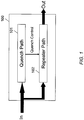
- FIG. 1 is a block diagram of a signal repeater 100 according to an embodiment of the present invention.
- the signal repeater 100 includes two paths: a quench path 101 and a repeater path 102. Both the quench path 101 and the repeater path 102 receive an input signal.
- the quench path 101 processes the input signal in the digital domain and performs emitter signal measurements on the input signal. If the measurements do not agree with preselected a priori information (e.g., predetermined characteristics), then the repeater path 102 is inhibited (or quenched). When the repeater path 102 is inhibited, the input signal is not repeated by the repeater path 102. In other words, the quench path 101 controls the repeater path 102 to selectively repeat the input signal.
- a priori information e.g., predetermined characteristics
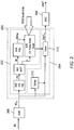
- FIG. 2 is a block diagram conceptually illustrating a signal repeater 200 according to an embodiment of the present invention.
- the signal repeater 200 includes a signal processing part 202 and a signal repeating part 204.
- An analog input signal IN e.g., an IF signal
- ADC analog-to-digital converter
- the digital signal IN D is processed by the signal processing part 202 and selectively repeated by the signal repeating part 204 as an output signal OUT D under the control of the signal processing part 202.
- the digital output signal OUT D can be converted back to an analog signal OUT by a suitable digital-to-analog converter (DAC) 208.
- DAC digital-to-analog converter
- the signal repeating part 204 has relatively low latency (e.g., a few nanoseconds), except for a delay 210, which will be described in more detail below.
- the signal processing part 202 performs various functions such as pulse detect and magnitude/frequency measurement functions, which introduce some latency (generally less than 30 nanoseconds in several embodiments).
- the signal processing part 202 is provided with a priori information (e.g., signal of interest tracking information, hereafter "SOI track info”) corresponding to the predetermined characteristics of the signals to be detected.
- SOI track info enables the signal processing part 202 to recognize signals from predetermined hostile emitters, and can be provided by any suitable sources such as an IRTG.
- the signal processing part 202 can determine whether the received signal IN comes from a friendly emitter or a hostile emitter.
- the signal processing part 202 is configured to control the signal repeating part 204 such that the input signal IN D is not repeated (i.e., inhibited or quenched) as the output signal OUT D at the output of the signal repeating part 204.
- the signal repeating part 204 includes a gate 212 that is controlled by the signal processing part 202.
- the signal processing part 202 outputs a control signal to enable or disable the gate 212.
- the gate 212 is enabled, the input signal IN D is repeated as the output signal OUT D . Therefore, when the received input signal IN is determined to be from a hostile emitter, the gate 212 is enabled so that the signal repeating part 204 can repeat the signal at the output thereof.
- the signal processing part 202 and the signal repeating part 204 will be described in more detail below.
- the signal processing part 202 includes an I/Q FIR 300, a magnitude/frequency (M/F) processor 302, a pulse detect logic (PDL) 304, and an EA pulse gate logic (PGL) 306.
- the I/Q FIR 300 e.g., a short non-decimated quadrature FIR
- the M/F processor 302 calculates the magnitude (M) and frequency (F) of the input signal from the I and Q signals.
- the PDL 304 receives the magnitude (M) and is configured to detect the presence of a signal pulse in the input signal IN that corresponds to a preselected pulse profile according to the SOI track info.
- the EA PGL 306 receives a pulse presence signal 304a, which indicates a signal pulse is detected, from the PDL 304 and the frequency (F) from the M/F processor 302.
- the pulse presence signal 304a and the frequency (F) are compared with a number of parameters (e.g., predicted pulse gate, jitter, frequency ranges, pulse amplitude, etc.) of the SOI track info to determine whether the input signal IN is from a friendly emitter or a hostile emitter.
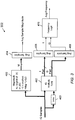
- FIG. 3 is a block diagram of the M/F processor 302 according to an embodiment of the present invention.
- the M/F processor 302 calculates the magnitude and frequency of the input signal IN from the I and Q samples of the signal.
- a magnitude calculation block 400 is configured to calculate the magnitude (M) of the input signal IN based on the IQ samples.
- An IQ multiply block 402 and a delay 403 are configured to perform conjugate multiply of a current IQ sample and a previous IQ sample. While FIG. 3 illustrates the input and output connections of the magnitude calculation block 400 and the IQ multiply block 402 with single lines for clarity, each of the single lines represents multiple branches (e.g., eight branches).
- , and S smallest of
- an average magnitude of the magnitudes of all the magnitude branches are calculated by an averaging circuit 404 to generate an average sample magnitude.
- the present invention is not limited to the above described estimation method, and other suitable estimation methods can be used.
- the input IQ samples include polyphase samples.
- respective I and Q parts of the polyphase samples are obtained.
- frequency of the input signal IN can be calculated from the values of the I and Q parts.
- the effective SNR can be improved for weak signals in the wide bandwidth by averaging multiple samples (e.g., eight samples) of the I parts and Q parts by averaging circuits 406 and 408, respectively.
- FIG. 4 is a block diagram conceptually illustrating the delay 210 according to an embodiment of the present invention.
- the delay 210 is implemented as a tap delay that includes multiple programmable delay blocks (500a-500n), scalers (K 1 -K n ), a combiner 502, and an adder 504.
- the delay 210 can be configured to add at least one clock latency to the signal repeating part 204 (see FIG. 2 ).
- the delay blocks (500a-500n) can be implemented with block RAMs (e.g., dual port RAM) to generate different delays or latencies that can be programmable.
- the scalers (K 1 -K n ) scale the signals from the delay blocks (500a-500n) according to their corresponding scaling factors (e.g., K 1 , K 2 ... K n ).
- the combiner 502 combines the scaled signals to generate a combined signal, which is added to a undelayed scaled (e.g., K 00 ) input signal to synthesize a realistic radar return from the single received pulse.
- the delay 210 includes sixteen delay blocks and sixteen scalers.
- the signal repeating part 204 can simulate realistic radar return signals that include individual reflections from various aspects of the targeted structure, which in turn occur at slightly different ranges or delays. Therefore, the programmable delay blocks (500a-500n) of the delay 210 can simulate structure reflections (relative delays) and their combinations.
- the present invention is not limited to the delay 210 as illustrated in FIG. 4 . In several embodiments, other suitable delay configurations may be used. In some embodiments, the delay 210 may not be included or used.
- the signal repeater 200 is described above in terms of a number of functional blocks and units, the signal repeater 200 is not limited thereto. To the contrary, the signal repeater 200 can include other parts or components that are commonly known in the art. Further, the various components of the signal repeater 200 can be implemented by a single circuit component (e.g., FPGA) or multiple circuit components operatively coupled together.
- the signal repeater 200 can be operated in two modes.
- a threat signal-of-interest SOI
- IRTG Tracker e.g., IRTG Tracker
- the tracker predicts the occurrence of future pulses of a pulse train.
- a Time Gate is generated that spans the time extent of a predicted future pulse. This Time Gate is utilized to pass signals that occur within the Time Gate and inhibit signals that occur outside the Time Gate.
- Typical radars exhibit a duty factor (portion of the total time the radar is transmitting) of less than one percent, so that the Time Gate can inhibit the preponderance of undesired signals.
- the radio frequency (RF) of the emitted signal is random so it cannot be predicted from the tracker.
- the RF is measured in the quench path when a pulse is detected, along with other parameters such as pulse width. These measurements on a received pulse are input to the EA Pulse Gate Logic where it is reconciled with the SOI Track Info. If the pulse measurements do not agree with the SOI Track Info, the repeater path is quenched (inhibited).
- the SOI is not tracked in time, so the pulse Time Gate is not available, and the measurements are wide open in time.
- This mode can be used for the situation where EA is performed on the first radar pulses emitted, i.e. pulses that occur before the IRTG can establish a track. Nonetheless, measurements are then performed on every received pulse.
- These pulse measurements are reconciled with SOI Track Info as before in mode one.
- the SOI Track Info also includes track information on all visible emitters that is used to inhibit jamming non-threat emitters, thus simplifying the recognition of a new threat SOI.
- FIG. 5 is a flowchart illustrating a method of operating a signal repeater according to an embodiment of the present invention.
- the signal repeater is operated to receive and convert an input signal into quadrature signals.
- the signal repeater is operated to process the quadrature signals to determine one or more characteristics of the input signal, and to compare the one or more characteristics of the input signal with a plurality of predetermined characteristics (e.g., a pulse gate, a frequency range, a pulse amplitude, etc.) to generate a comparison result.
- a plurality of predetermined characteristics e.g., a pulse gate, a frequency range, a pulse amplitude, etc.
- a digital wideband repeater with relatively low latency quench/inhibit functions as compared to the related art can be provided.
- Low latency signal parameter measurements and processing are facilitated by converting the signal of interest into corresponding I and Q parts by a suitable digital quadrature FIR.
- the frequency of the signal can be efficiently derived from a conjugate multiply which in turn is I/Q averaged to improve wideband SNR by about seven dB, prior to the arc-tangent calculation that requires at least six dB SNR.
- Magnitude of the signal is approximated and is also averaged. The calculated frequency is reconciled with an a priori input for possible quench action.
- the process or method can perform the sequence of actions in a different order. In another embodiment, the process or method can skip one or more of the actions. In other embodiments, one or more of the actions are performed simultaneously or concurrently. In some embodiments, additional actions can be performed.
Landscapes
- Engineering & Computer Science (AREA)
- Radar, Positioning & Navigation (AREA)
- Remote Sensing (AREA)
- Computer Networks & Wireless Communication (AREA)
- Physics & Mathematics (AREA)
- General Physics & Mathematics (AREA)
- Radar Systems Or Details Thereof (AREA)
- Radio Relay Systems (AREA)
- Digital Transmission Methods That Use Modulated Carrier Waves (AREA)
Applications Claiming Priority (2)
| Application Number | Priority Date | Filing Date | Title |
|---|---|---|---|
| US13/492,625 US8761233B2 (en) | 2012-06-08 | 2012-06-08 | Wideband low latency repeater and methods |
| PCT/US2013/034644 WO2013184232A1 (en) | 2012-06-08 | 2013-03-29 | Wideband low latency repeater and methods |
Publications (2)
| Publication Number | Publication Date |
|---|---|
| EP2859376A1 EP2859376A1 (en) | 2015-04-15 |
| EP2859376B1 true EP2859376B1 (en) | 2017-05-17 |
Family
ID=48142951
Family Applications (1)
| Application Number | Title | Priority Date | Filing Date |
|---|---|---|---|
| EP13717630.1A Active EP2859376B1 (en) | 2012-06-08 | 2013-03-29 | Wideband low latency repeater and methods |
Country Status (7)
| Country | Link |
|---|---|
| US (1) | US8761233B2 (cg-RX-API-DMAC7.html) |
| EP (1) | EP2859376B1 (cg-RX-API-DMAC7.html) |
| AU (1) | AU2013272236B2 (cg-RX-API-DMAC7.html) |
| DK (1) | DK2859376T3 (cg-RX-API-DMAC7.html) |
| IL (1) | IL235609B (cg-RX-API-DMAC7.html) |
| IN (1) | IN2014DN09380A (cg-RX-API-DMAC7.html) |
| WO (1) | WO2013184232A1 (cg-RX-API-DMAC7.html) |
Families Citing this family (3)
| Publication number | Priority date | Publication date | Assignee | Title |
|---|---|---|---|---|
| US9553620B2 (en) * | 2014-07-16 | 2017-01-24 | Raytheon Company | Signal detection and characterization |
| FR3056763B1 (fr) * | 2016-09-26 | 2018-10-26 | Thales | Dispositif de generation d'un signal porteur continu a partir d'un signal impulsionnel de reference |
| US10411744B1 (en) | 2018-10-11 | 2019-09-10 | Ratheon Company | Waveform transformation and reconstruction |
Family Cites Families (9)
| Publication number | Priority date | Publication date | Assignee | Title |
|---|---|---|---|---|
| US4318183A (en) | 1978-12-22 | 1982-03-02 | Raytheon Company | Multiple channel digital memory system |
| US5828705A (en) * | 1996-02-01 | 1998-10-27 | Kroeger; Brian W. | Carrier tracking technique and apparatus having automatic flywheel/tracking/reacquisition control and extended signal to noise ratio |
| US6081822A (en) * | 1998-03-11 | 2000-06-27 | Agilent Technologies, Inc. | Approximating signal power and noise power in a system |
| US6678320B1 (en) * | 1998-08-31 | 2004-01-13 | Qualcomm, Incorporated | Efficient finite impulse response filter implementation for CDMA waveform generation |
| EP1039716B1 (en) | 1999-03-25 | 2003-04-16 | Kabushiki Kaisha Toshiba | OFDM transmission signal repeater and receiver |
| US6791489B1 (en) | 2001-03-12 | 2004-09-14 | Northrop Grumman Corporation | Radio tag for LFM radar |
| US6624780B1 (en) | 2002-10-02 | 2003-09-23 | The United States Of America As Represented By The Secretary Of The Navy | False target radar image generator for countering wideband imaging radars |
| IL178910A (en) * | 2006-10-26 | 2008-04-13 | Rst Reut Systems & Advanced Te | Airborne bait that transmits radio frequencies (RF) and a method of deceiving radar-guided missiles by exploiting it |
| US7835463B2 (en) | 2007-04-26 | 2010-11-16 | The United States Of America As Represented By The Secretary Of The Department Of The Navy | Digital radio frequency memory |
-
2012
- 2012-06-08 US US13/492,625 patent/US8761233B2/en active Active
-
2013
- 2013-03-29 WO PCT/US2013/034644 patent/WO2013184232A1/en not_active Ceased
- 2013-03-29 EP EP13717630.1A patent/EP2859376B1/en active Active
- 2013-03-29 IN IN9380DEN2014 patent/IN2014DN09380A/en unknown
- 2013-03-29 DK DK13717630.1T patent/DK2859376T3/en active
- 2013-03-29 AU AU2013272236A patent/AU2013272236B2/en active Active
-
2014
- 2014-11-10 IL IL235609A patent/IL235609B/en active IP Right Grant
Also Published As
| Publication number | Publication date |
|---|---|
| EP2859376A1 (en) | 2015-04-15 |
| IL235609B (en) | 2018-06-28 |
| WO2013184232A1 (en) | 2013-12-12 |
| US20130329771A1 (en) | 2013-12-12 |
| US8761233B2 (en) | 2014-06-24 |
| AU2013272236A1 (en) | 2014-11-20 |
| IL235609A0 (en) | 2015-01-29 |
| IN2014DN09380A (cg-RX-API-DMAC7.html) | 2015-07-17 |
| DK2859376T3 (en) | 2017-09-04 |
| AU2013272236B2 (en) | 2016-04-07 |
Similar Documents
| Publication | Publication Date | Title |
|---|---|---|
| US20240192349A1 (en) | Radar apparatus and radar method | |
| JP6818541B2 (ja) | レーダ装置および測位方法 | |
| CN110031805B (zh) | 雷达装置 | |
| Malanowski | Detection and parameter estimation of manoeuvring targets with passive bistatic radar | |
| WO2013179941A1 (ja) | レーダ装置 | |
| US20200166625A1 (en) | Wideband radar systems, apparatuses, and methods | |
| JPWO2007020704A1 (ja) | 目標物検出方法及び目標物検出装置 | |
| Zwanetski et al. | Waveform design for FMCW MIMO radar based on frequency division | |
| EP2859376B1 (en) | Wideband low latency repeater and methods | |
| KR101967812B1 (ko) | 가중치 적용 칼만 필터를 이용한 레이더 신호 처리 장치 및 그를 이용한 표적 검출 시스템 | |
| EP3399334B1 (en) | Object detecting device and sensor device | |
| RU2504799C2 (ru) | Имитатор радиолокационной цели при зондировании преимущественно длительными сигналами | |
| Guetlein et al. | Calibration strategy for a TDM FMCW MIMO radar system | |
| JP7345099B2 (ja) | レーダ装置、及び、レーダ方法 | |
| Borowiec et al. | Accelerating rocket detection using passive bistatic radar | |
| Zainuddin et al. | Performance of MIMO FMCW radar in detecting small vessels | |
| Prodi et al. | Motion compensation for a frequency stepped radar | |
| Ganis et al. | A system concept for a 3D real-time OFDM MIMO radar for flying platforms | |
| KR20150135734A (ko) | 선형 주파수 변조 신호와 잡음 신호를 이용한 레이더 및 이의 제어 방법 | |
| Madhupriya et al. | Implementation of compressed wave pulsed radar altimeter in signal processing | |
| JP5485213B2 (ja) | パルスレーダ装置及びその制御方法 | |
| Gilpin et al. | Real-Time Multiple Input Multiple Output (MIMO) Radar Using Software Defined Radio | |
| EP3742196B1 (en) | Radar device | |
| Kohler et al. | Empirical calibration coefficient estimation in the context of multi-functional rf systems | |
| Gogineni et al. | Ambiguity function analysis for passive multistatic radar using UMTS signals |
Legal Events
| Date | Code | Title | Description |
|---|---|---|---|
| PUAI | Public reference made under article 153(3) epc to a published international application that has entered the european phase |
Free format text: ORIGINAL CODE: 0009012 |
|
| 17P | Request for examination filed |
Effective date: 20141223 |
|
| AK | Designated contracting states |
Kind code of ref document: A1 Designated state(s): AL AT BE BG CH CY CZ DE DK EE ES FI FR GB GR HR HU IE IS IT LI LT LU LV MC MK MT NL NO PL PT RO RS SE SI SK SM TR |
|
| AX | Request for extension of the european patent |
Extension state: BA ME |
|
| DAX | Request for extension of the european patent (deleted) | ||
| 17Q | First examination report despatched |
Effective date: 20160308 |
|
| GRAP | Despatch of communication of intention to grant a patent |
Free format text: ORIGINAL CODE: EPIDOSNIGR1 |
|
| INTG | Intention to grant announced |
Effective date: 20161202 |
|
| GRAS | Grant fee paid |
Free format text: ORIGINAL CODE: EPIDOSNIGR3 |
|
| GRAA | (expected) grant |
Free format text: ORIGINAL CODE: 0009210 |
|
| AK | Designated contracting states |
Kind code of ref document: B1 Designated state(s): AL AT BE BG CH CY CZ DE DK EE ES FI FR GB GR HR HU IE IS IT LI LT LU LV MC MK MT NL NO PL PT RO RS SE SI SK SM TR |
|
| REG | Reference to a national code |
Ref country code: GB Ref legal event code: FG4D |
|
| REG | Reference to a national code |
Ref country code: CH Ref legal event code: EP |
|
| REG | Reference to a national code |
Ref country code: IE Ref legal event code: FG4D |
|
| REG | Reference to a national code |
Ref country code: AT Ref legal event code: REF Ref document number: 894947 Country of ref document: AT Kind code of ref document: T Effective date: 20170615 |
|
| REG | Reference to a national code |
Ref country code: DE Ref legal event code: R096 Ref document number: 602013021239 Country of ref document: DE |
|
| REG | Reference to a national code |
Ref country code: DK Ref legal event code: T3 Effective date: 20170828 |
|
| REG | Reference to a national code |
Ref country code: NL Ref legal event code: MP Effective date: 20170517 |
|
| REG | Reference to a national code |
Ref country code: LT Ref legal event code: MG4D |
|
| REG | Reference to a national code |
Ref country code: AT Ref legal event code: MK05 Ref document number: 894947 Country of ref document: AT Kind code of ref document: T Effective date: 20170517 |
|
| PG25 | Lapsed in a contracting state [announced via postgrant information from national office to epo] |
Ref country code: NO Free format text: LAPSE BECAUSE OF FAILURE TO SUBMIT A TRANSLATION OF THE DESCRIPTION OR TO PAY THE FEE WITHIN THE PRESCRIBED TIME-LIMIT Effective date: 20170817 Ref country code: FI Free format text: LAPSE BECAUSE OF FAILURE TO SUBMIT A TRANSLATION OF THE DESCRIPTION OR TO PAY THE FEE WITHIN THE PRESCRIBED TIME-LIMIT Effective date: 20170517 Ref country code: LT Free format text: LAPSE BECAUSE OF FAILURE TO SUBMIT A TRANSLATION OF THE DESCRIPTION OR TO PAY THE FEE WITHIN THE PRESCRIBED TIME-LIMIT Effective date: 20170517 Ref country code: GR Free format text: LAPSE BECAUSE OF FAILURE TO SUBMIT A TRANSLATION OF THE DESCRIPTION OR TO PAY THE FEE WITHIN THE PRESCRIBED TIME-LIMIT Effective date: 20170818 Ref country code: HR Free format text: LAPSE BECAUSE OF FAILURE TO SUBMIT A TRANSLATION OF THE DESCRIPTION OR TO PAY THE FEE WITHIN THE PRESCRIBED TIME-LIMIT Effective date: 20170517 Ref country code: AT Free format text: LAPSE BECAUSE OF FAILURE TO SUBMIT A TRANSLATION OF THE DESCRIPTION OR TO PAY THE FEE WITHIN THE PRESCRIBED TIME-LIMIT Effective date: 20170517 Ref country code: ES Free format text: LAPSE BECAUSE OF FAILURE TO SUBMIT A TRANSLATION OF THE DESCRIPTION OR TO PAY THE FEE WITHIN THE PRESCRIBED TIME-LIMIT Effective date: 20170517 |
|
| PG25 | Lapsed in a contracting state [announced via postgrant information from national office to epo] |
Ref country code: NL Free format text: LAPSE BECAUSE OF FAILURE TO SUBMIT A TRANSLATION OF THE DESCRIPTION OR TO PAY THE FEE WITHIN THE PRESCRIBED TIME-LIMIT Effective date: 20170517 Ref country code: IS Free format text: LAPSE BECAUSE OF FAILURE TO SUBMIT A TRANSLATION OF THE DESCRIPTION OR TO PAY THE FEE WITHIN THE PRESCRIBED TIME-LIMIT Effective date: 20170917 Ref country code: BG Free format text: LAPSE BECAUSE OF FAILURE TO SUBMIT A TRANSLATION OF THE DESCRIPTION OR TO PAY THE FEE WITHIN THE PRESCRIBED TIME-LIMIT Effective date: 20170817 Ref country code: LV Free format text: LAPSE BECAUSE OF FAILURE TO SUBMIT A TRANSLATION OF THE DESCRIPTION OR TO PAY THE FEE WITHIN THE PRESCRIBED TIME-LIMIT Effective date: 20170517 Ref country code: SE Free format text: LAPSE BECAUSE OF FAILURE TO SUBMIT A TRANSLATION OF THE DESCRIPTION OR TO PAY THE FEE WITHIN THE PRESCRIBED TIME-LIMIT Effective date: 20170517 Ref country code: RS Free format text: LAPSE BECAUSE OF FAILURE TO SUBMIT A TRANSLATION OF THE DESCRIPTION OR TO PAY THE FEE WITHIN THE PRESCRIBED TIME-LIMIT Effective date: 20170517 Ref country code: PL Free format text: LAPSE BECAUSE OF FAILURE TO SUBMIT A TRANSLATION OF THE DESCRIPTION OR TO PAY THE FEE WITHIN THE PRESCRIBED TIME-LIMIT Effective date: 20170517 |
|
| PG25 | Lapsed in a contracting state [announced via postgrant information from national office to epo] |
Ref country code: SK Free format text: LAPSE BECAUSE OF FAILURE TO SUBMIT A TRANSLATION OF THE DESCRIPTION OR TO PAY THE FEE WITHIN THE PRESCRIBED TIME-LIMIT Effective date: 20170517 Ref country code: CZ Free format text: LAPSE BECAUSE OF FAILURE TO SUBMIT A TRANSLATION OF THE DESCRIPTION OR TO PAY THE FEE WITHIN THE PRESCRIBED TIME-LIMIT Effective date: 20170517 Ref country code: EE Free format text: LAPSE BECAUSE OF FAILURE TO SUBMIT A TRANSLATION OF THE DESCRIPTION OR TO PAY THE FEE WITHIN THE PRESCRIBED TIME-LIMIT Effective date: 20170517 Ref country code: RO Free format text: LAPSE BECAUSE OF FAILURE TO SUBMIT A TRANSLATION OF THE DESCRIPTION OR TO PAY THE FEE WITHIN THE PRESCRIBED TIME-LIMIT Effective date: 20170517 |
|
| REG | Reference to a national code |
Ref country code: DE Ref legal event code: R097 Ref document number: 602013021239 Country of ref document: DE |
|
| REG | Reference to a national code |
Ref country code: FR Ref legal event code: PLFP Year of fee payment: 6 |
|
| PG25 | Lapsed in a contracting state [announced via postgrant information from national office to epo] |
Ref country code: SM Free format text: LAPSE BECAUSE OF FAILURE TO SUBMIT A TRANSLATION OF THE DESCRIPTION OR TO PAY THE FEE WITHIN THE PRESCRIBED TIME-LIMIT Effective date: 20170517 Ref country code: IT Free format text: LAPSE BECAUSE OF FAILURE TO SUBMIT A TRANSLATION OF THE DESCRIPTION OR TO PAY THE FEE WITHIN THE PRESCRIBED TIME-LIMIT Effective date: 20170517 |
|
| PLBE | No opposition filed within time limit |
Free format text: ORIGINAL CODE: 0009261 |
|
| STAA | Information on the status of an ep patent application or granted ep patent |
Free format text: STATUS: NO OPPOSITION FILED WITHIN TIME LIMIT |
|
| 26N | No opposition filed |
Effective date: 20180220 |
|
| PG25 | Lapsed in a contracting state [announced via postgrant information from national office to epo] |
Ref country code: SI Free format text: LAPSE BECAUSE OF FAILURE TO SUBMIT A TRANSLATION OF THE DESCRIPTION OR TO PAY THE FEE WITHIN THE PRESCRIBED TIME-LIMIT Effective date: 20170517 |
|
| REG | Reference to a national code |
Ref country code: CH Ref legal event code: PL |
|
| PG25 | Lapsed in a contracting state [announced via postgrant information from national office to epo] |
Ref country code: MC Free format text: LAPSE BECAUSE OF FAILURE TO SUBMIT A TRANSLATION OF THE DESCRIPTION OR TO PAY THE FEE WITHIN THE PRESCRIBED TIME-LIMIT Effective date: 20170517 |
|
| REG | Reference to a national code |
Ref country code: BE Ref legal event code: MM Effective date: 20180331 |
|
| REG | Reference to a national code |
Ref country code: IE Ref legal event code: MM4A |
|
| PG25 | Lapsed in a contracting state [announced via postgrant information from national office to epo] |
Ref country code: LU Free format text: LAPSE BECAUSE OF NON-PAYMENT OF DUE FEES Effective date: 20180329 |
|
| PG25 | Lapsed in a contracting state [announced via postgrant information from national office to epo] |
Ref country code: IE Free format text: LAPSE BECAUSE OF NON-PAYMENT OF DUE FEES Effective date: 20180329 |
|
| PG25 | Lapsed in a contracting state [announced via postgrant information from national office to epo] |
Ref country code: LI Free format text: LAPSE BECAUSE OF NON-PAYMENT OF DUE FEES Effective date: 20180331 Ref country code: CH Free format text: LAPSE BECAUSE OF NON-PAYMENT OF DUE FEES Effective date: 20180331 Ref country code: BE Free format text: LAPSE BECAUSE OF NON-PAYMENT OF DUE FEES Effective date: 20180331 |
|
| PG25 | Lapsed in a contracting state [announced via postgrant information from national office to epo] |
Ref country code: MT Free format text: LAPSE BECAUSE OF NON-PAYMENT OF DUE FEES Effective date: 20180329 |
|
| PG25 | Lapsed in a contracting state [announced via postgrant information from national office to epo] |
Ref country code: TR Free format text: LAPSE BECAUSE OF FAILURE TO SUBMIT A TRANSLATION OF THE DESCRIPTION OR TO PAY THE FEE WITHIN THE PRESCRIBED TIME-LIMIT Effective date: 20170517 |
|
| PG25 | Lapsed in a contracting state [announced via postgrant information from national office to epo] |
Ref country code: PT Free format text: LAPSE BECAUSE OF FAILURE TO SUBMIT A TRANSLATION OF THE DESCRIPTION OR TO PAY THE FEE WITHIN THE PRESCRIBED TIME-LIMIT Effective date: 20170517 |
|
| PG25 | Lapsed in a contracting state [announced via postgrant information from national office to epo] |
Ref country code: MK Free format text: LAPSE BECAUSE OF NON-PAYMENT OF DUE FEES Effective date: 20170517 Ref country code: HU Free format text: LAPSE BECAUSE OF FAILURE TO SUBMIT A TRANSLATION OF THE DESCRIPTION OR TO PAY THE FEE WITHIN THE PRESCRIBED TIME-LIMIT; INVALID AB INITIO Effective date: 20130329 Ref country code: CY Free format text: LAPSE BECAUSE OF FAILURE TO SUBMIT A TRANSLATION OF THE DESCRIPTION OR TO PAY THE FEE WITHIN THE PRESCRIBED TIME-LIMIT Effective date: 20170517 |
|
| PG25 | Lapsed in a contracting state [announced via postgrant information from national office to epo] |
Ref country code: AL Free format text: LAPSE BECAUSE OF FAILURE TO SUBMIT A TRANSLATION OF THE DESCRIPTION OR TO PAY THE FEE WITHIN THE PRESCRIBED TIME-LIMIT Effective date: 20170517 |
|
| P01 | Opt-out of the competence of the unified patent court (upc) registered |
Effective date: 20230530 |
|
| PGFP | Annual fee paid to national office [announced via postgrant information from national office to epo] |
Ref country code: GB Payment date: 20260220 Year of fee payment: 14 |
|
| PGFP | Annual fee paid to national office [announced via postgrant information from national office to epo] |
Ref country code: DK Payment date: 20260219 Year of fee payment: 14 Ref country code: DE Payment date: 20260219 Year of fee payment: 14 |
|
| PGFP | Annual fee paid to national office [announced via postgrant information from national office to epo] |
Ref country code: FR Payment date: 20260219 Year of fee payment: 14 |