EP2859285B1 - Machine for making ice particularly for a counter for displaying goods - Google Patents
Machine for making ice particularly for a counter for displaying goods Download PDFInfo
- Publication number
- EP2859285B1 EP2859285B1 EP13728150.7A EP13728150A EP2859285B1 EP 2859285 B1 EP2859285 B1 EP 2859285B1 EP 13728150 A EP13728150 A EP 13728150A EP 2859285 B1 EP2859285 B1 EP 2859285B1
- Authority
- EP
- European Patent Office
- Prior art keywords
- machine
- ice
- dispensing means
- counter
- making ice
- Prior art date
- Legal status (The legal status is an assumption and is not a legal conclusion. Google has not performed a legal analysis and makes no representation as to the accuracy of the status listed.)
- Active
Links
Images



Classifications
-
- F—MECHANICAL ENGINEERING; LIGHTING; HEATING; WEAPONS; BLASTING
- F25—REFRIGERATION OR COOLING; COMBINED HEATING AND REFRIGERATION SYSTEMS; HEAT PUMP SYSTEMS; MANUFACTURE OR STORAGE OF ICE; LIQUEFACTION SOLIDIFICATION OF GASES
- F25C—PRODUCING, WORKING OR HANDLING ICE
- F25C5/00—Working or handling ice
- F25C5/18—Storing ice
- F25C5/182—Ice bins therefor
- F25C5/187—Ice bins therefor with ice level sensing means
-
- F—MECHANICAL ENGINEERING; LIGHTING; HEATING; WEAPONS; BLASTING
- F25—REFRIGERATION OR COOLING; COMBINED HEATING AND REFRIGERATION SYSTEMS; HEAT PUMP SYSTEMS; MANUFACTURE OR STORAGE OF ICE; LIQUEFACTION SOLIDIFICATION OF GASES
- F25C—PRODUCING, WORKING OR HANDLING ICE
- F25C1/00—Producing ice
- F25C1/04—Producing ice by using stationary moulds
- F25C1/06—Producing ice by using stationary moulds open or openable at both ends
Definitions
- the present invention relates to a machine for making ice particularly for a counter for displaying goods.
- Machines for making ice have been present on the market for some time, of the kind comprising a tubular conduit for the formation of ice, coated by a refrigeration unit evaporator and having internally a screw conveyor for moving the ice towards its delivery end with which a ring nut is associated having drawing holes.
- the machines to which reference is made are adapted to produce ice in small pieces, known in technical jargon as “nuggets” or “flakers” or in granules or cubes.
- the ice used for displaying products, particularly fish products can be a source of secondary contamination for such products and the accumulation of contaminants and pollutants in the ice that is placed in a ground level container can increase the hygiene risk.
- a disadvantage of these machines is their difficult application to a counter for displaying goods having a substantial height development, since the ice is only distributed in small areas of the counter, hence obliging the operator to intervene manually to uniformly distribute the ice onto the display surface, with the risk of increasing the contamination of the ice and consequently the products that will be displayed thereon.
- the technical task of the present invention is, therefore, to provide a machine for making ice particularly for a counter for displaying goods which obviates the above-described technical drawbacks.
- an object of the invention is to provide a machine for making ice particularly for a counter for displaying goods, which allows ice to be dispensed so as to cover a larger surface of the counter automatically, eliminating the operator's manual intervention.
- Another object of the invention is to provide a machine for making ice which allows greater flexibility of use, allowing the operator the possibility to take the ice out of other points on the machine, also while the ice is being dispensed onto the counter.
- Another object of the invention is to provide a machine for making ice that can be associated with a counter for displaying goods without obstructing the passage for personnel.
- Another object of the present invention is to provide a machine for making ice that is structurally simple and cheap.
- a machine for making ice of this type is known from US patent n.6324855 B1 and comprises its own container of ice which collects the ice that is produced by the dispensing means.
- the machine for making ice comprises a sliding device of the cylinders of ice apt to subject the cylinders of ice to a propulsion force acting in combination with the force of gravity so as to distribute the cylinders of ice over a larger surface area of the counter.
- the sliding device is a slide having an initial straight portion and an end portion having a lower inclination with respect to said initial straight portion.
- the end portion has a curvilinear run.
- the slide has a channel-like conformation defined by two lateral walls closed from above.
- the proximity sensor is configured and arranged so as to detect the minimum distance between the end portion of the slide and the accumulation of the cylinders of ice on the counter.
- the first sensor is positioned above the slide. More in particular, the machine for making ice comprises a safety sensor located on the lateral walls upstream from the first sensor.
- the machine for making ice comprises second dispensing means positioned on one side of the machine accessible to the operator.
- first dispensing means and the second dispensing means are angularly staggered.
- the machine for making ice comprises selective opening means of said first or second dispensing means.
- the selection means comprise an operating lever of a shutter having an opening for the passage of the cylinders of ice.
- the lever is mobile between a first working position in which the opening lines up selectively with the first dispensing means, and a second working position in which the opening lines up selectively with the second dispensing means.
- the lever is positioned on a lateral boundary wall of the machine.
- the machine for making ice comprises a shovel adapted to direct the cylinders of ice that are formed by the machine towards the first or second dispensing means.
- the machine has a front boundary wall facing the counter on which said first dispensing means are located and at least one lateral boundary wall on which the second dispensing means are located.
- the machine has a back boundary wall, on the opposite side to the front boundary wall, tapered in order to reduce the overall dimensions.
- the machine 1 is in particular intended for the production of "nuggets" which means cylinders of ice of the desired diameter.
- the machine 1 comprises a gas inlet conduit 53 which takes the gas to an expansion valve 2 connected to the evaporator 3 having internally a screw conveyor 8 for moving the ice towards the ice-breaking device 10 from which through a plurality of holes 11 the "nuggets" of ice 121 are formed.
- the machine 1 further comprises a refrigerating adjustment valve 5 and a shut-off valve 6, positioned on the gas inlet conduit 53 which prevents the gas returning backwards.
- the machine 1 is further equipped with a basin 22 in which a float is provided for checking the water level, which must always be constant for the correct operation of the machine 1.
- the supply of water to the basin 22 takes place by means of a water supply conduit 21.
- the machine 1 is also provided with a conduit 20 for discharging excess water. From the basin 22 the water is transported to the evaporator 3 by means of the connection channel 23.
- the cylinders of ice that are formed through the plurality of holes 11 are conveyed selectively, by means of a shovel 12 fixed through a screw 13 to the screw conveyor 8, towards the first dispensing means 16 or the second dispensing means 50.
- the first dispensing means 16 comprise a sliding device adapted to subject the cylinders of ice 121 to a propulsion force acting in combination with the force of gravity so as to distribute the cylinders of ice over a wider surface area of the counter 120.
- This sliding device is a slide 17 having an initial straight portion 108 and an end portion with a curvilinear run 107 having a lower inclination with respect to the initial straight portion 108.
- the slide has a channel-like conformation defined by two lateral walls 111 closed from above.
- the cylinders of ice that are formed and that slide along the slide 17, are distributed, by means of the propulsion force generated by the end portion 107 having a curvilinear run of the slide 17 onto a larger surface area of the counter 120 with respect to the surface area that the cylinders of ice would occupy if they were only subject to the force of gravity.
- first dispensing means are associated with a proximity sensor 15 and a safety sensor 14.
- the proximity sensor 15, located above the slide 17, detects the quantity of ice 121 accumulated on the counter 120, causing the machine to stop in the event of excessive accumulation of ice.
- the proximity sensor 15 detects the minimum distance between the end portion having a curvilinear run (107) of the slide (17) and the accumulation of the cylinders of ice (121) on the counter (120).
- the machine 1 also comprises the safety sensor 14 which is positioned on the lateral walls 111 of the slide 17 upstream from the proximity sensor 15.
- the presence of the safety sensor 14 ensures the correct operation of the machine for making ice 1.
- the safety sensor 14 is an optical reader that detects the cylinders of ice 121 moving along the slide.
- the machine for making ice 1 further comprises second dispensing means 50 positioned on one side of the machine 1 accessible to the operator.
- said second dispensing means 50 allows greater operating flexibility of the machine for making ice according to the present invention, since it allows the operator to be able to exploit said second dispensing means 50 for the manual collection of the ice by means of a container, hence avoiding the need to take out and therefore partially contaminate the ice that falls onto the counter through the first dispensing means 16 or even having to move the machine 1, which would be particularly problematic and/or impractical if the machine for making ice were fixed to the counter 120.
- the machine 1 advantageously comprises selective opening means of said first or second dispensing means 16, 50.
- the selective opening means comprise an actuating lever 51 of a shutter 55 having an opening 56 for the passage of the cylinders of ice that are formed.
- the lever 51 is mobile between a first working position and a second working position.
- the cylinders of ice that are formed are thus conveyed by means of the shovel 12 selectively towards the slide 17 in order to be dispensed onto the counter 120.
- the machine for making ice 1 is fixed to the counter 120 and has an outer casing comprising a front boundary wall 125, two lateral boundary walls 127 and a back boundary wall 124.
- the first dispensing means 16 are located on the front boundary wall 125 overlooking the counter.
- the second dispensing means 50 are located on one of the two lateral boundary walls 127 of the machine 1.
- the front boundary wall and the two lateral boundary walls 127 are arranged so as to form a 90° angle between them and in this way the first means 16 and the second means 50 are angularly staggered.
- the machine 1 has a back portion 124, on the opposite side to the front portion 125, tapered so as to reduce the dimensions of the machine 1 and facilitate the passage of the operator.
- a timer 33 is further envisaged, apt to set the operating times of the machine 1.
- the materials used, as well as the dimensions, may in practice be of any type according to requirements and the state of the art.
Landscapes
- Engineering & Computer Science (AREA)
- Physics & Mathematics (AREA)
- Mechanical Engineering (AREA)
- Thermal Sciences (AREA)
- General Engineering & Computer Science (AREA)
- Production, Working, Storing, Or Distribution Of Ice (AREA)
- Carbon And Carbon Compounds (AREA)
- Manufacture Or Reproduction Of Printing Formes (AREA)
- Preparing Plates And Mask In Photomechanical Process (AREA)
Description
- The present invention relates to a machine for making ice particularly for a counter for displaying goods.
- Machines for making ice have been present on the market for some time, of the kind comprising a tubular conduit for the formation of ice, coated by a refrigeration unit evaporator and having internally a screw conveyor for moving the ice towards its delivery end with which a ring nut is associated having drawing holes.
- In particular, the machines to which reference is made are adapted to produce ice in small pieces, known in technical jargon as "nuggets" or "flakers" or in granules or cubes.
- It is well known that the ice used for displaying products, particularly fish products, can be a source of secondary contamination for such products and the accumulation of contaminants and pollutants in the ice that is placed in a ground level container can increase the hygiene risk.
- A disadvantage of these machines is their difficult application to a counter for displaying goods having a substantial height development, since the ice is only distributed in small areas of the counter, hence obliging the operator to intervene manually to uniformly distribute the ice onto the display surface, with the risk of increasing the contamination of the ice and consequently the products that will be displayed thereon.
- Furthermore, the ice only falling into small areas of the counter leads to fast accumulation of ice which quickly reaches the dispensing nozzle of the machine dispenser causing blockages and therefore malfunctioning or even blocking of the machine itself.
- The technical task of the present invention is, therefore, to provide a machine for making ice particularly for a counter for displaying goods which obviates the above-described technical drawbacks.
- Within the scope of this technical task an object of the invention is to provide a machine for making ice particularly for a counter for displaying goods, which allows ice to be dispensed so as to cover a larger surface of the counter automatically, eliminating the operator's manual intervention.
- Another object of the invention is to provide a machine for making ice which allows greater flexibility of use, allowing the operator the possibility to take the ice out of other points on the machine, also while the ice is being dispensed onto the counter.
- Another object of the invention is to provide a machine for making ice that can be associated with a counter for displaying goods without obstructing the passage for personnel.
- Another object of the present invention is to provide a machine for making ice that is structurally simple and cheap.
- The technical task, as well as these and other objects, according to the present invention, are reached by providing a machine for making ice according to
claim 1. - A machine for making ice of this type is known from
US patent n.6324855 B1 and comprises its own container of ice which collects the ice that is produced by the dispensing means. - In this ice machine the ice falls into the container under the force of gravity alone, and therefore with a substantially vertical path with respect to the collection container of ice and the proximity sensor is positioned in the collection container of ice.
- According to the invention, the machine for making ice comprises a sliding device of the cylinders of ice apt to subject the cylinders of ice to a propulsion force acting in combination with the force of gravity so as to distribute the cylinders of ice over a larger surface area of the counter.
- In particular, the sliding device is a slide having an initial straight portion and an end portion having a lower inclination with respect to said initial straight portion.
- In particular, the end portion has a curvilinear run.
- Preferably the slide has a channel-like conformation defined by two lateral walls closed from above.
- According to the invention, the proximity sensor is configured and arranged so as to detect the minimum distance between the end portion of the slide and the accumulation of the cylinders of ice on the counter.
- According to the invention, the first sensor is positioned above the slide. More in particular, the machine for making ice comprises a safety sensor located on the lateral walls upstream from the first sensor.
- Preferably the machine for making ice comprises second dispensing means positioned on one side of the machine accessible to the operator.
- Preferably the first dispensing means and the second dispensing means are angularly staggered.
- Preferably the machine for making ice comprises selective opening means of said first or second dispensing means.
- Preferably the selection means comprise an operating lever of a shutter having an opening for the passage of the cylinders of ice.
- In particular, the lever is mobile between a first working position in which the opening lines up selectively with the first dispensing means, and a second working position in which the opening lines up selectively with the second dispensing means.
- Preferably the lever is positioned on a lateral boundary wall of the machine. Preferably the machine for making ice comprises a shovel adapted to direct the cylinders of ice that are formed by the machine towards the first or second dispensing means.
- More in particular, the machine has a front boundary wall facing the counter on which said first dispensing means are located and at least one lateral boundary wall on which the second dispensing means are located.
- Preferably the machine has a back boundary wall, on the opposite side to the front boundary wall, tapered in order to reduce the overall dimensions.
- Further characteristics and advantages of the invention will more fully emerge from the description of a preferred but not exclusive embodiment of the machine for making ice according to the invention, illustrated by way of non-limiting example in the accompanying figures of the drawings, in which:
-
Figure 1 shows a broken away perspective view of the machine associated with the counter. -
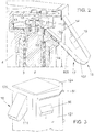
Figure 2 shows a section view along the line 1-1 of a detail of the machine ofFigure 1 , wherein the first dispensing means, the proximity sensor and the optical sensor are illustrated. -
Figure 3 shows a partial perspective view of the machine ofFigure 1 wherein the first dispensing means, the second dispensing means and the selection means, which selectively determine the dispensing of the cylinders of ice through the second dispensing means, are shown. -
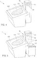
Figure 4 shows a perspective view of the machine ofFigure 1 wherein the lever is in the first working position and the ice is dispensed by the first dispensing means. -
Figure 5 shows a perspective view of the machine ofFigure 1 wherein the lever is in the second working position and the ice is dispensed by the second dispensing means. -
Figure 6 shows a perspective view of the inside of the machine ofFigure 1 wherein the lever associated with the mobile circular element is shown as the opening of the mobile circular element matches up with the first dispensing means and the movement of the shovel transports the cylinders of ice towards the first dispensing means. -
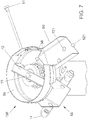
Figure 7 shows a perspective view of the inside of the machine ofFigure 1 wherein the lever associated with the mobile circular element is shown as the opening of the mobile circular element matches up with the second dispensing means and the movement of the shovel transports the cylinders of ice towards the second dispensing means. -
Figure 8 shows a broken away perspective view wherein the essential components of the machine are illustrated. - With reference to the figures mentioned, a machine for making ice is shown indicated overall with the
reference number 1. - The
machine 1 is in particular intended for the production of "nuggets" which means cylinders of ice of the desired diameter. - The
machine 1 comprises agas inlet conduit 53 which takes the gas to anexpansion valve 2 connected to theevaporator 3 having internally ascrew conveyor 8 for moving the ice towards the ice-breakingdevice 10 from which through a plurality ofholes 11 the "nuggets" ofice 121 are formed. - From the
evaporator 3 the gas is then conveyed into thedischarge pipe 4. - The
machine 1 further comprises a refrigeratingadjustment valve 5 and a shut-off valve 6, positioned on thegas inlet conduit 53 which prevents the gas returning backwards. - The
machine 1 is further equipped with abasin 22 in which a float is provided for checking the water level, which must always be constant for the correct operation of themachine 1. - The supply of water to the
basin 22 takes place by means of awater supply conduit 21. - The
machine 1 is also provided with aconduit 20 for discharging excess water. From thebasin 22 the water is transported to theevaporator 3 by means of theconnection channel 23. - The cylinders of ice that are formed through the plurality of
holes 11 are conveyed selectively, by means of ashovel 12 fixed through ascrew 13 to thescrew conveyor 8, towards the first dispensing means 16 or the second dispensing means 50. - According to the invention, the first dispensing means 16 comprise a sliding device adapted to subject the cylinders of
ice 121 to a propulsion force acting in combination with the force of gravity so as to distribute the cylinders of ice over a wider surface area of thecounter 120. - This sliding device is a
slide 17 having an initialstraight portion 108 and an end portion with acurvilinear run 107 having a lower inclination with respect to the initialstraight portion 108. - The slide has a channel-like conformation defined by two
lateral walls 111 closed from above. - The cylinders of ice that are formed and that slide along the
slide 17, are distributed, by means of the propulsion force generated by theend portion 107 having a curvilinear run of theslide 17 onto a larger surface area of thecounter 120 with respect to the surface area that the cylinders of ice would occupy if they were only subject to the force of gravity. - Furthermore the first dispensing means are associated with a
proximity sensor 15 and asafety sensor 14. - The
proximity sensor 15, located above theslide 17, detects the quantity ofice 121 accumulated on thecounter 120, causing the machine to stop in the event of excessive accumulation of ice. - In particular, the
proximity sensor 15 detects the minimum distance between the end portion having a curvilinear run (107) of the slide (17) and the accumulation of the cylinders of ice (121) on the counter (120). - For increased safety, the
machine 1 also comprises thesafety sensor 14 which is positioned on thelateral walls 111 of theslide 17 upstream from theproximity sensor 15. - In the event of malfunctioning of the
proximity sensor 15, the presence of thesafety sensor 14 ensures the correct operation of the machine for makingice 1. - In fact, the
safety sensor 14 is an optical reader that detects the cylinders ofice 121 moving along the slide. - The machine for making
ice 1 further comprises second dispensing means 50 positioned on one side of themachine 1 accessible to the operator. - The presence of said second dispensing means 50 allows greater operating flexibility of the machine for making ice according to the present invention, since it allows the operator to be able to exploit said
second dispensing means 50 for the manual collection of the ice by means of a container, hence avoiding the need to take out and therefore partially contaminate the ice that falls onto the counter through thefirst dispensing means 16 or even having to move themachine 1, which would be particularly problematic and/or impractical if the machine for making ice were fixed to thecounter 120. - For this precise reason, the
machine 1 advantageously comprises selective opening means of said first or second dispensing means 16, 50. - In fact, the selective opening means comprise an
actuating lever 51 of ashutter 55 having anopening 56 for the passage of the cylinders of ice that are formed. - The
lever 51 is mobile between a first working position and a second working position. - When the lever is moved manually by the operator into the first working position, the
shutter 55 activated by thelever 51 rotates so as to line up itsopening 56 with theslide 17. - The cylinders of ice that are formed are thus conveyed by means of the
shovel 12 selectively towards theslide 17 in order to be dispensed onto thecounter 120. - On the other hand, when the
lever 51 is manually moved by the operator towards the second working position, theshutter 55 activated by thelever 51 rotates until itsopening 56 is lined up with the second dispensing means 50. - In this way, the operator can collect the cylinders of
ice 121 that exit from the second dispensing means 50. - The machine for making
ice 1 is fixed to thecounter 120 and has an outer casing comprising afront boundary wall 125, twolateral boundary walls 127 and aback boundary wall 124. - The first dispensing means 16 are located on the
front boundary wall 125 overlooking the counter. - The second dispensing means 50, on the other hand, are located on one of the two
lateral boundary walls 127 of themachine 1. - The front boundary wall and the two
lateral boundary walls 127 are arranged so as to form a 90° angle between them and in this way the first means 16 and the second means 50 are angularly staggered. - Furthermore the
machine 1 has aback portion 124, on the opposite side to thefront portion 125, tapered so as to reduce the dimensions of themachine 1 and facilitate the passage of the operator. - On the back portion 124 a
general switch 31 for operating themachine 1 and asafety switch 30 for stopping themachine 1, if necessary, are also located. - On the back portion 124 a
timer 33 is further envisaged, apt to set the operating times of themachine 1. - The machine for making ice as conceived herein is susceptible to many modifications and variations, all falling within the scope of the inventive concept; furthermore, all the details are replaceable by technically equivalent elements.
- The materials used, as well as the dimensions, may in practice be of any type according to requirements and the state of the art.
Claims (12)
- Machine (1) for making ice (121) in the shape of cylinders particularly for a counter (120) for displaying goods, having a vertical expansion apt to promote the dispensing of said ice (121) directly on said counter (120), comprising first dispensing means (16) of said ice (121) to which at least one proximity sensor (15) is associated, adapted to detect the quantity of ice (121) accumulated on said counter (120), characterised in that said first dispensing means (16) comprises a sliding device of said cylinders of ice (121) adapted to subject said cylinders of ice (121), to a propulsion fore acting in combination with the force of gravity so as to distribute said cylinders of ice (121) over a wider distribution surface area of said counter (120), wherein said sliding device is a slide (17) having an initial straight portion (108) and an end portion (107) having a lower inclination with respect to said initial straight portion (108) and wherein said proximity sensor (15) is configured and positioned above said slide (17) so as to detect the minimum distance between said end portion (107) of the slide (17) and the accumulation of said cylinders of ice (121) on said counter (120).
- Machine (1) for making ice according to claim 1, characterised in that said end portion (107) has a curvilinear run.
- Machine (1) for making ice according to any of claims 1 and 2, characterised in that said slide (17) has a channel-like conformation defined by two lateral walls (111) closed from above.
- Machine (1) for making ice according to any of claims 3, characterised in that it has at least one safety sensor (14) located on said lateral walls (111) upstream from said proximity sensor (15).
- Machine (1) for making ice according to any of the previous claims, characterised in that it comprises second dispensing means (50) positioned on one side of said machine (1) accessible to the operator.
- Machine (1) for making ice according to the previous claim, characterised in that said first dispensing means (16) and said second dispensing means (50) are angularly staggered.
- Machine (1) for making ice according to either of claims 5 and 6, characterised in that it comprises selective opening means (130) of said first or second dispensing means (16, 50).
- Machine (1) for making ice according to the previous claim, characterised in that said selective opening means (130) comprise an actuating lever (51) of a shutter (55) having an opening (56) for the passage of said cylinders of ice, said lever (51) being mobile between a first working position in which said opening (56) lines up selectively with said first dispensing means (16), and a second working position in which said opening (56) lines up selectively with said second dispensing means (50).
- Machine (1) for making ice according to the previous claim characterised in that said lever (51) is positioned on a lateral boundary wall of said machine (1).
- Machine (1) for making ice according to any of claims 5 to 9, characterised in that it comprises a shovel (12) adapted to direct the cylinders of ice (121) that are formed by said machine towards said first or second dispensing means (16, 50).
- Machine (1) for making ice according to any of the previous claims, characterised in that it has a front boundary wall (125) facing the counter (120) on which said first dispensing means (16) are located and at least one lateral boundary wall (127) on which said second dispensing means (50) are located.
- Machine (1) for making ice according to the previous claim, characterised in that it has a back boundary wall (124), on the opposite side to said front boundary wall (125), tapered in order to reduce the overall dimensions.
Applications Claiming Priority (2)
| Application Number | Priority Date | Filing Date | Title |
|---|---|---|---|
| IT001100A ITMI20121100A1 (en) | 2012-06-22 | 2012-06-22 | ICE MAKING MACHINE PARTICULARLY FOR A GOODS EXPOSURE BANK |
| PCT/EP2013/061457 WO2013189730A1 (en) | 2012-06-22 | 2013-06-04 | Machine for making ice particularly for a counter for displaying goods |
Publications (2)
| Publication Number | Publication Date |
|---|---|
| EP2859285A1 EP2859285A1 (en) | 2015-04-15 |
| EP2859285B1 true EP2859285B1 (en) | 2019-10-23 |
Family
ID=46758848
Family Applications (1)
| Application Number | Title | Priority Date | Filing Date |
|---|---|---|---|
| EP13728150.7A Active EP2859285B1 (en) | 2012-06-22 | 2013-06-04 | Machine for making ice particularly for a counter for displaying goods |
Country Status (5)
| Country | Link |
|---|---|
| EP (1) | EP2859285B1 (en) |
| DK (1) | DK2859285T3 (en) |
| ES (1) | ES2763333T3 (en) |
| IT (1) | ITMI20121100A1 (en) |
| WO (1) | WO2013189730A1 (en) |
Families Citing this family (1)
| Publication number | Priority date | Publication date | Assignee | Title |
|---|---|---|---|---|
| US9733004B2 (en) * | 2015-01-14 | 2017-08-15 | Haier Us Appliance Solutions, Inc. | Refrigerator appliances |
Family Cites Families (5)
| Publication number | Priority date | Publication date | Assignee | Title |
|---|---|---|---|---|
| US5140831A (en) * | 1990-08-03 | 1992-08-25 | The Manitowoc Company, Inc. | Ice machine |
| US7426838B1 (en) * | 1999-10-08 | 2008-09-23 | General Electric Company | Icemaker assembly |
| US6324855B1 (en) * | 2000-08-29 | 2001-12-04 | Hoshizaki America, Inc. | Proximity ice level detector, proximity detector assembly and methods |
| CN101449119B (en) * | 2006-09-12 | 2012-08-08 | 星崎电机株式会社 | Flow-down ice maker |
| JP2011075171A (en) * | 2009-09-30 | 2011-04-14 | Hoshizaki Electric Co Ltd | Ice storage detecting device |
-
2012
- 2012-06-22 IT IT001100A patent/ITMI20121100A1/en unknown
-
2013
- 2013-06-04 WO PCT/EP2013/061457 patent/WO2013189730A1/en not_active Ceased
- 2013-06-04 ES ES13728150T patent/ES2763333T3/en active Active
- 2013-06-04 EP EP13728150.7A patent/EP2859285B1/en active Active
- 2013-06-04 DK DK13728150.7T patent/DK2859285T3/en active
Non-Patent Citations (1)
| Title |
|---|
| None * |
Also Published As
| Publication number | Publication date |
|---|---|
| ES2763333T3 (en) | 2020-05-28 |
| EP2859285A1 (en) | 2015-04-15 |
| DK2859285T3 (en) | 2020-01-27 |
| WO2013189730A1 (en) | 2013-12-27 |
| ITMI20121100A1 (en) | 2013-12-23 |
Similar Documents
| Publication | Publication Date | Title |
|---|---|---|
| US6827529B1 (en) | Vacuum pneumatic system for conveyance of ice | |
| US6607096B2 (en) | Volumetric ice dispensing and measuring device | |
| EP2708105A2 (en) | Monitoring device and product distribution system with such | |
| US8833406B2 (en) | Method and apparatus for an ice conveyance system | |
| US20160330901A1 (en) | Product distribution device with section control monitoring | |
| US20130112231A1 (en) | Cleaning System for a Beverage Machine, Preferably a Coffee Machine | |
| EP2859285A1 (en) | Machine for making ice particularly for a counter for displaying goods | |
| KR101369706B1 (en) | Machine for the production and distribution of ice particles | |
| CA2339219A1 (en) | Vacuum pneumatic system for conveyance of ice | |
| CN113939701B (en) | Ice dispensing system | |
| JP7725546B2 (en) | Weighing device | |
| JP7731646B2 (en) | Weighing device | |
| FR2993763A1 (en) | Distributer for distributing cylindrical or lengthened product such as pastries, has case, where distributor is locked up in case provided with door for loading of product, and case provided with distribution exit and with receptacle | |
| US11582942B2 (en) | Salt dosage unit for dairy plants | |
| EP1154209A2 (en) | Apparatus and method for dispersing and conveying ice | |
| JP2550011Y2 (en) | Ice discharge structure of ice storage in dispenser | |
| HK1135459A (en) | Machine for the production and distribution of ice particles | |
| US8800813B1 (en) | Metering product delivery pump system | |
| EP3020681A1 (en) | Automatic beverage dispenser | |
| ITPN20070013A1 (en) | "DOSER OF POWDER OR GRAIN PRODUCTS AND RELATED DOSING METHOD" | |
| KR101635877B1 (en) | Apparatus for guiding materials | |
| ITGE20130093A1 (en) | EXPRESS ICE CREAM MACHINE | |
| WO2008053060A1 (en) | Automatic dispenser for food products and similar | |
| HK1197398B (en) | Fluid portion dispenser | |
| HK1197398A (en) | Fluid portion dispenser |
Legal Events
| Date | Code | Title | Description |
|---|---|---|---|
| PUAI | Public reference made under article 153(3) epc to a published international application that has entered the european phase |
Free format text: ORIGINAL CODE: 0009012 |
|
| 17P | Request for examination filed |
Effective date: 20150112 |
|
| AK | Designated contracting states |
Kind code of ref document: A1 Designated state(s): AL AT BE BG CH CY CZ DE DK EE ES FI FR GB GR HR HU IE IS IT LI LT LU LV MC MK MT NL NO PL PT RO RS SE SI SK SM TR |
|
| AX | Request for extension of the european patent |
Extension state: BA ME |
|
| DAX | Request for extension of the european patent (deleted) | ||
| RAP1 | Party data changed (applicant data changed or rights of an application transferred) |
Owner name: SCOTSMAN ICE S.R.L. |
|
| STAA | Information on the status of an ep patent application or granted ep patent |
Free format text: STATUS: EXAMINATION IS IN PROGRESS |
|
| 17Q | First examination report despatched |
Effective date: 20170907 |
|
| GRAP | Despatch of communication of intention to grant a patent |
Free format text: ORIGINAL CODE: EPIDOSNIGR1 |
|
| STAA | Information on the status of an ep patent application or granted ep patent |
Free format text: STATUS: GRANT OF PATENT IS INTENDED |
|
| INTG | Intention to grant announced |
Effective date: 20190705 |
|
| GRAS | Grant fee paid |
Free format text: ORIGINAL CODE: EPIDOSNIGR3 |
|
| GRAA | (expected) grant |
Free format text: ORIGINAL CODE: 0009210 |
|
| STAA | Information on the status of an ep patent application or granted ep patent |
Free format text: STATUS: THE PATENT HAS BEEN GRANTED |
|
| AK | Designated contracting states |
Kind code of ref document: B1 Designated state(s): AL AT BE BG CH CY CZ DE DK EE ES FI FR GB GR HR HU IE IS IT LI LT LU LV MC MK MT NL NO PL PT RO RS SE SI SK SM TR |
|
| REG | Reference to a national code |
Ref country code: GB Ref legal event code: FG4D |
|
| REG | Reference to a national code |
Ref country code: CH Ref legal event code: EP |
|
| REG | Reference to a national code |
Ref country code: IE Ref legal event code: FG4D |
|
| REG | Reference to a national code |
Ref country code: DE Ref legal event code: R096 Ref document number: 602013061972 Country of ref document: DE |
|
| REG | Reference to a national code |
Ref country code: AT Ref legal event code: REF Ref document number: 1194094 Country of ref document: AT Kind code of ref document: T Effective date: 20191115 |
|
| REG | Reference to a national code |
Ref country code: DK Ref legal event code: T3 Effective date: 20200123 |
|
| REG | Reference to a national code |
Ref country code: NL Ref legal event code: MP Effective date: 20191023 |
|
| REG | Reference to a national code |
Ref country code: LT Ref legal event code: MG4D |
|
| REG | Reference to a national code |
Ref country code: GR Ref legal event code: EP Ref document number: 20190403781 Country of ref document: GR Effective date: 20200318 |
|
| PG25 | Lapsed in a contracting state [announced via postgrant information from national office to epo] |
Ref country code: FI Free format text: LAPSE BECAUSE OF FAILURE TO SUBMIT A TRANSLATION OF THE DESCRIPTION OR TO PAY THE FEE WITHIN THE PRESCRIBED TIME-LIMIT Effective date: 20191023 Ref country code: BG Free format text: LAPSE BECAUSE OF FAILURE TO SUBMIT A TRANSLATION OF THE DESCRIPTION OR TO PAY THE FEE WITHIN THE PRESCRIBED TIME-LIMIT Effective date: 20200123 Ref country code: PT Free format text: LAPSE BECAUSE OF FAILURE TO SUBMIT A TRANSLATION OF THE DESCRIPTION OR TO PAY THE FEE WITHIN THE PRESCRIBED TIME-LIMIT Effective date: 20200224 Ref country code: LV Free format text: LAPSE BECAUSE OF FAILURE TO SUBMIT A TRANSLATION OF THE DESCRIPTION OR TO PAY THE FEE WITHIN THE PRESCRIBED TIME-LIMIT Effective date: 20191023 Ref country code: SE Free format text: LAPSE BECAUSE OF FAILURE TO SUBMIT A TRANSLATION OF THE DESCRIPTION OR TO PAY THE FEE WITHIN THE PRESCRIBED TIME-LIMIT Effective date: 20191023 Ref country code: PL Free format text: LAPSE BECAUSE OF FAILURE TO SUBMIT A TRANSLATION OF THE DESCRIPTION OR TO PAY THE FEE WITHIN THE PRESCRIBED TIME-LIMIT Effective date: 20191023 Ref country code: LT Free format text: LAPSE BECAUSE OF FAILURE TO SUBMIT A TRANSLATION OF THE DESCRIPTION OR TO PAY THE FEE WITHIN THE PRESCRIBED TIME-LIMIT Effective date: 20191023 Ref country code: NO Free format text: LAPSE BECAUSE OF FAILURE TO SUBMIT A TRANSLATION OF THE DESCRIPTION OR TO PAY THE FEE WITHIN THE PRESCRIBED TIME-LIMIT Effective date: 20200123 Ref country code: NL Free format text: LAPSE BECAUSE OF FAILURE TO SUBMIT A TRANSLATION OF THE DESCRIPTION OR TO PAY THE FEE WITHIN THE PRESCRIBED TIME-LIMIT Effective date: 20191023 |
|
| REG | Reference to a national code |
Ref country code: ES Ref legal event code: FG2A Ref document number: 2763333 Country of ref document: ES Kind code of ref document: T3 Effective date: 20200528 |
|
| PG25 | Lapsed in a contracting state [announced via postgrant information from national office to epo] |
Ref country code: HR Free format text: LAPSE BECAUSE OF FAILURE TO SUBMIT A TRANSLATION OF THE DESCRIPTION OR TO PAY THE FEE WITHIN THE PRESCRIBED TIME-LIMIT Effective date: 20191023 Ref country code: RS Free format text: LAPSE BECAUSE OF FAILURE TO SUBMIT A TRANSLATION OF THE DESCRIPTION OR TO PAY THE FEE WITHIN THE PRESCRIBED TIME-LIMIT Effective date: 20191023 Ref country code: IS Free format text: LAPSE BECAUSE OF FAILURE TO SUBMIT A TRANSLATION OF THE DESCRIPTION OR TO PAY THE FEE WITHIN THE PRESCRIBED TIME-LIMIT Effective date: 20200224 |
|
| PG25 | Lapsed in a contracting state [announced via postgrant information from national office to epo] |
Ref country code: AL Free format text: LAPSE BECAUSE OF FAILURE TO SUBMIT A TRANSLATION OF THE DESCRIPTION OR TO PAY THE FEE WITHIN THE PRESCRIBED TIME-LIMIT Effective date: 20191023 |
|
| REG | Reference to a national code |
Ref country code: DE Ref legal event code: R097 Ref document number: 602013061972 Country of ref document: DE |
|
| PG2D | Information on lapse in contracting state deleted |
Ref country code: IS |
|
| PG25 | Lapsed in a contracting state [announced via postgrant information from national office to epo] |
Ref country code: EE Free format text: LAPSE BECAUSE OF FAILURE TO SUBMIT A TRANSLATION OF THE DESCRIPTION OR TO PAY THE FEE WITHIN THE PRESCRIBED TIME-LIMIT Effective date: 20191023 Ref country code: RO Free format text: LAPSE BECAUSE OF FAILURE TO SUBMIT A TRANSLATION OF THE DESCRIPTION OR TO PAY THE FEE WITHIN THE PRESCRIBED TIME-LIMIT Effective date: 20191023 Ref country code: CZ Free format text: LAPSE BECAUSE OF FAILURE TO SUBMIT A TRANSLATION OF THE DESCRIPTION OR TO PAY THE FEE WITHIN THE PRESCRIBED TIME-LIMIT Effective date: 20191023 Ref country code: IS Free format text: LAPSE BECAUSE OF FAILURE TO SUBMIT A TRANSLATION OF THE DESCRIPTION OR TO PAY THE FEE WITHIN THE PRESCRIBED TIME-LIMIT Effective date: 20200223 |
|
| PGFP | Annual fee paid to national office [announced via postgrant information from national office to epo] |
Ref country code: GR Payment date: 20200625 Year of fee payment: 8 Ref country code: TR Payment date: 20200520 Year of fee payment: 8 Ref country code: DK Payment date: 20200626 Year of fee payment: 8 |
|
| REG | Reference to a national code |
Ref country code: AT Ref legal event code: MK05 Ref document number: 1194094 Country of ref document: AT Kind code of ref document: T Effective date: 20191023 |
|
| PLBE | No opposition filed within time limit |
Free format text: ORIGINAL CODE: 0009261 |
|
| STAA | Information on the status of an ep patent application or granted ep patent |
Free format text: STATUS: NO OPPOSITION FILED WITHIN TIME LIMIT |
|
| PG25 | Lapsed in a contracting state [announced via postgrant information from national office to epo] |
Ref country code: SM Free format text: LAPSE BECAUSE OF FAILURE TO SUBMIT A TRANSLATION OF THE DESCRIPTION OR TO PAY THE FEE WITHIN THE PRESCRIBED TIME-LIMIT Effective date: 20191023 Ref country code: SK Free format text: LAPSE BECAUSE OF FAILURE TO SUBMIT A TRANSLATION OF THE DESCRIPTION OR TO PAY THE FEE WITHIN THE PRESCRIBED TIME-LIMIT Effective date: 20191023 |
|
| PGFP | Annual fee paid to national office [announced via postgrant information from national office to epo] |
Ref country code: GB Payment date: 20200622 Year of fee payment: 8 |
|
| 26N | No opposition filed |
Effective date: 20200724 |
|
| PGFP | Annual fee paid to national office [announced via postgrant information from national office to epo] |
Ref country code: ES Payment date: 20200710 Year of fee payment: 8 Ref country code: DE Payment date: 20200630 Year of fee payment: 8 |
|
| PG25 | Lapsed in a contracting state [announced via postgrant information from national office to epo] |
Ref country code: AT Free format text: LAPSE BECAUSE OF FAILURE TO SUBMIT A TRANSLATION OF THE DESCRIPTION OR TO PAY THE FEE WITHIN THE PRESCRIBED TIME-LIMIT Effective date: 20191023 Ref country code: SI Free format text: LAPSE BECAUSE OF FAILURE TO SUBMIT A TRANSLATION OF THE DESCRIPTION OR TO PAY THE FEE WITHIN THE PRESCRIBED TIME-LIMIT Effective date: 20191023 |
|
| PG25 | Lapsed in a contracting state [announced via postgrant information from national office to epo] |
Ref country code: MC Free format text: LAPSE BECAUSE OF FAILURE TO SUBMIT A TRANSLATION OF THE DESCRIPTION OR TO PAY THE FEE WITHIN THE PRESCRIBED TIME-LIMIT Effective date: 20191023 |
|
| REG | Reference to a national code |
Ref country code: CH Ref legal event code: PL |
|
| PG25 | Lapsed in a contracting state [announced via postgrant information from national office to epo] |
Ref country code: LU Free format text: LAPSE BECAUSE OF NON-PAYMENT OF DUE FEES Effective date: 20200604 |
|
| REG | Reference to a national code |
Ref country code: BE Ref legal event code: MM Effective date: 20200630 |
|
| PG25 | Lapsed in a contracting state [announced via postgrant information from national office to epo] |
Ref country code: LI Free format text: LAPSE BECAUSE OF NON-PAYMENT OF DUE FEES Effective date: 20200630 Ref country code: IE Free format text: LAPSE BECAUSE OF NON-PAYMENT OF DUE FEES Effective date: 20200604 Ref country code: CH Free format text: LAPSE BECAUSE OF NON-PAYMENT OF DUE FEES Effective date: 20200630 |
|
| PG25 | Lapsed in a contracting state [announced via postgrant information from national office to epo] |
Ref country code: BE Free format text: LAPSE BECAUSE OF NON-PAYMENT OF DUE FEES Effective date: 20200630 |
|
| REG | Reference to a national code |
Ref country code: DE Ref legal event code: R119 Ref document number: 602013061972 Country of ref document: DE |
|
| REG | Reference to a national code |
Ref country code: DK Ref legal event code: EBP Effective date: 20210630 |
|
| GBPC | Gb: european patent ceased through non-payment of renewal fee |
Effective date: 20210604 |
|
| PG25 | Lapsed in a contracting state [announced via postgrant information from national office to epo] |
Ref country code: GB Free format text: LAPSE BECAUSE OF NON-PAYMENT OF DUE FEES Effective date: 20210604 Ref country code: DE Free format text: LAPSE BECAUSE OF NON-PAYMENT OF DUE FEES Effective date: 20220101 |
|
| PG25 | Lapsed in a contracting state [announced via postgrant information from national office to epo] |
Ref country code: MT Free format text: LAPSE BECAUSE OF FAILURE TO SUBMIT A TRANSLATION OF THE DESCRIPTION OR TO PAY THE FEE WITHIN THE PRESCRIBED TIME-LIMIT Effective date: 20191023 Ref country code: GR Free format text: LAPSE BECAUSE OF NON-PAYMENT OF DUE FEES Effective date: 20220105 Ref country code: CY Free format text: LAPSE BECAUSE OF FAILURE TO SUBMIT A TRANSLATION OF THE DESCRIPTION OR TO PAY THE FEE WITHIN THE PRESCRIBED TIME-LIMIT Effective date: 20191023 |
|
| PG25 | Lapsed in a contracting state [announced via postgrant information from national office to epo] |
Ref country code: MK Free format text: LAPSE BECAUSE OF FAILURE TO SUBMIT A TRANSLATION OF THE DESCRIPTION OR TO PAY THE FEE WITHIN THE PRESCRIBED TIME-LIMIT Effective date: 20191023 |
|
| PG25 | Lapsed in a contracting state [announced via postgrant information from national office to epo] |
Ref country code: DK Free format text: LAPSE BECAUSE OF NON-PAYMENT OF DUE FEES Effective date: 20210630 |
|
| REG | Reference to a national code |
Ref country code: ES Ref legal event code: FD2A Effective date: 20220901 |
|
| PG25 | Lapsed in a contracting state [announced via postgrant information from national office to epo] |
Ref country code: ES Free format text: LAPSE BECAUSE OF NON-PAYMENT OF DUE FEES Effective date: 20210605 |
|
| P01 | Opt-out of the competence of the unified patent court (upc) registered |
Effective date: 20230420 |
|
| PG25 | Lapsed in a contracting state [announced via postgrant information from national office to epo] |
Ref country code: TR Free format text: LAPSE BECAUSE OF NON-PAYMENT OF DUE FEES Effective date: 20210604 |
|
| PGFP | Annual fee paid to national office [announced via postgrant information from national office to epo] |
Ref country code: FR Payment date: 20250624 Year of fee payment: 13 |
|
| PGFP | Annual fee paid to national office [announced via postgrant information from national office to epo] |
Ref country code: IT Payment date: 20250630 Year of fee payment: 13 |