EP2858848B1 - Manufacturing service disconnect that is part of busbar - Google Patents
Manufacturing service disconnect that is part of busbar Download PDFInfo
- Publication number
- EP2858848B1 EP2858848B1 EP13729891.5A EP13729891A EP2858848B1 EP 2858848 B1 EP2858848 B1 EP 2858848B1 EP 13729891 A EP13729891 A EP 13729891A EP 2858848 B1 EP2858848 B1 EP 2858848B1
- Authority
- EP
- European Patent Office
- Prior art keywords
- bus bar
- service disconnect
- conductive member
- battery
- disconnect unit
- Prior art date
- Legal status (The legal status is an assumption and is not a legal conclusion. Google has not performed a legal analysis and makes no representation as to the accuracy of the status listed.)
- Active
Links
Images


Classifications
-
- B—PERFORMING OPERATIONS; TRANSPORTING
- B60—VEHICLES IN GENERAL
- B60L—PROPULSION OF ELECTRICALLY-PROPELLED VEHICLES; SUPPLYING ELECTRIC POWER FOR AUXILIARY EQUIPMENT OF ELECTRICALLY-PROPELLED VEHICLES; ELECTRODYNAMIC BRAKE SYSTEMS FOR VEHICLES IN GENERAL; MAGNETIC SUSPENSION OR LEVITATION FOR VEHICLES; MONITORING OPERATING VARIABLES OF ELECTRICALLY-PROPELLED VEHICLES; ELECTRIC SAFETY DEVICES FOR ELECTRICALLY-PROPELLED VEHICLES
- B60L50/00—Electric propulsion with power supplied within the vehicle
- B60L50/10—Electric propulsion with power supplied within the vehicle using propulsion power supplied by engine-driven generators, e.g. generators driven by combustion engines
- B60L50/16—Electric propulsion with power supplied within the vehicle using propulsion power supplied by engine-driven generators, e.g. generators driven by combustion engines with provision for separate direct mechanical propulsion
-
- H—ELECTRICITY
- H01—ELECTRIC ELEMENTS
- H01R—ELECTRICALLY-CONDUCTIVE CONNECTIONS; STRUCTURAL ASSOCIATIONS OF A PLURALITY OF MUTUALLY-INSULATED ELECTRICAL CONNECTING ELEMENTS; COUPLING DEVICES; CURRENT COLLECTORS
- H01R11/00—Individual connecting elements providing two or more spaced connecting locations for conductive members which are, or may be, thereby interconnected, e.g. end pieces for wires or cables supported by the wire or cable and having means for facilitating electrical connection to some other wire, terminal, or conductive member, blocks of binding posts
- H01R11/11—End pieces or tapping pieces for wires, supported by the wire and for facilitating electrical connection to some other wire, terminal or conductive member
- H01R11/28—End pieces consisting of a ferrule or sleeve
- H01R11/281—End pieces consisting of a ferrule or sleeve for connections to batteries
- H01R11/282—End pieces consisting of a ferrule or sleeve for connections to batteries comprising means for facilitating engagement or disengagement, e.g. quick release terminal
-
- B—PERFORMING OPERATIONS; TRANSPORTING
- B60—VEHICLES IN GENERAL
- B60L—PROPULSION OF ELECTRICALLY-PROPELLED VEHICLES; SUPPLYING ELECTRIC POWER FOR AUXILIARY EQUIPMENT OF ELECTRICALLY-PROPELLED VEHICLES; ELECTRODYNAMIC BRAKE SYSTEMS FOR VEHICLES IN GENERAL; MAGNETIC SUSPENSION OR LEVITATION FOR VEHICLES; MONITORING OPERATING VARIABLES OF ELECTRICALLY-PROPELLED VEHICLES; ELECTRIC SAFETY DEVICES FOR ELECTRICALLY-PROPELLED VEHICLES
- B60L50/00—Electric propulsion with power supplied within the vehicle
- B60L50/50—Electric propulsion with power supplied within the vehicle using propulsion power supplied by batteries or fuel cells
- B60L50/60—Electric propulsion with power supplied within the vehicle using propulsion power supplied by batteries or fuel cells using power supplied by batteries
- B60L50/64—Constructional details of batteries specially adapted for electric vehicles
-
- B—PERFORMING OPERATIONS; TRANSPORTING
- B60—VEHICLES IN GENERAL
- B60L—PROPULSION OF ELECTRICALLY-PROPELLED VEHICLES; SUPPLYING ELECTRIC POWER FOR AUXILIARY EQUIPMENT OF ELECTRICALLY-PROPELLED VEHICLES; ELECTRODYNAMIC BRAKE SYSTEMS FOR VEHICLES IN GENERAL; MAGNETIC SUSPENSION OR LEVITATION FOR VEHICLES; MONITORING OPERATING VARIABLES OF ELECTRICALLY-PROPELLED VEHICLES; ELECTRIC SAFETY DEVICES FOR ELECTRICALLY-PROPELLED VEHICLES
- B60L50/00—Electric propulsion with power supplied within the vehicle
- B60L50/50—Electric propulsion with power supplied within the vehicle using propulsion power supplied by batteries or fuel cells
- B60L50/60—Electric propulsion with power supplied within the vehicle using propulsion power supplied by batteries or fuel cells using power supplied by batteries
- B60L50/66—Arrangements of batteries
-
- B—PERFORMING OPERATIONS; TRANSPORTING
- B60—VEHICLES IN GENERAL
- B60L—PROPULSION OF ELECTRICALLY-PROPELLED VEHICLES; SUPPLYING ELECTRIC POWER FOR AUXILIARY EQUIPMENT OF ELECTRICALLY-PROPELLED VEHICLES; ELECTRODYNAMIC BRAKE SYSTEMS FOR VEHICLES IN GENERAL; MAGNETIC SUSPENSION OR LEVITATION FOR VEHICLES; MONITORING OPERATING VARIABLES OF ELECTRICALLY-PROPELLED VEHICLES; ELECTRIC SAFETY DEVICES FOR ELECTRICALLY-PROPELLED VEHICLES
- B60L58/00—Methods or circuit arrangements for monitoring or controlling batteries or fuel cells, specially adapted for electric vehicles
- B60L58/10—Methods or circuit arrangements for monitoring or controlling batteries or fuel cells, specially adapted for electric vehicles for monitoring or controlling batteries
- B60L58/18—Methods or circuit arrangements for monitoring or controlling batteries or fuel cells, specially adapted for electric vehicles for monitoring or controlling batteries of two or more battery modules
- B60L58/21—Methods or circuit arrangements for monitoring or controlling batteries or fuel cells, specially adapted for electric vehicles for monitoring or controlling batteries of two or more battery modules having the same nominal voltage
-
- B—PERFORMING OPERATIONS; TRANSPORTING
- B60—VEHICLES IN GENERAL
- B60L—PROPULSION OF ELECTRICALLY-PROPELLED VEHICLES; SUPPLYING ELECTRIC POWER FOR AUXILIARY EQUIPMENT OF ELECTRICALLY-PROPELLED VEHICLES; ELECTRODYNAMIC BRAKE SYSTEMS FOR VEHICLES IN GENERAL; MAGNETIC SUSPENSION OR LEVITATION FOR VEHICLES; MONITORING OPERATING VARIABLES OF ELECTRICALLY-PROPELLED VEHICLES; ELECTRIC SAFETY DEVICES FOR ELECTRICALLY-PROPELLED VEHICLES
- B60L58/00—Methods or circuit arrangements for monitoring or controlling batteries or fuel cells, specially adapted for electric vehicles
- B60L58/10—Methods or circuit arrangements for monitoring or controlling batteries or fuel cells, specially adapted for electric vehicles for monitoring or controlling batteries
- B60L58/24—Methods or circuit arrangements for monitoring or controlling batteries or fuel cells, specially adapted for electric vehicles for monitoring or controlling batteries for controlling the temperature of batteries
- B60L58/26—Methods or circuit arrangements for monitoring or controlling batteries or fuel cells, specially adapted for electric vehicles for monitoring or controlling batteries for controlling the temperature of batteries by cooling
-
- F—MECHANICAL ENGINEERING; LIGHTING; HEATING; WEAPONS; BLASTING
- F16—ENGINEERING ELEMENTS AND UNITS; GENERAL MEASURES FOR PRODUCING AND MAINTAINING EFFECTIVE FUNCTIONING OF MACHINES OR INSTALLATIONS; THERMAL INSULATION IN GENERAL
- F16P—SAFETY DEVICES IN GENERAL; SAFETY DEVICES FOR PRESSES
- F16P3/00—Safety devices acting in conjunction with the control or operation of a machine; Control arrangements requiring the simultaneous use of two or more parts of the body
-
- H—ELECTRICITY
- H01—ELECTRIC ELEMENTS
- H01M—PROCESSES OR MEANS, e.g. BATTERIES, FOR THE DIRECT CONVERSION OF CHEMICAL ENERGY INTO ELECTRICAL ENERGY
- H01M50/00—Constructional details or processes of manufacture of the non-active parts of electrochemical cells other than fuel cells, e.g. hybrid cells
- H01M50/50—Current conducting connections for cells or batteries
- H01M50/502—Interconnectors for connecting terminals of adjacent batteries; Interconnectors for connecting cells outside a battery casing
- H01M50/503—Interconnectors for connecting terminals of adjacent batteries; Interconnectors for connecting cells outside a battery casing characterised by the shape of the interconnectors
-
- H—ELECTRICITY
- H01—ELECTRIC ELEMENTS
- H01M—PROCESSES OR MEANS, e.g. BATTERIES, FOR THE DIRECT CONVERSION OF CHEMICAL ENERGY INTO ELECTRICAL ENERGY
- H01M50/00—Constructional details or processes of manufacture of the non-active parts of electrochemical cells other than fuel cells, e.g. hybrid cells
- H01M50/50—Current conducting connections for cells or batteries
- H01M50/572—Means for preventing undesired use or discharge
- H01M50/574—Devices or arrangements for the interruption of current
-
- H—ELECTRICITY
- H01—ELECTRIC ELEMENTS
- H01M—PROCESSES OR MEANS, e.g. BATTERIES, FOR THE DIRECT CONVERSION OF CHEMICAL ENERGY INTO ELECTRICAL ENERGY
- H01M50/00—Constructional details or processes of manufacture of the non-active parts of electrochemical cells other than fuel cells, e.g. hybrid cells
- H01M50/50—Current conducting connections for cells or batteries
- H01M50/572—Means for preventing undesired use or discharge
- H01M50/584—Means for preventing undesired use or discharge for preventing incorrect connections inside or outside the batteries
- H01M50/588—Means for preventing undesired use or discharge for preventing incorrect connections inside or outside the batteries outside the batteries, e.g. incorrect connections of terminals or busbars
-
- H—ELECTRICITY
- H01—ELECTRIC ELEMENTS
- H01M—PROCESSES OR MEANS, e.g. BATTERIES, FOR THE DIRECT CONVERSION OF CHEMICAL ENERGY INTO ELECTRICAL ENERGY
- H01M50/00—Constructional details or processes of manufacture of the non-active parts of electrochemical cells other than fuel cells, e.g. hybrid cells
- H01M50/50—Current conducting connections for cells or batteries
- H01M50/572—Means for preventing undesired use or discharge
- H01M50/584—Means for preventing undesired use or discharge for preventing incorrect connections inside or outside the batteries
- H01M50/59—Means for preventing undesired use or discharge for preventing incorrect connections inside or outside the batteries characterised by the protection means
- H01M50/591—Covers
-
- H—ELECTRICITY
- H01—ELECTRIC ELEMENTS
- H01R—ELECTRICALLY-CONDUCTIVE CONNECTIONS; STRUCTURAL ASSOCIATIONS OF A PLURALITY OF MUTUALLY-INSULATED ELECTRICAL CONNECTING ELEMENTS; COUPLING DEVICES; CURRENT COLLECTORS
- H01R13/00—Details of coupling devices of the kinds covered by groups H01R12/70 or H01R24/00 - H01R33/00
- H01R13/62—Means for facilitating engagement or disengagement of coupling parts or for holding them in engagement
- H01R13/629—Additional means for facilitating engagement or disengagement of coupling parts, e.g. aligning or guiding means, levers, gas pressure electrical locking indicators, manufacturing tolerances
- H01R13/633—Additional means for facilitating engagement or disengagement of coupling parts, e.g. aligning or guiding means, levers, gas pressure electrical locking indicators, manufacturing tolerances for disengagement only
-
- B—PERFORMING OPERATIONS; TRANSPORTING
- B60—VEHICLES IN GENERAL
- B60L—PROPULSION OF ELECTRICALLY-PROPELLED VEHICLES; SUPPLYING ELECTRIC POWER FOR AUXILIARY EQUIPMENT OF ELECTRICALLY-PROPELLED VEHICLES; ELECTRODYNAMIC BRAKE SYSTEMS FOR VEHICLES IN GENERAL; MAGNETIC SUSPENSION OR LEVITATION FOR VEHICLES; MONITORING OPERATING VARIABLES OF ELECTRICALLY-PROPELLED VEHICLES; ELECTRIC SAFETY DEVICES FOR ELECTRICALLY-PROPELLED VEHICLES
- B60L2200/00—Type of vehicles
- B60L2200/12—Bikes
-
- B—PERFORMING OPERATIONS; TRANSPORTING
- B60—VEHICLES IN GENERAL
- B60L—PROPULSION OF ELECTRICALLY-PROPELLED VEHICLES; SUPPLYING ELECTRIC POWER FOR AUXILIARY EQUIPMENT OF ELECTRICALLY-PROPELLED VEHICLES; ELECTRODYNAMIC BRAKE SYSTEMS FOR VEHICLES IN GENERAL; MAGNETIC SUSPENSION OR LEVITATION FOR VEHICLES; MONITORING OPERATING VARIABLES OF ELECTRICALLY-PROPELLED VEHICLES; ELECTRIC SAFETY DEVICES FOR ELECTRICALLY-PROPELLED VEHICLES
- B60L2200/00—Type of vehicles
- B60L2200/18—Buses
-
- B—PERFORMING OPERATIONS; TRANSPORTING
- B60—VEHICLES IN GENERAL
- B60L—PROPULSION OF ELECTRICALLY-PROPELLED VEHICLES; SUPPLYING ELECTRIC POWER FOR AUXILIARY EQUIPMENT OF ELECTRICALLY-PROPELLED VEHICLES; ELECTRODYNAMIC BRAKE SYSTEMS FOR VEHICLES IN GENERAL; MAGNETIC SUSPENSION OR LEVITATION FOR VEHICLES; MONITORING OPERATING VARIABLES OF ELECTRICALLY-PROPELLED VEHICLES; ELECTRIC SAFETY DEVICES FOR ELECTRICALLY-PROPELLED VEHICLES
- B60L2200/00—Type of vehicles
- B60L2200/32—Waterborne vessels
-
- B—PERFORMING OPERATIONS; TRANSPORTING
- B60—VEHICLES IN GENERAL
- B60L—PROPULSION OF ELECTRICALLY-PROPELLED VEHICLES; SUPPLYING ELECTRIC POWER FOR AUXILIARY EQUIPMENT OF ELECTRICALLY-PROPELLED VEHICLES; ELECTRODYNAMIC BRAKE SYSTEMS FOR VEHICLES IN GENERAL; MAGNETIC SUSPENSION OR LEVITATION FOR VEHICLES; MONITORING OPERATING VARIABLES OF ELECTRICALLY-PROPELLED VEHICLES; ELECTRIC SAFETY DEVICES FOR ELECTRICALLY-PROPELLED VEHICLES
- B60L2200/00—Type of vehicles
- B60L2200/36—Vehicles designed to transport cargo, e.g. trucks
-
- B—PERFORMING OPERATIONS; TRANSPORTING
- B60—VEHICLES IN GENERAL
- B60L—PROPULSION OF ELECTRICALLY-PROPELLED VEHICLES; SUPPLYING ELECTRIC POWER FOR AUXILIARY EQUIPMENT OF ELECTRICALLY-PROPELLED VEHICLES; ELECTRODYNAMIC BRAKE SYSTEMS FOR VEHICLES IN GENERAL; MAGNETIC SUSPENSION OR LEVITATION FOR VEHICLES; MONITORING OPERATING VARIABLES OF ELECTRICALLY-PROPELLED VEHICLES; ELECTRIC SAFETY DEVICES FOR ELECTRICALLY-PROPELLED VEHICLES
- B60L2200/00—Type of vehicles
- B60L2200/40—Working vehicles
- B60L2200/44—Industrial trucks or floor conveyors
-
- H—ELECTRICITY
- H01—ELECTRIC ELEMENTS
- H01M—PROCESSES OR MEANS, e.g. BATTERIES, FOR THE DIRECT CONVERSION OF CHEMICAL ENERGY INTO ELECTRICAL ENERGY
- H01M50/00—Constructional details or processes of manufacture of the non-active parts of electrochemical cells other than fuel cells, e.g. hybrid cells
- H01M50/50—Current conducting connections for cells or batteries
-
- Y—GENERAL TAGGING OF NEW TECHNOLOGICAL DEVELOPMENTS; GENERAL TAGGING OF CROSS-SECTIONAL TECHNOLOGIES SPANNING OVER SEVERAL SECTIONS OF THE IPC; TECHNICAL SUBJECTS COVERED BY FORMER USPC CROSS-REFERENCE ART COLLECTIONS [XRACs] AND DIGESTS
- Y02—TECHNOLOGIES OR APPLICATIONS FOR MITIGATION OR ADAPTATION AGAINST CLIMATE CHANGE
- Y02E—REDUCTION OF GREENHOUSE GAS [GHG] EMISSIONS, RELATED TO ENERGY GENERATION, TRANSMISSION OR DISTRIBUTION
- Y02E60/00—Enabling technologies; Technologies with a potential or indirect contribution to GHG emissions mitigation
- Y02E60/10—Energy storage using batteries
-
- Y—GENERAL TAGGING OF NEW TECHNOLOGICAL DEVELOPMENTS; GENERAL TAGGING OF CROSS-SECTIONAL TECHNOLOGIES SPANNING OVER SEVERAL SECTIONS OF THE IPC; TECHNICAL SUBJECTS COVERED BY FORMER USPC CROSS-REFERENCE ART COLLECTIONS [XRACs] AND DIGESTS
- Y02—TECHNOLOGIES OR APPLICATIONS FOR MITIGATION OR ADAPTATION AGAINST CLIMATE CHANGE
- Y02P—CLIMATE CHANGE MITIGATION TECHNOLOGIES IN THE PRODUCTION OR PROCESSING OF GOODS
- Y02P90/00—Enabling technologies with a potential contribution to greenhouse gas [GHG] emissions mitigation
- Y02P90/60—Electric or hybrid propulsion means for production processes
-
- Y—GENERAL TAGGING OF NEW TECHNOLOGICAL DEVELOPMENTS; GENERAL TAGGING OF CROSS-SECTIONAL TECHNOLOGIES SPANNING OVER SEVERAL SECTIONS OF THE IPC; TECHNICAL SUBJECTS COVERED BY FORMER USPC CROSS-REFERENCE ART COLLECTIONS [XRACs] AND DIGESTS
- Y02—TECHNOLOGIES OR APPLICATIONS FOR MITIGATION OR ADAPTATION AGAINST CLIMATE CHANGE
- Y02T—CLIMATE CHANGE MITIGATION TECHNOLOGIES RELATED TO TRANSPORTATION
- Y02T10/00—Road transport of goods or passengers
- Y02T10/60—Other road transportation technologies with climate change mitigation effect
- Y02T10/70—Energy storage systems for electromobility, e.g. batteries
-
- Y—GENERAL TAGGING OF NEW TECHNOLOGICAL DEVELOPMENTS; GENERAL TAGGING OF CROSS-SECTIONAL TECHNOLOGIES SPANNING OVER SEVERAL SECTIONS OF THE IPC; TECHNICAL SUBJECTS COVERED BY FORMER USPC CROSS-REFERENCE ART COLLECTIONS [XRACs] AND DIGESTS
- Y02—TECHNOLOGIES OR APPLICATIONS FOR MITIGATION OR ADAPTATION AGAINST CLIMATE CHANGE
- Y02T—CLIMATE CHANGE MITIGATION TECHNOLOGIES RELATED TO TRANSPORTATION
- Y02T10/00—Road transport of goods or passengers
- Y02T10/60—Other road transportation technologies with climate change mitigation effect
- Y02T10/7072—Electromobility specific charging systems or methods for batteries, ultracapacitors, supercapacitors or double-layer capacitors
-
- Y—GENERAL TAGGING OF NEW TECHNOLOGICAL DEVELOPMENTS; GENERAL TAGGING OF CROSS-SECTIONAL TECHNOLOGIES SPANNING OVER SEVERAL SECTIONS OF THE IPC; TECHNICAL SUBJECTS COVERED BY FORMER USPC CROSS-REFERENCE ART COLLECTIONS [XRACs] AND DIGESTS
- Y10—TECHNICAL SUBJECTS COVERED BY FORMER USPC
- Y10T—TECHNICAL SUBJECTS COVERED BY FORMER US CLASSIFICATION
- Y10T29/00—Metal working
- Y10T29/49—Method of mechanical manufacture
- Y10T29/49002—Electrical device making
- Y10T29/49108—Electric battery cell making
Definitions
- the present disclosure relates generally to battery systems, such as those used for vehicles deriving at least a portion of their power from an electrical power source. More specifically, the present invention relates to systems and methods for a service disconnect unit for such battery systems.
- Vehicles such as cars, trucks, and vans, are widely used to facilitate the movement of people and goods in modern society.
- Vehicles may utilize a number of different energy sources (e.g., a hydrocarbon fuel, a battery pack, a capacitance system, a compressed air system) to produce motive power.
- energy sources e.g., a hydrocarbon fuel, a battery pack, a capacitance system, a compressed air system
- xEV may be used to describe any vehicle that derives at least a portion of its motive power from an electric power source (e.g., a battery system).
- electric vehicles which may also be referred to as all-electric vehicles, typically include a battery system and use electric power for all of their motive power.
- EVs may be principally dependent on a plug-in power source to charge a battery system, while other power generation/conservation systems (e.g., regenerative braking systems) may help extend the life of the battery and the range of the EV during operation.
- power generation/conservation systems e.g., regenerative braking systems
- HEV hybrid electric vehicle
- PHEV plug-in hybrid electric vehicle
- Both the HEV and the PHEVs generally include an internal combustion engine in addition to a battery system.
- the battery system is capable of being charged from a plug-in power source.
- a series hybrid vehicle e.g., a series PHEV or HEV
- a parallel hybrid e.g., a parallel PHEV or HEV
- certain xEVs may use electrical energy stored in the battery system to boost (i.e., provide additional power to) the powertrain of the vehicle.
- xEVs e.g., PHEVs and HEVs
- xEVs may take advantage of opportunistic energy capture (e.g., via regenerative braking systems or similar energy conservation systems) in addition to using at least a portion of the power from the engine to charge the battery system.
- xEVs may provide a number of advantages as compared to traditional, gas-powered vehicles that solely rely on internal combustion engines for motive power. For example, xEVs may produce fewer undesirable emission products and may exhibit greater fuel efficiency as compared to vehicles using only internal combustion engines to propel the vehicle. Furthermore, for some xEVs, such as all-electric EVs that lack an internal combustion engine, the use of gasoline may be eliminated entirely.
- Document US 4,156,552 discloses a conventional service disconnect unit for batteries.
- Document EP 1 750 313 A1 discloses a conventional bus-bar interconnecting adjacent battery unit cells.
- HEVs hybrid electric vehicles
- PEV plug-in electric vehicle
- PEVs are a subcategory of electric vehicles that include all-electric or battery electric vehicles (BEVs), plug-in hybrid vehicles (PHEVs), and electric vehicle conversions of hybrid electric vehicles and conventional internal combustion engine vehicles.
- An electric vehicle (EV) is an all-electric vehicle that uses for its propulsion one or more motors powered by electric energy.
- xEV is defined herein to include all of the foregoing or any variations or combinations thereof that include electric power as a motive force.
- present embodiments are directed towards systems and methods for disconnecting a battery system, such as those used in an xEV.
- Systems and methods include a service disconnect unit disposed between two cells in a battery module.
- the service disconnect unit includes a bus bar having a first portion and a second portion, and the two portions are electrically insulated from each other.
- the service disconnect unit may also include a removable conductive member configured to electrically couple the two portions of the bus bar.
- FIG. 1 is a perspective view of an xEV 10 in accordance with an embodiment of a present disclosure.
- the illustrated xEV 10 may be any type of vehicle having a battery system for providing at least a portion of the motive power to propel the vehicle.
- the xEV 10 may be an all-electric vehicle (EV), a hybrid electric vehicle (HEV), a plug-in hybrid electric vehicle (PHEV), or other type of vehicle using electric power to provide at least a portion of the propulsion for the vehicle.
- EV all-electric vehicle
- HEV hybrid electric vehicle
- PHEV plug-in hybrid electric vehicle
- FIG. 1 is a perspective view of an xEV 10 in accordance with an embodiment of a present disclosure.
- the illustrated xEV 10 may be any type of vehicle having a battery system for providing at least a portion of the motive power to propel the vehicle.
- the xEV 10 may be an all-electric vehicle (EV), a hybrid electric vehicle (HEV), a plug-in hybrid electric vehicle (PHEV), or other type of vehicle
- the xEV 10 may be a truck, bus, industrial vehicle, motorcycle, recreational vehicle, boat, or any other type of vehicle that may move, at least partially, using electric power.
- the xEV 10 includes a battery system 12 capable of supplying electrical power to the xEV 10 that may be used to move the xEV 10, in addition to powering other features of the xEV 10 (e.g., lights, automatic windows, automatic locks, entertainment systems, and similar components and accessories of the xEV 10).
- the term "battery system” as used herein may generally refer to a battery pack that includes a number of battery modules 14 containing electrochemical cells, and a service disconnect unit 16. It should also be appreciated that, although the battery system 12 illustrated in FIG.
- the battery system 12 may be positioned elsewhere in the xEV 10.
- battery system 12 may be positioned based on the available space within the xEV 10, the desired weight balance of the xEV 10, the location of other components used with the battery system 12 (e.g., battery management systems, vents or cooling devices, or similar systems), and similar engineering considerations.
- FIG. 2 is a cutaway schematic view of a specific xEV, a hybrid electric vehicle (HEV) 30, including a battery systems with a service disconnect unit in accordance with the invention.
- the HEV 30 includes a battery system 12 toward the rear of the HEV 30.
- a plurality of battery modules 14 connected in parallel may each include a separate service disconnect unit 16.
- the HEV 30 includes an internal combustion engine 32, which may combust a hydrocarbon fuel to produce power that may be used to propel the HEV 30.
- the HEV 30 is equipped with an electric motor 44 that is coupled to the battery system 12 and is also used to propel the HEV 30.
- the illustrated HEV 30 is also equipped with a power split device 36, which allows a portion of the power (e.g., rotational energy) to be directed to a generator 38 suitable for charging the battery system 12.
- a portion of the power e.g., rotational energy
- generator 38 suitable for charging the battery system 12.
- xEVs e.g., EVs, HEVs, PHEVs, etc.
- other configurations e.g., the type of vehicle, the type of vehicle technology, and the battery chemistry, among other configurations
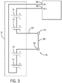
- the service disconnect unit 16 is included in the battery system 12, as illustrated in FIG. 3 .
- the service disconnect unit 16 includes a removable conductive member 50 which, when inserted, electrically couples a first portion 54 of a bus bar 52 and a second portion 56 of the bus bar 52 of the battery module.
- the battery system 12 includes a plurality of battery modules 14 having cells, which are electrically connected in series to generate a voltage across a positive high voltage terminal 58 and a negative high voltage terminal 60.
- the positive high voltage terminal 58 and the negative high voltage terminal 60 may electrically couple and provide power to the power systems of the xEV 10.
- the service disconnect unit 16 electrically couples the first portion 54 and the second portion 56 of the bus bar 52 to allow current to flow through the battery system 12.
- a technician may disengage the service disconnect unit 16 by disengaging the removable conductive member 50 to electrically isolate each half of the battery system 12, thus allowing the technician to work on the xEV 10.
- the removable conductive member 50 may be configured to be removed with a cover of the battery system 12 housing, such that when the cover of the battery system 12 housing is removed, the conductive member 50 is removed so that the service disconnect unit 16 automatically disables the battery system 12.
- one or more service disconnect units 16 may be included among the bus bars 52 connecting the battery modules 14.
- the removable conductive member(s) 50 of the one or more service disconnect units 16 may not be inserted until the end of the manufacturing process, such that the circuit between the battery modules 14 is incomplete for all or a portion of the manufacturing process. In this way, the voltage across the battery system 12 may be reduced during the manufacturing process to provide the benefit of not working with a high voltage circuit during manufacturing due to one or more of the service disconnect units 16 being open.
- no portion of the battery system 12 will be above a certain voltage level, such as 60V for example, during the manufacturing process
- the battery system 12 may include one or more battery modules 14, which may be connected to each other in series.
- Each battery module 14 may include a plurality of electrochemical cells, such as lithium-ion cells.
- bus bars 52 may electrically couple the positive terminal 58 of one battery module 14 with a negative terminal 60 of a second battery module 14. In this way, multiple battery modules 14 may be connected in series to provide a desired electrical power output to a vehicle propulsion system or other load.
- the bus bar 52 may be different from the other bus bars 52 that are not service disconnect units 16.
- the bus bar 52 of the service disconnect unit 16 includes a first portion 54 and a second portion 56 that are electrically insulated from one another by a casing 130, which is made of an electrically insulating material, such as plastic.
- the first and second portions 54 and 56 may be electrically coupled to each other by the removable conductive member 50 to link the positive high voltage terminal 58 and the negative high voltage terminal 60.
- the bus bar portions 54 and 56 may be formed from copper, or any other conductive material known to those skilled in the art.
- the removable conductive member 50 may be inserted into an opening 62 that extends through the first and second portions 54 and 56 of the bus bar 52 to electrically couple the two portions 54 and 56.
- the removable conductive member 50 is removed from the opening 62, the first and second portions 54 and 56 of the bus bar 52 are no longer electrically connected to each other, and the battery system 12 is disabled. It should be understood that the removable conductive member 50 does not necessarily need to be completely removed from the opening 62 to disconnect the terminals of the battery modules 14; the member 50 need only be moved far enough that current flow between the first portion 54 and the second portion 56 is interrupted.
- the removable conductive member 50 may be configured to reversibly interrupt the electrical connection between the first and second portions 54 and 56, such that when the user is finished servicing the battery system 12, the user may re-insert the removable conductive member 50 to restore electrical conductivity between the first and second portions 54 and 56.
- multiple service disconnect units 16 may be used.
- multiple service disconnect units 16 may be used to keep the voltage present at any one service disconnect unit 16 below a predetermined voltage limit, e.g., 60 volts.
- FIG. 5 shows the first portion 54 of the bus bar and the second portion 56 of the bus bar.
- the two portions 54 and 56 may be similar in size, shape, and design, and, when present in the battery system 12, they may electrically connect the negative terminal 60 of one battery module 14 to the positive terminal 58 of an adjacent battery module in the battery system.
- Each portion 54 and 56 of the bus bar 52 is configured to attach to a battery module 14 terminal (e.g., positive terminal 58 or negative terminal 60) at a first end 100, which may include an opening 98 for mounting.
- Each portion 54 and 56 may also include a connector 102 to receive a removable conductive member 50 at a second end 104.
- Each connector 102 may include an aperture 106, with the apertures 106 comprising the opening 62 configured to receive the removable conductive member 50.
- the connectors 102 of the first and second portions 54 and 56 of the bus bar 52 may be axially 80 aligned such that the removable conductive member 50 may extend through the two connectors 102 and electrically couple the first portion 54 of the bus bar 52 with the second portion 56 of the bus bar 52.
- Each connector 102 may include a compression or pressure fitting configured to receive the removable conductive member 50.
- a compressible metallic sleeve may be included inside the connector 102 to provide an electrical contact interface between the connector 102 and the removable conductive member 50 (e.g., the pin 150).
- the compressible metallic sleeve may be configured to receive the removable conductive member 50, and may further be configured to exert a force radially inward on the removable conductive member 50, thereby holding the removable conductive member 50 in place and securing an electrical connection between the removable conductive member 50 and the connector 102. It is understood that any suitable technique that provides an electrical connection between the removable conductive member 50 and the connector 102 may be employed.
- first and second portions 54 and 56 of the bus bar 52 may be oriented to overlap each other.
- a gap 108 may be formed between each portion 54 and 56 by a bend 110.
- the first and second portions 54 and 56 of the bus bar 52 may be electrically insulated from each other by a casing 130, as shown in FIG. 6 , which may be constructed of plastic or other suitable non-conductive material.
- the casing 130 may ensure that the first and second portions 54 and 56 of the bus bar 52 are insulated from each other, and ensure that the outer surface 132 of the service disconnect unit 16 is non-conductive.
- the casing 130 may be injection molded over the portions 54 and 56 of the bus bar 52, for example.
- the insulating casing 130 may include terminal openings 134 generally aligned with the openings 98 to enable each portion 54 and 56 of the bus bar 52 to electrically connect to the battery module 14.
- the casing 130 may also include a connector portion 136 that surrounds at least one of the connectors 62 to facilitate attachment of the conductive member 50.
- the connector portion 136 may extend axially beyond the connector 62 of one or both portions 54 and 56 of the bus bar 52 to provide structural support, to ensure electrical isolation from the outer surface 132, and/or to help set the depth of the removable conductive member 50 in the opening 62, among other things.
- FIG. 7 illustrates an embodiment of the removable conductive member 50 that may electrically couple the first and second portions 54 and 56 of the bus bar 52 together.
- the removable conductive member 50 may include a pin 152 constructed of an electrically conductive material, such as copper.
- the pin 152 may be configured to extend into the connectors 102 of the portions 54 and 56 of the bus bar 52 to make the appropriate electrical connection between the two portions 54 and 56 of the bus bar 52.
- the connectors 102 may include an attachment device, such as a compression or pressure fitting, threaded connection, or quick disconnect system, to provide electrical contact between the connector 102 and the pin 152.
- the conductive member 50 may also include a head 154 that extends around a portion of the pin 152.
- the head 154 may be constructed of a non-conductive material, such as plastic, and may fit over the connector portion 136 of the casing 130 to ensure that no conductive portions of the service disconnect unit 16 are exposed to the outer surface 132.
- the head 154 may include a lip 156 that extends radially 82 outward.
- the head 154 may also include a protrusion 158 that extends from the top surface 160 of the head 154, which may act as a handle to allow the user to more easily insert and remove the conductive member 50.
- the protrusion 158 is shown as a rectangular protrusion, but it is understood that the protrusion 158 could take other shapes or forms, including a tab, a loop, or a hook.
- the head 154 and the connector portion 136 may be threaded or otherwise configured to secure the conductive member 50 to the casing 130.
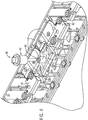
- a cover 200 of a housing 202 for the battery system 12 may fit over the top of the battery module 14, as shown in FIG. 8 .
- the cover 200 may include a plug 204 disposed over the removable conductive member 50.
- the plug 204 may be mechanically coupled to the cover 200.
- the plug 204 may include a plastic nut 206 that couples to the top surface 160 of the removable conductive member 50, such as by threading so that the removal of the cover 200 also removes the conductive member 50.
- the plug 204 on the cover 200 of the battery system 12 may axially overlap the removable conductive member 50, and the plug 204 may be configured to be removed to allow the user to remove the removable conductive member 50, such that the removable conductive member 50 may be pulled through the cover 200 of the battery system 12 housing 202 while the cover 200 remains in place.
- the cover 200 of the battery system 12 include a plug 204 for each removable conductive member 50.
- the cover of the battery system 12 may enable the user to disengage a plurality of service disconnect units 16, either via removal with the cover 200, or removal through the cover 200 (e.g., such as through plugs 204).
Applications Claiming Priority (3)
| Application Number | Priority Date | Filing Date | Title |
|---|---|---|---|
| US201261656378P | 2012-06-06 | 2012-06-06 | |
| US13/910,895 US9368782B2 (en) | 2012-06-06 | 2013-06-05 | Manufacturing service disconnect that is part of busbar |
| PCT/US2013/044533 WO2013184926A1 (en) | 2012-06-06 | 2013-06-06 | Manufacturing service disconnect that is part of busbar |
Publications (2)
| Publication Number | Publication Date |
|---|---|
| EP2858848A1 EP2858848A1 (en) | 2015-04-15 |
| EP2858848B1 true EP2858848B1 (en) | 2019-10-09 |
Family
ID=48652359
Family Applications (1)
| Application Number | Title | Priority Date | Filing Date |
|---|---|---|---|
| EP13729891.5A Active EP2858848B1 (en) | 2012-06-06 | 2013-06-06 | Manufacturing service disconnect that is part of busbar |
Country Status (4)
| Country | Link |
|---|---|
| US (1) | US9368782B2 (zh) |
| EP (1) | EP2858848B1 (zh) |
| CN (1) | CN104602946B (zh) |
| WO (1) | WO2013184926A1 (zh) |
Families Citing this family (13)
| Publication number | Priority date | Publication date | Assignee | Title |
|---|---|---|---|---|
| US9532476B2 (en) * | 2014-02-18 | 2016-12-27 | Labinal, Llc | Switching assembly and interconnect assembly therefor |
| DE102014006030A1 (de) | 2014-04-24 | 2015-10-29 | Audi Ag | Kraftfahrzeug-Batteriemontage mit Hochvoltschutz |
| CN113381129B (zh) * | 2015-01-05 | 2024-03-29 | Cps科技控股有限公司 | 具有引导延伸部系统的蓄电池模块汇流条载体及方法 |
| KR102395481B1 (ko) * | 2015-03-11 | 2022-05-06 | 삼성에스디아이 주식회사 | 이차 전지 |
| JP6865053B2 (ja) * | 2016-02-19 | 2021-04-28 | 株式会社Gsユアサ | 蓄電装置 |
| US10516144B2 (en) * | 2016-02-19 | 2019-12-24 | Gs Yuasa International Ltd. | Energy storage apparatus |
| DE102016103839B4 (de) * | 2016-03-03 | 2018-09-20 | Johnson Controls Advanced Power Solutions Gmbh | Signalverbinder für ein Batteriemodul |
| FR3051605B1 (fr) * | 2016-05-20 | 2021-07-23 | Renault Sas | Batterie electrique haute tension securisee |
| KR102399621B1 (ko) * | 2017-05-12 | 2022-05-18 | 현대자동차주식회사 | 배터리 시스템 |
| US10756552B2 (en) | 2017-10-31 | 2020-08-25 | General Electric Company | Manual service disconnect system and method for energy storage |
| CN112913074A (zh) * | 2018-11-13 | 2021-06-04 | 瑞伟安知识产权控股有限公司 | 用于电池系统的手动维护断开装置 |
| KR20210059433A (ko) * | 2019-11-15 | 2021-05-25 | 주식회사 엘지화학 | 외부 브릿지 버스바를 포함하는 고전압 전지모듈 |
| DE102020133040A1 (de) | 2020-12-10 | 2022-06-15 | Bayerische Motoren Werke Aktiengesellschaft | Batteriemodul mit Schaltvorrichtung und Energiemodul mit mehreren Batteriemodulen |
Citations (1)
| Publication number | Priority date | Publication date | Assignee | Title |
|---|---|---|---|---|
| US20120003507A1 (en) * | 2009-03-12 | 2012-01-05 | Berengar Krieg | Battery system having an output voltage of more than 60 v direct current voltage |
Family Cites Families (5)
| Publication number | Priority date | Publication date | Assignee | Title |
|---|---|---|---|---|
| US4106833A (en) | 1977-09-02 | 1978-08-15 | The United States Of America As Represented By The Secretary Of The Navy | Quick disconnect intercell busbar for deep submergence batteries |
| US6842339B2 (en) * | 2002-03-01 | 2005-01-11 | High Tech Computer, Corp | Affixing device for affixing front cover, back cover and battery unit of a personal digital assistant |
| KR100868255B1 (ko) * | 2005-04-19 | 2008-11-11 | 주식회사 엘지화학 | 단자 연결장치 |
| US7229327B2 (en) * | 2005-05-25 | 2007-06-12 | Alcoa Fujikura Limited | Canted coil spring power terminal and sequence connection system |
| KR100684763B1 (ko) * | 2005-07-29 | 2007-02-20 | 삼성에스디아이 주식회사 | 이차 전지 모듈과 이차 전지 모듈의 단위 전지 연결구 |
-
2013
- 2013-06-05 US US13/910,895 patent/US9368782B2/en active Active
- 2013-06-06 CN CN201380030004.8A patent/CN104602946B/zh active Active
- 2013-06-06 EP EP13729891.5A patent/EP2858848B1/en active Active
- 2013-06-06 WO PCT/US2013/044533 patent/WO2013184926A1/en active Application Filing
Patent Citations (1)
| Publication number | Priority date | Publication date | Assignee | Title |
|---|---|---|---|---|
| US20120003507A1 (en) * | 2009-03-12 | 2012-01-05 | Berengar Krieg | Battery system having an output voltage of more than 60 v direct current voltage |
Also Published As
| Publication number | Publication date |
|---|---|
| US9368782B2 (en) | 2016-06-14 |
| WO2013184926A1 (en) | 2013-12-12 |
| CN104602946B (zh) | 2017-05-31 |
| CN104602946A (zh) | 2015-05-06 |
| EP2858848A1 (en) | 2015-04-15 |
| US20130330594A1 (en) | 2013-12-12 |
Similar Documents
| Publication | Publication Date | Title |
|---|---|---|
| EP2858848B1 (en) | Manufacturing service disconnect that is part of busbar | |
| US11909061B2 (en) | Modular approach for advanced battery modules having different electrical characteristics | |
| US9209628B2 (en) | Systems and methods for de-energizing battery packs | |
| US8466586B2 (en) | High-voltage terminal assembly with integral high-voltage interlock | |
| US9533639B2 (en) | High voltage connector system and method | |
| US9520587B2 (en) | Bus bar assembly carrier | |
| EP3183763B1 (en) | Lead frame for a battery module having sacrificial interconnects | |
| CN108112244B (zh) | 用于电池组模块的连接器筒 | |
| US20160197383A1 (en) | Circuitry harness and pass through for lead wires of a battery module | |
| US9577230B2 (en) | Integrated high voltage service disconnect for traction batteries | |
| CN108604803B (zh) | 集成电池安全互锁器 | |
| WO2013126443A1 (en) | Prismatic electrochemical cell | |
| EP3201975B1 (en) | Battery module bus bar connection assembly | |
| WO2017201033A1 (en) | Push fit main battery terminal connectors with geometrical lockout features | |
| US11664624B2 (en) | Electrical connectors with disconnection blocking features | |
| US9553288B2 (en) | Step configuration for traction battery housing | |
| US20220271394A1 (en) | Battery module and bus bar having stress-relieving features |
Legal Events
| Date | Code | Title | Description |
|---|---|---|---|
| PUAI | Public reference made under article 153(3) epc to a published international application that has entered the european phase |
Free format text: ORIGINAL CODE: 0009012 |
|
| 17P | Request for examination filed |
Effective date: 20141203 |
|
| AK | Designated contracting states |
Kind code of ref document: A1 Designated state(s): AL AT BE BG CH CY CZ DE DK EE ES FI FR GB GR HR HU IE IS IT LI LT LU LV MC MK MT NL NO PL PT RO RS SE SI SK SM TR |
|
| AX | Request for extension of the european patent |
Extension state: BA ME |
|
| DAX | Request for extension of the european patent (deleted) | ||
| STAA | Information on the status of an ep patent application or granted ep patent |
Free format text: STATUS: EXAMINATION IS IN PROGRESS |
|
| 17Q | First examination report despatched |
Effective date: 20171122 |
|
| REG | Reference to a national code |
Ref country code: DE Ref legal event code: R079 Ref document number: 602013061447 Country of ref document: DE Free format text: PREVIOUS MAIN CLASS: B60L0003000000 Ipc: F16P0003000000 |
|
| GRAP | Despatch of communication of intention to grant a patent |
Free format text: ORIGINAL CODE: EPIDOSNIGR1 |
|
| STAA | Information on the status of an ep patent application or granted ep patent |
Free format text: STATUS: GRANT OF PATENT IS INTENDED |
|
| RIC1 | Information provided on ipc code assigned before grant |
Ipc: F16P 3/00 20060101AFI20190315BHEP Ipc: B60L 50/16 20190101ALI20190315BHEP Ipc: B60L 50/64 20190101ALI20190315BHEP Ipc: H01M 2/20 20060101ALI20190315BHEP Ipc: H01R 13/633 20060101ALI20190315BHEP Ipc: H01R 11/28 20060101ALI20190315BHEP Ipc: B60L 50/60 20190101ALI20190315BHEP Ipc: B60L 58/26 20190101ALI20190315BHEP Ipc: B60L 58/21 20190101ALI20190315BHEP Ipc: H01M 2/34 20060101ALI20190315BHEP |
|
| INTG | Intention to grant announced |
Effective date: 20190417 |
|
| RAP1 | Party data changed (applicant data changed or rights of an application transferred) |
Owner name: CPS TECHNOLOGY HOLDINGS LLC |
|
| GRAS | Grant fee paid |
Free format text: ORIGINAL CODE: EPIDOSNIGR3 |
|
| GRAA | (expected) grant |
Free format text: ORIGINAL CODE: 0009210 |
|
| STAA | Information on the status of an ep patent application or granted ep patent |
Free format text: STATUS: THE PATENT HAS BEEN GRANTED |
|
| AK | Designated contracting states |
Kind code of ref document: B1 Designated state(s): AL AT BE BG CH CY CZ DE DK EE ES FI FR GB GR HR HU IE IS IT LI LT LU LV MC MK MT NL NO PL PT RO RS SE SI SK SM TR |
|
| REG | Reference to a national code |
Ref country code: GB Ref legal event code: FG4D |
|
| REG | Reference to a national code |
Ref country code: CH Ref legal event code: EP |
|
| REG | Reference to a national code |
Ref country code: IE Ref legal event code: FG4D |
|
| REG | Reference to a national code |
Ref country code: DE Ref legal event code: R096 Ref document number: 602013061447 Country of ref document: DE |
|
| REG | Reference to a national code |
Ref country code: AT Ref legal event code: REF Ref document number: 1189244 Country of ref document: AT Kind code of ref document: T Effective date: 20191115 |
|
| REG | Reference to a national code |
Ref country code: NL Ref legal event code: MP Effective date: 20191009 |
|
| REG | Reference to a national code |
Ref country code: LT Ref legal event code: MG4D |
|
| REG | Reference to a national code |
Ref country code: AT Ref legal event code: MK05 Ref document number: 1189244 Country of ref document: AT Kind code of ref document: T Effective date: 20191009 |
|
| PG25 | Lapsed in a contracting state [announced via postgrant information from national office to epo] |
Ref country code: FI Free format text: LAPSE BECAUSE OF FAILURE TO SUBMIT A TRANSLATION OF THE DESCRIPTION OR TO PAY THE FEE WITHIN THE PRESCRIBED TIME-LIMIT Effective date: 20191009 Ref country code: LT Free format text: LAPSE BECAUSE OF FAILURE TO SUBMIT A TRANSLATION OF THE DESCRIPTION OR TO PAY THE FEE WITHIN THE PRESCRIBED TIME-LIMIT Effective date: 20191009 Ref country code: BG Free format text: LAPSE BECAUSE OF FAILURE TO SUBMIT A TRANSLATION OF THE DESCRIPTION OR TO PAY THE FEE WITHIN THE PRESCRIBED TIME-LIMIT Effective date: 20200109 Ref country code: GR Free format text: LAPSE BECAUSE OF FAILURE TO SUBMIT A TRANSLATION OF THE DESCRIPTION OR TO PAY THE FEE WITHIN THE PRESCRIBED TIME-LIMIT Effective date: 20200110 Ref country code: AT Free format text: LAPSE BECAUSE OF FAILURE TO SUBMIT A TRANSLATION OF THE DESCRIPTION OR TO PAY THE FEE WITHIN THE PRESCRIBED TIME-LIMIT Effective date: 20191009 Ref country code: PT Free format text: LAPSE BECAUSE OF FAILURE TO SUBMIT A TRANSLATION OF THE DESCRIPTION OR TO PAY THE FEE WITHIN THE PRESCRIBED TIME-LIMIT Effective date: 20200210 Ref country code: ES Free format text: LAPSE BECAUSE OF FAILURE TO SUBMIT A TRANSLATION OF THE DESCRIPTION OR TO PAY THE FEE WITHIN THE PRESCRIBED TIME-LIMIT Effective date: 20191009 Ref country code: LV Free format text: LAPSE BECAUSE OF FAILURE TO SUBMIT A TRANSLATION OF THE DESCRIPTION OR TO PAY THE FEE WITHIN THE PRESCRIBED TIME-LIMIT Effective date: 20191009 Ref country code: SE Free format text: LAPSE BECAUSE OF FAILURE TO SUBMIT A TRANSLATION OF THE DESCRIPTION OR TO PAY THE FEE WITHIN THE PRESCRIBED TIME-LIMIT Effective date: 20191009 Ref country code: NL Free format text: LAPSE BECAUSE OF FAILURE TO SUBMIT A TRANSLATION OF THE DESCRIPTION OR TO PAY THE FEE WITHIN THE PRESCRIBED TIME-LIMIT Effective date: 20191009 Ref country code: PL Free format text: LAPSE BECAUSE OF FAILURE TO SUBMIT A TRANSLATION OF THE DESCRIPTION OR TO PAY THE FEE WITHIN THE PRESCRIBED TIME-LIMIT Effective date: 20191009 Ref country code: NO Free format text: LAPSE BECAUSE OF FAILURE TO SUBMIT A TRANSLATION OF THE DESCRIPTION OR TO PAY THE FEE WITHIN THE PRESCRIBED TIME-LIMIT Effective date: 20200109 |
|
| PG25 | Lapsed in a contracting state [announced via postgrant information from national office to epo] |
Ref country code: IS Free format text: LAPSE BECAUSE OF FAILURE TO SUBMIT A TRANSLATION OF THE DESCRIPTION OR TO PAY THE FEE WITHIN THE PRESCRIBED TIME-LIMIT Effective date: 20200224 Ref country code: HR Free format text: LAPSE BECAUSE OF FAILURE TO SUBMIT A TRANSLATION OF THE DESCRIPTION OR TO PAY THE FEE WITHIN THE PRESCRIBED TIME-LIMIT Effective date: 20191009 Ref country code: RS Free format text: LAPSE BECAUSE OF FAILURE TO SUBMIT A TRANSLATION OF THE DESCRIPTION OR TO PAY THE FEE WITHIN THE PRESCRIBED TIME-LIMIT Effective date: 20191009 |
|
| PG25 | Lapsed in a contracting state [announced via postgrant information from national office to epo] |
Ref country code: AL Free format text: LAPSE BECAUSE OF FAILURE TO SUBMIT A TRANSLATION OF THE DESCRIPTION OR TO PAY THE FEE WITHIN THE PRESCRIBED TIME-LIMIT Effective date: 20191009 |
|
| REG | Reference to a national code |
Ref country code: DE Ref legal event code: R097 Ref document number: 602013061447 Country of ref document: DE |
|
| PG2D | Information on lapse in contracting state deleted |
Ref country code: IS |
|
| PG25 | Lapsed in a contracting state [announced via postgrant information from national office to epo] |
Ref country code: CZ Free format text: LAPSE BECAUSE OF FAILURE TO SUBMIT A TRANSLATION OF THE DESCRIPTION OR TO PAY THE FEE WITHIN THE PRESCRIBED TIME-LIMIT Effective date: 20191009 Ref country code: RO Free format text: LAPSE BECAUSE OF FAILURE TO SUBMIT A TRANSLATION OF THE DESCRIPTION OR TO PAY THE FEE WITHIN THE PRESCRIBED TIME-LIMIT Effective date: 20191009 Ref country code: EE Free format text: LAPSE BECAUSE OF FAILURE TO SUBMIT A TRANSLATION OF THE DESCRIPTION OR TO PAY THE FEE WITHIN THE PRESCRIBED TIME-LIMIT Effective date: 20191009 Ref country code: DK Free format text: LAPSE BECAUSE OF FAILURE TO SUBMIT A TRANSLATION OF THE DESCRIPTION OR TO PAY THE FEE WITHIN THE PRESCRIBED TIME-LIMIT Effective date: 20191009 Ref country code: IS Free format text: LAPSE BECAUSE OF FAILURE TO SUBMIT A TRANSLATION OF THE DESCRIPTION OR TO PAY THE FEE WITHIN THE PRESCRIBED TIME-LIMIT Effective date: 20200209 |
|
| PLBE | No opposition filed within time limit |
Free format text: ORIGINAL CODE: 0009261 |
|
| STAA | Information on the status of an ep patent application or granted ep patent |
Free format text: STATUS: NO OPPOSITION FILED WITHIN TIME LIMIT |
|
| PG25 | Lapsed in a contracting state [announced via postgrant information from national office to epo] |
Ref country code: SK Free format text: LAPSE BECAUSE OF FAILURE TO SUBMIT A TRANSLATION OF THE DESCRIPTION OR TO PAY THE FEE WITHIN THE PRESCRIBED TIME-LIMIT Effective date: 20191009 Ref country code: SM Free format text: LAPSE BECAUSE OF FAILURE TO SUBMIT A TRANSLATION OF THE DESCRIPTION OR TO PAY THE FEE WITHIN THE PRESCRIBED TIME-LIMIT Effective date: 20191009 Ref country code: IT Free format text: LAPSE BECAUSE OF FAILURE TO SUBMIT A TRANSLATION OF THE DESCRIPTION OR TO PAY THE FEE WITHIN THE PRESCRIBED TIME-LIMIT Effective date: 20191009 |
|
| 26N | No opposition filed |
Effective date: 20200710 |
|
| PG25 | Lapsed in a contracting state [announced via postgrant information from national office to epo] |
Ref country code: SI Free format text: LAPSE BECAUSE OF FAILURE TO SUBMIT A TRANSLATION OF THE DESCRIPTION OR TO PAY THE FEE WITHIN THE PRESCRIBED TIME-LIMIT Effective date: 20191009 |
|
| PG25 | Lapsed in a contracting state [announced via postgrant information from national office to epo] |
Ref country code: MC Free format text: LAPSE BECAUSE OF FAILURE TO SUBMIT A TRANSLATION OF THE DESCRIPTION OR TO PAY THE FEE WITHIN THE PRESCRIBED TIME-LIMIT Effective date: 20191009 |
|
| REG | Reference to a national code |
Ref country code: CH Ref legal event code: PL |
|
| PG25 | Lapsed in a contracting state [announced via postgrant information from national office to epo] |
Ref country code: LU Free format text: LAPSE BECAUSE OF NON-PAYMENT OF DUE FEES Effective date: 20200606 |
|
| REG | Reference to a national code |
Ref country code: BE Ref legal event code: MM Effective date: 20200630 |
|
| PG25 | Lapsed in a contracting state [announced via postgrant information from national office to epo] |
Ref country code: CH Free format text: LAPSE BECAUSE OF NON-PAYMENT OF DUE FEES Effective date: 20200630 Ref country code: LI Free format text: LAPSE BECAUSE OF NON-PAYMENT OF DUE FEES Effective date: 20200630 Ref country code: IE Free format text: LAPSE BECAUSE OF NON-PAYMENT OF DUE FEES Effective date: 20200606 |
|
| PG25 | Lapsed in a contracting state [announced via postgrant information from national office to epo] |
Ref country code: BE Free format text: LAPSE BECAUSE OF NON-PAYMENT OF DUE FEES Effective date: 20200630 |
|
| PG25 | Lapsed in a contracting state [announced via postgrant information from national office to epo] |
Ref country code: TR Free format text: LAPSE BECAUSE OF FAILURE TO SUBMIT A TRANSLATION OF THE DESCRIPTION OR TO PAY THE FEE WITHIN THE PRESCRIBED TIME-LIMIT Effective date: 20191009 Ref country code: MT Free format text: LAPSE BECAUSE OF FAILURE TO SUBMIT A TRANSLATION OF THE DESCRIPTION OR TO PAY THE FEE WITHIN THE PRESCRIBED TIME-LIMIT Effective date: 20191009 Ref country code: CY Free format text: LAPSE BECAUSE OF FAILURE TO SUBMIT A TRANSLATION OF THE DESCRIPTION OR TO PAY THE FEE WITHIN THE PRESCRIBED TIME-LIMIT Effective date: 20191009 |
|
| PG25 | Lapsed in a contracting state [announced via postgrant information from national office to epo] |
Ref country code: MK Free format text: LAPSE BECAUSE OF FAILURE TO SUBMIT A TRANSLATION OF THE DESCRIPTION OR TO PAY THE FEE WITHIN THE PRESCRIBED TIME-LIMIT Effective date: 20191009 |
|
| PGFP | Annual fee paid to national office [announced via postgrant information from national office to epo] |
Ref country code: FR Payment date: 20230626 Year of fee payment: 11 Ref country code: DE Payment date: 20230626 Year of fee payment: 11 |
|
| PGFP | Annual fee paid to national office [announced via postgrant information from national office to epo] |
Ref country code: GB Payment date: 20230627 Year of fee payment: 11 |