EP2858542B1 - Stick mixer driven food processor - Google Patents
Stick mixer driven food processor Download PDFInfo
- Publication number
- EP2858542B1 EP2858542B1 EP13800077.3A EP13800077A EP2858542B1 EP 2858542 B1 EP2858542 B1 EP 2858542B1 EP 13800077 A EP13800077 A EP 13800077A EP 2858542 B1 EP2858542 B1 EP 2858542B1
- Authority
- EP
- European Patent Office
- Prior art keywords
- coupling
- recess
- gear box
- lid
- spindle
- Prior art date
- Legal status (The legal status is an assumption and is not a legal conclusion. Google has not performed a legal analysis and makes no representation as to the accuracy of the status listed.)
- Active
Links
Images


Classifications
-
- A—HUMAN NECESSITIES
- A47—FURNITURE; DOMESTIC ARTICLES OR APPLIANCES; COFFEE MILLS; SPICE MILLS; SUCTION CLEANERS IN GENERAL
- A47J—KITCHEN EQUIPMENT; COFFEE MILLS; SPICE MILLS; APPARATUS FOR MAKING BEVERAGES
- A47J43/00—Implements for preparing or holding food, not provided for in other groups of this subclass
- A47J43/04—Machines for domestic use not covered elsewhere, e.g. for grinding, mixing, stirring, kneading, emulsifying, whipping or beating foodstuffs, e.g. power-driven
- A47J43/044—Machines for domestic use not covered elsewhere, e.g. for grinding, mixing, stirring, kneading, emulsifying, whipping or beating foodstuffs, e.g. power-driven with tools driven from the top side
-
- A—HUMAN NECESSITIES
- A47—FURNITURE; DOMESTIC ARTICLES OR APPLIANCES; COFFEE MILLS; SPICE MILLS; SUCTION CLEANERS IN GENERAL
- A47J—KITCHEN EQUIPMENT; COFFEE MILLS; SPICE MILLS; APPARATUS FOR MAKING BEVERAGES
- A47J44/00—Multi-purpose machines for preparing food with several driving units
- A47J44/02—Multi-purpose machines for preparing food with several driving units with provisions for drive either from top or from bottom, e.g. for separately-driven bowl
-
- A—HUMAN NECESSITIES
- A47—FURNITURE; DOMESTIC ARTICLES OR APPLIANCES; COFFEE MILLS; SPICE MILLS; SUCTION CLEANERS IN GENERAL
- A47J—KITCHEN EQUIPMENT; COFFEE MILLS; SPICE MILLS; APPARATUS FOR MAKING BEVERAGES
- A47J43/00—Implements for preparing or holding food, not provided for in other groups of this subclass
- A47J43/04—Machines for domestic use not covered elsewhere, e.g. for grinding, mixing, stirring, kneading, emulsifying, whipping or beating foodstuffs, e.g. power-driven
- A47J43/044—Machines for domestic use not covered elsewhere, e.g. for grinding, mixing, stirring, kneading, emulsifying, whipping or beating foodstuffs, e.g. power-driven with tools driven from the top side
- A47J2043/04454—Apparatus of counter top type
Definitions
- the present invention provides a food processing lid as set forth in claim 1.
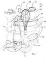
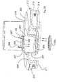
- a kitchen appliance 10 comprises a platform or base 11 having feet 12 that are adapted to rest on a kitchen countertop.
- the base 11 has moulded in features 12 adapted to retain the handle portion 14 of a stick mixer and the stick mixer's accessories.
- the base 11 can support the stick mixer's removable stem and blade assembly 15 and/or the stick mixer's whisk accessory 16.
- the stick mixer component retaining features 13 are shaped to cooperate with and couple with the various components of the stick mixer 14, 15, 16.
- the lid of the food processor 20 further comprises an integral feed tube 21 and the food processor's pusher 22.
- the lid also features a recess 23 that is adapted to removably receive a gear box assembly 24.
- the recess is shown as a concavity with respect to the upper surface 20a. It will be appreciated that the recess 23 may be located above the upper surface 20a or partially above and partially below the upper surface 20a of the lid 20.
- a compression spring 56 within the spindle 51 acts to disengage the spindle 51 from the post 50.
- the lid 20 has male bayonet components 57 and the interior rim of the bowl 18 has female bayonet components 58.
- the bayonet components 57, 58 ensure that the descending rim 59 of the lid 18 is fully inserted and temporarily locked with respect to the bowl 18 once the lid is inserted and rotated into position particularly with respect to food processor lids that incorporate an integral gear box, the lid depicted (for example) in Figure 9 , because of the descending rim 59 allows the bowl to have a greater effective volume for a given bowl size. This is because the volume between the lowest edge of the descending rim 59 and the under surface of the top of the lid forms a void 59a rather than being occupied with the operational components of a gear box that is fully contained within the lid structure.
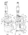
- the female component 63 of the intermediate coupling 61 comprises three splines adapted to couple with the cooperating tip 64 of the food processor's main spindle 51.
- the female component and the through opening that receives it, are in the middle or center of the lid, even though the gearbox need not be central to the lid. Because the number of splines on the tip of the spindle 64 is different than the number of splines in the female component 60, 83 of the gear box female coupling component, there can be no direct engagement between the gear box 80 and the spindle 51. Direct interconnection between the gear box coupling 83 and the tip of the spindle 64 can be prevented in other ways.
- Figure 19 illustrates the disconnection between the gears 183 and the splines or recesses that are in a fixed orientation relative to the main body of the spindle.
- the reciprocating locator 189 comprises an upper pocket 193 for receiving the lower end of the compression spring 191.
- the lower extent 194 of the locator 189 further comprises a circumferential groove 195 for receiving a polymeric seal 196.
- the seal 196 inhibits migration of undesirable foods or liquids into the area above the seal 196.
- a second seal 197 is located within the flange 185 and extends between the flange and spline component 185, 186 and the outer diameter of the effective main body portion of the spindle. This seal 197 prevents food from migrating into the internal cavity of the spindle.
- Figure 19a also illustrates the vertical splines 199 located below the vertically slotted coupling or tip 200 of the spindle. The vertical splines 199 are for engaging the various blades and accessories associated with a spindle.
- Figure 20 also illustrates the space, recess or pocket 209 formed between the upper surface of the lid 210 and the lower rim of the lid 211.
- This pocket 209 effectively increases the capacity of the food processing bowl relative to those kinds of lids that incorporate an integral gear box.
- the lid also features an upper flange 212 below which is located a descending rim 213 having a circumferential groove 214 for polymeric seal.
- male bayonet features 215 are located on the descending rim 213.
Description
- The invention relates to food processors and more particularly to a food processor that is driven by the motor in a hand held or stick mixer.
- Food processors are well known. It is also known to drive a food processor with the motor in a hand held or stick mixer. A stick mixer generally comprises a handle that houses a motor and that is mechanically coupled to a stem that features a blade at one end and coupling for the motor at the other end. Because the handle and the stem of the stick mixer can be separated the handle portion can be used to drive the rotating blade of a food processor. However, the motor output speed of the stick mixer is high (about 15,000 rpm) and a standard food processor blade requires only about 1500 rpm, a speed reducing gear box is required between the stick mixer's motor and the mechanical input of the food processor. Prior art units, such as those disclosed in
EP 1304 064 andCN 201082133 , have a gear box that is permanently housed within the lid of the food processor. However, because of the presence of the gear box, the lid is generally not recommended for or capable of submersion or dish washer cleaning.DE 1 251 479 discloses various arrangements of reduction gearing that can be used to rotate a food processor tool at a lower speed than that provided by a drive motor. - It is an object of the invention to provide an appliance that combines a stick mixer and a food processor and in which a gear box that is interposed between the motor of the stick mixer and the mechanical input of the food processor is removable from a lid of the food processor.
- The present invention provides a food processing lid as set forth in claim 1.
- According to the invention, the removable gear box allows the lid to be washed in a dish washer.
- In certain embodiments of the technology, the removable gear box is shielded from food by the lid.
- In other embodiments, the lid that retains the gear box can be moulded in a clear material that allows visibility of the food within the food processor.
- In some embodiments, the intermediate coupling cannot be driven directly by the output spindle or shaft of the stick mixer. This safety feature requires the lid of the food processor to be attached to the bowl of the food processor before the spindle that holds the rotating blades of the food processor can be rotated.
- In preferred embodiments, storage base is provided. The storage base allows for an orderly holding of the necessary accessories and allows one or more food processor blades to be stored between the base and the food processor's bowl.
- In order that the invention be better understood, reference is now made to the following drawing figures in which:
-
FIGURE 1 is a perspective view of a stick mixer driven food processor, base and accessories. -
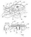
FIGURE 2 is a perspective view of the base, illustrating blade storage. -
FIGURE 3 is a cross section of the base and blade depicted inFIG. 2 . -
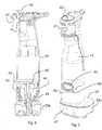
FIGURE 4 is a cross sectional view of a stick mixer, and gearbox. -
FIGURE 5 is perspective view of the handle and gearbox depicted inFigure 4 . -
FIGURE 6 is a perspective view of a food processor, bow, spindle, lid, gearbox and stick mixer handle. -
FIGURE 7 is a cross sectional view of the device depicted inFigure 6 . -
FIGURE 8 is a top perspective view of a lid with gearbox recess, intermediate coupling and separate gearbox. -
FIGURE 9 is an underside perspective of the lid, spindle and spindle coupling components. -
FIGURE 10 is a perspective view of a gearbox and lid. -
FIGURE 11 is an alternate embodiment of the components depicted inFigure 10 . -
FIGURE 12 is an alternate embodiment of the components depicted inFigure10 . -
FIGURE 13 is an alternate embodiment of the components depicted inFigure 10 . -
FIGURE 14 is an alternate embodiment of the components depicted inFigure 10 . -
FIGURE 15 is an alternate embodiment of the components depicted inFigure 10 . -
FIGURE 16 is an alternate embodiment of the components depicted inFigure 10 . -
FIGURE 17 is an alternate embodiment of the components depicted inFigure 10 . -
FIGURE 18 is a cross sectional view through the base of a spindle and stub shaft. -
FIGURE 19 is a cross section through line A-A ofFigure 18 . -
FIGURE 19a is a cross section of a spindle. -
FIGURE 20 is perspective view of a lid, partially broken away. -
FIGURE 21 is a schematic cross section of a lid, recess and removable gear box. -
FIGURE 22 is a schematic cross section of another embodiment of lid, recess and gear box. -
FIGURE 23 is a schematic cross section of a gear box, coupling and spindle. -
FIGURE 24 is a schematic cross section of another embodiment of a gear box, coupling and spindle. -
FIGURE 25 is a schematic cross section of yet another embodiment of gear box, coupling and spindle. -
FIGURE 26 is a schematic cross section of a gear box and recess, the gearbox having a safety finger shown as extended. -
FIGURE 27 is a schematic cross section of a gear box and recess, the gearbox having a safety finger shown as retracted. - As shown in
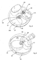
Figure 1 , akitchen appliance 10 comprises a platform orbase 11 havingfeet 12 that are adapted to rest on a kitchen countertop. Thebase 11 has moulded infeatures 12 adapted to retain thehandle portion 14 of a stick mixer and the stick mixer's accessories. For example, and as shown inFigure 1 , thebase 11 can support the stick mixer's removable stem andblade assembly 15 and/or the stick mixer'swhisk accessory 16. As illustrated, the stick mixercomponent retaining features 13 are shaped to cooperate with and couple with the various components of thestick mixer - The
base 11 is also adapted to removable retain thebowl assembly 17 of a food processor. In this example, thebowl assembly 17 comprises aprocessing bowl 18, itsintegral handle 19, and the lid of thefood processor 20. - In this example, the lid of the
food processor 20 further comprises anintegral feed tube 21 and the food processor'spusher 22. In this example, the lid also features arecess 23 that is adapted to removably receive agear box assembly 24. In this example, the recess is shown as a concavity with respect to theupper surface 20a. It will be appreciated that therecess 23 may be located above theupper surface 20a or partially above and partially below theupper surface 20a of thelid 20. - The
base 11 is further illustrated inFigures 2 and 3 . As shown in those figures, thebase 11 further comprises a circularupstanding rim 25 that cooperates with the base of thebowl 18. When the bowl is placed within therim 25 there is enough space between the bottom floor of thefood processor 26 and the upper surface of thebase 27 to accommodate one or more food processor accessories such as rotating blades orwhisking discs 28. - As shown in
Figure 2 , the receptacles for the stick mixer accessories each comprise acircumferential collar 29 that is configured to cooperate with the shape of the appropriate stick mixer component. In preferred embodiments, a pair of receptacles foraccessories front edge 37 ofbase 11 and located on the corners of the base 11 to either side of athird receptacle 38 that is configured and adapted to couple with thehandle portion 14 of a stick mixer. To allow better mechanical engagement with the handle, the middle receptacle in this example is provided with a pair ofrecesses 39 located on an interior side wall of thereceptacle 38 and opposite one another. Theserecesses 39 engage with the retractable clips located on thehandle portion 14. In particularly preferred embodiments, therecesses 39 engage with the retractable clips but not tightly, thereby allowing the handle to be inserted and withdrawn from thereceptacle 38 without manually disengaging or retracting the clips. These holders may also incorporate acylindrical core 30 having mechanical features such asrims 31 to better stabilise the appropriate stick mixer component with respect to thebase 11. - As best shown in
Figure 3 , theupper surface 27 of thebase 11, features a central opening and descendingcollar 32 adapted to receive thefemale coupling component 33 of a food processor accessory (as shown inFigure 3 ). - As suggested by
Figures 1 ,4 and 5 thehandle portion 14 of a stick mixer, in accordance with this example, comprises a hollow shell within which is located an electric motor having an output spindle or coupling component (either male or female, but in this example female coupling component). A half of a paired coupling arrangement is henceforth referred to as a "coupling component" 40. When two coupling components can cooperate to transmit torque they are deemed to have the same coupling configuration. If two coupling components can not cooperate, they are deemed to have a different coupling configuration. Thehandle component 14 also comprises auser activable switch 41 and optional user controls such as aspeed adjustment dial 42. Thecoupling component 40 extends from the bottom surface of the handle component and is adapted to engage cooperating couplings found within the collars of thevarious accessories handle portion 14.Ears handle portion 14 accommodate (as is known in the art)mechanical buttons 45, that when depressed simultaneously (disengage thehandle portion 14 from an accessory that is attached to it). - With reference to
Figures 4 and 5 , the accessory is amechanical gear box 24. Thegear box 24 couples to thecoupling component 40 of thehandle component 14. The gearbox provides approximately 7-12 times reduction in motor speed and the commensurate increase in output torque. Thegear box 24 features anupright collar 46 that is adapted to engage with and couple with thehandle portion 14. Thecollar 46 in this example has a pair of recesses and ears that cooperate with theears base 47 that is received within therecess 23 in thelid 20 of thebowl 18 of the food processor. The gear box may have any shape, but rectangular and oval, ovaloid and oblong shapes are preferred because they occupy potentially less volume under the lid. In the example depicted in the specification, the gear reduction provided by the gear box is 7.98:1. The illustrated gear box has three sets of reduction gears. The first stage reduction provides 2.1:1 reduction. The second stage gear reduction provides 1.9:1 reduction. The third stage reduction provides 2:1 reduction providing an overall reduction of 7.98:1. - As shown in
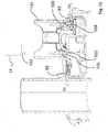
Figures 6 and 7 , thebowl 18 of the food processor receives thelid 20. The bowl also contains, centrally and on the upper surface of the floor 26 a locating post, pin orstub shaft 50. The locatingpost 50 receives and locates the removablemain spindle 51 of the food processor. Thepost 50 has, adjacent the free end 52 a pair of radially extendingears 53 or a circumferential bead or other mechanical feature that cooperates with thespindle 51. Thespindle 51 has anexternal sleeve 54 that retains thecentral shaft 55. In the example ofFigures 6 and 7 , thespindle 51 can only be maintained in position on thepost 50 when thelid 20 is properly fitted to thebowl 18. As the lid is removed, acompression spring 56 within thespindle 51 acts to disengage thespindle 51 from thepost 50. In this example, thelid 20 hasmale bayonet components 57 and the interior rim of thebowl 18 hasfemale bayonet components 58. Thebayonet components rim 59 of thelid 18 is fully inserted and temporarily locked with respect to thebowl 18 once the lid is inserted and rotated into position particularly with respect to food processor lids that incorporate an integral gear box, the lid depicted (for example) inFigure 9 , because of the descendingrim 59 allows the bowl to have a greater effective volume for a given bowl size. This is because the volume between the lowest edge of the descendingrim 59 and the under surface of the top of the lid forms a void 59a rather than being occupied with the operational components of a gear box that is fully contained within the lid structure. - As shown in
Figures 6-9 , thelid 20 has arecess 23 for receiving thebase 23a of thegear box 24. The vertical depth of therecess 23 is approximately the same as the vertical thickness of the base of thegear box 23a. In general, the gear box will fit snugly within therecess 23 wherein it is further stabilised by the connection between the femalestyle output coupling 60 of the gear box and the male component of the rotatingintermediate coupling 61 located within therecess 23. The upper end ormale component 62 of theintermediate coupling 61 fits within thefemale coupling component 60 located on an underside of thegear box 24. Theintermediate coupling 63 extends through an opening in the floor of the recess. The through opening is in alignment with the rotational center of thespindle 51 and thus located in the center of the lid, but not necessarily the center of the recess. Theintermediate coupling 61 also has a female end with achamfered surround 63 that receives and couples to themale tip 64 of thespindle 51. The dimensions and configuration of thetip 64 are such that the tip cannot be engaged by or rotated by either thefemale coupling component 60 of the gear box or theoutput spindle 40 of thehandle component 14 of the stick mixer. The rotatingimmediate coupling 61 is optionally permanently retained by the recess in the lid. The lower surface of therecess 23 may also have moulded into it or otherwise support one or more upstanding locator or stabilising fingers 65 (see alsoitem 112 inFigure 12 ). This optional locator finger orfingers 65 engages a cooperating recess orslot 66 formed on an under surface of thegear box 24. - As shown in
Figure 8 , an undersurface 80 of thegear box 24 may have a recess ordepression 81 for receiving and locating acircumferential shoulder 82 formed around themale portion 62 of theintermediate coupling 61. The locations of therecess 81 andshoulder 82 may be reversed. The cooperation between therecess 81 and theshoulder 82 can contribute to the stability of the gear box when it is within the recess. In this example, themale portion 62 comprises an array of five splines. Thefemale coupling component gear box 80 has cooperating splines that engage with themale portion 62 of theintermediate coupling 61. As shown inFigure 9 , thefemale component 63 of theintermediate coupling 61 comprises three splines adapted to couple with the cooperatingtip 64 of the food processor'smain spindle 51. The female component and the through opening that receives it, are in the middle or center of the lid, even though the gearbox need not be central to the lid. Because the number of splines on the tip of thespindle 64 is different than the number of splines in thefemale component gear box 80 and thespindle 51. Direct interconnection between thegear box coupling 83 and the tip of thespindle 64 can be prevented in other ways. Suitable ways or preventing this interconnection include: making the number of splines different on the gear box and on thespindle tip 64, making the size of thecoupling components coupling 83 and the tip of thespindle 64. Also, the connection between thespindle tip 64 and the female coupling component. 63 of the intermediate coupling is only stable when the components are both vertical. This is because the tip of thespindle 64 is rounded or in the form of a rounded bulb and will fall, roll or spill out of the female coupling component. 63 of the intermediate coupling if the spindle and gear box are inclined and the spindle is not restrained at both ends by the intermediate coupling andstub shaft 50 by virtue of being installed into the bowl correctly. - As previously mentioned, the previously illustrated and describes examples contemplate that the gear box may be firmly retained within the lid's
recess 23 by virtue of their cooperating shapes and sizes as well as the engagement between the female coupling component of the gear box and the male component of the intermediate coupling. However, it may be desirable to add additional mechanical stability to the interconnection between the gear box and the recess. Examples of further mechanically stabilising the gear box within the recess are depicted, by way of example, inFigures 10-17 . - As shown in
Figure 10 , the exterior surface of the gear box comprises a pair of opposedmechanical button mechanical clip clip compression spring surface 96 that causes a retraction of the clip as it is inserted through the mouth opening of therecess 23. Anopposite chamfer 97 located adjacent to and above theslot 98 that receives the clip, promotes the retraction of the clip during insertion. Squeezing thebuttons -
Figure 10 also illustrates that thecentral bore 106 of the female coupling component 83 (associated with an underside of the gear box 80) can contain anejection plunger 107 that is biased or urged downwardly by acompression spring 108. As the lid is removed and the compression on the spindle tip is relieved, theplunger 107 ejects the tip of the spindle from thefemale coupling component 83. In this example, theplunger 107 comprises a disc-like head 109 that is attached to acentral stub shaft 115 about which thespring 108 is located. Note that thefemale coupling component 83 and the opening in the lid that receives it are in the middle of the lid so as to align with the spindle and rotational center of the bowl that the spindle is in. - Anther way of retracting the opposing clips 92, 93 is shown in
Figure 11 . In this embodiment, a ring shaped or one or more crescent shapedplatforms 100 are located at and preferably flush with the base of thevertical collar 101 of the gear box. When thehandle component 14 is inserted into thecollar 101, a downward extendinglip 102 drives the platform orplatforms 100 downward or toward the bowl of the food processor. Integral with theplatform 100, and located beneath it, are a pair of horizontal extendingpins platform 100 thus causes vertical movement of the pins, 103, 104. The pins ride in aninclined slot 105 formed at one end of eachclip handle portion 14 is removed, theplatform 100 returns to its original extended position and thus causes a retraction of the associated clip. - As shown in
Figure 12 , an underside of the gear box comprises one or more optional pockets or recesses 110. Each pocket orrecess 110 has a protrusion, bead orlip 111. The protrusion orprotrusions 111 each cooperate with an optional flexible andupstanding finger 112 that extends upwardly from the interior floor area of therecess 23. Downward pressure on the gear box is enough to flex thefingers 112 allowing the passage of theprotrusion 111 past a cooperatingprotrusion 113 formed adjacent to a free end of thefinger 112. It will be understood that in the illustrated example ofFigure 12 , both theprotrusion 111 and theco-operating protrusion 113 are generally symmetrical about a horizontal plane. It will also be understood that the finger may be provided as either outward or inward facing and that the finger can be either formed on the floor of the recess 23 (extending into apocket 110 on the gear box) or on the gear box, extending downward into a pocket formed downwardly into the floor of therecess 23. It will be understood that the shape of the finger nor the exact shape of theprotrusions flexible finger 112 andco-operating protrusion 111 is that it provides tactile or haptic feedback to the user, indicating that the gearbox is properly seated within thegearbox receiving recess 23. In the particular example ofFigure 12 , theflexible fingers 112 are both carried by an optionallyseparate platform 114. Theouter extremity 115 of theplatform 114 is larger than theopening 116 in the floor area of therecess 23 above which the fingers are located. Theopening 116 allows the platform andfingers platform 114 has apermanent locking detail 117 comprising atapered head 118 that flexes past the edges of theopening 116, then locking theedge 119 of theopening 116 onto or into a gap formed between thehead 118 and theplatform 114. This way of inserting the platforms and fingers after the manufacture of therecess 23 provides for ease of manufacturing and cost saving. In order to cover and make hygienic the attachment between theplatform 114 and therecess 23, theattachment detail 117 is covered by an optionalprotective cap 119a. The exterior edges of thecap 119a completely cover the attachment details 117, theopening 116 and the platform. 114. - As shown in
Figure 13 , thegear box assembly 120 comprises abase portion 121. Thelower corners 122 of the base 123 are radiused 124. Thevertical collar 125 that retains the handle component is off centre with respect to the base. Accordingly, the gear box assembly loosely resembles a foot. With reference toFigures 13-17 , the longer portion of the base (to the left of thecollar 125 is referred to as the "toe" 126 of the gear box assembly. That portion opposite thetoe 126 with respect to the collar is referred to as the "heel" 127. The upper surface of the base of the gear box has a depression or step down 128 that fits below ashelf 129 that extends into themouth area 130 of the recess in the lid. Thus, the toe can be inserted under theshelf 129 and retained by the shelf. The heel of the base incorporates aclip 131 that is retracted by pushing amechanical button 132. The button is biased into an extended position by a compression spring or other form ofresilient bias member 133. As with previous examples, the underside of clip is chamfered 134 so that it can be driven into its receiving slot in the recess without depressing thebutton 132. However, pressing the button will retract the clip and thereby allow the gear box assembly to be with drawn from the recess. - With respect to
Figure 14 , the location of theshelf 129 andclip 134 are reversed. Thus, the heel incorporates the depression orrecess 128 and the toe incorporates the retractable clip, a mechanical slidingbutton 135 and thecompression spring 136. In this example, the slide orbutton 135 is mounted on an upper surface, above thecompression spring 136. - With reference to 15, the gear box assembly is provided, in the region of the
toe 140 with a recess ordepression 141 that is accommodated below ashelf 142 formed adjacent to thefeed tube 143, the shelf extending into the mouth area of the recess formed in the lid, as previously described. In order to further stabilise the gear box within the recess and to inhibit the migration of food in this area, an outer periphery of the body of the gear box may be provided with acircumferential groove 144 that locates and restrains an O-ring type seal 145. - As shown in
Figure 16 , the circumferential walls of the gear box are provided with one or more lips, ribs orprotrusions 150 that can move past but that are retained by cooperatingprotrusions 151 formed on the interior side walls of therecess 152. In this way, the gear box assembly can be inserted and retained and removed without the need for mechanical buttons or springs. - As shown in
Figure 17 , the gear box may incorporate a pair of opposed, slidingclips 160, each having chamfered undersurfaces 161. Theclips clip bodies 163 that extend toward each other. Eachclip body 163 terminates in aslot 164. Theslots 164 overlie each other. A tapered or space-like member 165 extends through bothslots 163. The spade-like member 165 is mechanically attached to auser activatable button 166. Accordingly, depressing thebutton 166 causes the space-like member to further penetrate theslots 164, causing the tips of the clips to retract. When thebutton 166 is released, springs urge the clip bodies away from each other, thus returning the clip bodies to their resting or fully extended position. This allows a pair of opposing clips to be activated and deactivated with asingle button 166. - As shown in
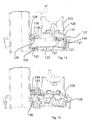
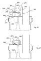
Figures 18, 19 and19a , a spindle 180 of a stick mixer driven food processor is driven from the top of the spindle by the removable gear box. The bottom of the spindle 180 is supported for rotation about a centrally locatedstub shaft 181 that is affixed to the center or rotational center of a lower surface of thefood processor bowl 182. The stub shaft has one or moreprotruding ears 183 that are located between the tip and the base of thestub shaft 181. The lowermost portion of the spindle 180 comprises askirt 184 within which is permanently mounted aflange 185 to which is affixed afemale spline component 186. Thefemale spline component 186 has radially extendingrecesses 187 that are adapted to engage the one ormore ears 183. As shown inFigure 18 , thehemispherical tip 188 of thestub shaft 181 engages a sliding andreciprocating locator 189. The locator has ahemispherical recess 190 extending upward from a lower extremity for receiving thetip 188 of the stub shaft. Thelocator 189 is urged downwardly by acompression spring 191. When the spindle 180 is captured between thestub shaft 181 and the lid's couple, the spindle is free to rotate relative to thebase 182.Figure 19 illustrates the disconnection between thegears 183 and the splines or recesses that are in a fixed orientation relative to the main body of the spindle. When the lid is removed, thelocator 189 is urged by thespring 191 downward. This has the effect of lifting theskirt 184 of the spindle above thebase surface 182. This causes an engagement between theears 183 and therecesses 187. This effectively rotationally locks the spindle relative to thestub shaft 181, thus preventing any blade attached to the spindle from rotating when the lid is removed. - As shown in
Figure 19a , thereciprocating locator 189 comprises anupper pocket 193 for receiving the lower end of thecompression spring 191. Thelower extent 194 of thelocator 189 further comprises acircumferential groove 195 for receiving apolymeric seal 196. Theseal 196 inhibits migration of undesirable foods or liquids into the area above theseal 196. Asecond seal 197 is located within theflange 185 and extends between the flange andspline component seal 197 prevents food from migrating into the internal cavity of the spindle.Figure 19a also illustrates thevertical splines 199 located below the vertically slotted coupling or tip 200 of the spindle. Thevertical splines 199 are for engaging the various blades and accessories associated with a spindle. - As shown in
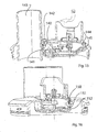
Figure 20 , therecess 201 in thelid 202 of the food processor further comprises alowermost opening 203 for receiving the clip-inplatform 204 that supports the optionalupright locating fingers 65. Theplatform 204 has on its underside, aclipping rim 205 preferably formed with a enlarged buttapered head 206 that defines an at least partiallycircumferential slot 207 adapted to engage the rim of theopening 203. Theupright fingers 65 have roundedtips 207 and, in this example, inwardly directed beads or interference features 208.Figure 20 also illustrates theoptional cover 119a for covering the underside of theplatform 204 after it is installed.Figure 20 also illustrates the space, recess orpocket 209 formed between the upper surface of thelid 210 and the lower rim of thelid 211. Thispocket 209 effectively increases the capacity of the food processing bowl relative to those kinds of lids that incorporate an integral gear box. The lid also features anupper flange 212 below which is located a descendingrim 213 having acircumferential groove 214 for polymeric seal. In this example, male bayonet features 215 are located on the descendingrim 213. - As shown in
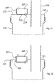
Figures 21 and 22 , there is considerable flexibility in how therecess 201 for receiving thegear box 220 is located relatively to thelid 221. InFigure 21 , therecess 201 is illustrated as comprising upright walls located on anupper surface 222 of the lid. In this example, thelower floor 223 of therecess 201 is contiguous with the flat upper surface of thelid 221. Because the lid'sspindle coupling 224 is central to thebowl 225 the feed tube is located eccentrically with respect to both the lid and bowl. - As shown in
Figure 22 , therecess 201 can be located partially above the lid'supper surface 221 while a portion of therecess 222 is located below theunderside 225 of the lid. - In previous examples, the rotating coupling that is mounted onto the lid and that transmits power between the gear box and spindle has been disclosed as having a male component for engaging with the gear box and a female component for engaging with the tip of the spindle. However,
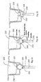
Figure 23 illustrates that thecoupling 230 can have amale component 231 for engaging with thegear box 232 and amale component 233 for engaging with afemale coupling component 234 formed on a tip of thespindle 235. It will also be noted that therecess 236 may be tapered to receive a similarly tapered side wall of thegear box 232. - As shown in
Figure 24 , thecoupling 240 may also be provided with afemale coupling component 241 for receiving a maleoutput coupling component 242 of thegear box 232. In this example, the lid'scoupling 240 has amale coupling component 243 for engaging afemale component 234 formed on a tip of thespindle 235. - As shown in
Figure 25 , the lid'scoupling 250 can have upper and lowerfemale coupling components gear box 253 and the tip of thespindle 254. - It will be appreciated that the aforementioned
intermediate coupling Figures 26 and 27 , thegear box 260 may be provided with a lock-outmechanism 261 that prevents power from being transmitted through the gear box, to thespindle 262 unless the gear box is correctly position within therecess 263 that receives it. As shown inFigures 26 and 27 , therecess 263 is formed on or integral with thelid 264 of the food processor. The lid has anopening 265, positioned above and in alignment with thespindle 262. The gear box'soutput coupling 266, whether male or female is located to cooperate with theopening 265 and thespindle 266 when thegear box 260 is correctly oriented in the recess. - The
interlock mechanism 261 prevents theoutput coupling 266 from delivering rotational power to the spindle unless asafety finger 267, which projects through the side wall of thegear box 260 is retracted. In the example ofFigures 26 and 27 , the retraction of thesafety finger 267 occurs when thegear box 260 is inserted, preferably fully inserted into therecess 263. Thesafety finger 267 may have acurved undersurface 268 to facilitate insertion of the safety finger past the upper rim of therecess 263. Preferably, thesafety finger 267 is biased outward by aspring 269 or other resilient means so that it returns to an extended position as shown inFigure 26 after removal from therecess 263. The gear box illustrated inFigures 26 and 27 may have one ormore safety fingers 268 so that engaging the power train between the input andoutput coupling 266 of thegear box 260 is made more difficult unless thegear box 260 is actually in therecess 263. Thesafety finger 268 can be located through an opening in either theside wall 270 orbottom wall 271 of thegear box 260. - More generally, it will be appreciated that when male and female relationships are disclosed with reference to cooperating mechanical parts such as coupling components and bayonet features, that the location of the male and female components and features can be reversed without consequence and that the recited relationships are based on example, convenience and conventional design practice in this art. Thus the terms male and female are essentially interchangeable in this specification, subject to the remainder of the practical and inventive teachings contained in the specification.
- Where male and female components such as clips and couplings are disclosed, it will be appreciated that the orientation of the male and female components such as couplings, threads and bayonet fittings can generally be reversed without adverse consequence. Their location as disclosed represents a preferred embodiment and should not be interpreted as literal requirements of the invention.
- While the present invention has been disclosed with reference to particular details of construction, these should be understood as having been provided by way of example and not as limitations to the scope of the invention.
Claims (12)
- A food processing lid device (20) with a reduction gear box (24), for use with a bowl (18) having a spindle (51), and a stick mixer handle (14), the handle (14) having an internal electric motor and a rotating output in the form of a first coupling (40), wherein the lid device includes:the lid (20) having a recess (23), the recess (23) having within it a through opening that is located centrally with respect to the lid; anda gearbox (24) having a second coupling for cooperating with the first coupling (40) so as to enable a coupling to the stick mixer handle (14);characterised in thatthe recess (23) is located on an upper surface of the lid;an intermediate coupling (61) is mounted in the lid (20) so as to be located in the through opening so as to enable a coupling to the spindle (51); andthe gear box (24) includes a third coupling (60) that cooperates with the intermediate coupling (61), whereby the gear box (24) is a separate component that is removeably received by the recess (23).
- The device of claim 1, wherein:
the intermediate coupling (61) is retained by the recess (23) and rotates relative to the recess. - The device of claim 2, wherein:
the first coupling (40) and the third coupling (60) do not have the same coupling configuration. - The device of claim 3, further comprising:
the stick mixer handle (14). - The device of claim 3, further comprising:
the bowl (18), the bowl having a bayonet engagement (58) with the lid. - The device of claim 1, wherein:
the gear box (24) comprises a mechanical button (90, 91) that, when the button (90, 91) is depressed, retracts a clip (92, 93), the clip cooperating with a slot (98) in the recess. - The device of claim 6, further comprising:
a mechanical second button (91, 90) that, when the second button (91, 90) is depressed, retracts a second clip (93, 92), the second clip (93, 92) cooperating with a second slot in the recess. - The device of claim 2, wherein:
an under surface (80) of the gearbox (24) has a recess (81) for receiving and locating the intermediate coupling (61). - The device of claim 2, wherein:an underside of the gear box (24) comprises one or more pockets (66, 110); andeach pocket (66, 110) cooperates with an upstanding flexible finger (65, 112) that extends upwardly from an interior floor area of the recess (23) so as to engage with it.
- The device of claim 4, wherein:
the gear box (24) comprises an upright collar (24, 101, 125) that is adapted to engage with and couple with the stick mixer. - The device of claim 2, wherein:
the intermediate coupling (61) has a female end with a chamfered surround (63). - An apparatus, comprising:the device of any one of claims 1 to 11,a stick mixer handle (14) having an internal electric motor and a rotating output in the form of a first coupling (40), the stick mixer handle (14) mounted in the recess (23), anda bowl (18) having a spindle (51),wherein the first coupling (40) is engaged with the second coupling, and the third coupling (60) is engaged with the intermediate coupling (61), andwherein the intermediate coupling (61) is engaged with the spindle (51), so that the stick mixer handle (14) drives the spindle (51).
Applications Claiming Priority (2)
| Application Number | Priority Date | Filing Date | Title |
|---|---|---|---|
| AU2012902402A AU2012902402A0 (en) | 2012-06-08 | Stick Mixer Driven Food Processor | |
| PCT/AU2013/000585 WO2013181692A1 (en) | 2012-06-08 | 2013-06-04 | Stick mixer driven food processor |
Publications (3)
| Publication Number | Publication Date |
|---|---|
| EP2858542A1 EP2858542A1 (en) | 2015-04-15 |
| EP2858542A4 EP2858542A4 (en) | 2016-07-27 |
| EP2858542B1 true EP2858542B1 (en) | 2019-01-09 |
Family
ID=49711196
Family Applications (1)
| Application Number | Title | Priority Date | Filing Date |
|---|---|---|---|
| EP13800077.3A Active EP2858542B1 (en) | 2012-06-08 | 2013-06-04 | Stick mixer driven food processor |
Country Status (5)
| Country | Link |
|---|---|
| US (1) | US9572457B2 (en) |
| EP (1) | EP2858542B1 (en) |
| CN (1) | CN104582548B (en) |
| AU (1) | AU2013271334B2 (en) |
| WO (1) | WO2013181692A1 (en) |
Families Citing this family (13)
| Publication number | Priority date | Publication date | Assignee | Title |
|---|---|---|---|---|
| WO2013181692A1 (en) * | 2012-06-08 | 2013-12-12 | Breville Pty Limited | Stick mixer driven food processor |
| CA2937038A1 (en) * | 2014-01-31 | 2015-08-06 | Spectrum Brands, Inc. | Chopping system |
| CN106361184B (en) * | 2016-11-16 | 2019-03-05 | 中山市峰行电器有限公司 | A kind of controllable temperature cooking machine convenient for assembly and disassembly cleaning |
| GB2565829B (en) * | 2017-08-24 | 2022-02-09 | Kenwood Ltd | Seal assembly for a kitchen appliance |
| DE102018207506B4 (en) | 2018-05-15 | 2020-10-15 | De'longhi Braun Household Gmbh | Household appliance for processing food with a splash guard |
| DE102018207505B4 (en) | 2018-05-15 | 2020-01-02 | De'longhi Braun Household Gmbh | Kitchen appliance base part and kitchen appliance with a kitchen appliance base part |
| WO2020075211A1 (en) * | 2018-10-09 | 2020-04-16 | Hamarneh Omar | Food processing device |
| DE102018220448B4 (en) | 2018-11-28 | 2023-01-05 | De'longhi Braun Household Gmbh | kitchen utensil |
| WO2020118224A1 (en) | 2018-12-06 | 2020-06-11 | Columbia Insurance Company | Modular appliance apparatus configured for multiple attachments |
| EP3733033B1 (en) * | 2019-04-30 | 2021-12-01 | Senur Elektrik Motorlari San. Ve Tic. A.S. | Lid device having a gear box for a food processor |
| US20220240721A1 (en) * | 2021-02-04 | 2022-08-04 | Black & Decker, Inc. | Modular hand-held kitchen applicance |
| USD1020365S1 (en) | 2022-05-09 | 2024-04-02 | Sharkninja Operating Llc | Blender attachment |
| EP4285796A1 (en) * | 2022-05-30 | 2023-12-06 | BSH Hausgeräte GmbH | Container cover of an electric household appliance, assembling method, and household appliance |
Family Cites Families (17)
| Publication number | Priority date | Publication date | Assignee | Title |
|---|---|---|---|---|
| DE1251479B (en) | 1964-11-26 | 1967-10-05 | Siemens-Electrogerate Gesellschaft mit beschrankter Haftung Berlin und München München | ELECTRIC HOUSEHOLD MACHINE FOR CUTTING, CHOPPING GRATING |
| DE2000171A1 (en) * | 1970-01-03 | 1971-07-08 | Suhl Elektrogeraete Veb K | Electric motor household machine for cutting, chopping, rubbing or the like. |
| US4049243A (en) * | 1976-07-19 | 1977-09-20 | Hyman Kramer | Blending and kneading apparatus |
| DE10151231C2 (en) * | 2001-10-17 | 2003-08-21 | Maweva Holding Ag Ltd Mettlen | Food processor for food preparation |
| US6814323B2 (en) * | 2002-06-07 | 2004-11-09 | Hamilton Beach/Proctor-Silex, Inc. | Food processor |
| ATE292927T1 (en) * | 2003-02-19 | 2005-04-15 | Betty Bossi Verlag Ag | HAND-DRIVEN DEVICE FOR CUTTING FOOD |
| US7229036B2 (en) * | 2004-02-18 | 2007-06-12 | Hamilton Beach/Proctor Silex, Inc. | Food processing appliance with indicator |
| US7028930B2 (en) * | 2004-02-19 | 2006-04-18 | Hamilton Beach/Proctor-Silex, Inc. | Kitchen appliance with a safety interlock |
| US7530510B2 (en) * | 2004-03-19 | 2009-05-12 | Hamilton Beach Brands, Inc. | Storage food processor |
| CN200991174Y (en) * | 2006-12-12 | 2007-12-19 | 律展企业股份有限公司 | Multifunction food cooking machine |
| CN101138466B (en) * | 2007-10-12 | 2010-06-09 | 潘豪瀚 | Food processor |
| CN201082133Y (en) | 2007-10-12 | 2008-07-09 | 潘豪瀚 | Food processor |
| US8157435B2 (en) * | 2009-03-11 | 2012-04-17 | Hamilton Beach Brands, Inc | Lid for a mixing device |
| EP2564745A1 (en) * | 2011-09-01 | 2013-03-06 | Koninklijke Philips Electronics N.V. | A lid for a food processor |
| US8814072B2 (en) * | 2011-11-30 | 2014-08-26 | Whirlpool Corporation | User-controlled adjustment mechanism for a food processing device |
| WO2013181692A1 (en) * | 2012-06-08 | 2013-12-12 | Breville Pty Limited | Stick mixer driven food processor |
| CN202932790U (en) * | 2012-12-12 | 2013-05-15 | 惠阳亚伦塑胶电器实业有限公司 | Hand-held heating stirring machine |
-
2013
- 2013-06-04 WO PCT/AU2013/000585 patent/WO2013181692A1/en active Application Filing
- 2013-06-04 EP EP13800077.3A patent/EP2858542B1/en active Active
- 2013-06-04 US US14/405,402 patent/US9572457B2/en active Active
- 2013-06-04 CN CN201380041199.6A patent/CN104582548B/en active Active
- 2013-06-04 AU AU2013271334A patent/AU2013271334B2/en active Active
Non-Patent Citations (1)
| Title |
|---|
| None * |
Also Published As
| Publication number | Publication date |
|---|---|
| CN104582548B (en) | 2017-06-27 |
| US20150164279A1 (en) | 2015-06-18 |
| CN104582548A (en) | 2015-04-29 |
| AU2013271334B2 (en) | 2017-03-02 |
| WO2013181692A8 (en) | 2014-07-03 |
| EP2858542A1 (en) | 2015-04-15 |
| WO2013181692A1 (en) | 2013-12-12 |
| EP2858542A4 (en) | 2016-07-27 |
| AU2013271334A1 (en) | 2015-01-15 |
| US9572457B2 (en) | 2017-02-21 |
Similar Documents
| Publication | Publication Date | Title |
|---|---|---|
| EP2858542B1 (en) | Stick mixer driven food processor | |
| US10463180B1 (en) | Candle decks and covers for cakes and cupcakes | |
| US7441944B2 (en) | Drinking extension for blender container | |
| CN203633964U (en) | Hand-held masher device | |
| CN102083596B (en) | Multifunctional cooking Preparation equipment and/or food continuous cutting device | |
| US7635101B1 (en) | Multi-grater | |
| US20210330129A1 (en) | Adapter between a disposable cup and a blender blade assembly | |
| US20070194032A1 (en) | Food processor bowl and food processor | |
| CN104441001B (en) | Food cutting attachment including multiple auxiliary cutting tools | |
| JP2015527143A (en) | Kitchen utensils placed in containers, kitchen utensils set with kitchen utensils and various functional units | |
| US9867503B2 (en) | Chopping system | |
| US8991734B2 (en) | Food chopper | |
| CN104441017B (en) | For food to be cut to blocking annex | |
| US20030205148A1 (en) | Anti-rotational cup holder | |
| WO2016168889A1 (en) | Potato peeler | |
| ES2267087T3 (en) | APPLIANCES FOR CULINARY PREPARATIONS. | |
| KR101620320B1 (en) | mixing machine | |
| CN105030098B (en) | Household cooking appliance including the detachable container being placed on shell can be moved by simple translation | |
| KR200458563Y1 (en) | The prop for hand blend | |
| EP2750566B1 (en) | An apparatus for preparing a food stuff | |
| CN215383441U (en) | Food processor convenient to operate | |
| NO157515B (en) | VALVE VALVE TURNING STOCK. | |
| CN210551557U (en) | Portable momordica grosvenori cutting device | |
| CN102415832A (en) | Device for fixing a receptacle or a lid of a household cooking appliance | |
| CN207186521U (en) | A kind of bean milling machine structure of coffee machine |
Legal Events
| Date | Code | Title | Description |
|---|---|---|---|
| PUAI | Public reference made under article 153(3) epc to a published international application that has entered the european phase |
Free format text: ORIGINAL CODE: 0009012 |
|
| 17P | Request for examination filed |
Effective date: 20150108 |
|
| AK | Designated contracting states |
Kind code of ref document: A1 Designated state(s): AL AT BE BG CH CY CZ DE DK EE ES FI FR GB GR HR HU IE IS IT LI LT LU LV MC MK MT NL NO PL PT RO RS SE SI SK SM TR |
|
| AX | Request for extension of the european patent |
Extension state: BA ME |
|
| DAX | Request for extension of the european patent (deleted) | ||
| RA4 | Supplementary search report drawn up and despatched (corrected) |
Effective date: 20160624 |
|
| RIC1 | Information provided on ipc code assigned before grant |
Ipc: A47J 43/04 20060101AFI20160620BHEP Ipc: A47J 44/00 20060101ALI20160620BHEP Ipc: A47J 44/02 20060101ALI20160620BHEP Ipc: A47J 43/044 20060101ALI20160620BHEP |
|
| GRAP | Despatch of communication of intention to grant a patent |
Free format text: ORIGINAL CODE: EPIDOSNIGR1 |
|
| STAA | Information on the status of an ep patent application or granted ep patent |
Free format text: STATUS: GRANT OF PATENT IS INTENDED |
|
| INTG | Intention to grant announced |
Effective date: 20180412 |
|
| GRAJ | Information related to disapproval of communication of intention to grant by the applicant or resumption of examination proceedings by the epo deleted |
Free format text: ORIGINAL CODE: EPIDOSDIGR1 |
|
| STAA | Information on the status of an ep patent application or granted ep patent |
Free format text: STATUS: REQUEST FOR EXAMINATION WAS MADE |
|
| GRAP | Despatch of communication of intention to grant a patent |
Free format text: ORIGINAL CODE: EPIDOSNIGR1 |
|
| STAA | Information on the status of an ep patent application or granted ep patent |
Free format text: STATUS: GRANT OF PATENT IS INTENDED |
|
| INTC | Intention to grant announced (deleted) | ||
| INTG | Intention to grant announced |
Effective date: 20180917 |
|
| GRAS | Grant fee paid |
Free format text: ORIGINAL CODE: EPIDOSNIGR3 |
|
| GRAA | (expected) grant |
Free format text: ORIGINAL CODE: 0009210 |
|
| STAA | Information on the status of an ep patent application or granted ep patent |
Free format text: STATUS: THE PATENT HAS BEEN GRANTED |
|
| AK | Designated contracting states |
Kind code of ref document: B1 Designated state(s): AL AT BE BG CH CY CZ DE DK EE ES FI FR GB GR HR HU IE IS IT LI LT LU LV MC MK MT NL NO PL PT RO RS SE SI SK SM TR |
|
| REG | Reference to a national code |
Ref country code: GB Ref legal event code: FG4D |
|
| REG | Reference to a national code |
Ref country code: CH Ref legal event code: EP Ref country code: AT Ref legal event code: REF Ref document number: 1086281 Country of ref document: AT Kind code of ref document: T Effective date: 20190115 |
|
| REG | Reference to a national code |
Ref country code: DE Ref legal event code: R096 Ref document number: 602013049638 Country of ref document: DE |
|
| REG | Reference to a national code |
Ref country code: IE Ref legal event code: FG4D |
|
| REG | Reference to a national code |
Ref country code: NL Ref legal event code: MP Effective date: 20190109 |
|
| REG | Reference to a national code |
Ref country code: LT Ref legal event code: MG4D |
|
| PG25 | Lapsed in a contracting state [announced via postgrant information from national office to epo] |
Ref country code: NL Free format text: LAPSE BECAUSE OF FAILURE TO SUBMIT A TRANSLATION OF THE DESCRIPTION OR TO PAY THE FEE WITHIN THE PRESCRIBED TIME-LIMIT Effective date: 20190109 |
|
| REG | Reference to a national code |
Ref country code: AT Ref legal event code: MK05 Ref document number: 1086281 Country of ref document: AT Kind code of ref document: T Effective date: 20190109 |
|
| PG25 | Lapsed in a contracting state [announced via postgrant information from national office to epo] |
Ref country code: ES Free format text: LAPSE BECAUSE OF FAILURE TO SUBMIT A TRANSLATION OF THE DESCRIPTION OR TO PAY THE FEE WITHIN THE PRESCRIBED TIME-LIMIT Effective date: 20190109 Ref country code: SE Free format text: LAPSE BECAUSE OF FAILURE TO SUBMIT A TRANSLATION OF THE DESCRIPTION OR TO PAY THE FEE WITHIN THE PRESCRIBED TIME-LIMIT Effective date: 20190109 Ref country code: PT Free format text: LAPSE BECAUSE OF FAILURE TO SUBMIT A TRANSLATION OF THE DESCRIPTION OR TO PAY THE FEE WITHIN THE PRESCRIBED TIME-LIMIT Effective date: 20190509 Ref country code: LT Free format text: LAPSE BECAUSE OF FAILURE TO SUBMIT A TRANSLATION OF THE DESCRIPTION OR TO PAY THE FEE WITHIN THE PRESCRIBED TIME-LIMIT Effective date: 20190109 Ref country code: PL Free format text: LAPSE BECAUSE OF FAILURE TO SUBMIT A TRANSLATION OF THE DESCRIPTION OR TO PAY THE FEE WITHIN THE PRESCRIBED TIME-LIMIT Effective date: 20190109 Ref country code: FI Free format text: LAPSE BECAUSE OF FAILURE TO SUBMIT A TRANSLATION OF THE DESCRIPTION OR TO PAY THE FEE WITHIN THE PRESCRIBED TIME-LIMIT Effective date: 20190109 Ref country code: NO Free format text: LAPSE BECAUSE OF FAILURE TO SUBMIT A TRANSLATION OF THE DESCRIPTION OR TO PAY THE FEE WITHIN THE PRESCRIBED TIME-LIMIT Effective date: 20190409 |
|
| PG25 | Lapsed in a contracting state [announced via postgrant information from national office to epo] |
Ref country code: IS Free format text: LAPSE BECAUSE OF FAILURE TO SUBMIT A TRANSLATION OF THE DESCRIPTION OR TO PAY THE FEE WITHIN THE PRESCRIBED TIME-LIMIT Effective date: 20190509 Ref country code: GR Free format text: LAPSE BECAUSE OF FAILURE TO SUBMIT A TRANSLATION OF THE DESCRIPTION OR TO PAY THE FEE WITHIN THE PRESCRIBED TIME-LIMIT Effective date: 20190410 Ref country code: RS Free format text: LAPSE BECAUSE OF FAILURE TO SUBMIT A TRANSLATION OF THE DESCRIPTION OR TO PAY THE FEE WITHIN THE PRESCRIBED TIME-LIMIT Effective date: 20190109 Ref country code: BG Free format text: LAPSE BECAUSE OF FAILURE TO SUBMIT A TRANSLATION OF THE DESCRIPTION OR TO PAY THE FEE WITHIN THE PRESCRIBED TIME-LIMIT Effective date: 20190409 Ref country code: LV Free format text: LAPSE BECAUSE OF FAILURE TO SUBMIT A TRANSLATION OF THE DESCRIPTION OR TO PAY THE FEE WITHIN THE PRESCRIBED TIME-LIMIT Effective date: 20190109 Ref country code: HR Free format text: LAPSE BECAUSE OF FAILURE TO SUBMIT A TRANSLATION OF THE DESCRIPTION OR TO PAY THE FEE WITHIN THE PRESCRIBED TIME-LIMIT Effective date: 20190109 |
|
| REG | Reference to a national code |
Ref country code: DE Ref legal event code: R097 Ref document number: 602013049638 Country of ref document: DE |
|
| PG25 | Lapsed in a contracting state [announced via postgrant information from national office to epo] |
Ref country code: CZ Free format text: LAPSE BECAUSE OF FAILURE TO SUBMIT A TRANSLATION OF THE DESCRIPTION OR TO PAY THE FEE WITHIN THE PRESCRIBED TIME-LIMIT Effective date: 20190109 Ref country code: IT Free format text: LAPSE BECAUSE OF FAILURE TO SUBMIT A TRANSLATION OF THE DESCRIPTION OR TO PAY THE FEE WITHIN THE PRESCRIBED TIME-LIMIT Effective date: 20190109 Ref country code: AL Free format text: LAPSE BECAUSE OF FAILURE TO SUBMIT A TRANSLATION OF THE DESCRIPTION OR TO PAY THE FEE WITHIN THE PRESCRIBED TIME-LIMIT Effective date: 20190109 Ref country code: SK Free format text: LAPSE BECAUSE OF FAILURE TO SUBMIT A TRANSLATION OF THE DESCRIPTION OR TO PAY THE FEE WITHIN THE PRESCRIBED TIME-LIMIT Effective date: 20190109 Ref country code: AT Free format text: LAPSE BECAUSE OF FAILURE TO SUBMIT A TRANSLATION OF THE DESCRIPTION OR TO PAY THE FEE WITHIN THE PRESCRIBED TIME-LIMIT Effective date: 20190109 Ref country code: EE Free format text: LAPSE BECAUSE OF FAILURE TO SUBMIT A TRANSLATION OF THE DESCRIPTION OR TO PAY THE FEE WITHIN THE PRESCRIBED TIME-LIMIT Effective date: 20190109 Ref country code: DK Free format text: LAPSE BECAUSE OF FAILURE TO SUBMIT A TRANSLATION OF THE DESCRIPTION OR TO PAY THE FEE WITHIN THE PRESCRIBED TIME-LIMIT Effective date: 20190109 Ref country code: RO Free format text: LAPSE BECAUSE OF FAILURE TO SUBMIT A TRANSLATION OF THE DESCRIPTION OR TO PAY THE FEE WITHIN THE PRESCRIBED TIME-LIMIT Effective date: 20190109 |
|
| PLBE | No opposition filed within time limit |
Free format text: ORIGINAL CODE: 0009261 |
|
| STAA | Information on the status of an ep patent application or granted ep patent |
Free format text: STATUS: NO OPPOSITION FILED WITHIN TIME LIMIT |
|
| PG25 | Lapsed in a contracting state [announced via postgrant information from national office to epo] |
Ref country code: SM Free format text: LAPSE BECAUSE OF FAILURE TO SUBMIT A TRANSLATION OF THE DESCRIPTION OR TO PAY THE FEE WITHIN THE PRESCRIBED TIME-LIMIT Effective date: 20190109 |
|
| 26N | No opposition filed |
Effective date: 20191010 |
|
| PG25 | Lapsed in a contracting state [announced via postgrant information from national office to epo] |
Ref country code: MC Free format text: LAPSE BECAUSE OF FAILURE TO SUBMIT A TRANSLATION OF THE DESCRIPTION OR TO PAY THE FEE WITHIN THE PRESCRIBED TIME-LIMIT Effective date: 20190109 |
|
| REG | Reference to a national code |
Ref country code: CH Ref legal event code: PL |
|
| PG25 | Lapsed in a contracting state [announced via postgrant information from national office to epo] |
Ref country code: SI Free format text: LAPSE BECAUSE OF FAILURE TO SUBMIT A TRANSLATION OF THE DESCRIPTION OR TO PAY THE FEE WITHIN THE PRESCRIBED TIME-LIMIT Effective date: 20190109 |
|
| REG | Reference to a national code |
Ref country code: BE Ref legal event code: MM Effective date: 20190630 |
|
| PG25 | Lapsed in a contracting state [announced via postgrant information from national office to epo] |
Ref country code: TR Free format text: LAPSE BECAUSE OF FAILURE TO SUBMIT A TRANSLATION OF THE DESCRIPTION OR TO PAY THE FEE WITHIN THE PRESCRIBED TIME-LIMIT Effective date: 20190109 |
|
| PG25 | Lapsed in a contracting state [announced via postgrant information from national office to epo] |
Ref country code: IE Free format text: LAPSE BECAUSE OF NON-PAYMENT OF DUE FEES Effective date: 20190604 |
|
| PG25 | Lapsed in a contracting state [announced via postgrant information from national office to epo] |
Ref country code: CH Free format text: LAPSE BECAUSE OF NON-PAYMENT OF DUE FEES Effective date: 20190630 Ref country code: BE Free format text: LAPSE BECAUSE OF NON-PAYMENT OF DUE FEES Effective date: 20190630 Ref country code: LI Free format text: LAPSE BECAUSE OF NON-PAYMENT OF DUE FEES Effective date: 20190630 Ref country code: LU Free format text: LAPSE BECAUSE OF NON-PAYMENT OF DUE FEES Effective date: 20190604 |
|
| PG25 | Lapsed in a contracting state [announced via postgrant information from national office to epo] |
Ref country code: CY Free format text: LAPSE BECAUSE OF FAILURE TO SUBMIT A TRANSLATION OF THE DESCRIPTION OR TO PAY THE FEE WITHIN THE PRESCRIBED TIME-LIMIT Effective date: 20190109 |
|
| PG25 | Lapsed in a contracting state [announced via postgrant information from national office to epo] |
Ref country code: MT Free format text: LAPSE BECAUSE OF FAILURE TO SUBMIT A TRANSLATION OF THE DESCRIPTION OR TO PAY THE FEE WITHIN THE PRESCRIBED TIME-LIMIT Effective date: 20190109 Ref country code: HU Free format text: LAPSE BECAUSE OF FAILURE TO SUBMIT A TRANSLATION OF THE DESCRIPTION OR TO PAY THE FEE WITHIN THE PRESCRIBED TIME-LIMIT; INVALID AB INITIO Effective date: 20130604 |
|
| PG25 | Lapsed in a contracting state [announced via postgrant information from national office to epo] |
Ref country code: MK Free format text: LAPSE BECAUSE OF FAILURE TO SUBMIT A TRANSLATION OF THE DESCRIPTION OR TO PAY THE FEE WITHIN THE PRESCRIBED TIME-LIMIT Effective date: 20190109 |
|
| PGFP | Annual fee paid to national office [announced via postgrant information from national office to epo] |
Ref country code: FR Payment date: 20230523 Year of fee payment: 11 Ref country code: DE Payment date: 20230502 Year of fee payment: 11 |
|
| PGFP | Annual fee paid to national office [announced via postgrant information from national office to epo] |
Ref country code: GB Payment date: 20230504 Year of fee payment: 11 |