EP2858282A2 - Dispositif de communication pour un véhicule ferroviaire, véhicule ferroviaire équipé d'un tel dispositif - Google Patents
Dispositif de communication pour un véhicule ferroviaire, véhicule ferroviaire équipé d'un tel dispositif Download PDFInfo
- Publication number
- EP2858282A2 EP2858282A2 EP20140185425 EP14185425A EP2858282A2 EP 2858282 A2 EP2858282 A2 EP 2858282A2 EP 20140185425 EP20140185425 EP 20140185425 EP 14185425 A EP14185425 A EP 14185425A EP 2858282 A2 EP2858282 A2 EP 2858282A2
- Authority
- EP
- European Patent Office
- Prior art keywords
- communication
- stage
- railway vehicle
- protection
- signals
- Prior art date
- Legal status (The legal status is an assumption and is not a legal conclusion. Google has not performed a legal analysis and makes no representation as to the accuracy of the status listed.)
- Granted
Links
Images


Classifications
-
- B—PERFORMING OPERATIONS; TRANSPORTING
- B61—RAILWAYS
- B61L—GUIDING RAILWAY TRAFFIC; ENSURING THE SAFETY OF RAILWAY TRAFFIC
- B61L15/00—Indicators provided on the vehicle or train for signalling purposes
- B61L15/0018—Communication with or on the vehicle or train
- B61L15/0027—Radio-based, e.g. using GSM-R
-
- H—ELECTRICITY
- H04—ELECTRIC COMMUNICATION TECHNIQUE
- H04B—TRANSMISSION
- H04B7/00—Radio transmission systems, i.e. using radiation field
- H04B7/24—Radio transmission systems, i.e. using radiation field for communication between two or more posts
- H04B7/26—Radio transmission systems, i.e. using radiation field for communication between two or more posts at least one of which is mobile
- H04B7/2603—Arrangements for wireless physical layer control
- H04B7/2606—Arrangements for base station coverage control, e.g. by using relays in tunnels
-
- H—ELECTRICITY
- H04—ELECTRIC COMMUNICATION TECHNIQUE
- H04K—SECRET COMMUNICATION; JAMMING OF COMMUNICATION
- H04K3/00—Jamming of communication; Counter-measures
- H04K3/40—Jamming having variable characteristics
- H04K3/42—Jamming having variable characteristics characterized by the control of the jamming frequency or wavelength
-
- H—ELECTRICITY
- H04—ELECTRIC COMMUNICATION TECHNIQUE
- H04K—SECRET COMMUNICATION; JAMMING OF COMMUNICATION
- H04K3/00—Jamming of communication; Counter-measures
- H04K3/40—Jamming having variable characteristics
- H04K3/43—Jamming having variable characteristics characterized by the control of the jamming power, signal-to-noise ratio or geographic coverage area
-
- H—ELECTRICITY
- H04—ELECTRIC COMMUNICATION TECHNIQUE
- H04K—SECRET COMMUNICATION; JAMMING OF COMMUNICATION
- H04K3/00—Jamming of communication; Counter-measures
- H04K3/80—Jamming or countermeasure characterized by its function
- H04K3/84—Jamming or countermeasure characterized by its function related to preventing electromagnetic interference in petrol station, hospital, plane or cinema
-
- B—PERFORMING OPERATIONS; TRANSPORTING
- B61—RAILWAYS
- B61L—GUIDING RAILWAY TRAFFIC; ENSURING THE SAFETY OF RAILWAY TRAFFIC
- B61L3/00—Devices along the route for controlling devices on the vehicle or train, e.g. to release brake or to operate a warning signal
- B61L3/02—Devices along the route for controlling devices on the vehicle or train, e.g. to release brake or to operate a warning signal at selected places along the route, e.g. intermittent control simultaneous mechanical and electrical control
- B61L3/08—Devices along the route for controlling devices on the vehicle or train, e.g. to release brake or to operate a warning signal at selected places along the route, e.g. intermittent control simultaneous mechanical and electrical control controlling electrically
- B61L3/12—Devices along the route for controlling devices on the vehicle or train, e.g. to release brake or to operate a warning signal at selected places along the route, e.g. intermittent control simultaneous mechanical and electrical control controlling electrically using magnetic or electrostatic induction; using radio waves
- B61L3/125—Devices along the route for controlling devices on the vehicle or train, e.g. to release brake or to operate a warning signal at selected places along the route, e.g. intermittent control simultaneous mechanical and electrical control controlling electrically using magnetic or electrostatic induction; using radio waves using short-range radio transmission
-
- H—ELECTRICITY
- H04—ELECTRIC COMMUNICATION TECHNIQUE
- H04B—TRANSMISSION
- H04B1/00—Details of transmission systems, not covered by a single one of groups H04B3/00 - H04B13/00; Details of transmission systems not characterised by the medium used for transmission
- H04B1/02—Transmitters
- H04B1/04—Circuits
- H04B1/0475—Circuits with means for limiting noise, interference or distortion
-
- H—ELECTRICITY
- H04—ELECTRIC COMMUNICATION TECHNIQUE
- H04K—SECRET COMMUNICATION; JAMMING OF COMMUNICATION
- H04K2203/00—Jamming of communication; Countermeasures
- H04K2203/10—Jamming or countermeasure used for a particular application
- H04K2203/18—Jamming or countermeasure used for a particular application for wireless local area networks or WLAN
-
- H—ELECTRICITY
- H04—ELECTRIC COMMUNICATION TECHNIQUE
- H04K—SECRET COMMUNICATION; JAMMING OF COMMUNICATION
- H04K2203/00—Jamming of communication; Countermeasures
- H04K2203/10—Jamming or countermeasure used for a particular application
- H04K2203/22—Jamming or countermeasure used for a particular application for communication related to vehicles
-
- H—ELECTRICITY
- H04—ELECTRIC COMMUNICATION TECHNIQUE
- H04W—WIRELESS COMMUNICATION NETWORKS
- H04W84/00—Network topologies
- H04W84/02—Hierarchically pre-organised networks, e.g. paging networks, cellular networks, WLAN [Wireless Local Area Network] or WLL [Wireless Local Loop]
- H04W84/10—Small scale networks; Flat hierarchical networks
- H04W84/12—WLAN [Wireless Local Area Networks]
Definitions
- the present invention relates to a communication device for a railway vehicle, of the type comprising a wireless communication stage for communicating with a control beacon in at least one spectral band of communication of a spectral range subdivided into several predetermined channels.
- the invention applies to the field of railway safety and more particularly, but not exclusively, to the safety of metropolitan transport.
- railway vehicles are equipped with a communication stage to communicate with control beacons arranged along the railway line.
- control beacons arranged along the railway line.
- Such tags allow for example a real-time control of rail traffic.
- the communication between the beacons and the communication stage is generally supported by radiofrequency electromagnetic waves, for example waves whose frequency is in the band 2400 MHz-2489.5 MHz, or beyond 5 GHz.
- radiofrequency electromagnetic waves for example waves whose frequency is in the band 2400 MHz-2489.5 MHz, or beyond 5 GHz.
- Such frequency ranges are generally not exclusively allocated, and are for example freely used by consumer mobile devices, such as mobile phones, tablets or laptops.
- An object of the invention is to provide a communication device to achieve better reliability and better availability of edge-ground communication.
- the subject of the invention is a communication device for a railway vehicle, of the aforementioned type, characterized in that it furthermore comprises a protection stage connected to a protection antenna, the protection stage being clean generating signals in at least one of the predetermined channels which at least partially overlap the or each communication spectral band, and the protection antenna being capable of radiating the signals generated towards at least one car of said railway vehicle.
- the third devices are no longer able to occupy the channels on which the protection stage emits signals.
- the invention also relates to a railway vehicle, characterized in that it comprises a communication device as defined above.
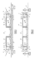
- the wireless communication device 5 illustrated by the figure 1 is disposed on board a railway vehicle 10 to communicate without contact with control beacons 15 arranged along a railway track 17 for the circulation of the railway vehicle 10.
- the communication between the communication device 5 and the control beacons 15 electromagnetic coupling via a waveguide 20, as shown in FIG. figure 1 , or by air through beacon antennas 25, as illustrated by the figure 2 .
- the control beacons 15 define space cells 26 along the track 17, each cell 26 being associated with a communication frequency.
- the communication frequencies are, for example, a low frequency F1 and a high frequency F2, F2 greater than F1, and are alternately assigned to the successive cells 26 along the railway line 17.
- the communication frequencies belong to the spectra defined by the IEEE 802.11 standard.
- the railway vehicle 10 comprises cars 27 for accommodating passengers, including passengers carrying mobile communication devices 28.
- the communication device 5 comprises a communication stage 30, a protection stage 35 and a protection antenna 40.
- the protective antenna 40 is disposed in a car 27 of the railway vehicle 10, in particular in an end car 45.
- the communication stage 30 is arranged in the same car 27 as the protection antenna 40.
- only the cars 27 of the railway vehicle 10 comprising a communication stage 30 are equipped with the protection antenna 40.
- the protective antenna 40 is for example a coaxial cable whose shield has been altered to allow the cable to radiate part of the electrical signals that pass through it.
- the communication stage 30 comprises a transmission-reception module 50 and a communication antenna 55.
- the communication stage further comprises filtering means 57 and screening means 58.
- the transceiver module 50 is able to communicate with the control beacons 15 via the communication antenna 55, by electromagnetic coupling between the communication antenna 55 and the waveguide 20, as illustrated by FIG. figure 1 , or by free propagation between the communication antenna 55 and the beacon antennas 25, as illustrated by the figure 2 .
- the filtering means 57 are suitable for performing a spectral filtering of a signal coming from the communication antenna 55.
- the screening means 58 are for example a box for electrically isolating the communication stage 30 of the protection antenna 40, while allowing communication between the communication stage 30 and the control beacons 15.
- the protection stage 35 comprises a first transmitter 60 for generating signals in a first spectral band B1, and a second transmitter 65 for generating signals in a second spectral band B2.
- the protection stage 35 further comprises a coupler 70.
- the signals generated by the first and second transmitters 60, 65 are preferably frames at layer 2 of the OSI model, as described in the IEEE 802.11 standard.
- the frames are composed of a header, a payload and terminated by a CRC ("Cyclic Redundancy Check") code which is used by the receiver to check if a frame has been correctly received.
- the frames are generated by transmitters 60 and 65 in sequence without interruption over time.
- the first transmitter 60 and the second transmitter 65 are connected to inputs of the coupler 70.
- the protection antenna 40 is electrically connected to an output of the coupler 70 to radiate a combination of the signals applied by the first transmitter 60 and the second transmitter 65 at the input of the coupler 70.
- the first and second transmitters 60, 65 comprise an Ethernet interface 100, a baseband processing unit 105 and a radio frequency module 110 connected in series.
- the Ethernet interface 100 is able to receive information relating to the configuration of the transmitters 60, 65, for example information coming from a ground system for managing rail traffic or a computer on board the railway vehicle 10. Such information is for example the value of the low frequency F1, the value of the high frequency F2, the power of the signals to be generated or the length of the frames to be generated.
- the baseband processing unit 105 is capable of providing a signal having baseband frames. More particularly, the baseband processing unit 105 is adapted to provide a signal having band frames based on the configuration information received by the Ethernet 100 interface.
- the radiofrequency module 110 is adapted to frequency transpose the signal provided by the baseband processing unit 105 to generate a radio frequency signal of frequency F1, F2 corresponding to the transmitter 60, 65 and which comprises said frames.
- An output 110S of the radiofrequency module 110 is connected to the protection antenna 45 to apply to said protection antenna 45 said radiofrequency signal.
- the baseband processing unit 105 is also adapted to receive, from the Ethernet interface 100, the information relating to the value of the frequencies F1, F2. As illustrated by figure 5 , the baseband processing unit 105 then comprises an output 105S connected to an input 110E of the radio frequency module 110 for controlling the frequency of transposition of the signal supplied by the baseband processing unit 105, said transposition frequency being equal to the frequency F1, F2.
- the communication device 5 whose operation is illustrated by the Figures 3 and 4 operates in the 2400 MHz-2489.5 MHz range. This range is subdivided into a plurality of predetermined channels according to the IEEE 802.11 standard. According to the IEEE 802.11 standard, the channels in the 2400 MHz-2489.5 MHz band have a width of 20 MHz.
- Each spectral band 75, 80 has a width of 5 MHz.
- the low frequency F1 here corresponds to the central frequency of the channel "2" of the 2400 MHz-2489.5 MHz band according to the IEEE 802.11 standard.
- the high frequency F2 here corresponds to the central frequency of the channel "13" of the band 2400 MHz-2489.5 MHz, according to the IEEE 802.11 standard.
- the spectral bands 75, 80 are chosen so that the corresponding channels do not interfere with at least one other channel of the multichannel spectral range.
- mobile devices 28 transmit in channel "1", channel “6” and channel “11" of the band 2400 MHz-2489.5 MHz, according to standard IEEE 802.11, designated respectively by references CH1, CH6 and CH11 in these figures.
- the channel “1" covers the low communication spectral band 75 and the channel “11” covers the high communication spectral band 80.
- the first spectral band B1 of the first transmitter 60 of the protection stage 35 is CH1 channel "1" according to the IEEE 802.11 standard.
- the second spectral band B2 of the second transmitter 65 of the protection stage 35 is the "11" CH11 channel according to the IEEE 802.11 standard.
- the filtering means 57 are, for example, a linear notch filter whose cut-off band extends from 2422 MHz to 2462 MHz, and is designated by the reference BC in these same figures.
- the communication stage 30 communicates with the successive control beacons 15, alternately at the frequency F1 and at the frequency F2, because of the successive passage of the control device. communication 5 of a cell 26 to the next cell 26.
- the protection means constituted by the protection stage 35 and the protection antenna 40, emit continuously (that is to say with a high repetition frequency and without transmission delay between the packets so as to occupy continuously a channel over time) frames in channel "1" CH1 and channel "11" CH11 to clutter these channels.
- the antenna 40 is preferably adapted to radiate signals mainly towards the end cars 45 of the railway vehicle, situated in the vicinity of the point of implantation of the antenna 40 on board the railway vehicle 10.
- the mobile devices 28 located in the end cars 45 can no longer use the channel "1" CH1, nor the channel "11" CH11. They can only use another channel, for example channel "6" CH6.
- the filtering means 57 filter the signals emitted by the mobile communication devices 28 in the channel "6" CH6.
- the screening means 58 attenuate the signals arriving at the communication stage 30 after having been transmitted by the protection stage 35 and radiated by the protection antenna 40.
- the power of the signals from the control beacons 15 and received by the communication stage 30 in each of the low 75 and high 80 communication bands is predominant in view of the power of the signals transmitted either by the mobile communication devices 28 in each case.
- channel "6" CH6 either by the first transmitter 60 in channel “1" CH1, or by the second transmitter 65 in channel "11" CH11.
Landscapes
- Engineering & Computer Science (AREA)
- Computer Networks & Wireless Communication (AREA)
- Signal Processing (AREA)
- Mechanical Engineering (AREA)
- Health & Medical Sciences (AREA)
- Electromagnetism (AREA)
- Oil, Petroleum & Natural Gas (AREA)
- Public Health (AREA)
- Chemical & Material Sciences (AREA)
- Physics & Mathematics (AREA)
- Train Traffic Observation, Control, And Security (AREA)
- Electric Propulsion And Braking For Vehicles (AREA)
- Mobile Radio Communication Systems (AREA)
Abstract
Description
- La présente invention concerne un dispositif de communication pour un véhicule ferroviaire, du type comprenant un étage de communication sans fil pour communiquer avec une balise de contrôle dans au moins une bande spectrale de communication d'une plage spectrale subdivisée en plusieurs canaux prédéterminés.
- L'invention s'applique au domaine de la sécurité ferroviaire et plus particulièrement, mais non exclusivement, à la sécurité des transports métropolitains.
- De façon classique, les véhicules ferroviaires sont équipés d'un étage de communication pour communiquer avec des balises de contrôle disposées le long de la voie ferrée. De telles balises permettent par exemple un contrôle en temps réel du trafic ferroviaire.
- La communication entre les balises et l'étage de communication a généralement pour support des ondes électromagnétiques radiofréquence, par exemple des ondes dont la fréquence se trouve dans la bande 2400 MHz-2489,5 MHz, ou au-delà de 5 GHz. De telles plages de fréquences ne sont généralement pas exclusivement allouées, et sont par exemple librement utilisées par des appareils mobiles grand public, tels que des téléphones portables, des tablettes ou encore des ordinateurs portables.
- La présence de tels appareils mobiles en nombre important à bord d'une voiture d'un véhicule ferroviaire, notamment à proximité de l'étage de communication, par exemple durant les heures de pointe, peut perturber, voire interrompre la communication entre l'étage de communication et les balises de contrôle. Les conditions de circulation en sécurité sont telles qu'en cas de rupture de la communication bord-sol, le véhicule ferroviaire doit s'immobiliser. Ainsi, la perturbation par les terminaux des voyageurs de la communication bord-sol a notamment pour effet l'interruption momentanée de la circulation du véhicule ferroviaire, ce qui a pour conséquence de réduire la qualité de service offerte aux usagers.
- Un but de l'invention est de proposer un dispositif de communication permettant d'atteindre une meilleure fiabilité et une meilleure disponibilité de la communication bord-sol.
- A cet effet, l'invention a pour objet un dispositif de communication pour un véhicule ferroviaire, du type précité, caractérisé en ce qu'il comporte en outre un étage de protection relié à une antenne de protection, l'étage de protection étant propre à générer des signaux dans au moins un des canaux prédéterminés qui recouvrent au moins en partie la ou chaque bande spectrale de communication, et l'antenne de protection étant propre à rayonner les signaux générés en direction d'au moins une voiture dudit véhicule ferroviaire.
- En effet, les appareils tiers, tels que décrits précédemment, ne sont plus en mesure d'occuper les canaux sur lesquels l'étage de protection émet des signaux.
- Suivant des modes particuliers de réalisation, l'invention présente l'une ou plusieurs des caractéristiques suivantes, prise(s) isolément ou selon toutes les combinaisons techniquement possibles :
- l'étage de protection est propre à émettre des signaux en continu au cours du temps dans le ou chaque canal prédéterminé ;
- la ou chaque bande de communication est plus étroite qu'un canal prédéterminé de la plage multicanaux ;
- l'étage de communication comporte des moyens d'écrantage propres à atténuer les signaux rayonnés par l'antenne de protection ;
- l'étage de communication comporte des moyens de filtrage propres à atténuer des signaux dont la fréquence appartient à des canaux prédéterminés qui ne recouvrent pas la ou chaque bande de communication ;
- les caractéristiques de la plage spectrale sont définies par la norme IEEE 802.11 ;
- l'étage de protection est propre à émettre des signaux qui comportent des trames de données au niveau de la couche 2 du modèle OSI.
- L'invention a aussi pour objet un véhicule ferroviaire, caractérisé en ce qu'il comprend un dispositif de communication tel que défini ci-dessus.
- Le véhicule ferroviaire peut comprendre l'une ou plusieurs des caractéristiques suivantes, prise(s) isolément ou suivant toute combinaison techniquement possible :
- l'antenne de protection est propre à rayonner en direction d'au moins une des voitures du véhicule ferroviaire qui sont situées au voisinage de l'implantation de l'étage de communication du dispositif de communication à bord du véhicule ferroviaire.
- L'invention sera mieux comprise à l'aide de la description qui va suivre, donnée uniquement à titre d'exemple et faite en se référant aux dessins annexés sur lesquels :
- la
figure 1 est un schéma d'un véhicule ferroviaire comprenant un dispositif de communication selon un premier mode de réalisation ; - la
figure 2 est un schéma d'un véhicule ferroviaire comprenant un autre dispositif de communication selon un second mode de réalisation ; - la
figure 3 est un spectre représentant schématiquement la puissance rayonnée dans certains canaux d'une plage spectrale, lorsque l'étage de protection du dispositif de communication de lafigure 1 ou de lafigure 2 est inactif ; - la
figure 4 est un spectre analogue au spectre de lafigure 3 , donné lorsque l'étage de protection est actif ; et - la
figure 5 est une représentation schématique d'un émetteur d'un dispositif de communication selon l'invention. - Le dispositif de communication 5 sans fil illustré par la
figure 1 est disposé à bord d'un véhicule ferroviaire 10 pour communiquer sans contact avec des balises de contrôle 15 disposées le long d'une voie ferrée 17 de circulation du véhicule ferroviaire 10. La communication entre le dispositif de communication 5 et les balises de contrôle 15 se fait par couplage électromagnétique via un guide d'onde 20, comme cela apparaît sur lafigure 1 , ou par voie aérienne par le biais d'antennes de balise 25, comme illustré par lafigure 2 . - Les balises de contrôle 15 définissent des cellules spatiales 26 le long de la voie ferrée 17, chaque cellule 26 étant associée à une fréquence de communication. Les fréquences de communication sont par exemple une fréquence basse F1 et une fréquence haute F2, F2 supérieure à F1, et sont affectées alternativement aux cellules 26 successives le long de la voie ferrée 17.
- Les fréquences de communication appartiennent aux spectres définis par la norme IEEE 802.11.
- Le véhicule ferroviaire 10 comporte des voitures 27 pour accueillir des passagers, notamment des passagers transportant des appareils mobiles de communication 28.
- Le dispositif de communication 5 comporte un étage de communication 30, un étage de protection 35 et une antenne de protection 40.
- L'antenne de protection 40 est disposée dans une voiture 27 du véhicule ferroviaire 10, en particulier dans une voiture d'extrémité 45. Avantageusement, l'étage de communication 30 est disposé dans la même voiture 27 que l'antenne de protection 40. De préférence, seules les voitures 27 du véhicule ferroviaire 10 comprenant un étage de communication 30 sont équipées de l'antenne de protection 40.
- L'antenne de protection 40 est par exemple un câble coaxial dont le blindage a été altéré pour permettre au câble de rayonner une partie des signaux électriques qui le traversent.
- L'étage de communication 30 comporte un module d'émission-réception 50 et une antenne de communication 55. L'étage de communication comporte en outre des moyens de filtrage 57 et des moyens d'écrantage 58.
- Le module d'émission-réception 50 est propre à communiquer avec les balises de contrôle 15 via l'antenne de communication 55, par couplage électromagnétique entre l'antenne de communication 55 et le guide d'onde 20, comme illustré par la
figure 1 , ou par propagation libre entre l'antenne de communication 55 et les antennes de balise 25, comme illustré par lafigure 2 . - Les moyens de filtrage 57 sont propres à effectuer un filtrage spectral d'un signal provenant de l'antenne de communication 55.
- Les moyens d'écrantage 58 sont par exemple un caisson pour isoler électriquement l'étage de communication 30 de l'antenne de protection 40, tout en permettant la communication entre l'étage de communication 30 et les balises de contrôle 15.
- L'étage de protection 35 comporte un premier émetteur 60 pour générer des signaux dans une première bande spectrale B1, et un deuxième émetteur 65 pour générer des signaux dans une deuxième bande spectrale B2. L'étage de protection 35 comporte en outre un coupleur 70.
- Les signaux générés par le premier et le deuxième émetteur 60, 65 sont de préférence des trames au niveau de la couche 2 du modèle OSI, tels que décrites dans la norme IEEE 802.11. Les trames sont composées d'un entête, d'une charge utile et terminés par un code CRC (« Cyclic Redundancy Check ») qui est utilisé par le récepteur pour vérifier si une trame a été correctement reçue. Les trames sont générées par les émetteurs 60 et 65 en séquence sans interruption au cours du temps.
- Le premier émetteur 60 et le deuxième émetteur 65 sont reliés à des entrées du coupleur 70.
- L'antenne de protection 40 est électriquement reliée à une sortie du coupleur 70 pour rayonner une combinaison des signaux appliqués par le premier émetteur 60 et le deuxième émetteur 65 en entrée du coupleur 70.
- Par exemple, comme illustré par la
figure 5 , le premier et le deuxième émetteurs 60, 65 comportent une interface Ethernet 100, une unité de traitement en bande de base 105 et un module radiofréquence 110 reliés en série. - L'interface Ethernet 100 est propre à recevoir des informations relatives à la configuration des émetteurs 60, 65, par exemple des informations provenant d'un système au sol de gestion du trafic ferroviaire ou d'un ordinateur embarqué à bord du véhicule ferroviaire 10. De telles informations sont par exemple la valeur de la fréquence basse F1, la valeur de la fréquence haute F2, la puissance des signaux à générer ou encore la longueur des trames à générer.
- L'unité de traitement en bande de base 105 est propre à fournir un signal comportant des trames en bande de base. Plus particulièrement, l'unité de traitement en bande de base 105 est propre à fournir un signal comportant des trames en bande de base dont les caractéristiques sont fonction des informations de configuration reçues par l'interface Ethernet 100.
- Le module radiofréquence 110 est propre à transposer en fréquence le signal fourni par l'unité de traitement en bande de base 105 pour générer un signal radiofréquence de fréquence F1, F2 correspondant à l'émetteur 60, 65 et qui comporte lesdites trames.
- Une sortie 110S du module radiofréquence 110 est reliée à l'antenne de protection 45 pour appliquer à ladite antenne de protection 45 ledit signal radiofréquence.
- Avantageusement, l'unité de traitement en bande de base 105 est également propre à recevoir, en provenance de l'interface Ethernet 100, les informations relatives à la valeur des fréquences F1, F2. Comme illustré par la
figure 5 , l'unité de traitement en bande de base 105 comporte alors une sortie 105S reliée à une entrée 110E du module radiofréquence 110 pour commander la fréquence de transposition du signal fourni par l'unité de traitement en bande de base 105, ladite fréquence de transposition étant égale à la fréquence F1, F2. - Le dispositif de communication 5 dont le fonctionnement est illustré par les
figures 3 et 4 opère dans la plage 2400 MHz-2489,5 MHz. Cette plage est subdivisée en une pluralité de canaux prédéterminés conformément à la norme IEEE 802.11. Selon la norme IEEE 802.11, les canaux de la bande 2400 MHz-2489,5 MHz ont une largeur de 20 MHz. - L'étage de communication 30 est propre à émettre et recevoir des signaux dans une bande spectrale de communication basse 75 et dans une bande spectrale de communication haute 80, centrées respectivement sur la fréquence basse F1 = 2417 MHz, et sur la fréquence haute F2 = 2472 MHz. Chaque bande spectrale 75, 80 a une largeur de 5 MHz.
- La fréquence basse F1 correspond ici à la fréquence centrale du canal « 2 » de la bande 2400 MHz-2489,5 MHz selon la norme IEEE 802.11.
- La fréquence haute F2 correspond ici à la fréquence centrale du canal « 13 » de la bande 2400 MHz-2489,5 MHz, selon la norme IEEE 802.11.
- Avantageusement, les bandes spectrales 75, 80 sont choisies de sorte que les canaux correspondants n'interfèrent pas avec au moins un autre canal de la plage spectrale multicanaux.
- Généralement, les appareils mobiles 28 émettent dans le canal « 1 », le canal « 6 » et le canal « 11 » de la bande 2400 MHz-2489,5 MHz, selon la norme IEEE 802.11, désignés respectivement par les références CH1, CH6 et CH11 sur ces figures.
- Ainsi, le canal « 1 » recouvre la bande spectrale de communication basse 75 et le canal « 11 » recouvre la bande spectrale de communication haute 80.
- La première bande spectrale B1 du premier émetteur 60 de l'étage de protection 35 est le canal « 1 » CH1 selon la norme IEEE 802.11.
- La deuxième bande spectrale B2 du deuxième émetteur 65 de l'étage de protection 35 est le canal « 11 » CH11 selon la norme IEEE 802.11.
- Les moyens de filtrage 57 sont par exemple un filtre linéaire coupe-bande dont la bande de coupure s'étend de 2422 MHz à 2462 MHz, et est désignée par la référence BC sur ces mêmes figures.
- En fonctionnement, durant la progression du véhicule ferroviaire 10 sur la voie ferrée 17, l'étage de communication 30 communique avec les balises de contrôle 15 successives, alternativement à la fréquence F1 et à la fréquence F2, en raison du passage successif du dispositif de communication 5 d'une cellule 26 à la cellule 26 suivante.
- Les moyens de protection, constitués par l'étage de protection 35 et l'antenne de protection 40, émettent en continu (c'est-à-dire avec une fréquence de répétition élevée et sans délai de transmission entre paquet de manière à occuper continument un canal au cours du temps) des trames dans le canal « 1 » CH1 et le canal « 11 » CH11 pour encombrer ces canaux.
- L'antenne 40 est de préférence propre à rayonner des signaux en direction principalement des voitures d'extrémité 45 du véhicule ferroviaire, situées au voisinage du point d'implantation de l'antenne 40 à bord du véhicule ferroviaire 10.
- En conséquence, pour communiquer, les appareils mobiles 28 situés dans les voitures d'extrémité 45 ne peuvent plus utiliser ni le canal « 1 » CH1, ni le canal « 11 » CH11. Ils ne peuvent qu'utiliser un autre canal, par exemple le canal « 6 » CH6.
- Les moyens de filtrage 57 filtrent les signaux émis par les appareils mobiles de communication 28 dans le canal « 6 » CH6.
- En outre, les moyens d'écrantage 58 atténuent les signaux parvenant à l'étage de communication 30 après avoir été émis par l'étage de protection 35 et rayonné par l'antenne de protection 40.
- Par conséquent, la puissance des signaux provenant des balises de contrôle 15 et reçus par l'étage de communication 30 dans chacune des bandes de communication basse 75 et haute 80 est prédominante devant la puissance des signaux émis soit par les appareils mobiles de communication 28 dans le canal « 6 » CH6, soit par le premier émetteur 60 dans le canal « 1 » CH1, soit par le deuxième émetteur 65 dans le canal « 11 » CH11.
Claims (9)
- Dispositif de communication (5) pour un véhicule ferroviaire (10), du type comprenant un étage de communication (30) sans fil pour communiquer avec une balise de contrôle (15) dans au moins une bande spectrale de communication (75, 80) d'une plage spectrale subdivisée en plusieurs canaux (CH1, CH6, CH11) prédéterminés,
ledit dispositif de communication (5) étant caractérisé en ce qu'il comporte en outre un étage de protection (35) relié à une antenne de protection (40), l'étage de protection (35) étant propre à générer des signaux dans au moins un des canaux (CH1, CH11) prédéterminés qui recouvrent au moins en partie la ou chaque bande spectrale de communication (75, 80), et l'antenne de protection (40) étant propre à rayonner les signaux générés en direction d'au moins une voiture (27, 45) dudit véhicule ferroviaire (10). - Dispositif (5) selon la revendication 1, caractérisé en ce que l'étage de protection (35) est propre à émettre des signaux en continu au cours du temps dans le ou chaque canal (CH1, CH11) prédéterminé.
- Dispositif (5) selon l'une quelconque des revendications précédentes, caractérisé en ce que la ou chaque bande de communication (75, 80) est plus étroite qu'un canal (CH1, CH6, CH11) prédéterminé de la plage multicanaux.
- Dispositif (5) selon l'une quelconque des revendications précédentes, caractérisé en ce que l'étage de communication (30) comporte des moyens d'écrantage (58) propres à atténuer les signaux rayonnés par l'antenne de protection (40).
- Dispositif (5) selon l'une quelconque des revendications précédentes, caractérisé en ce que l'étage de communication (30) comporte des moyens de filtrage (57) propres à atténuer des signaux dont la fréquence appartient à des canaux (CH6) prédéterminés qui ne recouvrent pas la ou chaque bande de communication (75, 80).
- Dispositif (5) selon l'une quelconque des revendications précédentes, caractérisé en ce que les caractéristiques de la plage spectrale sont définies par la norme IEEE 802.11.
- Dispositif (5) selon l'une quelconque des revendications précédentes, caractérisé en ce que l'étage de protection (35) est propre à émettre des signaux qui comportent des trames de données au niveau de la couche 2 du modèle OSI.
- Véhicule ferroviaire (10), caractérisé en ce qu'il comprend un dispositif de communication (5) selon l'une quelconque des revendications 1 à 7.
- Véhicule ferroviaire (10) selon la revendication 8, caractérisé en ce que l'antenne de protection (40) est propre à rayonner en direction d'au moins une des voitures (45) du véhicule ferroviaire (10) qui sont situées au voisinage de l'implantation de l'étage de communication (30) du dispositif de communication (5) à bord du véhicule ferroviaire.
Priority Applications (1)
| Application Number | Priority Date | Filing Date | Title |
|---|---|---|---|
| RS20220167A RS63019B1 (sr) | 2013-09-19 | 2014-09-18 | Komunikacioni uređaj za šinsko vozilo, šinsko vozilo opremljeno takvim uređajem |
Applications Claiming Priority (1)
| Application Number | Priority Date | Filing Date | Title |
|---|---|---|---|
| FR1359029A FR3010678B1 (fr) | 2013-09-19 | 2013-09-19 | Dispositif de communication pour un vehicule ferroviaire, vehicule ferroviaire equipe d'un tel dispositif |
Publications (3)
| Publication Number | Publication Date |
|---|---|
| EP2858282A2 true EP2858282A2 (fr) | 2015-04-08 |
| EP2858282A3 EP2858282A3 (fr) | 2015-07-01 |
| EP2858282B1 EP2858282B1 (fr) | 2021-12-01 |
Family
ID=49753358
Family Applications (1)
| Application Number | Title | Priority Date | Filing Date |
|---|---|---|---|
| EP14185425.7A Active EP2858282B1 (fr) | 2013-09-19 | 2014-09-18 | Dispositif de communication pour un véhicule ferroviaire, véhicule ferroviaire équipé d'un tel dispositif |
Country Status (10)
| Country | Link |
|---|---|
| US (1) | US10059355B2 (fr) |
| EP (1) | EP2858282B1 (fr) |
| CN (1) | CN104467949B (fr) |
| BR (1) | BR102014023170B1 (fr) |
| CA (1) | CA2864579C (fr) |
| DK (1) | DK2858282T3 (fr) |
| FR (1) | FR3010678B1 (fr) |
| IN (1) | IN2014DE02683A (fr) |
| RS (1) | RS63019B1 (fr) |
| SG (1) | SG10201405862XA (fr) |
Families Citing this family (2)
| Publication number | Priority date | Publication date | Assignee | Title |
|---|---|---|---|---|
| CN106160859A (zh) * | 2016-07-01 | 2016-11-23 | 中国铁道科学研究院 | 一种基于可见光通信的cbtc系统 |
| CN107933614B (zh) * | 2017-11-10 | 2020-06-26 | 北京全路通信信号研究设计院集团有限公司 | 主机和天线单元多信息融合传输的btm设备及实现方法 |
Family Cites Families (15)
| Publication number | Priority date | Publication date | Assignee | Title |
|---|---|---|---|---|
| CA2299778A1 (fr) * | 1999-02-26 | 2000-08-26 | Springboard Wireless Networks Inc. | Systeme de communication pour reseaux mobiles |
| US6782044B1 (en) * | 2000-02-07 | 2004-08-24 | Wabtec Corporation | Radio interference detection and screening system for locomotive control unit radios |
| FR2857644B1 (fr) * | 2003-07-16 | 2006-03-10 | Inrets | Dispositif et procede de positionnement et de controle de vehicules ferroviaires a bandes de frequence ultra larges. |
| JP4088268B2 (ja) * | 2004-06-14 | 2008-05-21 | 株式会社東芝 | 無線通信装置および無線通信方法 |
| EP1897392A1 (fr) * | 2005-05-24 | 2008-03-12 | The Boeing Company | Procede d'inhibition de communications sans fil dans le corps d'une plate-forme mobile, et systeme associe |
| DE102007035186A1 (de) * | 2007-07-27 | 2009-01-29 | Siemens Ag | Verfahren zur Übertragung von Daten in einem drahtlosen Funknetz |
| CN102803007B (zh) * | 2009-06-15 | 2015-09-16 | 株式会社日立制作所 | 铁路车辆的驱动系统 |
| FR2949412B1 (fr) * | 2009-09-02 | 2011-10-21 | Alstom Transport Sa | Installation de securite ferroviaire et procede associe |
| US8537061B2 (en) * | 2010-05-17 | 2013-09-17 | General Electric Company | System and apparatus for locomotive radio communications |
| DE102010027131A1 (de) * | 2010-07-14 | 2012-01-19 | Siemens Aktiengesellschaft | System und Verfahren zur bidirektionalen Kommunikation mit einem Schienenfahrzeug |
| JP5727812B2 (ja) * | 2011-02-10 | 2015-06-03 | パナソニック株式会社 | 無線通信端末、無線通信装置及び無線通信方法 |
| CN103650562B (zh) * | 2011-05-16 | 2019-04-30 | 瑞典爱立信有限公司 | 与系统之间的干扰有关的方法和布置 |
| DE102011079972B4 (de) * | 2011-07-28 | 2017-07-06 | Siemens Convergence Creators Gmbh | Verfahren zum Übertragen von Informationsdaten |
| JP5851042B2 (ja) * | 2011-09-21 | 2016-02-03 | エンパイア テクノロジー ディベロップメント エルエルシー | 高速車両の通信のためのドップラーヌリング進行波アンテナ中継器 |
| WO2014011887A1 (fr) * | 2012-07-11 | 2014-01-16 | Carnegie Mellon University | Système de verrouillage de voie ferrée à commande répartie |
-
2013
- 2013-09-19 FR FR1359029A patent/FR3010678B1/fr not_active Expired - Fee Related
-
2014
- 2014-09-18 CA CA2864579A patent/CA2864579C/fr active Active
- 2014-09-18 BR BR102014023170-6A patent/BR102014023170B1/pt active IP Right Grant
- 2014-09-18 IN IN2683DE2014 patent/IN2014DE02683A/en unknown
- 2014-09-18 EP EP14185425.7A patent/EP2858282B1/fr active Active
- 2014-09-18 SG SG10201405862XA patent/SG10201405862XA/en unknown
- 2014-09-18 US US14/490,179 patent/US10059355B2/en active Active
- 2014-09-18 DK DK14185425.7T patent/DK2858282T3/da active
- 2014-09-18 RS RS20220167A patent/RS63019B1/sr unknown
- 2014-09-19 CN CN201410484052.0A patent/CN104467949B/zh active Active
Non-Patent Citations (1)
| Title |
|---|
| None |
Also Published As
| Publication number | Publication date |
|---|---|
| BR102014023170A8 (pt) | 2018-06-12 |
| BR102014023170B1 (pt) | 2022-10-11 |
| FR3010678B1 (fr) | 2015-10-16 |
| FR3010678A1 (fr) | 2015-03-20 |
| EP2858282B1 (fr) | 2021-12-01 |
| CN104467949A (zh) | 2015-03-25 |
| RS63019B1 (sr) | 2022-04-29 |
| CA2864579C (fr) | 2021-08-31 |
| BR102014023170A2 (pt) | 2016-04-26 |
| CN104467949B (zh) | 2020-01-14 |
| EP2858282A3 (fr) | 2015-07-01 |
| US10059355B2 (en) | 2018-08-28 |
| US20150080041A1 (en) | 2015-03-19 |
| CA2864579A1 (fr) | 2015-03-19 |
| IN2014DE02683A (fr) | 2015-06-26 |
| SG10201405862XA (en) | 2015-04-29 |
| DK2858282T3 (da) | 2022-03-14 |
Similar Documents
| Publication | Publication Date | Title |
|---|---|---|
| US10491405B2 (en) | Cryptographic security verification of incoming messages | |
| US11451993B2 (en) | Systems and methods for remote radio frequency device monitoring | |
| KR20250124104A (ko) | 핵심적인 중대 운전자 거동 및 안전상 위험요소들의 지오로케이션 | |
| Porte et al. | Design, implementation, and test of an SDR for NVIS communications | |
| EP2858282B1 (fr) | Dispositif de communication pour un véhicule ferroviaire, véhicule ferroviaire équipé d'un tel dispositif | |
| EP3387762B1 (fr) | Procédé de sélection, par un terminal, d'un mode de communication pour échanger des données avec des stations de base | |
| EP3018841B1 (fr) | Dispositif de communication pour un véhicule ferroviaire, véhicule ferroviaire équipé d'un tel dispositif | |
| WO2019062201A1 (fr) | Procédé et appareil de multiplexage d'antenne à large bande pour véhicule aérien sans pilote | |
| EP2654222B1 (fr) | Procédé de test d'une voie d'amplification d'un répéteur d'un satellite de telecommunications. | |
| US20210328693A1 (en) | Unified communications link status analyzer apparatus for agile control in contested environments | |
| Haindl et al. | LDACS1 conformance and compatibility assessment | |
| EP2605423A2 (fr) | Système de transmission satellitaire avec commutation entre des signaux de données à bas, moyen et haut débit en fonction de conditions d'interférence. | |
| Bosquez et al. | Alert system for emergency vehicles using software-defined radio | |
| Wiles et al. | Measurement and analysis of spectrum occupancy from 140 to 1000 MHz in rural western Montana | |
| CN120049938B (zh) | 一种非静止轨道卫星地面终端无线电信号阻断方法和系统 | |
| EP3080639B1 (fr) | Procede et dispositif de detection et localisation lineique confinee | |
| EP2629439B1 (fr) | Procédé de génération d'un diagramme d'émission ou de réception d'une antenne d'un satellite | |
| Terry | Spectrum Monitoring and Source Separation | |
| EP4500933A1 (fr) | Systeme d'emission et reception intelligent integre et compact | |
| WO2013087748A1 (fr) | Station d'emission et de reception comprenant une tete radio distribuee | |
| US20220216888A1 (en) | Antenna device for transmitting high-frequency signals from or to a motor vehicle, and motor vehicle comprising an antenna device | |
| EP1287715B1 (fr) | Systeme de liaison radioelectrique en milieu confine entre terminaux de telephonie mobile | |
| FR2619478A1 (fr) | Reemetteur a amplification directe pour l'extension de la zone de couverture d'une section hertzienne |
Legal Events
| Date | Code | Title | Description |
|---|---|---|---|
| PUAI | Public reference made under article 153(3) epc to a published international application that has entered the european phase |
Free format text: ORIGINAL CODE: 0009012 |
|
| 17P | Request for examination filed |
Effective date: 20140918 |
|
| AK | Designated contracting states |
Kind code of ref document: A2 Designated state(s): AL AT BE BG CH CY CZ DE DK EE ES FI FR GB GR HR HU IE IS IT LI LT LU LV MC MK MT NL NO PL PT RO RS SE SI SK SM TR |
|
| AX | Request for extension of the european patent |
Extension state: BA ME |
|
| PUAL | Search report despatched |
Free format text: ORIGINAL CODE: 0009013 |
|
| AK | Designated contracting states |
Kind code of ref document: A3 Designated state(s): AL AT BE BG CH CY CZ DE DK EE ES FI FR GB GR HR HU IE IS IT LI LT LU LV MC MK MT NL NO PL PT RO RS SE SI SK SM TR |
|
| AX | Request for extension of the european patent |
Extension state: BA ME |
|
| RIC1 | Information provided on ipc code assigned before grant |
Ipc: H04B 1/04 20060101ALI20150528BHEP Ipc: H04K 3/00 20060101AFI20150528BHEP Ipc: B61L 15/00 20060101ALI20150528BHEP Ipc: H04W 84/12 20090101ALI20150528BHEP Ipc: B61L 3/12 20060101ALI20150528BHEP |
|
| R17P | Request for examination filed (corrected) |
Effective date: 20160104 |
|
| RBV | Designated contracting states (corrected) |
Designated state(s): AL AT BE BG CH CY CZ DE DK EE ES FI FR GB GR HR HU IE IS IT LI LT LU LV MC MK MT NL NO PL PT RO RS SE SI SK SM TR |
|
| RAP1 | Party data changed (applicant data changed or rights of an application transferred) |
Owner name: ALSTOM TRANSPORT TECHNOLOGIES |
|
| STAA | Information on the status of an ep patent application or granted ep patent |
Free format text: STATUS: EXAMINATION IS IN PROGRESS |
|
| 17Q | First examination report despatched |
Effective date: 20190409 |
|
| GRAP | Despatch of communication of intention to grant a patent |
Free format text: ORIGINAL CODE: EPIDOSNIGR1 |
|
| STAA | Information on the status of an ep patent application or granted ep patent |
Free format text: STATUS: GRANT OF PATENT IS INTENDED |
|
| INTG | Intention to grant announced |
Effective date: 20210705 |
|
| RIN1 | Information on inventor provided before grant (corrected) |
Inventor name: FAYT, ETIENNE ANDRE MAURICE |
|
| GRAS | Grant fee paid |
Free format text: ORIGINAL CODE: EPIDOSNIGR3 |
|
| GRAA | (expected) grant |
Free format text: ORIGINAL CODE: 0009210 |
|
| STAA | Information on the status of an ep patent application or granted ep patent |
Free format text: STATUS: THE PATENT HAS BEEN GRANTED |
|
| AK | Designated contracting states |
Kind code of ref document: B1 Designated state(s): AL AT BE BG CH CY CZ DE DK EE ES FI FR GB GR HR HU IE IS IT LI LT LU LV MC MK MT NL NO PL PT RO RS SE SI SK SM TR |
|
| REG | Reference to a national code |
Ref country code: GB Ref legal event code: FG4D Free format text: NOT ENGLISH |
|
| REG | Reference to a national code |
Ref country code: AT Ref legal event code: REF Ref document number: 1452785 Country of ref document: AT Kind code of ref document: T Effective date: 20211215 Ref country code: CH Ref legal event code: EP |
|
| REG | Reference to a national code |
Ref country code: IE Ref legal event code: FG4D Free format text: LANGUAGE OF EP DOCUMENT: FRENCH |
|
| REG | Reference to a national code |
Ref country code: DE Ref legal event code: R096 Ref document number: 602014081482 Country of ref document: DE |
|
| REG | Reference to a national code |
Ref country code: DK Ref legal event code: T3 Effective date: 20220307 |
|
| REG | Reference to a national code |
Ref country code: LT Ref legal event code: MG9D |
|
| REG | Reference to a national code |
Ref country code: NL Ref legal event code: MP Effective date: 20211201 |
|
| REG | Reference to a national code |
Ref country code: NO Ref legal event code: T2 Effective date: 20211201 |
|
| REG | Reference to a national code |
Ref country code: AT Ref legal event code: MK05 Ref document number: 1452785 Country of ref document: AT Kind code of ref document: T Effective date: 20211201 |
|
| PG25 | Lapsed in a contracting state [announced via postgrant information from national office to epo] |
Ref country code: LT Free format text: LAPSE BECAUSE OF FAILURE TO SUBMIT A TRANSLATION OF THE DESCRIPTION OR TO PAY THE FEE WITHIN THE PRESCRIBED TIME-LIMIT Effective date: 20211201 Ref country code: FI Free format text: LAPSE BECAUSE OF FAILURE TO SUBMIT A TRANSLATION OF THE DESCRIPTION OR TO PAY THE FEE WITHIN THE PRESCRIBED TIME-LIMIT Effective date: 20211201 Ref country code: BG Free format text: LAPSE BECAUSE OF FAILURE TO SUBMIT A TRANSLATION OF THE DESCRIPTION OR TO PAY THE FEE WITHIN THE PRESCRIBED TIME-LIMIT Effective date: 20220301 Ref country code: AT Free format text: LAPSE BECAUSE OF FAILURE TO SUBMIT A TRANSLATION OF THE DESCRIPTION OR TO PAY THE FEE WITHIN THE PRESCRIBED TIME-LIMIT Effective date: 20211201 |
|
| PG25 | Lapsed in a contracting state [announced via postgrant information from national office to epo] |
Ref country code: SE Free format text: LAPSE BECAUSE OF FAILURE TO SUBMIT A TRANSLATION OF THE DESCRIPTION OR TO PAY THE FEE WITHIN THE PRESCRIBED TIME-LIMIT Effective date: 20211201 Ref country code: PL Free format text: LAPSE BECAUSE OF FAILURE TO SUBMIT A TRANSLATION OF THE DESCRIPTION OR TO PAY THE FEE WITHIN THE PRESCRIBED TIME-LIMIT Effective date: 20211201 Ref country code: LV Free format text: LAPSE BECAUSE OF FAILURE TO SUBMIT A TRANSLATION OF THE DESCRIPTION OR TO PAY THE FEE WITHIN THE PRESCRIBED TIME-LIMIT Effective date: 20211201 Ref country code: HR Free format text: LAPSE BECAUSE OF FAILURE TO SUBMIT A TRANSLATION OF THE DESCRIPTION OR TO PAY THE FEE WITHIN THE PRESCRIBED TIME-LIMIT Effective date: 20211201 Ref country code: GR Free format text: LAPSE BECAUSE OF FAILURE TO SUBMIT A TRANSLATION OF THE DESCRIPTION OR TO PAY THE FEE WITHIN THE PRESCRIBED TIME-LIMIT Effective date: 20220302 Ref country code: ES Free format text: LAPSE BECAUSE OF FAILURE TO SUBMIT A TRANSLATION OF THE DESCRIPTION OR TO PAY THE FEE WITHIN THE PRESCRIBED TIME-LIMIT Effective date: 20211201 |
|
| PG25 | Lapsed in a contracting state [announced via postgrant information from national office to epo] |
Ref country code: NL Free format text: LAPSE BECAUSE OF FAILURE TO SUBMIT A TRANSLATION OF THE DESCRIPTION OR TO PAY THE FEE WITHIN THE PRESCRIBED TIME-LIMIT Effective date: 20211201 |
|
| PG25 | Lapsed in a contracting state [announced via postgrant information from national office to epo] |
Ref country code: SM Free format text: LAPSE BECAUSE OF FAILURE TO SUBMIT A TRANSLATION OF THE DESCRIPTION OR TO PAY THE FEE WITHIN THE PRESCRIBED TIME-LIMIT Effective date: 20211201 Ref country code: SK Free format text: LAPSE BECAUSE OF FAILURE TO SUBMIT A TRANSLATION OF THE DESCRIPTION OR TO PAY THE FEE WITHIN THE PRESCRIBED TIME-LIMIT Effective date: 20211201 Ref country code: RO Free format text: LAPSE BECAUSE OF FAILURE TO SUBMIT A TRANSLATION OF THE DESCRIPTION OR TO PAY THE FEE WITHIN THE PRESCRIBED TIME-LIMIT Effective date: 20211201 Ref country code: PT Free format text: LAPSE BECAUSE OF FAILURE TO SUBMIT A TRANSLATION OF THE DESCRIPTION OR TO PAY THE FEE WITHIN THE PRESCRIBED TIME-LIMIT Effective date: 20220401 Ref country code: EE Free format text: LAPSE BECAUSE OF FAILURE TO SUBMIT A TRANSLATION OF THE DESCRIPTION OR TO PAY THE FEE WITHIN THE PRESCRIBED TIME-LIMIT Effective date: 20211201 |
|
| REG | Reference to a national code |
Ref country code: DE Ref legal event code: R097 Ref document number: 602014081482 Country of ref document: DE |
|
| PG25 | Lapsed in a contracting state [announced via postgrant information from national office to epo] |
Ref country code: IS Free format text: LAPSE BECAUSE OF FAILURE TO SUBMIT A TRANSLATION OF THE DESCRIPTION OR TO PAY THE FEE WITHIN THE PRESCRIBED TIME-LIMIT Effective date: 20220401 |
|
| PLBE | No opposition filed within time limit |
Free format text: ORIGINAL CODE: 0009261 |
|
| STAA | Information on the status of an ep patent application or granted ep patent |
Free format text: STATUS: NO OPPOSITION FILED WITHIN TIME LIMIT |
|
| PG25 | Lapsed in a contracting state [announced via postgrant information from national office to epo] |
Ref country code: AL Free format text: LAPSE BECAUSE OF FAILURE TO SUBMIT A TRANSLATION OF THE DESCRIPTION OR TO PAY THE FEE WITHIN THE PRESCRIBED TIME-LIMIT Effective date: 20211201 |
|
| 26N | No opposition filed |
Effective date: 20220902 |
|
| PG25 | Lapsed in a contracting state [announced via postgrant information from national office to epo] |
Ref country code: SI Free format text: LAPSE BECAUSE OF FAILURE TO SUBMIT A TRANSLATION OF THE DESCRIPTION OR TO PAY THE FEE WITHIN THE PRESCRIBED TIME-LIMIT Effective date: 20211201 |
|
| PG25 | Lapsed in a contracting state [announced via postgrant information from national office to epo] |
Ref country code: MC Free format text: LAPSE BECAUSE OF FAILURE TO SUBMIT A TRANSLATION OF THE DESCRIPTION OR TO PAY THE FEE WITHIN THE PRESCRIBED TIME-LIMIT Effective date: 20211201 |
|
| GBPC | Gb: european patent ceased through non-payment of renewal fee |
Effective date: 20220918 |
|
| REG | Reference to a national code |
Ref country code: BE Ref legal event code: MM Effective date: 20220930 |
|
| PG25 | Lapsed in a contracting state [announced via postgrant information from national office to epo] |
Ref country code: LU Free format text: LAPSE BECAUSE OF NON-PAYMENT OF DUE FEES Effective date: 20220918 |
|
| PG25 | Lapsed in a contracting state [announced via postgrant information from national office to epo] |
Ref country code: IE Free format text: LAPSE BECAUSE OF NON-PAYMENT OF DUE FEES Effective date: 20220918 |
|
| P01 | Opt-out of the competence of the unified patent court (upc) registered |
Effective date: 20230821 |
|
| PG25 | Lapsed in a contracting state [announced via postgrant information from national office to epo] |
Ref country code: BE Free format text: LAPSE BECAUSE OF NON-PAYMENT OF DUE FEES Effective date: 20220930 |
|
| PG25 | Lapsed in a contracting state [announced via postgrant information from national office to epo] |
Ref country code: GB Free format text: LAPSE BECAUSE OF NON-PAYMENT OF DUE FEES Effective date: 20220918 |
|
| PG25 | Lapsed in a contracting state [announced via postgrant information from national office to epo] |
Ref country code: HU Free format text: LAPSE BECAUSE OF FAILURE TO SUBMIT A TRANSLATION OF THE DESCRIPTION OR TO PAY THE FEE WITHIN THE PRESCRIBED TIME-LIMIT; INVALID AB INITIO Effective date: 20140918 |
|
| PG25 | Lapsed in a contracting state [announced via postgrant information from national office to epo] |
Ref country code: CY Free format text: LAPSE BECAUSE OF FAILURE TO SUBMIT A TRANSLATION OF THE DESCRIPTION OR TO PAY THE FEE WITHIN THE PRESCRIBED TIME-LIMIT Effective date: 20211201 |
|
| PG25 | Lapsed in a contracting state [announced via postgrant information from national office to epo] |
Ref country code: MK Free format text: LAPSE BECAUSE OF FAILURE TO SUBMIT A TRANSLATION OF THE DESCRIPTION OR TO PAY THE FEE WITHIN THE PRESCRIBED TIME-LIMIT Effective date: 20211201 |
|
| PG25 | Lapsed in a contracting state [announced via postgrant information from national office to epo] |
Ref country code: MT Free format text: LAPSE BECAUSE OF FAILURE TO SUBMIT A TRANSLATION OF THE DESCRIPTION OR TO PAY THE FEE WITHIN THE PRESCRIBED TIME-LIMIT Effective date: 20211201 |
|
| REG | Reference to a national code |
Ref country code: CH Ref legal event code: U11 Free format text: ST27 STATUS EVENT CODE: U-0-0-U10-U11 (AS PROVIDED BY THE NATIONAL OFFICE) Effective date: 20251001 |
|
| PGFP | Annual fee paid to national office [announced via postgrant information from national office to epo] |
Ref country code: DE Payment date: 20250919 Year of fee payment: 12 Ref country code: DK Payment date: 20250923 Year of fee payment: 12 |
|
| PGFP | Annual fee paid to national office [announced via postgrant information from national office to epo] |
Ref country code: NO Payment date: 20250923 Year of fee payment: 12 |
|
| PGFP | Annual fee paid to national office [announced via postgrant information from national office to epo] |
Ref country code: IT Payment date: 20250923 Year of fee payment: 12 |
|
| PGFP | Annual fee paid to national office [announced via postgrant information from national office to epo] |
Ref country code: FR Payment date: 20250922 Year of fee payment: 12 |
|
| PGFP | Annual fee paid to national office [announced via postgrant information from national office to epo] |
Ref country code: RS Payment date: 20250905 Year of fee payment: 12 Ref country code: CZ Payment date: 20250908 Year of fee payment: 12 |
|
| PG25 | Lapsed in a contracting state [announced via postgrant information from national office to epo] |
Ref country code: TR Free format text: LAPSE BECAUSE OF FAILURE TO SUBMIT A TRANSLATION OF THE DESCRIPTION OR TO PAY THE FEE WITHIN THE PRESCRIBED TIME-LIMIT Effective date: 20211201 |
|
| PGFP | Annual fee paid to national office [announced via postgrant information from national office to epo] |
Ref country code: CH Payment date: 20251001 Year of fee payment: 12 |