EP2858216A2 - Isolierende Phasenseparatoren für elektrische Maschinen - Google Patents
Isolierende Phasenseparatoren für elektrische Maschinen Download PDFInfo
- Publication number
- EP2858216A2 EP2858216A2 EP14184269.0A EP14184269A EP2858216A2 EP 2858216 A2 EP2858216 A2 EP 2858216A2 EP 14184269 A EP14184269 A EP 14184269A EP 2858216 A2 EP2858216 A2 EP 2858216A2
- Authority
- EP
- European Patent Office
- Prior art keywords
- phase
- phase separator
- stator
- recited
- midsection
- Prior art date
- Legal status (The legal status is an assumption and is not a legal conclusion. Google has not performed a legal analysis and makes no representation as to the accuracy of the status listed.)
- Granted
Links
Images


Classifications
-
- H—ELECTRICITY
- H02—GENERATION; CONVERSION OR DISTRIBUTION OF ELECTRIC POWER
- H02K—DYNAMO-ELECTRIC MACHINES
- H02K3/00—Details of windings
- H02K3/32—Windings characterised by the shape, form or construction of the insulation
- H02K3/34—Windings characterised by the shape, form or construction of the insulation between conductors or between conductor and core, e.g. slot insulation
Definitions
- the present disclosure relates to power generation equipment, and more particularly to phase separators for electrical machines such as motors and generators with lap wound stators.
- Electrical machines typically include a rotating portion referred to as a rotor and a stationary portion referred to as a stator. Either or both of the rotor and stator may include windings constructed from a conductive material.
- the stator windings receive electrical energy that generates a rotating magnetic field that interacts with the rotor to generate mechanical energy.
- mechanical energy provided to a rotor causes a magnetic field generated by the rotor to rotate and interact with the stator windings, inducing electric current in the windings.
- the stator typically includes a plurality of phase windings, e.g.
- insulating material is placed between adjacent phase windings for purposes of electrically insulating adjacent windings from one another, thereby preventing shorts between the adjacent windings.
- a phase separator for an electrical machine includes a first end portion, a second end portion, and a midsection.
- the midsection connects the first end portion to the second end portion such that the first end portion opposes the second end portion.
- the midsection is configured and adapted for fixing the phase separator in the electrical machine for separating the adjacent phase windings from one another.
- the first and second end portions are for separating end turns of adjacent phase windings of an electrical machine.
- the midsection defines a longitudinally extending slot with opposed longitudinal edges corresponding to edges of a stator tooth of the electrical machine.
- the slot can have opposed arcuate edges joining the longitudinal edges and corresponding to edges of the stator tooth of the electrical machine.
- the slot is a first slot and that the midsection defines a second slot for fixing the phase separator in stator gaps defined by an adjacent stator tooth.
- the midsection can define a longitudinal axis evenly dividing the midsection and at least one of the end portions can be asymmetric with respect to the axis.
- At least one of the end portions defines an outwardly facing arcuate edge segment corresponding to an end turn of the phase windings.
- At least one of the end portions can have a crescent shape.
- At least one of the end portions can have an inward edge extending laterally from the midsection for engaging an axial edge of an electrical machine stator.
- At least one of the end portions can define an outwardly facing arcuate edge segment corresponding to an end turn of the phase windings.
- At least one of the end portions can have an arcuate edge segment laterally offset from the midsection configured for receiving winding lacing cord.
- the midsection can also have an arcuate edge segment adjacent to arcuate edge segment for engaging an axial end of a stator of an electrical machine.
- a lap wound stator for an electrical machine includes the phase separator described above, a first phase winding, and a second phase winding.
- the phase separator includes opposed first and second surfaces, and at least one of the end portions is asymmetric with respect to a longitudinal axis evenly dividing the phase separator midsection.
- the first phase winding is disposed over a portion of the first surface and the second phase winding disposed over a portion of the second surface such that the phase separator electrically insulates the first phase winding from the second phase winding.
- the phase separator is a first separator and the stator includes a second phase separator and a three phase winding.
- the second phase separator includes third and fourth surfaces, a portion of the third surface is disposed over the second phase winding, and the third phase winding is disposed over the fourth surface of the phase separator such that second phase winding electrically insulates the second phase winding from the third phase winding.
- the at least one end portion of the phase separator includes inwardly and outwardly facing arcuate edge segments, defining a pliable segment the arcuate edge segments.
- the outwardly facing edge can remain fixed between end turns of adjacent end turns while a portion of the pliable segment adjacent the inwardly facing arcuate edge is manipulated to install lacing cord through end turns of the phase windings.
- An electrical machine includes a stator core and a phase separator as described above.
- the stator core includes first and second axially extending teeth circumferentially adjacent to each other.
- the midsection of the phase separator defines a leg, and the leg is seats between a gap defined between the first and second teeth.
- the first and second stator teeth fix the leg of phase separator circumferentially.
- the midsection can define a second leg.
- the second leg can seat on a side of one of the first and second stator teeth opposite the gap in which the first leg seats. It is contemplated that at least one of the end portions can remain fixed by the phase windings when the end portion is manipulated during installation of phase winding end turn lacing
- Fig. 1 a partial view of an exemplary embodiment of an electric machine including the phase separator in accordance with the disclosure is shown in Fig. 1 and is designated generally by reference character 100.
- the systems and methods described herein can be used electrical machines, such as motors and generators for aircraft for example.
- Fig. 1 shows a stator 10 for an electrical machine.
- Stator 10 is a lap wound stator and includes a winding body 12, a plurality of phase windings (e.g. a first phase winding 14, a second phase winding 16, and a third phase winding 18), and a plurality of phase separators (e.g. first phase separator 100 and second phase separator 101).
- Winding body 12 is longitudinally extending cylindrical body constructed from a ferromagnetic material, such as steel. Winding body 12 can be either a stator core or a rotor core, and will be described below as a stator for purposes of illustration and not limitation.
- Phase separators 100 and 101 are physical and electrical separators that extend longitudinally within stator core 12 between adjacent phase windings. Phase separators 100 and 101 also define respective end portions (shown in Fig. 3 ) that longitudinally extend beyond respective ends of stator core 12.
- embodiments of the phase separators described herein can be used with poly-phase electrical machines, i.e. two phase and three phase motors and generators. Although described in terms of electrical machine stators, embodiments of the phase separators described herein are also suitable for electrical machine rotors.
- Stator core 12 includes a plurality of axially extending stator teeth (e.g. a first tooth 20, a second tooth 22, and a third tooth 24) defined about an inner periphery of stator core 12.
- First, second, and third stator tooth 20, 22, and 24 are oriented radially inward, and respectively define longitudinally extending gaps between adjacent teeth.
- First tooth 20 is circumferentially adjacent to second tooth 22.
- Second tooth 22 is circumferentially adjacent to third tooth 24.
- First tooth 20 and second tooth 22 define a first gap 28 between the teeth configured and adapted for receiving phase windings.
- Second tooth 22 and third tooth 24 define a second gap 30 between the teeth also configured and adapted for receiving windings.
- Stator 10 includes axially opposed first and second ends, a first end of stator 10 being shown only in Figs. 1, 2A , 2B and 4 for purposes of clarity.
- Axial end portions 26 of the stator teeth define an axial face of stator core 12.
- Stator core 12 forms part of a lap wound stator 10 of a poly-phase electric motor.
- Stator 10 includes pre-cut phase separators 100 constructed from insulation paper or film pieces that are installed in-between each winding group, including respective end turn portions of the windings (e.g. a first end turn portion 32 and a second end turn 34).
- phase separators 100 and 101 electrically insulate and physically isolate the conductive wires forming first and second phase windings 14 and 16, thereby preventing first phase winding 14 from contacting and electrically shorting with second phase winding 16.
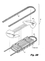
- stator core 12 is shown in an exploded configuration. As illustrated, stator core 12 has a planar shape. This is for illustrative purposes only for purpose of showing the assembly of stator core 12. As will be appreciated, stator core 12 has an arcuate shape.
- First and second phase separators 100 and 101 are installed during manufacture of stator core 12.
- First phase winding 32 seats within longitudinally extending gaps between adjacent stator teeth of the stator core.
- First phase separator 100 then seats in stator core 12 over first phase winding 32 such that it physically contacts first phase winding 32.
- Second phase winding 34 seats thereafter seats over first phase separator such that it is electrically isolated from first phase winding 32.
- successive phase windings and phase separators are installed staggered between teeth as suited for the electrical machine, thereby forming the arrangement shown in Fig. 1 (Fig. 2A showing stator 10 during the assembly process).
- first and second end turn portions 32 and 34 are bound with lacing cord 4 (shown in Fig. 4 ).
- Lacing cord 4 provides structural support to the winding end turns, keeping them in position during assembly and operation of the electrical machine incorporating stator core 12. Lacing cord 4 can also prevent first and second phase windings 32 and 34 from interfering with other components of the electrical machine, and can properly place phase windings 32 and 34 in contact with thermally sensitive elements used for machine overheating protection.
- phase separator insulation can lift up and move out of position due to manipulation of the end turns during the operation.
- the insulation paper moves out of position, it leaves the electrical machine vulnerable in location where the insulation paper has moved out of position because the windings from different phases are in closer proximity to one another.
- lap wound stators include phase windings inserted in a lapping pattern.
- Lap wound stators include portions from more than one phase winding successively positioned within a common stator gap. Since the phase windings are in close proximity to one another, lap wound stators are susceptible to phase-to-phase shorts, e.g. adjacent phases contacting one another. The phase windings therefore require isolation, e.g. adequate dielectric protection, between the adjacent phase windings both in the stator gaps and the phase winding end turns at respective ends of stator core 12.
- First phase separator 100 is shown.
- First phase separator 100 is pre-cut in a specific shape that lends itself to lap winding that simplifies installation and prevents out of position movement of the phase winding during the lacing operation that typically follows winding.
- First phase separator 100 includes a first end portion 120, a second end portion 140, and a midsection 160.
- Midsection 160 connects first end portion 120 to second end portion 140 such that first end portion 120 is arranged on an axially opposite end from second end portion 140.
- First phase separator 100 is constructed from an electrically insulating material, such as dielectric paper or film.
- first phase separator 100 can be constructed from other electrically insulating materials as suitable for a given application.
- stator core 12 can include any number of phase separators as suitable for a given electrical machine design.
- Midsection 160 is configured for fixing first phase separator 100 in an electrical machine including stator 10 for separating adjacent phase windings 14 and 16 from one another.
- First and second end portions 120 and 140 include a separator body having opposing surfaces 102 and 104 for separating end turns of adjacent phase windings of an electrical machine.
- Midsection 160 defines a first longitudinally extending slot 162 with opposed longitudinal edges 164 and 166. Longitudinal edges 164 and 166 correspond to the stator teeth of stator core 12, and have substantially the same axial length as stator tooth 20, 22, and 24 of stator core 12.
- Slot 162 has opposed first and second arcuate edges 168 and 170 that correspond to the axial edges of the stator teeth of stator core 12.
- Arcuate edges 168 and 170 are formed with an arcuate planar shape such that when bowed to conform with the circumference of stator core 12 first and second arcuate edges 168 and 170 conform to planar surfaces of axial end portions 26.
- slot 162 is a first slot and midsection 160 defines a second slot 172.
- Second slot 172 is similar in construction to first slot 162, and includes first and second longitudinal edges 174 and 176 and first and second arcuate edges 178 and 180. Edges 174, 176, 178, and 180 also correspond to longitudinal and axial surfaces of the stator tooth of the electrical machine.
- the slot is a first slot and that the midsection defines a second slot for fixing the phase separator in stator gaps defined by an adjacent stator tooth.
- Midsection 160 includes a plurality of legs connecting first and second end portions 120 and 140 to one another.
- first phase separator 100 includes a first leg 175, a second leg 177 and a third leg 179.
- Second leg 177 is disposed between first and third legs 175 and 179, second leg 177 being adjacent and on one side of first leg 175 and second leg 177 being adjacent and on one side of third leg 179.
- First, second, and third legs 175, 177, and 179 have widths suitable to seat the respective leg between circumferentially adjacent stator teeth within the gaps (slots) of which the legs are installed in-between two different phase windings within the gaps (slots) of stator core 12, thereby fixing the phase separator in stator core 12.
- phase separator 100 can include one leg, two legs, or four or more legs as is suitable for a given application.
- Midsection 160 defines a longitudinal axis 173 that evenly divides midsection 160 into two even sections.
- First and second end portions 120 and 140 are asymmetric with respect to axis 173.
- respective end turns 32, 34, and 36 of phase windings 14, 16, and 18 loop back into stator core 12 in stator gaps separated by at least two intervening stator teeth.
- Asymmetrically forming end portions 120 and 140 provides a phase separator that accommodates such phase winding spacing.
- the asymmetric shape of phase separator is a function of the end turn radius of the winding end turns, which is an artifact of the design of the specific electrical machine.
- first phase separator 100 is as suitable for a given application of first phase separator 100.
- at least one of the first and second end portions 120 and 140 has a crescent shape, thereby spanning multiple stator teeth and bowing about a portion of the circumference of stator core 12.
- First end portion 120 includes an outwardly facing arcuate edge segment 122, a first inward facing edge 124, an inward facing arcuate edge 126, and a second inward facing edge 128.
- First inward facing edge 124 is adjacent to and extends laterally from first leg 175, and is configured for engaging an axial surface of an end portion of a tooth of stator core 12.
- Inward facing arcuate edge 126 is adjacent to and extends laterally from third leg 179, and is configured with a contour to complement the coil shape and to receive lacing cord for securing phase winding end turns.
- Second inward facing edge 128 extends from an end of inward facing arcuate edge 126 opposite third leg 179, and is configured for engaging an axial surface on an end portion of a tooth of stator core 12.
- Second end portion 140 is similar in construction to first end portion 120, and in embodiments axial fixes first phase separator 100 in stator core 12 between opposing inward facing edges of first and second end portions and contacting respective end surfaces of stator core 12.
- Inward facing arcuate edge 126 can prevent the phase separator from bunching up during the lacing operation, and in embodiments can include notches or slits to seat about the cord during the operation.
- First, second and third support legs 175, 177 and 179 provide an additional layer of electrical insulation within the respective gaps (slots) into which they seat, thereby contributing additional dielectric and physical separation to adjacent phases within a given gap (slot).
- First, second and third support legs 175, 177 and 179 of phase separator 100 also provide mechanical stabilization of coil separators 50 within the gaps (slots), thereby preventing them from moving or twisting out position, such as during installation of lacing cord within respective end turns of stator core 12.
Landscapes
- Engineering & Computer Science (AREA)
- Power Engineering (AREA)
- Insulation, Fastening Of Motor, Generator Windings (AREA)
Applications Claiming Priority (2)
| Application Number | Priority Date | Filing Date | Title |
|---|---|---|---|
| US201361886405P | 2013-10-03 | 2013-10-03 | |
| US14/184,036 US9369020B2 (en) | 2012-12-21 | 2014-02-19 | Phase separators for electrical machines |
Publications (3)
| Publication Number | Publication Date |
|---|---|
| EP2858216A2 true EP2858216A2 (de) | 2015-04-08 |
| EP2858216A3 EP2858216A3 (de) | 2016-07-27 |
| EP2858216B1 EP2858216B1 (de) | 2021-02-17 |
Family
ID=51494201
Family Applications (1)
| Application Number | Title | Priority Date | Filing Date |
|---|---|---|---|
| EP14184269.0A Active EP2858216B1 (de) | 2013-10-03 | 2014-09-10 | Isolierende Phasenseparatoren für elektrische Maschinen |
Country Status (1)
| Country | Link |
|---|---|
| EP (1) | EP2858216B1 (de) |
Family Cites Families (6)
| Publication number | Priority date | Publication date | Assignee | Title |
|---|---|---|---|---|
| DE947916C (de) * | 1951-12-13 | 1956-08-23 | Siemens Ag | Isolierende Zwischenlage zur Trennung von Spulen bei insbesondere ruhenden Wicklungen elektrischer Maschinen |
| DE2255345C3 (de) * | 1972-11-11 | 1979-04-19 | Danfoss A/S, Nordborg (Daenemark) | Verfahren zum Einziehen der Statorwicklung einer elektrischen Maschine und Vorrichtung zur Durchführung des Verfahrens |
| US3909648A (en) * | 1973-07-27 | 1975-09-30 | Smith Corp A O | Electric motor having a winding insulating barrier and method of construction |
| IT1129872B (it) * | 1980-11-19 | 1986-06-11 | Aspera Spa | Elemento isolante per avvolgimenti di motori elettrici e motore dotato di tali elementi |
| JPH05336713A (ja) * | 1992-06-03 | 1993-12-17 | Odawara Eng:Kk | 相間絶縁紙の挿入方法及びその装置 |
| US6043584A (en) * | 1998-04-22 | 2000-03-28 | Reliance Electric Industrial Company | End turn phase insulator and method of using same |
-
2014
- 2014-09-10 EP EP14184269.0A patent/EP2858216B1/de active Active
Non-Patent Citations (1)
| Title |
|---|
| None |
Also Published As
| Publication number | Publication date |
|---|---|
| EP2858216A3 (de) | 2016-07-27 |
| EP2858216B1 (de) | 2021-02-17 |
Similar Documents
| Publication | Publication Date | Title |
|---|---|---|
| US9369020B2 (en) | Phase separators for electrical machines | |
| US11469630B2 (en) | Common lamination component for accommodating multiple conductor geometries in an electric machine | |
| CN109155561B (zh) | 旋转电机的定子 | |
| US9590457B2 (en) | Stator of a rotary electric machine | |
| GB2518049A (en) | Electric machine with a slot liner | |
| BR112017021933B1 (pt) | Máquina dinamoelétrica rotativa, gerador de energia eólica, e, instalação de energia eólica | |
| WO2016189192A1 (en) | A winding of an electric machine | |
| US20200328645A1 (en) | Electric machine element and an electric machine | |
| KR101815794B1 (ko) | 전기 기계를 위한 절연 구성 및 조립 방법 | |
| JP5518129B2 (ja) | 回転電機及び回転電機の固定子 | |
| EP4024673B1 (de) | Keil für läuferfeldspulen und läufer mit einem solchen keil | |
| US9859776B2 (en) | Starting current reduction in induction motors | |
| US9882445B2 (en) | Phase separators for electric machines | |
| KR20210064110A (ko) | 회전 전기 기계용 고정자 | |
| EP2858216B1 (de) | Isolierende Phasenseparatoren für elektrische Maschinen | |
| EP3025416B1 (de) | Separator zum trennen von wicklungen | |
| CN113039707A (zh) | 定子绕组装置 | |
| US9124158B2 (en) | Phase separator insulator for electric machine stator | |
| US3719844A (en) | Dynamo-electric machines | |
| EP3869674B1 (de) | Drehende elektrische maschine | |
| US20140306571A1 (en) | Pole separator insert for electric machine stator | |
| WO2015003738A1 (en) | Rotary electrical machine stator core lamination and method of manufacturing thereof | |
| JP2023163418A (ja) | 回転電機 | |
| CN120345158A (zh) | 马达 | |
| JP2023160132A5 (de) |
Legal Events
| Date | Code | Title | Description |
|---|---|---|---|
| PUAI | Public reference made under article 153(3) epc to a published international application that has entered the european phase |
Free format text: ORIGINAL CODE: 0009012 |
|
| 17P | Request for examination filed |
Effective date: 20140910 |
|
| AK | Designated contracting states |
Kind code of ref document: A2 Designated state(s): AL AT BE BG CH CY CZ DE DK EE ES FI FR GB GR HR HU IE IS IT LI LT LU LV MC MK MT NL NO PL PT RO RS SE SI SK SM TR |
|
| AX | Request for extension of the european patent |
Extension state: BA ME |
|
| PUAL | Search report despatched |
Free format text: ORIGINAL CODE: 0009013 |
|
| AK | Designated contracting states |
Kind code of ref document: A3 Designated state(s): AL AT BE BG CH CY CZ DE DK EE ES FI FR GB GR HR HU IE IS IT LI LT LU LV MC MK MT NL NO PL PT RO RS SE SI SK SM TR |
|
| AX | Request for extension of the european patent |
Extension state: BA ME |
|
| RIC1 | Information provided on ipc code assigned before grant |
Ipc: H02K 3/34 20060101AFI20160622BHEP |
|
| STAA | Information on the status of an ep patent application or granted ep patent |
Free format text: STATUS: REQUEST FOR EXAMINATION WAS MADE |
|
| R17P | Request for examination filed (corrected) |
Effective date: 20170127 |
|
| RBV | Designated contracting states (corrected) |
Designated state(s): AL AT BE BG CH CY CZ DE DK EE ES FI FR GB GR HR HU IE IS IT LI LT LU LV MC MK MT NL NO PL PT RO RS SE SI SK SM TR |
|
| STAA | Information on the status of an ep patent application or granted ep patent |
Free format text: STATUS: EXAMINATION IS IN PROGRESS |
|
| 17Q | First examination report despatched |
Effective date: 20190709 |
|
| GRAP | Despatch of communication of intention to grant a patent |
Free format text: ORIGINAL CODE: EPIDOSNIGR1 |
|
| STAA | Information on the status of an ep patent application or granted ep patent |
Free format text: STATUS: GRANT OF PATENT IS INTENDED |
|
| INTG | Intention to grant announced |
Effective date: 20200914 |
|
| GRAS | Grant fee paid |
Free format text: ORIGINAL CODE: EPIDOSNIGR3 |
|
| GRAA | (expected) grant |
Free format text: ORIGINAL CODE: 0009210 |
|
| STAA | Information on the status of an ep patent application or granted ep patent |
Free format text: STATUS: THE PATENT HAS BEEN GRANTED |
|
| AK | Designated contracting states |
Kind code of ref document: B1 Designated state(s): AL AT BE BG CH CY CZ DE DK EE ES FI FR GB GR HR HU IE IS IT LI LT LU LV MC MK MT NL NO PL PT RO RS SE SI SK SM TR |
|
| REG | Reference to a national code |
Ref country code: GB Ref legal event code: FG4D |
|
| REG | Reference to a national code |
Ref country code: CH Ref legal event code: EP |
|
| REG | Reference to a national code |
Ref country code: DE Ref legal event code: R096 Ref document number: 602014074779 Country of ref document: DE |
|
| REG | Reference to a national code |
Ref country code: AT Ref legal event code: REF Ref document number: 1362775 Country of ref document: AT Kind code of ref document: T Effective date: 20210315 |
|
| REG | Reference to a national code |
Ref country code: IE Ref legal event code: FG4D |
|
| REG | Reference to a national code |
Ref country code: LT Ref legal event code: MG9D |
|
| REG | Reference to a national code |
Ref country code: NL Ref legal event code: MP Effective date: 20210217 |
|
| PG25 | Lapsed in a contracting state [announced via postgrant information from national office to epo] |
Ref country code: FI Free format text: LAPSE BECAUSE OF FAILURE TO SUBMIT A TRANSLATION OF THE DESCRIPTION OR TO PAY THE FEE WITHIN THE PRESCRIBED TIME-LIMIT Effective date: 20210217 Ref country code: GR Free format text: LAPSE BECAUSE OF FAILURE TO SUBMIT A TRANSLATION OF THE DESCRIPTION OR TO PAY THE FEE WITHIN THE PRESCRIBED TIME-LIMIT Effective date: 20210518 Ref country code: HR Free format text: LAPSE BECAUSE OF FAILURE TO SUBMIT A TRANSLATION OF THE DESCRIPTION OR TO PAY THE FEE WITHIN THE PRESCRIBED TIME-LIMIT Effective date: 20210217 Ref country code: PT Free format text: LAPSE BECAUSE OF FAILURE TO SUBMIT A TRANSLATION OF THE DESCRIPTION OR TO PAY THE FEE WITHIN THE PRESCRIBED TIME-LIMIT Effective date: 20210617 Ref country code: LT Free format text: LAPSE BECAUSE OF FAILURE TO SUBMIT A TRANSLATION OF THE DESCRIPTION OR TO PAY THE FEE WITHIN THE PRESCRIBED TIME-LIMIT Effective date: 20210217 Ref country code: NO Free format text: LAPSE BECAUSE OF FAILURE TO SUBMIT A TRANSLATION OF THE DESCRIPTION OR TO PAY THE FEE WITHIN THE PRESCRIBED TIME-LIMIT Effective date: 20210517 Ref country code: BG Free format text: LAPSE BECAUSE OF FAILURE TO SUBMIT A TRANSLATION OF THE DESCRIPTION OR TO PAY THE FEE WITHIN THE PRESCRIBED TIME-LIMIT Effective date: 20210517 |
|
| REG | Reference to a national code |
Ref country code: AT Ref legal event code: MK05 Ref document number: 1362775 Country of ref document: AT Kind code of ref document: T Effective date: 20210217 |
|
| PG25 | Lapsed in a contracting state [announced via postgrant information from national office to epo] |
Ref country code: SE Free format text: LAPSE BECAUSE OF FAILURE TO SUBMIT A TRANSLATION OF THE DESCRIPTION OR TO PAY THE FEE WITHIN THE PRESCRIBED TIME-LIMIT Effective date: 20210217 Ref country code: PL Free format text: LAPSE BECAUSE OF FAILURE TO SUBMIT A TRANSLATION OF THE DESCRIPTION OR TO PAY THE FEE WITHIN THE PRESCRIBED TIME-LIMIT Effective date: 20210217 Ref country code: LV Free format text: LAPSE BECAUSE OF FAILURE TO SUBMIT A TRANSLATION OF THE DESCRIPTION OR TO PAY THE FEE WITHIN THE PRESCRIBED TIME-LIMIT Effective date: 20210217 Ref country code: RS Free format text: LAPSE BECAUSE OF FAILURE TO SUBMIT A TRANSLATION OF THE DESCRIPTION OR TO PAY THE FEE WITHIN THE PRESCRIBED TIME-LIMIT Effective date: 20210217 Ref country code: NL Free format text: LAPSE BECAUSE OF FAILURE TO SUBMIT A TRANSLATION OF THE DESCRIPTION OR TO PAY THE FEE WITHIN THE PRESCRIBED TIME-LIMIT Effective date: 20210217 |
|
| PG25 | Lapsed in a contracting state [announced via postgrant information from national office to epo] |
Ref country code: IS Free format text: LAPSE BECAUSE OF FAILURE TO SUBMIT A TRANSLATION OF THE DESCRIPTION OR TO PAY THE FEE WITHIN THE PRESCRIBED TIME-LIMIT Effective date: 20210617 |
|
| PG25 | Lapsed in a contracting state [announced via postgrant information from national office to epo] |
Ref country code: CZ Free format text: LAPSE BECAUSE OF FAILURE TO SUBMIT A TRANSLATION OF THE DESCRIPTION OR TO PAY THE FEE WITHIN THE PRESCRIBED TIME-LIMIT Effective date: 20210217 Ref country code: EE Free format text: LAPSE BECAUSE OF FAILURE TO SUBMIT A TRANSLATION OF THE DESCRIPTION OR TO PAY THE FEE WITHIN THE PRESCRIBED TIME-LIMIT Effective date: 20210217 Ref country code: AT Free format text: LAPSE BECAUSE OF FAILURE TO SUBMIT A TRANSLATION OF THE DESCRIPTION OR TO PAY THE FEE WITHIN THE PRESCRIBED TIME-LIMIT Effective date: 20210217 Ref country code: SM Free format text: LAPSE BECAUSE OF FAILURE TO SUBMIT A TRANSLATION OF THE DESCRIPTION OR TO PAY THE FEE WITHIN THE PRESCRIBED TIME-LIMIT Effective date: 20210217 |
|
| REG | Reference to a national code |
Ref country code: DE Ref legal event code: R097 Ref document number: 602014074779 Country of ref document: DE |
|
| PG25 | Lapsed in a contracting state [announced via postgrant information from national office to epo] |
Ref country code: ES Free format text: LAPSE BECAUSE OF FAILURE TO SUBMIT A TRANSLATION OF THE DESCRIPTION OR TO PAY THE FEE WITHIN THE PRESCRIBED TIME-LIMIT Effective date: 20210217 Ref country code: DK Free format text: LAPSE BECAUSE OF FAILURE TO SUBMIT A TRANSLATION OF THE DESCRIPTION OR TO PAY THE FEE WITHIN THE PRESCRIBED TIME-LIMIT Effective date: 20210217 Ref country code: RO Free format text: LAPSE BECAUSE OF FAILURE TO SUBMIT A TRANSLATION OF THE DESCRIPTION OR TO PAY THE FEE WITHIN THE PRESCRIBED TIME-LIMIT Effective date: 20210217 Ref country code: SK Free format text: LAPSE BECAUSE OF FAILURE TO SUBMIT A TRANSLATION OF THE DESCRIPTION OR TO PAY THE FEE WITHIN THE PRESCRIBED TIME-LIMIT Effective date: 20210217 |
|
| PLBE | No opposition filed within time limit |
Free format text: ORIGINAL CODE: 0009261 |
|
| STAA | Information on the status of an ep patent application or granted ep patent |
Free format text: STATUS: NO OPPOSITION FILED WITHIN TIME LIMIT |
|
| 26N | No opposition filed |
Effective date: 20211118 |
|
| PG25 | Lapsed in a contracting state [announced via postgrant information from national office to epo] |
Ref country code: AL Free format text: LAPSE BECAUSE OF FAILURE TO SUBMIT A TRANSLATION OF THE DESCRIPTION OR TO PAY THE FEE WITHIN THE PRESCRIBED TIME-LIMIT Effective date: 20210217 |
|
| PG25 | Lapsed in a contracting state [announced via postgrant information from national office to epo] |
Ref country code: SI Free format text: LAPSE BECAUSE OF FAILURE TO SUBMIT A TRANSLATION OF THE DESCRIPTION OR TO PAY THE FEE WITHIN THE PRESCRIBED TIME-LIMIT Effective date: 20210217 |
|
| PG25 | Lapsed in a contracting state [announced via postgrant information from national office to epo] |
Ref country code: IT Free format text: LAPSE BECAUSE OF FAILURE TO SUBMIT A TRANSLATION OF THE DESCRIPTION OR TO PAY THE FEE WITHIN THE PRESCRIBED TIME-LIMIT Effective date: 20210217 |
|
| REG | Reference to a national code |
Ref country code: CH Ref legal event code: PL |
|
| REG | Reference to a national code |
Ref country code: BE Ref legal event code: MM Effective date: 20210930 |
|
| PG25 | Lapsed in a contracting state [announced via postgrant information from national office to epo] |
Ref country code: IS Free format text: LAPSE BECAUSE OF FAILURE TO SUBMIT A TRANSLATION OF THE DESCRIPTION OR TO PAY THE FEE WITHIN THE PRESCRIBED TIME-LIMIT Effective date: 20210617 Ref country code: MC Free format text: LAPSE BECAUSE OF FAILURE TO SUBMIT A TRANSLATION OF THE DESCRIPTION OR TO PAY THE FEE WITHIN THE PRESCRIBED TIME-LIMIT Effective date: 20210217 |
|
| PG25 | Lapsed in a contracting state [announced via postgrant information from national office to epo] |
Ref country code: LU Free format text: LAPSE BECAUSE OF NON-PAYMENT OF DUE FEES Effective date: 20210910 Ref country code: IE Free format text: LAPSE BECAUSE OF NON-PAYMENT OF DUE FEES Effective date: 20210910 Ref country code: BE Free format text: LAPSE BECAUSE OF NON-PAYMENT OF DUE FEES Effective date: 20210930 |
|
| PG25 | Lapsed in a contracting state [announced via postgrant information from national office to epo] |
Ref country code: LI Free format text: LAPSE BECAUSE OF NON-PAYMENT OF DUE FEES Effective date: 20210930 Ref country code: CH Free format text: LAPSE BECAUSE OF NON-PAYMENT OF DUE FEES Effective date: 20210930 |
|
| PG25 | Lapsed in a contracting state [announced via postgrant information from national office to epo] |
Ref country code: HU Free format text: LAPSE BECAUSE OF FAILURE TO SUBMIT A TRANSLATION OF THE DESCRIPTION OR TO PAY THE FEE WITHIN THE PRESCRIBED TIME-LIMIT; INVALID AB INITIO Effective date: 20140910 |
|
| P01 | Opt-out of the competence of the unified patent court (upc) registered |
Effective date: 20230522 |
|
| PG25 | Lapsed in a contracting state [announced via postgrant information from national office to epo] |
Ref country code: CY Free format text: LAPSE BECAUSE OF FAILURE TO SUBMIT A TRANSLATION OF THE DESCRIPTION OR TO PAY THE FEE WITHIN THE PRESCRIBED TIME-LIMIT Effective date: 20210217 |
|
| PG25 | Lapsed in a contracting state [announced via postgrant information from national office to epo] |
Ref country code: MK Free format text: LAPSE BECAUSE OF FAILURE TO SUBMIT A TRANSLATION OF THE DESCRIPTION OR TO PAY THE FEE WITHIN THE PRESCRIBED TIME-LIMIT Effective date: 20210217 |
|
| PG25 | Lapsed in a contracting state [announced via postgrant information from national office to epo] |
Ref country code: MT Free format text: LAPSE BECAUSE OF FAILURE TO SUBMIT A TRANSLATION OF THE DESCRIPTION OR TO PAY THE FEE WITHIN THE PRESCRIBED TIME-LIMIT Effective date: 20210217 |
|
| PGFP | Annual fee paid to national office [announced via postgrant information from national office to epo] |
Ref country code: DE Payment date: 20250820 Year of fee payment: 12 |
|
| PGFP | Annual fee paid to national office [announced via postgrant information from national office to epo] |
Ref country code: GB Payment date: 20250820 Year of fee payment: 12 |
|
| PGFP | Annual fee paid to national office [announced via postgrant information from national office to epo] |
Ref country code: FR Payment date: 20250820 Year of fee payment: 12 |
|
| PG25 | Lapsed in a contracting state [announced via postgrant information from national office to epo] |
Ref country code: TR Free format text: LAPSE BECAUSE OF FAILURE TO SUBMIT A TRANSLATION OF THE DESCRIPTION OR TO PAY THE FEE WITHIN THE PRESCRIBED TIME-LIMIT Effective date: 20210217 |