EP2858196A1 - System, method, and program for conserving energy - Google Patents
System, method, and program for conserving energy Download PDFInfo
- Publication number
- EP2858196A1 EP2858196A1 EP12877807.3A EP12877807A EP2858196A1 EP 2858196 A1 EP2858196 A1 EP 2858196A1 EP 12877807 A EP12877807 A EP 12877807A EP 2858196 A1 EP2858196 A1 EP 2858196A1
- Authority
- EP
- European Patent Office
- Prior art keywords
- electrical power
- energy saving
- power consumption
- control
- target demand
- Prior art date
- Legal status (The legal status is an assumption and is not a legal conclusion. Google has not performed a legal analysis and makes no representation as to the accuracy of the status listed.)
- Granted
Links
- 238000000034 method Methods 0.000 title claims description 36
- 230000001419 dependent effect Effects 0.000 claims description 10
- 238000012545 processing Methods 0.000 description 104
- 238000010586 diagram Methods 0.000 description 52
- 230000000694 effects Effects 0.000 description 17
- 230000008569 process Effects 0.000 description 16
- 238000004891 communication Methods 0.000 description 9
- 230000005611 electricity Effects 0.000 description 8
- 208000003443 Unconsciousness Diseases 0.000 description 7
- 230000006870 function Effects 0.000 description 7
- 238000005259 measurement Methods 0.000 description 5
- 230000005540 biological transmission Effects 0.000 description 3
- 230000004044 response Effects 0.000 description 3
- 230000008859 change Effects 0.000 description 2
- 238000013461 design Methods 0.000 description 2
- 238000001514 detection method Methods 0.000 description 2
- 230000006872 improvement Effects 0.000 description 2
- 230000002093 peripheral effect Effects 0.000 description 2
- GRHBODILPPXVKN-UHFFFAOYSA-N 2-[2-(3-butoxyphenyl)ethylamino]-n,n-dimethylacetamide Chemical compound CCCCOC1=CC=CC(CCNCC(=O)N(C)C)=C1 GRHBODILPPXVKN-UHFFFAOYSA-N 0.000 description 1
- 230000002411 adverse Effects 0.000 description 1
- 238000004378 air conditioning Methods 0.000 description 1
- 230000002950 deficient Effects 0.000 description 1
- 230000010365 information processing Effects 0.000 description 1
- 238000005457 optimization Methods 0.000 description 1
- 238000010248 power generation Methods 0.000 description 1
- 238000004321 preservation Methods 0.000 description 1
- 238000007639 printing Methods 0.000 description 1
- 230000009467 reduction Effects 0.000 description 1
- 230000001953 sensory effect Effects 0.000 description 1
- 239000000725 suspension Substances 0.000 description 1
- 230000002747 voluntary effect Effects 0.000 description 1
- XLYOFNOQVPJJNP-UHFFFAOYSA-N water Substances O XLYOFNOQVPJJNP-UHFFFAOYSA-N 0.000 description 1
Images


Classifications
-
- G—PHYSICS
- G05—CONTROLLING; REGULATING
- G05F—SYSTEMS FOR REGULATING ELECTRIC OR MAGNETIC VARIABLES
- G05F1/00—Automatic systems in which deviations of an electric quantity from one or more predetermined values are detected at the output of the system and fed back to a device within the system to restore the detected quantity to its predetermined value or values, i.e. retroactive systems
- G05F1/66—Regulating electric power
-
- H—ELECTRICITY
- H02—GENERATION; CONVERSION OR DISTRIBUTION OF ELECTRIC POWER
- H02J—CIRCUIT ARRANGEMENTS OR SYSTEMS FOR SUPPLYING OR DISTRIBUTING ELECTRIC POWER; SYSTEMS FOR STORING ELECTRIC ENERGY
- H02J3/00—Circuit arrangements for ac mains or ac distribution networks
-
- G—PHYSICS
- G05—CONTROLLING; REGULATING
- G05B—CONTROL OR REGULATING SYSTEMS IN GENERAL; FUNCTIONAL ELEMENTS OF SUCH SYSTEMS; MONITORING OR TESTING ARRANGEMENTS FOR SUCH SYSTEMS OR ELEMENTS
- G05B15/00—Systems controlled by a computer
- G05B15/02—Systems controlled by a computer electric
-
- H—ELECTRICITY
- H02—GENERATION; CONVERSION OR DISTRIBUTION OF ELECTRIC POWER
- H02J—CIRCUIT ARRANGEMENTS OR SYSTEMS FOR SUPPLYING OR DISTRIBUTING ELECTRIC POWER; SYSTEMS FOR STORING ELECTRIC ENERGY
- H02J13/00—Circuit arrangements for providing remote indication of network conditions, e.g. an instantaneous record of the open or closed condition of each circuitbreaker in the network; Circuit arrangements for providing remote control of switching means in a power distribution network, e.g. switching in and out of current consumers by using a pulse code signal carried by the network
-
- H—ELECTRICITY
- H02—GENERATION; CONVERSION OR DISTRIBUTION OF ELECTRIC POWER
- H02J—CIRCUIT ARRANGEMENTS OR SYSTEMS FOR SUPPLYING OR DISTRIBUTING ELECTRIC POWER; SYSTEMS FOR STORING ELECTRIC ENERGY
- H02J3/00—Circuit arrangements for ac mains or ac distribution networks
- H02J3/12—Circuit arrangements for ac mains or ac distribution networks for adjusting voltage in ac networks by changing a characteristic of the network load
- H02J3/14—Circuit arrangements for ac mains or ac distribution networks for adjusting voltage in ac networks by changing a characteristic of the network load by switching loads on to, or off from, network, e.g. progressively balanced loading
-
- H—ELECTRICITY
- H02—GENERATION; CONVERSION OR DISTRIBUTION OF ELECTRIC POWER
- H02J—CIRCUIT ARRANGEMENTS OR SYSTEMS FOR SUPPLYING OR DISTRIBUTING ELECTRIC POWER; SYSTEMS FOR STORING ELECTRIC ENERGY
- H02J2310/00—The network for supplying or distributing electric power characterised by its spatial reach or by the load
- H02J2310/10—The network having a local or delimited stationary reach
- H02J2310/12—The local stationary network supplying a household or a building
- H02J2310/14—The load or loads being home appliances
-
- Y—GENERAL TAGGING OF NEW TECHNOLOGICAL DEVELOPMENTS; GENERAL TAGGING OF CROSS-SECTIONAL TECHNOLOGIES SPANNING OVER SEVERAL SECTIONS OF THE IPC; TECHNICAL SUBJECTS COVERED BY FORMER USPC CROSS-REFERENCE ART COLLECTIONS [XRACs] AND DIGESTS
- Y02—TECHNOLOGIES OR APPLICATIONS FOR MITIGATION OR ADAPTATION AGAINST CLIMATE CHANGE
- Y02B—CLIMATE CHANGE MITIGATION TECHNOLOGIES RELATED TO BUILDINGS, e.g. HOUSING, HOUSE APPLIANCES OR RELATED END-USER APPLICATIONS
- Y02B70/00—Technologies for an efficient end-user side electric power management and consumption
- Y02B70/30—Systems integrating technologies related to power network operation and communication or information technologies for improving the carbon footprint of the management of residential or tertiary loads, i.e. smart grids as climate change mitigation technology in the buildings sector, including also the last stages of power distribution and the control, monitoring or operating management systems at local level
- Y02B70/3225—Demand response systems, e.g. load shedding, peak shaving
-
- Y—GENERAL TAGGING OF NEW TECHNOLOGICAL DEVELOPMENTS; GENERAL TAGGING OF CROSS-SECTIONAL TECHNOLOGIES SPANNING OVER SEVERAL SECTIONS OF THE IPC; TECHNICAL SUBJECTS COVERED BY FORMER USPC CROSS-REFERENCE ART COLLECTIONS [XRACs] AND DIGESTS
- Y02—TECHNOLOGIES OR APPLICATIONS FOR MITIGATION OR ADAPTATION AGAINST CLIMATE CHANGE
- Y02B—CLIMATE CHANGE MITIGATION TECHNOLOGIES RELATED TO BUILDINGS, e.g. HOUSING, HOUSE APPLIANCES OR RELATED END-USER APPLICATIONS
- Y02B90/00—Enabling technologies or technologies with a potential or indirect contribution to GHG emissions mitigation
- Y02B90/20—Smart grids as enabling technology in buildings sector
-
- Y—GENERAL TAGGING OF NEW TECHNOLOGICAL DEVELOPMENTS; GENERAL TAGGING OF CROSS-SECTIONAL TECHNOLOGIES SPANNING OVER SEVERAL SECTIONS OF THE IPC; TECHNICAL SUBJECTS COVERED BY FORMER USPC CROSS-REFERENCE ART COLLECTIONS [XRACs] AND DIGESTS
- Y04—INFORMATION OR COMMUNICATION TECHNOLOGIES HAVING AN IMPACT ON OTHER TECHNOLOGY AREAS
- Y04S—SYSTEMS INTEGRATING TECHNOLOGIES RELATED TO POWER NETWORK OPERATION, COMMUNICATION OR INFORMATION TECHNOLOGIES FOR IMPROVING THE ELECTRICAL POWER GENERATION, TRANSMISSION, DISTRIBUTION, MANAGEMENT OR USAGE, i.e. SMART GRIDS
- Y04S20/00—Management or operation of end-user stationary applications or the last stages of power distribution; Controlling, monitoring or operating thereof
- Y04S20/20—End-user application control systems
- Y04S20/222—Demand response systems, e.g. load shedding, peak shaving
-
- Y—GENERAL TAGGING OF NEW TECHNOLOGICAL DEVELOPMENTS; GENERAL TAGGING OF CROSS-SECTIONAL TECHNOLOGIES SPANNING OVER SEVERAL SECTIONS OF THE IPC; TECHNICAL SUBJECTS COVERED BY FORMER USPC CROSS-REFERENCE ART COLLECTIONS [XRACs] AND DIGESTS
- Y04—INFORMATION OR COMMUNICATION TECHNOLOGIES HAVING AN IMPACT ON OTHER TECHNOLOGY AREAS
- Y04S—SYSTEMS INTEGRATING TECHNOLOGIES RELATED TO POWER NETWORK OPERATION, COMMUNICATION OR INFORMATION TECHNOLOGIES FOR IMPROVING THE ELECTRICAL POWER GENERATION, TRANSMISSION, DISTRIBUTION, MANAGEMENT OR USAGE, i.e. SMART GRIDS
- Y04S20/00—Management or operation of end-user stationary applications or the last stages of power distribution; Controlling, monitoring or operating thereof
- Y04S20/20—End-user application control systems
- Y04S20/242—Home appliances
Abstract
Description
- The present invention relates to an energy saving system, an energy saving method, and an energy saving program.
- Conventionally, energy saving systems for energy saving measures monitor electricity utilization statuses of electric devices, such as lightning systems for air conditioners, at all times and turn off power sources of the electric devices when the electrical power consumption quantity exceeds the predetermined thresholds, thereby allowing restriction of the electrical power consumption quantity. Such energy saving systems have been generally well known. Such saving energy devices are characterized in that controlling takes place automatically and with consideration to users' comfort.
- In
Patent Reference 1, an example of the demand control device controlling the total power usage of a plurality of air conditioning loads is described. Additionally, inPatent Reference 2, an energy saving system that expressly selects a person that should undertake energy saving operations and allows improvement of user awareness regarding saving energy actions is disclosed. - Patent Reference 1: Japanese Published Unexamined Patent Application No.
2006-329468 - Patent Reference 2: Japanese Examined Patent Application Publication No.
4442915 - Operations of nuclear power plants have been suspended in various locations due to the nuclear power plant accident resulting from the Great East Japan Earthquake. The electric power companies must overcome the aforementioned difficulties associated with power supply. However, even amid the tight power supply conditions mentioned above, it is not necessarily essential to undertake strict emergency energy saving measures at all times. It is acceptable simply not to exceed relevant supply capacity during peak hours. In reality, electricity users may often excessively undertake saving energy actions, even in cases in which such actions are not necessary. Excessive saving energy actions cause remarkable inconvenience to actual lives. And often, even in cases in which it is essential to promptly undertake energy saving actions, electricity users may tend to neglect doing so. As such, it is difficult to say that energy saving activities that match the reality of power supply systems have been undertaken.
- In order to solve the aforementioned problems, the present invention proposes an energy saving system comprising an electrical power consumption quantity information acquisition unit for acquiring information on the quantity of electrical power consumed for a plurality of electric devices, a target demand value storage unit for storing a target demand value for electrical power consumption, a supply surplus indicator acquisition unit for acquiring indicators of surplus electric power supplied by an electric power company having control over electrical power within a certain region, and a control unit for controlling the plurality of electric devices based on the acquired supply surplus indicators, the acquired electrical power consumption quantity information, and the stored target demand value.
- According to the present invention having the primary configuration described above, it is possible to encourage electric power users, such as operators, to undertake energy saving actions in order to respond to electric supply surpluses of electric power companies that differ in different seasons, at different hours, etc. As a result, an environment allowing stable electricity supply by electric power companies can be preserved.
-
-
Fig. 1 is a diagram showing an example of functional block diagram of an energy saving system of a first embodiment. -
Fig. 2 is a diagram showing an example of progression of the process for controlling of the energy saving system of the first embodiment. -
Fig. 3 is a schematic diagram showing an example of functional hardware configuration units of the energy saving system of the first embodiment. -
Fig. 4 is a diagram showing an example of progression of the process for controlling of the energy saving system of the first embodiment. -
Fig. 5 is a diagram showing an example of functional block diagram of the energy saving system of a second embodiment. -
Fig. 6 is a diagram showing an example of restriction control undertaken via the energy saving system of the second embodiment. -
Fig. 7 is a diagram showing an example of progression of the process for controlling of the energy saving system of the second embodiment. -
Fig. 8 is a diagram showing an example of functional block diagram of the energy saving system of a third embodiment. -
Fig. 9 is a diagram showing an example of restriction control undertaken via the energy saving system of the third embodiment. -
Fig. 10 is a diagram showing another example of restriction control undertaken via the energy saving system of the third embodiment. -
Fig. 11 is a diagram showing an example of progression of the process for controlling of the energy saving system of the third embodiment. -
Fig. 12 is a diagram showing an example of progression of the process for controlling of the energy saving system of the third embodiment. -
Fig. 13 is a diagram showing an example of functional block diagram of the energy saving system of a fourth embodiment. -
Fig. 14 is a diagram showing an example of database for groups stored in the energy saving system of the fourth embodiment. -
Fig. 15 is a diagram showing an example of progression of the process for controlling of the energy saving system of the fourth embodiment. -
Fig. 16 is a diagram showing an example of functional block diagram of the energy saving system of the energy saving system of a fifth embodiment. -
Fig. 17 is a diagram showing an example of restriction control undertaken via the energy saving system of the energy saving system of the fifth embodiment. -
Fig. 18 is a diagram showing an example of progression of the process for controlling of the energy saving system of the fifth embodiment. -
Fig. 19 is a diagram showing an example of functional block diagram of the energy saving system of a sixth embodiment. -
Fig. 20 is a diagram showing an example of progression of the process for controlling of the energy saving system of the sixth embodiment. - Embodiments of the present invention will be described hereinafter with reference to the drawings. The mutual relationship between the embodiments and claims is described as follows. A first embodiment will mainly describe
Claims 1, 7, and 13. A second embodiment will mainly describeClaims 2, 8, and 13. A third embodiment will mainly describeClaims 3, 9, and 13. A fourth embodiment will mainly describeClaims Claims 6, 12, and 13. The present invention is not limited to the above embodiments and may be embodied in various forms without exceeding the scope thereof. - According to an energy saving system of a first embodiment, target demand values for electrical power consumption of homes, workplaces, facilities, etc. are stored and information on the quantity of electrical power consumed for a plurality of electric devices is acquired. At the same time, indicators of surplus electric power supplied by an electric power company having control over electrical power within a certain region are acquired. For example, the information on current supply quantity compared with the remaining electrical power that can be supplied and remaining supply capacity are acquired. Based on the acquired supply surplus indicators, the acquired electrical power consumption quantity information, and the stored target demand value, the plurality of electric devices of homes, workplaces, facilities, etc. can be controlled. Such configuration allows users of electric devices for which energy saving control takes place to undertake energy saving actions based on the electricity utilization statuses of overall regions of electric power companies as well as on their own. Therefore, it is possible to promote efficiency and optimization for energy saving and electric power saving efforts.
-
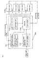
Fig. 1 is a diagram showing an example of functional block diagram of an energy saving system of a first embodiment. As described inFig. 1 , an "energy saving system" (0100) comprises an "electrical power consumption quantity information acquisition unit" (0101), a "target demand value storage unit" (0102), a "supply surplus indicator acquisition unit" (0103), and a "control unit" (0104), and controls an "electric device" (0105) as needed. - Note that, the functional blocks of the integrated interface devices can be implemented by hardware, software, or both hardware and software. Specifically, in the case of using a computer, the respective units are implemented by the hardware configured by a CPU, a main memory, a bus, a secondary storage device (e.g., a hard disk or a nonvolatile memory, a storage media such as CD-ROM or DVD-ROM, or a reading drive for the above media), an input device for an inputting information, a printing device, display device, a sensor, a measuring instrument (e.g., a power meter), a clock, electric power lines, communication lines, other peripheral devices, an interface for such other peripheral devices and communication interface, a driver program for controlling the aforementioned hardware, and other application programs. The CPU executes operation in accordance with the program developed on the main memory, so that processing and storing of the data inputted through the input device, the interface, or the like and stored in the memory or the hardware are carried out, and instructions to control the hardware and software are generated. Moreover, the present invention can be implemented not only as an apparatus but also as a method thereof.
- Moreover, some of the present invention can be configured as software. Furthermore, a software product and a storage medium in which such product is included in a recoding medium fall within the technical scope of the present invention as a matter of course. (The same applies throughout the entire specification.)
- The "electrical power consumption quantity information acquisition unit" retains the function for acquiring information on the quantity of electrical power consumed for a plurality of electric devices. More concretely, for example, the "electrical power consumption quantity information acquisition unit" acquires information on electrical power consumption quantity of a plurality of electric devices measured using a power meter. It is desirable to obtain information on electrical power consumption quantity at predetermined intervals of about 5 to 60 minutes, which are relatively short intervals. (The length of such intervals depends on design.) Moreover, it is acceptable to obtain information on electrical power consumption quantity to be acquired on a piece-by-piece basis, classified by individual electric device, for a plurality of electric devices, or on a collective basis for such plurality as a whole.
- In case that the aforementioned information has been obtained on a collective basis for a plurality of electric devices, a plurality of electric devices would constitute a unit for controlling.
- Moreover, in addition to information on electrical power consumption quantity, a configuration is possible in which information on identification IDs and setting modes for electric devices is also obtained. (Identification IDs will be explained in detail in the section on a fourth embodiment.) Such information can be used as determination data upon selecting electric devices to be restricted via the control unit described below.
- The "target demand value storage unit" retains the function for storing a target demand value as a target value for the quantity of electrical power consumed for a plurality of electric devices. A target demand value can be configured to be changed via an operation input device of the energy saving system, or it can be configured to be changed externally via a wired or wireless communication line. Furthermore, a target demand value can be configured to be established and changed by remote control using a center device other than the energy saving system. Additionally, it is acceptable to establish a target demand value in different ways depending on the time of day (i.e., morning, daytime, or night), depending on intervals (i.e., 30-minute intervals or 1-hour intervals), or the like.
- The "supply surplus indicator acquisition unit" retains the function for acquiring indicators of surplus electric power supplied by an electric power company having control over electrical power within a certain region. The term "supply surplus indicator" refers to a certain indicator that shows the supply surplus of an electric power company. For example, more specifically, such indicator may be computed as follows: The value resulting when the expected maximum electrical power consumption quantity within all regions of an electric power company is divided by the maximum electrical power supply (i.e., the quantity that can be supplied per unit time for the entirety of the regions of the electric power company), and the resultant is deducted from 1.
- In addition, for example, a value of zero for the supply surplus indicator means that the relevant electric power company will no longer provide electric power. If the aforementioned conditions take place, voltage and frequency of the electric power provided by an electric power company begin to decrease and neither normal power generation nor normal power transmission can take place. As a result, the risk of blackout for all relevant regions will increase. That is to say, the higher the supply surplus indicator, the greater the quantity of electric power provided by an electric power company. As a result, consumers are less likely to face the imminent need for energy saving actions. And the lower the supply surplus indicator, the lower the quantity of electric power provided by an electric power company and the risk of blackout for all relevant regions will increase. As a result, consumers are more likely to face the imminent need for energy saving actions. For example, it is said that if a supply surplus indicator falls by approximately 8%, the risk of blackout in a given region will become apparent. In order to avoid the aforementioned situation, there is a great need for individual electric power users to undertake energy saving actions, thereby allowing restriction of the total electrical power consumption quantity within a region, and a substantial need for an electric power company to preserve a stable power supply surplus. In recent years, in order to avoid the risk of blackout, a system for planned power outage has been adopted, but the adverse effect of such system on industries and lives is immeasurable.
- In addition, an electric power company discloses electrical power consumption quantity per unit time (e.g., 5 minutes, 1 hour, or the like), the amount of electric power that can be provided per unit time, and a supply surplus indicator computed based on such amount. The expression "acquiring indicators of surplus electric power" specifically refers to acquisition of a supply surplus indicator disclosed as described above via electric communication lines. A supply surplus indicator may be obtained on an hourly basis, when the result values are disclosed, or it may be obtained at 5-minute intervals, when preliminary figures are disclosed. It is desirable to establish shorter intervals for a supply surplus indicator, so as to allow energy saving activities to be more properly aligned with regional power supply situations. However, giving consideration to actual conditions of electric power usage by users, it is acceptable to establish longer intervals for a supply surplus indicator.
- The times (i.e., intervals) at which a supply surplus indicator is obtained can be configured so that they can be changed via the energy saving system as needed.
- The "control unit" retains the function for controlling the plurality of electric devices based on the acquired supply surplus indicators, the acquired electrical power consumption quantity information, and the stored target demand value. The expression "controlling the plurality of electric devices based on the acquired supply surplus indicators, the acquired electrical power consumption quantity information, and the stored target demand value" used above refers to a case in which controlling takes place with the use of 3 values. However, relevant cases are not limited to those in which all 3 of the aforementioned values are constantly in use.
- More concretely, in a situation in which electric power supply by an electric power company is normal and supply surplus is not in imminent danger, the control unit is used to control electrical power consumption quantity based on a target demand value.
Fig. 2 is a diagram showing an example of progression of the process for controlling of the energy saving system of the first embodiment. - Therein, "z" represents electrical power consumption quantity, "y" represents the target demand value, "z (1 + k)" represents the electrical power consumption quantity that can be expected for the period for which the target demand value has been established, and "A" represents electric power to be restricted during the same period. In case that there is a sufficient surplus of the electrical power consumption quantity in relation to the target demand value, controlling for electric power saving will not be undertaken in the first place. On the other hand, in case that the electrical power consumption quantity is closer to the target demand value, if the risk of exceeding the target demand value becomes high (that is to say, in case that the computer predicts that electrical power consumption quantity during a certain unit time will exceed the target demand value), controlling will be implemented so the target demand value is not exceeded. For example, in case that it has been predicted that consumption will exceed 90% of the target demand value, a method for commencing controlling can be implemented, and the aforementioned percentage can be changed as needed. In addition, "k" is a coefficient determined based on setup environment, (i.e., relevant homes, offices, and workplaces), types of electric devices, weather on a given day, etc., and it is a design value. In any case, the energy saving system of the first embodiment is characterized in that controlling takes place using expected electric power quantity instead of actual electrical power consumption quantity at a given time.
- In case that electric power supply by an electric power company has been impeded, controlling will take place so as to restrict electrical power consumption quantities of electric devices. Preferably, in case that expected electrical power consumption quantity is sufficiently low in relation to a target demand value, there will be less controlling of electric power saving, or no controlling of the same. In case that expected electrical power consumption quantity of electric devices is relatively close to a target demand value, controlling will take place so as to reduce electrical power consumption quantities for electric devices to a relatively greater extent.
- In case that electric power supply by an electric power company has been impeded, a supply surplus indicator at the time at which controlling of electrical power consumption quantities of electric devices via the energy saving system of the first embodiment commences is called a "low supply surplus value." As described above, in general, it is said that in case that a supply surplus indicator falls below 8%, the risk of blackout will become apparent. The aforementioned value can be also changed depending upon the regional electricity supply-demand environment. Thus, a low supply surplus value ranging from 1% to 15% (and, if possible, from about 8% to 12%) can be established in a manner that allows it to be alterable. Such configuration allows users to undertake the energy saving actions that can immediately reflect the electricity supply-demand balance at a corresponding time.
- The expression "controlling the plurality of electric devices" includes a situation in which off control of electric devices takes place. In addition to the method described above, for example, in the case of an electric device that can change electrical power consumption quantity based on the setting mode of such electric device, it is also possible to adopt a method for controlling that allows change of such setting mode. In regard to an electric device that allows restriction of electric power quantity outputted to a certain level, it is also possible to adopt a method for controlling that allows reduction of electrical power consumption quantity. As a specific example, in case that an electric device is a lightning system, such lightning system will be turned off for a predetermined number of hours. Additionally, in case that an electric device is an air conditioner, for example, a method for controlling in which off control of a compressor unit takes place and, during the period of such control, the condition of the corresponding air conditioner is changed to an air supply state without temperature regulation is possible. The aforementioned controls allow an air supply mode for an air conditioner to be established. In summer, room temperature naturally becomes slightly higher. In winter, room temperature naturally becomes slightly lower. Users of an electric device controlled by the energy saving system of the first embodiment can naturally gain a sense of energy saving through sensory awareness of the extent of room brightness, the air volume of an air supply mode, room temperature fluctuation, etc. Therefore, they will be able to recognize the need to undertake energy saving actions on such occasions.
- Furthermore, another method for controlling can be also established so that some rather than all of a plurality of electric devices can be controlled. Adoption of the aforementioned method for controlling requires users to undertake voluntary energy saving actions for uncontrolled electric devices and allows them to enhance their energy saving awareness as a result.
- For example, when off control of all electric devices is established, it is difficult for users to undertake energy saving actions voluntarily. However, in case that there exist other electric devices to be further controlled in addition to controlled electric devices, it is easy for users to undertake energy saving actions prior to controlling such other electric devices. Moreover, it is not required to extend any control lines from the energy saving system for every electric device. Therefore, it is also possible to restrict facility costs.
- Moreover, there are electric devices for which a relatively low amount of electric power is necessary to save by controlling. In relation to the expression "... which a relatively low amount of electric power is necessary to save by controlling," it is possible to imagine a situation in which promotion of electric power saving would cause damage and increase inconvenience to a remarkable extent. Specific examples are factory facilities that make it difficult to resume operations due to suspension of refrigerators, elevators, water service pumps, etc. Additionally, there exist devices for which off control occurs suddenly. Examples of such devices are personal computers used for various types of information processing, and various forms of recording media that require use over a long period of time. Reasons for employing a configuration in which off control does not take place for every electric device include cases in which setup is possible such that not every electronic device is controlled. According to the energy saving system of the first embodiment, controlling takes place via use of a supply surplus indicator that cannot be controlled by users of electric devices. Therefore, in order to avoid a situation in which all electric devices are suddenly controlled at an unexpected time, it is useful to exercise partial control of electric devices.
-
Fig. 3 is a schematic diagram showing an example of functional hardware configuration units of the energy saving system of the first embodiment. Operations for hardware configuration units are explained hereinafter with reference toFig. 3 . - As illustrated in
Fig. 3 , the energy saving system comprises a "CPU" (0301), a "storage unit (storage medium)" (0302), a "main memory" (0303), and an "interface" (0304). Such interface allows transmission and reception of data signal, control signal, etc. relating to electric power consumption with an "Internet communication device" (0305), an "operation input apparatus" (0306), an "electric measuring instrument" (0307), and an "electric device" (0308). The aforementioned configuration is mutually connected by a "system bus" (0309) as a data communication path, and transmission, reception, and processing of information take place. The interface, the electric devices, and an electric measuring instrument are connected via a wired or wireless communication line. As a configuration using a communication line, it is also acceptable to use a form of power line communication (PLC) utilizing power lines. - The CPU loads a program for acquiring information on electrical power consumption quantity, acquires information on electrical power consumption quantities of a plurality of electric devices from the electric measuring instrument via the interface, and stores such information at a predetermined address of the main memory. Acquisition of the information on electrical power consumption quantity can be configured to take place at 1-minute intervals using a clock (omitted in the figure) incorporated in the energy saving system. Moreover, based on the acquired electrical power consumption quantity information, the electrical power consumption quantity expected for a predetermined period specified in the storage unit (for which a target demand value is established) is computed.
- Subsequently, the CPU loads a Program for acquiring supply surplus indicators, acquires a supply surplus indicator disclosed by an electric power company via the interface, and stores such information at the predetermined address of the main memory. Acquisition of a supply surplus indicator can be configured to take place at 5-minute or 1-hour intervals based on a clock (omitted in the figure) incorporated in the energy saving system.
- Next, the CPU loads a control program, stores a low supply surplus value that has been stored in the storage unit beforehand at a predetermined address of the main memory, compares the size of such value with that of the supply surplus indicator, and stores in the processing result at the predetermined address of the main memory. In case that the supply surplus indicator exceeds the low supply surplus value (meaning that the supply surplus is sufficient) based on the measurement result described above, the expected electrical power consumption quantity that has been already stored and the target demand value are compared, and the result thereof is stored at the predetermined address of the main memory. In case that the result shows that the expected electrical power consumption quantity is larger than the target demand value, restriction control for some or all electric power consumption of a plurality of electric devices takes place. In case that the measurement result described above shows that the supply surplus indicator falls below the low supply surplus value (meaning the supply surplus is deficient), restriction control for electrical power consumption quantities of electric devices in a uniform manner and at a certain changeable rate takes place.
-
Fig. 4 is a diagram showing an example of progression of the process for controlling of the energy saving system of the first embodiment. The processing flow ofFig. 4 comprises the following steps. Initially, information on the quantity of electrical power consumed for a plurality of electric devices is obtained (S0401). Indicators of surplus electric power supplied by an electric power company are obtained (S0402). Next, it is determined whether or not the supply surplus indicator falls below the low supply surplus value (S0403). In case that it has been determined that the supply surplus indicator does not fall below the low supply surplus value, the processing moves on to the step 0404. In case that it has been determined that the supply surplus indicator falls below the low supply surplus value, the processing moves on to the step 0405. It is determined whether or not the expected electrical power consumption quantity exceeds the target demand value (S0404). In case that it has been determined that the expected electrical power consumption quantity does not exceed the target demand value, the processing returns to the step 0401. In case that it has been determined that the expected electrical power consumption quantity exceeds the target demand value, the processing moves on to the step 0405. Restriction control for some or all electric power consumption quantity of a plurality of electric devices takes place (S0405). - According to the energy saving system of the first embodiment, users of an electric device controlled by the energy saving system of the first embodiment can attain a sense of energy saving. Such control will influence electric power consumption actions of general users. Therefore, consciousness of the need to undertake energy saving actions in order to prevent situations such as large-scale blackouts in regional units before they take place tends to be improved. As a result, such improvement will possibly contribute to electric power saving throughout all regions controlled by an electric power company.
- The energy saving system of a second embodiment is basically the same as that of the first embodiment. The energy saving system of the second embodiment is characterized in that the lower the value of the supply surplus indicators, the greater the restriction of some or all of the electrical power consumed by the plurality of electric devices.
-
Fig. 5 is a diagram showing an example of functional block diagram of the energy saving system of a second embodiment. As illustrated inFig. 5 , an "energy saving system" (0500) comprises an "electrical power consumption quantity information acquisition unit" (0501), a "target demand value storage unit" (0502), a "supply surplus indicator acquisition unit" (0503), and a "control unit" (0504). The control unit comprises a "first control rule storage means" (0505) for storing a "first control rule." Explanations of the first control rule storage means, which are not included among the explanations of the saving energy system ofFig. 1 of the first embodiment, are explained hereinafter. - The "first control rule storage means" retains the first control rule. The term "first control rule" refers to a control rule under the condition that the lower the value of the supply surplus indicators, the greater the restriction of some or all of the electrical power consumed by the plurality of electric devices. The expression "the lower the value of the supply surplus indicators" specifically refers to a situation in which a regional electricity supply-demand balance is unstable and supply by a corresponding electric power company is impeded. In case that the aforementioned situation continues for a long time, if there is even a slight increase in electrical power consumption quantity, the power supply system will be immediately hindered, and the risk of simultaneous regional blackout will increase. However, adoption of the configuration of the second embodiment allows energy saving actions to be undertaken in response to a situation in which the aforementioned regional power supply is impeded. As a result, it is possible to contribute to the stability of the power supply throughout a region.
- In addition, the expression "the lower the value of the supply surplus indicators, the greater the restriction of some or all of the electrical power consumed by the plurality of electric devices" specifically refers to a situation in which, when supply surplus indicator values are lower than low supply surplus values, gradual restriction control for electrical power consumption will take place to a greater extent.
Fig. 6 is a diagram showing an example of restriction control undertaken via the energy saving system of the second embodiment. In connection with the aforementioned, "x" represents a supply surplus indicator, "s" represents a low supply surplus value, and "A" represents a percentage value for the electric power quantity subject to restriction control (i.e., restriction control percentage value). As depicted inFig. 6 , according to the energy saving system of the second embodiment, the greater the difference value resulting when a supply surplus indicator "x" is deducted from a low supply surplus value "s," (i.e., the more impeded the power supply situation is), the greater the control of the relevant electric power quantities. Some or all of the electrical power consumed by the plurality of electric devices is uniformly controlled at a particular restriction rate. Subsequently, when a supply surplus indicator "x" exceeds a low supply surplus value "s," (i.e., when the power supply situation become relatively stable), controlling stops. - The electric power quantities for which restriction control takes place are subject to a method based on a specific restriction percentage value (10%, 15%, 20%, or the like) as depicted in
Fig. 6 . In addition to such method, it is acceptable to establish electric power quantities for which restriction control takes place via a method that more accurately reflects the actual power supply situation. A restriction percentage value can be obtained as follows. For example, the value resulting when a supply surplus indicator "x" is deducted from a low supply surplus value "s" is multiplied by a certain coefficient, and the resultant is the restriction percentage value. As described above, a restriction percentage value can be changed as needed. Such value is established in order to sufficiently preserve supply surplus of an electric power company. Therefore, such value would be sufficient to the extent that it allows supply surplus for an electric power company to be sufficiently preserved. The maximum value can be set at about 50%. (The same applies to other embodiments in which controlling takes place using a supply surplus indicator.) - A hardware configuration of the energy saving system of the second embodiment is basically the same as that of the energy saving system of the first embodiment explained with reference to
Fig. 2 . - The CPU loads a control program, stores a low supply surplus value that has been stored in the storage unit beforehand at a predetermined address of the main memory, compares the size of such value with that of the supply surplus indicator, and stores in the processing result at the predetermined address of the main memory. In case that the supply surplus indicator falls below the low supply surplus value based on the measurement result described above, the processing for computation of the difference between the values is executed. The result thereof is stored at the predetermined address of the main memory. The first control rule is loaded, the processing for determining the restriction quantity corresponding to the computation processing result described above is executed, and restriction control for some or all electric power consumption of a plurality of electric devices takes place.
-
Fig. 7 is a diagram showing an example of progression of the process for controlling of the energy saving system of the second embodiment. The processing flow ofFig. 7 comprises the following steps. Initially, information on the quantity of electrical power consumed for a plurality of electric devices is obtained (S0701). Indicators of surplus electric power supplied by an electric power company are obtained (S0702). Next, it is determined whether or not the supply surplus indicator falls below the low supply surplus value (S0703). In case that it has been determined that the supply surplus indicator does not fall below the low supply surplus value, the processing moves on to the step 0704. In case that it has been determined that the supply surplus indicator falls below the low supply surplus value, the processing moves on to the step 0705. It is determined whether or not the expected electrical power consumption quantity exceeds the target demand value (S0704). In case that it has been determined that the expected electrical power consumption quantity does not exceed the target demand value, the processing returns to the step 0701. In case that it has been determined that the expected electrical power consumption quantity exceeds the target demand value, the processing moves on to the step 0707. The difference between the supply surplus indicator and the low supply surplus value is computed (S0705). - The electric power consumption quantity to be restricted in response to the aforementioned difference value is determined (S0706). Restriction control for some or all electric power consumption of a plurality of electric devices takes place (S0707).
- According to the energy saving system of the second embodiment, energy saving actions will be undertaken based on the electric power quantity that can be provided by an electric power company, and such actions can be changed at any time depending upon various factors, such as users' unique electric power consumption conditions as well as weather conditions and operational situations of power plants. Therefore, it is possible to undertake energy saving actions more appropriately in line with the actual conditions of usage compared with the effects of the first embodiment, thereby contributing to preservation of a stable regional electric power supply environment.
- The energy saving system of a third embodiment is basically the same as that explained in the first embodiment. In the case of controlling of a plurality of electric devices, it is possible that the closer the expected electrical power consumption quantity is to 100% of the stored target demand value, the greater the restriction of some or all of the electrical power consumed by the plurality of electric devices when controlling is performed so as to restrict some or all of the electrical power consumed by the plurality of electric devices. Adoption of such configuration allows control of electric devices based on the degree of achievement of users' goals for energy saving, even in cases in which the power supply is impeded. Thus, it is possible to encourage users to undertake energy saving actions so that they can achieve their own energy saving goals on a regular basis so as not to experience the impact of the aforementioned control to the utmost extent possible.
-
Fig. 8 is a diagram showing an example of functional block diagram of the energy saving system of a third embodiment. As illustrated inFig. 8 , an "energy saving system" (0800) comprises an "electrical power consumption quantity information acquisition unit" (0801), a "target demand value storage unit" (0802), a "supply surplus indicator acquisition unit" (0803), and a "control unit" (0804). The control unit comprises a "second control rule storage means" (0805) for storing a "second control rule." Explanations of the second control rule storage means, which are not included among the explanations of the saving energy system ofFig. 1 of the first embodiment, are explained hereinafter. - The "second control rule storage means" retains the second control rule. The term "second control rule" refers to a control rule under the condition that the closer the expected electrical power consumption quantity is to 100% of the stored target demand value, the greater the restriction of some or all of the electrical power consumed by the plurality of electric devices. The term "the percentage of the stored target demand value accounted for by the expected electrical power consumption quantity" specifically refers to the percentage value representing how much electric power quantity is expected to be consumed in relation to the target demand value. Such value is so called a target achievement rate. The smaller such value, the lower the electrical power consumption quantity in relation to the target demand value. In such a case, energy saving is being performed on a daily basis. The larger such value, the greater the energy saving actions that are necessary.
-
Fig. 9 is a diagram showing an example of restriction control undertaken via the energy saving system of the third embodiment. In connection with the aforementioned, "x" represents a supply surplus indicator, "s" represents a low supply surplus value, "z" represents an electrical power consumption quantity, "y" represents a target demand value, "z (1 + k)" represents the electrical power consumption quantity expected during a period for which a target demand value is established, and "A" represents a percentage value for the electric power quantity subject to restriction control. As described above, when using electric devices for which target achievement rates are high, there are many controllable electrical power consumption quantities. Moreover, there is a great need to encourage users who consume large amounts of electric power to undertake daily energy saving actions. The energy saving system of the third embodiment allows such users to enhance their awareness of energy saving so that they can deliberately undertake energy saving actions on a daily basis. - In addition, the energy saving system of the third embodiment can be configured so that energy saving control can be undertaken in combination with two control rules, which are the first control rule characterized in the energy saving system of the second embodiment and the second control rule. In the case of such configuration, the control unit first computes the expected electrical power consumption quantity as a percentage of the target demand value in accordance with the second control rule, determines the specific scope of electric power quantity to be restricted, and subsequently executes restriction control for electric power consumption of electric devices based on the first control rule.
-
Fig. 10 is a diagram showing another example of restriction control undertaken via the energy saving system of the third embodiment. Therein, "x" represents a supply surplus indicator, "s" represents a low supply surplus value, "y" represents the target demand value, "z (1 + k)" represents the electrical power consumption quantity that can be expected for the period for which the target demand value has been established, and "A" represents a percentage value for the electric power quantity subject to restriction control. As depicted inFig. 10 , as long as the supply surplus indicator exceeds the low supply surplus value, the energy saving system of the third embodiment undertakes controlling depending upon whether or not the electrical power consumption quantity exceeds the target demand value as depicted inFig. 2 . On the other hand, in case that the supply surplus indicator is less than or equal to the low supply surplus value, based on the proximity of the electrical power consumption quantity to the target demand value, the range of electric power percentage is determined. (InFig. 10 , for example, the ranges are 10% through 14%, 14% through 18 %, and 18% through 20%.) Furthermore, based on the extent of the value resulting when the supply surplus indicator is deducted from the low supply surplus value, restriction control for the electrical power consumption quantity takes place within the scope of the aforementioned range of electric power percentage to be restricted. The greater the percentage of the expected electric power consumption quantity in relation to the target demand value is, the greater the extent of the electric power quantity to be reduced. A configuration that focuses on such point allows segmentalization of the patterns for restriction control and flexible restriction control for users undertaking various electric power consumption actions. - A hardware configuration of the energy saving system of the third embodiment is basically the same as that of the energy saving system of the first embodiment or the second embodiment explained with reference to
Fig. 3 . However, the energy saving system of the third embodiment is possible under the condition that the closer the expected electrical power consumption quantity is to 100% of the stored target demand value, the greater the restriction of some or all of the electrical power consumed by the plurality of electric devices. - The CPU loads a control program, stores a low supply surplus value that has been stored in the storage unit beforehand at a predetermined address of the main memory, compares the size of such value with that of the supply surplus indicator, and stores in the processing result at the predetermined address of the main memory. In case that the measurement result described above indicates that the supply surplus indicator falls below the low supply surplus value, the expected electrical power consumption quantity as a percentage of the target demand value is computed. The processing result is stored at the predetermined address of the main memory. The second control rule is loaded, the processing for determining the restriction quantity corresponding to the computation processing result described above is executed, and restriction control for some or all electric power consumption of a plurality of electric devices takes place.
- The specific processing for the control unit in case that the energy saving system of the third embodiment also retains the first control rule storage means is described as follows. In such case, the CPU loads a control program, stores a low supply surplus value that has been stored in the storage unit beforehand at a predetermined address of the main memory, compares the size of such value with that of the supply surplus indicator, and stores in the processing result at the predetermined address of the main memory. In case that the supply surplus indicator falls below the low supply surplus value based on the measurement result described above, the processing for computation of the expected electrical power consumption quantity as a percentage of the target demand value is computed. The result thereof is stored at the predetermined address of the main memory. The second control rule is loaded, the processing for determining the restriction quantity corresponding to the computation processing result described above is executed, and the result thereof is stored at the predetermined address of the main memory. Subsequently, the processing for computation of the difference between the supply surplus indicator and the low supply surplus value is executed, and the result thereof is stored at the predetermined address of the main memory. The first control rule is loaded, the processing for determining the restriction quantity corresponding to the computation processing result described above within the scope of restriction quantity determined as above is executed, and restriction control for some or all electric power consumption of a plurality of electric devices takes place.
-
Fig. 11 is a diagram showing an example of progression of the process for controlling of the energy saving system of the third embodiment. The processing flow ofFig. 11 comprises the following steps. Initially, information on the quantity of electrical power consumed for a plurality of electric devices is obtained (S1101). Indicators of surplus electric power supplied by an electric power company are obtained (S1102). Next, it is determined whether or not the supply surplus indicator falls below the low supply surplus value (S1103). In case that it has been determined that the supply surplus indicator does not fall below the low supply surplus value, the processing moves on to the step 1104. In case that it has been determined that the supply surplus indicator falls below the low supply surplus value, the processing moves on to the step 1105. It is determined whether or not the expected electrical power consumption quantity exceeds the target demand value (S1104). In case that it has been determined that the expected electrical power consumption quantity does not exceed the target demand value, the processing returns to thestep 1101. In case that it has been determined that the expected electrical power consumption quantity exceeds the target demand value, the processing moves on to thestep 1107. The expected electrical power consumption quantity as a percentage of the target demand value is computed (S 1105). - The electric power consumption to be restricted in relation to the aforementioned percentage is determined (S1106). Restriction control for some or all electric power consumption of a plurality of electric devices takes place (S1107).
-
Fig. 12 is a diagram showing an example of progression of the process for controlling of the energy saving system of the third embodiment. The processing flow ofFig. 12 comprises the following steps. Initially, information on the quantity of electrical power consumed for a plurality of electric devices is obtained (S1201). Next, indicators of surplus electric power supplied by an electric power company are obtained (S1202). Subsequently, it is determined whether or not the supply surplus indicator falls below the low supply surplus value (S1203). In case that it has been determined that the supply surplus indicator does not fall below the low supply surplus value, the processing moves on to the step 1204. In case that it has been determined that the supply surplus indicator falls below the low supply surplus value, the processing moves on to the step 1205. It is determined whether or not the expected electrical power consumption quantity exceeds the target demand value (S1204). In case that it has been determined that the expected electrical power consumption quantity does not exceed the target demand value, the processing returns to the step 1201. In case that it has been determined that the expected electrical power consumption quantity exceeds the target demand value, the processing moves on to thestep 1209. The expected electrical power consumption quantity as a percentage of the target demand value is computed (S1205). The range of restriction quantity corresponding to the a percentage value mentioned above is computed (S1206). The difference between the supply surplus indicator and the low supply surplus value is computed (S1207). The electric power consumption quantity to be restricted in response to the aforementioned difference value is determined (S1208). Restriction control for some or all electric power consumption of a plurality of electric devices takes place (S1209). - In addition to the effect of the first embodiment, the energy saving system of the third embodiment makes it possible to connect the controlling pattern used in an emergency in which electric power supply situation is impeded with the extent of target achievement for daily energy saving of users. Thus, the energy saving system of the third embodiment allows users to enhance their energy saving awareness, keeping in mind such connection on a daily basis as well as in the event of emergency.
- The energy saving system of a fourth embodiment is basically the same as that of the first embodiment. The target demand value has been set based on categorization of the plurality of electric devices into a plurality of groups, and control of the electrical power to be consumed can be implemented via the control unit on a group basis. Adoption of such configuration and establishment of different demand values classified by group allows energy saving actions to be undertaken while flexible controlling is implemented in line with actual usage conditions. For example, controlling may be implemented classified by location or type of electric device.
-
Fig. 13 is a diagram showing an example of functional block diagram of the energy saving system of a fourth embodiment. As illustrated inFig. 13 , an "energy saving system" (1300) comprises an "electrical power consumption quantity information acquisition unit" (1301), a "target demand value storage unit" (1302), a "supply surplus indicator acquisition unit" (1303), and a "control unit" (1304). The "target demand value storage unit" comprises a " means for storing a target demand value classified by group" (1305). Explanations of the means for storing a target demand value classified by group, which are not included among the explanations of the saving energy system ofFig. 1 of the first embodiment, are explained hereinafter. - The "means for storing a target demand value classified by group" retains the function for setting the target demand value based on categorization of the plurality of electric devices into a plurality of groups, and storing such value on a group basis. The expression "based on categorization of the plurality of electric devices into a plurality of groups" refers to a situation in which individual identification IDs that store a plurality of pieces of information based on the hierarchical structure are assigned to electric devices and one or more identification IDs with which relevant information is matched within a specific hierarchy are collectively categorized as a single group.
-
Fig. 14 is a diagram showing an example of database for groups stored in the energy saving system of the fourth embodiment. Specific examples of the hierarchical structure elements mentioned above can be a "name (type)," "installment floor," "installment space," and/or "setting mode" for an electric device as a configuration unit. Individual pieces of information classified by electric device have been recorded in each hierarchy. Therefore, it is acceptable to perform grouping classified by location in which electric devices are located. Specific examples for grouping are "conference room," " reception room," "the entire 2nd floor," or the like. Alternatively, it is acceptable to perform grouping classified by type of electric device, such as "lightning system," "personal computer," "air conditioner," or the like. Furthermore, it is acceptable to perform grouping using a plurality of hierarchies, such as "2nd floor, air conditioner," or the like. Furthermore, in regard to the energy saving system that comprehensively controls a plurality of homes, offices, facilities, or the like (hereinafter referred to as "Facilities, etc."), grouping of such Facilities, etc. is performed in a singular or plural manner. It is also possible to establish further subgroups classified by location within such Facilities, etc. Adoption of such configuration allows users to establish a target demand value flexibly in line with the purpose of use for, characteristics of, and actual conditions of usage of individual electric devices for human activities and to perform restriction control. Moreover, it is possible to set the electric power so that it is restricted in line with the aforementioned actual conditions for usage. In the case of the example shown inFig. 14 , considering the purposes for which it is used, a "refrigerator" is not necessarily a desirable electric device for which restriction control is performed. It is possible to think that the target demand value to which such electric device corresponds should be higher. A group to which electric devices with less hindrance for off control belong is created. Thereby, it is also possible to set a restriction percentage value for such group at 100% (meaning that the power source is completely off). As described above, establishment of individual and specific target demand values and determination of electric power to be restricted in line with actual conditions for usage allow users to undertake energy saving actions reasonably without causing remarkable hindrance to actual human activities. - A hardware configuration of the energy saving system of the fourth embodiment is basically the same as that of the energy saving system of the first embodiment explained with reference to
Fig. 3 . - The CPU loads a program for acquiring information on electrical power consumption quantity, acquires information on electrical power consumption quantities of a plurality of electric devices from the electric measuring instrument via the interface, and stores such information based on a group corresponding to identification IDs given to electric devices at a predetermined address of the main memory.
- The CPU loads a control program, stores a low supply surplus value that has been stored in the storage unit beforehand at a predetermined address of the main memory, compares the size of such value with that of the supply surplus indicator, and stores in the processing result at the predetermined address of the main memory. In case that the supply surplus indicator falls below the low supply surplus value based on the processing result described above, the target demand value stored in the storage unit on a group basis is stored at the predetermined address of the main memory, the processing for comparison of such value with the information on expected electrical power consumption quantities classified by corresponding group (which is already stored) is executed, and the processing result is stored at the predetermined address of the main memory. In case that such processing result indicates that the expected electrical power consumption quantity is larger, restriction control for some or all electric power consumption of a plurality of electric devices on a corresponding group basis takes place.
-
Fig. 15 is a diagram showing an example of progression of the process for controlling of the energy saving system of the fourth embodiment. The processing flow ofFig. 15 comprises the following steps. Initially, information on electrical power consumption quantity based on groups of pluralities of electric devices is acquired (S1501). Indicators of surplus electric power supplied by an electric power company are obtained (S1502). Next, it is determined whether or not the supply surplus indicator falls below the low supply surplus value (S1503). In case that it has been determined that the supply surplus indicator does not fall below the low supply surplus value, the processing moves on to thestep 1504. In case that it has been determined that the supply surplus indicator falls below the low supply surplus value, the processing moves on to thestep 1505. It is determined whether or not the expected electrical power consumption quantity exceeds the target demand value (S1504). In case that it has been determined that the expected electrical power consumption quantity does not exceed the target demand value, the processing returns to the step 1501. In case that it has been determined that the expected electrical power consumption quantity exceeds the target demand value, the processing moves on to thestep 1505. Restriction control for some or all electric power consumption quantities for a plurality of electric devices takes place on a group basis (S1505). - In addition to the effect of the first embodiment, the energy saving system of the fourth embodiment makes it possible for users to establish individual target demand values classified by group flexibly in line with actual conditions for usage of electric devices. Thus, users can undertake energy saving actions reasonably through actual establishment of target demand values and can further enhance their energy saving awareness.
- The energy saving system of a fifth embodiment is basically the same as that of the fourth embodiment. In case that there exist a plurality of groups for which expected electrical power consumption quantities are higher than target demand values, if the electrical power consumption quantities are restricted for the plurality of the groups, it is possible to establish greater restriction quantities in accordance for the groups that consume greater amounts of electric power. Adoption of such configuration makes it possible to control electric devices that consume large quantities of electric power and have a wide range of surpluses resulting from control on a group basis. Thus, users can undertake efficient energy saving actions. For example, upon controlling, it is possible to avoid influence on usage of electric devices that belong to other groups to the utmost extent possible.
-
Fig. 16 is a diagram showing an example of functional block diagram of the energy saving system of the energy saving system of a fifth embodiment. As illustrated inFig. 16 , an "energy saving system" (1600) comprises an "electrical power consumption quantity information acquisition unit" (1601), a "target demand value storage unit" (1602), a "supply surplus indicator acquisition unit" (1603), and a "control unit" (1604). The "target demand value storage unit" comprises a "means for storing a target demand value classified by group" (1605). The "control unit" comprises an "electricity-consumption-dependent control means"(1606). Explanations of the electricity-consumption-dependent control means, which are not included among the explanations of the saving energy system ofFig. 13 of the fourth embodiment, are explained hereinafter. - In a plurality of groups for which the expected electrical power consumption quantities exceeds target demand values, the "electricity-consumption-dependent control means" retains the function for establishing greater restriction quantities in accordance for the groups that consume greater amounts of electric power. More specifically, restriction quantities in accordance for the order of priority of groups that consume greater amounts of electric power expected (i.e., expected electrical power consumption quantity) during a unit time based on a group that comprises one electric device or more electric devices are established to a greater extent possible.
Fig. 17 is a diagram showing an example of specific restriction control undertaken via the energy saving system of the energy saving system of the fifth embodiment. "A" represents a percentage value for the electric power quantity subject to restriction control and the higher the priority order is, the greater the restriction electric power quantity is. Adoption of the aforementioned configurations allows restriction of electric power consumption in a relevant order and on a group basis as well as controlling of electric devices for which electrical power consumption quantities are great on a corresponding group basis. Thus, control that influences usage of electric devices of other groups can be restricted, allowing efficient energy saving actions. - A hardware configuration of the energy saving system of the fifth embodiment is basically the same as that of the energy saving system of the first embodiment explained with reference to
Fig. 3 . However, the energy saving system of the fifth embodiment treats a plurality of electric devices on a group basis. A plurality of electric devices are treated groups for which the expected electrical power consumption quantities exceeds target demand values, establishing greater restriction quantities in accordance for the groups that consume greater amounts of electric power. - The CPU loads a control program, stores a low supply surplus value that has been stored in the storage unit beforehand at a predetermined address of the main memory, compares the size of such value with that of the supply surplus indicator, and stores in the processing result at the predetermined address of the main memory. In case that the supply surplus indicator falls below the low supply surplus value based on the processing result described above, the target demand value stored in the storage unit on a group basis is stored at the predetermined address of the main memory, the processing for comparison of such value with the information on expected electrical power consumption quantities classified by corresponding group (which is already stored) is executed, and the processing result is stored at the predetermined address of the main memory. In case that such processing result indicates that the expected electrical power consumption quantity is larger, the processing for detection as to whether or not there exist a plurality of such groups and the processing result is stored at the predetermined address of the main memory. In case that the processing result indicates that there exist a plurality of groups, such groups are sorted out in accordance for the groups that consume greater amounts of electric power, processing for determination of restriction quantities classified by group corresponding to the aforementioned priority of order is executed, and the processing result is stored at the predetermined address of the main memory. Based on processing result, restriction control for some or all electric power consumption quantities for a plurality of electric devices takes place on a group basis.
-
Fig. 18 is a diagram showing an example of progression of the process for controlling of the energy saving system of the fifth embodiment. Initially, information on electrical power consumption quantity based on groups of pluralities of electric devices is acquired (S1801). Indicators of surplus electric power supplied by an electric power company are obtained (S1802). Next, it is determined whether or not the supply surplus indicator falls below the low supply surplus value (S1803). In case that it has been determined that the supply surplus indicator does not fall below the low supply surplus value, the processing moves on to the step 1804. In case that it has been determined that the supply surplus indicator falls below the low supply surplus value, the processing moves on to the step 1806. It is determined whether or not expected electrical power consumption quantity of each group exceeds a target demand value (S1804). It is determined whether or not the expected electrical power consumption quantity of each group does not the target demand value, the processing returns to the step 1801. In case that it has been determined that the expected electrical power consumption quantity of each group exceeds the target demand value, the processing moves on to thestep 1805. Next, processing for determination of whether there exists a single group or multiple groups for which the expected electrical power consumption quantity exceeds the target demand value is executed (S1805). In case that it is determined that there exists a single such group, the processing moves on to the step 1807. In case that it is determined that there exist multiple such groups, the processing moves on to the step 1806. The processing for sorting out such groups in accordance for the groups that consume greater amounts of electric power and determining restriction quantities classified by group corresponding to the aforementioned priority of order is executed (S1806). Next, restriction control for some or some or all electric power consumption quantities of a plurality of electric devices takes place on a group basis (S1807). - In addition to the effect of the fourth embodiment, the energy saving system of the fifth embodiment makes it possible to control electric devices in accordance for the groups that consume greater amounts of electric power by selecting the electric devices for which restriction control is performed via the energy saving system of the fifth embodiment in accordance for the groups that consume greater amounts of electric power. Thus, users can undertake efficient energy saving actions. For example, upon controlling, it is possible to avoid influence on usage of electric devices that belong to other groups to the utmost extent possible.
- The energy saving system of a sixth embodiment is basically the same as that of the fourth embodiment. In the case of restriction of electrical power consumption quantities, it is possible to increase quantities to be restricted in accordance with the priority of order in which the expected electrical power consumption quantity as a percentage of the target demand value classified by group is closer to 100%. Adoption of such configuration allows users to achieve entrenched energy saving awareness that allows them to comply with target demand values on a daily basis.
-
Fig. 19 is a diagram showing an example of functional block diagram of the energy saving system of a sixth embodiment. As illustrated inFig. 19 , an "energy saving system" (1900) comprises an "electrical power consumption quantity information acquisition unit" (1901), a "target demand value storage unit" (1902), a "supply surplus indicator acquisition unit" (1903), and a "control unit" (1904). The "target demand value storage unit" comprises a "means for storing a target demand value classified by group" (1905). The "control unit" comprises an "target-achievement-rate-dependent control means"(1906). Explanations of the target-achievement-rate-dependent control means, which are not included among the explanations of the saving energy system ofFig. 13 of the fourth embodiment, are explained hereinafter. - The "target-achievement-rate-dependent control means" retains the function for restricting the electrical power consumed by the plurality of groups based on an priority of order such that the closer the expected electrical power consumption quantity of a group is to 100% of the target demand value, the greater the restriction of the electrical power consumed by such group. The expression "based on an priority of order such that the closer the expected electrical power consumption quantity of a group is to 100% of the target demand value, the greater the restriction of the electrical power consumed by such group" means that the greater such target demand value, the greater the restriction of the electric power quantity. As a specific example, it is possible for the same processing as the restriction processing shown in
Fig. 9 that was used in the third embodiment to be executed. The energy saving system of the sixth embodiment preferentially encourages users who use a large quantity of electrical power as a percentage of the target demand value (that is, users whose target achievement rate is low) to undertake energy saving actions. When using electric devices under the aforementioned circumstances, there are many controllable electrical power consumption quantities. Moreover, there is a great need to encourage users who consume large amounts of electric power to undertake daily energy saving actions. The energy saving system of the sixth embodiment allows such users to enhance their awareness of energy saving so that they can deliberately undertake energy saving actions on a daily basis. - A hardware configuration of the energy saving system of the sixth embodiment is basically the same as that of the energy saving system of the first embodiment explained with reference to
Fig. 3 . However, the energy saving system of the sixth embodiment makes it possible to increase the restriction quantities in accordance with the priority order of the groups whose target achievement rate is low among a plurality of electric devices. - The CPU loads a control program, stores a low supply surplus value that has been stored in the storage unit beforehand at a predetermined address of the main memory, compares the size of such value with that of the supply surplus indicator, and stores in the processing result at the predetermined address of the main memory. In case that the supply surplus indicator falls below the low supply surplus value based on the processing result described above, the target demand value stored in the storage unit on a group basis is stored at the predetermined address of the main memory, the processing for comparison of such value with the information on expected electrical power consumption quantities classified by corresponding group (which is already stored) is executed, and the processing result is stored at the predetermined address of the main memory. In case that such processing result indicates that the expected electrical power consumption quantity is larger, the processing for detection as to whether or not there exist a plurality of such groups and the processing result is stored at the predetermined address of the main memory. In case that the processing result indicates that there exist a plurality of groups, such groups are sorted out in accordance for the groups that the expected electrical power consumption quantity as a percentage of the target demand value is closer at 100%, processing for determination of restriction quantities classified by group corresponding to the aforementioned priority of order is executed, and the processing result is stored at the predetermined address of the main memory. Based on processing result, restriction control for some or all electric power consumption quantities for a plurality of electric devices takes place on a group basis.
-
Fig. 20 is a diagram showing an example of progression of the process for controlling of the energy saving system of the sixth embodiment. Initially, information on electrical power consumption quantity based on groups of pluralities of electric devices is acquired (S2001). Indicators of surplus electric power supplied by an electric power company are obtained (S2002). Next, it is determined whether or not the supply surplus indicator falls below the low supply surplus value (S2003). In case that it has been determined that the supply surplus indicator does not fall below the low supply surplus value, the processing moves on to the step 2004. In case that it has been determined that the supply surplus indicator falls below the low supply surplus value, the processing moves on to the step 2006. It is determined whether or not expected electrical power consumption quantity of each group exceeds a target demand value on a group basis (S2004). It is determined whether or not the expected electrical power consumption quantity of each group does not the target demand value, the processing returns to thestep 2001. In case that it has been determined that the expected electrical power consumption quantity of each group exceeds the target demand value, the processing moves on to the step 2005. Next, processing for determination of whether there exists a single group or multiple groups for which the expected electrical power consumption quantity exceeds the target demand value is executed (S2005). In case that it is determined that there exists a single such group, the processing moves on to the step 2007. In case that it is determined that there exist multiple such groups, the processing moves on to the step 2006. The processing for sorting out such groups in accordance for the groups that the expected electrical power consumption quantity as a percentage of the target demand value is closer at 100%,and determining restriction quantities classified by group corresponding to the aforementioned priority of order is executed (S2006). Next, restriction control for some or some or all electric power consumption quantities of a plurality of electric devices takes place on a group basis (S1807). - In addition to the effect of the first embodiment, the energy saving system of the sixth embodiment makes it possible to select electric devices for which energy saving control is implemented in accordance for the groups whose target achievement rate is low. Through such control, it is possible to encourage users to undertake efficient energy saving actions.
-
- 0310
- Program for acquiring information on electrical power consumption quantity
- 0311
- Program for acquiring supply surplus indicators
- 031
- Control program
- 0313
- Target demand value
- 0314
- Low supply surplus value
- 0315
- Program for acquiring information on electrical power consumption quantity
- 0316
- Program for acquiring supply surplus indicators
- 0317
- Control program
- 0318
- Target demand value
- 0319
- Low supply surplus value
Claims (13)
- An energy saving system; comprising
an electrical power consumption quantity information acquisition unit for acquiring information on the quantity of electrical power consumed for a plurality of electric devices;
a target demand value storage unit for storing a target demand value for electrical power consumption;
a supply surplus indicator acquisition unit for acquiring indicators of surplus electric power supplied by an electric power company having control over electrical power within a certain region; and
a control unit for controlling the plurality of electric devices based on the acquired supply surplus indicators, the acquired electrical power consumption quantity information, and the stored target demand value. - The energy saving system according to Claim 1, wherein the control unit comprises a first control rule storage means for storing a first control rule in accordance with which the lower the value of the supply surplus indicators, the greater the restriction of some or all of the electrical power consumed by the plurality of electric devices.
- The energy saving system according to Claim 1 or 2, wherein the control unit comprises a second control rule storage means for storing a second control rule in accordance with which, the closer the expected electrical power consumption quantity is to 100% of the stored target demand value, the greater the restriction of some or all of the electrical power consumed by the plurality of electric devices when controlling is performed so as to restrict some or all of the electrical power consumed by the plurality of electric devices.
- The energy saving system according to any one of Claims 1 to 3, wherein the target demand value has been set based on categorization of the plurality of electric devices into a plurality of groups, and control of the electrical power to be consumed is implemented via the control unit on a group basis.
- The energy saving system according to Claim 4, wherein the control unit comprises an electricity-consumption-dependent control means for restricting the electrical power consumed by the plurality of groups based on an order of priority such that the greater the electrical power consumed by a group, the greater the restriction of electrical power consumption quantity.
- The energy saving system according to Claim 4, wherein the control unit comprises a target-achievement-rate-dependent control means for restricting the electrical power consumed by the plurality of groups based on an order of priority such that the closer the expected electrical power consumption quantity of a group is to 100% of the target demand value, the greater the restriction of the electrical power consumed by such group.
- An energy saving method comprising the steps of:acquiring information on the quantity of electrical power consumed for a plurality of electric devices;acquiring indicators of surplus electric power supplied by an electric power company having control over electrical power within a certain region; andcontrolling the plurality of electric devices based on the acquired supply surplus indicators, the acquired electrical power consumption quantity information, and the stored target demand value.
- The energy saving method according to Claim 7, wherein the control step comprises a first control rule substep in accordance with which the lower the value of the supply surplus indicators, the greater the restriction of some or all of the electrical power consumed by the plurality of electric devices.
- The energy saving method according to Claim 7 or 8, wherein the control step comprises a second control rule substep in accordance with which, the closer the expected electrical power consumption quantity is to 100% of the stored target demand value, the greater the restriction of some or all of the electrical power consumed by the plurality of electric devices when controlling is performed so as to restrict some or all of the electrical power consumed by the plurality of electric devices.
- The energy saving method according to any one of Claims 7 to 9, wherein the target demand value has been set based on categorization of the plurality of electric devices into a plurality of groups, and control of the electrical power to be consumed is implemented via the control step on a group basis.
- The energy saving method according to according to Claim 10, wherein the control step comprises an electricity-consumption-dependent control substep for restricting the electrical power consumed by the plurality of groups based on an order of priority such that the greater the electrical power consumed by a group, the greater the restriction of electrical power consumption quantity.
- The energy saving method according to according to Claim 10, wherein the control step comprises a target-achievement-rate-dependent control substep for restricting the electrical power consumed by the plurality of groups based on an order of priority such that the closer the expected electrical power consumption quantity of a group is to 100% of the target demand value, the greater the restriction of the electrical power consumed by such group.
- An energy saving program for causing a computer to execute the steps via the energy saving method according to any one of Claims 7 to 12.
Applications Claiming Priority (1)
| Application Number | Priority Date | Filing Date | Title |
|---|---|---|---|
| PCT/JP2012/064163 WO2013179459A1 (en) | 2012-05-31 | 2012-05-31 | System, method, and program for conserving energy |
Publications (3)
| Publication Number | Publication Date |
|---|---|
| EP2858196A1 true EP2858196A1 (en) | 2015-04-08 |
| EP2858196A4 EP2858196A4 (en) | 2016-06-08 |
| EP2858196B1 EP2858196B1 (en) | 2021-09-29 |
Family
ID=49672712
Family Applications (1)
| Application Number | Title | Priority Date | Filing Date |
|---|---|---|---|
| EP12877807.3A Active EP2858196B1 (en) | 2012-05-31 | 2012-05-31 | System, method, and program for saving energy |
Country Status (12)
| Country | Link |
|---|---|
| US (1) | US10048711B2 (en) |
| EP (1) | EP2858196B1 (en) |
| JP (1) | JP5356611B1 (en) |
| KR (1) | KR20140001221A (en) |
| CN (1) | CN103582987B (en) |
| BR (1) | BR112014030005A2 (en) |
| DK (1) | DK2858196T3 (en) |
| ES (1) | ES2899001T3 (en) |
| PT (1) | PT2858196T (en) |
| RU (1) | RU2645215C2 (en) |
| TW (1) | TWI509929B (en) |
| WO (1) | WO2013179459A1 (en) |
Families Citing this family (11)
| Publication number | Priority date | Publication date | Assignee | Title |
|---|---|---|---|---|
| JP6090029B2 (en) * | 2013-07-23 | 2017-03-08 | 富士ゼロックス株式会社 | Power management system and program |
| JP6067602B2 (en) * | 2014-02-14 | 2017-01-25 | 三菱電機ビルテクノサービス株式会社 | Demand control apparatus and program |
| JP6134286B2 (en) * | 2014-03-28 | 2017-05-24 | アズビル株式会社 | USER ADJUSTMENT PLANNING METHOD AND USER ADJUSTMENT PLANNING DEVICE |
| CN106406157B (en) * | 2015-07-30 | 2021-02-02 | 松下知识产权经营株式会社 | Control method of information terminal and energy saving support system |
| JP6213931B2 (en) * | 2015-07-31 | 2017-10-18 | パナソニックIpマネジメント株式会社 | Group control method and group control apparatus |
| CN105183068B (en) * | 2015-09-11 | 2017-03-08 | 珠海格力电器股份有限公司 | Household electrical appliance and household appliance controlling system |
| CN107168126B (en) * | 2017-06-19 | 2019-12-06 | 宁波三星医疗电气股份有限公司 | Power consumption control method for electrical appliance |
| TWI683570B (en) * | 2018-04-27 | 2020-01-21 | 恩威科技有限公司 | Wireless messaging system |
| KR102182609B1 (en) | 2019-01-23 | 2020-11-24 | 최보규 | Energy saving systems and methods of grain storage and grain processing plants |
| CN111487875B (en) * | 2019-01-28 | 2021-07-23 | 珠海格力电器股份有限公司 | Method for controlling intelligent household appliance, intelligent household appliance and storage medium |
| KR20200132816A (en) | 2020-11-18 | 2020-11-25 | 최보규 | Methods for energy saving of grain storage and grain processing facilities |
Family Cites Families (28)
| Publication number | Priority date | Publication date | Assignee | Title |
|---|---|---|---|---|
| US4090088A (en) * | 1977-02-17 | 1978-05-16 | Encon Systems, Inc. | Power management system |
| US4694192A (en) * | 1984-11-23 | 1987-09-15 | Honeywell Inc. | Simplified demand limit control |
| FR2584542B1 (en) | 1985-07-05 | 1987-10-23 | Cahors App Elec | POWER ADAPTER FOR ELECTRICAL INSTALLATIONS, ESPECIALLY DOMESTIC |
| JPH01157229A (en) | 1987-12-11 | 1989-06-20 | Nippon Seimitsu Keisoku Kk | Service power controlling system |
| US4916328A (en) * | 1988-12-08 | 1990-04-10 | Honeywell Inc. | Add/shed load control using anticipatory processes |
| RU2030057C1 (en) * | 1991-08-09 | 1995-02-27 | Днепропетровский горный институт | Device for automatic control over electric load |
| JP3340452B2 (en) | 1991-09-18 | 2002-11-05 | 株式会社日立製作所 | Load power adjustment device |
| JPH05103425A (en) | 1991-10-03 | 1993-04-23 | Matsushita Electric Ind Co Ltd | Demand controller of domestic power |
| DE19502786C2 (en) * | 1995-01-28 | 1997-02-20 | Daimler Benz Ag | Circuit arrangement and method for the targeted voltage supply of electrical devices connected to a supply network |
| JPH10234133A (en) | 1997-02-18 | 1998-09-02 | Mitsubishi Electric Corp | Power load reduction system |
| JP2000078748A (en) | 1998-09-02 | 2000-03-14 | Mitsubishi Electric Corp | Power dsm system |
| US6915185B2 (en) * | 2000-03-24 | 2005-07-05 | Matsushita Electric Industrial Co., Ltd. | Power supply system |
| JP2002027669A (en) | 2000-07-10 | 2002-01-25 | Mitsubishi Electric Corp | Transmission line end power control apparatus and transmission line end power setting method |
| JP2003032887A (en) | 2001-07-12 | 2003-01-31 | Nippon Telegr & Teleph Corp <Ntt> | Wide-area power supply transaction method and wide- area power supply and transaction system |
| JP2004040956A (en) * | 2002-07-05 | 2004-02-05 | Osaka Gas Co Ltd | Power supply management method |
| RU2249287C2 (en) * | 2003-05-28 | 2005-03-27 | Файда Леонид Фимович | Method for controlling group of electric heating devices |
| JP2005033952A (en) | 2003-07-09 | 2005-02-03 | Nec Corp | System, method and program for power supply-demand management |
| GB2407440B (en) | 2003-09-23 | 2006-02-22 | Responsiveload Ltd | Grid stabilising system |
| JP3945520B2 (en) | 2005-05-24 | 2007-07-18 | ダイキン工業株式会社 | Air conditioning system |
| US7218998B1 (en) * | 2005-07-11 | 2007-05-15 | Neale Stephen D | System and method for limiting power demand in an energy delivery system |
| US8653415B2 (en) * | 2007-04-30 | 2014-02-18 | Illinois Tool Works Inc. | Engine-driven air compressor/generator load priority control system and method |
| US8239073B2 (en) * | 2008-04-17 | 2012-08-07 | Asoka Usa Corporation | Systems and methods for controlling energy consumption |
| SI2340440T1 (en) | 2008-10-29 | 2019-11-29 | E Distribuzione S P A | Electricity meter, remote controllable disconnector module and electrical installation comprising the electricity meter |
| DE102008057563B4 (en) | 2008-11-11 | 2017-07-13 | Fraunhofer-Gesellschaft zur Förderung der angewandten Forschung e.V. | Method and device for network-compliant operation of a plurality of decentralized with consumers / generators of electrical energy and connected to a low-voltage electrical network unit |
| US8719123B2 (en) * | 2011-12-05 | 2014-05-06 | Thomas M. Rohrbaugh | Reporting circuit breaker and system |
| JP4442915B1 (en) | 2009-10-13 | 2010-03-31 | 日本テクノ株式会社 | Energy saving system |
| GB2469361B (en) | 2010-01-28 | 2011-04-13 | Energy2Trade Ltd | Power flow measurement and management |
| JP5101675B2 (en) * | 2010-09-09 | 2012-12-19 | 株式会社東芝 | Supply-demand balance control device |
-
2012
- 2012-05-31 KR KR1020137013179A patent/KR20140001221A/en active Search and Examination
- 2012-05-31 BR BR112014030005A patent/BR112014030005A2/en not_active IP Right Cessation
- 2012-05-31 WO PCT/JP2012/064163 patent/WO2013179459A1/en active Application Filing
- 2012-05-31 ES ES12877807T patent/ES2899001T3/en active Active
- 2012-05-31 CN CN201280003707.7A patent/CN103582987B/en active Active
- 2012-05-31 DK DK12877807.3T patent/DK2858196T3/en active
- 2012-05-31 PT PT128778073T patent/PT2858196T/en unknown
- 2012-05-31 JP JP2012540621A patent/JP5356611B1/en active Active
- 2012-05-31 RU RU2014147986A patent/RU2645215C2/en not_active Application Discontinuation
- 2012-05-31 US US14/395,955 patent/US10048711B2/en active Active
- 2012-05-31 EP EP12877807.3A patent/EP2858196B1/en active Active
-
2013
- 2013-05-17 TW TW102117467A patent/TWI509929B/en active
Also Published As
| Publication number | Publication date |
|---|---|
| PT2858196T (en) | 2021-12-24 |
| TW201349701A (en) | 2013-12-01 |
| JPWO2013179459A1 (en) | 2016-01-14 |
| RU2014147986A (en) | 2016-06-20 |
| TWI509929B (en) | 2015-11-21 |
| JP5356611B1 (en) | 2013-12-04 |
| ES2899001T3 (en) | 2022-03-09 |
| WO2013179459A1 (en) | 2013-12-05 |
| CN103582987A (en) | 2014-02-12 |
| DK2858196T3 (en) | 2022-01-03 |
| US10048711B2 (en) | 2018-08-14 |
| KR20140001221A (en) | 2014-01-06 |
| EP2858196B1 (en) | 2021-09-29 |
| EP2858196A4 (en) | 2016-06-08 |
| CN103582987B (en) | 2016-08-24 |
| BR112014030005A2 (en) | 2017-06-27 |
| RU2645215C2 (en) | 2018-02-19 |
| US20150081130A1 (en) | 2015-03-19 |
Similar Documents
| Publication | Publication Date | Title |
|---|---|---|
| EP2858196A1 (en) | System, method, and program for conserving energy | |
| EP2259403B1 (en) | Method and system for reducing feeder circuit loss using demand response | |
| US7778738B2 (en) | Method and system for reducing feeder circuit loss using demand response | |
| EP2408082B1 (en) | Integrated demand response for energy utilization | |
| US20130289785A1 (en) | Power demand regulating apparatus, power regulating network system, and power regulating method | |
| JP5788591B2 (en) | Power monitoring apparatus and power monitoring system | |
| US20140012426A1 (en) | Power leveling controller, power leveling storage battery, and method | |
| Hu et al. | Stochastic vs. deterministic scheduling of a combined natural gas and power system with uncertain wind energy | |
| US10680455B2 (en) | Demand charge minimization in behind-the-meter energy management systems | |
| KR20170133055A (en) | Recording medium storing computer program for energy management system | |
| US20130197706A1 (en) | Systems and Methods for Dynamic Islanding to Minimize Load Shed During Restoration After a Fault | |
| US9502898B2 (en) | Systems and methods for managing a power distribution system | |
| CN113424386A (en) | Energy management system and control method thereof | |
| Shen et al. | Modeling arbitrage of an energy storage unit without binary variables | |
| Doganis et al. | Optimization of power production through coordinated use of hydroelectric and conventional power units | |
| Mirzaei et al. | Hourly price-based demand response for optimal scheduling of integrated gas and power networks considering compressed air energy storage | |
| US20210075242A1 (en) | Charge and discharge control apparatus and method for an energy storage system | |
| Syafrudin et al. | Demand control & monitoring system as the potential of energy saving | |
| Burillo et al. | Power system planning and operation across multiple coincident non-stationary temperature futures | |
| JP7099018B2 (en) | Achievement rate display control device, achievement rate display control method and computer program | |
| EP3024105A1 (en) | Method and system for controlling reactive power in an electric distribution network | |
| KR20160019247A (en) | Energy management system, Method for calculate Energy index of energy management system and program recording medium | |
| JP2015106942A (en) | Apparatus for monitoring power consumption within demand contract power value, and power consumption monitoring method |
Legal Events
| Date | Code | Title | Description |
|---|---|---|---|
| PUAI | Public reference made under article 153(3) epc to a published international application that has entered the european phase |
Free format text: ORIGINAL CODE: 0009012 |
|
| 17P | Request for examination filed |
Effective date: 20141229 |
|
| AK | Designated contracting states |
Kind code of ref document: A1 Designated state(s): AL AT BE BG CH CY CZ DE DK EE ES FI FR GB GR HR HU IE IS IT LI LT LU LV MC MK MT NL NO PL PT RO RS SE SI SK SM TR |
|
| AX | Request for extension of the european patent |
Extension state: BA ME |
|
| DAX | Request for extension of the european patent (deleted) | ||
| RIC1 | Information provided on ipc code assigned before grant |
Ipc: H02J 3/14 20060101ALN20160111BHEP Ipc: H02J 3/00 20060101AFI20160111BHEP |
|
| RA4 | Supplementary search report drawn up and despatched (corrected) |
Effective date: 20160509 |
|
| RIC1 | Information provided on ipc code assigned before grant |
Ipc: H02J 3/14 20060101ALN20160502BHEP Ipc: H02J 3/00 20060101AFI20160502BHEP |
|
| STAA | Information on the status of an ep patent application or granted ep patent |
Free format text: STATUS: EXAMINATION IS IN PROGRESS |
|
| 17Q | First examination report despatched |
Effective date: 20170607 |
|
| GRAP | Despatch of communication of intention to grant a patent |
Free format text: ORIGINAL CODE: EPIDOSNIGR1 |
|
| STAA | Information on the status of an ep patent application or granted ep patent |
Free format text: STATUS: GRANT OF PATENT IS INTENDED |
|
| RIC1 | Information provided on ipc code assigned before grant |
Ipc: H02J 3/14 20060101ALN20200408BHEP Ipc: H02J 3/00 20060101AFI20200408BHEP |
|
| INTG | Intention to grant announced |
Effective date: 20200423 |
|
| GRAJ | Information related to disapproval of communication of intention to grant by the applicant or resumption of examination proceedings by the epo deleted |
Free format text: ORIGINAL CODE: EPIDOSDIGR1 |
|
| STAA | Information on the status of an ep patent application or granted ep patent |
Free format text: STATUS: EXAMINATION IS IN PROGRESS |
|
| INTC | Intention to grant announced (deleted) | ||
| RIC1 | Information provided on ipc code assigned before grant |
Ipc: H02J 3/14 20060101ALN20200626BHEP Ipc: H02J 3/00 20060101AFI20200626BHEP |
|
| STAA | Information on the status of an ep patent application or granted ep patent |
Free format text: STATUS: EXAMINATION IS IN PROGRESS |
|
| RIC1 | Information provided on ipc code assigned before grant |
Ipc: H02J 3/14 20060101ALN20210318BHEP Ipc: H02J 3/00 20060101AFI20210318BHEP |
|
| GRAS | Grant fee paid |
Free format text: ORIGINAL CODE: EPIDOSNIGR3 |
|
| STAA | Information on the status of an ep patent application or granted ep patent |
Free format text: STATUS: GRANT OF PATENT IS INTENDED |
|
| GRAP | Despatch of communication of intention to grant a patent |
Free format text: ORIGINAL CODE: EPIDOSNIGR1 |
|
| RIC1 | Information provided on ipc code assigned before grant |
Ipc: H02J 3/14 20060101ALN20210423BHEP Ipc: H02J 3/00 20060101AFI20210423BHEP |
|
| INTG | Intention to grant announced |
Effective date: 20210512 |
|
| GRAA | (expected) grant |
Free format text: ORIGINAL CODE: 0009210 |
|
| STAA | Information on the status of an ep patent application or granted ep patent |
Free format text: STATUS: THE PATENT HAS BEEN GRANTED |
|
| AK | Designated contracting states |
Kind code of ref document: B1 Designated state(s): AL AT BE BG CH CY CZ DE DK EE ES FI FR GB GR HR HU IE IS IT LI LT LU LV MC MK MT NL NO PL PT RO RS SE SI SK SM TR |
|
| REG | Reference to a national code |
Ref country code: GB Ref legal event code: FG4D |
|
| REG | Reference to a national code |
Ref country code: CH Ref legal event code: EP Ref country code: AT Ref legal event code: REF Ref document number: 1435053 Country of ref document: AT Kind code of ref document: T Effective date: 20211015 |
|
| REG | Reference to a national code |
Ref country code: DE Ref legal event code: R096 Ref document number: 602012076826 Country of ref document: DE |
|
| REG | Reference to a national code |
Ref country code: IE Ref legal event code: FG4D |
|
| REG | Reference to a national code |
Ref country code: SE Ref legal event code: TRGR |
|
| REG | Reference to a national code |
Ref country code: PT Ref legal event code: SC4A Ref document number: 2858196 Country of ref document: PT Date of ref document: 20211224 Kind code of ref document: T Free format text: AVAILABILITY OF NATIONAL TRANSLATION Effective date: 20211216 |
|
| REG | Reference to a national code |
Ref country code: FI Ref legal event code: FGE |
|
| REG | Reference to a national code |
Ref country code: DK Ref legal event code: T3 Effective date: 20211221 |
|
| REG | Reference to a national code |
Ref country code: NL Ref legal event code: FP |
|
| REG | Reference to a national code |
Ref country code: LT Ref legal event code: MG9D |
|
| PG25 | Lapsed in a contracting state [announced via postgrant information from national office to epo] |
Ref country code: HR Free format text: LAPSE BECAUSE OF FAILURE TO SUBMIT A TRANSLATION OF THE DESCRIPTION OR TO PAY THE FEE WITHIN THE PRESCRIBED TIME-LIMIT Effective date: 20210929 Ref country code: LT Free format text: LAPSE BECAUSE OF FAILURE TO SUBMIT A TRANSLATION OF THE DESCRIPTION OR TO PAY THE FEE WITHIN THE PRESCRIBED TIME-LIMIT Effective date: 20210929 Ref country code: BG Free format text: LAPSE BECAUSE OF FAILURE TO SUBMIT A TRANSLATION OF THE DESCRIPTION OR TO PAY THE FEE WITHIN THE PRESCRIBED TIME-LIMIT Effective date: 20211229 Ref country code: RS Free format text: LAPSE BECAUSE OF FAILURE TO SUBMIT A TRANSLATION OF THE DESCRIPTION OR TO PAY THE FEE WITHIN THE PRESCRIBED TIME-LIMIT Effective date: 20210929 |
|
| REG | Reference to a national code |
Ref country code: NO Ref legal event code: T2 Effective date: 20210929 |
|
| PG25 | Lapsed in a contracting state [announced via postgrant information from national office to epo] |
Ref country code: LV Free format text: LAPSE BECAUSE OF FAILURE TO SUBMIT A TRANSLATION OF THE DESCRIPTION OR TO PAY THE FEE WITHIN THE PRESCRIBED TIME-LIMIT Effective date: 20210929 Ref country code: GR Free format text: LAPSE BECAUSE OF FAILURE TO SUBMIT A TRANSLATION OF THE DESCRIPTION OR TO PAY THE FEE WITHIN THE PRESCRIBED TIME-LIMIT Effective date: 20211230 |
|
| REG | Reference to a national code |
Ref country code: ES Ref legal event code: FG2A Ref document number: 2899001 Country of ref document: ES Kind code of ref document: T3 Effective date: 20220309 |
|
| PG25 | Lapsed in a contracting state [announced via postgrant information from national office to epo] |
Ref country code: IS Free format text: LAPSE BECAUSE OF FAILURE TO SUBMIT A TRANSLATION OF THE DESCRIPTION OR TO PAY THE FEE WITHIN THE PRESCRIBED TIME-LIMIT Effective date: 20220129 Ref country code: SK Free format text: LAPSE BECAUSE OF FAILURE TO SUBMIT A TRANSLATION OF THE DESCRIPTION OR TO PAY THE FEE WITHIN THE PRESCRIBED TIME-LIMIT Effective date: 20210929 Ref country code: RO Free format text: LAPSE BECAUSE OF FAILURE TO SUBMIT A TRANSLATION OF THE DESCRIPTION OR TO PAY THE FEE WITHIN THE PRESCRIBED TIME-LIMIT Effective date: 20210929 Ref country code: PL Free format text: LAPSE BECAUSE OF FAILURE TO SUBMIT A TRANSLATION OF THE DESCRIPTION OR TO PAY THE FEE WITHIN THE PRESCRIBED TIME-LIMIT Effective date: 20210929 Ref country code: EE Free format text: LAPSE BECAUSE OF FAILURE TO SUBMIT A TRANSLATION OF THE DESCRIPTION OR TO PAY THE FEE WITHIN THE PRESCRIBED TIME-LIMIT Effective date: 20210929 Ref country code: CZ Free format text: LAPSE BECAUSE OF FAILURE TO SUBMIT A TRANSLATION OF THE DESCRIPTION OR TO PAY THE FEE WITHIN THE PRESCRIBED TIME-LIMIT Effective date: 20210929 Ref country code: AL Free format text: LAPSE BECAUSE OF FAILURE TO SUBMIT A TRANSLATION OF THE DESCRIPTION OR TO PAY THE FEE WITHIN THE PRESCRIBED TIME-LIMIT Effective date: 20210929 |
|
| REG | Reference to a national code |
Ref country code: DE Ref legal event code: R097 Ref document number: 602012076826 Country of ref document: DE |
|
| PLBE | No opposition filed within time limit |
Free format text: ORIGINAL CODE: 0009261 |
|
| STAA | Information on the status of an ep patent application or granted ep patent |
Free format text: STATUS: NO OPPOSITION FILED WITHIN TIME LIMIT |
|
| 26N | No opposition filed |
Effective date: 20220630 |
|
| PG25 | Lapsed in a contracting state [announced via postgrant information from national office to epo] |
Ref country code: SI Free format text: LAPSE BECAUSE OF FAILURE TO SUBMIT A TRANSLATION OF THE DESCRIPTION OR TO PAY THE FEE WITHIN THE PRESCRIBED TIME-LIMIT Effective date: 20210929 |
|
| PG25 | Lapsed in a contracting state [announced via postgrant information from national office to epo] |
Ref country code: MC Free format text: LAPSE BECAUSE OF FAILURE TO SUBMIT A TRANSLATION OF THE DESCRIPTION OR TO PAY THE FEE WITHIN THE PRESCRIBED TIME-LIMIT Effective date: 20210929 |
|
| PG25 | Lapsed in a contracting state [announced via postgrant information from national office to epo] |
Ref country code: IE Free format text: LAPSE BECAUSE OF NON-PAYMENT OF DUE FEES Effective date: 20220531 |
|
| PGFP | Annual fee paid to national office [announced via postgrant information from national office to epo] |
Ref country code: LU Payment date: 20230530 Year of fee payment: 12 |
|
| PGFP | Annual fee paid to national office [announced via postgrant information from national office to epo] |
Ref country code: PT Payment date: 20230522 Year of fee payment: 12 Ref country code: NO Payment date: 20230620 Year of fee payment: 12 Ref country code: NL Payment date: 20230530 Year of fee payment: 12 Ref country code: IT Payment date: 20230525 Year of fee payment: 12 Ref country code: FR Payment date: 20230524 Year of fee payment: 12 Ref country code: ES Payment date: 20230621 Year of fee payment: 12 Ref country code: DK Payment date: 20230530 Year of fee payment: 12 Ref country code: CH Payment date: 20230602 Year of fee payment: 12 |
|
| PGFP | Annual fee paid to national office [announced via postgrant information from national office to epo] |
Ref country code: TR Payment date: 20230523 Year of fee payment: 12 Ref country code: SE Payment date: 20230530 Year of fee payment: 12 Ref country code: FI Payment date: 20230530 Year of fee payment: 12 Ref country code: AT Payment date: 20230526 Year of fee payment: 12 |
|
| PGFP | Annual fee paid to national office [announced via postgrant information from national office to epo] |
Ref country code: BE Payment date: 20230530 Year of fee payment: 12 |
|
| PGFP | Annual fee paid to national office [announced via postgrant information from national office to epo] |
Ref country code: GB Payment date: 20230530 Year of fee payment: 12 |
|
| PGFP | Annual fee paid to national office [announced via postgrant information from national office to epo] |
Ref country code: DE Payment date: 20230728 Year of fee payment: 12 |
|
| REG | Reference to a national code |
Ref country code: AT Ref legal event code: UEP Ref document number: 1435053 Country of ref document: AT Kind code of ref document: T Effective date: 20210929 |
|
| PG25 | Lapsed in a contracting state [announced via postgrant information from national office to epo] |
Ref country code: HU Free format text: LAPSE BECAUSE OF FAILURE TO SUBMIT A TRANSLATION OF THE DESCRIPTION OR TO PAY THE FEE WITHIN THE PRESCRIBED TIME-LIMIT; INVALID AB INITIO Effective date: 20120531 |
|
| PG25 | Lapsed in a contracting state [announced via postgrant information from national office to epo] |
Ref country code: SM Free format text: LAPSE BECAUSE OF FAILURE TO SUBMIT A TRANSLATION OF THE DESCRIPTION OR TO PAY THE FEE WITHIN THE PRESCRIBED TIME-LIMIT Effective date: 20210929 Ref country code: MK Free format text: LAPSE BECAUSE OF FAILURE TO SUBMIT A TRANSLATION OF THE DESCRIPTION OR TO PAY THE FEE WITHIN THE PRESCRIBED TIME-LIMIT Effective date: 20210929 Ref country code: CY Free format text: LAPSE BECAUSE OF FAILURE TO SUBMIT A TRANSLATION OF THE DESCRIPTION OR TO PAY THE FEE WITHIN THE PRESCRIBED TIME-LIMIT Effective date: 20210929 |