EP2858140A1 - Battery case - Google Patents
Battery case Download PDFInfo
- Publication number
- EP2858140A1 EP2858140A1 EP13797761.7A EP13797761A EP2858140A1 EP 2858140 A1 EP2858140 A1 EP 2858140A1 EP 13797761 A EP13797761 A EP 13797761A EP 2858140 A1 EP2858140 A1 EP 2858140A1
- Authority
- EP
- European Patent Office
- Prior art keywords
- tray
- battery case
- cables
- battery
- side wall
- Prior art date
- Legal status (The legal status is an assumption and is not a legal conclusion. Google has not performed a legal analysis and makes no representation as to the accuracy of the status listed.)
- Granted
Links
Images


Classifications
-
- B—PERFORMING OPERATIONS; TRANSPORTING
- B60—VEHICLES IN GENERAL
- B60K—ARRANGEMENT OR MOUNTING OF PROPULSION UNITS OR OF TRANSMISSIONS IN VEHICLES; ARRANGEMENT OR MOUNTING OF PLURAL DIVERSE PRIME-MOVERS IN VEHICLES; AUXILIARY DRIVES FOR VEHICLES; INSTRUMENTATION OR DASHBOARDS FOR VEHICLES; ARRANGEMENTS IN CONNECTION WITH COOLING, AIR INTAKE, GAS EXHAUST OR FUEL SUPPLY OF PROPULSION UNITS IN VEHICLES
- B60K1/00—Arrangement or mounting of electrical propulsion units
- B60K1/04—Arrangement or mounting of electrical propulsion units of the electric storage means for propulsion
-
- B—PERFORMING OPERATIONS; TRANSPORTING
- B60—VEHICLES IN GENERAL
- B60K—ARRANGEMENT OR MOUNTING OF PROPULSION UNITS OR OF TRANSMISSIONS IN VEHICLES; ARRANGEMENT OR MOUNTING OF PLURAL DIVERSE PRIME-MOVERS IN VEHICLES; AUXILIARY DRIVES FOR VEHICLES; INSTRUMENTATION OR DASHBOARDS FOR VEHICLES; ARRANGEMENTS IN CONNECTION WITH COOLING, AIR INTAKE, GAS EXHAUST OR FUEL SUPPLY OF PROPULSION UNITS IN VEHICLES
- B60K1/00—Arrangement or mounting of electrical propulsion units
- B60K1/02—Arrangement or mounting of electrical propulsion units comprising more than one electric motor
-
- B—PERFORMING OPERATIONS; TRANSPORTING
- B60—VEHICLES IN GENERAL
- B60K—ARRANGEMENT OR MOUNTING OF PROPULSION UNITS OR OF TRANSMISSIONS IN VEHICLES; ARRANGEMENT OR MOUNTING OF PLURAL DIVERSE PRIME-MOVERS IN VEHICLES; AUXILIARY DRIVES FOR VEHICLES; INSTRUMENTATION OR DASHBOARDS FOR VEHICLES; ARRANGEMENTS IN CONNECTION WITH COOLING, AIR INTAKE, GAS EXHAUST OR FUEL SUPPLY OF PROPULSION UNITS IN VEHICLES
- B60K17/00—Arrangement or mounting of transmissions in vehicles
- B60K17/34—Arrangement or mounting of transmissions in vehicles for driving both front and rear wheels, e.g. four wheel drive vehicles
- B60K17/356—Arrangement or mounting of transmissions in vehicles for driving both front and rear wheels, e.g. four wheel drive vehicles having fluid or electric motor, for driving one or more wheels
-
- B—PERFORMING OPERATIONS; TRANSPORTING
- B60—VEHICLES IN GENERAL
- B60L—PROPULSION OF ELECTRICALLY-PROPELLED VEHICLES; SUPPLYING ELECTRIC POWER FOR AUXILIARY EQUIPMENT OF ELECTRICALLY-PROPELLED VEHICLES; ELECTRODYNAMIC BRAKE SYSTEMS FOR VEHICLES IN GENERAL; MAGNETIC SUSPENSION OR LEVITATION FOR VEHICLES; MONITORING OPERATING VARIABLES OF ELECTRICALLY-PROPELLED VEHICLES; ELECTRIC SAFETY DEVICES FOR ELECTRICALLY-PROPELLED VEHICLES
- B60L50/00—Electric propulsion with power supplied within the vehicle
- B60L50/10—Electric propulsion with power supplied within the vehicle using propulsion power supplied by engine-driven generators, e.g. generators driven by combustion engines
- B60L50/16—Electric propulsion with power supplied within the vehicle using propulsion power supplied by engine-driven generators, e.g. generators driven by combustion engines with provision for separate direct mechanical propulsion
-
- B—PERFORMING OPERATIONS; TRANSPORTING
- B60—VEHICLES IN GENERAL
- B60L—PROPULSION OF ELECTRICALLY-PROPELLED VEHICLES; SUPPLYING ELECTRIC POWER FOR AUXILIARY EQUIPMENT OF ELECTRICALLY-PROPELLED VEHICLES; ELECTRODYNAMIC BRAKE SYSTEMS FOR VEHICLES IN GENERAL; MAGNETIC SUSPENSION OR LEVITATION FOR VEHICLES; MONITORING OPERATING VARIABLES OF ELECTRICALLY-PROPELLED VEHICLES; ELECTRIC SAFETY DEVICES FOR ELECTRICALLY-PROPELLED VEHICLES
- B60L50/00—Electric propulsion with power supplied within the vehicle
- B60L50/50—Electric propulsion with power supplied within the vehicle using propulsion power supplied by batteries or fuel cells
- B60L50/60—Electric propulsion with power supplied within the vehicle using propulsion power supplied by batteries or fuel cells using power supplied by batteries
- B60L50/61—Electric propulsion with power supplied within the vehicle using propulsion power supplied by batteries or fuel cells using power supplied by batteries by batteries charged by engine-driven generators, e.g. series hybrid electric vehicles
-
- B—PERFORMING OPERATIONS; TRANSPORTING
- B60—VEHICLES IN GENERAL
- B60L—PROPULSION OF ELECTRICALLY-PROPELLED VEHICLES; SUPPLYING ELECTRIC POWER FOR AUXILIARY EQUIPMENT OF ELECTRICALLY-PROPELLED VEHICLES; ELECTRODYNAMIC BRAKE SYSTEMS FOR VEHICLES IN GENERAL; MAGNETIC SUSPENSION OR LEVITATION FOR VEHICLES; MONITORING OPERATING VARIABLES OF ELECTRICALLY-PROPELLED VEHICLES; ELECTRIC SAFETY DEVICES FOR ELECTRICALLY-PROPELLED VEHICLES
- B60L50/00—Electric propulsion with power supplied within the vehicle
- B60L50/50—Electric propulsion with power supplied within the vehicle using propulsion power supplied by batteries or fuel cells
- B60L50/60—Electric propulsion with power supplied within the vehicle using propulsion power supplied by batteries or fuel cells using power supplied by batteries
- B60L50/64—Constructional details of batteries specially adapted for electric vehicles
-
- B—PERFORMING OPERATIONS; TRANSPORTING
- B60—VEHICLES IN GENERAL
- B60L—PROPULSION OF ELECTRICALLY-PROPELLED VEHICLES; SUPPLYING ELECTRIC POWER FOR AUXILIARY EQUIPMENT OF ELECTRICALLY-PROPELLED VEHICLES; ELECTRODYNAMIC BRAKE SYSTEMS FOR VEHICLES IN GENERAL; MAGNETIC SUSPENSION OR LEVITATION FOR VEHICLES; MONITORING OPERATING VARIABLES OF ELECTRICALLY-PROPELLED VEHICLES; ELECTRIC SAFETY DEVICES FOR ELECTRICALLY-PROPELLED VEHICLES
- B60L50/00—Electric propulsion with power supplied within the vehicle
- B60L50/50—Electric propulsion with power supplied within the vehicle using propulsion power supplied by batteries or fuel cells
- B60L50/60—Electric propulsion with power supplied within the vehicle using propulsion power supplied by batteries or fuel cells using power supplied by batteries
- B60L50/66—Arrangements of batteries
-
- B—PERFORMING OPERATIONS; TRANSPORTING
- B60—VEHICLES IN GENERAL
- B60L—PROPULSION OF ELECTRICALLY-PROPELLED VEHICLES; SUPPLYING ELECTRIC POWER FOR AUXILIARY EQUIPMENT OF ELECTRICALLY-PROPELLED VEHICLES; ELECTRODYNAMIC BRAKE SYSTEMS FOR VEHICLES IN GENERAL; MAGNETIC SUSPENSION OR LEVITATION FOR VEHICLES; MONITORING OPERATING VARIABLES OF ELECTRICALLY-PROPELLED VEHICLES; ELECTRIC SAFETY DEVICES FOR ELECTRICALLY-PROPELLED VEHICLES
- B60L53/00—Methods of charging batteries, specially adapted for electric vehicles; Charging stations or on-board charging equipment therefor; Exchange of energy storage elements in electric vehicles
- B60L53/10—Methods of charging batteries, specially adapted for electric vehicles; Charging stations or on-board charging equipment therefor; Exchange of energy storage elements in electric vehicles characterised by the energy transfer between the charging station and the vehicle
- B60L53/14—Conductive energy transfer
-
- B—PERFORMING OPERATIONS; TRANSPORTING
- B60—VEHICLES IN GENERAL
- B60L—PROPULSION OF ELECTRICALLY-PROPELLED VEHICLES; SUPPLYING ELECTRIC POWER FOR AUXILIARY EQUIPMENT OF ELECTRICALLY-PROPELLED VEHICLES; ELECTRODYNAMIC BRAKE SYSTEMS FOR VEHICLES IN GENERAL; MAGNETIC SUSPENSION OR LEVITATION FOR VEHICLES; MONITORING OPERATING VARIABLES OF ELECTRICALLY-PROPELLED VEHICLES; ELECTRIC SAFETY DEVICES FOR ELECTRICALLY-PROPELLED VEHICLES
- B60L58/00—Methods or circuit arrangements for monitoring or controlling batteries or fuel cells, specially adapted for electric vehicles
- B60L58/10—Methods or circuit arrangements for monitoring or controlling batteries or fuel cells, specially adapted for electric vehicles for monitoring or controlling batteries
- B60L58/18—Methods or circuit arrangements for monitoring or controlling batteries or fuel cells, specially adapted for electric vehicles for monitoring or controlling batteries of two or more battery modules
- B60L58/21—Methods or circuit arrangements for monitoring or controlling batteries or fuel cells, specially adapted for electric vehicles for monitoring or controlling batteries of two or more battery modules having the same nominal voltage
-
- B—PERFORMING OPERATIONS; TRANSPORTING
- B60—VEHICLES IN GENERAL
- B60K—ARRANGEMENT OR MOUNTING OF PROPULSION UNITS OR OF TRANSMISSIONS IN VEHICLES; ARRANGEMENT OR MOUNTING OF PLURAL DIVERSE PRIME-MOVERS IN VEHICLES; AUXILIARY DRIVES FOR VEHICLES; INSTRUMENTATION OR DASHBOARDS FOR VEHICLES; ARRANGEMENTS IN CONNECTION WITH COOLING, AIR INTAKE, GAS EXHAUST OR FUEL SUPPLY OF PROPULSION UNITS IN VEHICLES
- B60K11/00—Arrangement in connection with cooling of propulsion units
- B60K11/06—Arrangement in connection with cooling of propulsion units with air cooling
-
- B—PERFORMING OPERATIONS; TRANSPORTING
- B60—VEHICLES IN GENERAL
- B60K—ARRANGEMENT OR MOUNTING OF PROPULSION UNITS OR OF TRANSMISSIONS IN VEHICLES; ARRANGEMENT OR MOUNTING OF PLURAL DIVERSE PRIME-MOVERS IN VEHICLES; AUXILIARY DRIVES FOR VEHICLES; INSTRUMENTATION OR DASHBOARDS FOR VEHICLES; ARRANGEMENTS IN CONNECTION WITH COOLING, AIR INTAKE, GAS EXHAUST OR FUEL SUPPLY OF PROPULSION UNITS IN VEHICLES
- B60K1/00—Arrangement or mounting of electrical propulsion units
- B60K2001/003—Arrangement or mounting of electrical propulsion units with means for cooling the electrical propulsion units
- B60K2001/005—Arrangement or mounting of electrical propulsion units with means for cooling the electrical propulsion units the electric storage means
-
- B—PERFORMING OPERATIONS; TRANSPORTING
- B60—VEHICLES IN GENERAL
- B60K—ARRANGEMENT OR MOUNTING OF PROPULSION UNITS OR OF TRANSMISSIONS IN VEHICLES; ARRANGEMENT OR MOUNTING OF PLURAL DIVERSE PRIME-MOVERS IN VEHICLES; AUXILIARY DRIVES FOR VEHICLES; INSTRUMENTATION OR DASHBOARDS FOR VEHICLES; ARRANGEMENTS IN CONNECTION WITH COOLING, AIR INTAKE, GAS EXHAUST OR FUEL SUPPLY OF PROPULSION UNITS IN VEHICLES
- B60K1/00—Arrangement or mounting of electrical propulsion units
- B60K1/04—Arrangement or mounting of electrical propulsion units of the electric storage means for propulsion
- B60K2001/0405—Arrangement or mounting of electrical propulsion units of the electric storage means for propulsion characterised by their position
- B60K2001/0438—Arrangement under the floor
-
- B—PERFORMING OPERATIONS; TRANSPORTING
- B60—VEHICLES IN GENERAL
- B60K—ARRANGEMENT OR MOUNTING OF PROPULSION UNITS OR OF TRANSMISSIONS IN VEHICLES; ARRANGEMENT OR MOUNTING OF PLURAL DIVERSE PRIME-MOVERS IN VEHICLES; AUXILIARY DRIVES FOR VEHICLES; INSTRUMENTATION OR DASHBOARDS FOR VEHICLES; ARRANGEMENTS IN CONNECTION WITH COOLING, AIR INTAKE, GAS EXHAUST OR FUEL SUPPLY OF PROPULSION UNITS IN VEHICLES
- B60K15/00—Arrangement in connection with fuel supply of combustion engines or other fuel consuming energy converters, e.g. fuel cells; Mounting or construction of fuel tanks
- B60K15/03—Fuel tanks
- B60K15/063—Arrangement of tanks
- B60K2015/0638—Arrangement of tanks the fuel tank is arranged in the rear of the vehicle
-
- B—PERFORMING OPERATIONS; TRANSPORTING
- B60—VEHICLES IN GENERAL
- B60L—PROPULSION OF ELECTRICALLY-PROPELLED VEHICLES; SUPPLYING ELECTRIC POWER FOR AUXILIARY EQUIPMENT OF ELECTRICALLY-PROPELLED VEHICLES; ELECTRODYNAMIC BRAKE SYSTEMS FOR VEHICLES IN GENERAL; MAGNETIC SUSPENSION OR LEVITATION FOR VEHICLES; MONITORING OPERATING VARIABLES OF ELECTRICALLY-PROPELLED VEHICLES; ELECTRIC SAFETY DEVICES FOR ELECTRICALLY-PROPELLED VEHICLES
- B60L2210/00—Converter types
- B60L2210/10—DC to DC converters
-
- B—PERFORMING OPERATIONS; TRANSPORTING
- B60—VEHICLES IN GENERAL
- B60L—PROPULSION OF ELECTRICALLY-PROPELLED VEHICLES; SUPPLYING ELECTRIC POWER FOR AUXILIARY EQUIPMENT OF ELECTRICALLY-PROPELLED VEHICLES; ELECTRODYNAMIC BRAKE SYSTEMS FOR VEHICLES IN GENERAL; MAGNETIC SUSPENSION OR LEVITATION FOR VEHICLES; MONITORING OPERATING VARIABLES OF ELECTRICALLY-PROPELLED VEHICLES; ELECTRIC SAFETY DEVICES FOR ELECTRICALLY-PROPELLED VEHICLES
- B60L2210/00—Converter types
- B60L2210/40—DC to AC converters
-
- B—PERFORMING OPERATIONS; TRANSPORTING
- B60—VEHICLES IN GENERAL
- B60L—PROPULSION OF ELECTRICALLY-PROPELLED VEHICLES; SUPPLYING ELECTRIC POWER FOR AUXILIARY EQUIPMENT OF ELECTRICALLY-PROPELLED VEHICLES; ELECTRODYNAMIC BRAKE SYSTEMS FOR VEHICLES IN GENERAL; MAGNETIC SUSPENSION OR LEVITATION FOR VEHICLES; MONITORING OPERATING VARIABLES OF ELECTRICALLY-PROPELLED VEHICLES; ELECTRIC SAFETY DEVICES FOR ELECTRICALLY-PROPELLED VEHICLES
- B60L2220/00—Electrical machine types; Structures or applications thereof
- B60L2220/40—Electrical machine applications
- B60L2220/42—Electrical machine applications with use of more than one motor
-
- B—PERFORMING OPERATIONS; TRANSPORTING
- B60—VEHICLES IN GENERAL
- B60L—PROPULSION OF ELECTRICALLY-PROPELLED VEHICLES; SUPPLYING ELECTRIC POWER FOR AUXILIARY EQUIPMENT OF ELECTRICALLY-PROPELLED VEHICLES; ELECTRODYNAMIC BRAKE SYSTEMS FOR VEHICLES IN GENERAL; MAGNETIC SUSPENSION OR LEVITATION FOR VEHICLES; MONITORING OPERATING VARIABLES OF ELECTRICALLY-PROPELLED VEHICLES; ELECTRIC SAFETY DEVICES FOR ELECTRICALLY-PROPELLED VEHICLES
- B60L2260/00—Operating Modes
- B60L2260/20—Drive modes; Transition between modes
- B60L2260/28—Four wheel or all wheel drive
-
- H—ELECTRICITY
- H01—ELECTRIC ELEMENTS
- H01M—PROCESSES OR MEANS, e.g. BATTERIES, FOR THE DIRECT CONVERSION OF CHEMICAL ENERGY INTO ELECTRICAL ENERGY
- H01M2220/00—Batteries for particular applications
- H01M2220/20—Batteries in motive systems, e.g. vehicle, ship, plane
-
- H—ELECTRICITY
- H01—ELECTRIC ELEMENTS
- H01M—PROCESSES OR MEANS, e.g. BATTERIES, FOR THE DIRECT CONVERSION OF CHEMICAL ENERGY INTO ELECTRICAL ENERGY
- H01M50/00—Constructional details or processes of manufacture of the non-active parts of electrochemical cells other than fuel cells, e.g. hybrid cells
- H01M50/20—Mountings; Secondary casings or frames; Racks, modules or packs; Suspension devices; Shock absorbers; Transport or carrying devices; Holders
- H01M50/204—Racks, modules or packs for multiple batteries or multiple cells
-
- H—ELECTRICITY
- H01—ELECTRIC ELEMENTS
- H01M—PROCESSES OR MEANS, e.g. BATTERIES, FOR THE DIRECT CONVERSION OF CHEMICAL ENERGY INTO ELECTRICAL ENERGY
- H01M50/00—Constructional details or processes of manufacture of the non-active parts of electrochemical cells other than fuel cells, e.g. hybrid cells
- H01M50/20—Mountings; Secondary casings or frames; Racks, modules or packs; Suspension devices; Shock absorbers; Transport or carrying devices; Holders
- H01M50/271—Lids or covers for the racks or secondary casings
- H01M50/273—Lids or covers for the racks or secondary casings characterised by the material
- H01M50/278—Organic material
-
- Y—GENERAL TAGGING OF NEW TECHNOLOGICAL DEVELOPMENTS; GENERAL TAGGING OF CROSS-SECTIONAL TECHNOLOGIES SPANNING OVER SEVERAL SECTIONS OF THE IPC; TECHNICAL SUBJECTS COVERED BY FORMER USPC CROSS-REFERENCE ART COLLECTIONS [XRACs] AND DIGESTS
- Y02—TECHNOLOGIES OR APPLICATIONS FOR MITIGATION OR ADAPTATION AGAINST CLIMATE CHANGE
- Y02E—REDUCTION OF GREENHOUSE GAS [GHG] EMISSIONS, RELATED TO ENERGY GENERATION, TRANSMISSION OR DISTRIBUTION
- Y02E60/00—Enabling technologies; Technologies with a potential or indirect contribution to GHG emissions mitigation
- Y02E60/10—Energy storage using batteries
-
- Y—GENERAL TAGGING OF NEW TECHNOLOGICAL DEVELOPMENTS; GENERAL TAGGING OF CROSS-SECTIONAL TECHNOLOGIES SPANNING OVER SEVERAL SECTIONS OF THE IPC; TECHNICAL SUBJECTS COVERED BY FORMER USPC CROSS-REFERENCE ART COLLECTIONS [XRACs] AND DIGESTS
- Y02—TECHNOLOGIES OR APPLICATIONS FOR MITIGATION OR ADAPTATION AGAINST CLIMATE CHANGE
- Y02T—CLIMATE CHANGE MITIGATION TECHNOLOGIES RELATED TO TRANSPORTATION
- Y02T10/00—Road transport of goods or passengers
- Y02T10/60—Other road transportation technologies with climate change mitigation effect
- Y02T10/62—Hybrid vehicles
-
- Y—GENERAL TAGGING OF NEW TECHNOLOGICAL DEVELOPMENTS; GENERAL TAGGING OF CROSS-SECTIONAL TECHNOLOGIES SPANNING OVER SEVERAL SECTIONS OF THE IPC; TECHNICAL SUBJECTS COVERED BY FORMER USPC CROSS-REFERENCE ART COLLECTIONS [XRACs] AND DIGESTS
- Y02—TECHNOLOGIES OR APPLICATIONS FOR MITIGATION OR ADAPTATION AGAINST CLIMATE CHANGE
- Y02T—CLIMATE CHANGE MITIGATION TECHNOLOGIES RELATED TO TRANSPORTATION
- Y02T10/00—Road transport of goods or passengers
- Y02T10/60—Other road transportation technologies with climate change mitigation effect
- Y02T10/64—Electric machine technologies in electromobility
-
- Y—GENERAL TAGGING OF NEW TECHNOLOGICAL DEVELOPMENTS; GENERAL TAGGING OF CROSS-SECTIONAL TECHNOLOGIES SPANNING OVER SEVERAL SECTIONS OF THE IPC; TECHNICAL SUBJECTS COVERED BY FORMER USPC CROSS-REFERENCE ART COLLECTIONS [XRACs] AND DIGESTS
- Y02—TECHNOLOGIES OR APPLICATIONS FOR MITIGATION OR ADAPTATION AGAINST CLIMATE CHANGE
- Y02T—CLIMATE CHANGE MITIGATION TECHNOLOGIES RELATED TO TRANSPORTATION
- Y02T10/00—Road transport of goods or passengers
- Y02T10/60—Other road transportation technologies with climate change mitigation effect
- Y02T10/70—Energy storage systems for electromobility, e.g. batteries
-
- Y—GENERAL TAGGING OF NEW TECHNOLOGICAL DEVELOPMENTS; GENERAL TAGGING OF CROSS-SECTIONAL TECHNOLOGIES SPANNING OVER SEVERAL SECTIONS OF THE IPC; TECHNICAL SUBJECTS COVERED BY FORMER USPC CROSS-REFERENCE ART COLLECTIONS [XRACs] AND DIGESTS
- Y02—TECHNOLOGIES OR APPLICATIONS FOR MITIGATION OR ADAPTATION AGAINST CLIMATE CHANGE
- Y02T—CLIMATE CHANGE MITIGATION TECHNOLOGIES RELATED TO TRANSPORTATION
- Y02T10/00—Road transport of goods or passengers
- Y02T10/60—Other road transportation technologies with climate change mitigation effect
- Y02T10/7072—Electromobility specific charging systems or methods for batteries, ultracapacitors, supercapacitors or double-layer capacitors
-
- Y—GENERAL TAGGING OF NEW TECHNOLOGICAL DEVELOPMENTS; GENERAL TAGGING OF CROSS-SECTIONAL TECHNOLOGIES SPANNING OVER SEVERAL SECTIONS OF THE IPC; TECHNICAL SUBJECTS COVERED BY FORMER USPC CROSS-REFERENCE ART COLLECTIONS [XRACs] AND DIGESTS
- Y02—TECHNOLOGIES OR APPLICATIONS FOR MITIGATION OR ADAPTATION AGAINST CLIMATE CHANGE
- Y02T—CLIMATE CHANGE MITIGATION TECHNOLOGIES RELATED TO TRANSPORTATION
- Y02T10/00—Road transport of goods or passengers
- Y02T10/60—Other road transportation technologies with climate change mitigation effect
- Y02T10/72—Electric energy management in electromobility
-
- Y—GENERAL TAGGING OF NEW TECHNOLOGICAL DEVELOPMENTS; GENERAL TAGGING OF CROSS-SECTIONAL TECHNOLOGIES SPANNING OVER SEVERAL SECTIONS OF THE IPC; TECHNICAL SUBJECTS COVERED BY FORMER USPC CROSS-REFERENCE ART COLLECTIONS [XRACs] AND DIGESTS
- Y02—TECHNOLOGIES OR APPLICATIONS FOR MITIGATION OR ADAPTATION AGAINST CLIMATE CHANGE
- Y02T—CLIMATE CHANGE MITIGATION TECHNOLOGIES RELATED TO TRANSPORTATION
- Y02T90/00—Enabling technologies or technologies with a potential or indirect contribution to GHG emissions mitigation
- Y02T90/10—Technologies relating to charging of electric vehicles
- Y02T90/12—Electric charging stations
-
- Y—GENERAL TAGGING OF NEW TECHNOLOGICAL DEVELOPMENTS; GENERAL TAGGING OF CROSS-SECTIONAL TECHNOLOGIES SPANNING OVER SEVERAL SECTIONS OF THE IPC; TECHNICAL SUBJECTS COVERED BY FORMER USPC CROSS-REFERENCE ART COLLECTIONS [XRACs] AND DIGESTS
- Y02—TECHNOLOGIES OR APPLICATIONS FOR MITIGATION OR ADAPTATION AGAINST CLIMATE CHANGE
- Y02T—CLIMATE CHANGE MITIGATION TECHNOLOGIES RELATED TO TRANSPORTATION
- Y02T90/00—Enabling technologies or technologies with a potential or indirect contribution to GHG emissions mitigation
- Y02T90/10—Technologies relating to charging of electric vehicles
- Y02T90/14—Plug-in electric vehicles
Definitions
- the present invention relates to a battery case which is mounted on a motor-driven vehicle such as an electric vehicle or a hybrid vehicle.
- a driving battery is mounted in a form of a battery pack, and an electric power which is supplied from the battery pack actuates an electric motor thereby to drive the vehicle.
- the battery pack includes the driving battery and a battery case for containing and holding this driving battery.
- the battery case of this type has a rectangular shape as seen in a plan view.
- a plurality of cables connected to the battery are drawn out from a side face of the battery case, and connected to an inverter, auxiliary equipments and so on (refer to Patent Document 1).
- the cables are drawn out through holes which are provided in the battery case, or by way of connectors which are provided on the battery case.
- Patent Document 1 JP-A-2011-195069
- the invention has been made in view of the above described circumstances, and an object of the invention is to provide a battery case which is advantageous in enhancing durability of cables or connectors which are provided inside and outside the battery case.
- a structural member such as an on-vehicle device, an on-vehicle machine is butted against the battery case in the event of collision of the motor-driven vehicle, and the structural member comes into contact with the side of the battery case which is directed to the longitudinal direction.
- a space having a triangular shape in a plan view is secured outside the tray, between the position of the tray where the chamfer is formed and the structural member.
- the cable is arranged inside and outside the battery case at the position of the chamfer forming side wall. Therefore, when the structural member such as the on-vehicle device, the on-vehicle machine is butted against the battery case in the event of collision of the motor-driven vehicle, the space having a triangular shape in a plan view is secured outside the chamfer forming side wall, between the chamfer forming side wall and the structural member. As the results, it is possible to prevent the structural member from exerting a constrained force on the cable, which is advantageous in enhancing durability of the cable.
- a seal member such as a packing or a grommet, which is advantageous in easily and reliably securing sealing performance, at the position where the cable is arranged inside and outside the battery case.
- the cables for connecting the battery to the devices mounted on the motor-driven vehicle respectively at the four corners of the tray.
- freeness of layout of the cables can be secured, and a plurality of the cables can be advantageously drawn around, making effective use of a limited space inside the vehicle body.
- the invention when the tray is formed by stamping, the invention is advantageous in facilitating the stamping work.
- the motor-driven vehicle which is provided with the battery case according to the invention is a plug-in hybrid vehicle which employs both an engine and a motor as drive sources.
- the motor-driven vehicle 10 includes a vehicle body 12.
- the vehicle body 12 is provided with an engine 14, a fuel tank 16, a battery pack 18, a front inverter 20, a rear inverter 22, a front driving motor 24, a rear driving motor 26, auxiliary equipments 28, a charging section 30, and so on.
- the front driving motor 24 and the rear driving motor 26 correspond to the motor in this invention.
- the engine 14 drives front wheels 2 and rear wheels 4, and is provided between the front wheels 2 on right and left sides.
- the fuel tank 16 feeds fuel to the engine 14, and is provided between the rear wheels 4 on right and left sides.
- the battery pack 18 is arranged between the front wheels 2 and the rear wheels 4. Accordingly, the engine 14 is positioned in front of the battery pack 18, and the fuel tank 16 is positioned in rear of the battery pack 18.
- the electric power is transmitted between the battery pack 18 and the devices mounted on the vehicle body 12, through these four lines of the cables.
- the front high voltage cables 32 supply a high voltage direct current which is supplied from the battery pack 18, to the front inverter 20.
- the front driving motor 24 receives an alternating current which is supplied from the front inverter 20, thereby to drive the front wheels 2.
- the rear high voltage cables 34 supply a high voltage direct current which is supplied from the battery pack 18, to the rear inverter 22.
- the rear driving motor 26 receives an alternating current which is supplied from the rear inverter 22, thereby to drive the rear wheels 4.
- the low voltage cable 36 supplies a low voltage direct current from a DC/DC converter 37 which is provided outside the battery pack 18, for the purpose of actuating auxiliary components (relays, sensors, ECU, etc.) which are provided inside the battery pack 18, although not shown in the drawings, or performs input and output of control signals.
- a DC/DC converter 37 which is provided outside the battery pack 18, for the purpose of actuating auxiliary components (relays, sensors, ECU, etc.) which are provided inside the battery pack 18, although not shown in the drawings, or performs input and output of control signals.
- the auxiliary equipments 28 are connected to the DC/DC converter 37 through the low voltage cable 39, and include head lights, an air conditioner, an audio unit, and so on which are actuated by a low voltage direct current supplied from the DC/DC converter 37.
- the DC/DC converter 37 is connected to the rear inverter 22 through the high voltage cable 41.
- the charging cables 38 supply a charging electric power which is supplied from the charging section 30, to the battery pack 18.
- the charging section 30 charges the battery pack 18 with the electric power which is supplied from a charging station provided outside the motor-driven vehicle 10 or a commercial power supply.
- the battery pack 18 includes a battery case 40, and the aforesaid four lines of the cables are provided inside and outside the battery case 40.
- a battery 42 Inside the battery case 40, there are contained and held a battery 42, air blowing means 44, first and second junction boxes 46, 48, and so on.
- the battery 42 includes a plurality of battery modules 42A which are connected to each other in series, via bus-bars which are not shown. Each of the battery modules 42A is provided with a plurality of battery cells which are connected to each other in series.
- the battery modules 42A are contained in the battery case 40, in a state where they are held inside a tray 50 with a pressure plate which is not shown, and covered with a cover 52.
- the air blowing means 44 includes a blowing fan 44A for circulating the air inside the battery case 40, an evaporator 44B, and a duct 44C for circulating the air inside the battery case 40 thereby to cool the battery 42.
- the first and second junction boxes 46, 48 include peripheral devices for actuating the battery modules 42A, and are electrically connected to the battery modules 42A through wiring members which are not shown.
- the first junction box 46 is electrically connected to one ends of the front high voltage cables 32 and one end of the low voltage cable 36.
- the first junction box 46 supplies the high voltage power which is supplied from the battery modules 42A to the front high voltage cables 32, and at the same time, supplies the high voltage power which is supplied from the battery modules 42A to the low voltage cable 36, after the high voltage power has been converted to the low voltage power, using a DC/DC converter.
- the second junction box 48 is electrically connected to one ends of the rear high voltage cables 34 and one ends of the charging cables 38.
- the second junction box 48 supplies the high voltage power which is supplied from the battery modules 42A to the rear high voltage cables 34, and at the same time, supplies the charging power which is supplied from the charging cables 38 to the battery modules 42A.
- the battery case 40 includes the tray 50 and the cover 52.
- the battery case 40 has an oblong shape having its longitudinal direction aligned with a longitudinal direction of the motor-driven vehicle 10, and is arranged in a center part in a lateral direction of the vehicle.
- the battery case 40 is positioned between a pair of side members 6 below the floor panel which is not shown.
- the battery case 40 is fitted to the side members 6 by means of fitting members 54.
- the fitting members 54 are respectively provided so as to protrude from right and left sides of a bottom wall of the tray 50 outward in a lateral direction of the tray 50.
- the four fitting members 54 are provided on each of the right and left sides of the tray 50 at an interval in a longitudinal direction of the tray 50. All the fitting members 54 are respectively fastened to a pair of the side members 6 with bolts.
- the tray 50 has a shape of a box having at least two sides and provided with chamfers at positions where extensions of these two sides intersect, as seen in a plan view.
- the tray 50 has an oblong shape (a rectangular shape) which is provided with chamfers at four corners, as seen in a plan view.
- the tray 50 is formed in a shape of a box which is open at an upper side, having a bottom wall 56, and a side wall 58 which is erected from an outer peripheral edge of the bottom wall 56.
- the outer peripheral edge of the bottom wall 56 includes two longer outer peripheral edges 5604 extending rectilinearly in parallel with each other, two shorter outer peripheral edges 5602 extending rectilinearly in parallel with each other in a direction perpendicular to the longer outer peripheral edges 5604. Moreover, the outer peripheral edge of the bottom wall 56 includes first to fourth chamfer forming outer peripheral edges 5610, 5612, 5614, 5616 which extend rectilinearly connecting both ends of the longer outer peripheral edges 5604 and both ends of the shorter outer peripheral edges 5602.
- the side wall 58 includes two longer side walls 5804 in a shape of a flat plate which are respectively erected from the longer outer peripheral edges 5604, two shorter side walls 5802 in a shape of a flat plate which are respectively erected from the shorter outer peripheral edges 5602. Moreover, the side wall 58 includes first to fourth chamfer forming side walls 5810, 5812, 5814, 5816 which connect both ends of the longer side walls 5804 and both ends of the shorter side walls 5802.
- the tray 50 is formed by stamping a sheet metal, and in consideration of stamping the tray 50, the side wall 58 is provided with an extracting slope. Specifically, the two longer side walls 5804, the two shorter side walls 5802, and the four chamfer forming side walls 5810 to 5816 are respectively inclined in a direction of going apart from the bottom wall 56, as they are erected from the bottom wall 56.
- a tray flange 5002 in a flat shape which is folded outward is formed on an entire circumference of an upper end of the side wall 58.
- first to fourth cable passing holes 60, 62, 64, 66 for enabling the cables 32, 34, 36, 38 to pass through are respectively formed in center parts of the first to fourth chamfer forming side walls 5810, 5812, 5814, 5816.
- Each of the first, third and fourth cable passing holes 60, 64, 66 has an elliptical shape having a longer axis directed in a horizontal direction.
- connecter fitting members 68 are respectively attached to the first, third and fourth cable passing holes 60, 64, 66.
- Each of the connecter fitting members 68 has a body part in a plate-like shape having a larger profile than the cable passing holes 60, 64, 66, and a connecter fitting hole which is formed in the body part.
- the body parts are attached to inner faces of the first, third and fourth chamfer forming side walls 5810, 5814, 5816 around the first, third and fourth cable passing holes 60, 64, 66 with screws or by welding.
- Packings which are not shown are respectively interposedbetween the plate-like parts and the inner faces of the chamfer forming side walls 5810, 5814, 5816.
- Front connectors 70, rear connectors 72, and charging connectors 74 are respectively fitted to the connecter fitting holes in the body parts of the connecter fitting members 68. It is possible to employ various known means, such as screws or adhesives, for fitting these connectors to the connector fitting holes.
- the front connectors 70 are electrically connected to the first junction box 46 by means of wiring members which are not shown, and the cable connectors 76 ( Fig. 1 ) which are provided at one ends of the front high voltage cables 32 are connected to the front connectors 70. In this manner, a high voltage power is supplied from the battery 42 to the front high voltage cables 32.
- the front high voltage cables 32 are arranged inside and outside the battery case 40, in the center part of the first chamfer forming side wall 5810, by way of the first cable passing hole 60, the front connectors 70 and the cable connectors 76.
- the rear connectors 72 are electrically connected to the second junctionbox 48 by means of wiringmembers which are not shown, and the cable connectors 78 ( Fig. 1 ) which are provided at one ends of the rear high voltage cables 34 are connected to the rear connectors 72. In this manner, a high voltage power is supplied from the battery 42 to the rear high voltage cables 34.
- the rear high voltage cables 34 are arranged inside and outside the battery case 40, at the position of the tray 50 where the fourth chamfer forming side wall 5816 is formed, by way of the fourth cable passing hole 66, the rear connectors 74 and the cable connectors 78.
- the charging connectors 74 are electrically connected to the second junction box 48 by means of wiring members which are not shown, and the cable connectors 80 ( Fig. 1 ) which are provided at one ends of the charging cables 38 are connected to the charging connectors 74. In this manner, a charging power is supplied to the battery 42 through the charging cables 38.
- the charging cables 38 are arranged inside and outside the battery case 40, at the position of the tray 50 where the third chamfer forming side wall 5814 is formed, by way of the third cable passing hole 5814, the charging connectors 72, and the cable connectors 80.
- the second cable passing hole 62 has a round shape.
- An annular grommet 82 formed of elastic material such as rubber is fitted to the second cable passing hole 62.
- One end of the low voltage cable 36 is connected to the first junction box 46 through a hole in the grommet 82. Gaps between the grommet 82, the second cable passing hole 62 and the low voltage cable 36 are sealed by elasticity of the grommet 82.
- the low voltage cable 36 is arranged inside and outside the battery case 40, at the position of the tray 50 where the second chamfer forming side wall 5812 is formed, by way of the second cable passing hole 62 and the grommet 82.
- the cover 52 is provided with an upper wall 84 in a shape of a rectangular plate, and a side wall 86 which is suspended from a circumference of this upper wall 84.
- a lower end of this side wall 86 is formed as a cover flange 5202 having a flat and annular shape which can be engaged with the tray flange 5002.
- the upper wall 84 is provided with a convex part 8402 in which the wiring members and the air blowing means 44 inside the battery case 40 are contained.
- the cover 52 is formed of synthetic resin.
- the cover 52 has a rectangular shape which is provided with chamfers at four corners, when the cover 52 is seen in a plan view.
- the cover 52 is mounted on the tray 50, by fastening the cover flange 5202 to the tray flange 5002 with bolts, at a plurality of positions spaced in an extending direction of these flanges, in a state where the cover flange 5202 is superposed on the tray flange 5002.
- a packing (a seal member) which is not shown is interposed between the cover flange 5202 and the tray flange 5002.
- the tray 50 in case where the tray 50 is seen in a plan view, the tray 50 has such a shape that the chamfers are formed at the positions where the extensions of the two sides intersect.
- the cables 32, 34, 36, 38 for connecting the battery 42 with the devices which are mounted on the motor-driven vehicle 10 are arranged inside and outside the battery case 40, at the positions of the tray 50 where the chamfers are formed.
- spaces S having a triangular shape in a plan view are respectively secured outside the tray 50, at the positions where the chamfers are formed. Specifically, these triangular spaces S are interposed between the tray 50 and the structural members such as the engine 14 or the fuel tank 16 existing adjacent to the battery case 40.
- the tray 50 is formed by stamping the sheet metal, in such a shape that the tray 50 is not provided with the chamfers, as seen in a plan view, at the positions where the extensions of the two sides intersect, constrained forces are exerted on corner parts during the stamping work. This is disadvantageous in conducting the stamping work.
- this embodiment because the tray 50 is provided with the chamfers, as seen in a plan view, at the positions where the extensions of the two sides intersect, there is no position in the tray 50 where the constrained forces are exerted during the stamping work. Therefore, this embodiment is advantageous in enabling the tray 50 to be easily formed by stamping.
- the rear high voltage cables 34 and the charging cables 38 are intended to be arranged at the position of the shorter side wall 5802 at the rear side, it is required to arrange the rear high voltage cables 34 and the charging cables 38 in a state forcibly folded at a small curvature, because a space between the shorter side wall 5802 at the rear side and the fuel tank 16 is narrow. Therefore, disadvantage occurs in enhancing freeness in arranging the cables outside the tray 50.
- the center parts of the third and fourth chamfer forming side walls 5814, 5816 are displaced frontward in the motor-driven vehicle 10 than the shorter side wall 5802 at the rear side. Therefore, it is possible to secure the larger spaces S between the center parts of the third and fourth chamfer forming side walls 5814, 5816 and the fuel tank 16. Accordingly, it is possible to arrange the rear high voltage cables 34 and the charging cables 38 in a state obtusely folded at a relatively large curvature, and hence, freeness in arranging the cables outside the tray 50 can be advantageously enhanced.
- the chamfer forming side walls are formed in a shape of a flat plate, it is possible to easily interpose the packings between the connector fitting members 68 and the first, third, and fourth chamfer forming side walls 5810, 5814, 5816. It is also possible to easily fit the grommet 82 to the second cable passing hole 62 of the second chamfer forming side wall 5812. In short, the sealing materials such as the packing and the grommet 82 can be easily fitted, which is advantageous in easily and reliably securing sealing performance at the positions where the cables 32, 34, 36, 38 are arranged inside and outside the battery case 40.
- the tray 50 has such a shape that the chamfers are formed at the four corners of a rectangular shape, as seen in a plan view, and the cables 32, 34, 36, 38 for connecting the battery 42 to the devices mounted on the motor-driven vehicle 10 are arranged inside and outside the battery case 4 0, at the positions of the tray 50 where the chamfers are formed.
- the cables 32, 34, 36, 38 it is possible to arrange the cables 32, 34, 36, 38 at the respective positions where the chamfers are formed at the four corners of the tray 50. Accordingly, freeness of layout of the cables 32, 34, 36, 38 can be secured, which is advantageous in drawing a plurality of the cables 32, 34, 36, 38 around, effectively utilizing a limited space in the vehicle body 12.
- the side wall 58 including the chamfer forming walls 58 are inclined so as to go apart from the side wall 58 as being erected from the bottom wall 56. This is advantageous in facilitating the stamping work, because the tray 50 is formed by stamping the sheet metal.
- the invention is extensively applied to the motor-driven vehicles including these plug-in hybrid vehicle, hybrid vehicle, and electric vehicle.
Landscapes
- Engineering & Computer Science (AREA)
- Transportation (AREA)
- Mechanical Engineering (AREA)
- Power Engineering (AREA)
- Life Sciences & Earth Sciences (AREA)
- Sustainable Development (AREA)
- Sustainable Energy (AREA)
- Chemical & Material Sciences (AREA)
- Combustion & Propulsion (AREA)
- Electric Propulsion And Braking For Vehicles (AREA)
- Arrangement Or Mounting Of Propulsion Units For Vehicles (AREA)
- Battery Mounting, Suspending (AREA)
Abstract
Description
- The present invention relates to a battery case which is mounted on a motor-driven vehicle such as an electric vehicle or a hybrid vehicle.
- In a motor-driven vehicle, a driving battery is mounted in a form of a battery pack, and an electric power which is supplied from the battery pack actuates an electric motor thereby to drive the vehicle.
- The battery pack includes the driving battery and a battery case for containing and holding this driving battery.
- The battery case of this type has a rectangular shape as seen in a plan view. A plurality of cables connected to the battery are drawn out from a side face of the battery case, and connected to an inverter, auxiliary equipments and so on (refer to Patent Document 1). In this case, the cables are drawn out through holes which are provided in the battery case, or by way of connectors which are provided on the battery case.
- Patent Document 1:
JP-A-2011-195069 - However, in case where another vehicle collides against the motor-driven vehicle, and structural members such as on-vehicle devices, on-vehicle machines are displaced so as to approach the battery case, it is concerned that the structural members interfere with the cables or the connectors, and that constrained forces may be exerted from the structural members on the cables or the connectors. In case where such constrained forces are exerted on the cables or the connectors, it is disadvantageous in enhancing durability of the cables or the connectors.
- The invention has been made in view of the above described circumstances, and an object of the invention is to provide a battery case which is advantageous in enhancing durability of cables or connectors which are provided inside and outside the battery case.
- In order to achieve the above described object, there is provided, according to the invention, a battery case mounted on a motor-driven vehicle and including a tray which contains a battery for supplying an electric power to a motor for driving the motor-driven vehicle, characterized in that, as seen in a plan view, the tray has a shape of a box having at least two sides and formed with a chamfer at a position where extensions of the two sides intersect, and the tray is provided with a cable passing hole through which a cable for connecting the battery to a device mounted on the motor-driven vehicle can be passed, at a position of the tray where the chamfer is formed. Advantage of the Invention
- According to the invention as claimed in
claim 1, in case where the battery case is mounted on the motor-driven vehicle having one of the two sides directed to a longitudinal direction of the motor-driven vehicle, a structural member such as an on-vehicle device, an on-vehicle machine is butted against the battery case in the event of collision of the motor-driven vehicle, and the structural member comes into contact with the side of the battery case which is directed to the longitudinal direction. In this case, a space having a triangular shape in a plan view is secured outside the tray, between the position of the tray where the chamfer is formed and the structural member. - Therefore, it is possible to prevent the structural member from exerting a constrained force on the cable, which is advantageous in enhancing durability of the cable.
- According to the invention as claimed in claim 2, the cable is arranged inside and outside the battery case at the position of the chamfer forming side wall. Therefore, when the structural member such as the on-vehicle device, the on-vehicle machine is butted against the battery case in the event of collision of the motor-driven vehicle, the space having a triangular shape in a plan view is secured outside the chamfer forming side wall, between the chamfer forming side wall and the structural member. As the results, it is possible to prevent the structural member from exerting a constrained force on the cable, which is advantageous in enhancing durability of the cable.
- According to the invention as claimed in claim 3, it is possible to easily use a seal member such as a packing or a grommet, which is advantageous in easily and reliably securing sealing performance, at the position where the cable is arranged inside and outside the battery case.
- According to the invention as claimed in claim 4, it is possible to arrange the cables for connecting the battery to the devices mounted on the motor-driven vehicle, respectively at the four corners of the tray. As the results, freeness of layout of the cables can be secured, and a plurality of the cables can be advantageously drawn around, making effective use of a limited space inside the vehicle body.
- According to the invention as claimed in claim 5, when the tray is formed by stamping, the invention is advantageous in facilitating the stamping work.
-
-
Fig. 1 is a bottom view of a motor-drivenvehicle 10 which is provided with abattery case 40 in an embodiment according to the invention, as seen from below. -
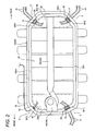
Fig. 2 is a plan view of abattery pack 18 having acover 52 removed, as seen from above. -
Fig. 3 is an exploded perspective view showing structure of thebattery pack 18. - Now, an embodiment of the invention will be described referring to the drawings.
- In this embodiment, description will be made referring to a case where the motor-driven vehicle which is provided with the battery case according to the invention is a plug-in hybrid vehicle which employs both an engine and a motor as drive sources.
- As shown in
Fig. 1 , the motor-drivenvehicle 10 includes avehicle body 12. Thevehicle body 12 is provided with anengine 14, afuel tank 16, abattery pack 18, afront inverter 20, arear inverter 22, a front driving motor 24, arear driving motor 26,auxiliary equipments 28, acharging section 30, and so on. It is to be noted that the front driving motor 24 and therear driving motor 26 correspond to the motor in this invention. - The
engine 14 drives front wheels 2 and rear wheels 4, and is provided between the front wheels 2 on right and left sides. - The
fuel tank 16 feeds fuel to theengine 14, and is provided between the rear wheels 4 on right and left sides. - The
battery pack 18 is arranged between the front wheels 2 and the rear wheels 4. Accordingly, theengine 14 is positioned in front of thebattery pack 18, and thefuel tank 16 is positioned in rear of thebattery pack 18. - Four lines of cables including front
high voltage cables 32, rearhigh voltage cables 34, alow voltage cable 36, andcharging cables 38 are connected to thebattery pack 18 at their one ends. Other ends of the four lines of the cables are respectively connected to devices which are mounted on thevehicle body 12. - The electric power is transmitted between the
battery pack 18 and the devices mounted on thevehicle body 12, through these four lines of the cables. - Specifically describing, the front
high voltage cables 32 supply a high voltage direct current which is supplied from thebattery pack 18, to thefront inverter 20. The front driving motor 24 receives an alternating current which is supplied from thefront inverter 20, thereby to drive the front wheels 2. - The rear
high voltage cables 34 supply a high voltage direct current which is supplied from thebattery pack 18, to therear inverter 22. Therear driving motor 26 receives an alternating current which is supplied from therear inverter 22, thereby to drive the rear wheels 4. - The
low voltage cable 36 supplies a low voltage direct current from a DC/DC converter 37 which is provided outside thebattery pack 18, for the purpose of actuating auxiliary components (relays, sensors, ECU, etc.) which are provided inside thebattery pack 18, although not shown in the drawings, or performs input and output of control signals. - The
auxiliary equipments 28 are connected to the DC/DC converter 37 through thelow voltage cable 39, and include head lights, an air conditioner, an audio unit, and so on which are actuated by a low voltage direct current supplied from the DC/DC converter 37. The DC/DC converter 37 is connected to therear inverter 22 through thehigh voltage cable 41. - The
charging cables 38 supply a charging electric power which is supplied from thecharging section 30, to thebattery pack 18. Thecharging section 30 charges thebattery pack 18 with the electric power which is supplied from a charging station provided outside the motor-drivenvehicle 10 or a commercial power supply. - Then, the
battery pack 18 will be specifically described. - As shown in
Figs. 2 and3 , thebattery pack 18 includes abattery case 40, and the aforesaid four lines of the cables are provided inside and outside thebattery case 40. - Inside the
battery case 40, there are contained and held abattery 42, air blowing means 44, first andsecond junction boxes - The
battery 42 includes a plurality ofbattery modules 42A which are connected to each other in series, via bus-bars which are not shown. Each of thebattery modules 42A is provided with a plurality of battery cells which are connected to each other in series. Thebattery modules 42A are contained in thebattery case 40, in a state where they are held inside atray 50 with a pressure plate which is not shown, and covered with acover 52. - The air blowing means 44 includes a blowing
fan 44A for circulating the air inside thebattery case 40, anevaporator 44B, and aduct 44C for circulating the air inside thebattery case 40 thereby to cool thebattery 42. - The first and
second junction boxes battery modules 42A, and are electrically connected to thebattery modules 42A through wiring members which are not shown. - The
first junction box 46 is electrically connected to one ends of the fronthigh voltage cables 32 and one end of thelow voltage cable 36. Thefirst junction box 46 supplies the high voltage power which is supplied from thebattery modules 42A to the fronthigh voltage cables 32, and at the same time, supplies the high voltage power which is supplied from thebattery modules 42A to thelow voltage cable 36, after the high voltage power has been converted to the low voltage power, using a DC/DC converter. - Moreover, the
second junction box 48 is electrically connected to one ends of the rearhigh voltage cables 34 and one ends of thecharging cables 38. Thesecond junction box 48 supplies the high voltage power which is supplied from thebattery modules 42A to the rearhigh voltage cables 34, and at the same time, supplies the charging power which is supplied from thecharging cables 38 to thebattery modules 42A. - The
battery case 40 includes thetray 50 and thecover 52. - The
battery case 40 has an oblong shape having its longitudinal direction aligned with a longitudinal direction of the motor-drivenvehicle 10, and is arranged in a center part in a lateral direction of the vehicle. - As shown in
Fig. 1 , thebattery case 40 is positioned between a pair ofside members 6 below the floor panel which is not shown. Thebattery case 40 is fitted to theside members 6 by means offitting members 54. - In this embodiment, the
fitting members 54 are respectively provided so as to protrude from right and left sides of a bottom wall of thetray 50 outward in a lateral direction of thetray 50. The fourfitting members 54 are provided on each of the right and left sides of thetray 50 at an interval in a longitudinal direction of thetray 50. All thefitting members 54 are respectively fastened to a pair of theside members 6 with bolts. - As shown in
Fig. 2 , thetray 50 has a shape of a box having at least two sides and provided with chamfers at positions where extensions of these two sides intersect, as seen in a plan view. - In this embodiment, the
tray 50 has an oblong shape (a rectangular shape) which is provided with chamfers at four corners, as seen in a plan view. - As shown in
Figs. 2 and3 , thetray 50 is formed in a shape of a box which is open at an upper side, having abottom wall 56, and a side wall 58 which is erected from an outer peripheral edge of thebottom wall 56. - The outer peripheral edge of the
bottom wall 56 includes two longer outerperipheral edges 5604 extending rectilinearly in parallel with each other, two shorter outerperipheral edges 5602 extending rectilinearly in parallel with each other in a direction perpendicular to the longer outerperipheral edges 5604. Moreover, the outer peripheral edge of thebottom wall 56 includes first to fourth chamfer forming outerperipheral edges peripheral edges 5604 and both ends of the shorter outerperipheral edges 5602. - The side wall 58 includes two
longer side walls 5804 in a shape of a flat plate which are respectively erected from the longer outerperipheral edges 5604, twoshorter side walls 5802 in a shape of a flat plate which are respectively erected from the shorter outerperipheral edges 5602. Moreover, the side wall 58 includes first to fourth chamfer formingside walls longer side walls 5804 and both ends of theshorter side walls 5802. - In this embodiment, the
tray 50 is formed by stamping a sheet metal, and in consideration of stamping thetray 50, the side wall 58 is provided with an extracting slope. Specifically, the twolonger side walls 5804, the twoshorter side walls 5802, and the four chamfer formingside walls 5810 to 5816 are respectively inclined in a direction of going apart from thebottom wall 56, as they are erected from thebottom wall 56. - Moreover, a
tray flange 5002 in a flat shape which is folded outward is formed on an entire circumference of an upper end of the side wall 58. - As shown in
Fig. 3 , first to fourthcable passing holes cables side walls - Each of the first, third and fourth
cable passing holes - As shown in
Fig. 2 ,connecter fitting members 68 are respectively attached to the first, third and fourthcable passing holes connecter fitting members 68 has a body part in a plate-like shape having a larger profile than thecable passing holes - The body parts are attached to inner faces of the first, third and fourth chamfer forming
side walls cable passing holes side walls -
Front connectors 70,rear connectors 72, and chargingconnectors 74 are respectively fitted to the connecter fitting holes in the body parts of theconnecter fitting members 68. It is possible to employ various known means, such as screws or adhesives, for fitting these connectors to the connector fitting holes. - As shown in
Fig. 2 , thefront connectors 70 are electrically connected to thefirst junction box 46 by means of wiring members which are not shown, and the cable connectors 76 (Fig. 1 ) which are provided at one ends of the fronthigh voltage cables 32 are connected to thefront connectors 70. In this manner, a high voltage power is supplied from thebattery 42 to the fronthigh voltage cables 32. - Therefore, the front
high voltage cables 32 are arranged inside and outside thebattery case 40, in the center part of the first chamfer formingside wall 5810, by way of the firstcable passing hole 60, thefront connectors 70 and thecable connectors 76. - As shown in
Fig. 2 , therear connectors 72 are electrically connected to thesecond junctionbox 48 by means of wiringmembers which are not shown, and the cable connectors 78 (Fig. 1 ) which are provided at one ends of the rearhigh voltage cables 34 are connected to therear connectors 72. In this manner, a high voltage power is supplied from thebattery 42 to the rearhigh voltage cables 34. - Therefore, the rear
high voltage cables 34 are arranged inside and outside thebattery case 40, at the position of thetray 50 where the fourth chamfer formingside wall 5816 is formed, by way of the fourthcable passing hole 66, therear connectors 74 and thecable connectors 78. - As shown in
Fig. 2 , the chargingconnectors 74 are electrically connected to thesecond junction box 48 by means of wiring members which are not shown, and the cable connectors 80 (Fig. 1 ) which are provided at one ends of the chargingcables 38 are connected to the chargingconnectors 74. In this manner, a charging power is supplied to thebattery 42 through the chargingcables 38. - Therefore, the charging
cables 38 are arranged inside and outside thebattery case 40, at the position of thetray 50 where the third chamfer formingside wall 5814 is formed, by way of the thirdcable passing hole 5814, the chargingconnectors 72, and thecable connectors 80. - As shown in
Fig. 2 , the secondcable passing hole 62 has a round shape. - An
annular grommet 82 formed of elastic material such as rubber is fitted to the secondcable passing hole 62. One end of thelow voltage cable 36 is connected to thefirst junction box 46 through a hole in thegrommet 82. Gaps between thegrommet 82, the secondcable passing hole 62 and thelow voltage cable 36 are sealed by elasticity of thegrommet 82. - Therefore, the
low voltage cable 36 is arranged inside and outside thebattery case 40, at the position of thetray 50 where the second chamfer formingside wall 5812 is formed, by way of the secondcable passing hole 62 and thegrommet 82. - As shown in
Fig. 3 , thecover 52 is provided with anupper wall 84 in a shape of a rectangular plate, and aside wall 86 which is suspended from a circumference of thisupper wall 84. - A lower end of this
side wall 86 is formed as acover flange 5202 having a flat and annular shape which can be engaged with thetray flange 5002. - Moreover, the
upper wall 84 is provided with aconvex part 8402 in which the wiring members and the air blowing means 44 inside thebattery case 40 are contained. - In this embodiment, the
cover 52 is formed of synthetic resin. - The
cover 52 has a rectangular shape which is provided with chamfers at four corners, when thecover 52 is seen in a plan view. - The
cover 52 is mounted on thetray 50, by fastening thecover flange 5202 to thetray flange 5002 with bolts, at a plurality of positions spaced in an extending direction of these flanges, in a state where thecover flange 5202 is superposed on thetray flange 5002. - In a state where the
cover 50 is mounted on thetray 50, a containing space is formed between them, and thebattery 42, the blowing means 44, the first andsecond junction boxes - Moreover, a packing (a seal member) which is not shown is interposed between the
cover flange 5202 and thetray flange 5002. - Accordingly, air tightness of the containing space is enhanced by this packing, the aforesaid packings between the respective
connector fitting members 68 and thetray 50, and theaforesaid grommet 82 which is fitted to the second hole. - Then, operation and effects will be described.
- According to this embodiment, in case where the
tray 50 is seen in a plan view, thetray 50 has such a shape that the chamfers are formed at the positions where the extensions of the two sides intersect. Thecables battery 42 with the devices which are mounted on the motor-drivenvehicle 10 are arranged inside and outside thebattery case 40, at the positions of thetray 50 where the chamfers are formed. - Therefore, spaces S having a triangular shape in a plan view are respectively secured outside the
tray 50, at the positions where the chamfers are formed. Specifically, these triangular spaces S are interposed between thetray 50 and the structural members such as theengine 14 or thefuel tank 16 existing adjacent to thebattery case 40. - For this reason, in case where the structural members such as the
engine 14 or thefuel tank 16 existing adjacent to thebattery case 40 are displaced so as to approach thetray 50, when the other motor-drivenvehicle 10 collides against the motor-drivenvehicle 10, for example, the shorter outerperipheral edges 5602 are butted against these structural members, and theshorter side walls 5802 are also butted against the structural members. - Therefore, because of the triangular spaces S which are secured between the structural members and the
tray 50, it is possible to prevent the structural members from exerting constrained forces on the cables or the connectors. In this manner, durability of the cables and connectors can be advantageously enhanced. - Moreover, in case where the
tray 50 is formed by stamping the sheet metal, in such a shape that thetray 50 is not provided with the chamfers, as seen in a plan view, at the positions where the extensions of the two sides intersect, constrained forces are exerted on corner parts during the stamping work. This is disadvantageous in conducting the stamping work. - In this embodiment, because the
tray 50 is provided with the chamfers, as seen in a plan view, at the positions where the extensions of the two sides intersect, there is no position in thetray 50 where the constrained forces are exerted during the stamping work. Therefore, this embodiment is advantageous in enabling thetray 50 to be easily formed by stamping. - Further, in case where the rear
high voltage cables 34 and the chargingcables 38 are intended to be arranged at the position of theshorter side wall 5802 at the rear side, it is required to arrange the rearhigh voltage cables 34 and the chargingcables 38 in a state forcibly folded at a small curvature, because a space between theshorter side wall 5802 at the rear side and thefuel tank 16 is narrow. Therefore, disadvantage occurs in enhancing freeness in arranging the cables outside thetray 50. - On the contrary, in this embodiment, the center parts of the third and fourth chamfer forming
side walls vehicle 10 than theshorter side wall 5802 at the rear side. Therefore, it is possible to secure the larger spaces S between the center parts of the third and fourth chamfer formingside walls fuel tank 16. Accordingly, it is possible to arrange the rearhigh voltage cables 34 and the chargingcables 38 in a state obtusely folded at a relatively large curvature, and hence, freeness in arranging the cables outside thetray 50 can be advantageously enhanced. - Moreover, in this embodiment, because the chamfer forming side walls are formed in a shape of a flat plate, it is possible to easily interpose the packings between the
connector fitting members 68 and the first, third, and fourth chamfer formingside walls grommet 82 to the secondcable passing hole 62 of the second chamfer formingside wall 5812. In short, the sealing materials such as the packing and thegrommet 82 can be easily fitted, which is advantageous in easily and reliably securing sealing performance at the positions where thecables battery case 40. - Further, in this embodiment, the
tray 50 has such a shape that the chamfers are formed at the four corners of a rectangular shape, as seen in a plan view, and thecables battery 42 to the devices mounted on the motor-drivenvehicle 10 are arranged inside and outside the battery case 4 0, at the positions of thetray 50 where the chamfers are formed. - Therefore, it is possible to arrange the
cables tray 50. Accordingly, freeness of layout of thecables cables vehicle body 12. - Moreover, the side wall 58 including the chamfer forming walls 58 are inclined so as to go apart from the side wall 58 as being erected from the
bottom wall 56. This is advantageous in facilitating the stamping work, because thetray 50 is formed by stamping the sheet metal. - Although in this embodiment, the description has been made referring to a case where the motor-driven
vehicle 10 provided with thebattery case 40 is the plug-in hybrid vehicle, it is of course possible to apply the invention to a hybrid vehicle in which thebattery 42 is not charged with an external power supply or an electric vehicle in which only a motor is used as a power supply. The invention is extensively applied to the motor-driven vehicles including these plug-in hybrid vehicle, hybrid vehicle, and electric vehicle. - 10...Motor-driven vehicle, 12...Vehicle body, 18...Battery pack, 20...Front inverter, 22...Rear inverter, 28...Auxiliary equipments, 30...Charging section, 32...Front high voltage cable, 34...Rear high voltage cable, 36...Low voltage cable, 38...Charging cable, 40...Battery case, 42...Battery, 50...Tray, 52...Cover, 56...Bottomwall, 5602...Shorter outer peripheral edge, 5604...Longer outer peripheral edge, 5610...First chamfer forming outer peripheral edge, 5612...Second chamfer forming outer peripheral edge, 5614...Third chamfer forming outer peripheral edge, 5616...Fourth chamfer forming outer peripheral edge, 58...Side wall, 5802...Shorter side wall, 5804...Longer side wall, 5810...First chamfer forming side wall, 5812...Second chamfer forming side wall, 5814...Third chamfer forming side wall, 5816...Fourth chamfer forming side wall
Claims (5)
- A battery case mounted on a motor-driven vehicle and including a tray which contains a battery for supplying an electric power to a motor for driving the motor-driven vehicle, characterized in that,
as seen in a plan view, the tray has a shape of a box having at least two sides and formed with a chamfer at a position where extensions of the two sides intersect, and
the tray is provided with a cable passing hole through which a cable for connecting the battery to a device mounted on the motor-driven vehicle can be passed, at a position of the tray where the chamfer is formed. - The battery case as claimed in claim 1, characterized in that
the tray includes a bottom wall, and a side wall which is erected from an outer peripheral edge of the bottom wall,
the chamfer is formed by a chamfer forming outer peripheral edge which is formed in a part of the outer peripheral edge of the bottom wall, and by a chamfer forming side wall which is formed of a part of the side wall erected from the chamfer forming outer peripheral edge, and
the cable passing hole is provided in the chamfer forming side wall. - The battery case as claimed in claim 2, characterized in that
the chamfer forming side wall is formed in a shape of a flat plate. - The battery case as claimed in any one of claims 1 to 3, characterized in that
the shape of the box is such a shape that the chamfers are formed at four corners of a rectangular shape. - The battery case as claimed in any one of claims 2 to 4, characterized in that
the side wall including the chamfer forming side wall is inclined so as to go apart from the bottom wall, as being erected from the bottom wall, and
the tray is formed by stamping a sheet metal.
Applications Claiming Priority (2)
| Application Number | Priority Date | Filing Date | Title |
|---|---|---|---|
| JP2012124562A JP6094060B2 (en) | 2012-05-31 | 2012-05-31 | Battery case |
| PCT/JP2013/063808 WO2013179917A1 (en) | 2012-05-31 | 2013-05-17 | Battery case |
Publications (3)
| Publication Number | Publication Date |
|---|---|
| EP2858140A1 true EP2858140A1 (en) | 2015-04-08 |
| EP2858140A4 EP2858140A4 (en) | 2015-12-23 |
| EP2858140B1 EP2858140B1 (en) | 2016-12-14 |
Family
ID=49673120
Family Applications (1)
| Application Number | Title | Priority Date | Filing Date |
|---|---|---|---|
| EP13797761.7A Active EP2858140B1 (en) | 2012-05-31 | 2013-05-17 | Battery case |
Country Status (6)
| Country | Link |
|---|---|
| US (1) | US20150147618A1 (en) |
| EP (1) | EP2858140B1 (en) |
| JP (1) | JP6094060B2 (en) |
| CN (1) | CN104396045B (en) |
| AU (1) | AU2013268732B2 (en) |
| WO (1) | WO2013179917A1 (en) |
Cited By (3)
| Publication number | Priority date | Publication date | Assignee | Title |
|---|---|---|---|---|
| WO2018211195A1 (en) * | 2017-05-18 | 2018-11-22 | Psa Automobiles Sa | Vehicle with optional electric drive machine coupling a non-diversifiable battery to a charger |
| WO2019233668A1 (en) | 2018-06-07 | 2019-12-12 | Mahle International Gmbh | Storage battery arrangement and method for producing a storage battery arrangement |
| EP3744546A3 (en) * | 2019-05-07 | 2021-03-10 | Yazaki Corporation | Vehicle cooling system and wire harness cooling structure |
Families Citing this family (24)
| Publication number | Priority date | Publication date | Assignee | Title |
|---|---|---|---|---|
| JP6245518B2 (en) | 2014-02-27 | 2017-12-13 | 三菱自動車工業株式会社 | Electric connector mounting structure for battery pack for electric vehicle |
| JP6287375B2 (en) * | 2014-03-11 | 2018-03-07 | 三菱自動車工業株式会社 | Battery pack temperature control device |
| JP6284016B2 (en) * | 2014-03-25 | 2018-02-28 | 三菱自動車工業株式会社 | Electric vehicle |
| DE102014108160A1 (en) * | 2014-06-11 | 2015-12-17 | Dr. Ing. H.C. F. Porsche Aktiengesellschaft | Underbody unit for a motor vehicle |
| JP6361329B2 (en) * | 2014-07-04 | 2018-07-25 | 三菱自動車工業株式会社 | Battery pack cable connection structure |
| JP6340960B2 (en) | 2014-07-07 | 2018-06-13 | 三菱自動車工業株式会社 | Vehicle battery pack temperature control device |
| JP6906913B2 (en) * | 2016-08-29 | 2021-07-21 | 三洋電機株式会社 | A power supply unit for vehicles and an electric vehicle equipped with this power supply unit |
| JP6442451B2 (en) * | 2016-09-02 | 2018-12-19 | 本田技研工業株式会社 | Case structure of power equipment unit |
| HRP20221219T1 (en) * | 2017-02-17 | 2022-12-23 | Mubea Carbo Tech Gmbh | Battery structure and protector |
| JP6683744B2 (en) * | 2018-01-23 | 2020-04-22 | 本田技研工業株式会社 | Vehicle battery unit |
| JP7042160B2 (en) * | 2018-05-28 | 2022-03-25 | ダイムラー・アクチェンゲゼルシャフト | Electric vehicle |
| JP2019209850A (en) * | 2018-06-05 | 2019-12-12 | 株式会社デンソー | Vehicle battery pack |
| JP7061522B2 (en) * | 2018-06-27 | 2022-04-28 | 本田技研工業株式会社 | Battery pack and electric vehicle |
| DE102018213009A1 (en) * | 2018-08-03 | 2020-02-06 | Bayerische Motoren Werke Aktiengesellschaft | Fastening arrangement for a vehicle battery on a body of a motor vehicle and method for mounting a vehicle battery in a motor vehicle |
| JP6724091B2 (en) * | 2018-09-06 | 2020-07-15 | 本田技研工業株式会社 | Hybrid vehicle |
| US11367918B2 (en) * | 2018-11-13 | 2022-06-21 | Rivian Ip Holdings, Llc | Electric vehicle battery pack having external side pouch for electrical components |
| JP2020074278A (en) * | 2019-10-07 | 2020-05-14 | 株式会社エンビジョンAescジャパン | Battery pack |
| KR20210129534A (en) * | 2020-04-20 | 2021-10-28 | 현대자동차주식회사 | Power supply system for vehicle |
| CN112259854A (en) * | 2020-09-27 | 2021-01-22 | 中国第一汽车股份有限公司 | Power battery assembly and automobile |
| JP7563269B2 (en) * | 2021-03-26 | 2024-10-08 | マツダ株式会社 | Electric vehicle undercarriage |
| JP7348234B2 (en) * | 2021-06-23 | 2023-09-20 | 矢崎総業株式会社 | Automotive systems and junction boxes |
| CN113997787B (en) * | 2021-10-27 | 2024-03-08 | 的卢技术有限公司 | Energy modularized integrated system for electric vehicle |
| CN119095734A (en) * | 2023-03-30 | 2024-12-06 | 株式会社斯巴鲁 | Battery cell |
| CN117583733A (en) * | 2024-01-08 | 2024-02-23 | 张子斌 | Laser welding method of tank body and compressor shell |
Family Cites Families (11)
| Publication number | Priority date | Publication date | Assignee | Title |
|---|---|---|---|---|
| US2265348A (en) * | 1939-03-16 | 1941-12-09 | Arthur E Cole | Ice tray and grid |
| CN2409616Y (en) * | 2000-01-21 | 2000-12-06 | 深圳市雄韬电源科技有限公司 | Sealed lead-acid accumulator |
| JP2006040547A (en) * | 2004-07-22 | 2006-02-09 | Sanyo Electric Co Ltd | Power supply device for vehicle |
| JP5210500B2 (en) * | 2006-05-10 | 2013-06-12 | トヨタ自動車株式会社 | Power storage device |
| JP4812529B2 (en) * | 2006-06-14 | 2011-11-09 | トヨタ自動車株式会社 | Power supply device and vehicle |
| JP4389930B2 (en) * | 2006-12-28 | 2009-12-24 | 三菱自動車工業株式会社 | Battery case structure for electric vehicles |
| JP5298618B2 (en) * | 2008-04-25 | 2013-09-25 | 日産自動車株式会社 | In-vehicle structure of wiring protection tube and storage battery using the same |
| JP5531626B2 (en) * | 2009-05-26 | 2014-06-25 | 日産自動車株式会社 | Vehicle battery assembly cooling structure and battery assembly with water jacket |
| JP5360689B2 (en) * | 2009-09-24 | 2013-12-04 | スズキ株式会社 | Vehicle high-voltage cable routing structure |
| JP5394294B2 (en) | 2010-03-23 | 2014-01-22 | 株式会社オーテックジャパン | Battery case drainage device |
| JP5321554B2 (en) * | 2010-08-31 | 2013-10-23 | トヨタ自動車株式会社 | Power storage device and vehicle |
-
2012
- 2012-05-31 JP JP2012124562A patent/JP6094060B2/en active Active
-
2013
- 2013-05-17 AU AU2013268732A patent/AU2013268732B2/en active Active
- 2013-05-17 WO PCT/JP2013/063808 patent/WO2013179917A1/en not_active Ceased
- 2013-05-17 CN CN201380029023.9A patent/CN104396045B/en active Active
- 2013-05-17 EP EP13797761.7A patent/EP2858140B1/en active Active
- 2013-05-17 US US14/404,576 patent/US20150147618A1/en not_active Abandoned
Cited By (7)
| Publication number | Priority date | Publication date | Assignee | Title |
|---|---|---|---|---|
| WO2018211195A1 (en) * | 2017-05-18 | 2018-11-22 | Psa Automobiles Sa | Vehicle with optional electric drive machine coupling a non-diversifiable battery to a charger |
| FR3066448A1 (en) * | 2017-05-18 | 2018-11-23 | Peugeot Citroen Automobiles Sa | VEHICLE WITH OPTIONAL ELECTRIC MOTOR MACHINE COUPLING A NON-DIVERSIBLE BATTERY WITH A CHARGER |
| CN110678348A (en) * | 2017-05-18 | 2020-01-10 | 标致雪铁龙汽车股份有限公司 | Vehicle with optional electric prime mover coupling the same battery to charger |
| CN110678348B (en) * | 2017-05-18 | 2023-02-24 | 标致雪铁龙汽车股份有限公司 | Vehicles with an optional electric prime mover coupling the same battery to a charger |
| WO2019233668A1 (en) | 2018-06-07 | 2019-12-12 | Mahle International Gmbh | Storage battery arrangement and method for producing a storage battery arrangement |
| DE102018209045A1 (en) | 2018-06-07 | 2019-12-12 | Mahle International Gmbh | Accumulator assembly and a method of manufacturing an accumulator assembly |
| EP3744546A3 (en) * | 2019-05-07 | 2021-03-10 | Yazaki Corporation | Vehicle cooling system and wire harness cooling structure |
Also Published As
| Publication number | Publication date |
|---|---|
| JP6094060B2 (en) | 2017-03-15 |
| WO2013179917A1 (en) | 2013-12-05 |
| CN104396045A (en) | 2015-03-04 |
| AU2013268732B2 (en) | 2015-11-19 |
| EP2858140B1 (en) | 2016-12-14 |
| JP2013251111A (en) | 2013-12-12 |
| AU2013268732A1 (en) | 2014-12-18 |
| CN104396045B (en) | 2017-03-08 |
| US20150147618A1 (en) | 2015-05-28 |
| EP2858140A4 (en) | 2015-12-23 |
Similar Documents
| Publication | Publication Date | Title |
|---|---|---|
| EP2858140B1 (en) | Battery case | |
| US10434861B2 (en) | Power equipment unit and vehicle | |
| US10661668B2 (en) | Power conversion apparatus and junction box | |
| EP2897195B1 (en) | Pressure release structure for vehicle battery pack | |
| US9485881B2 (en) | Inverter cover | |
| CN103781651B (en) | There is the automobile of elec. vehicle CD-ROM drive motor | |
| US9187050B2 (en) | Harness routing structure for electric vehicle | |
| US20180075996A1 (en) | Harness holder, power equipment unit, and vehicle | |
| US9586543B2 (en) | Electric vehicle | |
| US9236680B2 (en) | Connector and vehicle including connector | |
| KR102610042B1 (en) | integrated high voltage junction unit for electric vehicle | |
| JP2011100619A (en) | Power supply apparatus and vehicle with the same, and waterproof case | |
| JP6124008B2 (en) | Power converter | |
| US9531091B2 (en) | Cable connecting structure of battery pack | |
| WO2017110138A1 (en) | Mounting structure for high-voltage control device unit | |
| JP2015026428A (en) | Battery pack harness protection structure | |
| JP2014203770A (en) | Power storage device | |
| US20170106734A1 (en) | Vehicle | |
| JP5693536B2 (en) | Vehicle connection structure | |
| JP5895072B2 (en) | Vehicle connection structure | |
| CN115431771B (en) | On-board electrical equipment | |
| JP2020089004A (en) | Power converter | |
| JP7427968B2 (en) | battery pack | |
| JP6563765B2 (en) | Battery pack |
Legal Events
| Date | Code | Title | Description |
|---|---|---|---|
| PUAI | Public reference made under article 153(3) epc to a published international application that has entered the european phase |
Free format text: ORIGINAL CODE: 0009012 |
|
| 17P | Request for examination filed |
Effective date: 20141231 |
|
| AK | Designated contracting states |
Kind code of ref document: A1 Designated state(s): AL AT BE BG CH CY CZ DE DK EE ES FI FR GB GR HR HU IE IS IT LI LT LU LV MC MK MT NL NO PL PT RO RS SE SI SK SM TR |
|
| AX | Request for extension of the european patent |
Extension state: BA ME |
|
| DAX | Request for extension of the european patent (deleted) | ||
| RA4 | Supplementary search report drawn up and despatched (corrected) |
Effective date: 20151124 |
|
| RIC1 | Information provided on ipc code assigned before grant |
Ipc: B60L 11/18 20060101ALI20151118BHEP Ipc: B60K 1/04 20060101ALI20151118BHEP Ipc: H01M 2/10 20060101AFI20151118BHEP |
|
| GRAP | Despatch of communication of intention to grant a patent |
Free format text: ORIGINAL CODE: EPIDOSNIGR1 |
|
| INTG | Intention to grant announced |
Effective date: 20160622 |
|
| GRAS | Grant fee paid |
Free format text: ORIGINAL CODE: EPIDOSNIGR3 |
|
| GRAA | (expected) grant |
Free format text: ORIGINAL CODE: 0009210 |
|
| AK | Designated contracting states |
Kind code of ref document: B1 Designated state(s): AL AT BE BG CH CY CZ DE DK EE ES FI FR GB GR HR HU IE IS IT LI LT LU LV MC MK MT NL NO PL PT RO RS SE SI SK SM TR |
|
| REG | Reference to a national code |
Ref country code: GB Ref legal event code: FG4D |
|
| REG | Reference to a national code |
Ref country code: CH Ref legal event code: EP |
|
| REG | Reference to a national code |
Ref country code: IE Ref legal event code: FG4D |
|
| REG | Reference to a national code |
Ref country code: AT Ref legal event code: REF Ref document number: 854313 Country of ref document: AT Kind code of ref document: T Effective date: 20170115 |
|
| REG | Reference to a national code |
Ref country code: DE Ref legal event code: R096 Ref document number: 602013015439 Country of ref document: DE |
|
| PG25 | Lapsed in a contracting state [announced via postgrant information from national office to epo] |
Ref country code: LV Free format text: LAPSE BECAUSE OF FAILURE TO SUBMIT A TRANSLATION OF THE DESCRIPTION OR TO PAY THE FEE WITHIN THE PRESCRIBED TIME-LIMIT Effective date: 20161214 |
|
| REG | Reference to a national code |
Ref country code: LT Ref legal event code: MG4D |
|
| REG | Reference to a national code |
Ref country code: NL Ref legal event code: MP Effective date: 20161214 |
|
| PG25 | Lapsed in a contracting state [announced via postgrant information from national office to epo] |
Ref country code: NO Free format text: LAPSE BECAUSE OF FAILURE TO SUBMIT A TRANSLATION OF THE DESCRIPTION OR TO PAY THE FEE WITHIN THE PRESCRIBED TIME-LIMIT Effective date: 20170314 Ref country code: LT Free format text: LAPSE BECAUSE OF FAILURE TO SUBMIT A TRANSLATION OF THE DESCRIPTION OR TO PAY THE FEE WITHIN THE PRESCRIBED TIME-LIMIT Effective date: 20161214 Ref country code: SE Free format text: LAPSE BECAUSE OF FAILURE TO SUBMIT A TRANSLATION OF THE DESCRIPTION OR TO PAY THE FEE WITHIN THE PRESCRIBED TIME-LIMIT Effective date: 20161214 Ref country code: GR Free format text: LAPSE BECAUSE OF FAILURE TO SUBMIT A TRANSLATION OF THE DESCRIPTION OR TO PAY THE FEE WITHIN THE PRESCRIBED TIME-LIMIT Effective date: 20170315 |
|
| REG | Reference to a national code |
Ref country code: FR Ref legal event code: PLFP Year of fee payment: 5 |
|
| REG | Reference to a national code |
Ref country code: AT Ref legal event code: MK05 Ref document number: 854313 Country of ref document: AT Kind code of ref document: T Effective date: 20161214 |
|
| PG25 | Lapsed in a contracting state [announced via postgrant information from national office to epo] |
Ref country code: FI Free format text: LAPSE BECAUSE OF FAILURE TO SUBMIT A TRANSLATION OF THE DESCRIPTION OR TO PAY THE FEE WITHIN THE PRESCRIBED TIME-LIMIT Effective date: 20161214 Ref country code: HR Free format text: LAPSE BECAUSE OF FAILURE TO SUBMIT A TRANSLATION OF THE DESCRIPTION OR TO PAY THE FEE WITHIN THE PRESCRIBED TIME-LIMIT Effective date: 20161214 Ref country code: RS Free format text: LAPSE BECAUSE OF FAILURE TO SUBMIT A TRANSLATION OF THE DESCRIPTION OR TO PAY THE FEE WITHIN THE PRESCRIBED TIME-LIMIT Effective date: 20161214 |
|
| PG25 | Lapsed in a contracting state [announced via postgrant information from national office to epo] |
Ref country code: NL Free format text: LAPSE BECAUSE OF FAILURE TO SUBMIT A TRANSLATION OF THE DESCRIPTION OR TO PAY THE FEE WITHIN THE PRESCRIBED TIME-LIMIT Effective date: 20161214 |
|
| PG25 | Lapsed in a contracting state [announced via postgrant information from national office to epo] |
Ref country code: EE Free format text: LAPSE BECAUSE OF FAILURE TO SUBMIT A TRANSLATION OF THE DESCRIPTION OR TO PAY THE FEE WITHIN THE PRESCRIBED TIME-LIMIT Effective date: 20161214 Ref country code: CZ Free format text: LAPSE BECAUSE OF FAILURE TO SUBMIT A TRANSLATION OF THE DESCRIPTION OR TO PAY THE FEE WITHIN THE PRESCRIBED TIME-LIMIT Effective date: 20161214 Ref country code: RO Free format text: LAPSE BECAUSE OF FAILURE TO SUBMIT A TRANSLATION OF THE DESCRIPTION OR TO PAY THE FEE WITHIN THE PRESCRIBED TIME-LIMIT Effective date: 20161214 Ref country code: SK Free format text: LAPSE BECAUSE OF FAILURE TO SUBMIT A TRANSLATION OF THE DESCRIPTION OR TO PAY THE FEE WITHIN THE PRESCRIBED TIME-LIMIT Effective date: 20161214 Ref country code: IS Free format text: LAPSE BECAUSE OF FAILURE TO SUBMIT A TRANSLATION OF THE DESCRIPTION OR TO PAY THE FEE WITHIN THE PRESCRIBED TIME-LIMIT Effective date: 20170414 |
|
| PG25 | Lapsed in a contracting state [announced via postgrant information from national office to epo] |
Ref country code: IT Free format text: LAPSE BECAUSE OF FAILURE TO SUBMIT A TRANSLATION OF THE DESCRIPTION OR TO PAY THE FEE WITHIN THE PRESCRIBED TIME-LIMIT Effective date: 20161214 Ref country code: LU Free format text: LAPSE BECAUSE OF NON-PAYMENT OF DUE FEES Effective date: 20170531 Ref country code: SM Free format text: LAPSE BECAUSE OF FAILURE TO SUBMIT A TRANSLATION OF THE DESCRIPTION OR TO PAY THE FEE WITHIN THE PRESCRIBED TIME-LIMIT Effective date: 20161214 Ref country code: PT Free format text: LAPSE BECAUSE OF FAILURE TO SUBMIT A TRANSLATION OF THE DESCRIPTION OR TO PAY THE FEE WITHIN THE PRESCRIBED TIME-LIMIT Effective date: 20170414 Ref country code: BG Free format text: LAPSE BECAUSE OF FAILURE TO SUBMIT A TRANSLATION OF THE DESCRIPTION OR TO PAY THE FEE WITHIN THE PRESCRIBED TIME-LIMIT Effective date: 20170314 Ref country code: ES Free format text: LAPSE BECAUSE OF FAILURE TO SUBMIT A TRANSLATION OF THE DESCRIPTION OR TO PAY THE FEE WITHIN THE PRESCRIBED TIME-LIMIT Effective date: 20161214 Ref country code: PL Free format text: LAPSE BECAUSE OF FAILURE TO SUBMIT A TRANSLATION OF THE DESCRIPTION OR TO PAY THE FEE WITHIN THE PRESCRIBED TIME-LIMIT Effective date: 20161214 Ref country code: BE Free format text: LAPSE BECAUSE OF FAILURE TO SUBMIT A TRANSLATION OF THE DESCRIPTION OR TO PAY THE FEE WITHIN THE PRESCRIBED TIME-LIMIT Effective date: 20161214 Ref country code: AT Free format text: LAPSE BECAUSE OF FAILURE TO SUBMIT A TRANSLATION OF THE DESCRIPTION OR TO PAY THE FEE WITHIN THE PRESCRIBED TIME-LIMIT Effective date: 20161214 |
|
| REG | Reference to a national code |
Ref country code: DE Ref legal event code: R097 Ref document number: 602013015439 Country of ref document: DE |
|
| PLBE | No opposition filed within time limit |
Free format text: ORIGINAL CODE: 0009261 |
|
| STAA | Information on the status of an ep patent application or granted ep patent |
Free format text: STATUS: NO OPPOSITION FILED WITHIN TIME LIMIT |
|
| 26N | No opposition filed |
Effective date: 20170915 |
|
| PG25 | Lapsed in a contracting state [announced via postgrant information from national office to epo] |
Ref country code: DK Free format text: LAPSE BECAUSE OF FAILURE TO SUBMIT A TRANSLATION OF THE DESCRIPTION OR TO PAY THE FEE WITHIN THE PRESCRIBED TIME-LIMIT Effective date: 20161214 |
|
| REG | Reference to a national code |
Ref country code: CH Ref legal event code: PL |
|
| GBPC | Gb: european patent ceased through non-payment of renewal fee |
Effective date: 20170517 |
|
| PG25 | Lapsed in a contracting state [announced via postgrant information from national office to epo] |
Ref country code: MC Free format text: LAPSE BECAUSE OF FAILURE TO SUBMIT A TRANSLATION OF THE DESCRIPTION OR TO PAY THE FEE WITHIN THE PRESCRIBED TIME-LIMIT Effective date: 20161214 |
|
| REG | Reference to a national code |
Ref country code: IE Ref legal event code: MM4A |
|
| PG25 | Lapsed in a contracting state [announced via postgrant information from national office to epo] |
Ref country code: SI Free format text: LAPSE BECAUSE OF FAILURE TO SUBMIT A TRANSLATION OF THE DESCRIPTION OR TO PAY THE FEE WITHIN THE PRESCRIBED TIME-LIMIT Effective date: 20161214 Ref country code: LI Free format text: LAPSE BECAUSE OF NON-PAYMENT OF DUE FEES Effective date: 20170531 Ref country code: CH Free format text: LAPSE BECAUSE OF NON-PAYMENT OF DUE FEES Effective date: 20170531 |
|
| PG25 | Lapsed in a contracting state [announced via postgrant information from national office to epo] |
Ref country code: LU Free format text: LAPSE BECAUSE OF NON-PAYMENT OF DUE FEES Effective date: 20170517 |
|
| REG | Reference to a national code |
Ref country code: FR Ref legal event code: PLFP Year of fee payment: 6 |
|
| PG25 | Lapsed in a contracting state [announced via postgrant information from national office to epo] |
Ref country code: GB Free format text: LAPSE BECAUSE OF NON-PAYMENT OF DUE FEES Effective date: 20170517 Ref country code: IE Free format text: LAPSE BECAUSE OF NON-PAYMENT OF DUE FEES Effective date: 20170517 |
|
| PG25 | Lapsed in a contracting state [announced via postgrant information from national office to epo] |
Ref country code: MT Free format text: LAPSE BECAUSE OF NON-PAYMENT OF DUE FEES Effective date: 20170517 |
|
| PG25 | Lapsed in a contracting state [announced via postgrant information from national office to epo] |
Ref country code: HU Free format text: LAPSE BECAUSE OF FAILURE TO SUBMIT A TRANSLATION OF THE DESCRIPTION OR TO PAY THE FEE WITHIN THE PRESCRIBED TIME-LIMIT; INVALID AB INITIO Effective date: 20130517 |
|
| PG25 | Lapsed in a contracting state [announced via postgrant information from national office to epo] |
Ref country code: CY Free format text: LAPSE BECAUSE OF FAILURE TO SUBMIT A TRANSLATION OF THE DESCRIPTION OR TO PAY THE FEE WITHIN THE PRESCRIBED TIME-LIMIT Effective date: 20161214 |
|
| PG25 | Lapsed in a contracting state [announced via postgrant information from national office to epo] |
Ref country code: MK Free format text: LAPSE BECAUSE OF FAILURE TO SUBMIT A TRANSLATION OF THE DESCRIPTION OR TO PAY THE FEE WITHIN THE PRESCRIBED TIME-LIMIT Effective date: 20161214 |
|
| PG25 | Lapsed in a contracting state [announced via postgrant information from national office to epo] |
Ref country code: TR Free format text: LAPSE BECAUSE OF FAILURE TO SUBMIT A TRANSLATION OF THE DESCRIPTION OR TO PAY THE FEE WITHIN THE PRESCRIBED TIME-LIMIT Effective date: 20161214 |
|
| PG25 | Lapsed in a contracting state [announced via postgrant information from national office to epo] |
Ref country code: AL Free format text: LAPSE BECAUSE OF FAILURE TO SUBMIT A TRANSLATION OF THE DESCRIPTION OR TO PAY THE FEE WITHIN THE PRESCRIBED TIME-LIMIT Effective date: 20161214 |
|
| REG | Reference to a national code |
Ref country code: DE Ref legal event code: R079 Ref document number: 602013015439 Country of ref document: DE Free format text: PREVIOUS MAIN CLASS: H01M0002100000 Ipc: H01M0050200000 |
|
| REG | Reference to a national code |
Ref country code: FR Ref legal event code: PLFP Year of fee payment: 11 |
|
| PGFP | Annual fee paid to national office [announced via postgrant information from national office to epo] |
Ref country code: DE Payment date: 20250402 Year of fee payment: 13 |
|
| PGFP | Annual fee paid to national office [announced via postgrant information from national office to epo] |
Ref country code: FR Payment date: 20250401 Year of fee payment: 13 |