EP2857929B1 - Information processing apparatus, information processing system, and power control method - Google Patents
Information processing apparatus, information processing system, and power control method Download PDFInfo
- Publication number
- EP2857929B1 EP2857929B1 EP14181252.9A EP14181252A EP2857929B1 EP 2857929 B1 EP2857929 B1 EP 2857929B1 EP 14181252 A EP14181252 A EP 14181252A EP 2857929 B1 EP2857929 B1 EP 2857929B1
- Authority
- EP
- European Patent Office
- Prior art keywords
- state
- information processing
- processing apparatus
- mode
- isct
- Prior art date
- Legal status (The legal status is an assumption and is not a legal conclusion. Google has not performed a legal analysis and makes no representation as to the accuracy of the status listed.)
- Active
Links
- 230000010365 information processing Effects 0.000 title claims description 33
- 238000000034 method Methods 0.000 title claims description 13
- 238000012545 processing Methods 0.000 claims description 20
- 238000004891 communication Methods 0.000 claims description 12
- 238000010586 diagram Methods 0.000 description 16
- 230000004044 response Effects 0.000 description 16
- 230000004048 modification Effects 0.000 description 13
- 238000012986 modification Methods 0.000 description 13
- 230000006870 function Effects 0.000 description 8
- 238000010438 heat treatment Methods 0.000 description 8
- 230000000694 effects Effects 0.000 description 7
- 238000005516 engineering process Methods 0.000 description 5
- 230000002093 peripheral effect Effects 0.000 description 5
- 230000003287 optical effect Effects 0.000 description 4
- 238000004590 computer program Methods 0.000 description 3
- 239000004973 liquid crystal related substance Substances 0.000 description 3
- 239000004065 semiconductor Substances 0.000 description 3
- 101150012579 ADSL gene Proteins 0.000 description 2
- 102100020775 Adenylosuccinate lyase Human genes 0.000 description 2
- 108700040193 Adenylosuccinate lyases Proteins 0.000 description 2
- 241001422033 Thestylus Species 0.000 description 2
- 230000005540 biological transmission Effects 0.000 description 2
- 230000008859 change Effects 0.000 description 2
- 230000001678 irradiating effect Effects 0.000 description 2
- 229920001690 polydopamine Polymers 0.000 description 2
- 238000003825 pressing Methods 0.000 description 2
- 230000009471 action Effects 0.000 description 1
- 230000003213 activating effect Effects 0.000 description 1
- 230000004075 alteration Effects 0.000 description 1
- 230000006399 behavior Effects 0.000 description 1
- 230000008901 benefit Effects 0.000 description 1
- 238000013461 design Methods 0.000 description 1
- 230000002708 enhancing effect Effects 0.000 description 1
- 230000007246 mechanism Effects 0.000 description 1
- 230000008569 process Effects 0.000 description 1
- 230000009467 reduction Effects 0.000 description 1
- 230000007480 spreading Effects 0.000 description 1
- 230000000007 visual effect Effects 0.000 description 1
Images


Classifications
-
- G—PHYSICS
- G06—COMPUTING; CALCULATING OR COUNTING
- G06F—ELECTRIC DIGITAL DATA PROCESSING
- G06F1/00—Details not covered by groups G06F3/00 - G06F13/00 and G06F21/00
- G06F1/26—Power supply means, e.g. regulation thereof
- G06F1/32—Means for saving power
- G06F1/3203—Power management, i.e. event-based initiation of a power-saving mode
- G06F1/3234—Power saving characterised by the action undertaken
- G06F1/3287—Power saving characterised by the action undertaken by switching off individual functional units in the computer system
-
- G—PHYSICS
- G06—COMPUTING; CALCULATING OR COUNTING
- G06F—ELECTRIC DIGITAL DATA PROCESSING
- G06F1/00—Details not covered by groups G06F3/00 - G06F13/00 and G06F21/00
- G06F1/26—Power supply means, e.g. regulation thereof
- G06F1/32—Means for saving power
- G06F1/3203—Power management, i.e. event-based initiation of a power-saving mode
- G06F1/3234—Power saving characterised by the action undertaken
- G06F1/325—Power saving in peripheral device
- G06F1/3265—Power saving in display device
-
- G—PHYSICS
- G06—COMPUTING; CALCULATING OR COUNTING
- G06F—ELECTRIC DIGITAL DATA PROCESSING
- G06F1/00—Details not covered by groups G06F3/00 - G06F13/00 and G06F21/00
- G06F1/26—Power supply means, e.g. regulation thereof
- G06F1/32—Means for saving power
- G06F1/3203—Power management, i.e. event-based initiation of a power-saving mode
- G06F1/3206—Monitoring of events, devices or parameters that trigger a change in power modality
- G06F1/3231—Monitoring the presence, absence or movement of users
-
- G—PHYSICS
- G06—COMPUTING; CALCULATING OR COUNTING
- G06F—ELECTRIC DIGITAL DATA PROCESSING
- G06F1/00—Details not covered by groups G06F3/00 - G06F13/00 and G06F21/00
- G06F1/26—Power supply means, e.g. regulation thereof
- G06F1/32—Means for saving power
- G06F1/3203—Power management, i.e. event-based initiation of a power-saving mode
- G06F1/3234—Power saving characterised by the action undertaken
- G06F1/325—Power saving in peripheral device
- G06F1/3262—Power saving in digitizer or tablet
-
- G—PHYSICS
- G06—COMPUTING; CALCULATING OR COUNTING
- G06F—ELECTRIC DIGITAL DATA PROCESSING
- G06F1/00—Details not covered by groups G06F3/00 - G06F13/00 and G06F21/00
- G06F1/26—Power supply means, e.g. regulation thereof
- G06F1/32—Means for saving power
- G06F1/3203—Power management, i.e. event-based initiation of a power-saving mode
- G06F1/3234—Power saving characterised by the action undertaken
- G06F1/3296—Power saving characterised by the action undertaken by lowering the supply or operating voltage
-
- G—PHYSICS
- G06—COMPUTING; CALCULATING OR COUNTING
- G06F—ELECTRIC DIGITAL DATA PROCESSING
- G06F3/00—Input arrangements for transferring data to be processed into a form capable of being handled by the computer; Output arrangements for transferring data from processing unit to output unit, e.g. interface arrangements
- G06F3/01—Input arrangements or combined input and output arrangements for interaction between user and computer
- G06F3/03—Arrangements for converting the position or the displacement of a member into a coded form
- G06F3/041—Digitisers, e.g. for touch screens or touch pads, characterised by the transducing means
- G06F3/0416—Control or interface arrangements specially adapted for digitisers
-
- H—ELECTRICITY
- H04—ELECTRIC COMMUNICATION TECHNIQUE
- H04W—WIRELESS COMMUNICATION NETWORKS
- H04W52/00—Power management, e.g. TPC [Transmission Power Control], power saving or power classes
- H04W52/02—Power saving arrangements
- H04W52/0209—Power saving arrangements in terminal devices
- H04W52/0251—Power saving arrangements in terminal devices using monitoring of local events, e.g. events related to user activity
- H04W52/0254—Power saving arrangements in terminal devices using monitoring of local events, e.g. events related to user activity detecting a user operation or a tactile contact or a motion of the device
-
- H—ELECTRICITY
- H04—ELECTRIC COMMUNICATION TECHNIQUE
- H04W—WIRELESS COMMUNICATION NETWORKS
- H04W52/00—Power management, e.g. TPC [Transmission Power Control], power saving or power classes
- H04W52/02—Power saving arrangements
- H04W52/0209—Power saving arrangements in terminal devices
- H04W52/0261—Power saving arrangements in terminal devices managing power supply demand, e.g. depending on battery level
- H04W52/0267—Power saving arrangements in terminal devices managing power supply demand, e.g. depending on battery level by controlling user interface components
-
- G—PHYSICS
- G06—COMPUTING; CALCULATING OR COUNTING
- G06F—ELECTRIC DIGITAL DATA PROCESSING
- G06F1/00—Details not covered by groups G06F3/00 - G06F13/00 and G06F21/00
- G06F1/26—Power supply means, e.g. regulation thereof
-
- G—PHYSICS
- G06—COMPUTING; CALCULATING OR COUNTING
- G06F—ELECTRIC DIGITAL DATA PROCESSING
- G06F1/00—Details not covered by groups G06F3/00 - G06F13/00 and G06F21/00
- G06F1/26—Power supply means, e.g. regulation thereof
- G06F1/32—Means for saving power
-
- G—PHYSICS
- G06—COMPUTING; CALCULATING OR COUNTING
- G06F—ELECTRIC DIGITAL DATA PROCESSING
- G06F1/00—Details not covered by groups G06F3/00 - G06F13/00 and G06F21/00
- G06F1/26—Power supply means, e.g. regulation thereof
- G06F1/32—Means for saving power
- G06F1/3203—Power management, i.e. event-based initiation of a power-saving mode
-
- G—PHYSICS
- G06—COMPUTING; CALCULATING OR COUNTING
- G06F—ELECTRIC DIGITAL DATA PROCESSING
- G06F3/00—Input arrangements for transferring data to be processed into a form capable of being handled by the computer; Output arrangements for transferring data from processing unit to output unit, e.g. interface arrangements
- G06F3/01—Input arrangements or combined input and output arrangements for interaction between user and computer
- G06F3/048—Interaction techniques based on graphical user interfaces [GUI]
- G06F3/0487—Interaction techniques based on graphical user interfaces [GUI] using specific features provided by the input device, e.g. functions controlled by the rotation of a mouse with dual sensing arrangements, or of the nature of the input device, e.g. tap gestures based on pressure sensed by a digitiser
- G06F3/0488—Interaction techniques based on graphical user interfaces [GUI] using specific features provided by the input device, e.g. functions controlled by the rotation of a mouse with dual sensing arrangements, or of the nature of the input device, e.g. tap gestures based on pressure sensed by a digitiser using a touch-screen or digitiser, e.g. input of commands through traced gestures
-
- Y—GENERAL TAGGING OF NEW TECHNOLOGICAL DEVELOPMENTS; GENERAL TAGGING OF CROSS-SECTIONAL TECHNOLOGIES SPANNING OVER SEVERAL SECTIONS OF THE IPC; TECHNICAL SUBJECTS COVERED BY FORMER USPC CROSS-REFERENCE ART COLLECTIONS [XRACs] AND DIGESTS
- Y02—TECHNOLOGIES OR APPLICATIONS FOR MITIGATION OR ADAPTATION AGAINST CLIMATE CHANGE
- Y02D—CLIMATE CHANGE MITIGATION TECHNOLOGIES IN INFORMATION AND COMMUNICATION TECHNOLOGIES [ICT], I.E. INFORMATION AND COMMUNICATION TECHNOLOGIES AIMING AT THE REDUCTION OF THEIR OWN ENERGY USE
- Y02D10/00—Energy efficient computing, e.g. low power processors, power management or thermal management
-
- Y—GENERAL TAGGING OF NEW TECHNOLOGICAL DEVELOPMENTS; GENERAL TAGGING OF CROSS-SECTIONAL TECHNOLOGIES SPANNING OVER SEVERAL SECTIONS OF THE IPC; TECHNICAL SUBJECTS COVERED BY FORMER USPC CROSS-REFERENCE ART COLLECTIONS [XRACs] AND DIGESTS
- Y02—TECHNOLOGIES OR APPLICATIONS FOR MITIGATION OR ADAPTATION AGAINST CLIMATE CHANGE
- Y02D—CLIMATE CHANGE MITIGATION TECHNOLOGIES IN INFORMATION AND COMMUNICATION TECHNOLOGIES [ICT], I.E. INFORMATION AND COMMUNICATION TECHNOLOGIES AIMING AT THE REDUCTION OF THEIR OWN ENERGY USE
- Y02D30/00—Reducing energy consumption in communication networks
- Y02D30/70—Reducing energy consumption in communication networks in wireless communication networks
Definitions
- a movement to cause PCs to achieve operation (AOAC, always on always connect) achieved by such equipment is spreading.
- the PC10 is a so-called tablet type apparatus including a touchscreen in a display.
- FIG 1 shows the PC 100 including a display unit 102, a main button 104, and a power button 106.
- the power button 106 is a button for turning on and off the PC 100.
- the PC 100 performs processing such as turning on the power so as to shift into a running state (S0), or turning off the power.
- the keyboard and the touchpad are often controlled by systems such as the Basic Input/Output System (BIOS), an embedded controller (EC), and a keyboard controller (KBC).
- BIOS Basic Input/Output System
- EC embedded controller
- KBC keyboard controller
- the systems stop giving a notification to an OSs of equipment such as the keyboard and touchpad in the S0-iSCT state, and accordingly control can be performed.
- the system side can know the shift into S0-iSCT, but it is difficult for the system side to perform control so as to disable a notification to the OSs of equipment such as the keyboard and touchpad.
- the PC 100 when sifting into the S0-iSCT state, gives a notification indicating that the state of the PC 100 has shifted into the S0-iSCT state, to a program referred to as a utility program that operates on the OS executed by the PC 100. Subsequently, the utility program, which received a notification indicating that the state of the PC 100 has shifted into the S0-iSCT state, performs control so as to disable input to the input device such as the touchscreen, the keyboard, and the touchpad. According to such operation, the PC 100 according to the embodiment can prevent shifting into the running state (S0) even if input that the user does not intend is performed on the touchscreen, the keyboard, the touchpad, and the like in the S0-iSCT state.
- S0 running state
- the PC 100 includes an iSCT control module 112, BIOS/EC/KBC 114, a device control utility program 116, a touchscreen 118, and a wireless USB receiver/controller 119.
- the device control utility program 116 is software operating on an OS executed by the PC 100. According to a setting by the user, the device control utility program 116 switches enabling and disabling of an input device embedded in or connected with the PC 100. Alternatively, the device control utility program 116 switches enabling and disabling of input from the input device embedded in or connected with the PC 100 in a wireless or wired manner, according to a state of the sleep mode of the PC 100 that is switched by the BIOS/EC/KBC 114.
- the sleep mode is shifted from S0-iSCT state to the S0 state when the operation input is received.
- the device control utility program 116 When the device control utility program 116 receives, from the BIOS/EC/KBC 114, a notification that the sleep mode has shifted into the S0-iSCT state in the case where the PC 100 includes the wireless USB receiver/controller 119, the device control utility program 116 disables input from the input device connected with the wireless USB receiver/controller 119. By disabling the input from the input device connected with the wireless USB receiver/controller 119, the PC 100 can prevent a shift into the S0 state in the case of S0-iSCT state due to input operation to the wireless keyboard 132 or the wireless touchpad 134 that the user does not intend.
- the flowchart in FIG. 3 shows processing executed on a premise that the sleep mode of the PC 100 is the sleep state (S3).
- the sleep mode of the PC 100 is the sleep state (S3).
- the user keeps the PC 100 unused for a while, or the user presses the power button 106 so as to turn off the display unit 102.
- the iSCT control module 112 When the iSCT control module 112 receives, from the BIOS/EC/KBC 114, a notification that the PC 100 is in the sleep state (S3), the iSCT control module 112 periodically (for example, every 15 minutes during a day, and every 2 hours during a night) confirms whether the condition for a shift into the S0-iSCT state is satisfied (Step S101). Subsequently, if the condition for a shift into the S0-iSCT state is satisfied, the iSCT control module 112 notifies the BIOS/EC/KBC 114 to periodically shift into the S0-iSCT state. When the BIOS/EC/KBC 114 receives, from the iSCT control module 112, the notification to shift into the S0-iSCT state, the BIOS/EC/KBC 114 shifts the sleep mode into the S0-iSCT state.
- the sleep mode has shifted into the S0-iSCT state, update processing of information such as receiving an e-mail has been executed, the update processing has been completed, and then the PC 100 shifts the sleep mode into the sleep state (S3) again (Step S104).
- the BIOS/EC/KBC 114 After shifting into the S3 state, the BIOS/EC/KBC 114 notifies the device control utility program 116 of shifting into the S3 state (Step S105).
- the form in which the lid is closed in the state where the embedded display is not exposed may be referred to as a "clamshell mode”
- the form in which the lid is closed in a state where the embedded display is exposed may be referred to as a "tablet mode” with regard to such apparatus having at least two forms.
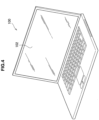
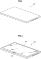
- FIGS. 4 to 6 are explanatory diagrams showing appearance examples of a PC 100 according to the first embodiment of the present disclosure.
- FIG. 4 is an appearance example of a state where a lid of the PC 100 is opened
- FIG. 5 is an appearance example of a state where the PC 100 is in the clamshell mode
- FIG. 6 is an appearance example of a state where the PC 100 is in the tablet mode.
- the PC 100 may determine whether input from the device is to be disabled in accordance with how the lid is closed. That is, in the case of the clamshell mode as shown in FIG. 5 , touch that the user does not intend is not performed on the touchscreen. However, in the case of the tablet mode as shown in FIG. 6 , the touch that the user does not intend may be performed. Accordingly, only in the case of the tablet mode as shown in FIG. 6 , the PC 100 disables the input from the device when the sleep mode is the S0-iSCT state.
- FIG. 7 is a flowchart showing an operation example of the PC 100 according to a modification of the first embodiment of the present disclosure.
- FIG. 7 shows an operation example of the PC 100 when input from the device is to be enabled or disabled depending on the sleep mode of the PC 100 or the form of the PC 100.
- the operation example of the PC 100 according to the modification of the first embodiment of the present disclosure will be explained.
- the iSCT control module 112 periodically confirms whether the condition for a shift into the S0-iSCT state is satisfied (Step S111).
- the BIOS/EC/KBC 114 receives, from the iSCT control module 112, the notification to shift into the S0-iSCT state, the BIOS/EC/KBC 114 shifts the sleep mode into the S0-iSCT state.
- the PC 100 can prevent the sleep mode from shifting into the S0 state in response to input operation that the user does not intend in the case where the sleep mode is S0-iSCT state and the form is the tablet mode. Accordingly, the PC 100 according to the modification of the first embodiment of the present disclosure can prevent an unexpected shift into a running state in a bag, and can prevent heating and unnecessary consumption of battery from occurring in association with the running in the case where the form is the tablet mode.
- the PC 100 when the sleep mode had become the S0-iSCT state, by disabling input from the input device, the PC 100 can prevent the sleep mode from shifting into the S0 state in response to input operation that the user does not intend.
- the Video Standby state is a running state (S0) for the systems, and a touchscreen and other input devices are in a valid state. Accordingly the user can turn on the screen by touching the touchscreen in the Video Standby state.
- the second embodiment of the present disclosure proposes a configuration or operation that prevents the sleep mode from shifting into the S0 state due to input operation that the user does not intend, or a configuration or operation that prevents the screen from turning on and thereby prevents unnecessary consumption of battery from occurring, by disabling input from an input device in the case where the screen is off.
- FIG. 8 is an explanatory diagram showing a configuration example of a PC 200 according to the second embodiment of the present disclosure.
- the configuration example of the PC 200 according to the second embodiment of the present disclosure will be explained.
- the BIOS/EC/KBC 214 is a system for controlling hardware of the PC 200.
- the BIOS/EC/KBC 214 gives, to the device control utility program 216, a notification that the backlight has not radiated in a case where the backlight control unit 201 has not transmitted the backlight signal.
- the device control utility program 216 is software operating on an OS of the PC 200. According to a setting by the user, the device control utility program 216 switches enabling and disabling of an input device embedded in or connected with the PC 200. Alternatively, the device control utility program 216 switches enabling and disabling of the input device embedded in or connected with the PC 100, according to presence or absence of backlight irradiation to the touchscreen 218.
- the backlight control unit 201 starts irradiating the touchscreen 218 with the backlight when the operation input is received.
- the BIOS/EC/KBC 214 gives, to the device control utility program 216, a notification that the backlight has not radiated in a case where the backlight control unit 201 has not transmitted the backlight signal. Accordingly, the device control utility program 216 determines whether or not the screen is in the off state on the basis of whether BIOS/EC/KBC 214 sends a notification that backlight has not radiated (Step S201).
- the device control utility program 116 or 216 executed in the OS disables input from the input device in accordance with a state of the PC 100 or 200.
- the present disclosure is not limited thereto.
- the BIOS/EC/KBC 114 or 214 it is also possible for the BIOS/EC/KBC 114 or 214 to directly control each input device.
- the BIOS/EC/KBC 114 or 214 may turn off a power supply of each input device in a case where the sleep mode is the S0-iSCT state or a case where the backlight is not on. Furthermore, as another example, the BIOS/EC/KBC 114 or 214 may disconnect a data control line connected with each input device by using a but switch in a case where the sleep mode is the S0-iSCT state or a case where the backlight is not on.
- the drive 922 is a device that reads out information recorded onto a removable recording medium 928 such as a magnetic disk, an optical disc, a magneto-optical disc, or semiconductor memory, for example, and may also write information to the removable recording medium 928.
- the removable recording medium 928 is an instance of DVD media, Blu-ray media, HD DVD media, or various semiconductor storage media, for example.
- the removable recording medium 928 may also be an IC card mounted with a contactless IC chip, or other electronic device, for example. Note that IC above is an abbreviation for integrated circuit.
- the PC 100 or 200 prevents a state from becoming a running state or prevents the screen from turning on, by performing input operation that the user does not intend, battery consumption or heating occurring in association with the running can be prevented without the user noticing such phenomena.
Description
- This application claims the benefit of Japanese Priority Patent Application
JP 2013-175222 filed August 27, 2013 - The present disclosure relates to an information processing apparatus, and a power control method.
- A central processing unit (CPU) incorporated into a personal computer (PC) operates in low power by lowering an operating frequency and an operating voltage at a time of instruction execution. On the other hand, at a time of no instruction execution, the CPU operates so as to reduce power consumption by transiting to a sleep state operating at a very low operating voltage. For example,
JP 2004-246400A - Such as a cell phone, a smartphone, and a tablet terminal, equipment that can constantly connect to a network and that can instantly turn on and off a power supply has been widely spread. In addition, a movement to cause PCs to achieve operation (AOAC, always on always connect) achieved by such equipment is spreading. As a technology for achieving an AOAC environment, there is a technology referred to as Connected Standby or Intel(R) Smart Connect Technology (iSCT), for example.
- Particularly, iSCT have a feature that can easily achieve a relatively-inexpensive AOAC environment by using an existing device. iSCT is a technology that equipment periodically returns from a sleep state (S3) to a state (SO-iSCT) running with low power consumption, runs only for a short time, receives an e-mail, updates data, and then again returns to the sleep state. By such operation, a user can consistently use an up-to-date PC.
-
US 2009/166098 A1 discloses electronic devices that include a multi-touch user interface component. More specifically, this relates to portable media devices that enable a user to listen to music, facilitate telephone conversations, send and receive electronic messages, and utilize a multi-touch input panel in an eyes-free manner. A user may use a multi-touch user input component to navigate a menu system absent a functioning display screen, virtual buttons or any other visual cues or prompts. Audio cues, portions of prerecorded songs, and any other type of audio information may help the user to mentally map and quickly navigate the device's menu system. -
US 2011/154065 A1 discloses methods and apparatuses for re-instantiating a firmware environment that includes one or more firmware functions available at pre-boot time when transitioning the computing device from a wake state to a sleep state. A network event received by the computing device while in a sleep state may be handled by the firmware environment independent of the operating system and without returning the entire computing device to the wake state. -
EP 2395736 A1 discloses a method for enhancing a user interface with a mobile terminal while reducing battery consumption by selectively activating input sensors based upon the actions of a user of the mobile terminal. The method may include providing for operation in accordance with a first level of functionality having a first number of inputs that are operable, providing for operation in accordance with a second level of functionality having a second number of inputs that are operable, and providing for operation in accordance with a third level of functionality having a third number of inputs that are operable, wherein the third number of inputs is greater than the first number of inputs. The method may further include receiving an input while operating in accordance with the first level of functionality and causing operations to change from being conducted in accordance with the first level of functionality to being conducted in accordance with the third level of functionality. -
US2003/0105983 A1 discloses a method for power reduction in computing devices using micro-sleep intervals while the device is in a running mode. - Even if it is a short time, an e-mail is received and data is updated in the S0-iSCT state. Accordingly, for a system of a PC such as an operating system (OS) or BIOS, there is no difference from a running state (S0). In a case of a PC whose screen is not exposed, such as a laptop, because the user closes a lid when the PC is not used, it is possible to physically prevent the screen which is provided with a touchscreen from being touched even in the S0-iSCT state.
- However, recently, a tablet type PC with an OS and systems that are the same as existing PCs have been distributed. Since the tablet type PC is consistently in a state where the screen is exposed, such tablet type PC shifts into a running state when the screen is touched in the S0-iSCT state. Accordingly, when the AOAC environment is tried to be achieved in such tablet type PC, an object touches the screen in a bag for example, the tablet type PC unexpectedly shifts into a running state, and heating and unnecessary consumption of battery may occur in association with the running.
- Accordingly, the present disclosure proposes a novel and improved information processing apparatus, and power control method that can prevent a shift into a running state that a user does not intend when the AOAC environment is achieved.
- According to an embodiment of the present disclosure, there is provided an information processing apparatus as defined in claim 1.
- According to an embodiment of the present disclosure, there is provided a power control method as defined in claim 11.
- As described above, the present disclosure proposes a novel and improved information processing apparatus, information processing system, and power control method that can prevent a shift into a running state that a user does not intend when the AOAC environment is achieved. Note that the present disclosure is not limited to the effect stated above and in addition to or in place of the effect stated above, may achieve any of the effects indicated in this specification or effects that can be understood from the specification.
-
-
FIG. 1 is an explanatory diagram showing an appearance example of aPC 100 according to a first embodiment of the present disclosure; -
FIG. 2 is an explanatory diagram showing a configuration example of thePC 100 according to the first embodiment of the present disclosure; -
FIG. 3 is a flowchart showing an operation example of thePC 100 according to the first embodiment of the present disclosure; -
FIG. 4 is an explanatory diagram showing an appearance example of aPC 100 according to the first embodiment of the present disclosure; -
FIG. 5 is an explanatory diagram showing an appearance example of thePC 100 according to the first embodiment of the present disclosure; -
FIG. 6 is an explanatory diagram showing an appearance example of thePC 100 according to the first embodiment of the present disclosure; -
FIG. 7 is a flowchart showing an operation example of thePC 100 according to the first embodiment of the present disclosure; -
FIG. 8 is an explanatory diagram showing a configuration example of aPC 200 according to a second embodiment of the present disclosure; -
FIG. 9 is a flowchart showing an operation example of thePC 200 according to the second embodiment of the present disclosure; -
FIG. 10 is an explanatory diagram showing a modification; -
FIG. 11 is an explanatory diagram showing a modification; and -
FIG. 12 is an explanatory diagram showing a hardware configuration example. - Hereinafter, preferred embodiments of the present disclosure will be described in detail with reference to the appended drawings. Note that, in this specification and the appended drawings, structural elements that have substantially the same function and structure are denoted with the same reference numerals, and repeated explanation of these structural elements is omitted.
- Note that the description is given in the following order.
- 1. First Embodiment (Example in Case of iSCT)
- 1.1. Appearance Example of PC
- 1.2. Configuration Example of PC
- 1.3. Operation Example of PC
- 1.4. Modification
- 2. Second Embodiment (Example in Case of Performing Control in Screen State)
2.1 Configuration Example of PC - 3. Another Embodiment
- 4. Hardware Configuration
- 5. Conclusion
- First, an appearance example of a PC according to a first embodiment of the present disclosure is shown.
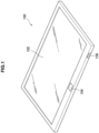
FIG. 1 is an explanatory diagram showing an appearance example of aPC 100 according to the first embodiment of the present disclosure. With reference toFIG. 1 , the appearance example of thePC 100 according to the first embodiment of the present disclosure will be explained. - The
PC 100 according to the first embodiment of the present disclosure achieves an always-on always-connected (AOAC) environment in which thePC 100 can constantly connect to a network and can instantly turn on and off a power supply. ThePC 100 according to the first embodiment of the present disclosure achieves the always-on always-connected (AOAC) environment by using iSCT. The following description will be given on a premise that thePC 100 achieving the AOAC environment using iSCT has a state (SO-iSCT) running with low power consumption in addition to a sleeping mode set by Advanced Configuration and Power Interface (ACPI). - As shown in
FIG. 1 , the PC10 according to the first embodiment of the present disclosure is a so-called tablet type apparatus including a touchscreen in a display.FIG 1 shows thePC 100 including adisplay unit 102, amain button 104, and apower button 106. - The
display unit 102 includes a display for displaying a letter, an image, a movie, and other information. For example, thedisplay unit 102 may include a liquid crystal display, or an organic EL display. In addition, thedisplay unit 102 includes a touchscreen having a touchpad on a display screen. ThePC 100 receives input operation performed by a user by causing the user to touch thedisplay unit 102 with a finger, a stylus, or the like. - The
main button 104 is a button for turning on thedisplay unit 102, or for causing a certain menu screen to be displayed on thedisplay unit 102. For example, when the user presses themain button 104 in a state where thedisplay unit 102 is off, thePC 100 shifts into a running state (S0), causes thedisplay unit 102 to turn on, and displays a lock screen or a menu screen on thedisplay unit 102. The lock screen is a screen for preventing the PC100 from operating improperly by an unintended touch to the touchscreen. The menu screen is a screen for causing the user to execute an application. - The
power button 106 is a button for turning on and off thePC 100. When the user keeps pressing (so called long press) thepower button 106 for a certain time period, thePC 100 performs processing such as turning on the power so as to shift into a running state (S0), or turning off the power. - For example, when the user presses the
power button 106 in a state where thedisplay unit 106 is off, thePC 100 causes thedisplay unit 102 to turn on, and displays the lock screen or the menu screen on thedisplay unit 102. As an another example, when the user presses thepower button 106 in a state where thedisplay unit 102 is on and displays a screen, thePC 100 causes thedisplay unit 102 to turn off. A function of themain button 104 and a function of thepower button 106 differ in that thePC 100 does not cause thedisplay unit 102 to turn off even if the user presses themain button 104 in the state where thedisplay unit 102 is on and displaying a screen. - Peripheral equipment such as a keyboard, a touchpad, and a mouse may be connected to the
PC 100 while the peripheral equipment is not shown inFIG. 1 . For example, such peripheral equipment is connected to thePC 100 through a Universal Serial Bus (USB). - In the case where the user puts the
PC 100 into the sleep state (S3), iSCT periodically (for example, every 15 minutes during a day, and every 2 hours during a night) causes thePC 100 to return to a state (SO-iSCT) running with low power consumption, to run only for a short time, and to receive an e-mail and update data in a state where thedisplay unit 102 is off without the user knowing about such operation. Note that, the S3 state is an example of a first mode according the embodiment of the present disclosure, and the S0-iSCT state is an example of a second mode according the embodiment of the present disclosure. - To put the
PC 100 into the sleep state (S3), for example, the user keeps thePC 100 unused for a while, or the user presses thepower button 106 so as to turn off thedisplay unit 102. Next, after receiving the e-mail or updating the data, the PC100 shifts into the sleep state (S3) again. As described above, even if thePC 100 is in the sleep state (S3), thePC 100 can get new information by periodically shifting from the sleep state (S3) to the S0-iSCT state. - In a state where a sleep mode is S3, the
PC 100 can maintain the S3 state even if the user unintendedly performs input operation on an input device such as the touchscreen. However, in a state where a sleep mode is S0-iSCT, for a system of a PC such as an OS or BIOS, there is no difference from a running state (S0). When a touchscreen is touched in the state where the sleep mode is S0-iSCT, a screen turns on in response to the touch and the tablet type PC such as thePC 100 shifts into the running state (S0). Accordingly, when the AOAC environment is tried to be achieved in such tablet type PC by using iSCT, the tablet type PC may unexpectedly shift from S0-iSCT to a running state (S3) in a bag for example, and heating and unnecessary consumption of battery may occur in association with the running. - Even in the S0-iSCT state, the
PC 100 does not turn on thedisplay unit 102 only by touching themain button 104 or thepower button 106. However, it is highly possible that thedisplay unit 102 constituting a large part of a surface area of thePC 100 is touched without the user knowing about the touch. Accordingly, a shift into the running state (S0) by touching thedisplay unit 102 that the user does not intend has to be avoided. - A similar phenomenon may occur not only by touching the touchscreen, but also by touching the peripheral equipment which may be connected in a wireless or wired manner, such as a keyboard and a touchpad. That is, when the peripheral equipment which may be connected in a wireless or wired manner, such as the keyboard or the touchpad, is touched in the state where the sleep mode is S0-iSCT, the screen turns on in response to the touch and the state of the
PC 100 shifts into the running state (S0). - In a traditional PC, the keyboard and the touchpad are often controlled by systems such as the Basic Input/Output System (BIOS), an embedded controller (EC), and a keyboard controller (KBC). In this case, the systems stop giving a notification to an OSs of equipment such as the keyboard and touchpad in the S0-iSCT state, and accordingly control can be performed. However, in a case where the equipment such as the keyboard and the touchpad are connected through the USB, the system side can know the shift into S0-iSCT, but it is difficult for the system side to perform control so as to disable a notification to the OSs of equipment such as the keyboard and touchpad.
- Accordingly, when sifting into the S0-iSCT state, the
PC 100 according to the embodiment of the present disclosure gives a notification indicating that the state of thePC 100 has shifted into the S0-iSCT state, to a program referred to as a utility program that operates on the OS executed by thePC 100. Subsequently, the utility program, which received a notification indicating that the state of thePC 100 has shifted into the S0-iSCT state, performs control so as to disable input to the input device such as the touchscreen, the keyboard, and the touchpad. According to such operation, thePC 100 according to the embodiment can prevent shifting into the running state (S0) even if input that the user does not intend is performed on the touchscreen, the keyboard, the touchpad, and the like in the S0-iSCT state. - With reference to
FIG. 1 , the appearance example of thePC 100 according to the first embodiment of the present disclosure has been explained. Next, a configuration example of thePC 100 according to the first embodiment of the present disclosure will be explained. -
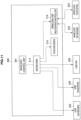
FIG. 2 is an explanatory diagram showing a configuration example of thePC 100 according to the first embodiment of the present disclosure. In the following, with reference toFIG. 2 , the configuration example of thePC 100 according to the first embodiment of the present disclosure will be explained. - As shown in
FIG. 2 , thePC 100 according to the first embodiment of the present disclosure includes aniSCT control module 112, BIOS/EC/KBC 114, a devicecontrol utility program 116, atouchscreen 118, and a wireless USB receiver/controller 119. - The
touchscreen 118 is a device that is provided on thedisplay unit 102 and in which the display screen and the touchpad are integrated. The user of thePC 100 can operate thePC 100 by touching thetouchscreen 118 with the finger, the stylus, or the like, or by approximating the finger, the stylus, or the like to thetouchscreen 118. - In addition,
FIG. 2 further shows that thePC 100 connects with aUSB keyboard 112, aUSB touchpad 124, and a USB human interface device (HID) 126 other than the keyboard and the touchpad. - The
USB keyboard 112, theUSB touchpad 124, and the USB HID 126 are each a device connected with thePC 100 through a USB, and are each an input device for causing the user to perform certain input operation to thePC 100. - The
iSCT control module 112 is a module for controlling whether thePC 100 shifts from the sleep state (S3) to the S0-iSCT state in the case where thePC 100 is in the sleep state (S3). When theiSCT control module 112 receives, from the BIOS/EC/KBC 114, a notification that thePC 100 is in the sleep state (S3), theiSCT control module 112 periodically (for example, every 15 minutes during a day, and every 2 hours during a night) determines whether a condition for a shift into the S0-iSCT state is satisfied. - For example, a precondition for the shift into the S0-iSCT state is whether the
PC 100 has connected to a network such as the Internet or the wireless LAN. In a case where thePC 100 has not connected to the network such as the Internet or the wireless LAN, thePC 100 does not shift into the S0-iSCT state because thePC 100 cannot acquire information through the network. On the other hand, in a case where thePC 100 has satisfied the precondition for the shift into the S0-iSCT state, theiSCT control module 112 notifies the BIOS/EC/KBC 114 to periodically shift into the S0-iSCT state. Note that, theiSCT control module 112 does not give the notification to the BIOS/EC/KBC 114 in a case where thePC 100 has not connected to the network such as the Internet or the wireless LAN and has not satisfied the condition for the shift into S0-iSCT state. - The BIOS/EC/
KBC 114 is a system for controlling hardware of thePC 100. The BIOS/EC/KBC 114 changes an inner power-supply state according to states of the sleep mode of thePC 100. - The
PC 100 according to the embodiment has the S0-iSCT state as the sleep mode. When receiving the notification to shift into the S0-iSCT state from theiSCT control module 112, the BIOS/EC/KBC 114 periodically shifts into the S0-iSCT state. Subsequently, when the BIOS/EC/KBC 114 shifted into the S0-iSCT state, the BIOS/EC/KBC 114 gives, to the devicecontrol utility program 116, a notification that the BIOS/EC/KBC 114 shifted into the S0-iSCT state. - The device
control utility program 116 is software operating on an OS executed by thePC 100. According to a setting by the user, the devicecontrol utility program 116 switches enabling and disabling of an input device embedded in or connected with thePC 100. Alternatively, the devicecontrol utility program 116 switches enabling and disabling of input from the input device embedded in or connected with thePC 100 in a wireless or wired manner, according to a state of the sleep mode of thePC 100 that is switched by the BIOS/EC/KBC 114. Here, in an input device that is a target for the devicecontrol utility program 116 to switch enabling and disabling of input, the sleep mode is shifted from S0-iSCT state to the S0 state when the operation input is received. - Specifically, when the BIOS/EC/
KBC 114 gives, to the devicecontrol utility program 116, a notification that the sleep mode has shifted into the S0-iSCT state, the devicecontrol utility program 116 disables input from atouchscreen 118, aUSB keyboard 122, aUSB touchpad 124, and a USB HID 126 that are managed by the devicecontrol utility program 116. For example, the devicecontrol utility program 116 disables the input from thetouchscreen 118, theUSB keyboard 122, theUSB touchpad 124, and the USB HID 126 through an application programming interface (API) of the OS operating in thePC 100. - As a method for disabling input from the
touchscreen 118, theUSB keyboard 122, theUSB touchpad 124, and the USB HID 126, the devicecontrol utility program 116 may ignore input events performed on such input devices, or may cause the events themselves not to occur by stopping power supply to such input devices. - As described above, when the sleep mode has shifted into the S0-iSCT state, input from the
touchscreen 118, theUSB keyboard 122, theUSB touchpad 124, and the USB HID 126 are disabled. Accordingly, thePC 100 can prevent the sleep mode from shifting into the S0 state when input operation that the user does not intend is performed on thetouchscreen 118, theUSB keyboard 122, theUSB touchpad 124, and the USB HID 126 in the case where the sleep mode is in the S0-iSCT state. - Note that, the
PC 100 may include the wireless USB receiver/controller 119 for exchanging signals between various kinds of devices in a wireless manner. For example, as shown inFIG. 2 , the wireless USB receiver/controller 119 exchanges signals with awireless keyboard 132 and awireless touchpad 134 in a wireless manner. In a case where thePC 100 includes the wireless USB receiver/controller 119 and the sleep mode is S0-iSCT state, the sleep mode shifts into the S0 state if thewireless keyboard 132 and thewireless touchpad 134 are not prevented from being input. - When the device
control utility program 116 receives, from the BIOS/EC/KBC 114, a notification that the sleep mode has shifted into the S0-iSCT state in the case where thePC 100 includes the wireless USB receiver/controller 119, the devicecontrol utility program 116 disables input from the input device connected with the wireless USB receiver/controller 119. By disabling the input from the input device connected with the wireless USB receiver/controller 119, thePC 100 can prevent a shift into the S0 state in the case of S0-iSCT state due to input operation to thewireless keyboard 132 or thewireless touchpad 134 that the user does not intend. - The device
control utility program 116 may decide an input device whose input is to be disabled according to the user setting in the case where the sleep mode is the S0-iSCT state. For example, the devicecontrol utility program 116 may decide that only the wireless USB receiver/controller 119 is not to be disabled according to the user setting in the case where the sleep mode is the S0-iSCT state. - Since the
PC 100 according to the first embodiment of the present disclosure includes the configuration shown inFIG. 2 , thePC 100 can prevent the sleep mode from shifting into the S0 state in response to input operation that the user does not intend in the state where the sleep mode is S0-iSCT state. Accordingly, thePC 100 according to the first embodiment of the present disclosure can prevent an unexpected shift into a running state in a bag, and can prevent heating and unnecessary consumption of battery from occurring in association with the running. - With reference to
FIG. 2 , the configuration example of thePC 100 according to the first embodiment of the present disclosure has been explained. Next, an operation example of thePC 100 according to the first embodiment of the present disclosure will be explained. -
FIG. 3 is a flowchart showing an operation example of thePC 100 according to the first embodiment of the present disclosure.FIG. 3 shows an operation example of thePC 100 in a case of enabling and disabling the input from the input device according to the sleep mode of thePC 100. In the following, with reference toFIG. 3 , the operation example of thePC 100 according to the first embodiment of the present disclosure will be explained. - The flowchart in
FIG. 3 shows processing executed on a premise that the sleep mode of thePC 100 is the sleep state (S3). As described above, to put the sleep mode of thePC 100 into the sleep state (S3), for example, the user keeps thePC 100 unused for a while, or the user presses thepower button 106 so as to turn off thedisplay unit 102. - When the
iSCT control module 112 receives, from the BIOS/EC/KBC 114, a notification that thePC 100 is in the sleep state (S3), theiSCT control module 112 periodically (for example, every 15 minutes during a day, and every 2 hours during a night) confirms whether the condition for a shift into the S0-iSCT state is satisfied (Step S101). Subsequently, if the condition for a shift into the S0-iSCT state is satisfied, theiSCT control module 112 notifies the BIOS/EC/KBC 114 to periodically shift into the S0-iSCT state. When the BIOS/EC/KBC 114 receives, from theiSCT control module 112, the notification to shift into the S0-iSCT state, the BIOS/EC/KBC 114 shifts the sleep mode into the S0-iSCT state. - Next, when the sleep mode has shifted into the S0-iSCT state, the BIOS/EC/
KBC 114 gives, to the devicecontrol utility program 116, a notification that the sleep mode has shifted into the S0-iSCT state (Step S102). When the devicecontrol utility program 116 receives, from the BIOS/EC/KBC 114, a notification that the sleep mode has shifted into the S0-iSCT state, the devicecontrol utility program 116 disables a device (in this embodiment, thetouchscreen 118, the wireless USB receiver/controller 119, theUSB keyboard 122, theUSB touchpad 124, or the USB HID 126) that shifts from the S0-iSCT state to the S0 state in response to input operation among devices controlled by the device control utility program 116 (Step S103). - The device
control utility program 116 disables input from the device that shifts from the S0-iSCT state to the S0 state in response to input operation among devices controlled by the devicecontrol utility program 116. Accordingly, the sleep mode is prevented from shifting from the S0-iSCT state to the S0 state in response to input operation to the device that the user does not intend. - The sleep mode has shifted into the S0-iSCT state, update processing of information such as receiving an e-mail has been executed, the update processing has been completed, and then the
PC 100 shifts the sleep mode into the sleep state (S3) again (Step S104). After shifting into the S3 state, the BIOS/EC/KBC 114 notifies the devicecontrol utility program 116 of shifting into the S3 state (Step S105). - When the device
control utility program 116 receives, from the BIOS/EC/KBC 114, a notification that the sleep mode has shifted into the S3 state, the devicecontrol utility program 116 enables the device that has been disabled in Step S103 (Step S106). In a case where the sleep mode is the S3 state, thePC 100 maintains the S3 state even if input operation that the user does not intend is performed on the enabled device. - Since the
PC 100 according to the first embodiment of the present disclosure executes the operation shown inFIG. 3 , thePC 100 can prevent the sleep mode from shifting into the S0 state in response to input operation that the user does not intend in the case where the sleep mode is S0-iSCT state. Accordingly, thePC 100 according to the first embodiment of the present disclosure can prevent an unexpected shift into a running state in a bag, and can prevent heating and unnecessary consumption of battery from occurring in association with the running. - If the user wants to use the
PC 100 in a case where the sleep mode is S0-iSCT state, the user may press themain button 104 or thepower button 106, for example. When the user has pressed themain button 104 or thepower button 106, thePC 100 shifts the sleep mode from the S0-iSCT state to the S0 state and becomes the running state. That is, in Step S103, input from themain button 104 and thepower button 106 are not disabled. This is because, if such buttons are disabled, the user cannot explicitly tell thePC 100 that the user has a will to use thePC 100 in the case where the sleep mode is the S0-iSCT state. - The above processing is an example of a case where the
PC 100 is the tablet type apparatus. However, the example according to embodiments of the present disclosure is not limited thereto. For example, there is a laptop type apparatus having at least two forms: a form in which a lid is closed in a state where the embedded display is not exposed; and a form in which the lid is closed in a state where the embedded display is exposed. Such PC may be referred to as a convertible PC, a transformable PC, or the like. In the following descriptions, the form in which the lid is closed in the state where the embedded display is not exposed may be referred to as a "clamshell mode", and the form in which the lid is closed in a state where the embedded display is exposed may be referred to as a "tablet mode" with regard to such apparatus having at least two forms. -
FIGS. 4 to 6 are explanatory diagrams showing appearance examples of aPC 100 according to the first embodiment of the present disclosure.FIG. 4 is an appearance example of a state where a lid of thePC 100 is opened,FIG. 5 is an appearance example of a state where thePC 100 is in the clamshell mode, andFIG. 6 is an appearance example of a state where thePC 100 is in the tablet mode. - When the
PC 100 adopts such forms, thePC 100 may determine whether input from the device is to be disabled in accordance with how the lid is closed. That is, in the case of the clamshell mode as shown inFIG. 5 , touch that the user does not intend is not performed on the touchscreen. However, in the case of the tablet mode as shown inFIG. 6 , the touch that the user does not intend may be performed. Accordingly, only in the case of the tablet mode as shown inFIG. 6 , thePC 100 disables the input from the device when the sleep mode is the S0-iSCT state. -
FIG. 7 is a flowchart showing an operation example of thePC 100 according to a modification of the first embodiment of the present disclosure.FIG. 7 shows an operation example of thePC 100 when input from the device is to be enabled or disabled depending on the sleep mode of thePC 100 or the form of thePC 100. In the following, with reference toFIG. 7 , the operation example of thePC 100 according to the modification of the first embodiment of the present disclosure will be explained. - The flowchart in
FIG. 7 shows processing executed on a premise that the sleep mode of thePC 100 is the sleep state (S3) in the same way as the flowchart shown inFIG. 3 . In addition, the flowchart inFIG. 7 shows processing executed on a premise that the user closed the lid of thePC 100 and the sleep mode of thePC 100 is the sleep state (S3). - In the same way as the processing shown in
FIG. 3 , theiSCT control module 112 periodically confirms whether the condition for a shift into the S0-iSCT state is satisfied (Step S111). When the BIOS/EC/KBC 114 receives, from theiSCT control module 112, the notification to shift into the S0-iSCT state, the BIOS/EC/KBC 114 shifts the sleep mode into the S0-iSCT state. - Next, when the sleep mode has shifted into the S0-iSCT state, the BIOS/EC/
KBC 114 gives, to the devicecontrol utility program 116, a notification that the sleep mode has shifted into the S0-iSCT state (Step S112). When the devicecontrol utility program 116 receives, from the BIOS/EC/KBC 114, a notification that the sleep mode has shifted into the S0-iSCT state, the devicecontrol utility program 116 first determines whether the form of thePC 100 is the tablet mode (Step S113). For example, the BIOS/EC/KBC 114 may know whether the form of thePC 100 is the tablet mode. Accordingly, the devicecontrol utility program 116 may acquire information about the form of thePC 100 from the BIOS/EC/KBC 114. - In the case where the form of the
PC 100 is the tablet mode (Yes in Step S113), the devicecontrol utility program 116 disables a device (in this embodiment, thetouchscreen 118, wireless USB receiver/controller 119, theUSB keyboard 122, theUSB touchpad 124, or the USB HID 126) that shifts from the S0-iSCT state to the S0 state in response to input operation among devices controlled by the device control utility program 116 (Step S114). On the other hand, in a case where the form of thePC 100 is not the tablet mode (No in Step S113), the devicecontrol utility program 116 does not disable the device. - The sleep mode has shifted into the S0-iSCT state, update processing of information such as receiving an e-mail has been executed, the update processing has been completed, and then the
PC 100 shifts the sleep mode into the sleep state (S3) again (Step S115). After shifting into the S3 state, the BIOS/EC/KBC 114 notifies the devicecontrol utility program 116 of shifting into the S3 state (Step S116). When the devicecontrol utility program 116 receives, from the BIOS/EC/KBC 114, a notification that the sleep mode has shifted into the S3 state, the devicecontrol utility program 116 enables the device that has been disabled in Step S103 (Step S117). - Since the
PC 100 according to the modification of the first embodiment of the present disclosure executes the operation shown inFIG. 7 , thePC 100 can prevent the sleep mode from shifting into the S0 state in response to input operation that the user does not intend in the case where the sleep mode is S0-iSCT state and the form is the tablet mode. Accordingly, thePC 100 according to the modification of the first embodiment of the present disclosure can prevent an unexpected shift into a running state in a bag, and can prevent heating and unnecessary consumption of battery from occurring in association with the running in the case where the form is the tablet mode. - In the above-described first embodiment of the present disclosure, the device
control utility program 116 operating on the OS executed in thePC 100 disables the input from the input device in accordance with the state of the sleep mode. However, embodiments of the present disclosure are not limited thereto. For example, the OS or the devicecontrol utility program 116 operating on the OS disables input from the input device by using a command prepared for each input device. - There are PCs which can realize a specification of Connected Standby. Connected Standby is a state where a state of a PC is S0, a processor and a communication module is in operation, and a display is off. In the Connected Standby state, the PC is led by an OS and sets each device in a sleep state referred to as Runtime D3 (RTD3). By setting the devices in the RTD3 state, input operation from each device is disabled in the Connected Standby state.
- Accordingly, in the case where the
PC 100 can realize Connected Standby, the BIOS/EC/KBC 114 or the devicecontrol utility program 116 may set each input device in the above-described RTD3 state when the sleep mode is the S0-iSCT state. After the sleep mode becomes the S0-iSCT state, by setting each input device in the RTD3 state, thePC 100 can prevent the sleep mode from shifting into the S0 state in response to input operation that the user does not intend. - Next, a second embodiment of the present disclosure will be explained. In the first embodiment, when the sleep mode had become the S0-iSCT state, by disabling input from the input device, the
PC 100 can prevent the sleep mode from shifting into the S0 state in response to input operation that the user does not intend. - On the other hand, as described above, when the display is turned off, a state of the
PC 100 becomes the sleep state (S3), and the input device is disabled in the sleep state. Alternatively, in the iSCT, a video standby state that is prepared for normal PCs remains. The Video Standby state is a state where systems are in operation (S0) even if the screen is turned off. - The Video Standby state is a running state (S0) for the systems, and a touchscreen and other input devices are in a valid state. Accordingly the user can turn on the screen by touching the touchscreen in the Video Standby state.
- In the above-described first embodiment, when the sleep mode becomes the S0-iSCT state, input from the input device is disabled. Accordingly, the user cannot turn on the screen by touching the touchscreen in the S0-iSCT state. On the other hand, the user can turn on the screen by touching the touchscreen in the Video Standby state (S3 state, but not S0-iSCT state). Accordingly, the states where the screen is off are the same, but the behaviors are different in accordance with inner states when the user touches the touchscreens.
- Accordingly, the second embodiment of the present disclosure proposes a configuration or operation that prevents the sleep mode from shifting into the S0 state due to input operation that the user does not intend, or a configuration or operation that prevents the screen from turning on and thereby prevents unnecessary consumption of battery from occurring, by disabling input from an input device in the case where the screen is off.
-
FIG. 8 is an explanatory diagram showing a configuration example of aPC 200 according to the second embodiment of the present disclosure. In the following, with reference toFIG. 8 , the configuration example of thePC 200 according to the second embodiment of the present disclosure will be explained. - The
PC 200 shown inFIG. 8 is a tablet type apparatus similar to thePC 100 according to the first embodiment of the present disclosure, and has an appearance similar to the form shown inFIG. 1 . As shown inFIG. 8 , thePC 200 according to the second embodiment of the present disclosure includes abacklight control unit 201, BIOS/EC/KBC 214, a devicecontrol utility program 216, atouchscreen 218, and a wireless USB receiver/controller 219. In the present embodiment, thetouchscreen 218 is a combination of a liquid crystal display screen and a touchpad. - The
backlight control unit 201 controls backlight lighting that irradiates from a back face of thetouchscreen 218. Thebacklight control unit 201 transmits a backlight signal to the BIOS/EC/KBC 214 when backlight radiates from the back face of thetouchscreen 218. That is, in a case where the screen is displayed, thebacklight control unit 201 transmits the backlight signal to the BIOS/EC/KBC 214. In a case where the screen is not displayed, thebacklight control unit 201 does not transmit the backlight signal to the BIOS/EC/KBC 214. - The BIOS/EC/
KBC 214 is a system for controlling hardware of thePC 200. In this embodiment, the BIOS/EC/KBC 214 gives, to the devicecontrol utility program 216, a notification that the backlight has not radiated in a case where thebacklight control unit 201 has not transmitted the backlight signal. - The device
control utility program 216 is software operating on an OS of thePC 200. According to a setting by the user, the devicecontrol utility program 216 switches enabling and disabling of an input device embedded in or connected with thePC 200. Alternatively, the devicecontrol utility program 216 switches enabling and disabling of the input device embedded in or connected with thePC 100, according to presence or absence of backlight irradiation to thetouchscreen 218. Here, in an input device that is a target for the devicecontrol utility program 116 to switch enabling and disabling, thebacklight control unit 201 starts irradiating thetouchscreen 218 with the backlight when the operation input is received. - Specifically, when the BIOS/EC/
KBC 114 gives, to the backlightcontrol utility program 216, a notification that thebacklight control unit 201 has stopped irradiating thetouchscreen 218 with the backlight, the devicecontrol utility program 216 disables atouchscreen 218, aUSB keyboard 222, aUSB touchpad 224, and a USB HID 226 that are managed by the devicecontrol utility program 216. For example, the devicecontrol utility program 216 disables thetouchscreen 218, theUSB keyboard 222, theUSB touchpad 224, and the USB HID 226 through an API of the OS operating in thePC 200. By disabling thetouchscreen 218, theUSB keyboard 222, theUSB touchpad 224, and the USB HID 226, thePC 200 can prevent the screen from turning on in response to input operation to such input devices that the user does not intend. - In a way similar to the first embodiment, in the case where the
PC 200 includes the wireless USB receiver/controller 219, the devicecontrol utility program 216 may disable the wireless USB receiver/controller 219. By disabling the wireless USB receiver/controller 219, thePC 200 can prevent the screen from turning on in response to input operation to thewireless keyboard 232 or thewireless touchpad 234 that the user does not intend. - Since the
PC 200 according to the second embodiment of the present disclosure includes the configuration shown inFIG. 8 , thePC 200 can prevent the screen from turning on in response to input operation that the user does not intend in the state where the screen is in the off state. Accordingly, thePC 200 according to the second embodiment of the present disclosure can prevent the screen from turning on, and can prevent heating and unnecessary consumption of battery from occurring in association with the screen lighting. - With reference to
FIG. 8 , the configuration example of thePC 200 according to the second embodiment of the present disclosure has been explained. Next, an operation example of thePC 200 according to the second embodiment of the present disclosure will be explained. -
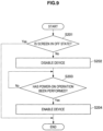
FIG. 9 is a flowchart showing an operation example of thePC 200 according to the second embodiment of the present disclosure.FIG. 9 shows an operation example of thePC 200 in a case of enabling and disabling the input from the input device according to the lighting state of the screen of thePC 200. In the following, with reference toFIG. 9 , the operation example of thePC 200 according to the second embodiment of the present disclosure will be explained. - As described above, the BIOS/EC/
KBC 214 gives, to the devicecontrol utility program 216, a notification that the backlight has not radiated in a case where thebacklight control unit 201 has not transmitted the backlight signal. Accordingly, the devicecontrol utility program 216 determines whether or not the screen is in the off state on the basis of whether BIOS/EC/KBC 214 sends a notification that backlight has not radiated (Step S201). - In a case where the screen is in the off state (Yes in Step S201), the device
control utility program 216 disables a device (in this embodiment, thetouchscreen 218, the wireless USB receiver/controller 119, theUSB keyboard 222, theUSB touchpad 224, or the USB HID 226) whose screen is turned on in response to input operation among devices controlled by the device control utility program 216 (Step S202). - Subsequently, the
PC 200 determines whether the user has performed certain power-on operation on the PC 200 (Step S203). For example, the power-on operation of thePC 200 is operation for pressing themain button 104 or apower button 106 shown in the first embodiment. - The
PC 200 waits until the user performed the certain power-on operation on the PC 200 (No in Step S203). When the user performed the certain power-on operation on the PC 200 (Yes in Step S203), the BIOS/EC/KBC 214 detects the certain power-on operation and gives, to the devicecontrol utility program 216, a notification that the power-on operation was performed. The devicecontrol utility program 216 receives the notification, and enables the device that was disabled in the Step S202 (Step S204). - Note that, if the screen is not in the off state (No in Step S201), a series of processing in
FIG. 9 are skipped. - Since the
PC 200 according to the second embodiment of the present disclosure executes the operation shown inFIG. 9 , thePC 200 can prevent the screen from turning on in response to input operation that the user does not intend in the state where the screen is in the off state. Accordingly, thePC 200 according to the second embodiment of the present disclosure can prevent the screen from turning on, and can prevent heating and unnecessary consumption of battery from occurring in association with the screen lighting. - Note that, in the second embodiment, input from the input device is enabled or disabled in accordance with whether the backlight signal is transmitted. However, input from the input device may also be enabled or disabled in accordance with whether the screen is off in a case where the
PC 200 includes a self-light-emitting-type display that is not lit by the backlight. In the case where thePC 200 includes the self-light-emitting-type display, the BIOS/EC/KBC 214 can detect whether the display is lighting by sending a certain signal to the BIOS/EC/KBC 214 when the screen turns on. - In the second embodiment, input from the input device is enabled or disabled in accordance with whether the screen is off. However, the
PC 200 according to the second embodiment may have the AOAC environment according to the iSCT. That is, thePC 200 according to the second embodiment may periodically become the S0-iSCT state and perform processing for updating information. Needless to say, even if the sleep mode is the S0-iSCT state, the screen is off. Accordingly, thePC 200 according to the second embodiment can disable input from the input device and prevent the screen from turning on. - In the above embodiments, the device
control utility program PC KBC -
FIGS. 10 and11 are explanatory diagrams showing configuration examples of thePCs FIG 10 is a modification of thePC 100, andFIG. 11 is a modification of thePC 200. - As shown in
FIGS. 10 and11 , it is also possible for the BIOS/EC/KBC KBC KBC KBC - As shown in
FIGS. 10 and11 , the BIOS/EC/KBC - In addition, as another example of enabling or disabling an input device, the BIOS/EC/
KBC KBC - The above described processing may be executed, for example, by using the hardware configuration of an information processing apparatus illustrated in
FIG. 12 . In other words, the processing may be realized by using a computer program to control the hardware illustrated inFIG. 12 . Note that the format of this hardware is arbitrary, and encompasses personal computers, mobile phones, portable information terminals such as PHS devices and PDAs, game consoles, contact or contactless IC chips, contact or contactless IC cards, and various information appliances, for example. Note that PHS above is an abbreviation for Personal Handy-phone System, while PDA above is an abbreviation for personal digital assistant. - As illustrated in
FIG. 12 , the hardware primarily includes aCPU 902,ROM 904,RAM 906, ahost bus 908, and abridge 910. The hardware additionally includes anexternal bus 912, aninterface 914, aninput unit 916, anoutput unit 918, astorage unit 920, adrive 922, aconnection port 924, and acommunication unit 926. Note that CPU above is an abbreviation for central processing unit, while ROM above is an abbreviation for read-only memory, and RAM above is an abbreviation for random access memory. - The
CPU 902 functions as a computational processing device or control device, for example, and controls all or part of the operation of each structural element on the basis of various programs recorded in theROM 904, theRAM 906, thestorage unit 920, or aremovable recording medium 928. TheROM 904 is a way of storing information such as programs loaded by theCPU 902 and data used in computations. TheRAM 906 transiently or persistently stores information such as programs loaded by theCPU 902, and various parameters that change as appropriate when executing such programs, for example. - These structural elements are interconnected via a
host bus 908 capable of high-speed data transmission, for example. Meanwhile, thehost bus 908 is connected via thebridge 910 to anexternal bus 912 having comparatively low-speed data transmission, for example. Devices such as a mouse, keyboard, touch panel, buttons, switches, and levers may be used as theinput unit 916, for example. Additionally, a remote control (hereinafter, remote) capable of using infrared or other electromagnetic waves to transmit control signals may be used as theinput unit 916 in some cases. - The
output unit 918 includes a device capable of visually or aurally reporting acquired information to a user, and may be a display device such as a CRT, LCD, PDP, or ELD, an audio output device such as one or more speakers or headphones, a printer, a mobile phone, or a fax machine, for example. Note that CRT above is an abbreviation for cathode ray tube, while LCD above is an abbreviation for liquid crystal display, PDP above is an abbreviation for plasma display panel, and ELD above is an abbreviation for electroluminescent display. - The
storage unit 920 is a device that stores various data. Devices such as a hard disk drive or other magnetic storage device, a semiconductor storage device, an optical storage device, or a magneto-optical storage device may be used as thestorage unit 920, for example. Note that HDD above is an abbreviation for hard disk drive. - The
drive 922 is a device that reads out information recorded onto aremovable recording medium 928 such as a magnetic disk, an optical disc, a magneto-optical disc, or semiconductor memory, for example, and may also write information to theremovable recording medium 928. Theremovable recording medium 928 is an instance of DVD media, Blu-ray media, HD DVD media, or various semiconductor storage media, for example. Obviously, theremovable recording medium 928 may also be an IC card mounted with a contactless IC chip, or other electronic device, for example. Note that IC above is an abbreviation for integrated circuit. - The
connection port 924 is a port that connects to an externally connecteddevice 930, such as a USB port, an IEEE 1394 port, a SCSI port, an RS-232C port, or an optical audio terminal, for example. The externally connecteddevice 930 may be a printer, a portable music player, a digital camera, a digital video camera, or an IC recorder, for example. Note that USB above is an abbreviation for Universal Serial Bus, while SCSI above is an abbreviation for Small Computer System Interface. - The
communication unit 926 is a communication device that connects to anetwork 932, and may be a communication card for wired or wireless LAN, Bluetooth (registered trademark), or WUSB, an optical communication router, an ADSL router, or a device for contact or contactless communication, for example. Also, thenetwork 932 connected to thecommunication unit 926 is a network connected in a wired or wireless manner, and may be the Internet, a home LAN, infrared communication, visible light communication, broadcasting, or satellite communication, for example. Note that LAN above is an abbreviation for local area network, while WUSB above is an abbreviation for Wireless USB, and ADSL above is an abbreviation for asymmetric digital subscriber line. - As described above, according to the embodiments of the present disclosure, the
PCs PC PC - Accordingly, since the
PC - It may not be necessary to chronologically execute respective steps in the processing, which is executed by each apparatus of this specification, in the order described in the sequence diagrams or the flow charts. For example, the respective steps in the processing which is executed by each apparatus may be processed in the order different from the order described in the flow charts, and may also be processed in parallel.
- Further, a computer program for causing hardware, such as a CPU, ROM and RAM built into each apparatus to exhibit functions the same as each of the configuration of each apparatus can be created. Further, a storage medium on which this computer program is recorded can also be provided. Moreover, series of processes can also be realized by hardware by configuring the respective function blocks illustrated in the function block diagrams as hardware.
- It should be understood by those skilled in the art that various modifications, combinations, subcombinations and alterations may occur depending on design requirements and other factors insofar as they are within the scope of the appended claims or the equivalents thereof.
- In addition, the advantageous effects described in the specification are merely explanatory or illustrative, and are not limited. In other words, the technology according to the present disclosure can exert other advantageous effects that are clear to those skilled in the art from the description of the specification, in addition to or instead of the advantageous effects described above.
Claims (11)
- An information processing apparatus (100, 200) comprising:a display (102);an input device (118, 122, 124, 126, 132, 134);a mode control unit (112, 201) configured to perform control at least so as to periodically confirm whether a condition for a switch from a first mode that causes the information processing apparatus (100, 200) to be operated in a first state at a first voltage level into a second mode that causes the information processing apparatus (100, 200) to be operated in a second state at a second voltage level higher than the first voltage level is satisfied, wherein the second state is a state running with low power consumption in comparison to the power consumption of a running state and/or with the display (102) being in an off state, and to periodically switch from the first mode into the second mode if the condition is satisfied; andan operation control unit (116, 216) configured to disable certain input operation on the input device (118, 122, 124, 126, 132, 134) performed by a user upon receiving a notification that the first state has shifted into the second state if the information processing apparatus (100, 200) operates in the second state, after the mode control unit (112, 201) switches the mode from the first mode to the second mode, and to prevent the information processing apparatus (100, 200) from switching into the running state and/or the display (102) from turning on if the certain input operation is performed by the user.
- The information processing apparatus (100, 200) according to claim 1,
wherein the first mode is a mode, in which the information processing apparatus (100, 200) is operating in a sleep state as the first state. - The information processing apparatus (100, 200) according to claim 1,
wherein, in the case where the information processing apparatus (100, 200) is operating in the state where the display (102) is off, the operation control unit (116, 216) disables the certain input operation if the information processing apparatus (100, 200) is not in the first mode. - The information processing apparatus (100, 200) according to claim 1,
wherein the operation control unit (116, 216) is configured to perform control in a manner that predetermined input operation not to be disabled exists even if the information processing apparatus (100, 200) operates in the second state or the display (102) is off. - The information processing apparatus (100, 200) according to claim 4,
wherein the predetermined input operation not to be disabled is input operation to a power button (106). - The information processing apparatus (100, 200) according to claim 1,
wherein the mode control unit (112, 201) is configured to cause communication processing with external equipment to be executed when causing the information processing apparatus (100, 200) to be operated in the second mode. - The information processing apparatus (100, 200) according to claim 1,
wherein the operation control unit (116, 216) is configured to stop power supply to a device on which input operation is performed when certain input operation performed by a user is disabled. - The information processing apparatus (100, 200) according to claim 1,
wherein the operation control unit (116, 216) is configured to disable input from a device on which input operation is performed when certain input operation performed by a user is disabled. - The information processing apparatus (100, 200) according to claim 1,
wherein the operation control unit (116, 216) is configured to determine an exposure state of a display (102) and then determine whether the information processing apparatus (100, 200) operates in the second state or the display (102) is off. - The information processing apparatus (100, 200) according to claim 9,
wherein, in a state where the display (102) is exposed, the operation control unit (116, 216) is configured to determines whether the information processing apparatus (100, 200) operates in the second state or the display (102) is off. - A power control method comprising:performing control at least so as to periodically confirm whether a condition for a switch from a first mode that causes an information processing apparatus (100, 200) to be operated in a first state at a first voltage level into a second mode that causes the information processing apparatus (100, 200) to be operated in a second state at a second voltage level higher than the first voltage level is satisfied, wherein the second state is a state running with low power consumption in comparison to the power consumption of a running state and/or with the display (102) being in an off state, and to periodically switch from the first mode into the second mode if the condition is satisfied; anddisabling certain input operation on an input device (118, 122, 124, 126, 132, 134) performed by a user upon receiving a notification that the first state has shifted into the second state if the information processing apparatus (100, 200) operates in the second state, after the mode control unit (112, 201) switches the mode from the first mode to the second mode; andpreventing the information processing apparatus (100, 200) from switching into the running state and/or the display (102) from turning on if the certain input operation is performed by the user.
Applications Claiming Priority (1)
| Application Number | Priority Date | Filing Date | Title |
|---|---|---|---|
| JP2013175222A JP6155971B2 (en) | 2013-08-27 | 2013-08-27 | Information processing apparatus, information processing system, and power control method |
Publications (3)
| Publication Number | Publication Date |
|---|---|
| EP2857929A2 EP2857929A2 (en) | 2015-04-08 |
| EP2857929A3 EP2857929A3 (en) | 2015-11-04 |
| EP2857929B1 true EP2857929B1 (en) | 2023-08-02 |
Family
ID=51485435
Family Applications (1)
| Application Number | Title | Priority Date | Filing Date |
|---|---|---|---|
| EP14181252.9A Active EP2857929B1 (en) | 2013-08-27 | 2014-08-18 | Information processing apparatus, information processing system, and power control method |
Country Status (4)
| Country | Link |
|---|---|
| US (1) | US9519332B2 (en) |
| EP (1) | EP2857929B1 (en) |
| JP (1) | JP6155971B2 (en) |
| CN (1) | CN104423535B (en) |
Families Citing this family (9)
| Publication number | Priority date | Publication date | Assignee | Title |
|---|---|---|---|---|
| KR102089512B1 (en) * | 2013-11-05 | 2020-03-16 | 한국전자통신연구원 | Network Available Terminal's Sleep State Providing System and the Method |
| JP6569320B2 (en) * | 2015-06-19 | 2019-09-04 | セイコーエプソン株式会社 | Electronic device and method for controlling electronic device |
| US20170097673A1 (en) * | 2015-10-01 | 2017-04-06 | Lenovo Enterprise Solutions (Singapore) Pte. Ltd. | Computer system and method providing both main and auxiliary power over a single power bus |
| US10521107B2 (en) | 2016-09-24 | 2019-12-31 | Apple Inc. | Devices, methods, and graphical user interfaces for selecting and interacting with different device modes |
| US20190212798A1 (en) * | 2016-09-29 | 2019-07-11 | Hewlett-Packard Development Company, L.P. | Disable power button |
| JP6804939B2 (en) | 2016-11-02 | 2020-12-23 | ソニーモバイルコミュニケーションズ株式会社 | Information processing device and information processing method |
| DK201870335A1 (en) | 2018-05-07 | 2019-12-04 | Apple Inc. | Devices, methods, and graphical user interfaces for proactive management of notifications |
| AU2020233622B2 (en) * | 2020-05-11 | 2022-03-10 | Apple Inc. | System, method and user interface for supporting scheduled mode changes on electronic devices |
| US20220365640A1 (en) | 2021-05-12 | 2022-11-17 | Apple Inc. | Devices, Methods, and Graphical User Interfaces for Adjusting the Provision of Notifications |
Citations (1)
| Publication number | Priority date | Publication date | Assignee | Title |
|---|---|---|---|---|
| US20030105983A1 (en) * | 2001-12-03 | 2003-06-05 | Brakmo Lawrence Sivert | Power reduction in computing devices using micro-sleep intervals |
Family Cites Families (15)
| Publication number | Priority date | Publication date | Assignee | Title |
|---|---|---|---|---|
| JP4190294B2 (en) * | 2003-01-14 | 2008-12-03 | シャープ株式会社 | Electronic equipment |
| JP4235884B2 (en) | 2003-02-10 | 2009-03-11 | ソニー株式会社 | Noise reduction apparatus, noise reduction method, and program |
| KR101136036B1 (en) * | 2003-12-24 | 2012-04-18 | 삼성전자주식회사 | Processor system and method for reducing power consumption in idle mode |
| US20060200684A1 (en) * | 2005-03-01 | 2006-09-07 | Vasudev Bibikar | Power mode change voltage control in computerized system |
| JP2007288296A (en) * | 2006-04-13 | 2007-11-01 | Mitsubishi Electric Corp | Mobile terminal |
| KR20080073872A (en) * | 2007-02-07 | 2008-08-12 | 엘지전자 주식회사 | Mobile communication terminal with touch screen and method of inputting information using same |
| JP4364259B2 (en) * | 2007-05-17 | 2009-11-11 | 京セラ株式会社 | Mobile device |
| US20090166098A1 (en) * | 2007-12-31 | 2009-07-02 | Apple Inc. | Non-visual control of multi-touch device |
| US8195220B2 (en) * | 2008-02-01 | 2012-06-05 | Lg Electronics Inc. | User interface for mobile devices |
| US8806231B2 (en) * | 2009-12-22 | 2014-08-12 | Intel Corporation | Operating system independent network event handling |
| US20110300915A1 (en) * | 2010-06-08 | 2011-12-08 | Nokia Corporation | Method, apparatus and computer program product for enabling partial functionality of a mobile terminal |
| JP5804498B2 (en) * | 2011-08-22 | 2015-11-04 | 埼玉日本電気株式会社 | State control device, state control method and program |
| JP5890186B2 (en) * | 2012-01-27 | 2016-03-22 | 京セラ株式会社 | Portable terminal, lock state control program, and lock state control method |
| JP2013161255A (en) * | 2012-02-03 | 2013-08-19 | Sony Corp | Information terminal device and information processing method |
| CN102833830B (en) * | 2012-08-20 | 2016-12-21 | 广东欧珀移动通信有限公司 | One wakes up mobile intelligent terminal method and mobile intelligent terminal up |
-
2013
- 2013-08-27 JP JP2013175222A patent/JP6155971B2/en active Active
-
2014
- 2014-08-18 EP EP14181252.9A patent/EP2857929B1/en active Active
- 2014-08-20 US US14/463,996 patent/US9519332B2/en active Active
- 2014-08-20 CN CN201410411994.6A patent/CN104423535B/en active Active
Patent Citations (1)
| Publication number | Priority date | Publication date | Assignee | Title |
|---|---|---|---|---|
| US20030105983A1 (en) * | 2001-12-03 | 2003-06-05 | Brakmo Lawrence Sivert | Power reduction in computing devices using micro-sleep intervals |
Also Published As
| Publication number | Publication date |
|---|---|
| US20150067365A1 (en) | 2015-03-05 |
| JP2015045902A (en) | 2015-03-12 |
| CN104423535A (en) | 2015-03-18 |
| CN104423535B (en) | 2019-03-19 |
| JP6155971B2 (en) | 2017-07-05 |
| EP2857929A2 (en) | 2015-04-08 |
| US9519332B2 (en) | 2016-12-13 |
| EP2857929A3 (en) | 2015-11-04 |
Similar Documents
| Publication | Publication Date | Title |
|---|---|---|
| EP2857929B1 (en) | Information processing apparatus, information processing system, and power control method | |
| US20210271306A1 (en) | Apparatus and method for waking up a processor | |
| US9740268B2 (en) | Intelligent management for an electronic device | |
| US10007316B2 (en) | State control method and apparatus and portable terminal | |
| US8230243B2 (en) | Information processing apparatus | |
| US11467650B2 (en) | Selecting a low power state in an electronic device | |
| US9110687B2 (en) | Information processing apparatus and operation control method | |
| KR20150033505A (en) | Method for performing a power save mode on an electronic device and the electronic device therefor | |
| US20150370383A1 (en) | Electronic apparatus and sensor control method | |
| WO2022001813A1 (en) | Application program control method and apparatus, and electronic device | |
| CN104252203B (en) | Electronic device, method for controlling electronic device, and program | |
| US20130318381A1 (en) | Electronic apparatus and start method for electronic apparatus | |
| JP2014071733A (en) | Information processor and operation control method | |
| JP5112542B1 (en) | Information processing apparatus and control method of information processing apparatus | |
| JP2018092658A (en) | Built-in controller chip, system, and device | |
| JP2006155051A (en) | Device for processing information and control method thereof | |
| KR102278475B1 (en) | Electronic apparatus and controlling method thereof | |
| JP2008257749A (en) | Apparatus and method for controlling system | |
| JP5085714B2 (en) | Information processing apparatus and control method thereof | |
| JP2012118891A (en) | Reduction method for power consumption of computer, and computer | |
| CN106126201B (en) | Terminal charging method and device | |
| JP2007272366A (en) | Electronic appliance and operation control method | |
| JP2010044793A (en) | Information processor | |
| TWI389542B (en) | Portable electronic apparatus capable of simulating as a wireless communication product and method thereof | |
| JP2013162655A (en) | Electronic device, electronic device controlling method, electronic device controlling program, and electronic system |
Legal Events
| Date | Code | Title | Description |
|---|---|---|---|
| PUAI | Public reference made under article 153(3) epc to a published international application that has entered the european phase |
Free format text: ORIGINAL CODE: 0009012 |
|
| 17P | Request for examination filed |
Effective date: 20140818 |
|
| AK | Designated contracting states |
Kind code of ref document: A2 Designated state(s): AL AT BE BG CH CY CZ DE DK EE ES FI FR GB GR HR HU IE IS IT LI LT LU LV MC MK MT NL NO PL PT RO RS SE SI SK SM TR |
|
| AX | Request for extension of the european patent |
Extension state: BA ME |
|
| PUAL | Search report despatched |
Free format text: ORIGINAL CODE: 0009013 |
|
| AK | Designated contracting states |
Kind code of ref document: A3 Designated state(s): AL AT BE BG CH CY CZ DE DK EE ES FI FR GB GR HR HU IE IS IT LI LT LU LV MC MK MT NL NO PL PT RO RS SE SI SK SM TR |
|
| AX | Request for extension of the european patent |
Extension state: BA ME |
|
| RIC1 | Information provided on ipc code assigned before grant |
Ipc: G06F 1/32 20060101AFI20151001BHEP Ipc: G06F 3/041 20060101ALI20151001BHEP Ipc: H04W 52/02 20090101ALI20151001BHEP |
|
| R17P | Request for examination filed (corrected) |
Effective date: 20160504 |
|
| RBV | Designated contracting states (corrected) |
Designated state(s): AL AT BE BG CH CY CZ DE DK EE ES FI FR GB GR HR HU IE IS IT LI LT LU LV MC MK MT NL NO PL PT RO RS SE SI SK SM TR |
|
| STAA | Information on the status of an ep patent application or granted ep patent |
Free format text: STATUS: REQUEST FOR EXAMINATION WAS MADE |
|
| STAA | Information on the status of an ep patent application or granted ep patent |
Free format text: STATUS: EXAMINATION IS IN PROGRESS |
|
| 17Q | First examination report despatched |
Effective date: 20180518 |
|
| STAA | Information on the status of an ep patent application or granted ep patent |
Free format text: STATUS: EXAMINATION IS IN PROGRESS |
|
| RAP3 | Party data changed (applicant data changed or rights of an application transferred) |
Owner name: SONY GROUP CORPORATION |
|
| STAA | Information on the status of an ep patent application or granted ep patent |
Free format text: STATUS: EXAMINATION IS IN PROGRESS |
|
| REG | Reference to a national code |
Ref document number: 602014087815 Country of ref document: DE Ref country code: DE Ref legal event code: R079 Free format text: PREVIOUS MAIN CLASS: G06F0001320000 Ipc: H04W0052020000 |
|
| GRAP | Despatch of communication of intention to grant a patent |
Free format text: ORIGINAL CODE: EPIDOSNIGR1 |
|
| STAA | Information on the status of an ep patent application or granted ep patent |
Free format text: STATUS: GRANT OF PATENT IS INTENDED |
|
| INTG | Intention to grant announced |
Effective date: 20230224 |
|
| RIC1 | Information provided on ipc code assigned before grant |
Ipc: G06F 1/3234 20190101ALI20230210BHEP Ipc: G06F 1/3231 20190101ALI20230210BHEP Ipc: G06F 1/3287 20190101ALI20230210BHEP Ipc: H04W 52/02 20090101AFI20230210BHEP |
|
| GRAS | Grant fee paid |
Free format text: ORIGINAL CODE: EPIDOSNIGR3 |
|
| GRAA | (expected) grant |
Free format text: ORIGINAL CODE: 0009210 |
|
| STAA | Information on the status of an ep patent application or granted ep patent |
Free format text: STATUS: THE PATENT HAS BEEN GRANTED |
|
| AK | Designated contracting states |
Kind code of ref document: B1 Designated state(s): AL AT BE BG CH CY CZ DE DK EE ES FI FR GB GR HR HU IE IS IT LI LT LU LV MC MK MT NL NO PL PT RO RS SE SI SK SM TR |
|
| REG | Reference to a national code |
Ref country code: GB Ref legal event code: FG4D |
|
| REG | Reference to a national code |
Ref country code: CH Ref legal event code: EP |
|
| REG | Reference to a national code |
Ref country code: DE Ref legal event code: R096 Ref document number: 602014087815 Country of ref document: DE |
|
| REG | Reference to a national code |
Ref country code: IE Ref legal event code: FG4D |
|
| PGFP | Annual fee paid to national office [announced via postgrant information from national office to epo] |
Ref country code: NL Payment date: 20230907 Year of fee payment: 10 |
|
| REG | Reference to a national code |
Ref country code: LT Ref legal event code: MG9D |
|
| PGFP | Annual fee paid to national office [announced via postgrant information from national office to epo] |
Ref country code: DE Payment date: 20230822 Year of fee payment: 10 |
|
| REG | Reference to a national code |
Ref country code: NL Ref legal event code: MP Effective date: 20230802 |
|
| REG | Reference to a national code |
Ref country code: AT Ref legal event code: MK05 Ref document number: 1596254 Country of ref document: AT Kind code of ref document: T Effective date: 20230802 |
|
| PG25 | Lapsed in a contracting state [announced via postgrant information from national office to epo] |
Ref country code: GR Free format text: LAPSE BECAUSE OF FAILURE TO SUBMIT A TRANSLATION OF THE DESCRIPTION OR TO PAY THE FEE WITHIN THE PRESCRIBED TIME-LIMIT Effective date: 20231103 |
|
| PG25 | Lapsed in a contracting state [announced via postgrant information from national office to epo] |
Ref country code: IS Free format text: LAPSE BECAUSE OF FAILURE TO SUBMIT A TRANSLATION OF THE DESCRIPTION OR TO PAY THE FEE WITHIN THE PRESCRIBED TIME-LIMIT Effective date: 20231202 |
|
| PG25 | Lapsed in a contracting state [announced via postgrant information from national office to epo] |
Ref country code: SE Free format text: LAPSE BECAUSE OF FAILURE TO SUBMIT A TRANSLATION OF THE DESCRIPTION OR TO PAY THE FEE WITHIN THE PRESCRIBED TIME-LIMIT Effective date: 20230802 Ref country code: RS Free format text: LAPSE BECAUSE OF FAILURE TO SUBMIT A TRANSLATION OF THE DESCRIPTION OR TO PAY THE FEE WITHIN THE PRESCRIBED TIME-LIMIT Effective date: 20230802 Ref country code: PT Free format text: LAPSE BECAUSE OF FAILURE TO SUBMIT A TRANSLATION OF THE DESCRIPTION OR TO PAY THE FEE WITHIN THE PRESCRIBED TIME-LIMIT Effective date: 20231204 Ref country code: NO Free format text: LAPSE BECAUSE OF FAILURE TO SUBMIT A TRANSLATION OF THE DESCRIPTION OR TO PAY THE FEE WITHIN THE PRESCRIBED TIME-LIMIT Effective date: 20231102 Ref country code: NL Free format text: LAPSE BECAUSE OF FAILURE TO SUBMIT A TRANSLATION OF THE DESCRIPTION OR TO PAY THE FEE WITHIN THE PRESCRIBED TIME-LIMIT Effective date: 20230802 Ref country code: LV Free format text: LAPSE BECAUSE OF FAILURE TO SUBMIT A TRANSLATION OF THE DESCRIPTION OR TO PAY THE FEE WITHIN THE PRESCRIBED TIME-LIMIT Effective date: 20230802 Ref country code: LT Free format text: LAPSE BECAUSE OF FAILURE TO SUBMIT A TRANSLATION OF THE DESCRIPTION OR TO PAY THE FEE WITHIN THE PRESCRIBED TIME-LIMIT Effective date: 20230802 Ref country code: IS Free format text: LAPSE BECAUSE OF FAILURE TO SUBMIT A TRANSLATION OF THE DESCRIPTION OR TO PAY THE FEE WITHIN THE PRESCRIBED TIME-LIMIT Effective date: 20231202 Ref country code: HR Free format text: LAPSE BECAUSE OF FAILURE TO SUBMIT A TRANSLATION OF THE DESCRIPTION OR TO PAY THE FEE WITHIN THE PRESCRIBED TIME-LIMIT Effective date: 20230802 Ref country code: GR Free format text: LAPSE BECAUSE OF FAILURE TO SUBMIT A TRANSLATION OF THE DESCRIPTION OR TO PAY THE FEE WITHIN THE PRESCRIBED TIME-LIMIT Effective date: 20231103 Ref country code: FI Free format text: LAPSE BECAUSE OF FAILURE TO SUBMIT A TRANSLATION OF THE DESCRIPTION OR TO PAY THE FEE WITHIN THE PRESCRIBED TIME-LIMIT Effective date: 20230802 Ref country code: AT Free format text: LAPSE BECAUSE OF FAILURE TO SUBMIT A TRANSLATION OF THE DESCRIPTION OR TO PAY THE FEE WITHIN THE PRESCRIBED TIME-LIMIT Effective date: 20230802 |
|
| PG25 | Lapsed in a contracting state [announced via postgrant information from national office to epo] |
Ref country code: PL Free format text: LAPSE BECAUSE OF FAILURE TO SUBMIT A TRANSLATION OF THE DESCRIPTION OR TO PAY THE FEE WITHIN THE PRESCRIBED TIME-LIMIT Effective date: 20230802 |
|
| REG | Reference to a national code |
Ref country code: CH Ref legal event code: PL |