EP2857868A1 - Wing releasing system for a navigation control device - Google Patents
Wing releasing system for a navigation control device Download PDFInfo
- Publication number
- EP2857868A1 EP2857868A1 EP13306384.2A EP13306384A EP2857868A1 EP 2857868 A1 EP2857868 A1 EP 2857868A1 EP 13306384 A EP13306384 A EP 13306384A EP 2857868 A1 EP2857868 A1 EP 2857868A1
- Authority
- EP
- European Patent Office
- Prior art keywords
- wing
- releasing
- wings
- decision circuit
- control device
- Prior art date
- Legal status (The legal status is an assumption and is not a legal conclusion. Google has not performed a legal analysis and makes no representation as to the accuracy of the status listed.)
- Granted
Links
- 238000000034 method Methods 0.000 claims description 18
- 238000012545 processing Methods 0.000 claims description 5
- 230000006870 function Effects 0.000 description 15
- 238000004891 communication Methods 0.000 description 6
- 230000008569 process Effects 0.000 description 5
- 241001481166 Nautilus Species 0.000 description 4
- 238000013459 approach Methods 0.000 description 4
- 230000008859 change Effects 0.000 description 4
- 238000012360 testing method Methods 0.000 description 3
- XLYOFNOQVPJJNP-UHFFFAOYSA-N water Substances O XLYOFNOQVPJJNP-UHFFFAOYSA-N 0.000 description 3
- 230000006978 adaptation Effects 0.000 description 2
- 230000006399 behavior Effects 0.000 description 2
- 230000008901 benefit Effects 0.000 description 2
- 230000007797 corrosion Effects 0.000 description 2
- 238000005260 corrosion Methods 0.000 description 2
- 238000001514 detection method Methods 0.000 description 2
- 230000000694 effects Effects 0.000 description 2
- 238000012544 monitoring process Methods 0.000 description 2
- 230000004913 activation Effects 0.000 description 1
- 230000032683 aging Effects 0.000 description 1
- 230000005540 biological transmission Effects 0.000 description 1
- 238000007654 immersion Methods 0.000 description 1
- 238000012423 maintenance Methods 0.000 description 1
- 239000000463 material Substances 0.000 description 1
- 230000007246 mechanism Effects 0.000 description 1
- 230000003287 optical effect Effects 0.000 description 1
- 238000011084 recovery Methods 0.000 description 1
- 230000000717 retained effect Effects 0.000 description 1
- 239000013535 sea water Substances 0.000 description 1
- 239000013049 sediment Substances 0.000 description 1
- 230000035882 stress Effects 0.000 description 1
Images

Classifications
-
- B—PERFORMING OPERATIONS; TRANSPORTING
- B63—SHIPS OR OTHER WATERBORNE VESSELS; RELATED EQUIPMENT
- B63B—SHIPS OR OTHER WATERBORNE VESSELS; EQUIPMENT FOR SHIPPING
- B63B21/00—Tying-up; Shifting, towing, or pushing equipment; Anchoring
- B63B21/56—Towing or pushing equipment
- B63B21/66—Equipment specially adapted for towing underwater objects or vessels, e.g. fairings for tow-cables
-
- G—PHYSICS
- G01—MEASURING; TESTING
- G01V—GEOPHYSICS; GRAVITATIONAL MEASUREMENTS; DETECTING MASSES OR OBJECTS; TAGS
- G01V1/00—Seismology; Seismic or acoustic prospecting or detecting
- G01V1/38—Seismology; Seismic or acoustic prospecting or detecting specially adapted for water-covered areas
- G01V1/3817—Positioning of seismic devices
- G01V1/3826—Positioning of seismic devices dynamic steering, e.g. by paravanes or birds
Definitions
- the field of the invention is the acquisition of geophysics data. It deals with the equipments required in order to study the seabed and its sediment layers properties.
- the invention relates to a wing releasing system for a navigation control device (commonly referred to as "bird”), such a navigation control device being adapted for controlling the depth and/or the lateral position of a towed acoustic linear antenna (commonly referred to as "streamer").
- a navigation control device commonly referred to as "bird”
- streamer a navigation control device
- the invention can be applied notably to the oil prospecting industry using seismic method (sea oil survey), but can be of interest for any other field which requires a system performing geophysics data acquisition in a marine environment.
- the operations of acquiring seismic data on site conventionally use networks of seismic sensors, like accelerometers, geophones or hydrophones.
- the hydrophones are distributed along cables in order to form linear acoustic antennas normally (also referred to as “streamers” or “seismic streamers”).
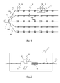
- the network of seismic streamers 20a to 20e is towed by a seismic vessel 21.
- the hydrophones are referenced 16 in figure 2 , which illustrates in detail the block referenced C in figure 1 (i.e. a portion of the streamer referenced 20a).
- the seismic method is based on an analysis of reflected seismic waves.
- one or more submerged seismic sources are activated in order to propagate omnidirectional seismic wave trains.
- the pressure wave generated by the seismic source passes through the column of water and insonifies the different layers of the seabed.
- the reflected seismic waves i.e. reflected acoustic signals
- These acoustic signals are processed and retransmitted by telemetry from the seismic streamers to the operator station situated on the seismic vessel, where the processing of the raw data is carried out (in an alternative solution, the seismic acoustic signals are stored for a later processing).
- each bird 10 comprises a body 11 equipped with motorized pivoting wings 12 (or more generally means of mechanical moving) making it possible to modify the position of the streamers laterally between them (this is referred to a horizontal driving) and drive the streamers in immersion (this is referred to a vertical driving).
- Seismic marine acquisition is usually performed close to the coast where fishermen have installed fishing nets. Some areas over the world are full of thousands of nets, which are not identified. Despite fishermen are requested to remove the nets and chase boats try to detect presence of nets, they are still many nets at sea, when the seismic vessel is working. Seismic streamers towed by vessel can easily catch fishing nets. The slanted shape of the streamers, in the current acquisition programs, increases the risk for a streamer to catch nets that float below the surface because the water column is more important. Since streamers are smooth, nets (or any inconvenient foreign objects) are sliding down the streamer, until they get caught by a prominent device which most often is a bird.
- BIL Beird In Line
- Connects that supply power and data communication. See for example the following patent documents: US7933163 , US7206254 , US2009/0204274 and US7080607 .
- These "BIL” comprise a body, in series with the streamer, and wings, which are interdependent with the body.
- These birds comprise, for each wing, a passive mechanical fuse which breaks to prevent the transmission of excessive mechanical stress to the bird and hence to the streamer. If a fishing net is caught by a wing, only this wing is released.
- BIP Back In Parallel
- Power is supplied by internal battery and data communication is done through contactless magnetic coils. If a fishing net is caught by a wing, quick latches are acting as passive mechanical fuse to release the entire bird (body and wings). A rope fixed to the streamer allows the bird to remain attached to the streamer when released.
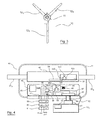
- Birds of a third type can be seen as a hybrid solution since they comprise (see bird 10 of figure 3 ): at least one module (not shown), placed in series along the streamer (not shown), and a body (tubular frame element) 11, freely rotating around the at least one module and placed in parallel with the streamer.
- Three wings are attached to the body 11: two motorized upper wings 12a, 12b and a lower non-motorized wing (keel) 12c.
- keel non-motorized wing
- the use of a passive mechanical fuse (for a wing in the case of birds of the first or third type, or for the whole bird in the case of birds of the second type) is not a reliable solution since the passive mechanical fuse can be seized or neutralized depending how fishing nets (or any inconvenient foreign objects) are attached to the bird and/or to the streamer. This results in a non-activation of the passive mechanical fuse when required.
- the passive mechanical fuse (for the entire bird or a given wing) can be activated when not required (e.g. in case of heavy seas, the entire bird or the given wing may be released due to a severe load on the wing caused by the swell, when the entire bird or the given wing should remain attached to the streamer).
- the birds of the third type (“Nautilus®” solution) become unstable when a fishing net is caught in the wings. They roll over the stability domain and twist around the streamer. They finally twist also the streamer on which they are fixed, until damaging the streamer.
- the invention in at least one embodiment, is aimed especially at overcoming these different drawbacks of the prior art.
- a particular embodiment of the invention proposes a wing releasing system for releasing at least one wing of a set of wing or wings of a navigation control device, the navigation control device being adapted for controlling the depth and/or the lateral position of a towed acoustic linear antenna and comprising a body to which is attached the set of wing or wings.
- the wing releasing system comprises:
- the general principle is to take an active approach rather than the passive approach of the prior art.
- the prior art solutions use a passive mechanical fuse to release the entire bird (birds of the second type) or only a wing (birds of the first type), or do not provide any mechanism for releasing the bird or a wing (birds of the third type).
- the proposed solution is an active approach since it uses an actuator which is activated if a release request signal is generated (i.e. if the releasing decision circuit detects that a foreign object (e.g. a fishing net) has been caught by at least one wing.
- the wing releasing system can be easily modified to adapt to any environment (e.g. by a simple software update of the releasing decision circuit), unlike a constraining mechanical change in case a passive mechanical fuse is used.
- said releasing decision circuit comprises:
- the releasing decision circuit takes a decision (i.e. generates the release request signal which is then used as an input by the actuator) as a function of at least one measure, this decision is more precise and appropriate than the release obtained in the prior art with a passive mechanical fuse.
- This decision can be taken automatically (e.g. when the releasing decision circuit is comprised in the navigation control device or in a management system on board a vessel) or through a man-machine interface (e.g. when the releasing decision circuit is comprised in a management system on board a vessel).
- said means for deciding comprise signal processing means, with programmable settings.
- said at least one measure belongs to the group comprising:
- the releasing decision circuit is comprised in the navigation control device.
- the whole wing releasing system is comprised in the navigation control device, and the latter can operate independently (the releasing decision is taken locally, in the navigation control device).
- the navigation control device comprises a module placed in series along the towed acoustic linear antenna, said body freely rotates around said module.
- Said releasing decision circuit is comprised in said body, in said module or in said at least one wing of the set of wing or wings.
- This case is for example an adaptation of the existing birds of the third type (e.g. Sercel's product called "Nautilus®").
- the body of the navigation control device comprises a module placed in series along the towed acoustic linear antenna.
- Said releasing decision circuit is comprised in said module or in said at least one wing of the set of wing or wings.
- This case is for example an adaptation of the existing birds of the first type ("Bird In Line").
- said releasing decision circuit is comprised in a management system on board a vessel, and the wing releasing system further comprises:
- the wing releasing system is distributed: the actuator is comprised in the navigation control device and the releasing decision circuit is on board the vessel.
- the navigation control device does not operate independently since the releasing decision is taken on board the vessel.
- the wing releasing system comprises a main battery, for powering the releasing decision circuit and the actuator.
- said releasing decision circuit, said actuator and said main battery are contained in a watertight housing comprising a watertight connector, and said watertight connector is connected to said releasing decision circuit, said actuator and said main battery, and comprises means for cooperation with:
- the watertight connector is easy to use during transportation (with the shunting dongle), during acquisition phases (with the passing dongle) and when the bird is brought on-board (for connection to the bench).
- the releasing decision circuit comprises an embedded memory to log events and record load cases.
- Another particular embodiment of the invention proposes a method for releasing at least one wing of a set of wing or wings of a navigation control device adapted for controlling the depth and/or the lateral position of a towed acoustic linear antenna and comprising a body to which is attached the set of wing or wings, the method comprising the following steps:
- the bird 40 comprises:
- the wing releasing system is a wing releasing device 42, which is inside the body 11 and used to release the lower wing 12c from the body 11, when it detects that a foreign object (e.g. a fishing net) is caught by the lower wing 12c.
- the wing releasing device is inside the lower wing 12c, or any wing to release.
- the wing releasing device is inside the inline module 41.
- the wing releasing device 42 comprises a small size watertight housing (composed of a base 43a and a lid 43b) which contains:
- the watertight connector 47 is watertight even in open face. It is connected to the electronics 44, the actuator 50, the main battery 45, the auxiliary battery 46 and the ground 56, and comprises means for cooperation with a shunting dongle 59, a passing dongle 60 or a bench 61.
- the shunting dongle 59 is screwed to the watertight connector 47, in order to desactivate (shortcut) the actuator 50 and disconnect (open) the main battery 45 from the electronics 44.
- the passing dongle 60 is screwed to the watertight connector 47, in order to activate the actuator 50 and connect the main battery 45 to the electronics 44.
- the watertight connector 47 ic connected to the bench 61, in order to desactivate the actuator 50, charge the main battery 45 (via a power line) and exchange data with the electronics 44 (via a serial port) (e.g. for downloading new firmware and retrieve data).
- the electronics 44 i.e. the "releasing decision circuit"
- the electronics 44 receives from the mechanical load sensor 49 a measure of the mechanical load F.
- the electronics 44 compares this measure F with a threshold Fmax. In case of negative answer (i.e.
- step 73 in which the counter N is set to 0, and then to step 74, which is a waiting step of 30 seconds, before returning to setp 71.
- step 75 in which the counter N is incremented by one
- step 76 in which the electronics 44 compares N with a threshold (e.g. equal to 5). If N ⁇ 5, then the process goes to step 77, which is a waiting step of 1 second, before returning to setp 71. Otherwise, the process goes to step 78, in which the release request signal is generated (it is used to order the actuator 50 to release the lower wing 12c and associated shaft 5).
- the electronics 44 (“releasing decision circuit”) generates automatically a release request signal (used to activate an actuator 50), as a function of a load signal generated by a load sensor 49.
- the electronics 44 can generate the release request signal as a function of other types of measures, provided that these measures concern a parameter representative or related to a load applied on a wing.
- measures this list is not exhaustive:
- the releasing decision circuit when the releasing decision circuit is comprised in a management system on board a vessel (see figure 8 described below), it can generate the release request signal either automatically or not.
- an operator on board the vessel is provided with the measures (which are e.g. displayed on a screen), decides whether a foreign object is caught by the wing, and provides his decision (through a man-machine interface) to the releasing decision circuit which then generates the release request signal (if the operator has decided that a foreign object is caught).
- the magnetic sensor 54 e.g. magnetometer
- the magnetic sensor 54 measures the whole magnetic field created by the environment, including: Earth magnetic field, magnetic field generated by the electronics 55, wires inside the inline module 41 and magnetic field generated by the magnet 52 situated inside the lower wing 12c.
- the electronics 55 carries out several functions (each of these functions can be seen like a specific circuit of an operation managing system):
- the electronics 55 receives (from the electronics 44, via the radiocommunication means 48) a release information signal indicating the release of the lower wing 12c.
- the degraded operating mode is defined as follows, when one of the two motorized upper wings 12a, 12b is released: the driving circuit (electronics 55) acts on the other of the two motorized upper wings to control the depth of the streamer 20a and to control an angle of attack at 0°, relative to a flow of water.
- electronics 44 (comprised in the wing releasing device 42) and electronics 55 (comprised in the inline module 41) each comprise a read-only memory (ROM) 440, 550, a random access memory (RAM) 441, 551 and a processor 442, 552.
- the read-only memory 440, 550 is a non-transitory computer-readable carrier medium. It stores executable program code instructions, which are executed by the processor 442, 552 in order to enable implementation of the functions described above (see also figure 7 for the function executed by the electronics 44 comprised in the wing releasing device 42).
- the aforementioned program code instructions are transferred from the read-only memory 440, 550 to the random access memory 441, 551 so as to be executed by the processor 442, 552.
- the random access memory 441, 551 likewise includes registers for storing the variables and parameters required for this execution.
- the proposed solution is not limited to the release of the lower wing 12c, and can be implemented with one or several wings (among the set of wings of the birds).
- the proposed solution is not limited to the release of wing or wings of birds of the third type (e.g. Sercel's product called "Nautilus®").
- it can also be implemented with birds of the first type ("Bird In Line"), i.e. when the body of the bird comprises a module placed in series along the streamer, and in that case the releasing decision circuit is comprised in the module or in one or several of the wings.
- the bird 40' of the second embodiment differs from the bird 40 of the first embodiment (see figure 4 ) in that the electronics (referenced 44' in figure 8 ) still provides the release request signal to the actuator 50 (for releasing the lower wing 12c), but does not generate it. In other words, the electronics 44' does not perform the function of the releasing decision circuit.
- the releasing decision circuit 83 is comprised in a management system 81, on board the vessel 21.
- the wing releasing system comprises:
- the releasing decision circuit 83 comprised in the management system on board the vessel, can generate the release request signal either automatically (as the electronics 44 in the embodiment of figure 4 ) or not.
- an operator on board the vessel is provided with the measures (which are e.g. displayed on a screen), decides whether a foreign object is caught by the wing, and provides his decision (through a man-machine interface) to the releasing decision circuit 83 which then generates the release request signal (if the operator has decided that a foreign object is caught).
Landscapes
- Life Sciences & Earth Sciences (AREA)
- Physics & Mathematics (AREA)
- Engineering & Computer Science (AREA)
- Geophysics (AREA)
- Acoustics & Sound (AREA)
- Environmental & Geological Engineering (AREA)
- Geology (AREA)
- Remote Sensing (AREA)
- General Life Sciences & Earth Sciences (AREA)
- General Physics & Mathematics (AREA)
- Oceanography (AREA)
- Combustion & Propulsion (AREA)
- Chemical & Material Sciences (AREA)
- Mechanical Engineering (AREA)
- Ocean & Marine Engineering (AREA)
- Catching Or Destruction (AREA)
- Geophysics And Detection Of Objects (AREA)
- Control Of Position, Course, Altitude, Or Attitude Of Moving Bodies (AREA)
- Navigation (AREA)
- Position Fixing By Use Of Radio Waves (AREA)
Abstract
Description
- The field of the invention is the acquisition of geophysics data. It deals with the equipments required in order to study the seabed and its sediment layers properties.
- More specifically, the invention relates to a wing releasing system for a navigation control device (commonly referred to as "bird"), such a navigation control device being adapted for controlling the depth and/or the lateral position of a towed acoustic linear antenna (commonly referred to as "streamer").
- The invention can be applied notably to the oil prospecting industry using seismic method (sea oil survey), but can be of interest for any other field which requires a system performing geophysics data acquisition in a marine environment.
- It is sought more particularly here below in this document to describe problems existing in the field of seismic data acquisition for oil prospecting industry. The invention of course is not limited to this particular field of application but is of interest for any technique that has to cope with closely related or similar issues and problems.
- The operations of acquiring seismic data on site conventionally use networks of seismic sensors, like accelerometers, geophones or hydrophones. We consider below the context of seismic data acquisition in a marine environment, in which the seismic sensors are hydrophones. The hydrophones are distributed along cables in order to form linear acoustic antennas normally (also referred to as "streamers" or "seismic streamers"). As shown in
figure 1 , the network ofseismic streamers 20a to 20e is towed by aseismic vessel 21. The hydrophones are referenced 16 infigure 2 , which illustrates in detail the block referenced C infigure 1 (i.e. a portion of the streamer referenced 20a). - The seismic method is based on an analysis of reflected seismic waves. Thus, to collect geophysical data in a marine environment, one or more submerged seismic sources are activated in order to propagate omnidirectional seismic wave trains. The pressure wave generated by the seismic source passes through the column of water and insonifies the different layers of the seabed. The reflected seismic waves (i.e. reflected acoustic signals) are then detected by the hydrophones distributed over the length of the seismic streamers. These acoustic signals are processed and retransmitted by telemetry from the seismic streamers to the operator station situated on the seismic vessel, where the processing of the raw data is carried out (in an alternative solution, the seismic acoustic signals are stored for a later processing).
- During seismic surveys, it is important to precisely locate the streamers in particular for:
- monitoring the position of the hydrophones (distributed along the seismic streamers) in order to obtain a satisfactory precision of the image of the seabed in the exploration zone;
- detecting the movements of the streamers with respect to one another (the streamers are often subjected to various external natural constrains of variable magnitude, such as the wind, waves, currents); and
- monitoring the navigation of streamers, in particular in a situation of bypassing an obstacle (such as an oil barge).
- Control of the positions of streamers lies in the implementation of navigation control devices (also referred to as "birds") (white squares referenced 10 in
figure 1 ). They are installed at regular intervals (every 300 meters for example) along the seismic streamers. The function of those birds is to guide the streamers between themselves. In other words, the birds are used to control the depth as well as the lateral position of the streamers. For this purpose, and as illustrated infigure 2 , eachbird 10 comprises abody 11 equipped with motorized pivoting wings 12 (or more generally means of mechanical moving) making it possible to modify the position of the streamers laterally between them (this is referred to a horizontal driving) and drive the streamers in immersion (this is referred to a vertical driving). - Seismic marine acquisition is usually performed close to the coast where fishermen have installed fishing nets. Some areas over the world are full of thousands of nets, which are not identified. Despite fishermen are requested to remove the nets and chase boats try to detect presence of nets, they are still many nets at sea, when the seismic vessel is working. Seismic streamers towed by vessel can easily catch fishing nets. The slanted shape of the streamers, in the current acquisition programs, increases the risk for a streamer to catch nets that float below the surface because the water column is more important. Since streamers are smooth, nets (or any inconvenient foreign objects) are sliding down the streamer, until they get caught by a prominent device which most often is a bird.
- When a fishing net is caught by a bird:
- drag increase on the streamer;
- noise increases and can exceed the maximum noise tolerance (i.e. noise is too high compared with the useful seismic signal), which generates downtime;
- the bird can no more control depth with effect on the cable that can go out of the specified depth, which generates downtime;
- the bird can be unstable and can twist, with effect on the streamer that can twist and be damaged, which generates downtime.
- There are several kinds of birds in the market, whose behavior is not the same in the presence of a net (or any inconvenient foreign object).
- Birds of a first type (called "Bird In Line" or "BIL") are placed in series with the streamer, using connectors that supply power and data communication. See for example the following patent documents:
US7933163 ,US7206254 ,US2009/0204274 andUS7080607 . These "BIL" comprise a body, in series with the streamer, and wings, which are interdependent with the body. These birds comprise, for each wing, a passive mechanical fuse which breaks to prevent the transmission of excessive mechanical stress to the bird and hence to the streamer. If a fishing net is caught by a wing, only this wing is released. - Birds of a second type (called "Bird In Parallel" or "BIP") are placed in parallel with the streamer, using quick latches attached to the streamer. See for example the following patent document:
US6525992 . Power is supplied by internal battery and data communication is done through contactless magnetic coils. If a fishing net is caught by a wing, quick latches are acting as passive mechanical fuse to release the entire bird (body and wings). A rope fixed to the streamer allows the bird to remain attached to the streamer when released. - Birds of a third type (e.g. Sercel's product called "Nautilus®" (registered trademark)) can be seen as a hybrid solution since they comprise (see
bird 10 offigure 3 ): at least one module (not shown), placed in series along the streamer (not shown), and a body (tubular frame element) 11, freely rotating around the at least one module and placed in parallel with the streamer. Three wings are attached to the body 11: two motorizedupper wings 12a, 12b and a lower non-motorized wing (keel) 12c. In a first embodiment, if a fishing net is caught by the bird, it is not expected to release one or several wings (there is a wing loss only by breaking). In a second embodiment, if a fishing net is caught by a wing, only this wing is released using a passive mechanical fuse (as for the birds of the first type). - All these birds (first, second or third type) have drawbacks.
- Indeed, the use of a passive mechanical fuse (for a wing in the case of birds of the first or third type, or for the whole bird in the case of birds of the second type) is not a reliable solution since the passive mechanical fuse can be seized or neutralized depending how fishing nets (or any inconvenient foreign objects) are attached to the bird and/or to the streamer. This results in a non-activation of the passive mechanical fuse when required. Inversely, the passive mechanical fuse (for the entire bird or a given wing) can be activated when not required (e.g. in case of heavy seas, the entire bird or the given wing may be released due to a severe load on the wing caused by the swell, when the entire bird or the given wing should remain attached to the streamer).
- Moreover, when the whole bird or a given wing is released, lateral and/or vertical controls (previously carried out by the bird) are lost or no more managed correctly.
- The birds of the third type ("Nautilus®" solution) become unstable when a fishing net is caught in the wings. They roll over the stability domain and twist around the streamer. They finally twist also the streamer on which they are fixed, until damaging the streamer.
- The invention, in at least one embodiment, is aimed especially at overcoming these different drawbacks of the prior art.
- More specifically, it is a goal of at least one embodiment of the invention to provide a technique allowing to protect (i.e. maintain the integrity) of the equipment (streamer, bird) in presence of fishing nets (or any inconvenient foreign objects).
- It is another goal of at least one embodiment of the invention to provide a technique allowing to maintain at least partially the lateral and/or vertical (depth) control of the streamer.
- It is another goal of at least one embodiment of the invention to provide a technique which is reliable.
- It is another goal of at least one embodiment of the invention to provide a technique in which the navigation control device (bird) is autonomous.
- It is another goal of at least one embodiment of the invention to provide a technique which is cost efficient.
- A particular embodiment of the invention proposes a wing releasing system for releasing at least one wing of a set of wing or wings of a navigation control device, the navigation control device being adapted for controlling the depth and/or the lateral position of a towed acoustic linear antenna and comprising a body to which is attached the set of wing or wings. The wing releasing system comprises:
- a releasing decision circuit, for generating a release request signal when detecting that a foreign object is caught by at least one wing of the set of wing or wings; and
- an actuator comprised in the navigation control device, for releasing from the body said at least one wing of the set of wing or wings, when receiving said release request signal.
- The general principle is to take an active approach rather than the passive approach of the prior art. Indeed the prior art solutions use a passive mechanical fuse to release the entire bird (birds of the second type) or only a wing (birds of the first type), or do not provide any mechanism for releasing the bird or a wing (birds of the third type). The proposed solution is an active approach since it uses an actuator which is activated if a release request signal is generated (i.e. if the releasing decision circuit detects that a foreign object (e.g. a fishing net) has been caught by at least one wing. This allows to optimally maintain a full integrity of the streamer (the streamer is protected from twisting and damages), and also a partial integrity of the bird (the wing is released without damage), in presence of fishing nets or any inconvenient foreign objects, while being reliable (avoiding unwanted quick release of the wing), autonomous (automatic and quick release of the wing) and cost efficient. Another advantage of the proposed active approach is that the wing releasing system can be easily modified to adapt to any environment (e.g. by a simple software update of the releasing decision circuit), unlike a constraining mechanical change in case a passive mechanical fuse is used.
- According to a particular feature, said releasing decision circuit comprises:
- means for obtaining at least one measure of a parameter representative or related to a load applied on said at least one wing of the set of wing or wings;
- means for deciding, automatically or through a man-machine interface, whether a foreign object is caught by said at least one wing of the set of wing or wings, based on said at least one measure; and
- means for generating the release request signal if said means for deciding have decided that a foreign object is caught.
- Since the releasing decision circuit takes a decision (i.e. generates the release request signal which is then used as an input by the actuator) as a function of at least one measure, this decision is more precise and appropriate than the release obtained in the prior art with a passive mechanical fuse. This decision can be taken automatically (e.g. when the releasing decision circuit is comprised in the navigation control device or in a management system on board a vessel) or through a man-machine interface (e.g. when the releasing decision circuit is comprised in a management system on board a vessel).
- According to a particular feature, said means for deciding comprise signal processing means, with programmable settings.
- This allows to limit the false detections and to have a programmable solution. With the programmable settings, there is no need for a mechanical resizing (contrary to a passive mechanical fuse).
- According to a particular feature, said at least one measure belongs to the group comprising:
- measures, from a load sensor comprised in the navigation control device, of a load applied on said at least one wing of the set of wing or wings;
- measures of a noise on data from one or several hydrophones distributed along the towed acoustic linear antenna;
- measures of a noise on the towed acoustic linear antenna; and
- measures of a motor consumption of at least one motorized wing of the set of wing or wings.
- This list of measures is not exhaustive.
- In a first implementation, the releasing decision circuit is comprised in the navigation control device.
- In this first implementation, the whole wing releasing system is comprised in the navigation control device, and the latter can operate independently (the releasing decision is taken locally, in the navigation control device).
- In a first example of the first implementation, the navigation control device comprises a module placed in series along the towed acoustic linear antenna, said body freely rotates around said module. Said releasing decision circuit is comprised in said body, in said module or in said at least one wing of the set of wing or wings.
- This case is for example an adaptation of the existing birds of the third type (e.g. Sercel's product called "Nautilus®").
- In a second example of the first implementation, the body of the navigation control device comprises a module placed in series along the towed acoustic linear antenna. Said releasing decision circuit is comprised in said module or in said at least one wing of the set of wing or wings.
- This case is for example an adaptation of the existing birds of the first type ("Bird In Line").
- In a second implementation, said releasing decision circuit is comprised in a management system on board a vessel, and the wing releasing system further comprises:
- a transmitting circuit, comprised in the management system, for transmitting the release request signal to the actuator, and
- a receiving circuit, comprised in the navigation control device, for receiving the release request signal.
- In this second implementation, the wing releasing system is distributed: the actuator is comprised in the navigation control device and the releasing decision circuit is on board the vessel. The navigation control device does not operate independently since the releasing decision is taken on board the vessel.
- According to a particular feature, the wing releasing system comprises a main battery, for powering the releasing decision circuit and the actuator.
- Thus the proposed solution can be completely autonomous.
- According to a particular feature, said releasing decision circuit, said actuator and said main battery are contained in a watertight housing comprising a watertight connector, and said watertight connector is connected to said releasing decision circuit, said actuator and said main battery, and comprises means for cooperation with:
- a shunting dongle, in order to desactivate the actuator and disconnect the main battery from the releasing decision circuit;
- a passing dongle, in order to activate the actuator and connect the main battery to the releasing decision circuit;
- a bench, in order to desactivate the actuator, charge the main battery and exchange data with the releasing decision circuit.
- Thus the watertight connector is easy to use during transportation (with the shunting dongle), during acquisition phases (with the passing dongle) and when the bird is brought on-board (for connection to the bench).
- According to a particular feature, the releasing decision circuit comprises an embedded memory to log events and record load cases.
- This enable learning of use cases and make the releasing decision circuit more appropriate.
- Another particular embodiment of the invention proposes a method for releasing at least one wing of a set of wing or wings of a navigation control device adapted for controlling the depth and/or the lateral position of a towed acoustic linear antenna and comprising a body to which is attached the set of wing or wings, the method comprising the following steps:
- generating a release request signal when detecting that a foreign object is caught by at least one wing of the set of wing or wings; and
- releasing from the body said at least one wing of the set of wing or wings, using an actuator comprised in the navigation control device, when said release request signal is generated.
- Other features and advantages of embodiments of the invention shall appear from the following description, given by way of an indicative and non-exhaustive examples and from the appended drawings, of which:
-
Figure 1 , already described with reference to the prior art, presents an example of network of seismic streamers towed by a seismic vessel; -
Figure 2 , already described with reference to the prior art, illustrates in detail the block referenced C infigure 1 (i.e. a portion of the streamer); -
Figure 3 , already described with reference to the prior art, is a perspective view of a known bird; -
Figure 4 provides a schematic illustration of a bird, a wing releasing system and an operation managing system according to a first embodiment of the invention; -
Figures 5 and 6 provide partial views (schematic perspective view and schematic side view respectively) of the bird, the wing releasing system and the operation managing system according to the first embodiment offigure 4 ; -
Figure 7 is a flowchart of an algorithm implemented by the releasing decistion circuit shown infigures 4 and6 ; -
Figure 8 provides a schematic illustration of a bird, a wing releasing system and an operation managing system according to a second embodiment of the invention. - In all of the figures of the present document, identical elements and steps are designated by the same numerical reference sign.
-
Figures 1 to 3 , which relate to the prior art, have already been described above and are not discussed again. - We now present, in relation to
figures 4 ,5 and 6 , abird 40, awing releasing system 42 and anoperation managing system 55, according to a first embodiment of the invention. - The
bird 40 comprises: - an
inline module 41 placed in series along thestreamer 20a and comprising a magnetic sensor 54 (like a magnetometer, a compass or a hall sensor) andelectronics 55. As an inline module of the prior art, it provides depth control and lateral control (steering). Its additional features, forming anoperating managing system 55 according to a particular embodiment of the invention, are described below; - a body (tubular frame element) 11, freely rotating around the
module 41. A swivel (not shown) can be used to ease rotation of thebody 11 around theinline modules 41, under tension; - wings attached to the body: two motorized
upper wings 12a, 12b and a lower non-motorized wing (keel) 12c. When released (as detailed below), thelower wing 12c is retained by arope 53 attached to thebody 11. Thelower wing 12c has an embeddedmagnet 52. - In the first embodiment, the wing releasing system is a
wing releasing device 42, which is inside thebody 11 and used to release thelower wing 12c from thebody 11, when it detects that a foreign object (e.g. a fishing net) is caught by thelower wing 12c. In an alternative embodiment, the wing releasing device is inside thelower wing 12c, or any wing to release. In another alternative embodiment, the wing releasing device is inside theinline module 41. - In the first embodiment, the
wing releasing device 42 comprises a small size watertight housing (composed of a base 43a and a lid 43b) which contains: -
electronics 44, comprising signal processing means (with programmable settings to limit false detections related to deployment/recovery in high seas, workboat operations, back deck operations, maintenance and storage), for performing the function of a releasing decision circuit, i.e. for deciding whether a foreign object (e.g. a fishing net) is caught by thelower wing 12c (as detailed below). Theelectronics 44 is also referred to as "releasing decision circuit" comprising different means (means for obtaining at least one measure of a parameter representative or related to a load applied on at least one wing; means for deciding, automatically or through a man-machine interface, whether a foreign object is caught by said at least one wing, based on said at least one measure; and means for generating a release request signal if the means for deciding have decided that a foreign object is caught). It generates the release request signal (to activate an actuator 50), e.g. as a function of a load signal (generated by a load sensor 49).Electronics 44 can comprise an embeddedmemory 440 to log events, record load cases and finally continuously improve the system; - a
main battery 45 and an auxiliary battery 46 (e.g. low aging at 50°C, high power density, rechargeable); - a
watertight connector 47; - a wireless communication circuit 48 (typically using RFID, NFC, Zigbee, Bluetooth or wifi), for communication between the
electronics 44 and the inline module 41 (e.g. to transmit a signal indicating the release of the lower wing, in an alternative embodiment without the wireless magnetic feedback detailed below), and/or between theelectronics 44 and back deck of a seismic vessel (to perform deployment tests, to set quickly new parameters, ...). In an alternative embodiment described below withfigure 8 , thewireless communication circuit 48 is used to receive a release request signal from a management system on board thevessel 21; - the load sensor 49 (e.g. mechanical or optical), for generating a load signal representative of a load applied on the
lower wing 12c. It is electrically connected to theelectronics 44 by alink 57. It is for example a strain gage with pulsed power (to reduce consumption), fixed on the body and/or thelower wing 12c (not in direct contact with sea for robustness and avoid corrosion) and low consuming. In an alternative embodiment, the load sensor is a strain gauge of the spring type; and - the
actuator 50, for releasing thelower wing 12c from thebody 11, when receiving the release signal generated by theelectronics 44. Theactuator 50 is electrically connected to theelectronics 44 by a link 58 (on which the release request signal is transmitted), and attached to theshaft 51 of thelower wing 12c. The actuator is for example an electromagnet, a piston, an inflatable bag, a frangible bolt, a pyromechanism, etc.). In a particular embodiment, it is compact, low powered and not in contact with sea water for robustness and corrosion. - The
watertight connector 47 is watertight even in open face. It is connected to theelectronics 44, theactuator 50, themain battery 45, theauxiliary battery 46 and theground 56, and comprises means for cooperation with ashunting dongle 59, a passingdongle 60 or abench 61. During transportation, the shuntingdongle 59 is screwed to thewatertight connector 47, in order to desactivate (shortcut) theactuator 50 and disconnect (open) themain battery 45 from theelectronics 44. At sea, the passingdongle 60 is screwed to thewatertight connector 47, in order to activate theactuator 50 and connect themain battery 45 to theelectronics 44. On-board (on the back deck of the seismic vessel 21), thewatertight connector 47 ic connected to thebench 61, in order to desactivate theactuator 50, charge the main battery 45 (via a power line) and exchange data with the electronics 44 (via a serial port) (e.g. for downloading new firmware and retrieve data). - We now describe the operation of the
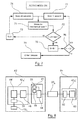
wing releasing device 42. When a fishing net (or any other foreign object) hits thelower wing 12c, drag applied to it increases and generates deflection of materials. The mechanical load sensor 49 (e.g. strain gage) is elongating accordingly and its resistance is evolving proportionally to the mechanical load. As shown inFigure 7 , an algorithm is implemented by the electronics 44 (i.e. the "releasing decision circuit"). Instep 71, theelectronics 44 receives from the mechanical load sensor 49 a measure of the mechanical load F. Intest step 72, theelectronics 44 compares this measure F with a threshold Fmax. In case of negative answer (i.e. if F<Fmax), the process goes to step 73, in which the counter N is set to 0, and then to step 74, which is a waiting step of 30 seconds, before returning tosetp 71. In case of affirmative answer, the process goes to step 75, in which the counter N is incremented by one, and then to teststep 76, in which theelectronics 44 compares N with a threshold (e.g. equal to 5). If N<5, then the process goes to step 77, which is a waiting step of 1 second, before returning tosetp 71. Otherwise, the process goes to step 78, in which the release request signal is generated (it is used to order theactuator 50 to release thelower wing 12c and associated shaft 5). - In the first embodiment described above, the electronics 44 ("releasing decision circuit") generates automatically a release request signal (used to activate an actuator 50), as a function of a load signal generated by a
load sensor 49. Alternative embodiments are possible since the electronics 44 ("releasing decision circuit") can generate the release request signal as a function of other types of measures, provided that these measures concern a parameter representative or related to a load applied on a wing. For example, it is possible any of the followings measures (this list is not exhaustive): - measures of a noise on data from one or several hydrophones (16) distributed along the
streamer 20a (these measures are visible directly from the seismic traces derived from the hydrophones ; a wing release decision can be made by analyzing these seismic traces, visually (by an operator who provides his decision via a man-machine interface) or even from a suitable algorithm (with template for example) in the case of an automatic solution); - measures of a noise on the
streamer 20a (these measures are obtained by load sensors placed along the cable, ideally in the vicinity of the birds, in order to measure an elongation or a shrinkage of the cable: e.g. elongation if a foreign object (e.g. a fishing net) does not tangle with the cable but is only pulled by the bird, and shrinkage (narrowing) if the fishing net wraps around the bird); - measures of a motor consumption of at least one
motorized wing 12a,12b; - ...
- Also, in alternative embodiments, when the releasing decision circuit is comprised in a management system on board a vessel (see
figure 8 described below), it can generate the release request signal either automatically or not. In the second case, an operator on board the vessel is provided with the measures (which are e.g. displayed on a screen), decides whether a foreign object is caught by the wing, and provides his decision (through a man-machine interface) to the releasing decision circuit which then generates the release request signal (if the operator has decided that a foreign object is caught). - We now describe the operation of the
inline module 41. The magnetic sensor 54 (e.g. magnetometer) measures the whole magnetic field created by the environment, including: Earth magnetic field, magnetic field generated by theelectronics 55, wires inside theinline module 41 and magnetic field generated by themagnet 52 situated inside thelower wing 12c. When thelower wing 12c is released (see above description of the operation of the wing releasing device 42), itsmagnet 52 moves far away from themagnetic sensor 54, the magnetic sudden change is detected as follows. - The
electronics 55 carries out several functions (each of these functions can be seen like a specific circuit of an operation managing system): - first function ("wing loss decision circuit"): it processes data coming from the
magnetic sensor 54 and detects the change related to the releasedwing 12c (i.e. a wireless magnetic feedback is used to give status of presence/absence of thelower wing 12c). When the change is detected, it generates a wing loss signal (also referred to as "absence signal"); - second function ("alarm circuit"): it raises and sends an alarm (absence signal) to a management system on-board the seismic vessel, so that the operator is informed that the
lower wing 12c has been released; - third function ("driving circuit"): when receiving the wing loss signal, it drives the bird according to a degraded operating mode, by adapting the behaviour of the two motorized
upper wings 12a and 12b. By adjusting the upper wings at the same angle of attack, twisting is reduced or removed. If twisting is removed, then all hydrodynamic forces are used to lift the streamer and so maintain a target vertical depth. In other words, when the lowernon-motorized wing 12c is released, the driving circuit acts on the two motorizedupper wings 12a, 12b to keep them symmetrical with respect to a longitudinal axis of thebody 11 and to control the depth of thestreamer 20a. - In an alternative embodiment (without wireless magnetic feedback) of the first function, the
electronics 55 receives (from theelectronics 44, via the radiocommunication means 48) a release information signal indicating the release of thelower wing 12c. - In an alternative embodiment, the degraded operating mode is defined as follows, when one of the two motorized
upper wings 12a, 12b is released: the driving circuit (electronics 55) acts on the other of the two motorized upper wings to control the depth of thestreamer 20a and to control an angle of attack at 0°, relative to a flow of water. - In a particular embodiment, electronics 44 (comprised in the wing releasing device 42) and electronics 55 (comprised in the inline module 41) each comprise a read-only memory (ROM) 440, 550, a random access memory (RAM) 441, 551 and a
processor only memory processor figure 7 for the function executed by theelectronics 44 comprised in the wing releasing device 42). Upon initialization, the aforementioned program code instructions are transferred from the read-only memory random access memory processor random access memory - All the steps of the methods executed by
electronics 55 andelectronics 44 can be implemented equally well: - by the execution of a set of program code instructions executed by a reprogrammable computing machine such as a PC type apparatus, a DSP (digital signal processor) or a microcontroller. This program code instructions can be stored in a non-transitory computer-readable carrier medium that is detachable (for example a floppy disk, a CD-ROM or a DVD-ROM) or non-detachable; or
- by a dedicated machine or component, such as an FPGA (Field Programmable Gate Array), an ASIC (Application-Specific Integrated Circuit) or any dedicated hardware component.
- Although the present disclosure has been described with reference to one or more examples, workers skilled in the art will recognize that changes may be made in form and detail without departing from the scope of the disclosure and/or the appended claims.
- The proposed solution is not limited to the release of the
lower wing 12c, and can be implemented with one or several wings (among the set of wings of the birds). - The proposed solution is not limited to the release of wing or wings of birds of the third type (e.g. Sercel's product called "Nautilus®"). Notably, it can also be implemented with birds of the first type ("Bird In Line"), i.e. when the body of the bird comprises a module placed in series along the streamer, and in that case the releasing decision circuit is comprised in the module or in one or several of the wings.
- We now present, in relation to
figure 8 , a bird 40', a wing releasing system 42a', 42b' and anoperation managing system 55 according to a second embodiment of the invention. - The bird 40' of the second embodiment differs from the
bird 40 of the first embodiment (seefigure 4 ) in that the electronics (referenced 44' infigure 8 ) still provides the release request signal to the actuator 50 (for releasing thelower wing 12c), but does not generate it. In other words, the electronics 44' does not perform the function of the releasing decision circuit. The releasingdecision circuit 83 is comprised in amanagement system 81, on board thevessel 21. - More precisley, the wing releasing system comprises:
- a first part 42b' (in the
management system 81 on board the vessel (21) comprising the releasingdecision circuit 83 and a transmitting circuit 82 (for transmitting the release request signal to the bird 40', via thestreamer 20a); and - a second part 42a' (in the bird 40') comprising the electronics 44', the
actuator 50, the wireless communication circuit 48 (for receiving the release request signal, via thestreamer 20a and a receivingcircuit 84 comprised in the inline module 41). - The releasing
decision circuit 83, comprised in the management system on board the vessel, can generate the release request signal either automatically (as theelectronics 44 in the embodiment offigure 4 ) or not. In the second case, an operator on board the vessel is provided with the measures (which are e.g. displayed on a screen), decides whether a foreign object is caught by the wing, and provides his decision (through a man-machine interface) to the releasingdecision circuit 83 which then generates the release request signal (if the operator has decided that a foreign object is caught).
Claims (12)
- Wing releasing system for releasing at least one wing (12a, 12b, 12c) of a set of wing or wings of a navigation control device (40, 40'), the navigation control device being adapted for controlling the depth and/or the lateral position of a towed acoustic linear antenna (20a) and comprising a body (11) to which is attached the set of wing or wings, the wing releasing system being characterized in that it comprises:- a releasing decision circuit (44, 83), for generating a release request signal when detecting that a foreign object is caught by at least one wing of the set of wing or wings; and- an actuator (50) comprised in the navigation control device, for releasing from the body said at least one wing of the set of wing or wings, when receiving said release request signal.
- Wing releasing system according to claim 1, characterized in that said releasing decision circuit (44, 83) comprises:- means for obtaining at least one measure of a parameter representative or related to a load applied on said at least one wing of the set of wing or wings;- means for deciding, automatically or through a man-machine interface, whether a foreign object is caught by said at least one wing of the set of wing or wings, based on said at least one measure; and- means for generating the release request signal if said means for deciding have decided that a foreign object is caught.
- Wing releasing system according to claim 2, characterized in that said means for deciding comprise signal processing means, with programmable settings.
- Wing releasing system according to claim 2 or 3, characterized in that said at least one measure belongs to the group comprising:- measures, from a load sensor (49) comprised in the navigation control device, of a load applied on said at least one wing of the set of wing or wings;- measures of a noise on data from one or several hydrophones (16) distributed along the towed acoustic linear antenna (20a);- measures of a noise on the towed acoustic linear antenna (20a); and- measures of a motor consumption of at least one motorized wing (12a,12b) of the set of wing or wings.
- Wing releasing system according to any one of the claims 1 to 4, characterized in that the releasing decision circuit (44) is comprised in the navigation control device (40).
- Wing releasing system according to claim 5, the navigation control device (40) comprising a module (41) placed in series along the towed acoustic linear antenna (20a), said body (11) freely rotating around said module, the wing releasing system being characterized in that said releasing decision circuit (44) is comprised in said body (11), in said module (41) or in said at least one wing of the set of wing or wings (12a, 12b, 12c).
- Wing releasing system according to claim 5, the body of the navigation control device comprising a module placed in series along the towed acoustic linear antenna, the wing releasing system being characterized in that said releasing decision circuit is comprised in said module or in said at least one wing of the set of wing or wings.
- Wing releasing system according to any one of the claims 1 to 4, characterized in that said releasing decision circuit (83) is comprised in a management system (81) on board a vessel (21), and in that the wing releasing system further comprises:- a transmitting circuit (82), comprised in the management system, for transmitting the release request signal to the actuator, and- a receiving circuit (48), comprised in the navigation control device, for receiving the release request signal.
- Wing releasing system according to any one of the claims 5 to 7, characterized in that it comprises a main battery (45), for powering the releasing decision circuit (44) and the actuator (50).
- Wing releasing system according to claim 9, characterized in that said releasing decision circuit (44), said actuator (50) and said main battery (45) are contained in a watertight housing (43a,43b) comprising a watertight connector (47), and in that said watertight connector is connected to said releasing decision circuit, said actuator and said main battery, and comprises means for cooperation with:- a shunting dongle (59), in order to desactivate the actuator and disconnect the main battery from the releasing decision circuit;- a passing dongle (60), in order to activate the actuator and connect the main battery to the releasing decision circuit;- a bench (61), in order to desactivate the actuator, charge the main battery and exchange data with the releasing decision circuit.
- Wing releasing system according to any one of the claims 1 to 10, characterized in that the releasing decision circuit (44) comprises an embedded memory to log events and record load cases.
- Method for releasing at least one wing (12a, 12b, 12c) of a set of wing or wings of a navigation control device (40, 40') adapted for controlling the depth and/or the lateral position of a towed acoustic linear antenna (20a) and comprising a body (11) to which is attached the set of wing or wings, the method being characterized in that it comprises the following steps:- generating a release request signal when detecting that a foreign object is caught by at least one wing of the set of wing or wings; and- releasing from the body said at least one wing of the set of wing or wings, using an actuator (50) comprised in the navigation control device, when said release request signal is generated.
Priority Applications (7)
| Application Number | Priority Date | Filing Date | Title |
|---|---|---|---|
| EP13306384.2A EP2857868B1 (en) | 2013-10-07 | 2013-10-07 | Wing releasing system for a navigation control device |
| CA2866013A CA2866013C (en) | 2013-10-07 | 2014-10-02 | Wing releasing system for a navigation control device |
| BR102014024957-5A BR102014024957B1 (en) | 2013-10-07 | 2014-10-06 | wing release system for a navigation control device |
| MX2014012075A MX352717B (en) | 2013-10-07 | 2014-10-06 | Wing releasing system for a navigation control device. |
| RU2014140321A RU2014140321A (en) | 2013-10-07 | 2014-10-06 | WING DISCONNECTION SYSTEM IN NAVIGATION CONTROL DEVICE |
| US14/508,559 US9475553B2 (en) | 2013-10-07 | 2014-10-07 | Wing releasing system for a navigation control device |
| CN201410525116.7A CN104516020B (en) | 2013-10-07 | 2014-10-08 | Wing for Navigation Control Unit discharges system |
Applications Claiming Priority (1)
| Application Number | Priority Date | Filing Date | Title |
|---|---|---|---|
| EP13306384.2A EP2857868B1 (en) | 2013-10-07 | 2013-10-07 | Wing releasing system for a navigation control device |
Publications (2)
| Publication Number | Publication Date |
|---|---|
| EP2857868A1 true EP2857868A1 (en) | 2015-04-08 |
| EP2857868B1 EP2857868B1 (en) | 2018-12-05 |
Family
ID=49484245
Family Applications (1)
| Application Number | Title | Priority Date | Filing Date |
|---|---|---|---|
| EP13306384.2A Active EP2857868B1 (en) | 2013-10-07 | 2013-10-07 | Wing releasing system for a navigation control device |
Country Status (7)
| Country | Link |
|---|---|
| US (1) | US9475553B2 (en) |
| EP (1) | EP2857868B1 (en) |
| CN (1) | CN104516020B (en) |
| BR (1) | BR102014024957B1 (en) |
| CA (1) | CA2866013C (en) |
| MX (1) | MX352717B (en) |
| RU (1) | RU2014140321A (en) |
Families Citing this family (6)
| Publication number | Priority date | Publication date | Assignee | Title |
|---|---|---|---|---|
| US10168441B1 (en) | 2017-06-19 | 2019-01-01 | Sercel | Seismic streamer connecting module and method |
| US10618606B2 (en) | 2017-10-25 | 2020-04-14 | Sercel | Streamer connecting module and method |
| RU181795U1 (en) * | 2018-03-02 | 2018-07-26 | федеральное государственное бюджетное образовательное учреждение высшего образования "Санкт-Петербургский государственный морской технический университет" (СПбГМТУ) | UNDERWATER WITH WING SYSTEM |
| US10562598B1 (en) | 2018-11-30 | 2020-02-18 | Sercel | Retriever system for a marine equipment and method |
| CN110576954B (en) * | 2019-08-29 | 2024-04-02 | 自然资源部第二海洋研究所 | Towed system for observing chemical parameters of water transverse and longitudinal sections |
| CN115583325B (en) * | 2022-10-26 | 2023-05-26 | 中国船舶科学研究中心 | Propeller discarding device special for manned submersible and operation method |
Citations (9)
| Publication number | Priority date | Publication date | Assignee | Title |
|---|---|---|---|---|
| EP0909701A2 (en) * | 1997-10-15 | 1999-04-21 | The Laitram Corporation | Underwater device with a sacrificial latch mechanism |
| US6525992B1 (en) | 1995-09-22 | 2003-02-25 | Input/Output, Inc. | Devices for controlling the position of an underwater cable |
| US7080607B2 (en) | 1998-10-01 | 2006-07-25 | Westerngeco, L.L.C. | Seismic data acquisiton equipment control system |
| US7206254B2 (en) | 1995-09-22 | 2007-04-17 | Input/Output, Inc. | Underwater cable arrangements and devices |
| US20080008033A1 (en) * | 2006-07-07 | 2008-01-10 | Kongsberg Seatex As | Method and system for controlling the position of marine seismic streamers |
| US20080192570A1 (en) * | 2007-02-14 | 2008-08-14 | Stig Rune Lennart Tenghamn | Lateral force and depth control device for marine seismic sensor array |
| WO2009088291A1 (en) * | 2008-01-09 | 2009-07-16 | Kongsberg Seatex As | Device for controlling the position of a instrument cable towed in water |
| US20090204274A1 (en) | 1996-12-20 | 2009-08-13 | Simon Hastings Bittleston | Control Devices for Controlling the Position of a Marine Seismic Streamer |
| US20100239367A1 (en) * | 2009-03-23 | 2010-09-23 | Ion Geophysical Corporation | Streamer connection system |
Family Cites Families (5)
| Publication number | Priority date | Publication date | Assignee | Title |
|---|---|---|---|---|
| US6011752A (en) * | 1998-08-03 | 2000-01-04 | Western Atlas International, Inc. | Seismic streamer position control module |
| GB9913864D0 (en) * | 1999-06-15 | 1999-08-11 | Shattock Bernard A | Hydrofoil apparatus |
| CN100353144C (en) * | 2005-01-31 | 2007-12-05 | 华南理工大学 | Controllable underwater towing body |
| FR2917063B1 (en) * | 2007-06-07 | 2009-12-04 | Cybernetix | DEVICE FOR CLOSING A FUSELAGE RELATING TO A SUBMARINE OBJECT TRAILER AND EQUIP EQUIPPED THEREWITH |
| NO332563B1 (en) * | 2009-07-07 | 2012-10-29 | Kongsberg Seatex As | System and method for positioning instrumented rope cable in water |
-
2013
- 2013-10-07 EP EP13306384.2A patent/EP2857868B1/en active Active
-
2014
- 2014-10-02 CA CA2866013A patent/CA2866013C/en active Active
- 2014-10-06 MX MX2014012075A patent/MX352717B/en active IP Right Grant
- 2014-10-06 BR BR102014024957-5A patent/BR102014024957B1/en active IP Right Grant
- 2014-10-06 RU RU2014140321A patent/RU2014140321A/en not_active Application Discontinuation
- 2014-10-07 US US14/508,559 patent/US9475553B2/en active Active
- 2014-10-08 CN CN201410525116.7A patent/CN104516020B/en active Active
Patent Citations (10)
| Publication number | Priority date | Publication date | Assignee | Title |
|---|---|---|---|---|
| US6525992B1 (en) | 1995-09-22 | 2003-02-25 | Input/Output, Inc. | Devices for controlling the position of an underwater cable |
| US7206254B2 (en) | 1995-09-22 | 2007-04-17 | Input/Output, Inc. | Underwater cable arrangements and devices |
| US20090204274A1 (en) | 1996-12-20 | 2009-08-13 | Simon Hastings Bittleston | Control Devices for Controlling the Position of a Marine Seismic Streamer |
| EP0909701A2 (en) * | 1997-10-15 | 1999-04-21 | The Laitram Corporation | Underwater device with a sacrificial latch mechanism |
| US7080607B2 (en) | 1998-10-01 | 2006-07-25 | Westerngeco, L.L.C. | Seismic data acquisiton equipment control system |
| US20080008033A1 (en) * | 2006-07-07 | 2008-01-10 | Kongsberg Seatex As | Method and system for controlling the position of marine seismic streamers |
| US7933163B2 (en) | 2006-07-07 | 2011-04-26 | Kongsberg Seatex As | Method and system for controlling the position of marine seismic streamers |
| US20080192570A1 (en) * | 2007-02-14 | 2008-08-14 | Stig Rune Lennart Tenghamn | Lateral force and depth control device for marine seismic sensor array |
| WO2009088291A1 (en) * | 2008-01-09 | 2009-07-16 | Kongsberg Seatex As | Device for controlling the position of a instrument cable towed in water |
| US20100239367A1 (en) * | 2009-03-23 | 2010-09-23 | Ion Geophysical Corporation | Streamer connection system |
Also Published As
| Publication number | Publication date |
|---|---|
| CN104516020A (en) | 2015-04-15 |
| US9475553B2 (en) | 2016-10-25 |
| MX352717B (en) | 2017-12-06 |
| RU2014140321A (en) | 2016-04-27 |
| CA2866013A1 (en) | 2015-04-07 |
| US20150096484A1 (en) | 2015-04-09 |
| BR102014024957B1 (en) | 2021-05-25 |
| EP2857868B1 (en) | 2018-12-05 |
| BR102014024957A2 (en) | 2015-10-06 |
| CA2866013C (en) | 2021-06-01 |
| MX2014012075A (en) | 2015-04-29 |
| CN104516020B (en) | 2018-12-04 |
Similar Documents
| Publication | Publication Date | Title |
|---|---|---|
| US9475553B2 (en) | Wing releasing system for a navigation control device | |
| US9599736B2 (en) | Operation managing system for driving a navigation control device according to a degraded operating mode | |
| US20160041283A1 (en) | Overboard system for deployment and retrieval of autonomous seismic nodes | |
| EP3064968A2 (en) | Drag body with inertial navigation system and method for determining position | |
| CN103852792A (en) | Head-float and method | |
| EP2372401A1 (en) | Method for towing marine sensor streamers | |
| DK201770945A1 (en) | Smart streamer recovery device | |
| AU2014201353B2 (en) | Streamers without tailbuoys | |
| US9488745B2 (en) | Method for estimating the water speed of an acoustic node | |
| EP2759851B1 (en) | System for real-time deflector monitoring and related methods | |
| EP2910978A1 (en) | Retriever system for a streamer | |
| WO2015177637A1 (en) | System and methods to manage a front-end of a seismic array | |
| KR20160093315A (en) | System for tow-fish type lose prevention and management method of the same | |
| RU157308U1 (en) | DEVICE FOR WORKING WITH BOTTOM GEOPHYSICAL STATIONS | |
| NO20150754A1 (en) | System for deploying an instrument at a seafloor | |
| NO335803B1 (en) | Method and optical device for providing information about the surroundings of an instrumented cable towed in the sea |
Legal Events
| Date | Code | Title | Description |
|---|---|---|---|
| PUAI | Public reference made under article 153(3) epc to a published international application that has entered the european phase |
Free format text: ORIGINAL CODE: 0009012 |
|
| 17P | Request for examination filed |
Effective date: 20131007 |
|
| AK | Designated contracting states |
Kind code of ref document: A1 Designated state(s): AL AT BE BG CH CY CZ DE DK EE ES FI FR GB GR HR HU IE IS IT LI LT LU LV MC MK MT NL NO PL PT RO RS SE SI SK SM TR |
|
| AX | Request for extension of the european patent |
Extension state: BA ME |
|
| R17P | Request for examination filed (corrected) |
Effective date: 20150522 |
|
| RBV | Designated contracting states (corrected) |
Designated state(s): AL AT BE BG CH CY CZ DE DK EE ES FI FR GB GR HR HU IE IS IT LI LT LU LV MC MK MT NL NO PL PT RO RS SE SI SK SM TR |
|
| GRAP | Despatch of communication of intention to grant a patent |
Free format text: ORIGINAL CODE: EPIDOSNIGR1 |
|
| STAA | Information on the status of an ep patent application or granted ep patent |
Free format text: STATUS: GRANT OF PATENT IS INTENDED |
|
| RIC1 | Information provided on ipc code assigned before grant |
Ipc: G01V 1/38 20060101AFI20180706BHEP |
|
| INTG | Intention to grant announced |
Effective date: 20180730 |
|
| GRAS | Grant fee paid |
Free format text: ORIGINAL CODE: EPIDOSNIGR3 |
|
| GRAA | (expected) grant |
Free format text: ORIGINAL CODE: 0009210 |
|
| STAA | Information on the status of an ep patent application or granted ep patent |
Free format text: STATUS: THE PATENT HAS BEEN GRANTED |
|
| AK | Designated contracting states |
Kind code of ref document: B1 Designated state(s): AL AT BE BG CH CY CZ DE DK EE ES FI FR GB GR HR HU IE IS IT LI LT LU LV MC MK MT NL NO PL PT RO RS SE SI SK SM TR |
|
| REG | Reference to a national code |
Ref country code: GB Ref legal event code: FG4D |
|
| REG | Reference to a national code |
Ref country code: CH Ref legal event code: EP |
|
| REG | Reference to a national code |
Ref country code: AT Ref legal event code: REF Ref document number: 1073766 Country of ref document: AT Kind code of ref document: T Effective date: 20181215 |
|
| REG | Reference to a national code |
Ref country code: IE Ref legal event code: FG4D |
|
| REG | Reference to a national code |
Ref country code: DE Ref legal event code: R096 Ref document number: 602013047727 Country of ref document: DE |
|
| REG | Reference to a national code |
Ref country code: NL Ref legal event code: MP Effective date: 20181205 |
|
| REG | Reference to a national code |
Ref country code: AT Ref legal event code: MK05 Ref document number: 1073766 Country of ref document: AT Kind code of ref document: T Effective date: 20181205 |
|
| REG | Reference to a national code |
Ref country code: LT Ref legal event code: MG4D |
|
| PG25 | Lapsed in a contracting state [announced via postgrant information from national office to epo] |
Ref country code: FI Free format text: LAPSE BECAUSE OF FAILURE TO SUBMIT A TRANSLATION OF THE DESCRIPTION OR TO PAY THE FEE WITHIN THE PRESCRIBED TIME-LIMIT Effective date: 20181205 Ref country code: BG Free format text: LAPSE BECAUSE OF FAILURE TO SUBMIT A TRANSLATION OF THE DESCRIPTION OR TO PAY THE FEE WITHIN THE PRESCRIBED TIME-LIMIT Effective date: 20190305 Ref country code: LT Free format text: LAPSE BECAUSE OF FAILURE TO SUBMIT A TRANSLATION OF THE DESCRIPTION OR TO PAY THE FEE WITHIN THE PRESCRIBED TIME-LIMIT Effective date: 20181205 Ref country code: LV Free format text: LAPSE BECAUSE OF FAILURE TO SUBMIT A TRANSLATION OF THE DESCRIPTION OR TO PAY THE FEE WITHIN THE PRESCRIBED TIME-LIMIT Effective date: 20181205 Ref country code: HR Free format text: LAPSE BECAUSE OF FAILURE TO SUBMIT A TRANSLATION OF THE DESCRIPTION OR TO PAY THE FEE WITHIN THE PRESCRIBED TIME-LIMIT Effective date: 20181205 Ref country code: ES Free format text: LAPSE BECAUSE OF FAILURE TO SUBMIT A TRANSLATION OF THE DESCRIPTION OR TO PAY THE FEE WITHIN THE PRESCRIBED TIME-LIMIT Effective date: 20181205 Ref country code: AT Free format text: LAPSE BECAUSE OF FAILURE TO SUBMIT A TRANSLATION OF THE DESCRIPTION OR TO PAY THE FEE WITHIN THE PRESCRIBED TIME-LIMIT Effective date: 20181205 |
|
| REG | Reference to a national code |
Ref country code: NO Ref legal event code: T2 Effective date: 20181205 |
|
| PG25 | Lapsed in a contracting state [announced via postgrant information from national office to epo] |
Ref country code: GR Free format text: LAPSE BECAUSE OF FAILURE TO SUBMIT A TRANSLATION OF THE DESCRIPTION OR TO PAY THE FEE WITHIN THE PRESCRIBED TIME-LIMIT Effective date: 20190306 Ref country code: RS Free format text: LAPSE BECAUSE OF FAILURE TO SUBMIT A TRANSLATION OF THE DESCRIPTION OR TO PAY THE FEE WITHIN THE PRESCRIBED TIME-LIMIT Effective date: 20181205 Ref country code: SE Free format text: LAPSE BECAUSE OF FAILURE TO SUBMIT A TRANSLATION OF THE DESCRIPTION OR TO PAY THE FEE WITHIN THE PRESCRIBED TIME-LIMIT Effective date: 20181205 Ref country code: AL Free format text: LAPSE BECAUSE OF FAILURE TO SUBMIT A TRANSLATION OF THE DESCRIPTION OR TO PAY THE FEE WITHIN THE PRESCRIBED TIME-LIMIT Effective date: 20181205 |
|
| PG25 | Lapsed in a contracting state [announced via postgrant information from national office to epo] |
Ref country code: NL Free format text: LAPSE BECAUSE OF FAILURE TO SUBMIT A TRANSLATION OF THE DESCRIPTION OR TO PAY THE FEE WITHIN THE PRESCRIBED TIME-LIMIT Effective date: 20181205 |
|
| PG25 | Lapsed in a contracting state [announced via postgrant information from national office to epo] |
Ref country code: CZ Free format text: LAPSE BECAUSE OF FAILURE TO SUBMIT A TRANSLATION OF THE DESCRIPTION OR TO PAY THE FEE WITHIN THE PRESCRIBED TIME-LIMIT Effective date: 20181205 Ref country code: PT Free format text: LAPSE BECAUSE OF FAILURE TO SUBMIT A TRANSLATION OF THE DESCRIPTION OR TO PAY THE FEE WITHIN THE PRESCRIBED TIME-LIMIT Effective date: 20190405 Ref country code: IT Free format text: LAPSE BECAUSE OF FAILURE TO SUBMIT A TRANSLATION OF THE DESCRIPTION OR TO PAY THE FEE WITHIN THE PRESCRIBED TIME-LIMIT Effective date: 20181205 Ref country code: PL Free format text: LAPSE BECAUSE OF FAILURE TO SUBMIT A TRANSLATION OF THE DESCRIPTION OR TO PAY THE FEE WITHIN THE PRESCRIBED TIME-LIMIT Effective date: 20181205 |
|
| PG25 | Lapsed in a contracting state [announced via postgrant information from national office to epo] |
Ref country code: SK Free format text: LAPSE BECAUSE OF FAILURE TO SUBMIT A TRANSLATION OF THE DESCRIPTION OR TO PAY THE FEE WITHIN THE PRESCRIBED TIME-LIMIT Effective date: 20181205 Ref country code: RO Free format text: LAPSE BECAUSE OF FAILURE TO SUBMIT A TRANSLATION OF THE DESCRIPTION OR TO PAY THE FEE WITHIN THE PRESCRIBED TIME-LIMIT Effective date: 20181205 Ref country code: IS Free format text: LAPSE BECAUSE OF FAILURE TO SUBMIT A TRANSLATION OF THE DESCRIPTION OR TO PAY THE FEE WITHIN THE PRESCRIBED TIME-LIMIT Effective date: 20190405 Ref country code: EE Free format text: LAPSE BECAUSE OF FAILURE TO SUBMIT A TRANSLATION OF THE DESCRIPTION OR TO PAY THE FEE WITHIN THE PRESCRIBED TIME-LIMIT Effective date: 20181205 Ref country code: SM Free format text: LAPSE BECAUSE OF FAILURE TO SUBMIT A TRANSLATION OF THE DESCRIPTION OR TO PAY THE FEE WITHIN THE PRESCRIBED TIME-LIMIT Effective date: 20181205 |
|
| REG | Reference to a national code |
Ref country code: DE Ref legal event code: R097 Ref document number: 602013047727 Country of ref document: DE |
|
| PLBE | No opposition filed within time limit |
Free format text: ORIGINAL CODE: 0009261 |
|
| STAA | Information on the status of an ep patent application or granted ep patent |
Free format text: STATUS: NO OPPOSITION FILED WITHIN TIME LIMIT |
|
| PG25 | Lapsed in a contracting state [announced via postgrant information from national office to epo] |
Ref country code: DK Free format text: LAPSE BECAUSE OF FAILURE TO SUBMIT A TRANSLATION OF THE DESCRIPTION OR TO PAY THE FEE WITHIN THE PRESCRIBED TIME-LIMIT Effective date: 20181205 Ref country code: SI Free format text: LAPSE BECAUSE OF FAILURE TO SUBMIT A TRANSLATION OF THE DESCRIPTION OR TO PAY THE FEE WITHIN THE PRESCRIBED TIME-LIMIT Effective date: 20181205 |
|
| 26N | No opposition filed |
Effective date: 20190906 |
|
| PG25 | Lapsed in a contracting state [announced via postgrant information from national office to epo] |
Ref country code: TR Free format text: LAPSE BECAUSE OF FAILURE TO SUBMIT A TRANSLATION OF THE DESCRIPTION OR TO PAY THE FEE WITHIN THE PRESCRIBED TIME-LIMIT Effective date: 20181205 |
|
| REG | Reference to a national code |
Ref country code: DE Ref legal event code: R119 Ref document number: 602013047727 Country of ref document: DE |
|
| PG25 | Lapsed in a contracting state [announced via postgrant information from national office to epo] |
Ref country code: MC Free format text: LAPSE BECAUSE OF FAILURE TO SUBMIT A TRANSLATION OF THE DESCRIPTION OR TO PAY THE FEE WITHIN THE PRESCRIBED TIME-LIMIT Effective date: 20181205 |
|
| REG | Reference to a national code |
Ref country code: CH Ref legal event code: PL |
|
| PG25 | Lapsed in a contracting state [announced via postgrant information from national office to epo] |
Ref country code: DE Free format text: LAPSE BECAUSE OF NON-PAYMENT OF DUE FEES Effective date: 20200501 Ref country code: CH Free format text: LAPSE BECAUSE OF NON-PAYMENT OF DUE FEES Effective date: 20191031 Ref country code: LI Free format text: LAPSE BECAUSE OF NON-PAYMENT OF DUE FEES Effective date: 20191031 Ref country code: LU Free format text: LAPSE BECAUSE OF NON-PAYMENT OF DUE FEES Effective date: 20191007 |
|
| REG | Reference to a national code |
Ref country code: BE Ref legal event code: MM Effective date: 20191031 |
|
| PG25 | Lapsed in a contracting state [announced via postgrant information from national office to epo] |
Ref country code: BE Free format text: LAPSE BECAUSE OF NON-PAYMENT OF DUE FEES Effective date: 20191031 |
|
| PG25 | Lapsed in a contracting state [announced via postgrant information from national office to epo] |
Ref country code: IE Free format text: LAPSE BECAUSE OF NON-PAYMENT OF DUE FEES Effective date: 20191007 |
|
| PG25 | Lapsed in a contracting state [announced via postgrant information from national office to epo] |
Ref country code: CY Free format text: LAPSE BECAUSE OF FAILURE TO SUBMIT A TRANSLATION OF THE DESCRIPTION OR TO PAY THE FEE WITHIN THE PRESCRIBED TIME-LIMIT Effective date: 20181205 |
|
| PG25 | Lapsed in a contracting state [announced via postgrant information from national office to epo] |
Ref country code: HU Free format text: LAPSE BECAUSE OF FAILURE TO SUBMIT A TRANSLATION OF THE DESCRIPTION OR TO PAY THE FEE WITHIN THE PRESCRIBED TIME-LIMIT; INVALID AB INITIO Effective date: 20131007 Ref country code: MT Free format text: LAPSE BECAUSE OF FAILURE TO SUBMIT A TRANSLATION OF THE DESCRIPTION OR TO PAY THE FEE WITHIN THE PRESCRIBED TIME-LIMIT Effective date: 20181205 |
|
| PG25 | Lapsed in a contracting state [announced via postgrant information from national office to epo] |
Ref country code: MK Free format text: LAPSE BECAUSE OF FAILURE TO SUBMIT A TRANSLATION OF THE DESCRIPTION OR TO PAY THE FEE WITHIN THE PRESCRIBED TIME-LIMIT Effective date: 20181205 |
|
| PGFP | Annual fee paid to national office [announced via postgrant information from national office to epo] |
Ref country code: GB Payment date: 20231020 Year of fee payment: 11 |
|
| PGFP | Annual fee paid to national office [announced via postgrant information from national office to epo] |
Ref country code: NO Payment date: 20231025 Year of fee payment: 11 Ref country code: FR Payment date: 20231025 Year of fee payment: 11 |