EP2857823A1 - Exhaust gas dilution device - Google Patents
Exhaust gas dilution device Download PDFInfo
- Publication number
- EP2857823A1 EP2857823A1 EP13797667.6A EP13797667A EP2857823A1 EP 2857823 A1 EP2857823 A1 EP 2857823A1 EP 13797667 A EP13797667 A EP 13797667A EP 2857823 A1 EP2857823 A1 EP 2857823A1
- Authority
- EP
- European Patent Office
- Prior art keywords
- exhaust gas
- flow rate
- flowing
- dilution
- measurement instrument
- Prior art date
- Legal status (The legal status is an assumption and is not a legal conclusion. Google has not performed a legal analysis and makes no representation as to the accuracy of the status listed.)
- Withdrawn
Links
Images

Classifications
-
- G—PHYSICS
- G01—MEASURING; TESTING
- G01N—INVESTIGATING OR ANALYSING MATERIALS BY DETERMINING THEIR CHEMICAL OR PHYSICAL PROPERTIES
- G01N1/00—Sampling; Preparing specimens for investigation
- G01N1/02—Devices for withdrawing samples
- G01N1/22—Devices for withdrawing samples in the gaseous state
- G01N1/2247—Sampling from a flowing stream of gas
- G01N1/2252—Sampling from a flowing stream of gas in a vehicle exhaust
-
- G—PHYSICS
- G01—MEASURING; TESTING
- G01M—TESTING STATIC OR DYNAMIC BALANCE OF MACHINES OR STRUCTURES; TESTING OF STRUCTURES OR APPARATUS, NOT OTHERWISE PROVIDED FOR
- G01M15/00—Testing of engines
- G01M15/04—Testing internal-combustion engines
- G01M15/10—Testing internal-combustion engines by monitoring exhaust gases or combustion flame
- G01M15/102—Testing internal-combustion engines by monitoring exhaust gases or combustion flame by monitoring exhaust gases
-
- G—PHYSICS
- G01—MEASURING; TESTING
- G01N—INVESTIGATING OR ANALYSING MATERIALS BY DETERMINING THEIR CHEMICAL OR PHYSICAL PROPERTIES
- G01N33/00—Investigating or analysing materials by specific methods not covered by groups G01N1/00 - G01N31/00
- G01N33/0004—Gaseous mixtures, e.g. polluted air
- G01N33/0009—General constructional details of gas analysers, e.g. portable test equipment
- G01N33/0011—Sample conditioning
- G01N33/0018—Sample conditioning by diluting a gas
-
- G—PHYSICS
- G01—MEASURING; TESTING
- G01N—INVESTIGATING OR ANALYSING MATERIALS BY DETERMINING THEIR CHEMICAL OR PHYSICAL PROPERTIES
- G01N33/00—Investigating or analysing materials by specific methods not covered by groups G01N1/00 - G01N31/00
- G01N33/0004—Gaseous mixtures, e.g. polluted air
- G01N33/0009—General constructional details of gas analysers, e.g. portable test equipment
- G01N33/0022—General constructional details of gas analysers, e.g. portable test equipment using a number of analysing channels
-
- G—PHYSICS
- G01—MEASURING; TESTING
- G01N—INVESTIGATING OR ANALYSING MATERIALS BY DETERMINING THEIR CHEMICAL OR PHYSICAL PROPERTIES
- G01N1/00—Sampling; Preparing specimens for investigation
- G01N1/02—Devices for withdrawing samples
- G01N1/22—Devices for withdrawing samples in the gaseous state
- G01N1/2247—Sampling from a flowing stream of gas
- G01N1/2252—Sampling from a flowing stream of gas in a vehicle exhaust
- G01N2001/2255—Sampling from a flowing stream of gas in a vehicle exhaust with dilution of the sample
Definitions
- the present invention relates to an exhaust gas dilution device to be used in an exhaust gas measurement system for measuring components of exhaust gas discharged from an internal combustion engine such as an engine.
- a system for measuring particulate matters (PM) contained in engine exhaust gas is configured so as to dilute sampled engine exhaust gas with dilution air and lead the diluted exhaust gas to a PM collecting filter to thereby collect PM.
- a ratio (Q2/Q1) between an engine exhaust gas flow rate Q1 flowing through an exhaust pipe and a sampled engine exhaust gas flow rate Q2 is made constant.
- a mass of the PM collected by this filter is obtained by weighing by a precision balance.
- a constant capacity dilution sampling device (CVS) is configured so that a whole quantity of engine exhaust gas is diluted with dilution air and controlled so as to make a total flow rate obtained by summing up them constant all the time and a part of the diluted engine exhaust gas is sampled in a bag at a constant flow rate.
- a ratio (Q 4 / Q 3 ) between a total flow rate Q 3 controlled by the CVS and a diluted exhaust gas Q 4 sampled to the bag is made constant.
- the diluted engine exhaust gas in the bag is analyzed by a gas analyzer.
- a bag mini-diluter (BMD) is configured so as to sample a part of engine exhaust gas to be diluted with dilution air so as to be a constant dilution ratio so that a part of the diluted engine exhaust gas is sampled to the bag at a flow rate proportional to the flow rate of the engine exhaust gas.
- a ratio (Q 5 / Q 1 ) between an engine exhaust gas flow rate Q 1 flowing through an exhaust pipe and a diluted exhaust gas flow rate Q 5 sampled to the bag is made constant.
- the diluted engine exhaust gas in the bag is analyzed by a gas analyzer.
- the present invention has been made in order to collectively solve the above problems, and an essential expected object thereof is intended that diluted exhaust gas is supplied to a plurality of measurement instruments including a PM measurement instrument and an exhaust gas measurement instrument by a single exhaust gas dilution device to thereby reduce in size an exhaust gas measurement system incorporated with the exhaust gas dilution device and to measure the exhaust gas diluted with the same exhaust gas under the same dilution condition in the plurality of measurement instruments including the PM measurement instruments and the exhaust gas measurement instruments.
- an exhaust gas dilution device includes:
- the diluted exhaust gas can be supplied to the plurality of measurement instruments including the PM measurement instrument and the exhaust gas measurement instrument by a single exhaust gas dilution device.
- the branching flow rate adjustment mechanism by the control device using the exhaust gas flow rate, as a parameter, indicated by the exhaust gas flow rate related signal flowing through the exhaust pipe, a dilution ratio or a diversion ratio of the diluted exhaust gas flowing through each of the measurement instruments can be made a desirable value.
- the exhaust gas measurement system incorporated with the exhaust gas dilution device of the present invention can be reduced in size, and since it is not necessary to prepare a dilution sampling device every measurement instrument, a cost can be also reduced. Further, since the exhaust gas diluted by a single exhaust gas dilution device can be supplied to the plurality of measurement instruments including the PM measurement instrument and the exhaust gas measurement instrument, the exhaust gas diluted with the same exhaust gas under the same dilution condition can be measured, and in the case where measurement results of the plurality of measurement instruments are compared, the reliability of the comparison results thereof can be improved.
- the diluted exhaust gas to be supplied to the plurality of measurement instruments including the PM measurement instrument and the exhaust gas measurement instrument is produced by a single exhaust gas dilution device, there is also an effect that it is easy to incorporate an application such as switching a sampling ON/OFF in synchronization with stopping and starting of an engine and switching a sampling ON/OFF by confirming a concentration of a prescribed component of the exhaust gas. Further, it is sufficient only to confirm an operation of a single exhaust gas dilution device, and therefore a maintenance work can be also facilitated.
- the exhaust gas dilution device since the exhaust gas dilution device includes the branching flow rate adjustment mechanism, the configuration of the measurement instrument lines connected to the exhaust gas dilution device can be simplified.
- an exhaust gas dilution device includes:
- the diluted exhaust gas can be supplied to the plurality of measurement instruments including the PM measurement instrument and the exhaust gas measurement instrument by a single exhaust gas dilution device.
- the branching flow rate adjustment mechanism by the control device using the exhaust gas flow rate, as a parameter, indicated by the exhaust gas flow rate related signal flowing through the exhaust pipe, a dilution ratio or a diversion ratio of the diluted exhaust gas flowing through each of the measurement instruments can be made a desirable value.
- the exhaust gas measurement system incorporated with the exhaust gas dilution device of the present invention can be reduced in size, and since it is not necessary to prepare a dilution sampling device every measurement instrument, a cost can be also reduced. Further, since the exhaust gas diluted by a single exhaust gas dilution device can be supplied to the plurality of measurement instruments including the PM measurement instrument and the exhaust gas measurement instrument, the exhaust gas diluted with the same exhaust gas under the same dilution condition can be measured, and in the case where measurement results of the plurality of measurement instruments including the PM measurement instrument and the exhaust gas measurement instrument are compared, the reliability of the comparison results thereof can be improved.
- the diluted exhaust gas to be supplied to the plurality of measurement instruments including the PM measurement instrument and the exhaust gas measurement instrument is produced by a single exhaust gas dilution device, there is also an effect that it is easy to incorporate an application such as switching a sampling ON/OFF in synchronization with stopping and starting of an engine or switching a sampling ON/OFF by confirming a concentration of a prescribed component of the exhaust gas. Further, it is sufficient only to confirm an operation of a single exhaust gas dilution device, and therefore a maintenance work can be also facilitated.
- the measurement instrument lines including the measurement instruments and the branching flow rate adjustment mechanisms are configured so as to be connected to the exhaust gas dilution device, it is not necessary to provide a branching flow rate adjustment mechanism in the exhaust gas dilution device, and therefore the exhaust gas dilution device can be reduced in size.
- a main flow rate adjustment mechanism provided in the main flow path to adjust the flow rate of the diluted exhaust gas flowing through the main flow path and that the flow rate adjustment mechanism control part controls the main flow rate adjustment mechanism or the plurality of branching flow rate adjustment mechanism using, as the parameter, the exhaust gas flow rate indicated by the exhaust gas flow rate related signal acquired by the exhaust gas flow rate acquisition part to thereby adjust the diluted exhaust gas flow rate flowing through the plurality of measurement instrument lines.
- the flow rate adjustment mechanism control part controls the main flow rate adjustment mechanism to thereby make a ratio constant between the exhaust gas flow rate flowing through the exhaust pipe and the sampling flow rate flowing through the sampling line.
- the flow rate adjustment mechanism control part controls the main flow rate adjustment mechanism to thereby make a ratio constant between the exhaust gas flow rate flowing through the exhaust pipe and the sampling flow rate flowing through the sampling line and controls the plurality of branching flow rate adjustment mechanisms to thereby make a ratio constant between the exhaust gas flow rate flowing through the exhaust pipe and the diluted exhaust gas flow rate flowing through each of the measurement instrument lines.
- a dilution ratio, a retention time and a temperature range inside the diluter are defined by a recent year exhaust gas testing restriction, since the same sampling conditions can be made irrespective of an engine size in the present method, a setting can be made in conformity with the exhaust gas testing restriction irrespective of the engine size.
- the flow rate adjustment mechanism control part controls the plurality of branching flow rate control mechanisms to thereby make a ratio constant between any two of the diluted exhaust gas flow rates flowing through the respective measurement instrument lines.
- the exhaust gas measurement system incorporated with the exhaust gas dilution device can be reduced in size, and the exhaust gas diluted with the same exhaust gas under the same dilution condition can be measured in a plurality of measurement instruments.
- the exhaust gas dilution device 100 is, for example, a portable one that samples a part of engine exhaust gas (simply referred to as "exhaust gas” hereinafter) flowing through an exhaust pipe EH connected to an engine E to be diluted and supplied to a plurality of measurement instruments.
- exhaust gas a part of engine exhaust gas
- this device includes: a sampling port 2 that is connected with a sampling line L1 which samples a part of exhaust gas flowing through an exhaust pipe EH as sampling gas; a dilution air supply port (dilution gas supply port) 3 that is connected with a dilution air supply line (dilution gas supply line) L2 which supplies dilution air as dilution gas for diluting the sampled exhaust gas; a single diluter 4 that communicates with the sampling port 2 and the dilution air supply port 3 to thereby dilute the sample gas with the dilution air; a main flow path 5 which is connected to the diluter 4 and through which the diluted exhaust gas diluted by the diluter 4 flows; a main flow rate adjustment mechanism 6 that is provided on the main flow path 5 to adjust a flow rate of the diluted exhaust gas flowing through the main flow path 5; a plurality of measurement instrument ports 7a to 7c that are provided in a plurality of branching flow paths
- a dilution air flow rate adjustment mechanism 11 for adjusting a dilution air flow rate flowing through the dilution air supply line L2 to be supplied to the diluter 4.
- This dilution air flow rate adjustment mechanism 11 is configured of a massflow controller and controlled by the control device 8 to be described later.
- the diluter 4 is a dilution tunnel having an upstream side connected with a first flow path 21 which has the sampling port 2 at one end and having the upstream side connected with a second flow path 31 which has the dilution air supply port 3 at one end.
- the main flow path 5 is connected to a downstream side of the dilution tunnel 4.
- the main flow rate adjustment mechanism 6 provided on the downstream side of the main flow path 5 is configured of a main flowmeter 61 for measuring a diluted exhaust gas flow rate flowing through the main flow path 5 and a revolution number controllable pump 62 provided on the downstream side of the main flowmeter 61.
- the revolution number of this pump 62 is controlled by the control device 8 to be described later.
- this main flow rate adjustment mechanism 6 is connected with a flow rate compensation line 63 for supplying to the main flow path 5 and compensating the flow rates flowing to the second measurement instrument (exhaust gas sampling bag 9b) and the third measurement instrument (exhaust gas analyzer 9c) to be described later.
- This flow rate compensation line 63 is connected to the upstream side of the main flowmeter 61 and is provided with a flowmeter 631 for measuring a flow rate of compensation air flowing through the flow rate compensation line 63.
- the plurality of measurement instrument ports 7a to 7c include: a first measurement instrument port 7a connected with the first measurement instrument line L3a provided with a PM collecting filter 9a which is a PM measurement instrument for collecting particulate matters (PM) contained in the diluted exhaust gas; a second measurement instrument port 7b connected with the second measurement instrument line L3b provided with an exhaust gas sampling bag 9b which is an exhaust gas measurement instrument for sampling the diluted exhaust gas; and a third measurement instrument port 7c connected with the third measurement instrument line L3c provided with an exhaust gas analyzer 9c for continuously measuring various components contained in the diluted exhaust gas.
- a first measurement instrument port 7a connected with the first measurement instrument line L3a provided with a PM collecting filter 9a which is a PM measurement instrument for collecting particulate matters (PM) contained in the diluted exhaust gas
- a second measurement instrument port 7b connected with the second measurement instrument line L3b provided with an exhaust gas sampling bag 9b which is an exhaust gas measurement instrument for sampling the diluted exhaust gas
- a third measurement instrument port 7c connected
- the first measurement instrument line L3a is provided with the first branching flow rate adjustment mechanism 10a on the downstream side of the PM collecting filter 9a.
- the first branching flow rate adjustment mechanism 10a of the present embodiment is configured of a first flowmeter 10a1 for measuring a flow rate of the diluted exhaust gas flowing through the first measurement instrument line L3a and a revolution number controllable first pump 10a2 provided on the downstream side of the first flowmeter 10a1.
- the revolution number of this first pump 10a2 is controlled by the control device 8 to be described later.
- the flow rate of the diluted exhaust gas flowing through the first measurement instrument line L3a is adjusted.
- a lower end portion of this first measurement instrument line L3a is connected to the main flow path 5.
- connection port 12 for connecting the downstream side of the first measurement instrument line L3a to the main flow path 5.
- a connection internal flow path 121 having this connection port 12 at one end is confluent with the main flow path 5 on the upstream side of the main flowmeter 61 of the main flow rate adjustment mechanism 6.
- the second measurement instrument line L3b is provided with the branching flow rate adjustment mechanism 10b such as a massflow controller for adjusting a flow rate of the diluted exhaust gas flowing through the second measurement instrument line L3b, on the upstream side of the exhaust gas sampling bag 9b.
- This branching flow rate adjustment mechanism 10b is controlled by the control device 8 to be described later.
- the control device 8 controls the control device 8 to be described later.
- the third measurement instrument line L3c is provided with the third flowmeter 10c1 for measuring the flow rate of the diluted exhaust gas flowing through the third measurement instrument line L3c, on the upstream side of the exhaust gas analyzer 9c. And by controlling a pump (not shown) provided inside the exhaust gas analyzer 9c by the control device 8 to be described later, the flow rate of the diluted exhaust gas flowing through the third measurement instrument line L3c is adjusted. That is, the branching flow rate adjustment mechanism 10c is configured of the third flowmeter 10c1 and the pump of the exhaust gas analyzer 9c.
- the control device 8 controls the main flow rate adjustment mechanism 6, the branching flow rate adjustment mechanisms 10a to 10c and a dilution air flow rate adjustment mechanism 11 based on the flow rate of the exhaust gas flowing through the exhaust pipe EH so as to be a proportional sampling by a predetermined dilution ratio and a diversion ratio.
- this control device 8 is a general-purpose and dedicated computer provided with a CPU, a memory, an I/O interface, an AD converter and the like, and by rendering the CPU, peripherals and the like to be in cooperation in accordance with a predetermined program stored in a predetermined area of the memory, there exhibits functions as an exhaust gas flow rate acquisition part 81, a flow rate adjustment mechanism control part 82 and the like, as shown in Fig. 2 .
- the exhaust gas flow rate acquisition part 81 acquires an exhaust gas flow rate related signal which is a measurement signal directly indicating an exhaust gas flow rate from an exhaust gas flowmeter 13 which is provided on the exhaust pipe EH to measure an exhaust gas flow rate Q A flowing through the exhaust pipe EH. Then, the exhaust gas flow rate acquisition part 81 outputs the exhaust gas flow rate related signal acquired from the exhaust gas flowmeter 13 to the flow rate adjustment mechanism control part 82.
- the exhaust gas flowmeter 13 a thermal type flowmeter, a pitot-tube type flowmeter, a differential pressure type flowmeter, an ultrasonic type flow meter and the like are available.
- the exhaust gas flow rate acquisition part 81 may also acquire an exhaust gas flow rate related signal indirectly indicating an exhaust gas flow rate Q A flowing through the exhaust pipe EH.
- an exhaust gas flow rate related signal indirectly indicating the exhaust gas flow rate Q A there may be considered such as an air-fuel ratio (A/F) of an engine.
- the flow rate adjustment mechanism control part 82 acquires the exhaust gas flow rate related signal to calculate the exhaust gas flow rate Q A indicated by the exhaust gas flow rate related signal and controls the main flow rate adjustment mechanism 6 and the branching flow rate adjustment mechanisms 10a to 10c using the exhaust gas flow rate Q A as follows. Note that, in the present embodiment, by controlling the dilution air flow rate adjustment mechanism 11 by the control device 8, a dilution air flow rate Q C is adjusted so as to make the dilution ratio in the diluter 4 constant.
- the flow rate adjustment mechanism control part 82 controls the main flow rate adjustment mechanism 6 based on the exhaust gas flow rate Q A and makes a ratio (Q B / Q A ) constant between the exhaust gas flow rate Q A flowing through the exhaust pipe EH and the sampling flow rate Q B flowing through the sampling line L1. Further, the flow rate adjustment mechanism control part 82 controls the first and second branching flow rate adjustment mechanisms 10a and 10b and makes ratios (Q D / Q A , Q E / Q A ) constant between the exhaust gas flow rate Q A flowing through the exhaust pipe EH and diluted exhaust gas flow rates Q D and Q E flowing through the first and second measurement instrument lines L3a and L3b. Note that the third branching flow rate adjustment mechanism 10c is controlled so that a diluted gas flow rate Q F flowing through the third measurement instrument line L3c becomes a sample gas flow rate measurable with a predetermined precision in the exhaust gas analyzer 9c.
- the dilution ratio of the diluted exhaust gas flowing through the first to third measurement instrument lines L3a to L3c becomes (Q B / (Q B + Q C )).
- the diversion ratio of the diluted exhaust gas flowing through the first measurement instrument line L3a becomes (Q B / Q A ⁇ Q D / (Q B + Q C ))
- the diversion ratio of the diluted exhaust gas flowing through the second measurement instrument line L3b becomes (Q B / Q A ⁇ Q E / (Q B + Q C ))
- the diversion ratio of the diluted exhaust gas flowing through the third measurement instrument line L3c becomes (Q B / Q A ⁇ Q F / (Q B + Q C )).
- the exhaust gas dilution device 100 by supplying the diluted exhaust gas to the plurality of measurement instruments 9a to 9c including the PM measurement instrument and the exhaust gas measurement instrument from the main flow path 5 through which the diluted exhaust gas diluted by the diluter 4 flows, via the branching flow paths 71a to 71c, the diluted exhaust gas can be supplied to the plurality of measurement instruments 9a to 9c including the PM measurement instrument and the exhaust gas measurement instrument by a single exhaust gas dilution device 100.
- the dilution ratio and the diversion ratio of the diluted exhaust gas flowing through the respective measurement instruments 9a and 9b can be made desirable values. Therefore, the exhaust gas measurement system incorporated with the exhaust gas dilution device 100 can be reduced in size, and since it is not necessary to prepare a dilution sampling device for each of the measurement instruments 9a to 9c, the cost can be also reduced.
- the exhaust gas diluted by a single exhaust gas dilution device 100 can be supplied to the plurality of measurement instruments 9a to 9c including the PM measurement instrument and the exhaust gas measurement instrument, the exhaust gas diluted with the same exhaust gas under the same dilution condition can be measured, and in the case where measurement results of the plurality of measurement instruments 9a to 9c including the PM measurement instrument and the exhaust gas measurement instrument are compared, the reliability of the comparison results thereof can be improved.
- the diluted exhaust gas to be supplied to the plurality of measurement instruments 9a to 9c including the PM measurement instrument and the exhaust gas measurement instrument is produced by a single exhaust gas dilution device 100, there is also an effect that it is easy to incorporate an application such as switching a sampling ON/OFF in synchronization with stopping and starting of an engine and switching a sampling ON/OFF by confirming a concentration of a prescribed component of the exhaust gas. Further, it is sufficient only to confirm an operation of a single exhaust gas dilution device 100, and therefore a maintenance work can be also facilitated.
- the measurement instrument lines L3a to L3c including the measurement instruments 9a to 9c and the branching flow rate adjustment mechanisms 10a to 10c are configured so as to be connected to the exhaust gas dilution device 100, it is not necessary to provide a branching flow rate adjustment mechanism in the exhaust gas dilution device 100, and therefore the exhaust gas dilution device 100 can be reduced in size.
- the exhaust gas dilution device 100 includes the sample gas port 2, the dilution air supply port 3, the plurality of measurement instrument ports 7a to 7c and the like, each line may be only connected after setting in a predetermined place, it can be appropriately used as a portable one.
- a dilution ratio, a retention time and a temperature range inside the diluter 4 are defined by a recent exhaust gas testing restriction, since the same sampling conditions can be made irrespective of an engine size in the present method, a setting can be made in conformity with the exhaust gas testing restriction irrespective of the engine size.
- the flow rate adjustment mechanism control part 82 of the embodiment may be configured so as to control the main flow rate adjustment mechanism 6 and the branching flow rate adjustment mechanisms 10a and 10b as follows. That is, the flow rate adjustment mechanism control part 82 controls the main flow rate adjustment mechanism 6 and makes a ratio (Q B / Q A ) constant between the exhaust gas flow rate Q A flowing through the exhaust pipe EH and the sampling flow rate Q B flowing through the sampling line L1. Further, the flow rate adjustment mechanism control part 82 may control the first and second branching flow rate adjustment mechanisms 10a and 10b and make the diluted exhaust gas flow rates Q D and Q E flowing through the first and second measurement instrument lines L3a and L3b constant.
- the flow rate adjustment mechanism control part 82 may control the main flow rate adjustment mechanism 6 to make the sampling flow rate Q B flowing through the sampling line L1 constant, and control the first and second branching flow rate adjustment mechanisms 10a and 10b and make ratios (Q D / Q A , Q E / Q A ) constant between the exhaust gas flow rate Q A flowing through the exhaust pipe EH and diluted exhaust gas flow rates Q D and Q E flowing through the first and second measurement instrument lines L3a and L3b.
- the flow rate adjustment mechanism control part 82 controls the main flow rate adjustment mechanism 6 and makes a ratio (Q B / Q A ) constant between the exhaust gas flow rate Q A flowing through the exhaust pipe EH and the sampling flow rate Q B flowing through the sampling line L1.
- the dilution air flow rate flowing through the dilution air supply line L2 may be adjusted to be a constant flow rate by the dilution air flow rate adjustment mechanism 11.
- the main flow rate adjustment mechanism 6 of the above embodiment includes the main flowmeter 61, a variable capacity type pump 62 and the flow rate compensation line 63 including a flowmeter 631, it may include a constant flow rate regulator 64 such as a critical flow rate venture (CFV), a constant capacity pump 65 and a flow rate compensation line 66 including a flow rate adjustment mechanism 661, as shown in Fig. 3 .
- the dilution air flow rate adjustment mechanism 11 provided on the dilution air supply line L2 may be a constant flow rate regulator such as a critical flow rate venture (CFV).
- first, second and third branching flow rate adjustment mechanisms 10a to 10c provided on the first, second and third measurement instrument lines L3a to L3c are provided outside the exhaust gas dilution device 100
- the first, second and third branching flow rate adjustment mechanisms 10a to 10c may be provided on respective branching flow paths 71a to 71c inside the device 100, as shown in Fig. 4 .
- the dilution air flow rate adjustment mechanism 11 provided on the dilution air supply line L2 may be provided on a second flow path 31 between the dilution air supply port 3 and the diluter 4.
- first, second and third measurement instrument lines L3a to L3c should not be limited to three as in the embodiment, and these lines may be three or more.
- the measurement instruments 9a to 9c it may only be a measurement instrument measurable using diluted exhaust gas, and it may be, for example, a solid particle number measurement device (SPCS) using a laser scattering condensed particle counter (CPC), a gas absorption bottle (impinge), and the like.
- SPCS solid particle number measurement device
- CPC laser scattering condensed particle counter
- impinge gas absorption bottle
- the exhaust gas measurement system incorporated with the exhaust gas dilution device can be reduced in size, and the exhaust gas diluted with the same exhaust gas under the same dilution condition can be measured in a plurality of measurement instruments.
Landscapes
- Chemical & Material Sciences (AREA)
- Engineering & Computer Science (AREA)
- Health & Medical Sciences (AREA)
- Life Sciences & Earth Sciences (AREA)
- Physics & Mathematics (AREA)
- General Physics & Mathematics (AREA)
- Combustion & Propulsion (AREA)
- Analytical Chemistry (AREA)
- Biochemistry (AREA)
- General Health & Medical Sciences (AREA)
- Immunology (AREA)
- Pathology (AREA)
- Medicinal Chemistry (AREA)
- Food Science & Technology (AREA)
- Biomedical Technology (AREA)
- Molecular Biology (AREA)
- Sampling And Sample Adjustment (AREA)
Abstract
Description
- The present invention relates to an exhaust gas dilution device to be used in an exhaust gas measurement system for measuring components of exhaust gas discharged from an internal combustion engine such as an engine.
- Among conventional exhaust gas measurement systems, as disclosed in
Patent Literature 1, a system for measuring particulate matters (PM) contained in engine exhaust gas is configured so as to dilute sampled engine exhaust gas with dilution air and lead the diluted exhaust gas to a PM collecting filter to thereby collect PM. Here, a ratio (Q2/Q1) between an engine exhaust gas flow rate Q1 flowing through an exhaust pipe and a sampled engine exhaust gas flow rate Q2 is made constant. And a mass of the PM collected by this filter is obtained by weighing by a precision balance. - Further, among exhaust gas measurement systems, as disclosed in
Patent Literature 2, a constant capacity dilution sampling device (CVS) is configured so that a whole quantity of engine exhaust gas is diluted with dilution air and controlled so as to make a total flow rate obtained by summing up them constant all the time and a part of the diluted engine exhaust gas is sampled in a bag at a constant flow rate. Here, a ratio (Q4/ Q3) between a total flow rate Q3 controlled by the CVS and a diluted exhaust gas Q4 sampled to the bag is made constant. And the diluted engine exhaust gas in the bag is analyzed by a gas analyzer. - Further, among the exhaust gas measurement systems, as disclosed in Patent Literature 3, a bag mini-diluter (BMD) is configured so as to sample a part of engine exhaust gas to be diluted with dilution air so as to be a constant dilution ratio so that a part of the diluted engine exhaust gas is sampled to the bag at a flow rate proportional to the flow rate of the engine exhaust gas. Here, a ratio (Q5/ Q1) between an engine exhaust gas flow rate Q1 flowing through an exhaust pipe and a diluted exhaust gas flow rate Q5 sampled to the bag is made constant. And the diluted engine exhaust gas in the bag is analyzed by a gas analyzer.
- However, in the case where the exhaust gas measurement system is incorporated with the plurality of measurement instruments, a dilution sampling device dedicated to each of the plurality of measurement instruments is needed, and therefore there is a problem that the exhaust gas measurement system is increased in size. Moreover, due to difference in portions for sampling engine exhaust gas and difference in diluting methods every measurement instrument, properties of exhaust gas introduced to each of the measurement instruments are to be different, and therefore there is a problem that the reliability of the comparison results is bad even though the measurement results of each of the measurement instruments are compared.
-
- Patent Literature 1:
JP-A-Hei11-326161 - Patent Literature 2:
JP-A-Hei8-226879 - Patent Literature 3:
JP-A 2008-507693 - Therefore, the present invention has been made in order to collectively solve the above problems, and an essential expected object thereof is intended that diluted exhaust gas is supplied to a plurality of measurement instruments including a PM measurement instrument and an exhaust gas measurement instrument by a single exhaust gas dilution device to thereby reduce in size an exhaust gas measurement system incorporated with the exhaust gas dilution device and to measure the exhaust gas diluted with the same exhaust gas under the same dilution condition in the plurality of measurement instruments including the PM measurement instruments and the exhaust gas measurement instruments.
- That is, an exhaust gas dilution device according to the present invention includes:
- a sampling port which is connected with a sampling line for sampling, as sample gas, a part of exhaust gas flowing through an exhaust pipe which is connected with an internal combustion engine;
- a dilution gas supply port which is connected with a dilution gas supply line for supplying dilution gas for diluting sampled exhaust gas;
- a diluter communicating with the sampling port and the dilution gas supply port to thereby dilute the sample gas with the dilution gas;
- a main flow path which is connected with the diluter and through which the diluted exhaust gas diluted by the diluter flows;
- a plurality of measurement instrument ports which are provided in a plurality of branching flow paths branched from the main flow path and which are connected with measurement instrument lines, each of the measurement instrument lines having any one of measurement instruments including a PM measurement instrument and an exhaust gas measurement instrument;
- a plurality of branching flow rate adjustment mechanisms for adjusting a flow rate of the diluted exhaust gas flowing through each of the branching flow paths; and
- a control device for controlling the plurality of branching flow rate adjusting mechanisms,
- wherein the control device includes:
- an exhaust gas flow rate acquisition part for acquiring an exhaust gas flow rate related signal that directly or indirectly indicates an exhaust gas flow rate flowing through the exhaust pipe; and
- a flow rate adjustment mechanism control part for controlling the plurality of branching flow rate adjusting mechanisms using, as a parameter, the exhaust gas flow rate indicated by the exhaust gas flow rate related signal acquired by the exhaust gas flow rate acquisition part and adjusting the diluted exhaust gas flow rates flowing through the plurality of measurement instrument lines.
- With this configuration, by supplying the diluted exhaust gas to the plurality of measurement instruments including the PM measurement instrument and the exhaust gas measurement instrument via the branching flow paths from the main flow path through which the diluted exhaust gas diluted by the diluter flows, the diluted exhaust gas can be supplied to the plurality of measurement instruments including the PM measurement instrument and the exhaust gas measurement instrument by a single exhaust gas dilution device. At this time, by controlling the branching flow rate adjustment mechanism by the control device using the exhaust gas flow rate, as a parameter, indicated by the exhaust gas flow rate related signal flowing through the exhaust pipe, a dilution ratio or a diversion ratio of the diluted exhaust gas flowing through each of the measurement instruments can be made a desirable value. Therefore, the exhaust gas measurement system incorporated with the exhaust gas dilution device of the present invention can be reduced in size, and since it is not necessary to prepare a dilution sampling device every measurement instrument, a cost can be also reduced. Further, since the exhaust gas diluted by a single exhaust gas dilution device can be supplied to the plurality of measurement instruments including the PM measurement instrument and the exhaust gas measurement instrument, the exhaust gas diluted with the same exhaust gas under the same dilution condition can be measured, and in the case where measurement results of the plurality of measurement instruments are compared, the reliability of the comparison results thereof can be improved. In addition, since the diluted exhaust gas to be supplied to the plurality of measurement instruments including the PM measurement instrument and the exhaust gas measurement instrument is produced by a single exhaust gas dilution device, there is also an effect that it is easy to incorporate an application such as switching a sampling ON/OFF in synchronization with stopping and starting of an engine and switching a sampling ON/OFF by confirming a concentration of a prescribed component of the exhaust gas. Further, it is sufficient only to confirm an operation of a single exhaust gas dilution device, and therefore a maintenance work can be also facilitated.
- In addition, in the present invention, since the exhaust gas dilution device includes the branching flow rate adjustment mechanism, the configuration of the measurement instrument lines connected to the exhaust gas dilution device can be simplified.
- Further, an exhaust gas dilution device according to the present invention includes:
- a sampling port which is connected with a sampling line for sampling, as sample gas, a part of exhaust gas flowing through an exhaust pipe which is connected with an internal combustion engine;
- a dilution gas supply port which is connected with a dilution gas supply line for supplying dilution gas for diluting sampled exhaust gas ;
- a diluter communicating with the sampling port and the dilution gas supply port to thereby dilute the sample gas with the dilution gas;
- a main flow path which is connected with the diluter and through which the diluted exhaust gas diluted by the diluter flows;
- a plurality of measurement instrument ports which are provided in a plurality of branching flow paths branched from the main flow path and which are connected with measurement instrument lines, each of the measurement instrument lines having any one of measurement instruments including a PM measurement instrument and an exhaust gas measurement instrument and a branching flow rate adjustment mechanism; and
- a control device for controlling the plurality of branching flow rate adjusting mechanisms,
- wherein the control device includes:
- an exhaust gas flow rate acquisition part for acquiring an exhaust gas flow rate related signal that directly or indirectly indicates an exhaust gas flow rate flowing through the exhaust pipe; and
- a flow rate adjustment mechanism control part for controlling the plurality of branching flow rate adjusting mechanisms using, as a parameter, the exhaust gas flow rate indicated by the exhaust gas flow rate related signal acquired by the exhaust gas flow rate acquisition part. and adjusting the diluted exhaust gas flow rates flowing through the plurality of measurement instrument lines.
- With this configuration, by supplying the diluted exhaust gas to the plurality of measurement instruments including the PM measurement instrument and the exhaust gas measurement instrument via the branching flow paths from the main flow path through which the diluted exhaust gas diluted by the diluter flows, the diluted exhaust gas can be supplied to the plurality of measurement instruments including the PM measurement instrument and the exhaust gas measurement instrument by a single exhaust gas dilution device. At this time, by controlling the branching flow rate adjustment mechanism by the control device using the exhaust gas flow rate, as a parameter, indicated by the exhaust gas flow rate related signal flowing through the exhaust pipe, a dilution ratio or a diversion ratio of the diluted exhaust gas flowing through each of the measurement instruments can be made a desirable value. Therefore, the exhaust gas measurement system incorporated with the exhaust gas dilution device of the present invention can be reduced in size, and since it is not necessary to prepare a dilution sampling device every measurement instrument, a cost can be also reduced. Further, since the exhaust gas diluted by a single exhaust gas dilution device can be supplied to the plurality of measurement instruments including the PM measurement instrument and the exhaust gas measurement instrument, the exhaust gas diluted with the same exhaust gas under the same dilution condition can be measured, and in the case where measurement results of the plurality of measurement instruments including the PM measurement instrument and the exhaust gas measurement instrument are compared, the reliability of the comparison results thereof can be improved. In addition, since the diluted exhaust gas to be supplied to the plurality of measurement instruments including the PM measurement instrument and the exhaust gas measurement instrument is produced by a single exhaust gas dilution device, there is also an effect that it is easy to incorporate an application such as switching a sampling ON/OFF in synchronization with stopping and starting of an engine or switching a sampling ON/OFF by confirming a concentration of a prescribed component of the exhaust gas. Further, it is sufficient only to confirm an operation of a single exhaust gas dilution device, and therefore a maintenance work can be also facilitated.
- In addition, in the present invention, since the measurement instrument lines including the measurement instruments and the branching flow rate adjustment mechanisms are configured so as to be connected to the exhaust gas dilution device, it is not necessary to provide a branching flow rate adjustment mechanism in the exhaust gas dilution device, and therefore the exhaust gas dilution device can be reduced in size.
- It is desirable that there is further included a main flow rate adjustment mechanism provided in the main flow path to adjust the flow rate of the diluted exhaust gas flowing through the main flow path and that the flow rate adjustment mechanism control part controls the main flow rate adjustment mechanism or the plurality of branching flow rate adjustment mechanism using, as the parameter, the exhaust gas flow rate indicated by the exhaust gas flow rate related signal acquired by the exhaust gas flow rate acquisition part to thereby adjust the diluted exhaust gas flow rate flowing through the plurality of measurement instrument lines. With this configuration, the dilution ratio or the diversion ratio of the diluted exhaust gas flowing each of the measurement instruments can be made further appropriately desired value, respectively.
- As a specific embodiment aspect for supplying diluted exhaust gas of a desired diversion ratio to the plurality of measurement instruments using the exhaust gas dilution device of the present invention, it is desirable that the flow rate adjustment mechanism control part controls the main flow rate adjustment mechanism to thereby make a ratio constant between the exhaust gas flow rate flowing through the exhaust pipe and the sampling flow rate flowing through the sampling line.
- It is desirable that the flow rate adjustment mechanism control part controls the main flow rate adjustment mechanism to thereby make a ratio constant between the exhaust gas flow rate flowing through the exhaust pipe and the sampling flow rate flowing through the sampling line and controls the plurality of branching flow rate adjustment mechanisms to thereby make a ratio constant between the exhaust gas flow rate flowing through the exhaust pipe and the diluted exhaust gas flow rate flowing through each of the measurement instrument lines. With this configuration, the diluted exhaust gas of a desired dilution ratio and a diversion ratio can be supplied to the plurality of measurement instruments. Although a dilution ratio, a retention time and a temperature range inside the diluter are defined by a recent year exhaust gas testing restriction, since the same sampling conditions can be made irrespective of an engine size in the present method, a setting can be made in conformity with the exhaust gas testing restriction irrespective of the engine size.
- Further, it is desirable that the flow rate adjustment mechanism control part controls the plurality of branching flow rate control mechanisms to thereby make a ratio constant between any two of the diluted exhaust gas flow rates flowing through the respective measurement instrument lines. With this configuration, it becomes easy to control the diversion ratio of the diluted exhaust gas flowing through the respective measurement instrument lines to be constant. Advantageous Effects of Invention
- According to the present invention configured as described above, by supplying diluted exhaust gas to a plurality of measurement instruments by a single exhaust gas dilution device, the exhaust gas measurement system incorporated with the exhaust gas dilution device can be reduced in size, and the exhaust gas diluted with the same exhaust gas under the same dilution condition can be measured in a plurality of measurement instruments.
-
-
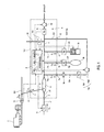
Fig. 1 is a schematic diagram of an exhaust gas measurement system using an exhaust gas dilution device of the present embodiment. -
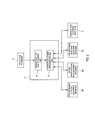
Fig. 2 is a functional configuration diagram of a control device in the same embodiment. -
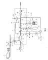
Fig. 3 is a schematic diagram of an exhaust gas measurement system using an exhaust gas dilution device of a modified embodiment. -
Fig. 4 is a schematic diagram of an exhaust gas measurement system using an exhaust gas dilution device of a modified embodiment. -
- 100
- Exhaust gas dilution device
- E
- Internal combustion engine
- EH
- Exhaust pipe
- L1
- Sampling line
- L3a to L3c
- Measurement instrument line
- L2
- Dilution air supply line (dilution gas supply line)
- 2
- Sampling port
- 3
- Dilution air supply port (dilution gas supply port)
- 4
- Diluter
- 5
- Main flow path
- 6
- Main flow rate adjustment mechanism
- 7a to 7c
- Measurement instrument port
- 8
- Control device
- 81
- Exhaust gas flow rate acquisition part
- 82
- Flow rate adjustment mechanism control part
- 9a to 9c
- Measurement instrument
- 10a to 10c
- Branching flow rate adjustment mechanism
- The following describes an exhaust
gas dilution device 100 according to the present invention with reference to drawings. - The exhaust
gas dilution device 100 according to the present embodiment is, for example, a portable one that samples a part of engine exhaust gas (simply referred to as "exhaust gas" hereinafter) flowing through an exhaust pipe EH connected to an engine E to be diluted and supplied to a plurality of measurement instruments. - Specifically, as shown in
Fig. 1 , this device includes: a sampling port 2 that is connected with a sampling line L1 which samples a part of exhaust gas flowing through an exhaust pipe EH as sampling gas; a dilution air supply port (dilution gas supply port) 3 that is connected with a dilution air supply line (dilution gas supply line) L2 which supplies dilution air as dilution gas for diluting the sampled exhaust gas; a single diluter 4 that communicates with the sampling port 2 and the dilution air supply port 3 to thereby dilute the sample gas with the dilution air; a main flow path 5 which is connected to the diluter 4 and through which the diluted exhaust gas diluted by the diluter 4 flows; a main flow rate adjustment mechanism 6 that is provided on the main flow path 5 to adjust a flow rate of the diluted exhaust gas flowing through the main flow path 5; a plurality of measurement instrument ports 7a to 7c that are provided in a plurality of branching flow paths 71a to 71c branched from the main flow path 5 and that are connected with measurement instrument lines L3a to L3c which respectively includes measurement instruments 9a to 9c and branching flow rate adjustment mechanisms 10a to 10c; and a control device 8 that controls the main flow rate adjustment mechanism 6 and the plurality of branching flow rate adjustment mechanisms 10a to 10c. - On the dilution air supply line L2 connected to the dilution air supply port 3, there is provided a dilution air flow
rate adjustment mechanism 11 for adjusting a dilution air flow rate flowing through the dilution air supply line L2 to be supplied to the diluter 4. This dilution air flowrate adjustment mechanism 11 is configured of a massflow controller and controlled by thecontrol device 8 to be described later. - The diluter 4 is a dilution tunnel having an upstream side connected with a
first flow path 21 which has thesampling port 2 at one end and having the upstream side connected with asecond flow path 31 which has the dilution air supply port 3 at one end. And the main flow path 5 is connected to a downstream side of the dilution tunnel 4. - In
Fig. 1 , the main flowrate adjustment mechanism 6 provided on the downstream side of the main flow path 5 is configured of amain flowmeter 61 for measuring a diluted exhaust gas flow rate flowing through the main flow path 5 and a revolution numbercontrollable pump 62 provided on the downstream side of themain flowmeter 61. The revolution number of thispump 62 is controlled by thecontrol device 8 to be described later. Further, this main flowrate adjustment mechanism 6 is connected with a flowrate compensation line 63 for supplying to the main flow path 5 and compensating the flow rates flowing to the second measurement instrument (exhaustgas sampling bag 9b) and the third measurement instrument (exhaust gas analyzer 9c) to be described later. This flowrate compensation line 63 is connected to the upstream side of themain flowmeter 61 and is provided with aflowmeter 631 for measuring a flow rate of compensation air flowing through the flowrate compensation line 63. - The plurality of
measurement instrument ports 7a to 7c include: a firstmeasurement instrument port 7a connected with the first measurement instrument line L3a provided with aPM collecting filter 9a which is a PM measurement instrument for collecting particulate matters (PM) contained in the diluted exhaust gas; a secondmeasurement instrument port 7b connected with the second measurement instrument line L3b provided with an exhaustgas sampling bag 9b which is an exhaust gas measurement instrument for sampling the diluted exhaust gas; and a thirdmeasurement instrument port 7c connected with the third measurement instrument line L3c provided with anexhaust gas analyzer 9c for continuously measuring various components contained in the diluted exhaust gas. - The first measurement instrument line L3a is provided with the first branching flow
rate adjustment mechanism 10a on the downstream side of thePM collecting filter 9a. The first branching flowrate adjustment mechanism 10a of the present embodiment is configured of a first flowmeter 10a1 for measuring a flow rate of the diluted exhaust gas flowing through the first measurement instrument line L3a and a revolution number controllable first pump 10a2 provided on the downstream side of the first flowmeter 10a1. The revolution number of this first pump 10a2 is controlled by thecontrol device 8 to be described later. Thus, the flow rate of the diluted exhaust gas flowing through the first measurement instrument line L3a is adjusted. Note that a lower end portion of this first measurement instrument line L3a is connected to the main flow path 5. That is, the downstream side of the first measurement instrument line L3a is connected to aconnection port 12 for connecting the downstream side of the first measurement instrument line L3a to the main flow path 5. A connectioninternal flow path 121 having thisconnection port 12 at one end is confluent with the main flow path 5 on the upstream side of themain flowmeter 61 of the main flowrate adjustment mechanism 6. - The second measurement instrument line L3b is provided with the branching flow
rate adjustment mechanism 10b such as a massflow controller for adjusting a flow rate of the diluted exhaust gas flowing through the second measurement instrument line L3b, on the upstream side of the exhaustgas sampling bag 9b. This branching flowrate adjustment mechanism 10b is controlled by thecontrol device 8 to be described later. Thus, the flow rate of the diluted exhaust gas flowing through the second measurement instrument line L3b is adjusted. - The third measurement instrument line L3c is provided with the third flowmeter 10c1 for measuring the flow rate of the diluted exhaust gas flowing through the third measurement instrument line L3c, on the upstream side of the
exhaust gas analyzer 9c. And by controlling a pump (not shown) provided inside theexhaust gas analyzer 9c by thecontrol device 8 to be described later, the flow rate of the diluted exhaust gas flowing through the third measurement instrument line L3c is adjusted. That is, the branching flowrate adjustment mechanism 10c is configured of the third flowmeter 10c1 and the pump of theexhaust gas analyzer 9c. - The
control device 8 controls the main flowrate adjustment mechanism 6, the branching flowrate adjustment mechanisms 10a to 10c and a dilution air flowrate adjustment mechanism 11 based on the flow rate of the exhaust gas flowing through the exhaust pipe EH so as to be a proportional sampling by a predetermined dilution ratio and a diversion ratio. In specific, thiscontrol device 8 is a general-purpose and dedicated computer provided with a CPU, a memory, an I/O interface, an AD converter and the like, and by rendering the CPU, peripherals and the like to be in cooperation in accordance with a predetermined program stored in a predetermined area of the memory, there exhibits functions as an exhaust gas flowrate acquisition part 81, a flow rate adjustmentmechanism control part 82 and the like, as shown inFig. 2 . - The exhaust gas flow
rate acquisition part 81 acquires an exhaust gas flow rate related signal which is a measurement signal directly indicating an exhaust gas flow rate from anexhaust gas flowmeter 13 which is provided on the exhaust pipe EH to measure an exhaust gas flow rate QA flowing through the exhaust pipe EH. Then, the exhaust gas flowrate acquisition part 81 outputs the exhaust gas flow rate related signal acquired from theexhaust gas flowmeter 13 to the flow rate adjustmentmechanism control part 82. Note that, as theexhaust gas flowmeter 13, a thermal type flowmeter, a pitot-tube type flowmeter, a differential pressure type flowmeter, an ultrasonic type flow meter and the like are available. In addition, the exhaust gas flowrate acquisition part 81 may also acquire an exhaust gas flow rate related signal indirectly indicating an exhaust gas flow rate QA flowing through the exhaust pipe EH. Note that, as the exhaust gas flow rate related signal indirectly indicating the exhaust gas flow rate QA, there may be considered such as an air-fuel ratio (A/F) of an engine. - The flow rate adjustment
mechanism control part 82 acquires the exhaust gas flow rate related signal to calculate the exhaust gas flow rate QA indicated by the exhaust gas flow rate related signal and controls the main flowrate adjustment mechanism 6 and the branching flowrate adjustment mechanisms 10a to 10c using the exhaust gas flow rate QA as follows.. Note that, in the present embodiment, by controlling the dilution air flowrate adjustment mechanism 11 by thecontrol device 8, a dilution air flow rate QC is adjusted so as to make the dilution ratio in the diluter 4 constant. - In specific, the flow rate adjustment
mechanism control part 82 controls the main flowrate adjustment mechanism 6 based on the exhaust gas flow rate QA and makes a ratio (QB / QA) constant between the exhaust gas flow rate QA flowing through the exhaust pipe EH and the sampling flow rate QB flowing through the sampling line L1. Further, the flow rate adjustmentmechanism control part 82 controls the first and second branching flowrate adjustment mechanisms rate adjustment mechanism 10c is controlled so that a diluted gas flow rate QF flowing through the third measurement instrument line L3c becomes a sample gas flow rate measurable with a predetermined precision in theexhaust gas analyzer 9c. - Thus, by controlling the main flow
rate adjustment mechanism 6 and the branching flowrate adjustment mechanisms 10 and 10b, the dilution ratio of the diluted exhaust gas flowing through the first to third measurement instrument lines L3a to L3c becomes (QB / (QB + QC)). Note that, the diversion ratio of the diluted exhaust gas flowing through the first measurement instrument line L3a becomes (QB / QA × QD/ (QB+ QC)), the diversion ratio of the diluted exhaust gas flowing through the second measurement instrument line L3b becomes (QB / QA × QE / (QB + QC)), and the diversion ratio of the diluted exhaust gas flowing through the third measurement instrument line L3c becomes (QB / QA × QF / (QB + QC)). At this time, it is desirable in view of making the branch ratio constant that, by controlling the branching flowrate adjustment mechanisms mechanism control part 82, the ratio between any two of the diluted exhaust gas flow rates flowing through the first to third measurement instrument lines L3a to L3c is made constant. - According to the exhaust
gas dilution device 100 according to the present embodiment configured as escribed above, by supplying the diluted exhaust gas to the plurality ofmeasurement instruments 9a to 9c including the PM measurement instrument and the exhaust gas measurement instrument from the main flow path 5 through which the diluted exhaust gas diluted by the diluter 4 flows, via the branchingflow paths 71a to 71c, the diluted exhaust gas can be supplied to the plurality ofmeasurement instruments 9a to 9c including the PM measurement instrument and the exhaust gas measurement instrument by a single exhaustgas dilution device 100. At this time, by controlling the main flowrate adjustment mechanism 6 and the branching flowrate adjustment mechanisms control device 8, the dilution ratio and the diversion ratio of the diluted exhaust gas flowing through therespective measurement instruments gas dilution device 100 can be reduced in size, and since it is not necessary to prepare a dilution sampling device for each of themeasurement instruments 9a to 9c, the cost can be also reduced. - Further, since the exhaust gas diluted by a single exhaust
gas dilution device 100 can be supplied to the plurality ofmeasurement instruments 9a to 9c including the PM measurement instrument and the exhaust gas measurement instrument, the exhaust gas diluted with the same exhaust gas under the same dilution condition can be measured, and in the case where measurement results of the plurality ofmeasurement instruments 9a to 9c including the PM measurement instrument and the exhaust gas measurement instrument are compared, the reliability of the comparison results thereof can be improved. - In addition, since the diluted exhaust gas to be supplied to the plurality of
measurement instruments 9a to 9c including the PM measurement instrument and the exhaust gas measurement instrument is produced by a single exhaustgas dilution device 100, there is also an effect that it is easy to incorporate an application such as switching a sampling ON/OFF in synchronization with stopping and starting of an engine and switching a sampling ON/OFF by confirming a concentration of a prescribed component of the exhaust gas. Further, it is sufficient only to confirm an operation of a single exhaustgas dilution device 100, and therefore a maintenance work can be also facilitated. Further, in the present embodiment, since the measurement instrument lines L3a to L3c including themeasurement instruments 9a to 9c and the branching flowrate adjustment mechanisms 10a to 10c are configured so as to be connected to the exhaustgas dilution device 100, it is not necessary to provide a branching flow rate adjustment mechanism in the exhaustgas dilution device 100, and therefore the exhaustgas dilution device 100 can be reduced in size. Further, since the exhaustgas dilution device 100 includes thesample gas port 2, the dilution air supply port 3, the plurality ofmeasurement instrument ports 7a to 7c and the like, each line may be only connected after setting in a predetermined place, it can be appropriately used as a portable one. In addition, although a dilution ratio, a retention time and a temperature range inside the diluter 4 are defined by a recent exhaust gas testing restriction, since the same sampling conditions can be made irrespective of an engine size in the present method, a setting can be made in conformity with the exhaust gas testing restriction irrespective of the engine size. - Note that the present invention should not be limited to the above embodiment.
- For example, the flow rate adjustment
mechanism control part 82 of the embodiment may be configured so as to control the main flowrate adjustment mechanism 6 and the branching flowrate adjustment mechanisms mechanism control part 82 controls the main flowrate adjustment mechanism 6 and makes a ratio (QB / QA) constant between the exhaust gas flow rate QA flowing through the exhaust pipe EH and the sampling flow rate QB flowing through the sampling line L1. Further, the flow rate adjustmentmechanism control part 82 may control the first and second branching flowrate adjustment mechanisms - Also, the flow rate adjustment
mechanism control part 82 may control the main flowrate adjustment mechanism 6 to make the sampling flow rate QB flowing through the sampling line L1 constant, and control the first and second branching flowrate adjustment mechanisms - Further, in view of making only the branch ratio constant, it is sufficient that the flow rate adjustment
mechanism control part 82 controls the main flowrate adjustment mechanism 6 and makes a ratio (QB / QA) constant between the exhaust gas flow rate QA flowing through the exhaust pipe EH and the sampling flow rate QB flowing through the sampling line L1. - Further, the dilution air flow rate flowing through the dilution air supply line L2 may be adjusted to be a constant flow rate by the dilution air flow
rate adjustment mechanism 11. - Further, although the main flow
rate adjustment mechanism 6 of the above embodiment includes themain flowmeter 61, a variablecapacity type pump 62 and the flowrate compensation line 63 including aflowmeter 631, it may include a constantflow rate regulator 64 such as a critical flow rate venture (CFV), aconstant capacity pump 65 and a flowrate compensation line 66 including a flowrate adjustment mechanism 661, as shown inFig. 3 . Further, the dilution air flowrate adjustment mechanism 11 provided on the dilution air supply line L2 may be a constant flow rate regulator such as a critical flow rate venture (CFV). - Further, in the embodiment, although the first, second and third branching flow
rate adjustment mechanisms 10a to 10c provided on the first, second and third measurement instrument lines L3a to L3c are provided outside the exhaustgas dilution device 100, the first, second and third branching flowrate adjustment mechanisms 10a to 10c may be provided on respective branchingflow paths 71a to 71c inside thedevice 100, as shown inFig. 4 . Similarly, as shown inFig. 4 , the dilution air flowrate adjustment mechanism 11 provided on the dilution air supply line L2 may be provided on asecond flow path 31 between the dilution air supply port 3 and the diluter 4. - In addition, the first, second and third measurement instrument lines L3a to L3c should not be limited to three as in the embodiment, and these lines may be three or more. Further, as a kind of the
measurement instruments 9a to 9c, it may only be a measurement instrument measurable using diluted exhaust gas, and it may be, for example, a solid particle number measurement device (SPCS) using a laser scattering condensed particle counter (CPC), a gas absorption bottle (impinge), and the like. - In addition, it is needless to say that the present invention should not be limited to the above embodiments and various modifications thereof can be made in a range without departing from the spirit thereof.
- According to the exhaust gas dilution device of the present invention, by supplying diluted exhaust gas to a plurality of measurement instruments by a single exhaust gas dilution device, the exhaust gas measurement system incorporated with the exhaust gas dilution device can be reduced in size, and the exhaust gas diluted with the same exhaust gas under the same dilution condition can be measured in a plurality of measurement instruments.
Claims (12)
- An exhaust gas dilution device comprising:a sampling port which is connected with a sampling line for sampling, as sample gas, a part of exhaust gas flowing through an exhaust pipe which is connected with an internal combustion engine;a dilution gas supply port which is connected with a dilution gas supply line for supplying dilution gas for diluting sampled exhaust gas;a diluter communicating with the sampling port and the dilution gas supply port to thereby dilute the sample gas with the dilution gas;a main flow path which is connected with the diluter and through which the diluted exhaust gas diluted by the diluter flows;a plurality of measurement instrument ports which are provided in a plurality of branching flow paths branched from the main flow path and which are connected with measurement instrument lines, each of the measurement instrument lines having any one of measurement instruments including a PM measurement instrument and an exhaust gas measurement instrument;a plurality of branching flow rate adjustment mechanisms for adjusting a flow rate of the diluted exhaust gas flowing through each of the branching flow paths; anda control device for controlling the plurality of branching flow rate adjusting mechanisms, whereinthe control device includes:an exhaust gas flow rate acquisition part for acquiring an exhaust gas flow rate related signal that directly or indirectly indicates an exhaust gas flow rate flowing through the exhaust pipe; anda flow rate adjustment mechanism control part for controlling the plurality of branching flow rate adjusting mechanisms using, as a parameter, the exhaust gas flow rate indicated by the exhaust gas flow rate related signal acquired by the exhaust gas flow rate acquisition part and adjusting the diluted exhaust gas flow rates flowing through the plurality of measurement instrument lines.
- The exhaust gas dilution device according to claim 1 further comprising a main flow rate adjustment mechanism provided in the main flow path to adjust the flow rate of the diluted exhaust gas flowing through the main flow path, wherein
the flow rate adjustment mechanism control part controls the main flow rate adjustment mechanism or the plurality of branching flow rate adjustment mechanism using, as the parameter, the exhaust gas flow rate indicated by the exhaust gas flow rate related signal acquired by the exhaust gas flow rate acquisition part to thereby adjust the diluted exhaust gas flow rate flowing through the plurality of measurement instrument lines. - The exhaust gas dilution device according to claim 2, wherein the flow rate adjustment mechanism control part controls the main flow rate adjustment mechanism to thereby make a ratio constant between the exhaust gas flow rate flowing through the exhaust pipe and the sampling flow rate flowing through the sampling line.
- The exhaust gas dilution device according to claim 2, wherein the flow rate adjustment mechanism control part controls the main flow rate adjustment mechanism to thereby make a ratio constant between the exhaust gas flow rate flowing through the exhaust pipe and the sampling flow rate flowing through the sampling line and controls the plurality of branching flow rate adjustment mechanisms to thereby make a ratio constant between the exhaust gas flow rate flowing through the exhaust pipe and the diluted exhaust gas flow rate flowing through each of the measurement instrument lines.
- The exhaust gas dilution device according to claim 3, wherein the flow rate adjustment mechanism control part controls the plurality of branching flow rate control mechanisms to thereby make a ratio constant between any two of the diluted exhaust gas flow rates flowing through the respective measurement instrument lines.
- The exhaust gas dilution device according to claim 1 that is portable.
- An exhaust gas dilution device comprising:a sampling port which is connected with a sampling line for sampling, as sample gas, a part of exhaust gas flowing through an exhaust pipe which is connected with an internal combustion engine;a dilution gas supply port which is connected with a dilution gas supply line for supplying dilution gas for diluting sampled exhaust gas;a diluter communicating with the sampling port and the dilution gas supply port to thereby dilute the sample gas with the dilution gas;a main flow path which is connected with the diluter and through which the diluted exhaust gas diluted by the diluter flows;a plurality of measurement instrument ports which are provided in a plurality of branching flow paths branched from the main flow path and which are connected with measurement instrument lines, each of the measurement instrument lines having any one of measurement instruments including a PM measurement instrument and an exhaust gas measurement instrument and a branching flow rate adjustment mechanism; anda control device for controlling the plurality of branching flow rate adjusting mechanisms, whereinthe control device includes:an exhaust gas flow rate acquisition part for acquiring an exhaust gas flow rate related signal that directly or indirectly indicates an exhaust gas flow rate flowing through the exhaust pipe; anda flow rate adjustment mechanism control part for controlling the plurality of branching flow rate adjusting mechanisms using, as a parameter, the exhaust gas flow rate indicated by the exhaust gas flow rate related signal acquired by the exhaust gas flow rate acquisition part and adjusting the diluted exhaust gas flow rates flowing through the plurality of measurement instrument lines.
- The exhaust gas dilution device according to claim 7 further comprising a main flow rate adjustment mechanism provided in the main flow path to adjust the flow rate of the diluted exhaust gas flowing through the main flow path, wherein
the flow rate adjustment mechanism control part controls the main flow rate adjustment mechanism or the plurality of branching flow rate adjustment mechanism using, as the parameter, the exhaust gas flow rate indicated by the exhaust gas flow rate related signal acquired by the exhaust gas flow rate acquisition part to thereby adjust the diluted exhaust gas flow rate flowing through the plurality of measurement instrument lines. - The exhaust gas dilution device according to claim 8, wherein the flow rate adjustment mechanism control part controls the main flow rate adjustment mechanism to thereby make a ratio constant between the exhaust gas flow rate flowing through the exhaust pipe and the sampling flow rate flowing through the sampling line.
- The exhaust gas dilution device according to claim 8, wherein the flow rate adjustment mechanism control part controls the main flow rate adjustment mechanism to thereby make a ratio between the exhaust gas flow rate flowing through the exhaust pipe and the sampling flow rate flowing through the sampling line constant and controls the plurality of branching flow rate adjustment mechanisms to thereby make a ratio constant between the exhaust gas flow rate flowing through the exhaust pipe and the diluted exhaust gas flow rate flowing through each of the measurement instrument lines.
- The exhaust gas dilution device according to claim 9, wherein the flow rate adjustment mechanism control part controls the plurality of branching flow rate control mechanisms to thereby make a ratio constant between any two of the diluted exhaust gas flow rates flowing through the respective measurement instrument lines.
- The exhaust gas dilution device according to claim 7 that is portable.
Applications Claiming Priority (2)
| Application Number | Priority Date | Filing Date | Title |
|---|---|---|---|
| JP2012126046 | 2012-06-01 | ||
| PCT/JP2013/061398 WO2013179794A1 (en) | 2012-06-01 | 2013-04-17 | Exhaust gas dilution device |
Publications (2)
| Publication Number | Publication Date |
|---|---|
| EP2857823A1 true EP2857823A1 (en) | 2015-04-08 |
| EP2857823A4 EP2857823A4 (en) | 2016-02-24 |
Family
ID=49673001
Family Applications (1)
| Application Number | Title | Priority Date | Filing Date |
|---|---|---|---|
| EP13797667.6A Withdrawn EP2857823A4 (en) | 2012-06-01 | 2013-04-17 | DEVICE FOR DILIVING EXHAUST GASES |
Country Status (6)
| Country | Link |
|---|---|
| US (1) | US10156500B2 (en) |
| EP (1) | EP2857823A4 (en) |
| JP (1) | JP6173309B2 (en) |
| CN (1) | CN104364630A (en) |
| IN (1) | IN2014DN10967A (en) |
| WO (1) | WO2013179794A1 (en) |
Families Citing this family (13)
| Publication number | Priority date | Publication date | Assignee | Title |
|---|---|---|---|---|
| DE102015100567B3 (en) * | 2015-01-15 | 2015-12-10 | Avl Emission Test Systems Gmbh | Exhaust gas sampling system and method of operating such an exhaust sampling system |
| JP6530208B2 (en) * | 2015-03-20 | 2019-06-12 | 株式会社堀場製作所 | Exhaust gas sampling system |
| JP6646476B2 (en) | 2015-04-30 | 2020-02-14 | 株式会社堀場製作所 | Exhaust gas measuring device and exhaust gas measuring method |
| US10371605B2 (en) * | 2015-10-22 | 2019-08-06 | Colorado School Of Mines | Pneumatic mine dust sampling instrument |
| CN105716912B (en) * | 2016-02-01 | 2018-10-09 | 江苏大学 | A kind of adjustable burning gases sampling apparatus of diesel engine instantaneous phase and method |
| JP6646520B2 (en) * | 2016-05-24 | 2020-02-14 | 株式会社堀場製作所 | Exhaust gas analysis system, exhaust gas analysis system program, and exhaust gas analysis method |
| CN108008082B (en) * | 2017-12-21 | 2023-11-10 | 中冶长天国际工程有限责任公司 | A salt-containing gas or SRG gas detection system, analysis tower system and salt-containing gas or SRG gas detection method |
| JP6956002B2 (en) * | 2017-12-27 | 2021-10-27 | 株式会社堀場製作所 | Exhaust gas sampling device, exhaust gas analysis system, exhaust gas sampling method, and exhaust gas sampling program |
| CN108535066A (en) * | 2018-05-24 | 2018-09-14 | 北京全华环保技术标准研究中心 | A kind of detection sampling platform of the civilian Discharged form Coal Combustion factor |
| FI128288B (en) | 2019-02-18 | 2020-02-28 | Dekati Oy | Diluting device for aerosol measurements |
| CN110579379B (en) * | 2019-09-26 | 2021-11-09 | 同济大学 | Motor vehicle tail gas flexible sampling system and sampling method |
| CN111024571A (en) * | 2019-12-10 | 2020-04-17 | 北京雪迪龙科技股份有限公司 | Sampling flow control system for particulate matter monitor, particulate matter monitor, method and device for controlling gas flow |
| KR102569612B1 (en) * | 2021-07-20 | 2023-08-25 | 한국기계연구원 | Apparatus for diluting exhaust gas |
Family Cites Families (22)
| Publication number | Priority date | Publication date | Assignee | Title |
|---|---|---|---|---|
| US4586367A (en) * | 1984-03-19 | 1986-05-06 | Horiba Instruments Incorporated | Proportional exhaust sampler and control means |
| JPS6210639U (en) * | 1985-07-05 | 1987-01-22 | ||
| JPS6338036U (en) * | 1986-08-29 | 1988-03-11 | ||
| JP2739491B2 (en) * | 1989-02-15 | 1998-04-15 | 日野自動車工業株式会社 | Exhaust gas measurement device |
| JP2596718Y2 (en) * | 1993-06-22 | 1999-06-21 | 日産ディーゼル工業株式会社 | Split-flow dilution flue gas measuring device |
| DE4437739A1 (en) * | 1994-10-21 | 1996-04-25 | Siemens Ag | Method and arrangement for treating exhaust gas, in particular internal combustion engines for analysis |
| JP3201506B2 (en) | 1995-02-21 | 2001-08-20 | 株式会社堀場製作所 | Gas sampling equipment |
| JP3628126B2 (en) * | 1996-10-25 | 2005-03-09 | 株式会社小野測器 | Extraction device and dilution device |
| JP3374077B2 (en) | 1998-05-12 | 2003-02-04 | 株式会社堀場製作所 | Exhaust gas sampling device |
| US6151952A (en) * | 1998-10-26 | 2000-11-28 | California Analytical Instruments, Inc. | System for mass emission sampling of combustion products |
| JP3629165B2 (en) * | 1999-05-28 | 2005-03-16 | 株式会社堀場製作所 | Recording medium for recording automobile exhaust gas collection program, automobile exhaust gas collection method, and automobile exhaust gas collection apparatus |
| JP4246867B2 (en) * | 1999-12-06 | 2009-04-02 | 株式会社堀場製作所 | Exhaust gas analysis system |
| ATE330221T1 (en) | 2000-05-25 | 2006-07-15 | Her Majesty The Queen In The R | DEVICE AND METHOD FOR EMISSION SAMPLING |
| JP4447266B2 (en) * | 2003-08-18 | 2010-04-07 | 株式会社堀場製作所 | Exhaust gas flow measuring device and exhaust gas measuring system using the same |
| US7124621B2 (en) | 2004-07-21 | 2006-10-24 | Horiba Instruments, Inc. | Acoustic flowmeter calibration method |
| WO2006012433A2 (en) * | 2004-07-21 | 2006-02-02 | Sensors, Inc. | Fast operating dilution flow control system and method for sampling exhaust analysis |
| JP4544978B2 (en) * | 2004-11-30 | 2010-09-15 | 株式会社堀場製作所 | Exhaust gas analyzer and soot measurement method |
| JP4652786B2 (en) * | 2004-11-30 | 2011-03-16 | 株式会社堀場製作所 | Exhaust gas analyzer and mixing system |
| JP2008157682A (en) * | 2006-12-21 | 2008-07-10 | Horiba Ltd | Exhaust gas measuring bag |
| US8280645B2 (en) * | 2008-05-16 | 2012-10-02 | Horiba, Ltd. | Method and apparatus of measuring particulate matters |
| US8505395B2 (en) * | 2009-08-25 | 2013-08-13 | Caterpillar Inc. | Dilution system test apparatus with added capability and method of operating same |
| JP5837415B2 (en) * | 2011-01-12 | 2015-12-24 | 株式会社堀場製作所 | Characteristic measurement method of critical orifice type constant flow device used for multistage dilution mechanism. |
-
2013
- 2013-04-17 IN IN10967DEN2014 patent/IN2014DN10967A/en unknown
- 2013-04-17 EP EP13797667.6A patent/EP2857823A4/en not_active Withdrawn
- 2013-04-17 JP JP2014518336A patent/JP6173309B2/en not_active Expired - Fee Related
- 2013-04-17 WO PCT/JP2013/061398 patent/WO2013179794A1/en not_active Ceased
- 2013-04-17 US US14/404,840 patent/US10156500B2/en not_active Expired - Fee Related
- 2013-04-17 CN CN201380028860.XA patent/CN104364630A/en active Pending
Also Published As
| Publication number | Publication date |
|---|---|
| US10156500B2 (en) | 2018-12-18 |
| EP2857823A4 (en) | 2016-02-24 |
| JPWO2013179794A1 (en) | 2016-01-18 |
| CN104364630A (en) | 2015-02-18 |
| JP6173309B2 (en) | 2017-08-02 |
| IN2014DN10967A (en) | 2015-09-18 |
| US20150153255A1 (en) | 2015-06-04 |
| WO2013179794A1 (en) | 2013-12-05 |
Similar Documents
| Publication | Publication Date | Title |
|---|---|---|
| US10156500B2 (en) | Exhaust gas dilution device | |
| EP2410326B1 (en) | Exhaust gas analyzing system | |
| EP2772744B1 (en) | Exhaust gas sampling apparatus | |
| EP2515095A1 (en) | Exhaust gas sampling device | |
| EP3088861B1 (en) | Exhaust gas measurement system and method | |
| EP2775284B1 (en) | Exhaust gas sampling apparatus | |
| US6370936B1 (en) | Sampling apparatus for exhaust gas | |
| EP1106983A2 (en) | Exhaust gas analyzing system | |
| CN108226387B (en) | Vehicle-mounted exhaust gas analysis system, inspection method thereof, storage medium, and inspection system | |
| CN101680821A (en) | Exhaust gas sampling diluter and method | |
| JP2019530862A (en) | Passive aerosol dilutor mechanism | |
| EP3505904A1 (en) | Exhaust gas sampling apparatus and method having a flow rate changeable mechanism | |
| EP2477023B1 (en) | Method of measuring characteristics of critical orifice type constant flow rate instrument for use in multistage dilution mechanism | |
| CN110068487B (en) | Exhaust gas dilution device and PM measurement system | |
| EP3470816A1 (en) | Exhaust gas analysis apparatus, exhaust gas analysis system, exhaust gas measurement method, program for exhaust gas analysis apparatus, and calibration method for exhaust gas analysis apparatus | |
| JP6446322B2 (en) | Verification system | |
| EP2778651A2 (en) | Exhaust gas analyzing apparatus | |
| CN108426848B (en) | Dilution error detection device and method of standard gas dilution device based on infrared gas analyzer | |
| WO2007041274A2 (en) | Sampler for engine exhaust dilution | |
| US7565846B2 (en) | Particulate sampler and dilution gas flow device arrangement for an exhaust sampling system | |
| US20090094950A1 (en) | Calibration unit for volatile particle remover | |
| US20130276552A1 (en) | Raw proportional toxic sampler for sampling exhaust | |
| EP3499214A1 (en) | Exhaust gas analysis system and exhaust gas analysis method | |
| JP2001264223A (en) | Sampling device for exhaust gas |
Legal Events
| Date | Code | Title | Description |
|---|---|---|---|
| PUAI | Public reference made under article 153(3) epc to a published international application that has entered the european phase |
Free format text: ORIGINAL CODE: 0009012 |
|
| 17P | Request for examination filed |
Effective date: 20141217 |
|
| AK | Designated contracting states |
Kind code of ref document: A1 Designated state(s): AL AT BE BG CH CY CZ DE DK EE ES FI FR GB GR HR HU IE IS IT LI LT LU LV MC MK MT NL NO PL PT RO RS SE SI SK SM TR |
|
| AX | Request for extension of the european patent |
Extension state: BA ME |
|
| DAX | Request for extension of the european patent (deleted) | ||
| RA4 | Supplementary search report drawn up and despatched (corrected) |
Effective date: 20160126 |
|
| RIC1 | Information provided on ipc code assigned before grant |
Ipc: G01N 33/00 20060101ALN20160119BHEP Ipc: G01M 15/10 20060101ALN20160119BHEP Ipc: G01N 1/22 20060101AFI20160119BHEP |
|
| STAA | Information on the status of an ep patent application or granted ep patent |
Free format text: STATUS: EXAMINATION IS IN PROGRESS |
|
| 17Q | First examination report despatched |
Effective date: 20190621 |
|
| STAA | Information on the status of an ep patent application or granted ep patent |
Free format text: STATUS: THE APPLICATION IS DEEMED TO BE WITHDRAWN |
|
| 18D | Application deemed to be withdrawn |
Effective date: 20201103 |