EP2857767B1 - Air conditioner - Google Patents
Air conditioner Download PDFInfo
- Publication number
- EP2857767B1 EP2857767B1 EP13777479.0A EP13777479A EP2857767B1 EP 2857767 B1 EP2857767 B1 EP 2857767B1 EP 13777479 A EP13777479 A EP 13777479A EP 2857767 B1 EP2857767 B1 EP 2857767B1
- Authority
- EP
- European Patent Office
- Prior art keywords
- heat exchanger
- temperature
- air conditioner
- indoor
- dehumidification
- Prior art date
- Legal status (The legal status is an assumption and is not a legal conclusion. Google has not performed a legal analysis and makes no representation as to the accuracy of the status listed.)
- Active
Links
Images


Classifications
-
- F—MECHANICAL ENGINEERING; LIGHTING; HEATING; WEAPONS; BLASTING
- F24—HEATING; RANGES; VENTILATING
- F24F—AIR-CONDITIONING; AIR-HUMIDIFICATION; VENTILATION; USE OF AIR CURRENTS FOR SCREENING
- F24F1/00—Room units for air-conditioning, e.g. separate or self-contained units or units receiving primary air from a central station
- F24F1/0007—Indoor units, e.g. fan coil units
- F24F1/0059—Indoor units, e.g. fan coil units characterised by heat exchangers
- F24F1/0063—Indoor units, e.g. fan coil units characterised by heat exchangers by the mounting or arrangement of the heat exchangers
-
- F—MECHANICAL ENGINEERING; LIGHTING; HEATING; WEAPONS; BLASTING
- F25—REFRIGERATION OR COOLING; COMBINED HEATING AND REFRIGERATION SYSTEMS; HEAT PUMP SYSTEMS; MANUFACTURE OR STORAGE OF ICE; LIQUEFACTION SOLIDIFICATION OF GASES
- F25B—REFRIGERATION MACHINES, PLANTS OR SYSTEMS; COMBINED HEATING AND REFRIGERATION SYSTEMS; HEAT PUMP SYSTEMS
- F25B43/00—Arrangements for separating or purifying gases or liquids; Arrangements for vaporising the residuum of liquid refrigerant, e.g. by heat
-
- F—MECHANICAL ENGINEERING; LIGHTING; HEATING; WEAPONS; BLASTING
- F24—HEATING; RANGES; VENTILATING
- F24F—AIR-CONDITIONING; AIR-HUMIDIFICATION; VENTILATION; USE OF AIR CURRENTS FOR SCREENING
- F24F11/00—Control or safety arrangements
- F24F11/62—Control or safety arrangements characterised by the type of control or by internal processing, e.g. using fuzzy logic, adaptive control or estimation of values
- F24F11/63—Electronic processing
- F24F11/65—Electronic processing for selecting an operating mode
-
- F—MECHANICAL ENGINEERING; LIGHTING; HEATING; WEAPONS; BLASTING
- F25—REFRIGERATION OR COOLING; COMBINED HEATING AND REFRIGERATION SYSTEMS; HEAT PUMP SYSTEMS; MANUFACTURE OR STORAGE OF ICE; LIQUEFACTION SOLIDIFICATION OF GASES
- F25B—REFRIGERATION MACHINES, PLANTS OR SYSTEMS; COMBINED HEATING AND REFRIGERATION SYSTEMS; HEAT PUMP SYSTEMS
- F25B40/00—Subcoolers, desuperheaters or superheaters
- F25B40/02—Subcoolers
-
- F—MECHANICAL ENGINEERING; LIGHTING; HEATING; WEAPONS; BLASTING
- F25—REFRIGERATION OR COOLING; COMBINED HEATING AND REFRIGERATION SYSTEMS; HEAT PUMP SYSTEMS; MANUFACTURE OR STORAGE OF ICE; LIQUEFACTION SOLIDIFICATION OF GASES
- F25B—REFRIGERATION MACHINES, PLANTS OR SYSTEMS; COMBINED HEATING AND REFRIGERATION SYSTEMS; HEAT PUMP SYSTEMS
- F25B49/00—Arrangement or mounting of control or safety devices
- F25B49/02—Arrangement or mounting of control or safety devices for compression type machines, plants or systems
-
- F—MECHANICAL ENGINEERING; LIGHTING; HEATING; WEAPONS; BLASTING
- F24—HEATING; RANGES; VENTILATING
- F24F—AIR-CONDITIONING; AIR-HUMIDIFICATION; VENTILATION; USE OF AIR CURRENTS FOR SCREENING
- F24F1/00—Room units for air-conditioning, e.g. separate or self-contained units or units receiving primary air from a central station
- F24F1/0007—Indoor units, e.g. fan coil units
- F24F1/0059—Indoor units, e.g. fan coil units characterised by heat exchangers
-
- F—MECHANICAL ENGINEERING; LIGHTING; HEATING; WEAPONS; BLASTING
- F24—HEATING; RANGES; VENTILATING
- F24F—AIR-CONDITIONING; AIR-HUMIDIFICATION; VENTILATION; USE OF AIR CURRENTS FOR SCREENING
- F24F1/00—Room units for air-conditioning, e.g. separate or self-contained units or units receiving primary air from a central station
- F24F1/0007—Indoor units, e.g. fan coil units
- F24F1/0068—Indoor units, e.g. fan coil units characterised by the arrangement of refrigerant piping outside the heat exchanger within the unit casing
-
- F—MECHANICAL ENGINEERING; LIGHTING; HEATING; WEAPONS; BLASTING
- F24—HEATING; RANGES; VENTILATING
- F24F—AIR-CONDITIONING; AIR-HUMIDIFICATION; VENTILATION; USE OF AIR CURRENTS FOR SCREENING
- F24F3/00—Air-conditioning systems in which conditioned primary air is supplied from one or more central stations to distributing units in the rooms or spaces where it may receive secondary treatment; Apparatus specially designed for such systems
- F24F3/12—Air-conditioning systems in which conditioned primary air is supplied from one or more central stations to distributing units in the rooms or spaces where it may receive secondary treatment; Apparatus specially designed for such systems characterised by the treatment of the air otherwise than by heating and cooling
- F24F3/14—Air-conditioning systems in which conditioned primary air is supplied from one or more central stations to distributing units in the rooms or spaces where it may receive secondary treatment; Apparatus specially designed for such systems characterised by the treatment of the air otherwise than by heating and cooling by humidification; by dehumidification
- F24F2003/144—Air-conditioning systems in which conditioned primary air is supplied from one or more central stations to distributing units in the rooms or spaces where it may receive secondary treatment; Apparatus specially designed for such systems characterised by the treatment of the air otherwise than by heating and cooling by humidification; by dehumidification by dehumidification only
- F24F2003/1446—Air-conditioning systems in which conditioned primary air is supplied from one or more central stations to distributing units in the rooms or spaces where it may receive secondary treatment; Apparatus specially designed for such systems characterised by the treatment of the air otherwise than by heating and cooling by humidification; by dehumidification by dehumidification only by condensing
-
- F—MECHANICAL ENGINEERING; LIGHTING; HEATING; WEAPONS; BLASTING
- F24—HEATING; RANGES; VENTILATING
- F24F—AIR-CONDITIONING; AIR-HUMIDIFICATION; VENTILATION; USE OF AIR CURRENTS FOR SCREENING
- F24F2140/00—Control inputs relating to system states
- F24F2140/50—Load
-
- F—MECHANICAL ENGINEERING; LIGHTING; HEATING; WEAPONS; BLASTING
- F25—REFRIGERATION OR COOLING; COMBINED HEATING AND REFRIGERATION SYSTEMS; HEAT PUMP SYSTEMS; MANUFACTURE OR STORAGE OF ICE; LIQUEFACTION SOLIDIFICATION OF GASES
- F25B—REFRIGERATION MACHINES, PLANTS OR SYSTEMS; COMBINED HEATING AND REFRIGERATION SYSTEMS; HEAT PUMP SYSTEMS
- F25B13/00—Compression machines, plants or systems, with reversible cycle
-
- F—MECHANICAL ENGINEERING; LIGHTING; HEATING; WEAPONS; BLASTING
- F25—REFRIGERATION OR COOLING; COMBINED HEATING AND REFRIGERATION SYSTEMS; HEAT PUMP SYSTEMS; MANUFACTURE OR STORAGE OF ICE; LIQUEFACTION SOLIDIFICATION OF GASES
- F25B—REFRIGERATION MACHINES, PLANTS OR SYSTEMS; COMBINED HEATING AND REFRIGERATION SYSTEMS; HEAT PUMP SYSTEMS
- F25B2313/00—Compression machines, plants or systems with reversible cycle not otherwise provided for
- F25B2313/023—Compression machines, plants or systems with reversible cycle not otherwise provided for using multiple indoor units
- F25B2313/0234—Compression machines, plants or systems with reversible cycle not otherwise provided for using multiple indoor units in series arrangements
-
- F—MECHANICAL ENGINEERING; LIGHTING; HEATING; WEAPONS; BLASTING
- F25—REFRIGERATION OR COOLING; COMBINED HEATING AND REFRIGERATION SYSTEMS; HEAT PUMP SYSTEMS; MANUFACTURE OR STORAGE OF ICE; LIQUEFACTION SOLIDIFICATION OF GASES
- F25B—REFRIGERATION MACHINES, PLANTS OR SYSTEMS; COMBINED HEATING AND REFRIGERATION SYSTEMS; HEAT PUMP SYSTEMS
- F25B2313/00—Compression machines, plants or systems with reversible cycle not otherwise provided for
- F25B2313/031—Sensor arrangements
- F25B2313/0314—Temperature sensors near the indoor heat exchanger
-
- F—MECHANICAL ENGINEERING; LIGHTING; HEATING; WEAPONS; BLASTING
- F25—REFRIGERATION OR COOLING; COMBINED HEATING AND REFRIGERATION SYSTEMS; HEAT PUMP SYSTEMS; MANUFACTURE OR STORAGE OF ICE; LIQUEFACTION SOLIDIFICATION OF GASES
- F25B—REFRIGERATION MACHINES, PLANTS OR SYSTEMS; COMBINED HEATING AND REFRIGERATION SYSTEMS; HEAT PUMP SYSTEMS
- F25B2313/00—Compression machines, plants or systems with reversible cycle not otherwise provided for
- F25B2313/031—Sensor arrangements
- F25B2313/0315—Temperature sensors near the outdoor heat exchanger
-
- F—MECHANICAL ENGINEERING; LIGHTING; HEATING; WEAPONS; BLASTING
- F25—REFRIGERATION OR COOLING; COMBINED HEATING AND REFRIGERATION SYSTEMS; HEAT PUMP SYSTEMS; MANUFACTURE OR STORAGE OF ICE; LIQUEFACTION SOLIDIFICATION OF GASES
- F25B—REFRIGERATION MACHINES, PLANTS OR SYSTEMS; COMBINED HEATING AND REFRIGERATION SYSTEMS; HEAT PUMP SYSTEMS
- F25B2700/00—Sensing or detecting of parameters; Sensors therefor
- F25B2700/21—Temperatures
- F25B2700/2104—Temperatures of an indoor room or compartment
Definitions
- the present invention relates to an air conditioner configured to perform a dehumidification operation.
- a conventional air conditioner in which: an auxiliary heat exchanger is disposed rearward of a main heat exchanger; and a refrigerant evaporates only in the auxiliary heat exchanger to locally perform dehumidification so that dehumidification can be performed even under a low load (even when the number of revolution of a compressor is small), for example, when the difference between room temperature and a set temperature is sufficiently small and therefore the required cooling capacity is small.
- JP 2012 017889 A describes an air conditioner including a refrigerant circuit connected with a compressor, an outdoor heat exchanger, an outdoor expansion valve, a first indoor expansion valve, and a first indoor heat exchanging section.
- a bypass pipe bypasses the outdoor heat exchanger and outdoor expansion valve.
- the air conditioner is provided with a second indoor heat exchanging section and a second indoor expansion valve in the middle thereof.
- the air conditioner is further provided with a controller.
- the controller performs dehumidification control for controlling the rotational speed of the compressor based on target evaporation temperature which is set based on a difference between the humidity in an air conditioned room and the target humidity and which is a target value of the evaporation temperature of a refrigerant passing through the first indoor heat exchanging section, and performs temperature control for controlling the opening of each of the outdoor expansion valve and second indoor expansion valve based on a difference between temperature in the air conditioned room and the target temperature.
- Patent Literature 1 Japanese Unexamined Patent Publication No. 14727/1997 (Tokukaihei 09-14727)
- this air conditioner employs the method of solely cooling the auxiliary heat exchanger from the start while the indoor temperature is high, the cooling capacity is insufficient and the room temperature is not immediately decreased.
- the COP coefficient of performance therefore deteriorates when the dehumidification operation is performed.
- An object of the present invention is to provide an air conditioner in which the influence of the deterioration of the COP due to the dehumidification operation is minimized.
- an air conditioner includes a refrigerant circuit in which a compressor, an outdoor heat exchanger, an expansion valve, and an indoor heat exchanger are connected to one another, the air conditioner configured to perform a cooling operation in which the entirety of the indoor heat exchanger functions as an evaporation region and a dehumidification operation in which a part of the indoor heat exchanger functions as the evaporation region, wherein, when a load is high at the selection of the dehumidification operation to start driving, the cooling operation is started and then switching to the dehumidification operation is executed in accordance with the decrease in the load.
- the air conditioner of the first aspect is arranged such that, the load is detected based on a difference between an indoor temperature and a set temperature.
- the load is detected based on a difference between an indoor temperature and a set temperature.
- the air conditioner of the first or second aspect is arranged such that the load is detected based on a frequency of the compressor.
- the load is detected based on a frequency of the compressor.
- the air conditioner of any one of the first to third aspects is arranged such that, after the start of a cooling operation, switching to a dehumidification operation is not executed when an evaporation temperature is lower than a predetermined temperature.
- the load when the load is high, sufficient dehumidification is possible even in the cooling operation on account of a low temperature of the heat exchanger. On this account, dehumidification and cooling are efficiently and simultaneously done by starting the cooling operation. As the load decreases with the decrease in the room temperature, the operation is switched to the dehumidification operation since dehumidification in the cooling operation becomes impossible on account of an increased evaporation temperature. In this way, the influence of the deterioration of the COP due to the dehumidification is minimized.
- the load is detected based on a difference between an indoor temperature and a set temperature.
- the load is detected based on a frequency of the compressor.
- the evaporation temperature is lower than the predetermined temperature when the load becomes equal to or lower than a predetermined value, dehumidification is possible without the switching from the cooling operation to the dehumidification operation.
- the air conditioner 1 of this embodiment includes: an indoor unit 2 installed inside a room; and an outdoor unit 3 installed outside the room.
- the air conditioner 1 further includes a refrigerant circuit in which a compressor 10, a four-way valve 11, an outdoor heat exchanger 12, an expansion valve 13, and an indoor heat exchanger 14 are connected to one another.
- the outdoor heat exchanger 12 is connected to a discharge port of the compressor 10 via the four-way valve 11, and the expansion valve 13 is connected to the outdoor heat exchanger 12.
- one end of the indoor heat exchanger 14 is connected to the expansion valve 13, and the other end of the indoor heat exchanger 14 is connected to an intake port of the compressor 10 via the four-way valve 11.
- the indoor heat exchanger 14 includes an auxiliary heat exchanger 20 and a main heat exchanger 21.
- the air conditioner 1 operations in a cooling operation mode, in a predetermined dehumidification operation mode, and in a heating operation mode are possible.
- various operations are possible: selecting one of the operation modes to start the operation, changing the operation mode, stopping the operation, and the like. Further, using the remote controller, it is possible to adjust indoor temperature setting, and to change the air volume of the indoor unit 2 by changing the number of revolutions of an indoor fan.
- a refrigerant discharged from the compressor 10 flows, from the four-way valve 11, through the outdoor heat exchanger 12, the expansion valve 13, and the auxiliary heat exchanger 20, to the main heat exchanger 21 in order; and the refrigerant having passed through the main heat exchanger 21 returns back to the compressor 10 via the four-way valve 11. That is, the outdoor heat exchanger 12 functions as a condenser, and the indoor heat exchanger 14 (the auxiliary heat exchanger 20 and the main heat exchanger 21) functions as an evaporator.
- the state of the four-way valve 11 is switched, to form a heating cycle in which: the refrigerant discharged from the compressor 10 flows, from the four-way valve 11, through the main heat exchanger 21, the auxiliary heat exchanger 20, and the expansion valve 13, to the outdoor heat exchanger 12 in order; and the refrigerant having passed through the outdoor heat exchanger 12 returns back to the compressor 10 via the four-way valve 11, as indicated with broken arrows in the figure. That is, the indoor heat exchanger 14 (the auxiliary heat exchanger 20 and the main heat exchanger 21) functions as a condenser, and the outdoor heat exchanger 12 functions as an evaporator.
- the indoor unit 2 has, on its upper surface, an air inlet 2a through which indoor air is taken in.
- the indoor unit 2 further has, on a lower portion of its front surface, an air outlet 2b through which air for air conditioning comes out.
- an airflow path is formed from the air inlet 2a to the air outlet 2b.
- the indoor heat exchanger 14 and a cross-flow indoor fan 16 are disposed. Therefore, as the indoor fan 16 rotates, the indoor air is taken into the indoor unit 1 through the air inlet 2a.
- the air taken in through the air inlet 2a flows through the auxiliary heat exchanger 20 and the main heat exchanger 21 toward the indoor fan 16. Meanwhile, in a rear portion of the indoor unit 2, the air taken in through the air inlet 2a flows through the main heat exchanger 21 toward the indoor fan 16.
- the indoor heat exchanger 14 includes: the auxiliary heat exchanger 20; and the main heat exchanger 21 located downstream of the auxiliary heat exchanger 20 in an operation in the cooling operation mode or in the predetermined dehumidification operation mode.
- the main heat exchanger 21 includes: a front heat exchanger 21a disposed on a front side of the indoor unit 2; and a rear heat exchanger 21b disposed on a rear side of the indoor unit 2.
- the heat exchangers 21a and 21b are arranged in a shape of a counter-V around the indoor fan 16.
- the auxiliary heat exchanger 20 is disposed forward of the front heat exchanger 21a.
- Each of the auxiliary heat exchanger 20 and the main heat exchanger 21 includes heat exchanger pipes and a plurality of fins.
- a liquid refrigerant is supplied through a liquid inlet 17a provided in the vicinity of a lower end of the auxiliary heat exchanger 20, and the thus supplied liquid refrigerant flows toward an upper end of the auxiliary heat exchanger 20, as shown in FIG. 3 .
- the refrigerant is discharged through an outlet 17b provided in the vicinity of the upper end of the auxiliary heat exchanger 20, and then flows to a branching section 18a.
- the refrigerant is divided at the branching section 18a into branches, which are respectively supplied, via three inlets 17c of the main heat exchanger 21, to a lower portion and an upper portion of the front heat exchanger 21a and to the rear heat exchanger 21b.
- the branched refrigerant is discharged through outlets 17d, to merge together at a merging section 18b.
- the refrigerant flows in a reverse direction of the above direction.
- the liquid refrigerant supplied through the liquid inlet 17a of the auxiliary heat exchanger 20 all evaporates midway in the auxiliary heat exchanger 20, i.e., before reaching the outlet. Therefore, only a partial area in the vicinity of the liquid inlet 17a of the auxiliary heat exchanger 20 is an evaporation region where the liquid refrigerant evaporates.
- only the upstream partial area in the auxiliary heat exchanger 20 is the evaporation region, while (i) the area downstream of the evaporation region in the auxiliary heat exchanger 20 and (ii) the main heat exchanger 21 each functions as a superheat region, in the indoor heat exchanger 14.
- the refrigerant having flowed through the superheat region in the vicinity of the upper end of the auxiliary heat exchanger 20 flows through the lower portion of the front heat exchanger 21a disposed leeward from a lower portion of the auxiliary heat exchanger 20. Therefore, among the air taken in through the air inlet 2a, air having been cooled in the evaporation region of the auxiliary heat exchanger 20 is heated by the front heat exchanger 21a, and then blown out from the air outlet 2b.
- air having flowed through the superheat region of the auxiliary heat exchanger 20 and through the front heat exchanger 21a, and air having flowed through the rear heat exchanger 21b are blown out from the air outlet 2b at a temperature substantially the same as an indoor temperature.
- an evaporation temperature sensor 30 is attached to the outdoor unit 3, as shown in FIG. 1 .
- the evaporation temperature sensor 30 is configured to detect an evaporation temperature and is disposed downstream of the expansion valve 13 in the refrigerant circuit.
- an indoor temperature sensor 31 configured to detect the indoor temperature (the temperature of the air taken in through the air inlet 2a of the indoor unit 2); and an indoor heat exchanger temperature sensor 32 configured to detect whether evaporation of the liquid refrigerant is completed in the auxiliary heat exchanger 20.
- the indoor heat exchanger temperature sensor 32 is disposed in the vicinity of the upper end of the auxiliary heat exchanger 20 and leeward from the auxiliary heat exchanger 20. Further, in the superheat region in the vicinity of the upper end of the auxiliary heat exchanger 20, the air taken in through the air inlet 2a is hardly cooled. Therefore, when the temperature detected by the indoor heat exchanger temperature sensor 32 is substantially the same as the indoor temperature detected by the indoor temperature sensor 31, it is indicated that evaporation is completed midway in the auxiliary heat exchanger 20, and that the area in the vicinity of the upper end of the auxiliary heat exchanger 20 is the superheat region.
- the indoor heat exchanger temperature sensor 32 is provided to a heat-transfer tube in a middle portion of the indoor heat exchanger 14. Thus, in the vicinity of the middle portion of the indoor heat exchanger 14, detected are the condensation temperature in the heating operation and the evaporation temperature in the cooling operation.
- the control unit of the air conditioner 1 is connected with: the compressor 10; the four-way valve 11; the expansion valve 13; a motor 16a for driving the indoor fan 16; the evaporation temperature sensor 30; the indoor temperature sensor 31; and the indoor heat exchanger temperature sensor 32. Therefore, the control unit controls the operation of the air conditioner 1 based on: a command from the remote controller (for the start of the operation, for indoor temperature setting, or the like); the evaporation temperature detected by the evaporation temperature sensor 30; the indoor temperature detected by the indoor temperature sensor 31 (the temperature of the intake air); and a heat exchanger middle temperature detected by the indoor heat exchanger temperature sensor 32.
- the auxiliary heat exchanger 20 includes the evaporation region where the liquid refrigerant evaporates and the superheat region downstream of the evaporation region in the predetermined dehumidification operation mode.
- the compressor 10 and the expansion valve 13 are controlled so that the extent of the evaporation region varies depending on a load.
- the extent varies depending on a load means that the extent varies depending on the quantity of heat supplied to the evaporation region, and the quantity of heat is determined, for example, by the indoor temperature (the temperature of the intake air) and an indoor air volume.
- the load corresponds to a required dehumidification capacity (required cooling capacity), and the load is determined taking into account, for example, the difference between the indoor temperature and the set temperature.
- the compressor 10 is controlled based on the difference between the indoor temperature and the set temperature.
- the difference between the indoor temperature and the set temperature is large, the load is high, and therefore the compressor 10 is controlled so that its frequency increases.
- the difference between the indoor temperature and the set temperature is small, the load is low, and therefore the compressor 10 is controlled so that its frequency decreases.
- the expansion valve 13 is controlled based on the evaporation temperature detected by the evaporation temperature sensor 30. While the frequency of the compressor 10 is controlled as described above, the expansion valve 13 is controlled so that the evaporation temperature falls within a predetermined temperature range (10 to 14 degrees Celsius) close to a target evaporation temperature (12 degrees Celsius) . It is preferable that the predetermined evaporation temperature range is constant, irrespective of the frequency of the compressor 10. However, the predetermined range may be slightly changed with the change of the frequency as long as the predetermined range is substantially constant.
- the compressor 10 and the expansion valve 13 are controlled depending on the load in the predetermined dehumidification operation mode, and thereby changing the extent of the evaporation region of the auxiliary heat exchanger 20, and causing the evaporation temperature to fall within the predetermined temperature range.
- each of the auxiliary heat exchanger 20 and the front heat exchanger 21a has twelve rows of the heat-transfer tubes.
- the number of rows of the tubes functioning as the evaporation region in the auxiliary heat exchanger 20 in the predetermined dehumidification operation mode is not less than a half of the total number of rows of the tubes of the front heat exchanger 21a, it is possible to sufficiently increase the extent of the evaporation region of the auxiliary heat exchanger, and therefore a variation in the load is addressed sufficiently.
- This structure is effective especially under a high load.
- FIG. 5 is a graph showing how the flow rate changes when the opening degree of the expansion valve 13 is changed.
- the opening degree of the expansion valve 13 continuously changes with the number of driving pulses input to the expansion valve 13. As the opening degree decreases, the flow rate of the refrigerant flowing through the expansion valve 13 decreases.
- the expansion valve 13 is fully closed when the opening degree is t0. In the range of the opening degrees t0 to t1, the flow rate increases at a first gradient as the opening degree increases. In the range of the opening degrees t1 to t2, the flow rate increases at a second gradient as the opening degree increases. Note that the first gradient is larger than the second gradient.
- the following will describe an example of control executed so that the extent of the evaporation region of the auxiliary heat exchanger 20 varies.
- the frequency of the compressor 10 is increased and the opening degree of the expansion valve 13 is changed so as to increase.
- the extent of the evaporation region of the auxiliary heat exchanger 20 becomes larger than that of the predetermined size, and this increases the volume of the air actually passing through the evaporation region even when the volume of the air taken into the indoor unit 2 is constant.
- the frequency of the compressor 10 is decreased and the opening degree of the expansion valve 13 is changed so as to decrease. Therefore, the extent of the evaporation region of the auxiliary heat exchanger 20 becomes smaller than that of the predetermined size, and this decreases the volume of the air actually passing through the evaporation region even when the volume of the air taken into the indoor unit 2 is constant.
- the load is detected based on the frequency of the compressor, which changes in accordance with the difference between the indoor temperature and the set temperature. Therefore, when the frequency of the compressor is lower than a predetermined frequency, the air conditioner 1 determines that the load is low and the dehumidification is not possible in the cooling operation on account of a high evaporation temperature.
- the evaporation temperature (either the evaporation temperature detected by the evaporation temperature sensor 30 or the heat exchanger middle temperature detected by the indoor heat exchanger temperature sensor 32) is detected.
- the operation is not switched to the dehumidification operation because sufficient dehumidification is possible even in the cooling operation.
- the dehumidification operation is started in the air conditioner 1 when the frequency of the compressor is lower than the predetermined frequency and the evaporation temperature is higher than the predetermined temperature.
- step S2 when the operation for starting the dehumidification operation is performed on the remote controller (step S1), whether the frequency of the compressor is smaller than the predetermined frequency and the evaporation temperature is higher than the predetermined temperature is determined (step S2).
- the predetermined frequency is the upper limit frequency in the dehumidification operation mode.
- the predetermined temperature is the dehumidification temperature limit in the cooling operation.
- the air conditioner 1 of this embodiment when the load is high at the execution of the operation for starting the dehumidification operation, sufficient dehumidification is possible even in the cooling operation on account of a low temperature of the heat exchanger, and hence dehumidification and cooling are efficiently and simultaneously done by starting the cooling operation.
- the operation is switched to the dehumidification operation since dehumidification in the cooling operation becomes impossible on account of an increased evaporation temperature. In this way, the influence of the deterioration of the COP due to the dehumidification is minimized.
- the switching to the dehumidification operation is not performed when the evaporation temperature is lower than the predetermined temperature. Because in this case the evaporation temperature is lower than the predetermined temperature, dehumidification is possible without the switching from the cooling operation to the dehumidification operation.
- the auxiliary heat exchanger and the main heat exchanger may be formed into a single unit.
- the indoor heat exchanger is formed as a single unit, and a first portion corresponding to the auxiliary heat exchanger is provided on the most windward side of the indoor heat exchanger, and a second portion corresponding to the main heat exchanger is provided leeward from the first portion.
- the above-described embodiment deals with the air conditioner configured to operate in the cooling operation mode, in the predetermined dehumidification operation mode, and in the heating operation mode.
- the present invention may be applied to an air conditioner configured to conduct a dehumidification operation in a dehumidification operation mode other than the predetermined dehumidification operation mode, in addition to the dehumidification operation in the predetermined dehumidification operation mode.
Description
- The present invention relates to an air conditioner configured to perform a dehumidification operation.
- There has been a conventional air conditioner in which: an auxiliary heat exchanger is disposed rearward of a main heat exchanger; and a refrigerant evaporates only in the auxiliary heat exchanger to locally perform dehumidification so that dehumidification can be performed even under a low load (even when the number of revolution of a compressor is small), for example, when the difference between room temperature and a set temperature is sufficiently small and therefore the required cooling capacity is small.
-
JP 2012 017889 A - Patent Literature 1: Japanese Unexamined Patent
Publication No.14727/1997 - When, however, this air conditioner employs the method of solely cooling the auxiliary heat exchanger from the start while the indoor temperature is high, the cooling capacity is insufficient and the room temperature is not immediately decreased.
- The COP (coefficient of performance) therefore deteriorates when the dehumidification operation is performed.
- An object of the present invention is to provide an air conditioner in which the influence of the deterioration of the COP due to the dehumidification operation is minimized.
- According to the first aspect of the invention, an air conditioner includes a refrigerant circuit in which a compressor, an outdoor heat exchanger, an expansion valve, and an indoor heat exchanger are connected to one another, the air conditioner configured to perform a cooling operation in which the entirety of the indoor heat exchanger functions as an evaporation region and a dehumidification operation in which a part of the indoor heat exchanger functions as the evaporation region, wherein, when a load is high at the selection of the dehumidification operation to start driving, the cooling operation is started and then switching to the dehumidification operation is executed in accordance with the decrease in the load.
- In this air conditioner, when the load is high at the execution of the operation for starting the dehumidification operation, sufficient dehumidification is possible even in the cooling operation on account of a low temperature of the heat exchanger, and hence dehumidification and cooling are efficiently and simultaneously done by starting the cooling operation. As the load decreases with the decrease in the room temperature, the operation is switched to the dehumidification operation since dehumidification in the cooling operation becomes impossible on account of an increased evaporation temperature. In this way, the influence of the deterioration of the COP due to the dehumidification is minimized.
- According to the second aspect of the invention, the air conditioner of the first aspect is arranged such that, the load is detected based on a difference between an indoor temperature and a set temperature.
- In this air conditioner, the load is detected based on a difference between an indoor temperature and a set temperature.
- According to the third aspect of the invention, the air conditioner of the first or second aspect is arranged such that the load is detected based on a frequency of the compressor.
- In this air conditioner, the load is detected based on a frequency of the compressor.
- According to the fourth aspect of the invention, the air conditioner of any one of the first to third aspects is arranged such that, after the start of a cooling operation, switching to a dehumidification operation is not executed when an evaporation temperature is lower than a predetermined temperature.
- In this air conditioner, because the evaporation temperature is lower than the predetermined temperature when the load becomes equal to or lower than a predetermined value, dehumidification is possible without the switching from the cooling operation to the dehumidification operation.
- As described above, the following effects are attained by the present invention.
- According to the first aspect of the invention, when the load is high, sufficient dehumidification is possible even in the cooling operation on account of a low temperature of the heat exchanger. On this account, dehumidification and cooling are efficiently and simultaneously done by starting the cooling operation. As the load decreases with the decrease in the room temperature, the operation is switched to the dehumidification operation since dehumidification in the cooling operation becomes impossible on account of an increased evaporation temperature. In this way, the influence of the deterioration of the COP due to the dehumidification is minimized.
- According to the second aspect of the invention, the load is detected based on a difference between an indoor temperature and a set temperature.
- According to the third aspect of the invention, the load is detected based on a frequency of the compressor.
- According to the fourth aspect of the invention, because the evaporation temperature is lower than the predetermined temperature when the load becomes equal to or lower than a predetermined value, dehumidification is possible without the switching from the cooling operation to the dehumidification operation.
-
- [
FIG. 1] FIG. 1 is a circuit diagram showing a refrigerant circuit of an air conditioner of an embodiment of the present invention. - [
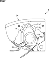
FIG. 2] FIG. 2 is a schematic cross section of an indoor unit of the air conditioner of the embodiment of the present invention. - [
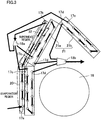
FIG. 3] FIG. 3 is a diagram illustrating the structure of an indoor heat exchanger. - [
FIG. 4] FIG. 4 is a diagram illustrating a control unit of the air conditioner of the embodiment of the present invention. - [
FIG. 5] FIG. 5 is a graph showing, by way of example, how the flow rate changes as the opening degree of an expansion valve is changed. - [
FIG. 6] FIG. 6 illustrates the operation of the air conditioner of the embodiment of the present invention. - The following describes an
air conditioner 1 of an embodiment of the present invention. - As shown in
FIG. 1 , theair conditioner 1 of this embodiment includes: anindoor unit 2 installed inside a room; and anoutdoor unit 3 installed outside the room. Theair conditioner 1 further includes a refrigerant circuit in which acompressor 10, a four-way valve 11, anoutdoor heat exchanger 12, anexpansion valve 13, and anindoor heat exchanger 14 are connected to one another. In the refrigerant circuit, theoutdoor heat exchanger 12 is connected to a discharge port of thecompressor 10 via the four-way valve 11, and theexpansion valve 13 is connected to theoutdoor heat exchanger 12. Further, one end of theindoor heat exchanger 14 is connected to theexpansion valve 13, and the other end of theindoor heat exchanger 14 is connected to an intake port of thecompressor 10 via the four-way valve 11. Theindoor heat exchanger 14 includes anauxiliary heat exchanger 20 and amain heat exchanger 21. - In the
air conditioner 1, operations in a cooling operation mode, in a predetermined dehumidification operation mode, and in a heating operation mode are possible. Using a remote controller, various operations are possible: selecting one of the operation modes to start the operation, changing the operation mode, stopping the operation, and the like. Further, using the remote controller, it is possible to adjust indoor temperature setting, and to change the air volume of theindoor unit 2 by changing the number of revolutions of an indoor fan. - As indicated with solid arrows in the figure, in the cooling operation mode and in the predetermined dehumidification operation mode, there are respectively formed a cooling cycle and a dehumidification cycle, in each of which: a refrigerant discharged from the
compressor 10 flows, from the four-way valve 11, through theoutdoor heat exchanger 12, theexpansion valve 13, and theauxiliary heat exchanger 20, to themain heat exchanger 21 in order; and the refrigerant having passed through themain heat exchanger 21 returns back to thecompressor 10 via the four-way valve 11. That is, theoutdoor heat exchanger 12 functions as a condenser, and the indoor heat exchanger 14 (theauxiliary heat exchanger 20 and the main heat exchanger 21) functions as an evaporator. - Meanwhile, in the heating operation mode, the state of the four-
way valve 11 is switched, to form a heating cycle in which: the refrigerant discharged from thecompressor 10 flows, from the four-way valve 11, through themain heat exchanger 21, theauxiliary heat exchanger 20, and theexpansion valve 13, to theoutdoor heat exchanger 12 in order; and the refrigerant having passed through theoutdoor heat exchanger 12 returns back to thecompressor 10 via the four-way valve 11, as indicated with broken arrows in the figure. That is, the indoor heat exchanger 14 (theauxiliary heat exchanger 20 and the main heat exchanger 21) functions as a condenser, and theoutdoor heat exchanger 12 functions as an evaporator. - The
indoor unit 2 has, on its upper surface, anair inlet 2a through which indoor air is taken in. Theindoor unit 2 further has, on a lower portion of its front surface, anair outlet 2b through which air for air conditioning comes out. Inside theindoor unit 2, an airflow path is formed from theair inlet 2a to theair outlet 2b. In the airflow path, theindoor heat exchanger 14 and a cross-flowindoor fan 16 are disposed. Therefore, as theindoor fan 16 rotates, the indoor air is taken into theindoor unit 1 through theair inlet 2a. In a front portion of theindoor unit 2, the air taken in through theair inlet 2a flows through theauxiliary heat exchanger 20 and themain heat exchanger 21 toward theindoor fan 16. Meanwhile, in a rear portion of theindoor unit 2, the air taken in through theair inlet 2a flows through themain heat exchanger 21 toward theindoor fan 16. - As described above, the
indoor heat exchanger 14 includes: theauxiliary heat exchanger 20; and themain heat exchanger 21 located downstream of theauxiliary heat exchanger 20 in an operation in the cooling operation mode or in the predetermined dehumidification operation mode. Themain heat exchanger 21 includes: afront heat exchanger 21a disposed on a front side of theindoor unit 2; and arear heat exchanger 21b disposed on a rear side of theindoor unit 2. Theheat exchangers indoor fan 16. Further, theauxiliary heat exchanger 20 is disposed forward of thefront heat exchanger 21a. Each of theauxiliary heat exchanger 20 and the main heat exchanger 21 (thefront heat exchanger 21a and therear heat exchanger 21b) includes heat exchanger pipes and a plurality of fins. - In the cooling operation mode and in the predetermined dehumidification operation mode, a liquid refrigerant is supplied through a
liquid inlet 17a provided in the vicinity of a lower end of theauxiliary heat exchanger 20, and the thus supplied liquid refrigerant flows toward an upper end of theauxiliary heat exchanger 20, as shown inFIG. 3 . Then, the refrigerant is discharged through anoutlet 17b provided in the vicinity of the upper end of theauxiliary heat exchanger 20, and then flows to a branchingsection 18a. The refrigerant is divided at the branchingsection 18a into branches, which are respectively supplied, via threeinlets 17c of themain heat exchanger 21, to a lower portion and an upper portion of thefront heat exchanger 21a and to therear heat exchanger 21b. Then, the branched refrigerant is discharged throughoutlets 17d, to merge together at amerging section 18b. In the heating operation mode, the refrigerant flows in a reverse direction of the above direction. - When the
air conditioner 1 operates in the predetermined dehumidification operation mode, the liquid refrigerant supplied through theliquid inlet 17a of theauxiliary heat exchanger 20 all evaporates midway in theauxiliary heat exchanger 20, i.e., before reaching the outlet. Therefore, only a partial area in the vicinity of theliquid inlet 17a of theauxiliary heat exchanger 20 is an evaporation region where the liquid refrigerant evaporates. Accordingly, in the operation in the predetermined dehumidification operation mode, only the upstream partial area in theauxiliary heat exchanger 20 is the evaporation region, while (i) the area downstream of the evaporation region in theauxiliary heat exchanger 20 and (ii) themain heat exchanger 21 each functions as a superheat region, in theindoor heat exchanger 14. - Further, the refrigerant having flowed through the superheat region in the vicinity of the upper end of the
auxiliary heat exchanger 20 flows through the lower portion of thefront heat exchanger 21a disposed leeward from a lower portion of theauxiliary heat exchanger 20. Therefore, among the air taken in through theair inlet 2a, air having been cooled in the evaporation region of theauxiliary heat exchanger 20 is heated by thefront heat exchanger 21a, and then blown out from theair outlet 2b. Meanwhile, among the air taken in through theair inlet 2a, air having flowed through the superheat region of theauxiliary heat exchanger 20 and through thefront heat exchanger 21a, and air having flowed through therear heat exchanger 21b are blown out from theair outlet 2b at a temperature substantially the same as an indoor temperature. - In the
air conditioner 1, anevaporation temperature sensor 30 is attached to theoutdoor unit 3, as shown inFIG. 1 . Theevaporation temperature sensor 30 is configured to detect an evaporation temperature and is disposed downstream of theexpansion valve 13 in the refrigerant circuit. Further, to theindoor unit 2, there are attached: anindoor temperature sensor 31 configured to detect the indoor temperature (the temperature of the air taken in through theair inlet 2a of the indoor unit 2); and an indoor heatexchanger temperature sensor 32 configured to detect whether evaporation of the liquid refrigerant is completed in theauxiliary heat exchanger 20. - As shown in
FIG. 3 , the indoor heatexchanger temperature sensor 32 is disposed in the vicinity of the upper end of theauxiliary heat exchanger 20 and leeward from theauxiliary heat exchanger 20. Further, in the superheat region in the vicinity of the upper end of theauxiliary heat exchanger 20, the air taken in through theair inlet 2a is hardly cooled. Therefore, when the temperature detected by the indoor heatexchanger temperature sensor 32 is substantially the same as the indoor temperature detected by theindoor temperature sensor 31, it is indicated that evaporation is completed midway in theauxiliary heat exchanger 20, and that the area in the vicinity of the upper end of theauxiliary heat exchanger 20 is the superheat region. Furthermore, the indoor heatexchanger temperature sensor 32 is provided to a heat-transfer tube in a middle portion of theindoor heat exchanger 14. Thus, in the vicinity of the middle portion of theindoor heat exchanger 14, detected are the condensation temperature in the heating operation and the evaporation temperature in the cooling operation. - As shown in
FIG. 4 , the control unit of theair conditioner 1 is connected with: thecompressor 10; the four-way valve 11; theexpansion valve 13; amotor 16a for driving theindoor fan 16; theevaporation temperature sensor 30; theindoor temperature sensor 31; and the indoor heatexchanger temperature sensor 32. Therefore, the control unit controls the operation of theair conditioner 1 based on: a command from the remote controller (for the start of the operation, for indoor temperature setting, or the like); the evaporation temperature detected by theevaporation temperature sensor 30; the indoor temperature detected by the indoor temperature sensor 31 (the temperature of the intake air); and a heat exchanger middle temperature detected by the indoor heatexchanger temperature sensor 32. - Further, in the
air conditioner 1, theauxiliary heat exchanger 20 includes the evaporation region where the liquid refrigerant evaporates and the superheat region downstream of the evaporation region in the predetermined dehumidification operation mode. Thecompressor 10 and theexpansion valve 13 are controlled so that the extent of the evaporation region varies depending on a load. Here, "the extent varies depending on a load" means that the extent varies depending on the quantity of heat supplied to the evaporation region, and the quantity of heat is determined, for example, by the indoor temperature (the temperature of the intake air) and an indoor air volume. Further, the load corresponds to a required dehumidification capacity (required cooling capacity), and the load is determined taking into account, for example, the difference between the indoor temperature and the set temperature. - The
compressor 10 is controlled based on the difference between the indoor temperature and the set temperature. When the difference between the indoor temperature and the set temperature is large, the load is high, and therefore thecompressor 10 is controlled so that its frequency increases. When the difference between the indoor temperature and the set temperature is small, the load is low, and therefore thecompressor 10 is controlled so that its frequency decreases. - The
expansion valve 13 is controlled based on the evaporation temperature detected by theevaporation temperature sensor 30. While the frequency of thecompressor 10 is controlled as described above, theexpansion valve 13 is controlled so that the evaporation temperature falls within a predetermined temperature range (10 to 14 degrees Celsius) close to a target evaporation temperature (12 degrees Celsius) . It is preferable that the predetermined evaporation temperature range is constant, irrespective of the frequency of thecompressor 10. However, the predetermined range may be slightly changed with the change of the frequency as long as the predetermined range is substantially constant. - Thus, the
compressor 10 and theexpansion valve 13 are controlled depending on the load in the predetermined dehumidification operation mode, and thereby changing the extent of the evaporation region of theauxiliary heat exchanger 20, and causing the evaporation temperature to fall within the predetermined temperature range. - In the
air conditioner 1, each of theauxiliary heat exchanger 20 and thefront heat exchanger 21a has twelve rows of the heat-transfer tubes. When the number of rows of the tubes functioning as the evaporation region in theauxiliary heat exchanger 20 in the predetermined dehumidification operation mode is not less than a half of the total number of rows of the tubes of thefront heat exchanger 21a, it is possible to sufficiently increase the extent of the evaporation region of the auxiliary heat exchanger, and therefore a variation in the load is addressed sufficiently. This structure is effective especially under a high load. -
FIG. 5 is a graph showing how the flow rate changes when the opening degree of theexpansion valve 13 is changed. The opening degree of theexpansion valve 13 continuously changes with the number of driving pulses input to theexpansion valve 13. As the opening degree decreases, the flow rate of the refrigerant flowing through theexpansion valve 13 decreases. Theexpansion valve 13 is fully closed when the opening degree is t0. In the range of the opening degrees t0 to t1, the flow rate increases at a first gradient as the opening degree increases. In the range of the opening degrees t1 to t2, the flow rate increases at a second gradient as the opening degree increases. Note that the first gradient is larger than the second gradient. - The following will describe an example of control executed so that the extent of the evaporation region of the
auxiliary heat exchanger 20 varies. For example, when the load increases in the predetermined dehumidification operation mode on the condition that the extent of the evaporation region of theauxiliary heat exchanger 20 is of a predetermined size, the frequency of thecompressor 10 is increased and the opening degree of theexpansion valve 13 is changed so as to increase. As a result, the extent of the evaporation region of theauxiliary heat exchanger 20 becomes larger than that of the predetermined size, and this increases the volume of the air actually passing through the evaporation region even when the volume of the air taken into theindoor unit 2 is constant. - Meanwhile, when the load becomes lower in the predetermined dehumidification operation mode on the condition that the extent of the evaporation region of the
auxiliary heat exchanger 20 is of the predetermined size, the frequency of thecompressor 10 is decreased and the opening degree of theexpansion valve 13 is changed so as to decrease. Therefore, the extent of the evaporation region of theauxiliary heat exchanger 20 becomes smaller than that of the predetermined size, and this decreases the volume of the air actually passing through the evaporation region even when the volume of the air taken into theindoor unit 2 is constant. - The following will describe actions when the dehumidification operation is selected on the remote controller of the
air conditioner 1 to start driving (operation for starting the dehumidification operation). In theair conditioner 1, when the load is high at the execution of the operation for starting the dehumidification operation, the cooling operation is started instead of the dehumidification operation, and then the operation is switched to the dehumidification operation in accordance with the decrease in the load. - In the
air conditioner 1, the load is detected based on the frequency of the compressor, which changes in accordance with the difference between the indoor temperature and the set temperature. Therefore, when the frequency of the compressor is lower than a predetermined frequency, theair conditioner 1 determines that the load is low and the dehumidification is not possible in the cooling operation on account of a high evaporation temperature. In this connection, in theair conditioner 1, the evaporation temperature (either the evaporation temperature detected by theevaporation temperature sensor 30 or the heat exchanger middle temperature detected by the indoor heat exchanger temperature sensor 32) is detected. When the detected evaporation temperature is lower than a predetermined temperature, the operation is not switched to the dehumidification operation because sufficient dehumidification is possible even in the cooling operation. To put it differently, the dehumidification operation is started in theair conditioner 1 when the frequency of the compressor is lower than the predetermined frequency and the evaporation temperature is higher than the predetermined temperature. - To begin with, when the operation for starting the dehumidification operation is performed on the remote controller (step S1), whether the frequency of the compressor is smaller than the predetermined frequency and the evaporation temperature is higher than the predetermined temperature is determined (step S2). The predetermined frequency is the upper limit frequency in the dehumidification operation mode. The predetermined temperature is the dehumidification temperature limit in the cooling operation. When the frequency of the compressor is not lower than the predetermined frequency or the evaporation temperature is not lower than the predetermined temperature (step S2: NO), the cooling operation is started (step S3). Then the determination in the step S2 is repeated. In the meanwhile, when in the step S2 the frequency of the compressor is lower than the predetermined frequency and the evaporation temperature is higher than the predetermined temperature (step S2: YES), the dehumidification operation is started (step S4).
- In the
air conditioner 1 of this embodiment, when the load is high at the execution of the operation for starting the dehumidification operation, sufficient dehumidification is possible even in the cooling operation on account of a low temperature of the heat exchanger, and hence dehumidification and cooling are efficiently and simultaneously done by starting the cooling operation. As the load decreases with the decrease in the room temperature, the operation is switched to the dehumidification operation since dehumidification in the cooling operation becomes impossible on account of an increased evaporation temperature. In this way, the influence of the deterioration of the COP due to the dehumidification is minimized. - Furthermore, in the
air conditioner 1 of this embodiment, after the cooling operation is started in response to the operation for starting the dehumidification operation, the switching to the dehumidification operation is not performed when the evaporation temperature is lower than the predetermined temperature. Because in this case the evaporation temperature is lower than the predetermined temperature, dehumidification is possible without the switching from the cooling operation to the dehumidification operation. - While the embodiment of the present invention has been described based on the figures, the scope of the invention is not limited to the above-described embodiment. The scope of the present invention is defined by the appended claims rather than the foregoing description of the embodiment, and various changes and modifications can be made herein without departing from the scope of the claims.
- In the above-described embodiment, the auxiliary heat exchanger and the main heat exchanger may be formed into a single unit. In this case, the indoor heat exchanger is formed as a single unit, and a first portion corresponding to the auxiliary heat exchanger is provided on the most windward side of the indoor heat exchanger, and a second portion corresponding to the main heat exchanger is provided leeward from the first portion.
- Further, the above-described embodiment deals with the air conditioner configured to operate in the cooling operation mode, in the predetermined dehumidification operation mode, and in the heating operation mode. However, the present invention may be applied to an air conditioner configured to conduct a dehumidification operation in a dehumidification operation mode other than the predetermined dehumidification operation mode, in addition to the dehumidification operation in the predetermined dehumidification operation mode.
- The influence of the deterioration of the COP due to the dehumidification operation is minimized when the present invention is employed.
-
- 1
- air conditioner
- 2
- indoor unit
- 3
- outdoor unit
- 10
- compressor
- 12
- outdoor heat exchanger
- 13
- expansion valve
- 14
- indoor heat exchanger
- 16
- indoor fan
- 20
- auxiliary heat exchanger
- 21
- main heat exchanger
Claims (4)
- An air conditioner (1) comprising a refrigerant circuit in which a compressor (10), an outdoor heat exchanger (12), an expansion valve (13), and an indoor heat exchanger (14) are connected to one another, the air conditioner (1) configured to perform a cooling operation in which the entirety of the indoor heat exchanger functions as an evaporation region and a dehumidification operation in which a part of the indoor heat exchanger functions as the evaporation region, and characterized in that
the air conditioner (1) is configured such that when a load is high at the selection of the dehumidification operation to start driving, the cooling operation is started and then switching to the dehumidification operation is executed in accordance with the decrease in the load. - The air conditioner according to claim 1, wherein, the load is detected based on a difference between an indoor temperature and a set temperature.
- The air conditioner according to claim 1 or 2, wherein, the load is detected based on a frequency of the compressor.
- The air conditioner according to any of claims 1 to 3, wherein, after the start of the cooling operation, switching to the dehumidification operation is not executed when an evaporation temperature is lower than a predetermined temperature.
Applications Claiming Priority (2)
| Application Number | Priority Date | Filing Date | Title |
|---|---|---|---|
| JP2012093125A JP5533926B2 (en) | 2012-04-16 | 2012-04-16 | Air conditioner |
| PCT/JP2013/060368 WO2013157405A1 (en) | 2012-04-16 | 2013-04-04 | Air conditioner |
Publications (3)
| Publication Number | Publication Date |
|---|---|
| EP2857767A1 EP2857767A1 (en) | 2015-04-08 |
| EP2857767A4 EP2857767A4 (en) | 2016-03-16 |
| EP2857767B1 true EP2857767B1 (en) | 2017-05-31 |
Family
ID=49383369
Family Applications (1)
| Application Number | Title | Priority Date | Filing Date |
|---|---|---|---|
| EP13777479.0A Active EP2857767B1 (en) | 2012-04-16 | 2013-04-04 | Air conditioner |
Country Status (10)
| Country | Link |
|---|---|
| US (1) | US9513041B2 (en) |
| EP (1) | EP2857767B1 (en) |
| JP (1) | JP5533926B2 (en) |
| CN (1) | CN104246386B (en) |
| AU (1) | AU2013250425B2 (en) |
| BR (1) | BR112014025647B1 (en) |
| ES (1) | ES2628489T3 (en) |
| MY (1) | MY175729A (en) |
| SG (1) | SG11201406662TA (en) |
| WO (1) | WO2013157405A1 (en) |
Families Citing this family (14)
| Publication number | Priority date | Publication date | Assignee | Title |
|---|---|---|---|---|
| US10101091B2 (en) * | 2013-10-25 | 2018-10-16 | Mitsubishi Electric Corporation | Heat exchanger and refrigeration cycle apparatus using the same heat exchanger |
| AU2018390660B2 (en) | 2017-12-18 | 2023-01-05 | Daikin Industries, Ltd. | Refrigeration Cycle Apparatus |
| US11506425B2 (en) | 2017-12-18 | 2022-11-22 | Daikin Industries, Ltd. | Refrigeration cycle apparatus |
| US11906207B2 (en) | 2017-12-18 | 2024-02-20 | Daikin Industries, Ltd. | Refrigeration apparatus |
| US11441819B2 (en) | 2017-12-18 | 2022-09-13 | Daikin Industries, Ltd. | Refrigeration cycle apparatus |
| US11365335B2 (en) | 2017-12-18 | 2022-06-21 | Daikin Industries, Ltd. | Composition comprising refrigerant, use thereof, refrigerating machine having same, and method for operating said refrigerating machine |
| US11493244B2 (en) | 2017-12-18 | 2022-11-08 | Daikin Industries, Ltd. | Air-conditioning unit |
| US11549695B2 (en) | 2017-12-18 | 2023-01-10 | Daikin Industries, Ltd. | Heat exchange unit |
| US11549041B2 (en) | 2017-12-18 | 2023-01-10 | Daikin Industries, Ltd. | Composition containing refrigerant, use of said composition, refrigerator having said composition, and method for operating said refrigerator |
| US11435118B2 (en) | 2017-12-18 | 2022-09-06 | Daikin Industries, Ltd. | Heat source unit and refrigeration cycle apparatus |
| CN113637457A (en) | 2017-12-18 | 2021-11-12 | 大金工业株式会社 | Composition containing refrigerant, use thereof, refrigerator having same, and method for operating refrigerator |
| US11820933B2 (en) | 2017-12-18 | 2023-11-21 | Daikin Industries, Ltd. | Refrigeration cycle apparatus |
| US11441802B2 (en) | 2017-12-18 | 2022-09-13 | Daikin Industries, Ltd. | Air conditioning apparatus |
| CN114659304B (en) * | 2022-03-25 | 2024-03-19 | 青岛海尔空调器有限总公司 | Control method and control system for dehumidification of air conditioner, electronic equipment and storage medium |
Family Cites Families (27)
| Publication number | Priority date | Publication date | Assignee | Title |
|---|---|---|---|---|
| JPS6057142A (en) * | 1983-06-27 | 1985-04-02 | Daikin Ind Ltd | Air conditioner |
| JPS63286642A (en) * | 1987-05-19 | 1988-11-24 | Toshiba Corp | Air-conditioning machine |
| JP3051420B2 (en) * | 1990-03-02 | 2000-06-12 | 株式会社日立製作所 | Air conditioner and method of manufacturing indoor heat exchanger used for the device |
| JP3233447B2 (en) * | 1992-06-02 | 2001-11-26 | 東芝キヤリア株式会社 | Air conditioner |
| JPH0657142A (en) * | 1992-08-07 | 1994-03-01 | Toshiba Silicone Co Ltd | Foamable polysiloxane composition for furmed-in-place gasket |
| US5502970A (en) * | 1995-05-05 | 1996-04-02 | Copeland Corporation | Refrigeration control using fluctuating superheat |
| JPH08320160A (en) * | 1995-05-25 | 1996-12-03 | Sharp Corp | Heat pump type air conditioner |
| JP3410859B2 (en) | 1995-06-28 | 2003-05-26 | 東芝キヤリア株式会社 | Air conditioner |
| JP3823444B2 (en) | 1997-05-22 | 2006-09-20 | 株式会社日立製作所 | Air conditioner |
| JP3622199B2 (en) | 1999-08-31 | 2005-02-23 | マックス株式会社 | Nail supply mechanism for nail nailing machine |
| JP4312894B2 (en) * | 1999-09-09 | 2009-08-12 | 東芝キヤリア株式会社 | Air conditioner indoor unit |
| JP3740637B2 (en) * | 2001-11-16 | 2006-02-01 | 三菱電機株式会社 | Air conditioner |
| JP4068927B2 (en) * | 2002-09-13 | 2008-03-26 | 東芝キヤリア株式会社 | Air conditioner |
| JP2004251537A (en) * | 2003-02-20 | 2004-09-09 | Fujitsu General Ltd | Control process of air conditioner |
| CN1566814A (en) * | 2003-06-24 | 2005-01-19 | 乐金电子(天津)电器有限公司 | Dehumidifying air-conditioner and its control method |
| JP2005273923A (en) * | 2004-03-23 | 2005-10-06 | Hitachi Home & Life Solutions Inc | Air conditioner |
| JP2006170503A (en) * | 2004-12-15 | 2006-06-29 | Hitachi Home & Life Solutions Inc | Air conditioner |
| JP2006177573A (en) * | 2004-12-21 | 2006-07-06 | Matsushita Electric Ind Co Ltd | Air conditioner |
| JP4052319B2 (en) * | 2005-05-24 | 2008-02-27 | ダイキン工業株式会社 | Air conditioning system |
| JP2007010200A (en) * | 2005-06-29 | 2007-01-18 | Hitachi Ltd | Air conditioner and its control method |
| ES2324365T3 (en) * | 2005-10-11 | 2009-08-05 | Fujitsu General Limited | AIR CONDITIONER. |
| JP2007240059A (en) * | 2006-03-08 | 2007-09-20 | Daikin Ind Ltd | Refrigerant flow distributor of heat exchanger for refrigerating device |
| JP2008121996A (en) * | 2006-11-13 | 2008-05-29 | Fujitsu General Ltd | Air conditioner |
| JP4985608B2 (en) * | 2008-10-03 | 2012-07-25 | ダイキン工業株式会社 | Air conditioner |
| CN201476192U (en) * | 2009-09-17 | 2010-05-19 | 沃姆制冷设备(上海)有限公司 | Roof air conditioner with heat recovery energy-saving dehumidifying device |
| JP5333365B2 (en) * | 2010-07-07 | 2013-11-06 | ダイキン工業株式会社 | Air conditioner |
| CN201909401U (en) * | 2010-12-06 | 2011-07-27 | 中国科学院理化技术研究所 | Thermoregulation dehumidification equipment |
-
2012
- 2012-04-16 JP JP2012093125A patent/JP5533926B2/en active Active
-
2013
- 2013-04-04 MY MYPI2014703044A patent/MY175729A/en unknown
- 2013-04-04 ES ES13777479.0T patent/ES2628489T3/en active Active
- 2013-04-04 BR BR112014025647-0A patent/BR112014025647B1/en active IP Right Grant
- 2013-04-04 EP EP13777479.0A patent/EP2857767B1/en active Active
- 2013-04-04 SG SG11201406662TA patent/SG11201406662TA/en unknown
- 2013-04-04 WO PCT/JP2013/060368 patent/WO2013157405A1/en active Application Filing
- 2013-04-04 US US14/394,661 patent/US9513041B2/en active Active
- 2013-04-04 AU AU2013250425A patent/AU2013250425B2/en active Active
- 2013-04-04 CN CN201380020042.5A patent/CN104246386B/en active Active
Also Published As
| Publication number | Publication date |
|---|---|
| JP5533926B2 (en) | 2014-06-25 |
| US9513041B2 (en) | 2016-12-06 |
| JP2013221671A (en) | 2013-10-28 |
| CN104246386A (en) | 2014-12-24 |
| SG11201406662TA (en) | 2014-11-27 |
| CN104246386B (en) | 2016-01-20 |
| BR112014025647B1 (en) | 2022-02-15 |
| MY175729A (en) | 2020-07-07 |
| US20150068236A1 (en) | 2015-03-12 |
| AU2013250425A1 (en) | 2014-11-27 |
| WO2013157405A1 (en) | 2013-10-24 |
| AU2013250425B2 (en) | 2015-09-03 |
| EP2857767A1 (en) | 2015-04-08 |
| BR112014025647A2 (en) | 2017-07-04 |
| EP2857767A4 (en) | 2016-03-16 |
| ES2628489T3 (en) | 2017-08-03 |
Similar Documents
| Publication | Publication Date | Title |
|---|---|---|
| EP2857767B1 (en) | Air conditioner | |
| EP3059515B1 (en) | Air conditioner | |
| EP2857769B1 (en) | Air conditioner | |
| US9618235B2 (en) | Air conditioner including an indoor auxiliary heat exchanger | |
| JP5749210B2 (en) | Air conditioner | |
| EP2905553B1 (en) | Air conditioner | |
| EP2857768B1 (en) | Air conditioner | |
| JP6070624B2 (en) | Air conditioner | |
| JP2014126336A (en) | Air conditioner | |
| JP2014159954A5 (en) | ||
| AU2013250426B9 (en) | Air conditioner | |
| JP5780199B2 (en) | Air conditioner |
Legal Events
| Date | Code | Title | Description |
|---|---|---|---|
| PUAI | Public reference made under article 153(3) epc to a published international application that has entered the european phase |
Free format text: ORIGINAL CODE: 0009012 |
|
| 17P | Request for examination filed |
Effective date: 20141111 |
|
| AK | Designated contracting states |
Kind code of ref document: A1 Designated state(s): AL AT BE BG CH CY CZ DE DK EE ES FI FR GB GR HR HU IE IS IT LI LT LU LV MC MK MT NL NO PL PT RO RS SE SI SK SM TR |
|
| AX | Request for extension of the european patent |
Extension state: BA ME |
|
| DAX | Request for extension of the european patent (deleted) | ||
| RA4 | Supplementary search report drawn up and despatched (corrected) |
Effective date: 20160211 |
|
| RIC1 | Information provided on ipc code assigned before grant |
Ipc: F25B 13/00 20060101ALI20160205BHEP Ipc: F25B 40/02 20060101ALI20160205BHEP Ipc: F24F 3/14 20060101ALI20160205BHEP Ipc: F24F 1/00 20110101ALI20160205BHEP Ipc: F24F 11/00 20060101AFI20160205BHEP |
|
| REG | Reference to a national code |
Ref country code: DE Ref legal event code: R079 Ref document number: 602013021766 Country of ref document: DE Free format text: PREVIOUS MAIN CLASS: F24F0011020000 Ipc: F24F0011000000 |
|
| GRAP | Despatch of communication of intention to grant a patent |
Free format text: ORIGINAL CODE: EPIDOSNIGR1 |
|
| RIC1 | Information provided on ipc code assigned before grant |
Ipc: F25B 13/00 20060101ALI20161128BHEP Ipc: F24F 1/00 20110101ALI20161128BHEP Ipc: F24F 3/14 20060101ALI20161128BHEP Ipc: F25B 40/02 20060101ALI20161128BHEP Ipc: F24F 11/00 20060101AFI20161128BHEP |
|
| INTG | Intention to grant announced |
Effective date: 20161222 |
|
| GRAS | Grant fee paid |
Free format text: ORIGINAL CODE: EPIDOSNIGR3 |
|
| GRAA | (expected) grant |
Free format text: ORIGINAL CODE: 0009210 |
|
| AK | Designated contracting states |
Kind code of ref document: B1 Designated state(s): AL AT BE BG CH CY CZ DE DK EE ES FI FR GB GR HR HU IE IS IT LI LT LU LV MC MK MT NL NO PL PT RO RS SE SI SK SM TR |
|
| REG | Reference to a national code |
Ref country code: CH Ref legal event code: EP Ref country code: GB Ref legal event code: FG4D |
|
| REG | Reference to a national code |
Ref country code: AT Ref legal event code: REF Ref document number: 897860 Country of ref document: AT Kind code of ref document: T Effective date: 20170615 |
|
| REG | Reference to a national code |
Ref country code: IE Ref legal event code: FG4D |
|
| REG | Reference to a national code |
Ref country code: DE Ref legal event code: R096 Ref document number: 602013021766 Country of ref document: DE |
|
| REG | Reference to a national code |
Ref country code: ES Ref legal event code: FG2A Ref document number: 2628489 Country of ref document: ES Kind code of ref document: T3 Effective date: 20170803 |
|
| REG | Reference to a national code |
Ref country code: NL Ref legal event code: MP Effective date: 20170531 |
|
| REG | Reference to a national code |
Ref country code: LT Ref legal event code: MG4D |
|
| REG | Reference to a national code |
Ref country code: AT Ref legal event code: MK05 Ref document number: 897860 Country of ref document: AT Kind code of ref document: T Effective date: 20170531 |
|
| PG25 | Lapsed in a contracting state [announced via postgrant information from national office to epo] |
Ref country code: AT Free format text: LAPSE BECAUSE OF FAILURE TO SUBMIT A TRANSLATION OF THE DESCRIPTION OR TO PAY THE FEE WITHIN THE PRESCRIBED TIME-LIMIT Effective date: 20170531 Ref country code: HR Free format text: LAPSE BECAUSE OF FAILURE TO SUBMIT A TRANSLATION OF THE DESCRIPTION OR TO PAY THE FEE WITHIN THE PRESCRIBED TIME-LIMIT Effective date: 20170531 Ref country code: FI Free format text: LAPSE BECAUSE OF FAILURE TO SUBMIT A TRANSLATION OF THE DESCRIPTION OR TO PAY THE FEE WITHIN THE PRESCRIBED TIME-LIMIT Effective date: 20170531 Ref country code: GR Free format text: LAPSE BECAUSE OF FAILURE TO SUBMIT A TRANSLATION OF THE DESCRIPTION OR TO PAY THE FEE WITHIN THE PRESCRIBED TIME-LIMIT Effective date: 20170901 Ref country code: LT Free format text: LAPSE BECAUSE OF FAILURE TO SUBMIT A TRANSLATION OF THE DESCRIPTION OR TO PAY THE FEE WITHIN THE PRESCRIBED TIME-LIMIT Effective date: 20170531 Ref country code: NO Free format text: LAPSE BECAUSE OF FAILURE TO SUBMIT A TRANSLATION OF THE DESCRIPTION OR TO PAY THE FEE WITHIN THE PRESCRIBED TIME-LIMIT Effective date: 20170831 |
|
| PG25 | Lapsed in a contracting state [announced via postgrant information from national office to epo] |
Ref country code: RS Free format text: LAPSE BECAUSE OF FAILURE TO SUBMIT A TRANSLATION OF THE DESCRIPTION OR TO PAY THE FEE WITHIN THE PRESCRIBED TIME-LIMIT Effective date: 20170531 Ref country code: SE Free format text: LAPSE BECAUSE OF FAILURE TO SUBMIT A TRANSLATION OF THE DESCRIPTION OR TO PAY THE FEE WITHIN THE PRESCRIBED TIME-LIMIT Effective date: 20170531 Ref country code: LV Free format text: LAPSE BECAUSE OF FAILURE TO SUBMIT A TRANSLATION OF THE DESCRIPTION OR TO PAY THE FEE WITHIN THE PRESCRIBED TIME-LIMIT Effective date: 20170531 Ref country code: BG Free format text: LAPSE BECAUSE OF FAILURE TO SUBMIT A TRANSLATION OF THE DESCRIPTION OR TO PAY THE FEE WITHIN THE PRESCRIBED TIME-LIMIT Effective date: 20170831 Ref country code: NL Free format text: LAPSE BECAUSE OF FAILURE TO SUBMIT A TRANSLATION OF THE DESCRIPTION OR TO PAY THE FEE WITHIN THE PRESCRIBED TIME-LIMIT Effective date: 20170531 Ref country code: IS Free format text: LAPSE BECAUSE OF FAILURE TO SUBMIT A TRANSLATION OF THE DESCRIPTION OR TO PAY THE FEE WITHIN THE PRESCRIBED TIME-LIMIT Effective date: 20170930 |
|
| PG25 | Lapsed in a contracting state [announced via postgrant information from national office to epo] |
Ref country code: DK Free format text: LAPSE BECAUSE OF FAILURE TO SUBMIT A TRANSLATION OF THE DESCRIPTION OR TO PAY THE FEE WITHIN THE PRESCRIBED TIME-LIMIT Effective date: 20170531 Ref country code: RO Free format text: LAPSE BECAUSE OF FAILURE TO SUBMIT A TRANSLATION OF THE DESCRIPTION OR TO PAY THE FEE WITHIN THE PRESCRIBED TIME-LIMIT Effective date: 20170531 Ref country code: CZ Free format text: LAPSE BECAUSE OF FAILURE TO SUBMIT A TRANSLATION OF THE DESCRIPTION OR TO PAY THE FEE WITHIN THE PRESCRIBED TIME-LIMIT Effective date: 20170531 Ref country code: EE Free format text: LAPSE BECAUSE OF FAILURE TO SUBMIT A TRANSLATION OF THE DESCRIPTION OR TO PAY THE FEE WITHIN THE PRESCRIBED TIME-LIMIT Effective date: 20170531 Ref country code: SK Free format text: LAPSE BECAUSE OF FAILURE TO SUBMIT A TRANSLATION OF THE DESCRIPTION OR TO PAY THE FEE WITHIN THE PRESCRIBED TIME-LIMIT Effective date: 20170531 |
|
| PG25 | Lapsed in a contracting state [announced via postgrant information from national office to epo] |
Ref country code: SM Free format text: LAPSE BECAUSE OF FAILURE TO SUBMIT A TRANSLATION OF THE DESCRIPTION OR TO PAY THE FEE WITHIN THE PRESCRIBED TIME-LIMIT Effective date: 20170531 Ref country code: PL Free format text: LAPSE BECAUSE OF FAILURE TO SUBMIT A TRANSLATION OF THE DESCRIPTION OR TO PAY THE FEE WITHIN THE PRESCRIBED TIME-LIMIT Effective date: 20170531 |
|
| REG | Reference to a national code |
Ref country code: DE Ref legal event code: R097 Ref document number: 602013021766 Country of ref document: DE |
|
| REG | Reference to a national code |
Ref country code: FR Ref legal event code: PLFP Year of fee payment: 6 |
|
| PLBE | No opposition filed within time limit |
Free format text: ORIGINAL CODE: 0009261 |
|
| STAA | Information on the status of an ep patent application or granted ep patent |
Free format text: STATUS: NO OPPOSITION FILED WITHIN TIME LIMIT |
|
| 26N | No opposition filed |
Effective date: 20180301 |
|
| PG25 | Lapsed in a contracting state [announced via postgrant information from national office to epo] |
Ref country code: SI Free format text: LAPSE BECAUSE OF FAILURE TO SUBMIT A TRANSLATION OF THE DESCRIPTION OR TO PAY THE FEE WITHIN THE PRESCRIBED TIME-LIMIT Effective date: 20170531 |
|
| PG25 | Lapsed in a contracting state [announced via postgrant information from national office to epo] |
Ref country code: MC Free format text: LAPSE BECAUSE OF FAILURE TO SUBMIT A TRANSLATION OF THE DESCRIPTION OR TO PAY THE FEE WITHIN THE PRESCRIBED TIME-LIMIT Effective date: 20170531 |
|
| REG | Reference to a national code |
Ref country code: CH Ref legal event code: PL |
|
| REG | Reference to a national code |
Ref country code: BE Ref legal event code: MM Effective date: 20180430 |
|
| GBPC | Gb: european patent ceased through non-payment of renewal fee |
Effective date: 20180404 |
|
| REG | Reference to a national code |
Ref country code: IE Ref legal event code: MM4A |
|
| PG25 | Lapsed in a contracting state [announced via postgrant information from national office to epo] |
Ref country code: LU Free format text: LAPSE BECAUSE OF NON-PAYMENT OF DUE FEES Effective date: 20180404 |
|
| PG25 | Lapsed in a contracting state [announced via postgrant information from national office to epo] |
Ref country code: GB Free format text: LAPSE BECAUSE OF NON-PAYMENT OF DUE FEES Effective date: 20180404 Ref country code: CH Free format text: LAPSE BECAUSE OF NON-PAYMENT OF DUE FEES Effective date: 20180430 Ref country code: BE Free format text: LAPSE BECAUSE OF NON-PAYMENT OF DUE FEES Effective date: 20180430 Ref country code: LI Free format text: LAPSE BECAUSE OF NON-PAYMENT OF DUE FEES Effective date: 20180430 |
|
| PG25 | Lapsed in a contracting state [announced via postgrant information from national office to epo] |
Ref country code: IE Free format text: LAPSE BECAUSE OF NON-PAYMENT OF DUE FEES Effective date: 20180404 |
|
| PG25 | Lapsed in a contracting state [announced via postgrant information from national office to epo] |
Ref country code: MT Free format text: LAPSE BECAUSE OF NON-PAYMENT OF DUE FEES Effective date: 20180404 |
|
| PG25 | Lapsed in a contracting state [announced via postgrant information from national office to epo] |
Ref country code: PT Free format text: LAPSE BECAUSE OF FAILURE TO SUBMIT A TRANSLATION OF THE DESCRIPTION OR TO PAY THE FEE WITHIN THE PRESCRIBED TIME-LIMIT Effective date: 20170531 |
|
| PG25 | Lapsed in a contracting state [announced via postgrant information from national office to epo] |
Ref country code: MK Free format text: LAPSE BECAUSE OF NON-PAYMENT OF DUE FEES Effective date: 20170531 Ref country code: CY Free format text: LAPSE BECAUSE OF FAILURE TO SUBMIT A TRANSLATION OF THE DESCRIPTION OR TO PAY THE FEE WITHIN THE PRESCRIBED TIME-LIMIT Effective date: 20170531 Ref country code: HU Free format text: LAPSE BECAUSE OF FAILURE TO SUBMIT A TRANSLATION OF THE DESCRIPTION OR TO PAY THE FEE WITHIN THE PRESCRIBED TIME-LIMIT; INVALID AB INITIO Effective date: 20130404 |
|
| PG25 | Lapsed in a contracting state [announced via postgrant information from national office to epo] |
Ref country code: AL Free format text: LAPSE BECAUSE OF FAILURE TO SUBMIT A TRANSLATION OF THE DESCRIPTION OR TO PAY THE FEE WITHIN THE PRESCRIBED TIME-LIMIT Effective date: 20170531 |
|
| PGFP | Annual fee paid to national office [announced via postgrant information from national office to epo] |
Ref country code: FR Payment date: 20230309 Year of fee payment: 11 |
|
| PGFP | Annual fee paid to national office [announced via postgrant information from national office to epo] |
Ref country code: IT Payment date: 20230310 Year of fee payment: 11 |
|
| P01 | Opt-out of the competence of the unified patent court (upc) registered |
Effective date: 20230525 |
|
| PGFP | Annual fee paid to national office [announced via postgrant information from national office to epo] |
Ref country code: ES Payment date: 20230505 Year of fee payment: 11 Ref country code: DE Payment date: 20230228 Year of fee payment: 11 |
|
| PGFP | Annual fee paid to national office [announced via postgrant information from national office to epo] |
Ref country code: TR Payment date: 20230403 Year of fee payment: 11 |