EP2857757A1 - A cooking apparatus with a revolving grill - Google Patents
A cooking apparatus with a revolving grill Download PDFInfo
- Publication number
- EP2857757A1 EP2857757A1 EP20140187039 EP14187039A EP2857757A1 EP 2857757 A1 EP2857757 A1 EP 2857757A1 EP 20140187039 EP20140187039 EP 20140187039 EP 14187039 A EP14187039 A EP 14187039A EP 2857757 A1 EP2857757 A1 EP 2857757A1
- Authority
- EP
- European Patent Office
- Prior art keywords
- grill
- connecting element
- cooking apparatus
- revolving
- cooking
- Prior art date
- Legal status (The legal status is an assumption and is not a legal conclusion. Google has not performed a legal analysis and makes no representation as to the accuracy of the status listed.)
- Granted
Links
- 238000010411 cooking Methods 0.000 title claims abstract description 47
- 239000007769 metal material Substances 0.000 claims description 2
- 230000000694 effects Effects 0.000 description 2
- 238000000034 method Methods 0.000 description 2
- 238000005452 bending Methods 0.000 description 1
- 238000010438 heat treatment Methods 0.000 description 1
- 238000000926 separation method Methods 0.000 description 1
Images


Classifications
-
- F—MECHANICAL ENGINEERING; LIGHTING; HEATING; WEAPONS; BLASTING
- F24—HEATING; RANGES; VENTILATING
- F24C—DOMESTIC STOVES OR RANGES ; DETAILS OF DOMESTIC STOVES OR RANGES, OF GENERAL APPLICATION
- F24C15/00—Details
- F24C15/16—Shelves, racks or trays inside ovens; Supports therefor
- F24C15/164—Rotisserie spits inside ovens
-
- A—HUMAN NECESSITIES
- A47—FURNITURE; DOMESTIC ARTICLES OR APPLIANCES; COFFEE MILLS; SPICE MILLS; SUCTION CLEANERS IN GENERAL
- A47J—KITCHEN EQUIPMENT; COFFEE MILLS; SPICE MILLS; APPARATUS FOR MAKING BEVERAGES
- A47J37/00—Baking; Roasting; Grilling; Frying
- A47J37/04—Roasting apparatus with movably-mounted food supports or with movable heating implements; Spits
- A47J37/041—Roasting apparatus with movably-mounted food supports or with movable heating implements; Spits with food supports rotating about a horizontal axis
Definitions
- the invention relates to cooking apparatuses equipped with a revolving grill situated within a cooking chamber.
- the said invention concerns a cooking chamber defined by an inner carcass and an oven which contains a holder for foodstuff within the said cooking chamber, positioned in a manner which permits it to revolve on its own axis.
- the said oven includes a grill used as a holder for foodstuffs, and a grill stand which is positioned within the cooking chamber in order to hold the said grill above the cooking chamber at a specific height, and to which the grill is attached in a manner which permits it to revolve.
- the upper and lower grills which form the grill are connected by hinges and the thickness of the foodstuffs which can be positioned between the upper and lower grills can be selected according to the form of the upper and lower grills.
- the purpose of the invention is to introduce a revolving grill within a cooking chamber and a cooking apparatus equipped with a connecting element in order to lock together the upper and lower grills which form the said revolving grill.
- the purpose of the invention is to introduce a cooking apparatus with a connecting element in order to provide adjustability in the distance between the upper and lower grills of the invention.
- the invention is a cooking apparatus which includes a cooking chamber defined by a casing surrounded by an external carcass and a revolving grill comprising a lower grill and an upper grill each equipped with at least one grill bar, fitted with a bearing to permit it to revolve on its own access within the said cooking chamber.
- the revolving action can be achieved axially on a bearing spindle.
- the said cooking apparatus includes at least one connecting element, attached by a shape fastening onto at least one grill bar on the lower and upper grill in order to connect the said lower grill and the upper grill to each other in a manner which permits them to be detachable.
- the connecting elements can be formed into at least two corresponding notches to provide a shape fastening.
- the said notch at least partially encircles the grill bar.
- At least three notches are provided.
- the said connecting element is constructed of a metal-based material.
- the connecting element is not affected by heat during cooking.
- the said connecting element includes at least two arms which define a notch between them. Also in another preferred embodiment of the invention, there is a spring which directs the said arms toward each other. This ensures that connecting elements on grill bars of different thickness hold the bars sufficiently firmly.
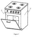
- FIG. 1 A representational view of the cooking apparatus which is the subject of the invention is provided in Figure 1 .
- FIG. 3c A representational view of the attachment of the connecting element of the cooking apparatus which is the subject of the invention to the lower grill and upper grill is provided in Figure 3c .
- FIG. 4c and 4d A representational view of the attachment of the connecting element of the cooking apparatus which is the subject of the invention to the lower grill and upper grill is provided in Figures 4c and 4d .
- FIG. 5d and 5e A representational view of the attachment of the connecting element of the cooking apparatus which is the subject of the invention to the lower grill and upper grill is provided in Figures 5d and 5e .
- FIG. 6c and 6d A representational view of the attachment of the connecting element of the cooking apparatus which is the subject of the invention to the lower grill and upper grill is provided in Figures 6c and 6d .
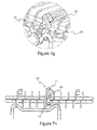
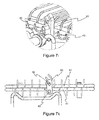
- FIG. 7g, 7h , 7i and 7k A representational view of the attachment of the connecting element of the cooking apparatus which is the subject of the invention to the lower grill and upper grill is provided in Figures 7g, 7h , 7i and 7k .
- the cooking apparatus which is the subject of the invention has an outer carcass (10) and a casing (20) enclosed in the said outer carcass (10).
- the said casing (20) defines a cooking chamber (21).
- the revolving grill (40) shown in Figures 2a and 2b and the grill stand (30) which positions the said revolving grill (40) in a manner which ensures that it can revolve at a specific height are positioned within the said cooking chamber (21).
- a supporting arm (31) which extends between the grill stand (30) and the revolving grill (40).
- the revolving grill (40) is attached to a bearing (32) provided on the supporting arm (31) by means of a bearing spindle (44) provided on at least one side.
- the revolving grill (40) comprises at least one lower grill (41) and at least one upper grill (42) in a manner which defines between them a compartment within which foodstuffs which are to be cooked may be placed.
- the said lower grill (41) and upper grill (42) are attached to each other by at least one connecting element (50).
- the lower grill (41) and the upper grill (42) are produced by bringing together multiple grill bars (43) of various sizes and forms in such a way as to create spaces between them.
- the said connecting element (50) is comprised of two arms (52) extending in a parallel fashion.
- the said arms (52) are formed in such a manner as to define at least two notches (51) between them.
- the arms (52) are structured symmetrically to create preferably circular notches (51).
- the connecting element (50) is preferably one-piece.
- the arms (52) are attached at one side but the other ends are free.
- an access opening (54) is provided in the connecting element (50) for access into the notches (51) of the grill bar (43) which is to be attached.
- the arms (52) each have a locking aperture (55) on the access opening (54) side.
- a locking pin (56) is fitted into the locking aperture (55) thereby ensuring that the connecting element (50) is fixed on the grill bars (43) in a manner which ensures that it will not come out.
- a threaded bolt can be used instead of the said locking pin (56).
- the lower grill (41) and the upper grill (42) can be distanced from one another by using different notches (51) on the connecting element (50), thereby preventing the foodstuffs from being crushed or the grill bars (43) being deformed.
- the arms are provided as two separate elements (52) attached to each other by a spring (53) between them.
- the said spring (53) is technically a twin armed spring which defines a torsion spring.
- the connecting element (50) has a shape like a clothes peg.
- the arms (52) are structured by means of bending a one-piece wire.
- the connecting part of the arms (52) are formed in a spiral fashion in order to produce a spring (53).
- the arms (52) have an S-like shape to define at least two notches (51) between them.
- the connecting element (50) In order to permit the connecting element (50) to be fitted to the lower grill (41) and the upper grill (42), it is fitted onto the grill bars (43) via the access opening (54) of the arms (52) shown in Figure 5b and then the connecting element (50) is turned in the direction in which the arms (52) stretch enabling the grill bars (43) to fit into the notches (51) as shown in Figures 5d and 5e .
- the one-piece connecting element (50) is formed in a manner by which it at least partially encircles the grill bars (43).
- the connecting element (50) is fitted by a square-shaped notch (51) at one end of it, over a grill bar (43) preferably in the lower grill (41) which corresponds to the form of the notch (51).
- the notches (51) in the connecting element (50) are fitted to the grill bars (43) of the upper grill (42).
- the notch (51) in the connecting element (50) forms a fixing by at least partly encircling the grill bar (43).
- the connecting element (50) has a notch (51) which forms an attachment to, preferably, the lower grill (41).
- the attachment of the connecting element (50) to the upper grill (42) is accomplished by means of notches (51) created by the arms (52) extending in different directions.
- the connecting element (50) fitted on one side to the lower grill (41) is also fixed to grill bars (43) of the upper grill (42) on the other side, thereby achieving a fixing.
- the lower grill (41) and the upper grill (42) are attached in a detachable fashion.
- the lower grill (41) and the upper grill (42) can be fitted in different positions enabling the positioning of foodstuffs of different thickness due to the notches (51) which are provided in multiple form.
- the connecting element (50) can additionally serve as a hinge.
Landscapes
- Engineering & Computer Science (AREA)
- Chemical & Material Sciences (AREA)
- Combustion & Propulsion (AREA)
- Mechanical Engineering (AREA)
- General Engineering & Computer Science (AREA)
- Food Science & Technology (AREA)
- Baking, Grill, Roasting (AREA)
Abstract
Description
- The invention relates to cooking apparatuses equipped with a revolving grill situated within a cooking chamber.
- In cooking apparatuses, foodstuffs placed on trays, grills and similar items are cooked by means of heating within a cooking chamber. In one of the cooking methods used, foodstuffs are revolved during the cooking using a revolving grill as described in application reference number
TR200910058 - The purpose of the invention is to introduce a revolving grill within a cooking chamber and a cooking apparatus equipped with a connecting element in order to lock together the upper and lower grills which form the said revolving grill.
- The purpose of the invention is to introduce a cooking apparatus with a connecting element in order to provide adjustability in the distance between the upper and lower grills of the invention.
- The invention is a cooking apparatus which includes a cooking chamber defined by a casing surrounded by an external carcass and a revolving grill comprising a lower grill and an upper grill each equipped with at least one grill bar, fitted with a bearing to permit it to revolve on its own access within the said cooking chamber. The revolving action can be achieved axially on a bearing spindle. Thus the said cooking apparatus includes at least one connecting element, attached by a shape fastening onto at least one grill bar on the lower and upper grill in order to connect the said lower grill and the upper grill to each other in a manner which permits them to be detachable. The connecting elements can be formed into at least two corresponding notches to provide a shape fastening. Thus the lower grill and upper grill will be prevented from separating from each other while the revolving grill turns.
- In a preferred embodiment of the invention, the said notch at least partially encircles the grill bar. Thus it ensures that when the grill bars are located in the notches, the lower grill and the upper grill are locked together.
- In a preferred embodiment of the invention, at least three notches are provided. Thus, when the amount of space between the lower grill and the upper grill is required to be increased, the positions of the grill bars can be changed.
- In a preferred embodiment of the invention, the said connecting element is constructed of a metal-based material. Thus, the connecting element is not affected by heat during cooking.
- In a preferred embodiment of the invention, the said connecting element includes at least two arms which define a notch between them. Also in another preferred embodiment of the invention, there is a spring which directs the said arms toward each other. This ensures that connecting elements on grill bars of different thickness hold the bars sufficiently firmly.
- A representational view of the cooking apparatus which is the subject of the invention is provided in
Figure 1 . - Representational views of the revolving grill of the cooking apparatus which is the subject of the invention is provided in
Figures 2a and 2b . - Representational views of the connecting element of the cooking apparatus which is the subject of the invention are provided in
Figures 3a and 3b . - A representational view of the attachment of the connecting element of the cooking apparatus which is the subject of the invention to the lower grill and upper grill is provided in
Figure 3c . - Representational views of an alternative connecting element of the cooking apparatus which is the subject of the invention are provided in
Figures 4a and 4b . - A representational view of the attachment of the connecting element of the cooking apparatus which is the subject of the invention to the lower grill and upper grill is provided in
Figures 4c and 4d . - Representational views of another alternative connecting element of the cooking apparatus which is the subject of the invention are provided in
Figures 5a, 5b and 5c . - A representational view of the attachment of the connecting element of the cooking apparatus which is the subject of the invention to the lower grill and upper grill is provided in
Figures 5d and 5e . - Representational views of another alternative connecting element of the cooking apparatus which is the subject of the invention are provided in
Figures 6a and 6b . - A representational view of the attachment of the connecting element of the cooking apparatus which is the subject of the invention to the lower grill and upper grill is provided in
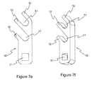
Figures 6c and 6d . - Representational views of another alternative connecting element of the cooking apparatus which is the subject of the invention are provided in
Figures 7a, 7b, 7c, 7d ,7e and 7f . - A representational view of the attachment of the connecting element of the cooking apparatus which is the subject of the invention to the lower grill and upper grill is provided in
Figures 7g, 7h ,7i and 7k . - This detailed explanation of the revolving grill which is the subject of the invention is given only in order to explain the subject more clearly, and shall in no way be restrictive in its effect.
- With reference to
Figure 1 : the cooking apparatus which is the subject of the invention has an outer carcass (10) and a casing (20) enclosed in the said outer carcass (10). The said casing (20) defines a cooking chamber (21). The revolving grill (40) shown inFigures 2a and 2b and the grill stand (30) which positions the said revolving grill (40) in a manner which ensures that it can revolve at a specific height are positioned within the said cooking chamber (21). In order to provide an attachment between the grill stand (30) and the revolving grill (40) there is a supporting arm (31) which extends between the grill stand (30) and the revolving grill (40). The revolving grill (40) is attached to a bearing (32) provided on the supporting arm (31) by means of a bearing spindle (44) provided on at least one side. The revolving grill (40) comprises at least one lower grill (41) and at least one upper grill (42) in a manner which defines between them a compartment within which foodstuffs which are to be cooked may be placed. The said lower grill (41) and upper grill (42) are attached to each other by at least one connecting element (50). Thus while the revolving grill (40) is revolving, separation of the lower grill (41) and the upper grill (42) is prevented, ensuring that the foodstuff being cooked is not spilled or dropped. The lower grill (41) and the upper grill (42) are produced by bringing together multiple grill bars (43) of various sizes and forms in such a way as to create spaces between them. - In the embodiment of the invention shown in
Figures 3a and 3b , the said connecting element (50) is comprised of two arms (52) extending in a parallel fashion. The said arms (52) are formed in such a manner as to define at least two notches (51) between them. The arms (52) are structured symmetrically to create preferably circular notches (51). The connecting element (50) is preferably one-piece. The arms (52) are attached at one side but the other ends are free. Thus an access opening (54) is provided in the connecting element (50) for access into the notches (51) of the grill bar (43) which is to be attached. The arms (52) each have a locking aperture (55) on the access opening (54) side. As may be seen inFigure 3c , after the grill bars (43) of the lower grill (41) and the upper grill (42) have been located in the notches (51) in the connecting element (50), a locking pin (56) is fitted into the locking aperture (55) thereby ensuring that the connecting element (50) is fixed on the grill bars (43) in a manner which ensures that it will not come out. A threaded bolt can be used instead of the said locking pin (56). In a preferred embodiment of the invention there are more than two notches (51) created between the arms (52) by which the lower grill (41) and the upper grill (42) can be fixed to create a distance between them. Thus, when the food which is to be cooked does not fit between the lower grill (41) and the upper grill (42), the lower grill (41) and the upper grill (42) can be distanced from one another by using different notches (51) on the connecting element (50), thereby preventing the foodstuffs from being crushed or the grill bars (43) being deformed. - In an alternative embodiment of the connecting element (50) shown in
Figures 4a and 4b , the arms are provided as two separate elements (52) attached to each other by a spring (53) between them. The said spring (53) is technically a twin armed spring which defines a torsion spring. Thus, the connecting element (50) has a shape like a clothes peg. As may be seen inFigures 4c and 4d , when the connecting element (50) is fitted onto the grill bars (43) of the lower grill (41) and the upper grill (42) it is fixed by means of force applied by the spring (53). Thus there is no requirement for an additional element to effect locking, and assembly can be conveniently achieved. - In an alternative embodiment of the connecting element (50) shown in
Figures 5a, 5b and 5c , the arms (52) are structured by means of bending a one-piece wire. In the course of the said forming process the connecting part of the arms (52) are formed in a spiral fashion in order to produce a spring (53). The arms (52) have an S-like shape to define at least two notches (51) between them. In order to permit the connecting element (50) to be fitted to the lower grill (41) and the upper grill (42), it is fitted onto the grill bars (43) via the access opening (54) of the arms (52) shown inFigure 5b and then the connecting element (50) is turned in the direction in which the arms (52) stretch enabling the grill bars (43) to fit into the notches (51) as shown inFigures 5d and 5e . - In an alternative embodiment shown in
Figures 6a and 6b , the one-piece connecting element (50) is formed in a manner by which it at least partially encircles the grill bars (43). In a preferred embodiment, the connecting element (50) is fitted by a square-shaped notch (51) at one end of it, over a grill bar (43) preferably in the lower grill (41) which corresponds to the form of the notch (51). As may be seen inFigures 6c and 6d , the notches (51) in the connecting element (50) are fitted to the grill bars (43) of the upper grill (42). The notch (51) in the connecting element (50) forms a fixing by at least partly encircling the grill bar (43). - As may be seen in
Figures 7a to 7f , the connecting element (50) has a notch (51) which forms an attachment to, preferably, the lower grill (41). The attachment of the connecting element (50) to the upper grill (42) is accomplished by means of notches (51) created by the arms (52) extending in different directions. Thus the connecting element (50) fitted on one side to the lower grill (41) is also fixed to grill bars (43) of the upper grill (42) on the other side, thereby achieving a fixing. - In all of the said embodiments the lower grill (41) and the upper grill (42) are attached in a detachable fashion. The lower grill (41) and the upper grill (42) can be fitted in different positions enabling the positioning of foodstuffs of different thickness due to the notches (51) which are provided in multiple form. Also in the said embodiments, the connecting element (50) can additionally serve as a hinge.
-
- 10
- External carcass
- 20
- Casing
- 21
- Cooking chamber
- 30
- Grill stand
- 31
- Supporting arm
- 32
- Bearing
- 40
- Revolving Grill
- 41
- Lower grill
- 42
- Upper grill
- 43
- Grill bar
- 44
- Bearing spindle
- 50
- Connecting element
- 51
- Notch
- 52
- Arm
- 53
- Spring
- 54
- Access opening
- 55
- Locking aperture
- 56
- Locking pin
Claims (6)
- A cooking apparatus which comprises an external carcass (10) enclosing a casing (20) to define a cooking chamber (21) and within the said cooking chamber (21) a revolving grill (40) comprising a lower grill (41) and an upper grill (42) each with at least one grill bar, fitted with a bearing and capable of revolving on its own axis, characterized in that in order to permit the lower grill (41) and the upper grill (42) to be connected in a detachable fashion, it contains a connecting element (50) which is adapted to fit at least one grill bar each (43) located on the lower grill (41) and the upper grill (42).
- The cooking apparatus as claimed in claim 1, the connecting element (50) including at least one notch (51) which at least partly encircles the grill bar (43).
- The cooking apparatus as claimed in claim 2, the notches (51) being at least three in number.
- The cooking apparatus as claimed in any one of the previous claims, the said connecting element (50) being manufactured of a metal-based material.
- The cooking apparatus as claimed in claim 2, in which the connecting element (50) includes at least two arms (52) which define a notch (51) between them.
- The cooking apparatus as claimed in claim 5, including at least one spring (53) which directs the said arms (52) toward one another.
Applications Claiming Priority (1)
| Application Number | Priority Date | Filing Date | Title |
|---|---|---|---|
| TR201311770 | 2013-10-07 |
Publications (2)
| Publication Number | Publication Date |
|---|---|
| EP2857757A1 true EP2857757A1 (en) | 2015-04-08 |
| EP2857757B1 EP2857757B1 (en) | 2017-03-01 |
Family
ID=51786772
Family Applications (1)
| Application Number | Title | Priority Date | Filing Date |
|---|---|---|---|
| EP14187039.4A Not-in-force EP2857757B1 (en) | 2013-10-07 | 2014-09-30 | A cooking apparatus with a revolving grill |
Country Status (1)
| Country | Link |
|---|---|
| EP (1) | EP2857757B1 (en) |
Cited By (3)
| Publication number | Priority date | Publication date | Assignee | Title |
|---|---|---|---|---|
| USD992352S1 (en) | 2021-08-05 | 2023-07-18 | Weber-Stephen Products Llc | Rotisserie skewer rack |
| US12433446B2 (en) | 2021-08-04 | 2025-10-07 | Weber-Stephen Products Llc | Transversely-loadable rotisserie skewer racks for grills |
| US12543889B2 (en) | 2021-08-04 | 2026-02-10 | Weber-Stephen Products Llc | Transversely-loadable rotisserie baskets for grills |
Citations (9)
| Publication number | Priority date | Publication date | Assignee | Title |
|---|---|---|---|---|
| US4452131A (en) * | 1981-08-26 | 1984-06-05 | Thomas Gaskins | Universal clip and grill assembly |
| US5410948A (en) * | 1994-03-21 | 1995-05-02 | Eickmeyer; Bryon G. | Cooking grills with automatically rotatable food supporting racks |
| US6418835B1 (en) * | 2002-01-30 | 2002-07-16 | Ching-Mei Lin | Rotisserie oven structure |
| US20050172835A1 (en) * | 2004-02-05 | 2005-08-11 | Lamaster Alan L. | Vertically oriented jerky dehydrator |
| WO2007031035A1 (en) * | 2005-09-14 | 2007-03-22 | Andreas Angelides | Mechanised rotating grill system for grilling foodstuffs |
| US20070240698A1 (en) * | 2006-04-17 | 2007-10-18 | Holbrook Paul R | Flip-over accessory for barbecue grill |
| CN102028416A (en) * | 2010-11-23 | 2011-04-27 | 合肥荣事达三洋电器股份有限公司 | Rotatable roasting supporter |
| TR200910058A2 (en) | 2009-12-31 | 2011-07-21 | Bsh Ev Aletleri̇ San. Ve Ti̇c. A.Ş. | An oven with a rotatable grill in the cooking chamber |
| CN202303513U (en) * | 2011-10-19 | 2012-07-04 | 合肥荣事达三洋电器股份有限公司 | Microwave oven provided with automatic turnover grill |
-
2014
- 2014-09-30 EP EP14187039.4A patent/EP2857757B1/en not_active Not-in-force
Patent Citations (9)
| Publication number | Priority date | Publication date | Assignee | Title |
|---|---|---|---|---|
| US4452131A (en) * | 1981-08-26 | 1984-06-05 | Thomas Gaskins | Universal clip and grill assembly |
| US5410948A (en) * | 1994-03-21 | 1995-05-02 | Eickmeyer; Bryon G. | Cooking grills with automatically rotatable food supporting racks |
| US6418835B1 (en) * | 2002-01-30 | 2002-07-16 | Ching-Mei Lin | Rotisserie oven structure |
| US20050172835A1 (en) * | 2004-02-05 | 2005-08-11 | Lamaster Alan L. | Vertically oriented jerky dehydrator |
| WO2007031035A1 (en) * | 2005-09-14 | 2007-03-22 | Andreas Angelides | Mechanised rotating grill system for grilling foodstuffs |
| US20070240698A1 (en) * | 2006-04-17 | 2007-10-18 | Holbrook Paul R | Flip-over accessory for barbecue grill |
| TR200910058A2 (en) | 2009-12-31 | 2011-07-21 | Bsh Ev Aletleri̇ San. Ve Ti̇c. A.Ş. | An oven with a rotatable grill in the cooking chamber |
| CN102028416A (en) * | 2010-11-23 | 2011-04-27 | 合肥荣事达三洋电器股份有限公司 | Rotatable roasting supporter |
| CN202303513U (en) * | 2011-10-19 | 2012-07-04 | 合肥荣事达三洋电器股份有限公司 | Microwave oven provided with automatic turnover grill |
Cited By (3)
| Publication number | Priority date | Publication date | Assignee | Title |
|---|---|---|---|---|
| US12433446B2 (en) | 2021-08-04 | 2025-10-07 | Weber-Stephen Products Llc | Transversely-loadable rotisserie skewer racks for grills |
| US12543889B2 (en) | 2021-08-04 | 2026-02-10 | Weber-Stephen Products Llc | Transversely-loadable rotisserie baskets for grills |
| USD992352S1 (en) | 2021-08-05 | 2023-07-18 | Weber-Stephen Products Llc | Rotisserie skewer rack |
Also Published As
| Publication number | Publication date |
|---|---|
| EP2857757B1 (en) | 2017-03-01 |
Similar Documents
| Publication | Publication Date | Title |
|---|---|---|
| US20110097468A1 (en) | Rotisserie chili roaster | |
| EP2857757B1 (en) | A cooking apparatus with a revolving grill | |
| US20140345593A1 (en) | Through-type barbecue driving device allowing arbitrary adjustment of installation position of rotating rod | |
| US20100230404A1 (en) | Rack Assembly | |
| US20180317703A1 (en) | Barbecue spit with grill nets | |
| US2040648A (en) | Egg holder | |
| KR200469270Y1 (en) | Cooking Tagine Pot | |
| US20010037584A1 (en) | Coffee roaster attachments for home rotisserie oven appliance | |
| US9155423B2 (en) | Roasting rack | |
| US2183938A (en) | Marshmallow toaster | |
| US20160338536A1 (en) | Barbecue grill comprising a height-adjustable cooking grill | |
| WO2008081213B1 (en) | Automated machine for fried dough foods fried in pans | |
| US20150020697A1 (en) | Barbecue Support Assembly | |
| EP0974031B1 (en) | Spitting device for use in a microwave oven | |
| KR100863801B1 (en) | Rotary roasting device for table mounting and table in which the device is configured | |
| KR101214728B1 (en) | multi function oven | |
| DE202018102671U1 (en) | roasting machine | |
| US6327967B1 (en) | Assembled multi-functional meat roast frame | |
| US11229319B2 (en) | Grill device and coupling and corresponding plate for food to be grilled | |
| WO2016072824A1 (en) | A fold able device for preparing food on an open fire | |
| KR200444331Y1 (en) | BBQ Grilled | |
| EP3027090B1 (en) | Hot beverage preparation machine | |
| US102348A (en) | Henderson willard | |
| US20130216675A1 (en) | Pliable support for a food product or preparation in a roasting pan | |
| KR101566455B1 (en) | Cooking Assistant Equipment for Frying |
Legal Events
| Date | Code | Title | Description |
|---|---|---|---|
| PUAI | Public reference made under article 153(3) epc to a published international application that has entered the european phase |
Free format text: ORIGINAL CODE: 0009012 |
|
| 17P | Request for examination filed |
Effective date: 20140930 |
|
| AK | Designated contracting states |
Kind code of ref document: A1 Designated state(s): AL AT BE BG CH CY CZ DE DK EE ES FI FR GB GR HR HU IE IS IT LI LT LU LV MC MK MT NL NO PL PT RO RS SE SI SK SM TR |
|
| AX | Request for extension of the european patent |
Extension state: BA ME |
|
| R17P | Request for examination filed (corrected) |
Effective date: 20151008 |
|
| RBV | Designated contracting states (corrected) |
Designated state(s): AL AT BE BG CH CY CZ DE DK EE ES FI FR GB GR HR HU IE IS IT LI LT LU LV MC MK MT NL NO PL PT RO RS SE SI SK SM TR |
|
| GRAJ | Information related to disapproval of communication of intention to grant by the applicant or resumption of examination proceedings by the epo deleted |
Free format text: ORIGINAL CODE: EPIDOSDIGR1 |
|
| GRAP | Despatch of communication of intention to grant a patent |
Free format text: ORIGINAL CODE: EPIDOSNIGR1 |
|
| INTG | Intention to grant announced |
Effective date: 20161006 |
|
| GRAS | Grant fee paid |
Free format text: ORIGINAL CODE: EPIDOSNIGR3 |
|
| GRAA | (expected) grant |
Free format text: ORIGINAL CODE: 0009210 |
|
| AK | Designated contracting states |
Kind code of ref document: B1 Designated state(s): AL AT BE BG CH CY CZ DE DK EE ES FI FR GB GR HR HU IE IS IT LI LT LU LV MC MK MT NL NO PL PT RO RS SE SI SK SM TR |
|
| REG | Reference to a national code |
Ref country code: GB Ref legal event code: FG4D |
|
| REG | Reference to a national code |
Ref country code: CH Ref legal event code: EP Ref country code: AT Ref legal event code: REF Ref document number: 871835 Country of ref document: AT Kind code of ref document: T Effective date: 20170315 |
|
| REG | Reference to a national code |
Ref country code: IE Ref legal event code: FG4D |
|
| REG | Reference to a national code |
Ref country code: DE Ref legal event code: R096 Ref document number: 602014007069 Country of ref document: DE |
|
| REG | Reference to a national code |
Ref country code: NL Ref legal event code: MP Effective date: 20170301 |
|
| REG | Reference to a national code |
Ref country code: LT Ref legal event code: MG4D |
|
| REG | Reference to a national code |
Ref country code: AT Ref legal event code: MK05 Ref document number: 871835 Country of ref document: AT Kind code of ref document: T Effective date: 20170301 |
|
| PG25 | Lapsed in a contracting state [announced via postgrant information from national office to epo] |
Ref country code: NO Free format text: LAPSE BECAUSE OF FAILURE TO SUBMIT A TRANSLATION OF THE DESCRIPTION OR TO PAY THE FEE WITHIN THE PRESCRIBED TIME-LIMIT Effective date: 20170601 Ref country code: HR Free format text: LAPSE BECAUSE OF FAILURE TO SUBMIT A TRANSLATION OF THE DESCRIPTION OR TO PAY THE FEE WITHIN THE PRESCRIBED TIME-LIMIT Effective date: 20170301 Ref country code: GR Free format text: LAPSE BECAUSE OF FAILURE TO SUBMIT A TRANSLATION OF THE DESCRIPTION OR TO PAY THE FEE WITHIN THE PRESCRIBED TIME-LIMIT Effective date: 20170602 Ref country code: LT Free format text: LAPSE BECAUSE OF FAILURE TO SUBMIT A TRANSLATION OF THE DESCRIPTION OR TO PAY THE FEE WITHIN THE PRESCRIBED TIME-LIMIT Effective date: 20170301 Ref country code: FI Free format text: LAPSE BECAUSE OF FAILURE TO SUBMIT A TRANSLATION OF THE DESCRIPTION OR TO PAY THE FEE WITHIN THE PRESCRIBED TIME-LIMIT Effective date: 20170301 |
|
| PG25 | Lapsed in a contracting state [announced via postgrant information from national office to epo] |
Ref country code: LV Free format text: LAPSE BECAUSE OF FAILURE TO SUBMIT A TRANSLATION OF THE DESCRIPTION OR TO PAY THE FEE WITHIN THE PRESCRIBED TIME-LIMIT Effective date: 20170301 Ref country code: BG Free format text: LAPSE BECAUSE OF FAILURE TO SUBMIT A TRANSLATION OF THE DESCRIPTION OR TO PAY THE FEE WITHIN THE PRESCRIBED TIME-LIMIT Effective date: 20170601 Ref country code: RS Free format text: LAPSE BECAUSE OF FAILURE TO SUBMIT A TRANSLATION OF THE DESCRIPTION OR TO PAY THE FEE WITHIN THE PRESCRIBED TIME-LIMIT Effective date: 20170301 Ref country code: AT Free format text: LAPSE BECAUSE OF FAILURE TO SUBMIT A TRANSLATION OF THE DESCRIPTION OR TO PAY THE FEE WITHIN THE PRESCRIBED TIME-LIMIT Effective date: 20170301 Ref country code: ES Free format text: LAPSE BECAUSE OF FAILURE TO SUBMIT A TRANSLATION OF THE DESCRIPTION OR TO PAY THE FEE WITHIN THE PRESCRIBED TIME-LIMIT Effective date: 20170301 Ref country code: SE Free format text: LAPSE BECAUSE OF FAILURE TO SUBMIT A TRANSLATION OF THE DESCRIPTION OR TO PAY THE FEE WITHIN THE PRESCRIBED TIME-LIMIT Effective date: 20170301 |
|
| PG25 | Lapsed in a contracting state [announced via postgrant information from national office to epo] |
Ref country code: NL Free format text: LAPSE BECAUSE OF FAILURE TO SUBMIT A TRANSLATION OF THE DESCRIPTION OR TO PAY THE FEE WITHIN THE PRESCRIBED TIME-LIMIT Effective date: 20170301 |
|
| PG25 | Lapsed in a contracting state [announced via postgrant information from national office to epo] |
Ref country code: RO Free format text: LAPSE BECAUSE OF FAILURE TO SUBMIT A TRANSLATION OF THE DESCRIPTION OR TO PAY THE FEE WITHIN THE PRESCRIBED TIME-LIMIT Effective date: 20170301 Ref country code: CZ Free format text: LAPSE BECAUSE OF FAILURE TO SUBMIT A TRANSLATION OF THE DESCRIPTION OR TO PAY THE FEE WITHIN THE PRESCRIBED TIME-LIMIT Effective date: 20170301 Ref country code: EE Free format text: LAPSE BECAUSE OF FAILURE TO SUBMIT A TRANSLATION OF THE DESCRIPTION OR TO PAY THE FEE WITHIN THE PRESCRIBED TIME-LIMIT Effective date: 20170301 Ref country code: IT Free format text: LAPSE BECAUSE OF FAILURE TO SUBMIT A TRANSLATION OF THE DESCRIPTION OR TO PAY THE FEE WITHIN THE PRESCRIBED TIME-LIMIT Effective date: 20170301 Ref country code: SK Free format text: LAPSE BECAUSE OF FAILURE TO SUBMIT A TRANSLATION OF THE DESCRIPTION OR TO PAY THE FEE WITHIN THE PRESCRIBED TIME-LIMIT Effective date: 20170301 |
|
| PG25 | Lapsed in a contracting state [announced via postgrant information from national office to epo] |
Ref country code: SM Free format text: LAPSE BECAUSE OF FAILURE TO SUBMIT A TRANSLATION OF THE DESCRIPTION OR TO PAY THE FEE WITHIN THE PRESCRIBED TIME-LIMIT Effective date: 20170301 Ref country code: IS Free format text: LAPSE BECAUSE OF FAILURE TO SUBMIT A TRANSLATION OF THE DESCRIPTION OR TO PAY THE FEE WITHIN THE PRESCRIBED TIME-LIMIT Effective date: 20170701 Ref country code: PL Free format text: LAPSE BECAUSE OF FAILURE TO SUBMIT A TRANSLATION OF THE DESCRIPTION OR TO PAY THE FEE WITHIN THE PRESCRIBED TIME-LIMIT Effective date: 20170301 Ref country code: PT Free format text: LAPSE BECAUSE OF FAILURE TO SUBMIT A TRANSLATION OF THE DESCRIPTION OR TO PAY THE FEE WITHIN THE PRESCRIBED TIME-LIMIT Effective date: 20170703 |
|
| PGFP | Annual fee paid to national office [announced via postgrant information from national office to epo] |
Ref country code: TR Payment date: 20170920 Year of fee payment: 4 |
|
| REG | Reference to a national code |
Ref country code: DE Ref legal event code: R097 Ref document number: 602014007069 Country of ref document: DE |
|
| PLBE | No opposition filed within time limit |
Free format text: ORIGINAL CODE: 0009261 |
|
| STAA | Information on the status of an ep patent application or granted ep patent |
Free format text: STATUS: NO OPPOSITION FILED WITHIN TIME LIMIT |
|
| PG25 | Lapsed in a contracting state [announced via postgrant information from national office to epo] |
Ref country code: DK Free format text: LAPSE BECAUSE OF FAILURE TO SUBMIT A TRANSLATION OF THE DESCRIPTION OR TO PAY THE FEE WITHIN THE PRESCRIBED TIME-LIMIT Effective date: 20170301 |
|
| 26N | No opposition filed |
Effective date: 20171204 |
|
| PG25 | Lapsed in a contracting state [announced via postgrant information from national office to epo] |
Ref country code: SI Free format text: LAPSE BECAUSE OF FAILURE TO SUBMIT A TRANSLATION OF THE DESCRIPTION OR TO PAY THE FEE WITHIN THE PRESCRIBED TIME-LIMIT Effective date: 20170301 |
|
| REG | Reference to a national code |
Ref country code: DE Ref legal event code: R119 Ref document number: 602014007069 Country of ref document: DE |
|
| REG | Reference to a national code |
Ref country code: CH Ref legal event code: PL |
|
| PG25 | Lapsed in a contracting state [announced via postgrant information from national office to epo] |
Ref country code: MC Free format text: LAPSE BECAUSE OF FAILURE TO SUBMIT A TRANSLATION OF THE DESCRIPTION OR TO PAY THE FEE WITHIN THE PRESCRIBED TIME-LIMIT Effective date: 20170301 |
|
| REG | Reference to a national code |
Ref country code: IE Ref legal event code: MM4A |
|
| REG | Reference to a national code |
Ref country code: BE Ref legal event code: MM Effective date: 20170930 |
|
| PG25 | Lapsed in a contracting state [announced via postgrant information from national office to epo] |
Ref country code: LU Free format text: LAPSE BECAUSE OF NON-PAYMENT OF DUE FEES Effective date: 20170930 |
|
| REG | Reference to a national code |
Ref country code: FR Ref legal event code: ST Effective date: 20180531 |
|
| PG25 | Lapsed in a contracting state [announced via postgrant information from national office to epo] |
Ref country code: IE Free format text: LAPSE BECAUSE OF NON-PAYMENT OF DUE FEES Effective date: 20170930 Ref country code: DE Free format text: LAPSE BECAUSE OF NON-PAYMENT OF DUE FEES Effective date: 20180404 Ref country code: LI Free format text: LAPSE BECAUSE OF NON-PAYMENT OF DUE FEES Effective date: 20170930 Ref country code: CH Free format text: LAPSE BECAUSE OF NON-PAYMENT OF DUE FEES Effective date: 20170930 |
|
| PG25 | Lapsed in a contracting state [announced via postgrant information from national office to epo] |
Ref country code: FR Free format text: LAPSE BECAUSE OF NON-PAYMENT OF DUE FEES Effective date: 20171002 Ref country code: BE Free format text: LAPSE BECAUSE OF NON-PAYMENT OF DUE FEES Effective date: 20170930 |
|
| PG25 | Lapsed in a contracting state [announced via postgrant information from national office to epo] |
Ref country code: MT Free format text: LAPSE BECAUSE OF NON-PAYMENT OF DUE FEES Effective date: 20170930 |
|
| GBPC | Gb: european patent ceased through non-payment of renewal fee |
Effective date: 20180930 |
|
| PG25 | Lapsed in a contracting state [announced via postgrant information from national office to epo] |
Ref country code: HU Free format text: LAPSE BECAUSE OF FAILURE TO SUBMIT A TRANSLATION OF THE DESCRIPTION OR TO PAY THE FEE WITHIN THE PRESCRIBED TIME-LIMIT; INVALID AB INITIO Effective date: 20140930 |
|
| PG25 | Lapsed in a contracting state [announced via postgrant information from national office to epo] |
Ref country code: CY Free format text: LAPSE BECAUSE OF FAILURE TO SUBMIT A TRANSLATION OF THE DESCRIPTION OR TO PAY THE FEE WITHIN THE PRESCRIBED TIME-LIMIT Effective date: 20170301 Ref country code: GB Free format text: LAPSE BECAUSE OF NON-PAYMENT OF DUE FEES Effective date: 20180930 |
|
| PG25 | Lapsed in a contracting state [announced via postgrant information from national office to epo] |
Ref country code: MK Free format text: LAPSE BECAUSE OF FAILURE TO SUBMIT A TRANSLATION OF THE DESCRIPTION OR TO PAY THE FEE WITHIN THE PRESCRIBED TIME-LIMIT Effective date: 20170301 |
|
| PG25 | Lapsed in a contracting state [announced via postgrant information from national office to epo] |
Ref country code: AL Free format text: LAPSE BECAUSE OF FAILURE TO SUBMIT A TRANSLATION OF THE DESCRIPTION OR TO PAY THE FEE WITHIN THE PRESCRIBED TIME-LIMIT Effective date: 20170301 |
|
| PG25 | Lapsed in a contracting state [announced via postgrant information from national office to epo] |
Ref country code: TR Free format text: LAPSE BECAUSE OF NON-PAYMENT OF DUE FEES Effective date: 20190930 |