EP2857680A2 - Hand-operated piston pump - Google Patents
Hand-operated piston pump Download PDFInfo
- Publication number
- EP2857680A2 EP2857680A2 EP14184661.8A EP14184661A EP2857680A2 EP 2857680 A2 EP2857680 A2 EP 2857680A2 EP 14184661 A EP14184661 A EP 14184661A EP 2857680 A2 EP2857680 A2 EP 2857680A2
- Authority
- EP
- European Patent Office
- Prior art keywords
- drive shaft
- rotor
- valve plate
- upper flange
- conduits
- Prior art date
- Legal status (The legal status is an assumption and is not a legal conclusion. Google has not performed a legal analysis and makes no representation as to the accuracy of the status listed.)
- Granted
Links
- 239000012530 fluid Substances 0.000 claims abstract description 60
- 230000006835 compression Effects 0.000 claims abstract description 22
- 238000007906 compression Methods 0.000 claims abstract description 22
- 238000007599 discharging Methods 0.000 claims description 5
- 238000010276 construction Methods 0.000 description 9
- 238000007789 sealing Methods 0.000 description 7
- 238000007667 floating Methods 0.000 description 6
- 238000004519 manufacturing process Methods 0.000 description 5
- 230000000694 effects Effects 0.000 description 4
- 238000010926 purge Methods 0.000 description 3
- 241000380131 Ammophila arenaria Species 0.000 description 2
- 238000013022 venting Methods 0.000 description 2
- 238000004891 communication Methods 0.000 description 1
- 238000013016 damping Methods 0.000 description 1
- 238000006073 displacement reaction Methods 0.000 description 1
- 238000005553 drilling Methods 0.000 description 1
- 238000012423 maintenance Methods 0.000 description 1
- 239000000463 material Substances 0.000 description 1
- 238000005192 partition Methods 0.000 description 1
- 230000036316 preload Effects 0.000 description 1
- 230000001737 promoting effect Effects 0.000 description 1
- 238000011084 recovery Methods 0.000 description 1
- 230000000630 rising effect Effects 0.000 description 1
- 238000004381 surface treatment Methods 0.000 description 1
Images

Classifications
-
- B—PERFORMING OPERATIONS; TRANSPORTING
- B63—SHIPS OR OTHER WATERBORNE VESSELS; RELATED EQUIPMENT
- B63H—MARINE PROPULSION OR STEERING
- B63H25/00—Steering; Slowing-down otherwise than by use of propulsive elements; Dynamic anchoring, i.e. positioning vessels by means of main or auxiliary propulsive elements
- B63H25/06—Steering by rudders
- B63H25/08—Steering gear
- B63H25/14—Steering gear power assisted; power driven, i.e. using steering engine
- B63H25/26—Steering engines
- B63H25/28—Steering engines of fluid type
- B63H25/30—Steering engines of fluid type hydraulic
-
- F—MECHANICAL ENGINEERING; LIGHTING; HEATING; WEAPONS; BLASTING
- F04—POSITIVE - DISPLACEMENT MACHINES FOR LIQUIDS; PUMPS FOR LIQUIDS OR ELASTIC FLUIDS
- F04B—POSITIVE-DISPLACEMENT MACHINES FOR LIQUIDS; PUMPS
- F04B1/00—Multi-cylinder machines or pumps characterised by number or arrangement of cylinders
- F04B1/12—Multi-cylinder machines or pumps characterised by number or arrangement of cylinders having cylinder axes coaxial with, or parallel or inclined to, main shaft axis
- F04B1/20—Multi-cylinder machines or pumps characterised by number or arrangement of cylinders having cylinder axes coaxial with, or parallel or inclined to, main shaft axis having rotary cylinder block
-
- B—PERFORMING OPERATIONS; TRANSPORTING
- B63—SHIPS OR OTHER WATERBORNE VESSELS; RELATED EQUIPMENT
- B63H—MARINE PROPULSION OR STEERING
- B63H25/00—Steering; Slowing-down otherwise than by use of propulsive elements; Dynamic anchoring, i.e. positioning vessels by means of main or auxiliary propulsive elements
- B63H25/06—Steering by rudders
- B63H25/08—Steering gear
- B63H25/14—Steering gear power assisted; power driven, i.e. using steering engine
- B63H25/18—Transmitting of movement of initiating means to steering engine
- B63H25/22—Transmitting of movement of initiating means to steering engine by fluid means
-
- F—MECHANICAL ENGINEERING; LIGHTING; HEATING; WEAPONS; BLASTING
- F01—MACHINES OR ENGINES IN GENERAL; ENGINE PLANTS IN GENERAL; STEAM ENGINES
- F01B—MACHINES OR ENGINES, IN GENERAL OR OF POSITIVE-DISPLACEMENT TYPE, e.g. STEAM ENGINES
- F01B3/00—Reciprocating-piston machines or engines with cylinder axes coaxial with, or parallel or inclined to, main shaft axis
- F01B3/0032—Reciprocating-piston machines or engines with cylinder axes coaxial with, or parallel or inclined to, main shaft axis having rotary cylinder block
-
- F—MECHANICAL ENGINEERING; LIGHTING; HEATING; WEAPONS; BLASTING
- F04—POSITIVE - DISPLACEMENT MACHINES FOR LIQUIDS; PUMPS FOR LIQUIDS OR ELASTIC FLUIDS
- F04B—POSITIVE-DISPLACEMENT MACHINES FOR LIQUIDS; PUMPS
- F04B1/00—Multi-cylinder machines or pumps characterised by number or arrangement of cylinders
- F04B1/12—Multi-cylinder machines or pumps characterised by number or arrangement of cylinders having cylinder axes coaxial with, or parallel or inclined to, main shaft axis
- F04B1/20—Multi-cylinder machines or pumps characterised by number or arrangement of cylinders having cylinder axes coaxial with, or parallel or inclined to, main shaft axis having rotary cylinder block
- F04B1/2007—Arrangements for pressing the cylinder barrel against the valve plate, e.g. by fluid pressure
-
- F—MECHANICAL ENGINEERING; LIGHTING; HEATING; WEAPONS; BLASTING
- F04—POSITIVE - DISPLACEMENT MACHINES FOR LIQUIDS; PUMPS FOR LIQUIDS OR ELASTIC FLUIDS
- F04B—POSITIVE-DISPLACEMENT MACHINES FOR LIQUIDS; PUMPS
- F04B1/00—Multi-cylinder machines or pumps characterised by number or arrangement of cylinders
- F04B1/12—Multi-cylinder machines or pumps characterised by number or arrangement of cylinders having cylinder axes coaxial with, or parallel or inclined to, main shaft axis
- F04B1/20—Multi-cylinder machines or pumps characterised by number or arrangement of cylinders having cylinder axes coaxial with, or parallel or inclined to, main shaft axis having rotary cylinder block
- F04B1/2014—Details or component parts
- F04B1/2042—Valves
-
- F—MECHANICAL ENGINEERING; LIGHTING; HEATING; WEAPONS; BLASTING
- F04—POSITIVE - DISPLACEMENT MACHINES FOR LIQUIDS; PUMPS FOR LIQUIDS OR ELASTIC FLUIDS
- F04B—POSITIVE-DISPLACEMENT MACHINES FOR LIQUIDS; PUMPS
- F04B1/00—Multi-cylinder machines or pumps characterised by number or arrangement of cylinders
- F04B1/12—Multi-cylinder machines or pumps characterised by number or arrangement of cylinders having cylinder axes coaxial with, or parallel or inclined to, main shaft axis
- F04B1/20—Multi-cylinder machines or pumps characterised by number or arrangement of cylinders having cylinder axes coaxial with, or parallel or inclined to, main shaft axis having rotary cylinder block
- F04B1/22—Multi-cylinder machines or pumps characterised by number or arrangement of cylinders having cylinder axes coaxial with, or parallel or inclined to, main shaft axis having rotary cylinder block having two or more sets of cylinders or pistons
-
- F—MECHANICAL ENGINEERING; LIGHTING; HEATING; WEAPONS; BLASTING
- F04—POSITIVE - DISPLACEMENT MACHINES FOR LIQUIDS; PUMPS FOR LIQUIDS OR ELASTIC FLUIDS
- F04B—POSITIVE-DISPLACEMENT MACHINES FOR LIQUIDS; PUMPS
- F04B9/00—Piston machines or pumps characterised by the driving or driven means to or from their working members
- F04B9/14—Pumps characterised by muscle-power operation
Definitions
- the present invention relates to a hand-operated piston pump, particularly for directional control of watercraft, boats or the like.
- the pump comprises a drive shaft, which is rotatably mounted in a housing case, a rotor, which is mounted in the housing case and is rotationally integral with the drive shaft, said rotor having a plurality of axial compression chambers formed in the body of the rotor.
- the axial compression chambers surround the drive shaft, a piston being axially slidably housed in each compression chamber and biased by elastic means, with one end projecting out of one end side of the corresponding compression chamber against a cam track consisting of an annular plate inclined with respect to the axis of rotation of the rotor.
- a fluid reservoir is also provided in the housing case.
- the pump further comprises a valve plate, which is located downstream from the rotor, in the direction of the fluid, particularly in the flow direction, and has at least two separate conduits for the passage of pressurized fluid, which alternately communicate with conduits for drawing/discharging the pressurized fluid, the latter conduits being provided in the bottom delimiting walls of the compression chambers facing toward the valve plate.
- a valve plate which is located downstream from the rotor, in the direction of the fluid, particularly in the flow direction, and has at least two separate conduits for the passage of pressurized fluid, which alternately communicate with conduits for drawing/discharging the pressurized fluid, the latter conduits being provided in the bottom delimiting walls of the compression chambers facing toward the valve plate.
- valve plate is non-rotatably mounted in the housing case, to communicate with the conduits for supplying and returning the pressurized fluid to a consuming unit, through an interposed check valve inserted in a corresponding valve body.
- the valve body has an upper flange, which has fluid supply and return channels communicating with the fluid passage conduits of the valve plate.
- Hand-operated pumps of this type are known and widely used in hydraulic steering control units, particularly for marine engines, especially outboard engines.
- the rotation of the drive shaft in either direction of rotation e.g. by means of a steering wheel or a helm mounted thereto generates a displacement of the pressurized fluid in a closed-loop hydraulic circuit in either direction of rotation.
- the pressurized fluid is supplied from the check valve to each of the two inlets of a double-acting hydraulic cylinder respectively, the latter moving along a shaft which is held stationary between two fixed points connected at its ends, in one direction or in the opposite one, according to the direction of rotation of the drive shaft of the pump.
- the cylinder is in turn connected by a leverage system to a steering control element, for example of a marine outboard engine or to a rudder control lever.
- pumps are relatively complex and expensive, as they are composed of relatively complex parts, having complex conduits for the passage of the pressurized fluid.
- the valve plate is generally made of one piece with a closing base of the housing case, which consists of an overturned cup-shaped element having a central through hole for the end of the drive shaft to project therethrough and to be rotatably coupled to the steering wheel or the helm.
- the check valve is in turn sealing secured to such base.
- a valve plate integrated with the base has a very high cost. Also, it will require the use of a material and a surface treatment that will both ensure hardness and durability and equally conform to the stainlessness requirements imposed on the base.
- the valve plate generally has two eccentric axial holes which open on the side of such valve plate that is associated to the rotor, into diametrically opposed radial recesses of the valve plate which extend to almost half of the section of the valve plate and are separated by a thin intermediate diametral partition.
- the base shall be also formed with various shapes and apertures for the passage of both the pressurized fluid and the screws that fasten it to the cup-shaped part, as well as for additional seats or receptacles, e.g. for the bearings that support the corresponding end of the rotor.
- the present invention fulfills the above objects by providing a piston pump as described hereinbefore, in which the valve plate is mounted to float relative to the upper flange 271, O-ring seals or the like being interposed between the valve plate and the upper flange, such that the valve plate is separate from the upper flange.
- the pump of the present invention uses a floating part, particularly the valve plate.
- valve plate Since the valve plate is supported through two elastic seals, any overpressure occurring in the pump body may be more effectively compensated for.
- a locking ring is provided, which is fixed to the upper flange, the valve plate being interposed between the locking ring and the upper flange, such that the locking ring presses against the seals.
- the valve plate is mounted in contact with the locking ring and separate from the upper flange.
- the locking ring holds the valve plate pre-stressed against the seals to a well-defined extent, while allowing the seals for a residual elastic deformability, for the valve plate to be able to float relative to the upper flange.
- the locking ring may be fixed to the upper flange in any manner known in the art, for instance with screws arranged in different patterns, according to construction requirements.
- the seals preferably consist of o-rings or the like, having a lobe-shape.
- the seals are accommodated in corresponding lobe-shaped seats formed in the thickness of the valve plate and/or the thickness of the upper flange.
- two seals are provided within two corresponding seats.
- the seats communicate with the fluid passage conduits in said valve plate and with the fluid supply and return channels in the upper flange.
- the drive shaft is disengaged from the rotor.
- An engagement member is provided on the drive shaft, and engages with a corresponding engagement seat on the rotor.
- the drive shaft and/or the rotor are free to translate along their own longitudinal axis.
- the engagement member consists of an element that radially extends from the lateral surface of the drive shaft, and the engagement seat consists of a recess formed in the thickness of the lateral wall of the rotor.
- An elastic member is preferably provided in the form of a helical spring or the like, coaxial with the drive shaft and interposed between the rotor and the housing case.
- This arrangement will provide a pump that has more than one floating part, and the movement and settlement of the different parts will compensate for any clearance and inaccuracy resulting from the manufacture of each part.
- the provision of the engagement member allows the drive shaft to be disengaged from the rotor, and causes the shaft to drive the rotor into rotation, with the engagement member in the engaged state.
- the helical spring when the pump is assembled, the helical spring is compressed to a given extent; such spring pushes the shaft against the reservoir and, at the same time, the rotor against the valve plate, thereby promoting a hydraulic sealing effect both during normal operation and during filling and purging of the pump. Without a perfect sealing effect, the rotor will tend to tilt and suck in air and the pump cannot be primed.
- the helical spring prevents the plate from rising up and air from flowing between the rotor and the plate.
- At least one relief valve is provided, which is inserted in a seat formed in the thickness of the valve body.
- This relief valve allows the passage of fluid to the reservoir as a given threshold pressure is reached in the delivery and/or suction ports of the pump.
- the seat is a body with cylindrical symmetry, in the form of a can, which is inserted in the thickness of the wall of the valve body.
- This characteristic is particularly advantageous because the can is easily mounted and may be easily replaced in case of malfunctioning without damaging the entire pump.
- the drive shaft has a longitudinal channel extending over at least part of its length, which is connected to a radial channel that communicates with the reservoir.
- the oil flow allowed by the channel formed in the drive shaft is used to relieve overpressure or remove excess oil if the pump is used with unbalanced cylinders.
- the channel may be formed anywhere in the drive shaft, e.g. on the outer surface thereof, but preferably the longitudinal channel consists of a longitudinal hole formed at the center axis of the shaft.
- the longitudinal hole is threaded at least over a part of its length, at the end of the drive shaft facing toward the valve plate.
- This improvement facilitates mounting and assembly of the various parts of the pump.
- the concept that adds novelty and inventive step to the pump of the present invention, and makes it particularly advantageous as compared with prior art pumps is the provision of floating or semi-floating parts which might compensate for a low degree of accuracy in the construction of each part, thereby affording considerable savings.
- the present invention also relates to a pump as described in the preamble of claim 1, wherein the drive shaft is disengaged from the rotor, an engagement member being provided on the drive shaft, said engagement member engaging with a corresponding engagement seat on the rotor.
- the engagement member consists of an element that radially extends from the lateral surface of the drive shaft, and the engagement seat consists of a recess formed in the thickness of the lateral wall of the rotor, such that the drive shaft and/or the rotor are free to translate along their own longitudinal axis.
- a helical spring is also provided coaxial with the drive shaft and interposed between the rotor and the housing case.
- both the drive shaft and the rotor are floating parts.
- the above described pump may be provided in combination with one or more of the above described characteristics.
- the present invention also relates to a steering device for vehicles, particularly boats or the like, consisting of a manual control member, such as a steering wheel or the like, which is connected to a drive shaft of a pressurized fluid supply and distribution unit, for manually driving the latter during rotation of the drive shaft.
- a manual control member such as a steering wheel or the like
- the supply and distribution unit consists of a piston pump, which is connected by its delivery and suction ports respectively and alternately to the two chambers of at least one steering actuator, such as a double-acting hydraulic cylinder or the like, through hydraulic conduits for alternately supplying fluid to either one of the two chambers of the actuator, according to the direction of movement, particularly rotation, of the control member.
- a steering actuator such as a double-acting hydraulic cylinder or the like
- the piston pump is constructed according to one or more of the previously described characteristics, to be provided individually or in combination.
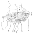
- Figures 1a to 1d show the hand-operated piston pump of the present invention, which is particularly intended for directional control of watercraft, boats or the like.
- the pump comprises a drive shaft 3, which is rotatably mounted in a housing case 1, a rotor 4 being mounted in the housing case 1.
- the rotor 4 is rotationally integral with the drive shaft 3 and has a plurality of axial compression chambers 104 formed in the body of the rotor 4, which surround the drive shaft 3.
- a piston 304 is axially slidably housed in each compression chamber 104 and is biased by elastic means 305, with one end projecting out of one end side of the corresponding compression chamber 104 against a cam track 8 consisting of an annular plate inclined with respect to the axis of rotation of the rotor 4.
- the pump further comprises a fluid reservoir 11 in the housing case 1, as well as a valve plate 6 located downstream from the rotor 4.
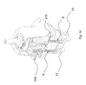
- the valve plate 6 has at least two separate conduits 106, 306, see Figures 2a and 2b , for the passage of pressurized fluid, which alternately communicate with conduits 204 for drawing/discharging the pressurized fluid, the latter conduits being provided in the bottom delimiting walls of the compression chambers 104 facing toward the valve plate 6.
- valve plate 6 is non-rotatably mounted below the housing case 1 and communicates with the conduits for supplying and returning the pressurized fluid to a consuming unit through an interposed check valve 28 inserted in a corresponding valve body 27, the latter having an upper flange 271, with fluid supply and return channels communicating with the fluid passage conduits 106, 306 of the valve plate 6.
- check valve may be fabricated as is known in the art, it will be fabricated according to the characteristics as described in EP 1382845 by the Applicant hereof.
- check valve prevents fluid from being supplied and discharged to the chambers of the steering actuator when the control member is still, and also affords a more efficient adjustment of supply thereto during steering.
- valve plate 6 is mounted to float relative to the upper flange 271.
- O-ring seals or the like 61 are interposed between the valve plate 6 and the upper flange 271 such that the valve plate 6 is separate from the upper flange 271.
- valve plate 6 is an independent part, which is non-rotatably mounted below the housing case 1 and above the upper flange 271.
- the upper flange 271 has at least two engagement teeth, not shown, which cooperate with corresponding engagement seats on the valve plate 6, to prevent any rotation of the plate.
- O-ring seals 121 may be also provided at the interface between the housing case 1 and the upper flange 271.
- valve body 27 and the upper flange 271 are made of one piece.
- a locking ring 7 is provided, which is fixed to the upper flange 271.
- the valve plate 6 is interposed between the locking ring 7 and the upper flange 271, such that the locking ring 7 may press against the seals 61 and that the valve plate 6 is mounted in contact with the locking ring 7 and separate from the upper flange 271.
- Figure 2b shows a section of the valve plate 6 and the locking ring 7 assembled together, as taken along a longitudinal plane.
- the section of the valve plate 6 has a L-shaped profile
- the locking ring 7 has a section with an inverted L-shaped profile
- the seals 61 are O-rings, said O-rings having a lobe shape.
- the seals are accommodated in corresponding lobe-shaped seats 62.
- the seats 62 may be formed in the thickness of the valve plate 6.
- these seats 62 may be formed in the thickness of the upper flange 271.
- two seals 61 are provided within two corresponding seats 62, which communicate with the fluid passage conduits 106, 306 formed in the valve plate 6 and with the fluid supply and return channels formed in the upper flange 271.
- the fluid passage conduits 106, 306 are placed at the center of each seat 62 and form a "tank" element which is filled with the fluid during operation of the pump.
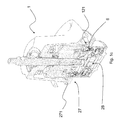
- the drive shaft 3 is disengaged from the rotor 4, an engagement member 31 being provided on the drive shaft 3, and engaging with a corresponding engagement seat 41 on the rotor 4.
- the engagement member 31 preferably consists of an element that radially extends from the lateral surface of the drive shaft 3, the engagement seat 41 consisting of a recess formed in the thickness of the lateral wall of the rotor 4, such that the drive shaft 3 and/or the rotor 4 are free to translate along their own longitudinal axis.
- the engagement member 31 is not formed of one piece with the drive shaft 3 but consists of a pin 31 which is housed in a receptacle formed in the drive shaft 31, engaging with the engagement seat 41.
- the pin 31 is "suspended", i.e. does not rest on the bottom of the engagement seat 41 formed in the rotor 4.
- Elastic elements may be provided in the engagement seat 41, for damping the movement of the pin, such that the pin is not allowed to contact the bottom of the engagement seat 41.
- a helical spring 32 is also provided coaxial with the drive shaft 3 and interposed between the rotor 4 and the housing case 1.
- the helical spring 32 allows adjustment of the relative movement of the drive shaft 3 - rotor 4 assembly, especially during mounting of the individual parts, as well as during oil purging.
- the helical spring 32 is compressed to a given extent.
- this spring 32 pushes the drive shaft 3 upwards and the rotor 4 downwards, while still maintaining the sealing effect, because the housing case 1 stops the movement of the drive shaft 3 upwards.
- the engagement seat 41 for the pin 31 has a depth that is much greater than its diameter and/or its section.
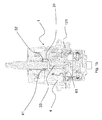
- Figure 1d shows the section of the pump of the present invention according to a possible embodiment, in which at least one, preferably two relief valves 9 are inserted in a seat formed in the thickness of the valve body 27.
- the relief valves allow the passage of fluid to the reservoir 11 as a given threshold pressure is reached in the delivery 12 and/or suction 13 ports of the pump.
- the fluid passes from the drawing/discharging conduits 204 in the bottom delimiting walls of the compression chambers 104 to the delivery 12 and/or suction 14 ports through the fluid passage conduits 106, 306 of the valve plate 6 and through the check valve 28.
- conduits 106, 306 communicate with the check valve 28 through two holes 279 of the upper flange 271.
- the relief valves 90 allow fluid to vent into the reservoir 11.
- the relief valves may be located in bodies with cylindrical symmetry, such as cans, inserted in the thickness of the wall of the valve body 27.
- the intake valves may be also inserted in a seat formed in the thickness of the valve body 27.
- the intake valves may be located in bodies with cylindrical symmetry, such as cans, inserted in the thickness of the wall of the valve body 27.
- vents may be provided in the various parts, for venting excess fluid, according to navigation conditions; as the drive shaft 3 is rotated, the piston 7 may push on an area filled with fluid, and such fluid should be vented to restore a normal drive feel.
- apertures may be preferably provided, for example on the valve plate 6, for the passage of excess fluid.
- the drive shaft 3 may also have fluid venting channels, for re-introducing excess fluid into the reservoir 11.
- These channels may be formed externally, i.e. on the outer surface of the drive shaft 3 or, like in the embodiment as shown in Figure 1a , the drive shaft 3 may have a longitudinal hole 33 formed therein over at least part of its length, and connected to a radial hole 34 in communication with the reservoir 11.
- the longitudinal hole 33 is threaded at least over a part of its length, at the end of the drive shaft 3 facing toward the valve plate 6.
Abstract
Description
- The present invention relates to a hand-operated piston pump, particularly for directional control of watercraft, boats or the like.
- The pump comprises a drive shaft, which is rotatably mounted in a housing case, a rotor, which is mounted in the housing case and is rotationally integral with the drive shaft, said rotor having a plurality of axial compression chambers formed in the body of the rotor.
- The axial compression chambers surround the drive shaft, a piston being axially slidably housed in each compression chamber and biased by elastic means, with one end projecting out of one end side of the corresponding compression chamber against a cam track consisting of an annular plate inclined with respect to the axis of rotation of the rotor.
- A fluid reservoir is also provided in the housing case.
- The pump further comprises a valve plate, which is located downstream from the rotor, in the direction of the fluid, particularly in the flow direction, and has at least two separate conduits for the passage of pressurized fluid, which alternately communicate with conduits for drawing/discharging the pressurized fluid, the latter conduits being provided in the bottom delimiting walls of the compression chambers facing toward the valve plate.
- Furthermore, the valve plate is non-rotatably mounted in the housing case, to communicate with the conduits for supplying and returning the pressurized fluid to a consuming unit, through an interposed check valve inserted in a corresponding valve body.
- The valve body has an upper flange, which has fluid supply and return channels communicating with the fluid passage conduits of the valve plate.
- Hand-operated pumps of this type are known and widely used in hydraulic steering control units, particularly for marine engines, especially outboard engines.
- The rotation of the drive shaft in either direction of rotation, e.g. by means of a steering wheel or a helm mounted thereto generates a displacement of the pressurized fluid in a closed-loop hydraulic circuit in either direction of rotation. The pressurized fluid is supplied from the check valve to each of the two inlets of a double-acting hydraulic cylinder respectively, the latter moving along a shaft which is held stationary between two fixed points connected at its ends, in one direction or in the opposite one, according to the direction of rotation of the drive shaft of the pump. The cylinder is in turn connected by a leverage system to a steering control element, for example of a marine outboard engine or to a rudder control lever.
- These prior art devices require high operational accuracy to ensure continuous, smooth operation, with no idle strokes, and repeatable steering settings. This reflects on pump construction, which must provide the required pressure differences on both conduits for connection to the double-acting hydraulic cylinder, in spite of a very low rpm, because the shaft is manually operated and the rotation speed and the stroke of the steering wheel shall ensure maximized comfort and reliability.
- Therefore, pumps are relatively complex and expensive, as they are composed of relatively complex parts, having complex conduits for the passage of the pressurized fluid.
- In prior art pumps, the valve plate is generally made of one piece with a closing base of the housing case, which consists of an overturned cup-shaped element having a central through hole for the end of the drive shaft to project therethrough and to be rotatably coupled to the steering wheel or the helm. The check valve is in turn sealing secured to such base. The manufacture of the valve plate, with the holes and ports for the passage of pressurized fluids, in a single construction piece, i.e. of one piece with the base, is generally relatively expensive both for the fabrication of the blank and for the required drilling of the passages for the pressurized fluid, as well as the additional finishing steps.
- A valve plate integrated with the base has a very high cost. Also, it will require the use of a material and a surface treatment that will both ensure hardness and durability and equally conform to the stainlessness requirements imposed on the base.
- The valve plate generally has two eccentric axial holes which open on the side of such valve plate that is associated to the rotor, into diametrically opposed radial recesses of the valve plate which extend to almost half of the section of the valve plate and are separated by a thin intermediate diametral partition.
- These holes and these recesses are also not easily formed, when the base is made of one piece with the valve plate. Furthermore, the base shall be also formed with various shapes and apertures for the passage of both the pressurized fluid and the screws that fasten it to the cup-shaped part, as well as for additional seats or receptacles, e.g. for the bearings that support the corresponding end of the rotor.
- As mentioned above, prior art piston pumps must be particularly efficient and provide immediate responses even to the slightest rotation angles of the control member.
- Due to these requirements, a high degree of accuracy is required for construction and assembly of the above mentioned parts, which will strongly impinge on manufacturing and maintenance costs for the pumps.
- Therefore, there exists a yet unfulfilled need in the art for a piston pump that can obviate the above described drawbacks of prior art pumps, particularly a piston pump that can provide the same efficiency as prior art pumps, while affording low manufacturing costs and easy construction.
- The present invention fulfills the above objects by providing a piston pump as described hereinbefore, in which the valve plate is mounted to float relative to the
upper flange 271, O-ring seals or the like being interposed between the valve plate and the upper flange, such that the valve plate is separate from the upper flange. - Therefore, the pump of the present invention uses a floating part, particularly the valve plate.
- In this case, lower construction accuracy requirements are imposed on the valve plate, as compared with prior art pumps, and costs are accordingly reduced.
- Since the valve plate is supported through two elastic seals, any overpressure occurring in the pump body may be more effectively compensated for.
- This is because the excess pressure of fluid causes the valve plate to press against the elastic seals and prevent any fluid leakage or spillage.
- The elastic behavior of the seals allows recovery of all construction tolerances.
- In a first embodiment a locking ring is provided, which is fixed to the upper flange, the valve plate being interposed between the locking ring and the upper flange, such that the locking ring presses against the seals.
- The valve plate is mounted in contact with the locking ring and separate from the upper flange.
- Therefore, the locking ring holds the valve plate pre-stressed against the seals to a well-defined extent, while allowing the seals for a residual elastic deformability, for the valve plate to be able to float relative to the upper flange.
- This will ensure a hydraulic sealing effect even under no load: for example, during filling and purging of the pump, a zero or quasi-zero pressure is generated, and this arrangement prevents the ingress of air from the outside.
- The locking ring may be fixed to the upper flange in any manner known in the art, for instance with screws arranged in different patterns, according to construction requirements.
- In order to optimize the thrust applied by the seals on the valve plate and the sealing action of the valve plate, and avoid spillage, the seals preferably consist of o-rings or the like, having a lobe-shape.
- In this embodiment, the seals are accommodated in corresponding lobe-shaped seats formed in the thickness of the valve plate and/or the thickness of the upper flange.
- Since the locking ring presses against the seals, this arrangement prevents the seals from accidentally coming off their seats.
- Advantageously, two seals are provided within two corresponding seats.
- The seats communicate with the fluid passage conduits in said valve plate and with the fluid supply and return channels in the upper flange.
- As more clearly shown in the exemplary embodiments that will be described below, if fluid also passes through the lobe-shaped seats, further compensation for overpressure is provided.
- In a preferred variant, the drive shaft is disengaged from the rotor.
- An engagement member is provided on the drive shaft, and engages with a corresponding engagement seat on the rotor.
- Thus, the drive shaft and/or the rotor are free to translate along their own longitudinal axis.
- The engagement member consists of an element that radially extends from the lateral surface of the drive shaft, and the engagement seat consists of a recess formed in the thickness of the lateral wall of the rotor.
- An elastic member is preferably provided in the form of a helical spring or the like, coaxial with the drive shaft and interposed between the rotor and the housing case.
- This arrangement will provide a pump that has more than one floating part, and the movement and settlement of the different parts will compensate for any clearance and inaccuracy resulting from the manufacture of each part.
- The provision of the engagement member allows the drive shaft to be disengaged from the rotor, and causes the shaft to drive the rotor into rotation, with the engagement member in the engaged state.
- Furthermore, when the pump is assembled, the helical spring is compressed to a given extent; such spring pushes the shaft against the reservoir and, at the same time, the rotor against the valve plate, thereby promoting a hydraulic sealing effect both during normal operation and during filling and purging of the pump. Without a perfect sealing effect, the rotor will tend to tilt and suck in air and the pump cannot be primed.
- Furthermore, the helical spring prevents the plate from rising up and air from flowing between the rotor and the plate.
- According to a possible embodiment, at least one relief valve is provided, which is inserted in a seat formed in the thickness of the valve body.
- This relief valve allows the passage of fluid to the reservoir as a given threshold pressure is reached in the delivery and/or suction ports of the pump.
- Preferably, the seat is a body with cylindrical symmetry, in the form of a can, which is inserted in the thickness of the wall of the valve body.
- This characteristic is particularly advantageous because the can is easily mounted and may be easily replaced in case of malfunctioning without damaging the entire pump.
- According to an improvement, the drive shaft has a longitudinal channel extending over at least part of its length, which is connected to a radial channel that communicates with the reservoir.
- The oil flow allowed by the channel formed in the drive shaft is used to relieve overpressure or remove excess oil if the pump is used with unbalanced cylinders.
- The channel may be formed anywhere in the drive shaft, e.g. on the outer surface thereof, but preferably the longitudinal channel consists of a longitudinal hole formed at the center axis of the shaft.
- Furthermore, the longitudinal hole is threaded at least over a part of its length, at the end of the drive shaft facing toward the valve plate.
- This improvement facilitates mounting and assembly of the various parts of the pump.
- Particularly, the above described characteristics will obviously impart modular features to the pump of the invention, allowing easy mounting and assembly of the various parts.
- Also, the concept that adds novelty and inventive step to the pump of the present invention, and makes it particularly advantageous as compared with prior art pumps is the provision of floating or semi-floating parts which might compensate for a low degree of accuracy in the construction of each part, thereby affording considerable savings.
- Thus, the present invention also relates to a pump as described in the preamble of claim 1, wherein the drive shaft is disengaged from the rotor, an engagement member being provided on the drive shaft, said engagement member engaging with a corresponding engagement seat on the rotor.
- The engagement member consists of an element that radially extends from the lateral surface of the drive shaft, and the engagement seat consists of a recess formed in the thickness of the lateral wall of the rotor, such that the drive shaft and/or the rotor are free to translate along their own longitudinal axis.
- A helical spring is also provided coaxial with the drive shaft and interposed between the rotor and the housing case.
- With this arrangement, both the drive shaft and the rotor are floating parts.
- The above described pump may be provided in combination with one or more of the above described characteristics.
- Finally, the present invention also relates to a steering device for vehicles, particularly boats or the like, consisting of a manual control member, such as a steering wheel or the like, which is connected to a drive shaft of a pressurized fluid supply and distribution unit, for manually driving the latter during rotation of the drive shaft.
- The supply and distribution unit consists of a piston pump, which is connected by its delivery and suction ports respectively and alternately to the two chambers of at least one steering actuator, such as a double-acting hydraulic cylinder or the like, through hydraulic conduits for alternately supplying fluid to either one of the two chambers of the actuator, according to the direction of movement, particularly rotation, of the control member.
- The piston pump is constructed according to one or more of the previously described characteristics, to be provided individually or in combination.
- These and other features and advantages of the present invention will appear more clearly from the following description of a few embodiments, illustrated in the annexed drawings, in which:
-
Figs. 1a to 1d show four sections of the pump of the present invention as taken along four different sectional planes; -
Figs. 2a and 2b show two different views of the valve plate in the piston pump of the present invention. - It should be noted that, while the figures annexed to the present application show a preferred embodiment of the pump of the present invention, these figures shall be only intended by way of illustration, for a better understanding of the concepts and advantages of the present invention.
- Thus, these figures shall not be intended to limit the guiding principle as claimed in this patent application, i.e. the provision of a pump having floating parts.
-
Figures 1a to 1d show the hand-operated piston pump of the present invention, which is particularly intended for directional control of watercraft, boats or the like. - The pump comprises a drive shaft 3, which is rotatably mounted in a housing case 1, a rotor 4 being mounted in the housing case 1.
- The rotor 4 is rotationally integral with the drive shaft 3 and has a plurality of
axial compression chambers 104 formed in the body of the rotor 4, which surround the drive shaft 3. - A
piston 304 is axially slidably housed in eachcompression chamber 104 and is biased byelastic means 305, with one end projecting out of one end side of the correspondingcompression chamber 104 against acam track 8 consisting of an annular plate inclined with respect to the axis of rotation of the rotor 4. - The pump further comprises a
fluid reservoir 11 in the housing case 1, as well as avalve plate 6 located downstream from the rotor 4. - The
valve plate 6 has at least twoseparate conduits Figures 2a and 2b , for the passage of pressurized fluid, which alternately communicate withconduits 204 for drawing/discharging the pressurized fluid, the latter conduits being provided in the bottom delimiting walls of thecompression chambers 104 facing toward thevalve plate 6. - Furthermore, the
valve plate 6 is non-rotatably mounted below the housing case 1 and communicates with the conduits for supplying and returning the pressurized fluid to a consuming unit through an interposedcheck valve 28 inserted in acorresponding valve body 27, the latter having anupper flange 271, with fluid supply and return channels communicating with thefluid passage conduits valve plate 6. - It shall be noted that while the check valve may be fabricated as is known in the art, it will be fabricated according to the characteristics as described in
EP 1382845 by the Applicant hereof. - The use of the check valve prevents fluid from being supplied and discharged to the chambers of the steering actuator when the control member is still, and also affords a more efficient adjustment of supply thereto during steering.
- Particularly, the
valve plate 6 is mounted to float relative to theupper flange 271. - O-ring seals or the like 61 are interposed between the
valve plate 6 and theupper flange 271 such that thevalve plate 6 is separate from theupper flange 271. - Therefore, the
valve plate 6 is an independent part, which is non-rotatably mounted below the housing case 1 and above theupper flange 271. - Preferably, the
upper flange 271 has at least two engagement teeth, not shown, which cooperate with corresponding engagement seats on thevalve plate 6, to prevent any rotation of the plate. - Particularly referring to
Figure 1a , O-ring seals 121 may be also provided at the interface between the housing case 1 and theupper flange 271. - Also preferably, the
valve body 27 and theupper flange 271 are made of one piece. - According to the variant embodiment of the figures, a
locking ring 7 is provided, which is fixed to theupper flange 271. - The
valve plate 6 is interposed between the lockingring 7 and theupper flange 271, such that thelocking ring 7 may press against theseals 61 and that thevalve plate 6 is mounted in contact with thelocking ring 7 and separate from theupper flange 271. -
Figure 2b shows a section of thevalve plate 6 and thelocking ring 7 assembled together, as taken along a longitudinal plane. - In the variant of
Figure 2b , the section of thevalve plate 6 has a L-shaped profile, whereas thelocking ring 7 has a section with an inverted L-shaped profile. - This configuration optimizing the sealing action of the
locking ring 7 toward thevalve plate 6, while limiting the thickness of the pump and optimizing its size. - As shown in
Figure 2a , theseals 61 are O-rings, said O-rings having a lobe shape. - Particularly, the seals are accommodated in corresponding lobe-shaped
seats 62. - Particularly referring to
Figure 2a , theseats 62 may be formed in the thickness of thevalve plate 6. - In one embodiment, these
seats 62 may be formed in the thickness of theupper flange 271. - Preferably, according to the illustrated variant embodiment, two
seals 61 are provided within two correspondingseats 62, which communicate with thefluid passage conduits valve plate 6 and with the fluid supply and return channels formed in theupper flange 271. - Particularly, the
fluid passage conduits seat 62 and form a "tank" element which is filled with the fluid during operation of the pump. - Referring to
Figure 1b , the drive shaft 3 is disengaged from the rotor 4, anengagement member 31 being provided on the drive shaft 3, and engaging with acorresponding engagement seat 41 on the rotor 4. - The
engagement member 31 preferably consists of an element that radially extends from the lateral surface of the drive shaft 3, theengagement seat 41 consisting of a recess formed in the thickness of the lateral wall of the rotor 4, such that the drive shaft 3 and/or the rotor 4 are free to translate along their own longitudinal axis. - Preferably, the
engagement member 31 is not formed of one piece with the drive shaft 3 but consists of apin 31 which is housed in a receptacle formed in thedrive shaft 31, engaging with theengagement seat 41. - In order to allow longitudinal translation of the drive shaft 3 and the rotor 4, the
pin 31 is "suspended", i.e. does not rest on the bottom of theengagement seat 41 formed in the rotor 4. - Elastic elements may be provided in the
engagement seat 41, for damping the movement of the pin, such that the pin is not allowed to contact the bottom of theengagement seat 41. - A
helical spring 32 is also provided coaxial with the drive shaft 3 and interposed between the rotor 4 and the housing case 1. - The
helical spring 32 allows adjustment of the relative movement of the drive shaft 3 - rotor 4 assembly, especially during mounting of the individual parts, as well as during oil purging. - During pump assembly, the
helical spring 32 is compressed to a given extent. - In this configuration, when the housing case 1 is mounted, the
pin 31 moves downwards, and remains suspended at about the middle theengagement seat 41. - According to the pre-load of the
helical spring 32, thisspring 32 pushes the drive shaft 3 upwards and the rotor 4 downwards, while still maintaining the sealing effect, because the housing case 1 stops the movement of the drive shaft 3 upwards. - For the force of the
helical spring 32 to be properly discharged between the housing case 1 and the rotor 4, theengagement seat 41 for thepin 31 has a depth that is much greater than its diameter and/or its section. -
Figure 1d shows the section of the pump of the present invention according to a possible embodiment, in which at least one, preferably tworelief valves 9 are inserted in a seat formed in the thickness of thevalve body 27. - The relief valves allow the passage of fluid to the
reservoir 11 as a given threshold pressure is reached in thedelivery 12 and/orsuction 13 ports of the pump. - Particularly referring to
Figures 1a to 1d , the fluid passes from the drawing/dischargingconduits 204 in the bottom delimiting walls of thecompression chambers 104 to thedelivery 12 and/or suction 14 ports through thefluid passage conduits valve plate 6 and through thecheck valve 28. - Particularly, the
conduits check valve 28 through twoholes 279 of theupper flange 271. - If high pressure is reached in the
delivery 12 and/orsuction 13 ports, the relief valves 90 allow fluid to vent into thereservoir 11. - As shown in
Figure 1d , the relief valves may be located in bodies with cylindrical symmetry, such as cans, inserted in the thickness of the wall of thevalve body 27. - These cans allow the provision of "self-standing" relief valves, which may be inserted from the back of the pump, i.e. the bottom, irrespective of the construction of the
valve body 27. - Like the relief valves, the intake valves may be also inserted in a seat formed in the thickness of the
valve body 27. - The intake valves may be located in bodies with cylindrical symmetry, such as cans, inserted in the thickness of the wall of the
valve body 27. - Finally, several vents may be provided in the various parts, for venting excess fluid, according to navigation conditions; as the drive shaft 3 is rotated, the
piston 7 may push on an area filled with fluid, and such fluid should be vented to restore a normal drive feel. - Therefore, apertures may be preferably provided, for example on the
valve plate 6, for the passage of excess fluid. - The drive shaft 3 may also have fluid venting channels, for re-introducing excess fluid into the
reservoir 11. - These channels may be formed externally, i.e. on the outer surface of the drive shaft 3 or, like in the embodiment as shown in
Figure 1a , the drive shaft 3 may have alongitudinal hole 33 formed therein over at least part of its length, and connected to aradial hole 34 in communication with thereservoir 11. - Preferably, the
longitudinal hole 33 is threaded at least over a part of its length, at the end of the drive shaft 3 facing toward thevalve plate 6.
Claims (11)
- A hand-operated piston pump, particularly for directional control of watercrafts, boats or the like, said pump comprising:a drive shaft (3), which is rotatably mounted in a housing case (1),a rotor (4), which is mounted in the housing case (1) and is rotationally integral with the drive shaft (3), said rotor (4) having a plurality of axial compression chambers (104) formed in the body of said rotor (4), said axial compression chambers (104) surrounding the drive shaft (3), a piston (304) being axially slidably housed in each compression chamber (104) and biased by elastic means, with one end projecting out of one end side of the corresponding compression chamber (104) against a cam track (8) consisting of an annular plate inclined with respect to the axis of rotation of said rotor (4),a fluid reservoir in said housing case (1),a valve plate (6) located downstream from said rotor (4) and having at least two separate conduits (106, 306) for the passage of pressurized fluid, which alternately communicate with conduits (204) for drawing/discharging said pressurized fluid, the latter conduits being provided in the bottom delimiting walls of said compression chambers (104) facing toward said valve plate (6),said valve plate (6) being non-rotatably mounted below said housing case (1)and said valve plate (6) communicating with conduits for supplying and returning the pressurized fluid to a consuming unit through an interposed check valve (28) inserted in a corresponding valve body (27), said valve body (27) having an upper flange (271), said upper flange having fluid supply and return channels communicating with said fluid passage conduits (106, 306) of said valve plate,characterized in thatsaid valve plate (6) is mounted to float relative to said upper flange (271), O-ring seals or the like being interposed between said valve plate (6) and said upper flange (271), such that said valve plate (6) is separate from said upper flange (271).
- A piston pump as claimed in claim 1, wherein a locking ring is provided, which is fixed to said upper flange (271), said valve plate (6) being interposed between said locking ring and said upper flange (271), such that said locking ring presses said seals,
said valve plate being mounted in contact with said locking ring and separate from said upper flange (271). - A piston pump as claimed in claim 1, wherein said seals are O-rings or the like, said O-rings having a lobe shape,
said seals being accommodated in corresponding lobe-shaped seats formed in the thickness of said valve plate (6) and/or the thickness of said upper flange (271). - A piston pump as claimed in claim 3, wherein two seals are provided within two corresponding seats, which seats communicate with said fluid passage conduits (106, 306) in said valve plate (6) and with said fluid supply and return channels in said upper flange (271).
- A piston pump as claimed in claim 1, wherein said drive shaft (3) is disengaged from said rotor (4), an engagement member being provided on said drive shaft (3), said engagement member engaging with a corresponding engagement seat on said rotor (4),
said engagement member (31) consisting of an element that radially extends from the lateral surface of said drive shaft (3), and said engagement seat (41) consisting of a recess formed in the thickness of the lateral wall of said rotor (4), such that said drive shaft (3) and/or said rotor (4) are free to translate along their own longitudinal axis,
an elastic member being provided in the form of a helical spring coaxial with said drive shaft (3) and interposed between said rotor (4) and said housing case (1). - A piston pump as claimed in claim 1, wherein at least one relief valve is provided, said relief valve being inserted in a seat formed in the thickness of said valve body (27),
said relief valve allowing the passage of fluid to the reservoir as a given threshold pressure is reached in the delivery and/or suction ports of said pump. - A piston pump as claimed in claim 1, wherein said drive shaft (3) has a longitudinal channel extending over at least part of its length, which longitudinal channel is connected to a radial cannel that communicates with said reservoir.
- A piston pump as claimed in claim 7, wherein said longitudinal channel consists of a longitudinal hole formed at the center axis of said shaft, said longitudinal hole being threaded at least over a part of its length, at the end of said drive shaft (3) toward said valve plate (6).
- A hand-operated piston pump, particularly for directional control of watercrafts, boats or the like, said pump comprising:a drive shaft (3), which is rotatably mounted in a housing case (1),a rotor (4), which is mounted in the housing case (1) and is rotationally integral with the drive shaft (3), said rotor (4) having a plurality of axial compression chambers (104) formed in the body of said rotor (4), said axial compression chambers (104) surrounding the drive shaft (3), a piston (304) being axially slidably housed in each compression chamber (104) and biased by elastic means, with one end projecting out of one end side of the corresponding compression chamber (104) against a cam track (8) consisting of an annular plate inclined with respect to the axis of rotation of said rotor (4),a fluid reservoir in said housing case (1),a valve plate (6) located downstream from said rotor (4) and having at least two separate conduits (106, 306) for the passage of pressurized fluid, which alternately communicate with conduits (204) for drawing/discharging said pressurized fluid, the latter conduits being provided in the bottom delimiting walls of said compression chambers (104) facing toward said valve plate (6),said valve plate (6) being non-rotatably mounted below said housing case (1)and said valve plate (6) communicating with conduits for supplying and returning the pressurized fluid to a consuming unit through an interposed check valve (28) inserted in a corresponding valve body (27), said valve body (27) having an upper flange (271), said upper flange having fluid supply and return channels communicating with said fluid passage conduits (106, 306) of said valve plate,characterized in thatsaid drive shaft (3) is disengaged from said rotor (4), an engagement member being provided on said drive shaft (3), said engagement member engaging with a corresponding engagement seat on said rotor (4),said engagement member consisting of an element that radially extends from the lateral surface of said drive shaft (3), and said engagement seat consisting of a recess formed in the thickness of the lateral wall of said rotor (4), such that said drive shaft (3) and/or said rotor (4) are free to translate along their own longitudinal axis,a helical spring being provided coaxial with said drive shaft (3) and interposed between said rotor (4) and said housing case (1).
- A piston pump as claimed in claim 9, having one or more of the features of claims 1 to 8.
- A steering device for vehicles, particularly boats or the like, consisting of a manual control member (11), such as a steering wheel or the like, said manual control member (11) being connected to a drive shaft (3) of a pressurized fluid supply and distribution unit, for manually driving the latter during rotation of the drive shaft (3), which supply and distribution unit consists of a piston pump,
said piston pump being connected by their delivery and suction ports respectively and alternately to the two chambers of at least one steering actuator, such as a double-acting hydraulic cylinder or the like, through hydraulic conduits for alternately supplying fluid to either one of said two chambers of said at least one actuator, according to the direction of movement, particularly rotation, of the control member,
characterized in that
said piston pump is formed as claimed in one or more of the features of claims 1 to 10.
Applications Claiming Priority (1)
| Application Number | Priority Date | Filing Date | Title |
|---|---|---|---|
| IT000088A ITGE20130088A1 (en) | 2013-09-16 | 2013-09-16 | PLASTIC PUMP |
Publications (3)
| Publication Number | Publication Date |
|---|---|
| EP2857680A2 true EP2857680A2 (en) | 2015-04-08 |
| EP2857680A3 EP2857680A3 (en) | 2015-12-02 |
| EP2857680B1 EP2857680B1 (en) | 2016-11-09 |
Family
ID=49585503
Family Applications (1)
| Application Number | Title | Priority Date | Filing Date |
|---|---|---|---|
| EP14184661.8A Active EP2857680B1 (en) | 2013-09-16 | 2014-09-12 | Hand-operated piston pump |
Country Status (3)
| Country | Link |
|---|---|
| US (1) | US9676465B2 (en) |
| EP (1) | EP2857680B1 (en) |
| IT (1) | ITGE20130088A1 (en) |
Cited By (1)
| Publication number | Priority date | Publication date | Assignee | Title |
|---|---|---|---|---|
| IT201900015042A1 (en) | 2019-08-26 | 2021-02-26 | Ultraflex Spa | Hydraulic steering device for boats, boats or similar |
Families Citing this family (3)
| Publication number | Priority date | Publication date | Assignee | Title |
|---|---|---|---|---|
| CN105526052A (en) * | 2015-12-09 | 2016-04-27 | 沈阳飞研航空设备有限公司 | High pressure manual pump |
| ITUB20160875A1 (en) | 2016-02-19 | 2017-08-19 | Ultraflex Spa | Boat steering control device |
| CN112141311B (en) * | 2020-09-25 | 2022-02-25 | 山东交通学院 | Marine hydraulic steering engine for laying dredging robot |
Citations (1)
| Publication number | Priority date | Publication date | Assignee | Title |
|---|---|---|---|---|
| EP1382845A2 (en) | 2002-07-16 | 2004-01-21 | ULTRAFLEX S.p.A. | Oil pump for marine steering gear |
Family Cites Families (5)
| Publication number | Priority date | Publication date | Assignee | Title |
|---|---|---|---|---|
| US3209541A (en) * | 1963-07-29 | 1965-10-05 | William P Dunphy | Hydraulic remote control apparatus |
| DE1653461A1 (en) * | 1967-03-14 | 1971-07-29 | Martin Herter | Axial piston pump or motor |
| GB1199600A (en) * | 1967-12-13 | 1970-07-22 | Kopat Ges Fur Konstruktion Ent | Improvements in Axial Piston Units |
| US3566746A (en) * | 1969-04-29 | 1971-03-02 | Nemo Corp | Hydraulic steering system for boats |
| DE1939297A1 (en) * | 1969-08-01 | 1971-02-11 | Linde Ag | Axial piston machine |
-
2013
- 2013-09-16 IT IT000088A patent/ITGE20130088A1/en unknown
-
2014
- 2014-09-12 US US14/485,369 patent/US9676465B2/en active Active
- 2014-09-12 EP EP14184661.8A patent/EP2857680B1/en active Active
Patent Citations (1)
| Publication number | Priority date | Publication date | Assignee | Title |
|---|---|---|---|---|
| EP1382845A2 (en) | 2002-07-16 | 2004-01-21 | ULTRAFLEX S.p.A. | Oil pump for marine steering gear |
Cited By (2)
| Publication number | Priority date | Publication date | Assignee | Title |
|---|---|---|---|---|
| IT201900015042A1 (en) | 2019-08-26 | 2021-02-26 | Ultraflex Spa | Hydraulic steering device for boats, boats or similar |
| EP3786053A1 (en) | 2019-08-26 | 2021-03-03 | Ultraflex Spa | Hydraulic steering device for boats, vessels or the like |
Also Published As
| Publication number | Publication date |
|---|---|
| EP2857680A3 (en) | 2015-12-02 |
| US9676465B2 (en) | 2017-06-13 |
| ITGE20130088A1 (en) | 2015-03-17 |
| EP2857680B1 (en) | 2016-11-09 |
| US20150075158A1 (en) | 2015-03-19 |
Similar Documents
| Publication | Publication Date | Title |
|---|---|---|
| EP2857680B1 (en) | Hand-operated piston pump | |
| KR20110028299A (en) | Piston pump of a hydraulic vehicle brake system | |
| US10738690B2 (en) | Connecting rod having an adjustable connecting rod length with a mechanical actuating means | |
| US7055317B2 (en) | Hydraulic module | |
| US6896093B2 (en) | Integral power steering apparatus | |
| US20190048870A1 (en) | Piston Pump, in particular as a Pressure Generator in an Electronically Slip-Controllable Vehicle Brake System | |
| CN101449062A (en) | Screw compressor comprising a relief valve | |
| US6984113B2 (en) | Oil pressure operated pump for marine steering gears with a valve set shell with valves separately capable of assembly with the valve housing | |
| US5081907A (en) | Hydrostatic displacement engine | |
| KR102653718B1 (en) | Panic valve integrated into the pivot pin of the pump | |
| US4642032A (en) | Axial piston pump including ball piston | |
| CN108331792B (en) | Hydraulic module for controlling the hydraulic fluid flow of a connecting rod of an internal combustion engine with variable compression ratio, and connecting rod | |
| US5466130A (en) | Helm pump | |
| US6682315B2 (en) | Axial piston pump barrel with a cast high pressure collection cavity | |
| US4407640A (en) | Reciprocating pump having unique pressure control valve construction | |
| AU2007271190B2 (en) | Hydraulic pump | |
| US3172368A (en) | Pump | |
| JPH07238883A (en) | Plunger pump | |
| JPH09195926A (en) | Radial plunger pump | |
| RU2702830C1 (en) | Pump | |
| JP6932885B2 (en) | Hydraulic cylinder device | |
| WO2017187228A1 (en) | Hydraulic pump with isolated commutator | |
| KR20200062295A (en) | Booster | |
| KR20170003666U (en) | Volume adjustable internal gear pump | |
| JPH0530471U (en) | Plunger pump |
Legal Events
| Date | Code | Title | Description |
|---|---|---|---|
| PUAI | Public reference made under article 153(3) epc to a published international application that has entered the european phase |
Free format text: ORIGINAL CODE: 0009012 |
|
| 17P | Request for examination filed |
Effective date: 20140912 |
|
| AK | Designated contracting states |
Kind code of ref document: A2 Designated state(s): AL AT BE BG CH CY CZ DE DK EE ES FI FR GB GR HR HU IE IS IT LI LT LU LV MC MK MT NL NO PL PT RO RS SE SI SK SM TR |
|
| AX | Request for extension of the european patent |
Extension state: BA ME |
|
| PUAL | Search report despatched |
Free format text: ORIGINAL CODE: 0009013 |
|
| AK | Designated contracting states |
Kind code of ref document: A3 Designated state(s): AL AT BE BG CH CY CZ DE DK EE ES FI FR GB GR HR HU IE IS IT LI LT LU LV MC MK MT NL NO PL PT RO RS SE SI SK SM TR |
|
| AX | Request for extension of the european patent |
Extension state: BA ME |
|
| RIC1 | Information provided on ipc code assigned before grant |
Ipc: F04B 1/20 20060101ALI20150623BHEP Ipc: F01B 3/00 20060101ALI20150623BHEP Ipc: F04B 9/14 20060101AFI20150623BHEP |
|
| PUAF | Information related to the publication of a search report (a3 document) modified or deleted |
Free format text: ORIGINAL CODE: 0009199SEPU |
|
| D17D | Deferred search report published (deleted) | ||
| PUAL | Search report despatched |
Free format text: ORIGINAL CODE: 0009013 |
|
| AK | Designated contracting states |
Kind code of ref document: A3 Designated state(s): AL AT BE BG CH CY CZ DE DK EE ES FI FR GB GR HR HU IE IS IT LI LT LU LV MC MK MT NL NO PL PT RO RS SE SI SK SM TR |
|
| AX | Request for extension of the european patent |
Extension state: BA ME |
|
| RIC1 | Information provided on ipc code assigned before grant |
Ipc: B63H 25/22 20060101ALI20151029BHEP Ipc: F04B 1/20 20060101ALI20151029BHEP Ipc: F01B 3/00 20060101ALI20151029BHEP Ipc: F04B 9/14 20060101AFI20151029BHEP |
|
| GRAP | Despatch of communication of intention to grant a patent |
Free format text: ORIGINAL CODE: EPIDOSNIGR1 |
|
| R17P | Request for examination filed (corrected) |
Effective date: 20160530 |
|
| RBV | Designated contracting states (corrected) |
Designated state(s): AL AT BE BG CH CY CZ DE DK EE ES FI FR GB GR HR HU IE IS IT LI LT LU LV MC MK MT NL NO PL PT RO RS SE SI SK SM TR |
|
| INTG | Intention to grant announced |
Effective date: 20160701 |
|
| GRAS | Grant fee paid |
Free format text: ORIGINAL CODE: EPIDOSNIGR3 |
|
| GRAA | (expected) grant |
Free format text: ORIGINAL CODE: 0009210 |
|
| AK | Designated contracting states |
Kind code of ref document: B1 Designated state(s): AL AT BE BG CH CY CZ DE DK EE ES FI FR GB GR HR HU IE IS IT LI LT LU LV MC MK MT NL NO PL PT RO RS SE SI SK SM TR |
|
| REG | Reference to a national code |
Ref country code: GB Ref legal event code: FG4D |
|
| REG | Reference to a national code |
Ref country code: AT Ref legal event code: REF Ref document number: 844184 Country of ref document: AT Kind code of ref document: T Effective date: 20161115 Ref country code: CH Ref legal event code: EP |
|
| REG | Reference to a national code |
Ref country code: IE Ref legal event code: FG4D |
|
| REG | Reference to a national code |
Ref country code: DE Ref legal event code: R096 Ref document number: 602014004715 Country of ref document: DE |
|
| PG25 | Lapsed in a contracting state [announced via postgrant information from national office to epo] |
Ref country code: LV Free format text: LAPSE BECAUSE OF FAILURE TO SUBMIT A TRANSLATION OF THE DESCRIPTION OR TO PAY THE FEE WITHIN THE PRESCRIBED TIME-LIMIT Effective date: 20161109 |
|
| REG | Reference to a national code |
Ref country code: LT Ref legal event code: MG4D |
|
| REG | Reference to a national code |
Ref country code: NL Ref legal event code: MP Effective date: 20161109 |
|
| REG | Reference to a national code |
Ref country code: AT Ref legal event code: MK05 Ref document number: 844184 Country of ref document: AT Kind code of ref document: T Effective date: 20161109 |
|
| PG25 | Lapsed in a contracting state [announced via postgrant information from national office to epo] |
Ref country code: LT Free format text: LAPSE BECAUSE OF FAILURE TO SUBMIT A TRANSLATION OF THE DESCRIPTION OR TO PAY THE FEE WITHIN THE PRESCRIBED TIME-LIMIT Effective date: 20161109 Ref country code: NL Free format text: LAPSE BECAUSE OF FAILURE TO SUBMIT A TRANSLATION OF THE DESCRIPTION OR TO PAY THE FEE WITHIN THE PRESCRIBED TIME-LIMIT Effective date: 20161109 Ref country code: GR Free format text: LAPSE BECAUSE OF FAILURE TO SUBMIT A TRANSLATION OF THE DESCRIPTION OR TO PAY THE FEE WITHIN THE PRESCRIBED TIME-LIMIT Effective date: 20170210 Ref country code: SE Free format text: LAPSE BECAUSE OF FAILURE TO SUBMIT A TRANSLATION OF THE DESCRIPTION OR TO PAY THE FEE WITHIN THE PRESCRIBED TIME-LIMIT Effective date: 20161109 Ref country code: NO Free format text: LAPSE BECAUSE OF FAILURE TO SUBMIT A TRANSLATION OF THE DESCRIPTION OR TO PAY THE FEE WITHIN THE PRESCRIBED TIME-LIMIT Effective date: 20170209 |
|
| PG25 | Lapsed in a contracting state [announced via postgrant information from national office to epo] |
Ref country code: IS Free format text: LAPSE BECAUSE OF FAILURE TO SUBMIT A TRANSLATION OF THE DESCRIPTION OR TO PAY THE FEE WITHIN THE PRESCRIBED TIME-LIMIT Effective date: 20170309 Ref country code: FI Free format text: LAPSE BECAUSE OF FAILURE TO SUBMIT A TRANSLATION OF THE DESCRIPTION OR TO PAY THE FEE WITHIN THE PRESCRIBED TIME-LIMIT Effective date: 20161109 Ref country code: RS Free format text: LAPSE BECAUSE OF FAILURE TO SUBMIT A TRANSLATION OF THE DESCRIPTION OR TO PAY THE FEE WITHIN THE PRESCRIBED TIME-LIMIT Effective date: 20161109 Ref country code: PL Free format text: LAPSE BECAUSE OF FAILURE TO SUBMIT A TRANSLATION OF THE DESCRIPTION OR TO PAY THE FEE WITHIN THE PRESCRIBED TIME-LIMIT Effective date: 20161109 Ref country code: ES Free format text: LAPSE BECAUSE OF FAILURE TO SUBMIT A TRANSLATION OF THE DESCRIPTION OR TO PAY THE FEE WITHIN THE PRESCRIBED TIME-LIMIT Effective date: 20161109 Ref country code: PT Free format text: LAPSE BECAUSE OF FAILURE TO SUBMIT A TRANSLATION OF THE DESCRIPTION OR TO PAY THE FEE WITHIN THE PRESCRIBED TIME-LIMIT Effective date: 20170309 Ref country code: AT Free format text: LAPSE BECAUSE OF FAILURE TO SUBMIT A TRANSLATION OF THE DESCRIPTION OR TO PAY THE FEE WITHIN THE PRESCRIBED TIME-LIMIT Effective date: 20161109 Ref country code: HR Free format text: LAPSE BECAUSE OF FAILURE TO SUBMIT A TRANSLATION OF THE DESCRIPTION OR TO PAY THE FEE WITHIN THE PRESCRIBED TIME-LIMIT Effective date: 20161109 |
|
| PG25 | Lapsed in a contracting state [announced via postgrant information from national office to epo] |
Ref country code: RO Free format text: LAPSE BECAUSE OF FAILURE TO SUBMIT A TRANSLATION OF THE DESCRIPTION OR TO PAY THE FEE WITHIN THE PRESCRIBED TIME-LIMIT Effective date: 20161109 Ref country code: CZ Free format text: LAPSE BECAUSE OF FAILURE TO SUBMIT A TRANSLATION OF THE DESCRIPTION OR TO PAY THE FEE WITHIN THE PRESCRIBED TIME-LIMIT Effective date: 20161109 Ref country code: SK Free format text: LAPSE BECAUSE OF FAILURE TO SUBMIT A TRANSLATION OF THE DESCRIPTION OR TO PAY THE FEE WITHIN THE PRESCRIBED TIME-LIMIT Effective date: 20161109 Ref country code: DK Free format text: LAPSE BECAUSE OF FAILURE TO SUBMIT A TRANSLATION OF THE DESCRIPTION OR TO PAY THE FEE WITHIN THE PRESCRIBED TIME-LIMIT Effective date: 20161109 Ref country code: EE Free format text: LAPSE BECAUSE OF FAILURE TO SUBMIT A TRANSLATION OF THE DESCRIPTION OR TO PAY THE FEE WITHIN THE PRESCRIBED TIME-LIMIT Effective date: 20161109 |
|
| REG | Reference to a national code |
Ref country code: DE Ref legal event code: R097 Ref document number: 602014004715 Country of ref document: DE |
|
| REG | Reference to a national code |
Ref country code: FR Ref legal event code: PLFP Year of fee payment: 4 |
|
| PG25 | Lapsed in a contracting state [announced via postgrant information from national office to epo] |
Ref country code: BG Free format text: LAPSE BECAUSE OF FAILURE TO SUBMIT A TRANSLATION OF THE DESCRIPTION OR TO PAY THE FEE WITHIN THE PRESCRIBED TIME-LIMIT Effective date: 20170209 Ref country code: IT Free format text: LAPSE BECAUSE OF FAILURE TO SUBMIT A TRANSLATION OF THE DESCRIPTION OR TO PAY THE FEE WITHIN THE PRESCRIBED TIME-LIMIT Effective date: 20161109 Ref country code: BE Free format text: LAPSE BECAUSE OF FAILURE TO SUBMIT A TRANSLATION OF THE DESCRIPTION OR TO PAY THE FEE WITHIN THE PRESCRIBED TIME-LIMIT Effective date: 20161109 Ref country code: SM Free format text: LAPSE BECAUSE OF FAILURE TO SUBMIT A TRANSLATION OF THE DESCRIPTION OR TO PAY THE FEE WITHIN THE PRESCRIBED TIME-LIMIT Effective date: 20161109 |
|
| PLBE | No opposition filed within time limit |
Free format text: ORIGINAL CODE: 0009261 |
|
| STAA | Information on the status of an ep patent application or granted ep patent |
Free format text: STATUS: NO OPPOSITION FILED WITHIN TIME LIMIT |
|
| 26N | No opposition filed |
Effective date: 20170810 |
|
| PGFP | Annual fee paid to national office [announced via postgrant information from national office to epo] |
Ref country code: CH Payment date: 20170831 Year of fee payment: 4 Ref country code: DE Payment date: 20170830 Year of fee payment: 4 Ref country code: LU Payment date: 20170901 Year of fee payment: 4 Ref country code: MC Payment date: 20170904 Year of fee payment: 4 |
|
| PG25 | Lapsed in a contracting state [announced via postgrant information from national office to epo] |
Ref country code: SI Free format text: LAPSE BECAUSE OF FAILURE TO SUBMIT A TRANSLATION OF THE DESCRIPTION OR TO PAY THE FEE WITHIN THE PRESCRIBED TIME-LIMIT Effective date: 20161109 |
|
| PGFP | Annual fee paid to national office [announced via postgrant information from national office to epo] |
Ref country code: IE Payment date: 20170830 Year of fee payment: 4 |
|
| PG25 | Lapsed in a contracting state [announced via postgrant information from national office to epo] |
Ref country code: MT Free format text: LAPSE BECAUSE OF NON-PAYMENT OF DUE FEES Effective date: 20170912 |
|
| REG | Reference to a national code |
Ref country code: FR Ref legal event code: PLFP Year of fee payment: 5 |
|
| REG | Reference to a national code |
Ref country code: DE Ref legal event code: R119 Ref document number: 602014004715 Country of ref document: DE |
|
| PG25 | Lapsed in a contracting state [announced via postgrant information from national office to epo] |
Ref country code: MC Free format text: LAPSE BECAUSE OF NON-PAYMENT OF DUE FEES Effective date: 20181001 |
|
| REG | Reference to a national code |
Ref country code: CH Ref legal event code: PL |
|
| REG | Reference to a national code |
Ref country code: IE Ref legal event code: MM4A |
|
| PG25 | Lapsed in a contracting state [announced via postgrant information from national office to epo] |
Ref country code: HU Free format text: LAPSE BECAUSE OF FAILURE TO SUBMIT A TRANSLATION OF THE DESCRIPTION OR TO PAY THE FEE WITHIN THE PRESCRIBED TIME-LIMIT; INVALID AB INITIO Effective date: 20140912 Ref country code: LU Free format text: LAPSE BECAUSE OF NON-PAYMENT OF DUE FEES Effective date: 20180912 |
|
| PG25 | Lapsed in a contracting state [announced via postgrant information from national office to epo] |
Ref country code: DE Free format text: LAPSE BECAUSE OF NON-PAYMENT OF DUE FEES Effective date: 20190402 Ref country code: IE Free format text: LAPSE BECAUSE OF NON-PAYMENT OF DUE FEES Effective date: 20180912 |
|
| PG25 | Lapsed in a contracting state [announced via postgrant information from national office to epo] |
Ref country code: LI Free format text: LAPSE BECAUSE OF NON-PAYMENT OF DUE FEES Effective date: 20180930 Ref country code: CH Free format text: LAPSE BECAUSE OF NON-PAYMENT OF DUE FEES Effective date: 20180930 |
|
| PG25 | Lapsed in a contracting state [announced via postgrant information from national office to epo] |
Ref country code: CY Free format text: LAPSE BECAUSE OF FAILURE TO SUBMIT A TRANSLATION OF THE DESCRIPTION OR TO PAY THE FEE WITHIN THE PRESCRIBED TIME-LIMIT Effective date: 20161109 |
|
| PG25 | Lapsed in a contracting state [announced via postgrant information from national office to epo] |
Ref country code: MK Free format text: LAPSE BECAUSE OF FAILURE TO SUBMIT A TRANSLATION OF THE DESCRIPTION OR TO PAY THE FEE WITHIN THE PRESCRIBED TIME-LIMIT Effective date: 20161109 |
|
| PG25 | Lapsed in a contracting state [announced via postgrant information from national office to epo] |
Ref country code: TR Free format text: LAPSE BECAUSE OF FAILURE TO SUBMIT A TRANSLATION OF THE DESCRIPTION OR TO PAY THE FEE WITHIN THE PRESCRIBED TIME-LIMIT Effective date: 20161109 |
|
| PG25 | Lapsed in a contracting state [announced via postgrant information from national office to epo] |
Ref country code: AL Free format text: LAPSE BECAUSE OF FAILURE TO SUBMIT A TRANSLATION OF THE DESCRIPTION OR TO PAY THE FEE WITHIN THE PRESCRIBED TIME-LIMIT Effective date: 20161109 |
|
| PGFP | Annual fee paid to national office [announced via postgrant information from national office to epo] |
Ref country code: GB Payment date: 20230721 Year of fee payment: 10 |
|
| PGFP | Annual fee paid to national office [announced via postgrant information from national office to epo] |
Ref country code: FR Payment date: 20230717 Year of fee payment: 10 |
|
| P01 | Opt-out of the competence of the unified patent court (upc) registered |
Effective date: 20231031 |