EP2857644A1 - Mixing structure - Google Patents
Mixing structure Download PDFInfo
- Publication number
- EP2857644A1 EP2857644A1 EP13775517.9A EP13775517A EP2857644A1 EP 2857644 A1 EP2857644 A1 EP 2857644A1 EP 13775517 A EP13775517 A EP 13775517A EP 2857644 A1 EP2857644 A1 EP 2857644A1
- Authority
- EP
- European Patent Office
- Prior art keywords
- exhaust pipe
- exhaust gas
- bend
- urea water
- flow
- Prior art date
- Legal status (The legal status is an assumption and is not a legal conclusion. Google has not performed a legal analysis and makes no representation as to the accuracy of the status listed.)
- Granted
Links
Images




Classifications
-
- B—PERFORMING OPERATIONS; TRANSPORTING
- B01—PHYSICAL OR CHEMICAL PROCESSES OR APPARATUS IN GENERAL
- B01D—SEPARATION
- B01D53/00—Separation of gases or vapours; Recovering vapours of volatile solvents from gases; Chemical or biological purification of waste gases, e.g. engine exhaust gases, smoke, fumes, flue gases, aerosols
- B01D53/34—Chemical or biological purification of waste gases
- B01D53/92—Chemical or biological purification of waste gases of engine exhaust gases
- B01D53/94—Chemical or biological purification of waste gases of engine exhaust gases by catalytic processes
-
- B—PERFORMING OPERATIONS; TRANSPORTING
- B01—PHYSICAL OR CHEMICAL PROCESSES OR APPARATUS IN GENERAL
- B01F—MIXING, e.g. DISSOLVING, EMULSIFYING OR DISPERSING
- B01F23/00—Mixing according to the phases to be mixed, e.g. dispersing or emulsifying
- B01F23/20—Mixing gases with liquids
- B01F23/21—Mixing gases with liquids by introducing liquids into gaseous media
- B01F23/213—Mixing gases with liquids by introducing liquids into gaseous media by spraying or atomising of the liquids
-
- B—PERFORMING OPERATIONS; TRANSPORTING
- B01—PHYSICAL OR CHEMICAL PROCESSES OR APPARATUS IN GENERAL
- B01F—MIXING, e.g. DISSOLVING, EMULSIFYING OR DISPERSING
- B01F35/00—Accessories for mixers; Auxiliary operations or auxiliary devices; Parts or details of general application
- B01F35/71—Feed mechanisms
- B01F35/717—Feed mechanisms characterised by the means for feeding the components to the mixer
-
- F—MECHANICAL ENGINEERING; LIGHTING; HEATING; WEAPONS; BLASTING
- F01—MACHINES OR ENGINES IN GENERAL; ENGINE PLANTS IN GENERAL; STEAM ENGINES
- F01N—GAS-FLOW SILENCERS OR EXHAUST APPARATUS FOR MACHINES OR ENGINES IN GENERAL; GAS-FLOW SILENCERS OR EXHAUST APPARATUS FOR INTERNAL-COMBUSTION ENGINES
- F01N13/00—Exhaust or silencing apparatus characterised by constructional features
- F01N13/08—Other arrangements or adaptations of exhaust conduits
-
- F—MECHANICAL ENGINEERING; LIGHTING; HEATING; WEAPONS; BLASTING
- F01—MACHINES OR ENGINES IN GENERAL; ENGINE PLANTS IN GENERAL; STEAM ENGINES
- F01N—GAS-FLOW SILENCERS OR EXHAUST APPARATUS FOR MACHINES OR ENGINES IN GENERAL; GAS-FLOW SILENCERS OR EXHAUST APPARATUS FOR INTERNAL-COMBUSTION ENGINES
- F01N3/00—Exhaust or silencing apparatus having means for purifying, rendering innocuous, or otherwise treating exhaust
- F01N3/08—Exhaust or silencing apparatus having means for purifying, rendering innocuous, or otherwise treating exhaust for rendering innocuous
- F01N3/10—Exhaust or silencing apparatus having means for purifying, rendering innocuous, or otherwise treating exhaust for rendering innocuous by thermal or catalytic conversion of noxious components of exhaust
- F01N3/18—Exhaust or silencing apparatus having means for purifying, rendering innocuous, or otherwise treating exhaust for rendering innocuous by thermal or catalytic conversion of noxious components of exhaust characterised by methods of operation; Control
- F01N3/20—Exhaust or silencing apparatus having means for purifying, rendering innocuous, or otherwise treating exhaust for rendering innocuous by thermal or catalytic conversion of noxious components of exhaust characterised by methods of operation; Control specially adapted for catalytic conversion
-
- F—MECHANICAL ENGINEERING; LIGHTING; HEATING; WEAPONS; BLASTING
- F01—MACHINES OR ENGINES IN GENERAL; ENGINE PLANTS IN GENERAL; STEAM ENGINES
- F01N—GAS-FLOW SILENCERS OR EXHAUST APPARATUS FOR MACHINES OR ENGINES IN GENERAL; GAS-FLOW SILENCERS OR EXHAUST APPARATUS FOR INTERNAL-COMBUSTION ENGINES
- F01N3/00—Exhaust or silencing apparatus having means for purifying, rendering innocuous, or otherwise treating exhaust
- F01N3/08—Exhaust or silencing apparatus having means for purifying, rendering innocuous, or otherwise treating exhaust for rendering innocuous
- F01N3/10—Exhaust or silencing apparatus having means for purifying, rendering innocuous, or otherwise treating exhaust for rendering innocuous by thermal or catalytic conversion of noxious components of exhaust
- F01N3/18—Exhaust or silencing apparatus having means for purifying, rendering innocuous, or otherwise treating exhaust for rendering innocuous by thermal or catalytic conversion of noxious components of exhaust characterised by methods of operation; Control
- F01N3/20—Exhaust or silencing apparatus having means for purifying, rendering innocuous, or otherwise treating exhaust for rendering innocuous by thermal or catalytic conversion of noxious components of exhaust characterised by methods of operation; Control specially adapted for catalytic conversion
- F01N3/206—Adding periodically or continuously substances to exhaust gases for promoting purification, e.g. catalytic material in liquid form, NOx reducing agents
-
- F—MECHANICAL ENGINEERING; LIGHTING; HEATING; WEAPONS; BLASTING
- F01—MACHINES OR ENGINES IN GENERAL; ENGINE PLANTS IN GENERAL; STEAM ENGINES
- F01N—GAS-FLOW SILENCERS OR EXHAUST APPARATUS FOR MACHINES OR ENGINES IN GENERAL; GAS-FLOW SILENCERS OR EXHAUST APPARATUS FOR INTERNAL-COMBUSTION ENGINES
- F01N3/00—Exhaust or silencing apparatus having means for purifying, rendering innocuous, or otherwise treating exhaust
- F01N3/08—Exhaust or silencing apparatus having means for purifying, rendering innocuous, or otherwise treating exhaust for rendering innocuous
- F01N3/10—Exhaust or silencing apparatus having means for purifying, rendering innocuous, or otherwise treating exhaust for rendering innocuous by thermal or catalytic conversion of noxious components of exhaust
- F01N3/18—Exhaust or silencing apparatus having means for purifying, rendering innocuous, or otherwise treating exhaust for rendering innocuous by thermal or catalytic conversion of noxious components of exhaust characterised by methods of operation; Control
- F01N3/20—Exhaust or silencing apparatus having means for purifying, rendering innocuous, or otherwise treating exhaust for rendering innocuous by thermal or catalytic conversion of noxious components of exhaust characterised by methods of operation; Control specially adapted for catalytic conversion
- F01N3/206—Adding periodically or continuously substances to exhaust gases for promoting purification, e.g. catalytic material in liquid form, NOx reducing agents
- F01N3/2066—Selective catalytic reduction [SCR]
-
- F—MECHANICAL ENGINEERING; LIGHTING; HEATING; WEAPONS; BLASTING
- F01—MACHINES OR ENGINES IN GENERAL; ENGINE PLANTS IN GENERAL; STEAM ENGINES
- F01N—GAS-FLOW SILENCERS OR EXHAUST APPARATUS FOR MACHINES OR ENGINES IN GENERAL; GAS-FLOW SILENCERS OR EXHAUST APPARATUS FOR INTERNAL-COMBUSTION ENGINES
- F01N3/00—Exhaust or silencing apparatus having means for purifying, rendering innocuous, or otherwise treating exhaust
- F01N3/08—Exhaust or silencing apparatus having means for purifying, rendering innocuous, or otherwise treating exhaust for rendering innocuous
- F01N3/10—Exhaust or silencing apparatus having means for purifying, rendering innocuous, or otherwise treating exhaust for rendering innocuous by thermal or catalytic conversion of noxious components of exhaust
- F01N3/24—Exhaust or silencing apparatus having means for purifying, rendering innocuous, or otherwise treating exhaust for rendering innocuous by thermal or catalytic conversion of noxious components of exhaust characterised by constructional aspects of converting apparatus
- F01N3/28—Construction of catalytic reactors
- F01N3/2892—Exhaust flow directors or the like, e.g. upstream of catalytic device
-
- B—PERFORMING OPERATIONS; TRANSPORTING
- B01—PHYSICAL OR CHEMICAL PROCESSES OR APPARATUS IN GENERAL
- B01D—SEPARATION
- B01D2255/00—Catalysts
- B01D2255/65—Catalysts not containing noble metals
-
- F—MECHANICAL ENGINEERING; LIGHTING; HEATING; WEAPONS; BLASTING
- F01—MACHINES OR ENGINES IN GENERAL; ENGINE PLANTS IN GENERAL; STEAM ENGINES
- F01N—GAS-FLOW SILENCERS OR EXHAUST APPARATUS FOR MACHINES OR ENGINES IN GENERAL; GAS-FLOW SILENCERS OR EXHAUST APPARATUS FOR INTERNAL-COMBUSTION ENGINES
- F01N2240/00—Combination or association of two or more different exhaust treating devices, or of at least one such device with an auxiliary device, not covered by indexing codes F01N2230/00 or F01N2250/00, one of the devices being
- F01N2240/20—Combination or association of two or more different exhaust treating devices, or of at least one such device with an auxiliary device, not covered by indexing codes F01N2230/00 or F01N2250/00, one of the devices being a flow director or deflector
-
- F—MECHANICAL ENGINEERING; LIGHTING; HEATING; WEAPONS; BLASTING
- F01—MACHINES OR ENGINES IN GENERAL; ENGINE PLANTS IN GENERAL; STEAM ENGINES
- F01N—GAS-FLOW SILENCERS OR EXHAUST APPARATUS FOR MACHINES OR ENGINES IN GENERAL; GAS-FLOW SILENCERS OR EXHAUST APPARATUS FOR INTERNAL-COMBUSTION ENGINES
- F01N2470/00—Structure or shape of exhaust gas passages, pipes or tubes
- F01N2470/20—Dimensional characteristics of tubes, e.g. length, diameter
-
- F—MECHANICAL ENGINEERING; LIGHTING; HEATING; WEAPONS; BLASTING
- F01—MACHINES OR ENGINES IN GENERAL; ENGINE PLANTS IN GENERAL; STEAM ENGINES
- F01N—GAS-FLOW SILENCERS OR EXHAUST APPARATUS FOR MACHINES OR ENGINES IN GENERAL; GAS-FLOW SILENCERS OR EXHAUST APPARATUS FOR INTERNAL-COMBUSTION ENGINES
- F01N2610/00—Adding substances to exhaust gases
- F01N2610/02—Adding substances to exhaust gases the substance being ammonia or urea
-
- F—MECHANICAL ENGINEERING; LIGHTING; HEATING; WEAPONS; BLASTING
- F01—MACHINES OR ENGINES IN GENERAL; ENGINE PLANTS IN GENERAL; STEAM ENGINES
- F01N—GAS-FLOW SILENCERS OR EXHAUST APPARATUS FOR MACHINES OR ENGINES IN GENERAL; GAS-FLOW SILENCERS OR EXHAUST APPARATUS FOR INTERNAL-COMBUSTION ENGINES
- F01N2610/00—Adding substances to exhaust gases
- F01N2610/14—Arrangements for the supply of substances, e.g. conduits
-
- Y—GENERAL TAGGING OF NEW TECHNOLOGICAL DEVELOPMENTS; GENERAL TAGGING OF CROSS-SECTIONAL TECHNOLOGIES SPANNING OVER SEVERAL SECTIONS OF THE IPC; TECHNICAL SUBJECTS COVERED BY FORMER USPC CROSS-REFERENCE ART COLLECTIONS [XRACs] AND DIGESTS
- Y02—TECHNOLOGIES OR APPLICATIONS FOR MITIGATION OR ADAPTATION AGAINST CLIMATE CHANGE
- Y02T—CLIMATE CHANGE MITIGATION TECHNOLOGIES RELATED TO TRANSPORTATION
- Y02T10/00—Road transport of goods or passengers
- Y02T10/10—Internal combustion engine [ICE] based vehicles
- Y02T10/12—Improving ICE efficiencies
Definitions
- the present invention relates to a mixing structure for mixing urea water, which is added as a reducing agent upstream of a selective reduction catalyst for reduction and depuration of NO x , with exhaust gas.
- some diesel engines have a selective reduction catalyst incorporated in an exhaust pipe for flow of exhaust gas, said catalyst having a property of selectively reacting NO x with a reducing agent even in the presence of oxygen.
- a required amount of reducing agent is added upstream of the selective reduction catalyst and is reacted on the catalyst with NO x (nitrogen oxides) in the exhaust gas to thereby reduce a concentration of NO x discharged.
- the urea water which is added into the exhaust gas upstream of the selective reduction catalyst, is hydrolyzed in the exhaust gas into ammonia and carbon dioxide gas according to a following equation to thereby satisfactorily reduce and depurate NO x in the exhaust gas with the ammonia on the catalyst.
- Equation 1 (NH 2 ) 2 CO + H 2 O ⁇ 2NH 3 + CO 2
- FIG. 1 Shown in Fig. 1 is an example of conventional art for addition of urea water into exhaust gas upstream of a selective reduction catalyst.
- an outer periphery of an exhaust pipe 1 is formed with a bulge portion 2 protruding obliquely upstream. Attached upstream of the bulge portion 2 is an injector 3 directed obliquely downstream to approach an inside of the exhaust pipe 1 so as to add urea water 5 while the injector 3 is protected from being directly exposed to the flow of the hot exhaust gas 4.
- a mixer 6 constituted by thin grate plates with planar surfaces in a direction of the flow of the exhaust gas 4 such that the urea water 5, which is sprayed from the injector 3 to the mixer 6 having been exposed to and elevated in temperature by the flow of the exhaust gas 4, is atomized and heated for facilitated conversion into ammonia.
- Patent Literature 1 As conventional art document concerning this kind of mixing structure.
- Resultant failure in uniform spraying of the urea water 5 to the mixer 6 may bring about lowered efficiency of conversion into ammonia as well as adhesion of the urea water 5 not converted into ammonia and any substances produced in a course of the conversion onto the inside wall of the exhaust pipe 1, leading to precipitation of substances derived from the urea water 5 and material corrosion due to highly corrosive intermediate products produced.
- the above-mentioned biased flow of the exhaust gas 4 may be rectified if ensured is adequate length of a distance L from the bend 1a of the exhaust pipe 1 to an added position of the urea water 5 from the injector 3, which may, however, bring about a preposterous result that difficulty in compactly laying out the selective reduction catalyst leads to deteriorated mountability.
- a distance from the added position of the urea water 5 from the injector 3 to a downstream selective reduction catalyst must be lengthened to an extent possible; however, to take such step or countermeasure becomes difficult when lengthened is the distance L from the bend 1a of the exhaust pipe 1 to the added position of the urea water 5 from the injector 3.
- the invention was made in view of the above and has its object to provide a mixing structure capable of satisfactorily dispersing urea water even if an injector is arranged immediately after a bend of an exhaust pipe.
- the invention is directed to a mixing structure with an injector arranged immediately after a bend of an exhaust pipe, urea water being injected by said injector into said exhaust pipe for mixing, characterized in that a pipe diameter of the exhaust pipe downstream of said bend is large relative to a pipe diameter of the exhaust pipe upstream.
- the exhaust gas flowing through the exhaust pipe with the relatively small pipe diameter passes the bend and enters into the exhaust pipe with the relatively large pipe diameter, which lowers a flow velocity, dulls influence of the biased flow toward outward of the bending direction in the bend of said exhaust pipe, makes it unlikely to form the flow of the urea water along an inside wall of the exhaust pipe due to influence of the biased flow of the exhaust gas, and facilitates dispersion of the urea water injected from the injector into the exhaust gas.
- an outward portion of the bend in the bending direction may be formed with a depression which suppresses any flow of the exhaust gas toward outward of the bending direction to remedy any biased flow velocity distribution.
- said depression suppresses the flow of the exhaust gas passing the bend of the exhaust pipe toward outward of the bending direction, guides the flow of the exhaust gas toward centrally of the exhaust pipe, so that a tendency of the exhaust gas flowing biasedly and in relatively much amount toward outward of the bending direction is remedied to rectify any biased flow distribution of the exhaust gas.
- a baffle plate may be arranged in the bend to suppress any flow of the exhaust gas toward outward of the bending direction to remedy any biased flow velocity distribution.
- said baffle plate forces part of the flow of the exhaust gas passing the bend of the exhaust pipe, which is toward outward of the bending direction, to flow toward centrally of the exhaust pipe so that the tendency of the exhaust gas flowing biasedly and in relatively much amount toward outward of the bending direction is remedied to rectify any biased flow distribution of the exhaust gas.
- a mixing structure of the invention mentioned in the above has excellent effects that the urea water can be satisfactorily dispersed even if the injector is arranged immediately after the bend of the exhaust pipe to thereby improve efficiency of conversion of the urea water into ammonia while substantially suppressing adhesion of the urea water not converted into ammonia and any substances produced in the course of the conversion onto the inside wall of the exhaust pipe and resultant precipitation of substances derived from the urea water and material corrosion due to highly corrosive intermediate products produced.
- Fig. 2 shows a first embodiment of the invention.
- an outer periphery of an exhaust pipe 1 immediately after the bend 1a thereof is formed with a bulge portion 2 protruding obliquely upstream.
- Attached upstream of the bulge portion 2 is an injector 3 directed obliquely downstream to approach an inside of the exhaust pipe 1 so as to add urea water 5 while the injector 3 is protected from being directly exposed to the flow of the hot exhaust gas 4.
- a mixer 6 constituted by thin grate plates with planar surfaces in a direction of the flow of the exhaust gas 4.
- a pipe diameter Dp of the exhaust pipe 1 downstream of the bend 1a is large relative to a pipe diameter D e of the exhaust pipe 1 upstream.
- the exhaust gas 4 flowing through the exhaust pipe 1 with relatively small pipe diameter passes the bend 1a and enters into the exhaust pipe 1 with relatively large pipe diameter, which lowers a flow velocity, dulls influence of biased flow toward outward of the bending direction in the bend 1a of the exhaust pipe 1, makes it unlikely to form the flow of the urea water 5 along the inside wall of the exhaust pipe 1 due to influence of the biased flow of the exhaust gas 4, and facilitates dispersion of the urea water 5 injected from the injector 3 into the exhaust gas 4.
- the urea water 5 can be satisfactorily dispersed and can be uniformly sprayed to the mixer 6 to thereby improve efficiency of conversion into ammonia while substantially suppressing adhesion of the urea water 5 not converted into ammonia and any substances produced in the course of the conversion onto the inside wall of the exhaust pipe 1 and resultant precipitation of substances derived from the urea water 5 and material corrosion due to highly corrosive intermediate products produced.
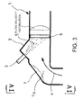
- Figs. 3 and 4 show a second embodiment of the invention in which a depression 7 is added on an outward portion of the bend 1a in the bending direction so as to suppress any flow of the exhaust gas 4 toward outward of the bending direction and rectify any biased flow velocity distribution.
- the depression 7 is formed which provides a concavely curved portion on the outward portion of the bend 1a in the bending direction.
- the depression 7 suppresses any flow of the exhaust gas 4 passing the bend 1a of the exhaust pipe 1 toward outward of the bending direction and guides the flow of the exhaust gas 4 toward centrally of the exhaust pipe 1, so that the tendency of the exhaust gas 4 flowing biasedly and in relatively much amount toward outward of the bending direction is remedied to rectify any biased flow distribution of the exhaust gas 4.
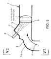
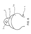
- Figs. 5 and 6 show a third embodiment of the invention in which the depression 7 providing the concavely curved portion in the previous second embodiment (see Figs. 3 and 4 ) is replaced by a depression 8 provided by crashing the outward portion of the bend 1a in the bending direction into wholly flattened oval.
- the depression 8 suppresses any flow of the exhaust gas 4 passing the bend 1a of the exhaust pipe 1 toward outward of the bend 1a of the exhaust pipe 1 and guides the flow of the exhaust gas 4 toward centrally of the exhaust pipe 1, so that the tendency of the exhaust gas 4 flowing biasedly and in relatively much amount toward outward of the bending direction is remedied to rectify any biased flow distribution of exhaust gas 4.
- Fig. 7 shows a fourth embodiment of the invention in which a baffle plate 9 is arranged in the bend 1a to suppress any flow of the exhaust gas 4 toward outward of the bending direction and rectify any biased flow velocity distribution.
- part of the flow of the exhaust gas 4 passing the bend 1a of the exhaust pipe 1 toward outward of the bending direction is forcedly guided by the baffle plate 9 toward centrally of the exhaust pipe 1, so that the tendency of the exhaust gas 4 flowing biasedly and in relatively much amount toward outward of the bending direction is remedied to rectify any biased flow distribution of the exhaust gas 4.
- any biased flow distribution of the exhaust gas 4 is remedied, which makes it further unlikely to form the urea water 5 along the inside wall of the exhaust pipe 1 due to the influence of the biased flow of the exhaust gas 4 and facilitates dispersion of the urea water 5 injected from the injector 3 into the exhaust gas 4, so that even if the injector 3 is arranged immediately after the bend 1a of the exhaust pipe 1, similarly to the previous first embodiment, the urea water 5 can be satisfactorily dispersed and can be uniformly sprayed to the mixer 6 to improve efficiency of conversion into ammonia while substantially suppressing adhesion of the urea water 5 not converted into ammonia and any substances produced in the course of the conversion onto the inside wall of the exhaust pipe 1 and resultant precipitation of substances derived from the urea water 5 and material corrosion due to highly corrosive intermediate products produced.
- a mixing structure according to the invention is not limited to the above embodiments and that various changes and modifications may be made without departing from the scope of the invention.
- the selective reduction catalyst arranged downstream of the injector may be directed in any direction and may be combined with any other particulate filter and the like.
Landscapes
- Engineering & Computer Science (AREA)
- Chemical & Material Sciences (AREA)
- Chemical Kinetics & Catalysis (AREA)
- Combustion & Propulsion (AREA)
- General Engineering & Computer Science (AREA)
- Mechanical Engineering (AREA)
- Health & Medical Sciences (AREA)
- Toxicology (AREA)
- General Chemical & Material Sciences (AREA)
- Oil, Petroleum & Natural Gas (AREA)
- Analytical Chemistry (AREA)
- Environmental & Geological Engineering (AREA)
- Biomedical Technology (AREA)
- Exhaust Gas After Treatment (AREA)
- Exhaust Silencers (AREA)
Abstract
Description
- The present invention relates to a mixing structure for mixing urea water, which is added as a reducing agent upstream of a selective reduction catalyst for reduction and depuration of NOx, with exhaust gas.
- Conventionally, some diesel engines have a selective reduction catalyst incorporated in an exhaust pipe for flow of exhaust gas, said catalyst having a property of selectively reacting NOx with a reducing agent even in the presence of oxygen. A required amount of reducing agent is added upstream of the selective reduction catalyst and is reacted on the catalyst with NOx (nitrogen oxides) in the exhaust gas to thereby reduce a concentration of NOx discharged.
- Effectiveness of ammonia (NH3) used as a reducing agent for reduction and depuration of NOx is well known in a field of a plant or the like with industrial flue gas denitration. However, in a field of automobile where safety is hard to assure as to running with ammonia itself being loaded, proposed is use of nontoxic urea water as a reducing agent.
- More specifically, the urea water, which is added into the exhaust gas upstream of the selective reduction catalyst, is hydrolyzed in the exhaust gas into ammonia and carbon dioxide gas according to a following equation to thereby satisfactorily reduce and depurate NOx in the exhaust gas with the ammonia on the catalyst.
[Equation 1] (NH2)2CO + H2O → 2NH3 + CO2
- Shown in
Fig. 1 is an example of conventional art for addition of urea water into exhaust gas upstream of a selective reduction catalyst. In the example illustrated, an outer periphery of anexhaust pipe 1 is formed with abulge portion 2 protruding obliquely upstream. Attached upstream of thebulge portion 2 is aninjector 3 directed obliquely downstream to approach an inside of theexhaust pipe 1 so as to addurea water 5 while theinjector 3 is protected from being directly exposed to the flow of thehot exhaust gas 4. - Arranged in the
exhaust pipe 1 immediately after thebulge portion 2 is amixer 6 constituted by thin grate plates with planar surfaces in a direction of the flow of theexhaust gas 4 such that theurea water 5, which is sprayed from theinjector 3 to themixer 6 having been exposed to and elevated in temperature by the flow of theexhaust gas 4, is atomized and heated for facilitated conversion into ammonia. - There is, for example, the following
Patent Literature 1 as conventional art document concerning this kind of mixing structure. - [Patent Literature 1]
JP 2010-203248A - However, in order to compactly lay out a relatively large-volume selective reduction catalyst in a limited configuration space while preventing interference with peripheral devices and structures, there may be a case where an
injector 3 has to be arranged immediately after thebend 1a of theexhaust pipe 1. In such case, there may occur a problem thatexhaust gas 4 passes thebend 1a in a biased manner toward outward of the bending direction and theurea water 5 is urged by influence of such biased flow of theexhaust gas 4 to form a flow along an inside wall of theexhaust pipe 1, failing in satisfactory dispersion of theurea water 5. Resultant failure in uniform spraying of theurea water 5 to themixer 6 may bring about lowered efficiency of conversion into ammonia as well as adhesion of theurea water 5 not converted into ammonia and any substances produced in a course of the conversion onto the inside wall of theexhaust pipe 1, leading to precipitation of substances derived from theurea water 5 and material corrosion due to highly corrosive intermediate products produced. - The above-mentioned biased flow of the
exhaust gas 4 may be rectified if ensured is adequate length of a distance L from thebend 1a of theexhaust pipe 1 to an added position of theurea water 5 from theinjector 3, which may, however, bring about a preposterous result that difficulty in compactly laying out the selective reduction catalyst leads to deteriorated mountability. - More specifically, in order to obtain enough reaction time of the
urea water 5, a distance from the added position of theurea water 5 from theinjector 3 to a downstream selective reduction catalyst must be lengthened to an extent possible; however, to take such step or countermeasure becomes difficult when lengthened is the distance L from thebend 1a of theexhaust pipe 1 to the added position of theurea water 5 from theinjector 3. - The invention was made in view of the above and has its object to provide a mixing structure capable of satisfactorily dispersing urea water even if an injector is arranged immediately after a bend of an exhaust pipe.
- The invention is directed to a mixing structure with an injector arranged immediately after a bend of an exhaust pipe, urea water being injected by said injector into said exhaust pipe for mixing, characterized in that a pipe diameter of the exhaust pipe downstream of said bend is large relative to a pipe diameter of the exhaust pipe upstream.
- Thus, in this manner, the exhaust gas flowing through the exhaust pipe with the relatively small pipe diameter passes the bend and enters into the exhaust pipe with the relatively large pipe diameter, which lowers a flow velocity, dulls influence of the biased flow toward outward of the bending direction in the bend of said exhaust pipe, makes it unlikely to form the flow of the urea water along an inside wall of the exhaust pipe due to influence of the biased flow of the exhaust gas, and facilitates dispersion of the urea water injected from the injector into the exhaust gas.
- Further, in the invention, an outward portion of the bend in the bending direction may be formed with a depression which suppresses any flow of the exhaust gas toward outward of the bending direction to remedy any biased flow velocity distribution. By this, said depression suppresses the flow of the exhaust gas passing the bend of the exhaust pipe toward outward of the bending direction, guides the flow of the exhaust gas toward centrally of the exhaust pipe, so that a tendency of the exhaust gas flowing biasedly and in relatively much amount toward outward of the bending direction is remedied to rectify any biased flow distribution of the exhaust gas.
- As a result, it becomes further unlikely to form the flow of the urea water along the inside wall of the exhaust pipe due to influence by the biased flow of the exhaust gas, thereby facilitating dispersion of the urea water injected by the injector into the exhaust gas.
- Alternatively, in the invention, a baffle plate may be arranged in the bend to suppress any flow of the exhaust gas toward outward of the bending direction to remedy any biased flow velocity distribution. By this, said baffle plate forces part of the flow of the exhaust gas passing the bend of the exhaust pipe, which is toward outward of the bending direction, to flow toward centrally of the exhaust pipe so that the tendency of the exhaust gas flowing biasedly and in relatively much amount toward outward of the bending direction is remedied to rectify any biased flow distribution of the exhaust gas.
- As a result, it becomes further unlikely to form the flow of the urea water along the inside wall of the exhaust pipe due to influence by the biased flow of the exhaust gas, thereby facilitating dispersion of the urea water injected by the injector into the exhaust gas.
- A mixing structure of the invention mentioned in the above has excellent effects that the urea water can be satisfactorily dispersed even if the injector is arranged immediately after the bend of the exhaust pipe to thereby improve efficiency of conversion of the urea water into ammonia while substantially suppressing adhesion of the urea water not converted into ammonia and any substances produced in the course of the conversion onto the inside wall of the exhaust pipe and resultant precipitation of substances derived from the urea water and material corrosion due to highly corrosive intermediate products produced.
-
-
Fig. 1 is a schematic view showing a conventional structure; -
Fig. 2 is a schematic view showing a first embodiment of the invention; -
Fig. 3 is a schematic view showing a second embodiment of the invention; -
Fig. 4 is a view looking in a direction of arrows IV inFig. 3 ; -
Fig. 5 is a schematic view showing a third embodiment of the invention; -
Fig. 6 is a view looking in a direction of arrows VI inFig. 5 ; and -
Fig. 7 is a schematic view showing a fourth embodiment of the invention. - Next, embodiments of the invention will be described in conjunction with the drawings.
-
Fig. 2 shows a first embodiment of the invention. In the embodiment illustrated, similarly to the above-mentioned conventional example shown inFig. 1 , an outer periphery of anexhaust pipe 1 immediately after thebend 1a thereof is formed with abulge portion 2 protruding obliquely upstream. Attached upstream of thebulge portion 2 is aninjector 3 directed obliquely downstream to approach an inside of theexhaust pipe 1 so as to addurea water 5 while theinjector 3 is protected from being directly exposed to the flow of thehot exhaust gas 4. Arranged in theexhaust pipe 1 immediately after thebulge portion 2 is amixer 6 constituted by thin grate plates with planar surfaces in a direction of the flow of theexhaust gas 4. A pipe diameter Dp of theexhaust pipe 1 downstream of thebend 1a is large relative to a pipe diameter De of theexhaust pipe 1 upstream. - Thus, in this manner, the
exhaust gas 4 flowing through theexhaust pipe 1 with relatively small pipe diameter passes thebend 1a and enters into theexhaust pipe 1 with relatively large pipe diameter, which lowers a flow velocity, dulls influence of biased flow toward outward of the bending direction in thebend 1a of theexhaust pipe 1, makes it unlikely to form the flow of theurea water 5 along the inside wall of theexhaust pipe 1 due to influence of the biased flow of theexhaust gas 4, and facilitates dispersion of theurea water 5 injected from theinjector 3 into theexhaust gas 4. - Thus, according to the above embodiment, even if the
injector 3 is arranged immediately after thebend 1a of theexhaust pipe 1, theurea water 5 can be satisfactorily dispersed and can be uniformly sprayed to themixer 6 to thereby improve efficiency of conversion into ammonia while substantially suppressing adhesion of theurea water 5 not converted into ammonia and any substances produced in the course of the conversion onto the inside wall of theexhaust pipe 1 and resultant precipitation of substances derived from theurea water 5 and material corrosion due to highly corrosive intermediate products produced. -
Figs. 3 and4 show a second embodiment of the invention in which adepression 7 is added on an outward portion of thebend 1a in the bending direction so as to suppress any flow of theexhaust gas 4 toward outward of the bending direction and rectify any biased flow velocity distribution. Especially inFig. 3 embodiment, thedepression 7 is formed which provides a concavely curved portion on the outward portion of thebend 1a in the bending direction. - In this manner, the
depression 7 suppresses any flow of theexhaust gas 4 passing thebend 1a of theexhaust pipe 1 toward outward of the bending direction and guides the flow of theexhaust gas 4 toward centrally of theexhaust pipe 1, so that the tendency of theexhaust gas 4 flowing biasedly and in relatively much amount toward outward of the bending direction is remedied to rectify any biased flow distribution of theexhaust gas 4. - Further,
Figs. 5 and6 show a third embodiment of the invention in which thedepression 7 providing the concavely curved portion in the previous second embodiment (seeFigs. 3 and4 ) is replaced by adepression 8 provided by crashing the outward portion of thebend 1a in the bending direction into wholly flattened oval. Also in this case, thedepression 8 suppresses any flow of theexhaust gas 4 passing thebend 1a of theexhaust pipe 1 toward outward of thebend 1a of theexhaust pipe 1 and guides the flow of theexhaust gas 4 toward centrally of theexhaust pipe 1, so that the tendency of theexhaust gas 4 flowing biasedly and in relatively much amount toward outward of the bending direction is remedied to rectify any biased flow distribution ofexhaust gas 4. -
Fig. 7 shows a fourth embodiment of the invention in which abaffle plate 9 is arranged in thebend 1a to suppress any flow of theexhaust gas 4 toward outward of the bending direction and rectify any biased flow velocity distribution. - In this case, part of the flow of the
exhaust gas 4 passing thebend 1a of theexhaust pipe 1 toward outward of the bending direction is forcedly guided by thebaffle plate 9 toward centrally of theexhaust pipe 1, so that the tendency of theexhaust gas 4 flowing biasedly and in relatively much amount toward outward of the bending direction is remedied to rectify any biased flow distribution of theexhaust gas 4. - As mentioned in the above, in any of the second to fourth embodiments, any biased flow distribution of the
exhaust gas 4 is remedied, which makes it further unlikely to form theurea water 5 along the inside wall of theexhaust pipe 1 due to the influence of the biased flow of theexhaust gas 4 and facilitates dispersion of theurea water 5 injected from theinjector 3 into theexhaust gas 4, so that even if theinjector 3 is arranged immediately after thebend 1a of theexhaust pipe 1, similarly to the previous first embodiment, theurea water 5 can be satisfactorily dispersed and can be uniformly sprayed to themixer 6 to improve efficiency of conversion into ammonia while substantially suppressing adhesion of theurea water 5 not converted into ammonia and any substances produced in the course of the conversion onto the inside wall of theexhaust pipe 1 and resultant precipitation of substances derived from theurea water 5 and material corrosion due to highly corrosive intermediate products produced. - It is to be understood that a mixing structure according to the invention is not limited to the above embodiments and that various changes and modifications may be made without departing from the scope of the invention. For example, the selective reduction catalyst arranged downstream of the injector may be directed in any direction and may be combined with any other particulate filter and the like.
-
- 1
- exhaust pipe
- 1a
- bend
- 3
- injector
- 4
- exhaust gas
- 5
- urea water
- 7
- depression
- 8
- depression
- 9
- baffle plate
- De
- pipe diameter
- Dp
- pipe diameter
Claims (3)
- A mixing structure with an injector arranged immediately after a bend of an exhaust pipe, urea water being injected by said injector into said exhaust pipe for mixing, wherein a pipe diameter of the exhaust pipe downstream of said bend is large relative to a pipe diameter of the exhaust pipe upstream.
- The mixing structure as claimed in claim 1 wherein an outward portion of the bend in a bending direction is formed with a depression which suppresses any flow of the exhaust gas toward outward of the bending direction to remedy any biased flow velocity distribution.
- The mixing structure as claimed in claim 1 wherein a baffle plate is arranged in the bend to suppress any flow of the exhaust gas toward outward of the bending direction to remedy any biased flow velocity distribution.
Applications Claiming Priority (2)
| Application Number | Priority Date | Filing Date | Title |
|---|---|---|---|
| JP2012090978A JP5990025B2 (en) | 2012-04-12 | 2012-04-12 | Mixing structure |
| PCT/JP2013/002389 WO2013153797A1 (en) | 2012-04-12 | 2013-04-08 | Mixing structure |
Publications (3)
| Publication Number | Publication Date |
|---|---|
| EP2857644A1 true EP2857644A1 (en) | 2015-04-08 |
| EP2857644A4 EP2857644A4 (en) | 2016-03-02 |
| EP2857644B1 EP2857644B1 (en) | 2018-05-30 |
Family
ID=49327382
Family Applications (1)
| Application Number | Title | Priority Date | Filing Date |
|---|---|---|---|
| EP13775517.9A Not-in-force EP2857644B1 (en) | 2012-04-12 | 2013-04-08 | Mixing structure |
Country Status (5)
| Country | Link |
|---|---|
| US (1) | US9649595B2 (en) |
| EP (1) | EP2857644B1 (en) |
| JP (1) | JP5990025B2 (en) |
| CN (1) | CN104321505A (en) |
| WO (1) | WO2013153797A1 (en) |
Families Citing this family (5)
| Publication number | Priority date | Publication date | Assignee | Title |
|---|---|---|---|---|
| JP6282931B2 (en) | 2014-05-20 | 2018-02-21 | 日野自動車株式会社 | Mixing structure |
| GB2539114A (en) * | 2016-07-05 | 2016-12-07 | Daimler Ag | Mixing device and aftertreatment device |
| KR101846906B1 (en) * | 2016-09-02 | 2018-04-09 | 현대자동차 주식회사 | Exhaust gas purification system |
| DE102017100132A1 (en) * | 2017-01-05 | 2018-07-05 | Eberspächer Exhaust Technology GmbH & Co. KG | exhaust system |
| JP7080679B2 (en) * | 2018-03-14 | 2022-06-06 | 株式会社豊田自動織機 | Internal combustion engine additive dispersion system |
Family Cites Families (18)
| Publication number | Priority date | Publication date | Assignee | Title |
|---|---|---|---|---|
| JP4524970B2 (en) * | 2001-08-02 | 2010-08-18 | マツダ株式会社 | Engine exhaust system structure |
| JP2005214100A (en) * | 2004-01-30 | 2005-08-11 | Hino Motors Ltd | Exhaust purification equipment |
| JP2006017018A (en) | 2004-06-30 | 2006-01-19 | Toyota Motor Corp | Structure of exhaust pipe for vehicles |
| US8230674B2 (en) * | 2004-12-23 | 2012-07-31 | Umicore Ag & Co. Kg | Method for monitoring the nitrogen oxide storage capacity of a nitrogen oxide storage catalyst used in the form of a primary catalytic converter |
| JP3686672B1 (en) * | 2004-12-24 | 2005-08-24 | 日産ディーゼル工業株式会社 | Engine exhaust purification system |
| JP2006329019A (en) * | 2005-05-25 | 2006-12-07 | Hino Motors Ltd | Diesel engine exhaust pipe |
| JP2008151039A (en) * | 2006-12-18 | 2008-07-03 | Mitsubishi Motors Corp | Exhaust purification device |
| JP4893454B2 (en) * | 2007-04-27 | 2012-03-07 | トヨタ自動車株式会社 | Dispersion plate |
| JP4920532B2 (en) | 2007-09-13 | 2012-04-18 | 日野自動車株式会社 | Exhaust purification device |
| JP2009156071A (en) * | 2007-12-25 | 2009-07-16 | Mitsubishi Motors Corp | Exhaust gas purification device for internal combustion engine |
| JP4332755B2 (en) * | 2007-12-25 | 2009-09-16 | 三菱自動車工業株式会社 | Exhaust gas purification device for internal combustion engine |
| JP4332756B2 (en) * | 2007-12-25 | 2009-09-16 | 三菱自動車工業株式会社 | Exhaust gas purification device for internal combustion engine |
| JP5141900B2 (en) * | 2008-07-30 | 2013-02-13 | 三菱自動車工業株式会社 | Exhaust purification device |
| JP4826639B2 (en) * | 2009-02-27 | 2011-11-30 | トヨタ自動車株式会社 | Exhaust pipe structure of internal combustion engine |
| JP2010248955A (en) * | 2009-04-14 | 2010-11-04 | Hino Motors Ltd | Exhaust purification device |
| US20110079003A1 (en) * | 2009-10-05 | 2011-04-07 | Caterpillar Inc. | Reductant nozzle indentation mount |
| JP5714844B2 (en) * | 2010-07-16 | 2015-05-07 | いすゞ自動車株式会社 | Exhaust gas purification device |
| SE535198C2 (en) * | 2010-09-30 | 2012-05-15 | Scania Cv Ab | Arrangement for introducing a liquid medium into exhaust gases from an internal combustion engine |
-
2012
- 2012-04-12 JP JP2012090978A patent/JP5990025B2/en active Active
-
2013
- 2013-04-08 EP EP13775517.9A patent/EP2857644B1/en not_active Not-in-force
- 2013-04-08 WO PCT/JP2013/002389 patent/WO2013153797A1/en not_active Ceased
- 2013-04-08 CN CN201380019459.XA patent/CN104321505A/en active Pending
- 2013-04-08 US US14/376,750 patent/US9649595B2/en not_active Expired - Fee Related
Also Published As
| Publication number | Publication date |
|---|---|
| CN104321505A (en) | 2015-01-28 |
| JP5990025B2 (en) | 2016-09-07 |
| JP2013217350A (en) | 2013-10-24 |
| EP2857644B1 (en) | 2018-05-30 |
| WO2013153797A1 (en) | 2013-10-17 |
| EP2857644A4 (en) | 2016-03-02 |
| US20150041996A1 (en) | 2015-02-12 |
| US9649595B2 (en) | 2017-05-16 |
Similar Documents
| Publication | Publication Date | Title |
|---|---|---|
| US7908845B2 (en) | Mixing apparatus for an exhaust after-treatment system | |
| EP2857644B1 (en) | Mixing structure | |
| US8813481B2 (en) | Exhaust emission control device | |
| EP2098697B1 (en) | Exhaust system of an internal combustion engine | |
| EP2339139B1 (en) | Method for dosing an urea based reducing agent into a gas exhaust stream | |
| EP1712753B1 (en) | Module and method for introducing a urea solution into the exhaust gas of an engine | |
| WO2012008570A1 (en) | Exhaust gas purification device | |
| CN104136727A (en) | Exhaust gas purification device | |
| EP2339137B1 (en) | Dosing module for dosing an urea based reducing agent into an exhaust gas stream | |
| EP2549069B1 (en) | Exhaust gas purification device | |
| EP3168440B1 (en) | Mixing structure | |
| JP2008208761A (en) | Mixing structure | |
| EP3489480A1 (en) | Scr mixer and scr device comprising same | |
| CN107206315A (en) | Low temperature urea SCR operation in the presence of high-sulfur flue gas | |
| US10626771B2 (en) | Mixing structure | |
| Adelman et al. | Direct Injection into the Exhaust Stream of Gaseous Ammonia: Design and Efficiency of Injection and Mixing Hardware | |
| CN209818149U (en) | Reductant decomposition system | |
| CN105056756A (en) | Selective catalytic reduction (SCR) denitration stream turbulence device | |
| WO2018180457A1 (en) | Reactor | |
| JP2017106425A (en) | Exhaust purification device |
Legal Events
| Date | Code | Title | Description |
|---|---|---|---|
| PUAI | Public reference made under article 153(3) epc to a published international application that has entered the european phase |
Free format text: ORIGINAL CODE: 0009012 |
|
| 17P | Request for examination filed |
Effective date: 20141106 |
|
| AK | Designated contracting states |
Kind code of ref document: A1 Designated state(s): AL AT BE BG CH CY CZ DE DK EE ES FI FR GB GR HR HU IE IS IT LI LT LU LV MC MK MT NL NO PL PT RO RS SE SI SK SM TR |
|
| AX | Request for extension of the european patent |
Extension state: BA ME |
|
| DAX | Request for extension of the european patent (deleted) | ||
| REG | Reference to a national code |
Ref country code: DE Ref legal event code: R079 Ref document number: 602013038242 Country of ref document: DE Free format text: PREVIOUS MAIN CLASS: F01N0003080000 Ipc: F01N0003200000 |
|
| RA4 | Supplementary search report drawn up and despatched (corrected) |
Effective date: 20160203 |
|
| RIC1 | Information provided on ipc code assigned before grant |
Ipc: F01N 3/20 20060101AFI20160128BHEP Ipc: F01N 3/28 20060101ALI20160128BHEP |
|
| STAA | Information on the status of an ep patent application or granted ep patent |
Free format text: STATUS: EXAMINATION IS IN PROGRESS |
|
| 17Q | First examination report despatched |
Effective date: 20170418 |
|
| GRAP | Despatch of communication of intention to grant a patent |
Free format text: ORIGINAL CODE: EPIDOSNIGR1 |
|
| STAA | Information on the status of an ep patent application or granted ep patent |
Free format text: STATUS: GRANT OF PATENT IS INTENDED |
|
| INTG | Intention to grant announced |
Effective date: 20171201 |
|
| GRAS | Grant fee paid |
Free format text: ORIGINAL CODE: EPIDOSNIGR3 |
|
| GRAA | (expected) grant |
Free format text: ORIGINAL CODE: 0009210 |
|
| STAA | Information on the status of an ep patent application or granted ep patent |
Free format text: STATUS: THE PATENT HAS BEEN GRANTED |
|
| AK | Designated contracting states |
Kind code of ref document: B1 Designated state(s): AL AT BE BG CH CY CZ DE DK EE ES FI FR GB GR HR HU IE IS IT LI LT LU LV MC MK MT NL NO PL PT RO RS SE SI SK SM TR |
|
| REG | Reference to a national code |
Ref country code: GB Ref legal event code: FG4D |
|
| REG | Reference to a national code |
Ref country code: CH Ref legal event code: EP |
|
| REG | Reference to a national code |
Ref country code: AT Ref legal event code: REF Ref document number: 1003816 Country of ref document: AT Kind code of ref document: T Effective date: 20180615 |
|
| REG | Reference to a national code |
Ref country code: IE Ref legal event code: FG4D |
|
| REG | Reference to a national code |
Ref country code: DE Ref legal event code: R096 Ref document number: 602013038242 Country of ref document: DE |
|
| REG | Reference to a national code |
Ref country code: NL Ref legal event code: MP Effective date: 20180530 |
|
| REG | Reference to a national code |
Ref country code: LT Ref legal event code: MG4D |
|
| PG25 | Lapsed in a contracting state [announced via postgrant information from national office to epo] |
Ref country code: SE Free format text: LAPSE BECAUSE OF FAILURE TO SUBMIT A TRANSLATION OF THE DESCRIPTION OR TO PAY THE FEE WITHIN THE PRESCRIBED TIME-LIMIT Effective date: 20180530 Ref country code: BG Free format text: LAPSE BECAUSE OF FAILURE TO SUBMIT A TRANSLATION OF THE DESCRIPTION OR TO PAY THE FEE WITHIN THE PRESCRIBED TIME-LIMIT Effective date: 20180830 Ref country code: FI Free format text: LAPSE BECAUSE OF FAILURE TO SUBMIT A TRANSLATION OF THE DESCRIPTION OR TO PAY THE FEE WITHIN THE PRESCRIBED TIME-LIMIT Effective date: 20180530 Ref country code: NO Free format text: LAPSE BECAUSE OF FAILURE TO SUBMIT A TRANSLATION OF THE DESCRIPTION OR TO PAY THE FEE WITHIN THE PRESCRIBED TIME-LIMIT Effective date: 20180830 Ref country code: CY Free format text: LAPSE BECAUSE OF FAILURE TO SUBMIT A TRANSLATION OF THE DESCRIPTION OR TO PAY THE FEE WITHIN THE PRESCRIBED TIME-LIMIT Effective date: 20180530 Ref country code: ES Free format text: LAPSE BECAUSE OF FAILURE TO SUBMIT A TRANSLATION OF THE DESCRIPTION OR TO PAY THE FEE WITHIN THE PRESCRIBED TIME-LIMIT Effective date: 20180530 Ref country code: LT Free format text: LAPSE BECAUSE OF FAILURE TO SUBMIT A TRANSLATION OF THE DESCRIPTION OR TO PAY THE FEE WITHIN THE PRESCRIBED TIME-LIMIT Effective date: 20180530 |
|
| PG25 | Lapsed in a contracting state [announced via postgrant information from national office to epo] |
Ref country code: GR Free format text: LAPSE BECAUSE OF FAILURE TO SUBMIT A TRANSLATION OF THE DESCRIPTION OR TO PAY THE FEE WITHIN THE PRESCRIBED TIME-LIMIT Effective date: 20180831 Ref country code: HR Free format text: LAPSE BECAUSE OF FAILURE TO SUBMIT A TRANSLATION OF THE DESCRIPTION OR TO PAY THE FEE WITHIN THE PRESCRIBED TIME-LIMIT Effective date: 20180530 Ref country code: LV Free format text: LAPSE BECAUSE OF FAILURE TO SUBMIT A TRANSLATION OF THE DESCRIPTION OR TO PAY THE FEE WITHIN THE PRESCRIBED TIME-LIMIT Effective date: 20180530 Ref country code: RS Free format text: LAPSE BECAUSE OF FAILURE TO SUBMIT A TRANSLATION OF THE DESCRIPTION OR TO PAY THE FEE WITHIN THE PRESCRIBED TIME-LIMIT Effective date: 20180530 |
|
| REG | Reference to a national code |
Ref country code: AT Ref legal event code: MK05 Ref document number: 1003816 Country of ref document: AT Kind code of ref document: T Effective date: 20180530 |
|
| PG25 | Lapsed in a contracting state [announced via postgrant information from national office to epo] |
Ref country code: NL Free format text: LAPSE BECAUSE OF FAILURE TO SUBMIT A TRANSLATION OF THE DESCRIPTION OR TO PAY THE FEE WITHIN THE PRESCRIBED TIME-LIMIT Effective date: 20180530 |
|
| PG25 | Lapsed in a contracting state [announced via postgrant information from national office to epo] |
Ref country code: CZ Free format text: LAPSE BECAUSE OF FAILURE TO SUBMIT A TRANSLATION OF THE DESCRIPTION OR TO PAY THE FEE WITHIN THE PRESCRIBED TIME-LIMIT Effective date: 20180530 Ref country code: RO Free format text: LAPSE BECAUSE OF FAILURE TO SUBMIT A TRANSLATION OF THE DESCRIPTION OR TO PAY THE FEE WITHIN THE PRESCRIBED TIME-LIMIT Effective date: 20180530 Ref country code: AT Free format text: LAPSE BECAUSE OF FAILURE TO SUBMIT A TRANSLATION OF THE DESCRIPTION OR TO PAY THE FEE WITHIN THE PRESCRIBED TIME-LIMIT Effective date: 20180530 Ref country code: PL Free format text: LAPSE BECAUSE OF FAILURE TO SUBMIT A TRANSLATION OF THE DESCRIPTION OR TO PAY THE FEE WITHIN THE PRESCRIBED TIME-LIMIT Effective date: 20180530 Ref country code: EE Free format text: LAPSE BECAUSE OF FAILURE TO SUBMIT A TRANSLATION OF THE DESCRIPTION OR TO PAY THE FEE WITHIN THE PRESCRIBED TIME-LIMIT Effective date: 20180530 Ref country code: DK Free format text: LAPSE BECAUSE OF FAILURE TO SUBMIT A TRANSLATION OF THE DESCRIPTION OR TO PAY THE FEE WITHIN THE PRESCRIBED TIME-LIMIT Effective date: 20180530 Ref country code: SK Free format text: LAPSE BECAUSE OF FAILURE TO SUBMIT A TRANSLATION OF THE DESCRIPTION OR TO PAY THE FEE WITHIN THE PRESCRIBED TIME-LIMIT Effective date: 20180530 |
|
| PG25 | Lapsed in a contracting state [announced via postgrant information from national office to epo] |
Ref country code: IT Free format text: LAPSE BECAUSE OF FAILURE TO SUBMIT A TRANSLATION OF THE DESCRIPTION OR TO PAY THE FEE WITHIN THE PRESCRIBED TIME-LIMIT Effective date: 20180530 Ref country code: SM Free format text: LAPSE BECAUSE OF FAILURE TO SUBMIT A TRANSLATION OF THE DESCRIPTION OR TO PAY THE FEE WITHIN THE PRESCRIBED TIME-LIMIT Effective date: 20180530 |
|
| REG | Reference to a national code |
Ref country code: DE Ref legal event code: R097 Ref document number: 602013038242 Country of ref document: DE |
|
| PLBE | No opposition filed within time limit |
Free format text: ORIGINAL CODE: 0009261 |
|
| STAA | Information on the status of an ep patent application or granted ep patent |
Free format text: STATUS: NO OPPOSITION FILED WITHIN TIME LIMIT |
|
| PGFP | Annual fee paid to national office [announced via postgrant information from national office to epo] |
Ref country code: GB Payment date: 20190327 Year of fee payment: 7 |
|
| 26N | No opposition filed |
Effective date: 20190301 |
|
| PG25 | Lapsed in a contracting state [announced via postgrant information from national office to epo] |
Ref country code: SI Free format text: LAPSE BECAUSE OF FAILURE TO SUBMIT A TRANSLATION OF THE DESCRIPTION OR TO PAY THE FEE WITHIN THE PRESCRIBED TIME-LIMIT Effective date: 20180530 |
|
| PGFP | Annual fee paid to national office [announced via postgrant information from national office to epo] |
Ref country code: DE Payment date: 20190328 Year of fee payment: 7 |
|
| PG25 | Lapsed in a contracting state [announced via postgrant information from national office to epo] |
Ref country code: AL Free format text: LAPSE BECAUSE OF FAILURE TO SUBMIT A TRANSLATION OF THE DESCRIPTION OR TO PAY THE FEE WITHIN THE PRESCRIBED TIME-LIMIT Effective date: 20180530 |
|
| REG | Reference to a national code |
Ref country code: CH Ref legal event code: PL |
|
| REG | Reference to a national code |
Ref country code: BE Ref legal event code: MM Effective date: 20190430 |
|
| PG25 | Lapsed in a contracting state [announced via postgrant information from national office to epo] |
Ref country code: MC Free format text: LAPSE BECAUSE OF FAILURE TO SUBMIT A TRANSLATION OF THE DESCRIPTION OR TO PAY THE FEE WITHIN THE PRESCRIBED TIME-LIMIT Effective date: 20180530 Ref country code: LU Free format text: LAPSE BECAUSE OF NON-PAYMENT OF DUE FEES Effective date: 20190408 |
|
| PG25 | Lapsed in a contracting state [announced via postgrant information from national office to epo] |
Ref country code: LI Free format text: LAPSE BECAUSE OF NON-PAYMENT OF DUE FEES Effective date: 20190430 Ref country code: CH Free format text: LAPSE BECAUSE OF NON-PAYMENT OF DUE FEES Effective date: 20190430 |
|
| PG25 | Lapsed in a contracting state [announced via postgrant information from national office to epo] |
Ref country code: BE Free format text: LAPSE BECAUSE OF NON-PAYMENT OF DUE FEES Effective date: 20190430 Ref country code: FR Free format text: LAPSE BECAUSE OF NON-PAYMENT OF DUE FEES Effective date: 20190430 |
|
| PG25 | Lapsed in a contracting state [announced via postgrant information from national office to epo] |
Ref country code: TR Free format text: LAPSE BECAUSE OF FAILURE TO SUBMIT A TRANSLATION OF THE DESCRIPTION OR TO PAY THE FEE WITHIN THE PRESCRIBED TIME-LIMIT Effective date: 20180530 |
|
| PG25 | Lapsed in a contracting state [announced via postgrant information from national office to epo] |
Ref country code: IE Free format text: LAPSE BECAUSE OF NON-PAYMENT OF DUE FEES Effective date: 20190408 |
|
| PG25 | Lapsed in a contracting state [announced via postgrant information from national office to epo] |
Ref country code: PT Free format text: LAPSE BECAUSE OF FAILURE TO SUBMIT A TRANSLATION OF THE DESCRIPTION OR TO PAY THE FEE WITHIN THE PRESCRIBED TIME-LIMIT Effective date: 20181001 |
|
| REG | Reference to a national code |
Ref country code: DE Ref legal event code: R119 Ref document number: 602013038242 Country of ref document: DE |
|
| PG25 | Lapsed in a contracting state [announced via postgrant information from national office to epo] |
Ref country code: DE Free format text: LAPSE BECAUSE OF NON-PAYMENT OF DUE FEES Effective date: 20201103 |
|
| GBPC | Gb: european patent ceased through non-payment of renewal fee |
Effective date: 20200408 |
|
| PG25 | Lapsed in a contracting state [announced via postgrant information from national office to epo] |
Ref country code: GB Free format text: LAPSE BECAUSE OF NON-PAYMENT OF DUE FEES Effective date: 20200408 |
|
| PG25 | Lapsed in a contracting state [announced via postgrant information from national office to epo] |
Ref country code: IS Free format text: LAPSE BECAUSE OF FAILURE TO SUBMIT A TRANSLATION OF THE DESCRIPTION OR TO PAY THE FEE WITHIN THE PRESCRIBED TIME-LIMIT Effective date: 20180930 |
|
| PG25 | Lapsed in a contracting state [announced via postgrant information from national office to epo] |
Ref country code: HU Free format text: LAPSE BECAUSE OF FAILURE TO SUBMIT A TRANSLATION OF THE DESCRIPTION OR TO PAY THE FEE WITHIN THE PRESCRIBED TIME-LIMIT; INVALID AB INITIO Effective date: 20130408 Ref country code: MT Free format text: LAPSE BECAUSE OF FAILURE TO SUBMIT A TRANSLATION OF THE DESCRIPTION OR TO PAY THE FEE WITHIN THE PRESCRIBED TIME-LIMIT Effective date: 20180530 |
|
| PG25 | Lapsed in a contracting state [announced via postgrant information from national office to epo] |
Ref country code: MK Free format text: LAPSE BECAUSE OF FAILURE TO SUBMIT A TRANSLATION OF THE DESCRIPTION OR TO PAY THE FEE WITHIN THE PRESCRIBED TIME-LIMIT Effective date: 20180530 |