EP2857296A1 - Vehicle body assembling method and vehicle body assembling device - Google Patents
Vehicle body assembling method and vehicle body assembling device Download PDFInfo
- Publication number
- EP2857296A1 EP2857296A1 EP20130800018 EP13800018A EP2857296A1 EP 2857296 A1 EP2857296 A1 EP 2857296A1 EP 20130800018 EP20130800018 EP 20130800018 EP 13800018 A EP13800018 A EP 13800018A EP 2857296 A1 EP2857296 A1 EP 2857296A1
- Authority
- EP
- European Patent Office
- Prior art keywords
- jig
- welding
- holding
- roof arch
- vehicle body
- Prior art date
- Legal status (The legal status is an assumption and is not a legal conclusion. Google has not performed a legal analysis and makes no representation as to the accuracy of the status listed.)
- Granted
Links
Images



Classifications
-
- B—PERFORMING OPERATIONS; TRANSPORTING
- B62—LAND VEHICLES FOR TRAVELLING OTHERWISE THAN ON RAILS
- B62D—MOTOR VEHICLES; TRAILERS
- B62D65/00—Designing, manufacturing, e.g. assembling, facilitating disassembly, or structurally modifying motor vehicles or trailers, not otherwise provided for
- B62D65/02—Joining sub-units or components to, or positioning sub-units or components with respect to, body shell or other sub-units or components
- B62D65/024—Positioning of sub-units or components with respect to body shell or other sub-units or components
- B62D65/026—Positioning of sub-units or components with respect to body shell or other sub-units or components by using a jig or the like; Positioning of the jig
-
- B—PERFORMING OPERATIONS; TRANSPORTING
- B23—MACHINE TOOLS; METAL-WORKING NOT OTHERWISE PROVIDED FOR
- B23K—SOLDERING OR UNSOLDERING; WELDING; CLADDING OR PLATING BY SOLDERING OR WELDING; CUTTING BY APPLYING HEAT LOCALLY, e.g. FLAME CUTTING; WORKING BY LASER BEAM
- B23K31/00—Processes relevant to this subclass, specially adapted for particular articles or purposes, but not covered by any single one of main groups B23K1/00 - B23K28/00
- B23K31/02—Processes relevant to this subclass, specially adapted for particular articles or purposes, but not covered by any single one of main groups B23K1/00 - B23K28/00 relating to soldering or welding
-
- B—PERFORMING OPERATIONS; TRANSPORTING
- B23—MACHINE TOOLS; METAL-WORKING NOT OTHERWISE PROVIDED FOR
- B23K—SOLDERING OR UNSOLDERING; WELDING; CLADDING OR PLATING BY SOLDERING OR WELDING; CUTTING BY APPLYING HEAT LOCALLY, e.g. FLAME CUTTING; WORKING BY LASER BEAM
- B23K37/00—Auxiliary devices or processes, not specially adapted for a procedure covered by only one of the other main groups of this subclass
- B23K37/04—Auxiliary devices or processes, not specially adapted for a procedure covered by only one of the other main groups of this subclass for holding or positioning work
- B23K37/0426—Fixtures for other work
-
- B—PERFORMING OPERATIONS; TRANSPORTING
- B23—MACHINE TOOLS; METAL-WORKING NOT OTHERWISE PROVIDED FOR
- B23K—SOLDERING OR UNSOLDERING; WELDING; CLADDING OR PLATING BY SOLDERING OR WELDING; CUTTING BY APPLYING HEAT LOCALLY, e.g. FLAME CUTTING; WORKING BY LASER BEAM
- B23K37/00—Auxiliary devices or processes, not specially adapted for a procedure covered by only one of the other main groups of this subclass
- B23K37/04—Auxiliary devices or processes, not specially adapted for a procedure covered by only one of the other main groups of this subclass for holding or positioning work
- B23K37/0426—Fixtures for other work
- B23K37/0435—Clamps
- B23K37/0443—Jigs
-
- B—PERFORMING OPERATIONS; TRANSPORTING
- B23—MACHINE TOOLS; METAL-WORKING NOT OTHERWISE PROVIDED FOR
- B23K—SOLDERING OR UNSOLDERING; WELDING; CLADDING OR PLATING BY SOLDERING OR WELDING; CUTTING BY APPLYING HEAT LOCALLY, e.g. FLAME CUTTING; WORKING BY LASER BEAM
- B23K37/00—Auxiliary devices or processes, not specially adapted for a procedure covered by only one of the other main groups of this subclass
- B23K37/04—Auxiliary devices or processes, not specially adapted for a procedure covered by only one of the other main groups of this subclass for holding or positioning work
- B23K37/047—Auxiliary devices or processes, not specially adapted for a procedure covered by only one of the other main groups of this subclass for holding or positioning work moving work to adjust its position between soldering, welding or cutting steps
-
- B—PERFORMING OPERATIONS; TRANSPORTING
- B23—MACHINE TOOLS; METAL-WORKING NOT OTHERWISE PROVIDED FOR
- B23K—SOLDERING OR UNSOLDERING; WELDING; CLADDING OR PLATING BY SOLDERING OR WELDING; CUTTING BY APPLYING HEAT LOCALLY, e.g. FLAME CUTTING; WORKING BY LASER BEAM
- B23K2101/00—Articles made by soldering, welding or cutting
- B23K2101/006—Vehicles
-
- B—PERFORMING OPERATIONS; TRANSPORTING
- B23—MACHINE TOOLS; METAL-WORKING NOT OTHERWISE PROVIDED FOR
- B23K—SOLDERING OR UNSOLDERING; WELDING; CLADDING OR PLATING BY SOLDERING OR WELDING; CUTTING BY APPLYING HEAT LOCALLY, e.g. FLAME CUTTING; WORKING BY LASER BEAM
- B23K2101/00—Articles made by soldering, welding or cutting
- B23K2101/18—Sheet panels
- B23K2101/185—Tailored blanks
-
- B—PERFORMING OPERATIONS; TRANSPORTING
- B23—MACHINE TOOLS; METAL-WORKING NOT OTHERWISE PROVIDED FOR
- B23K—SOLDERING OR UNSOLDERING; WELDING; CLADDING OR PLATING BY SOLDERING OR WELDING; CUTTING BY APPLYING HEAT LOCALLY, e.g. FLAME CUTTING; WORKING BY LASER BEAM
- B23K2103/00—Materials to be soldered, welded or cut
- B23K2103/08—Non-ferrous metals or alloys
- B23K2103/10—Aluminium or alloys thereof
-
- B—PERFORMING OPERATIONS; TRANSPORTING
- B23—MACHINE TOOLS; METAL-WORKING NOT OTHERWISE PROVIDED FOR
- B23K—SOLDERING OR UNSOLDERING; WELDING; CLADDING OR PLATING BY SOLDERING OR WELDING; CUTTING BY APPLYING HEAT LOCALLY, e.g. FLAME CUTTING; WORKING BY LASER BEAM
- B23K2103/00—Materials to be soldered, welded or cut
- B23K2103/18—Dissimilar materials
- B23K2103/20—Ferrous alloys and aluminium or alloys thereof
Definitions
- the present invention relates to a vehicle body assembling method and a vehicle body assembling device that form an inner frame of a vehicle body by using a floor assembly, side inner assemblies, and a roof arch.
- Patent Document 1 As a vehicle body assembling method for assembling a vehicle body by using a floor member, side members, and a roof member, there has been known a method in which jigs holding each of the members are connected to preliminarily assemble the members, and the preliminarily assembled members are welded (e.g. Patent Document 1).
- the floor jig, the side jig, and the roofjig are connected to preliminarily assemble the floor member, the side members, and the roof members. Then, while retaining the preliminarily assembled state, the jigs are carried as one piece to a plurality of stations at which the floor member, the side members, and the roof member are welded for preliminary assembling.
- the jigs are disconnected and separated to be detached. Then, additional welding is carried out to complete a main body.
- Patent Document 1 Japanese Patent Application Laid-open No. 2001-334973
- the conventional vehicle body assembling method described above requires carrying equipment for carrying the jigs in one piece and a number of welding machines for tack welding and additional welding at stations of a destination to which they are carried.
- various types of equipment have to be additionally provided.
- the vehicle body assembling method requires to secure cost and installation places for the additionally provided equipment.
- an object of the present invention is to provide space-saving, economical vehicle body assembling method and device.
- a vehicle body assembling method in accordance with the present invention is a vehicle body assembling method for forming an inner frame of a vehicle body by using a floor assembly, side inner assemblies, and a roof arch, comprising: a first holding step for holding the floor assembly by a first jig in a state in which the floor assembly is positioned at a predetermined holding position; a second holding step for holding the roof arch by a second jig in a state in which the roof arch is positioned at a predetermined holding position; a jig connecting step for connecting the first jig and the second jig so as to mutually position the floor assembly and the roof arch after the first holding step and the second holding step; a third holding step for holding the side inner assemblies by the first jig and the second jig in a state, in which the side inner assemblies are positioned with respect to the floor assembly and the roof arch, after the jig connecting step; and a welding step for connecting the floor assembly, the roof arch, and the side inner assemblies
- the inner frame is formed by welding the floor assembly, the side inner assemblies, and the roof arch while holding these components, which have been positioned by the first jig and the second jig, which are connected. This obviates the conventional need for carrying the jigs in one piece, while holding the each of the assemblies in an assembled state, to a plurality of processing stations or for tack welding or additional welding at each processing station.
- the inner frame can be formed from the floor assembly, the side inner assemblies, and the roof arch at a single processing station. Unlike the prior art, a number of equipment is not required, thus making it possible to provide a space-saving, economical vehicle body assembling method.
- the welding step may further comprise a first welding step for carrying out welding at some of all welding positions, a second jig retraction step for clearing the retainment of the roof arch and the side inner assemblies by the second jig and for retracting the second jig to a predetermined position after the first welding step, and a second welding step for carrying out the welding at remaining welding positions after the second jig retraction step.
- the welding is carried out at some welding positions, at which the existence of the second jig does not interfere with the welding, to preliminarily connect the floor assembly, the roof arch, and the side inner assemblies, and then the second jig is retracted to carry out the welding at the remaining welding positions, at which the existence of the second jig interferes with welding, thereby completely connecting the floor assembly, the roof arch, and the side inner assemblies.
- a part of the connection between the first jig and the second jig may be cleared before the second welding step. This makes it possible to carry out the welding also at the welding positions, at which the part of the connection interferes with the welding, in the second welding step.
- a vehicle body assembling device in accordance with the present invention is a vehicle body assembly device that forms an inner frame of a vehicle body by using a floor assembly, side inner assemblies, and a roof arch, comprising: a welding unit; a first jig that holds the floor assembly in a state in which the floor assembly is positioned at a predetermined holding position; a second jig that holds the roof arch in a state in which the roof arch is positioned at a predetermined holding position; and a connecting unit that mutually positions the floor assembly and the roof arch by interconnecting the first jig holding the floor assembly and the second jig holding the roof arch, wherein the first jig and the second jig have functions for holding the side inner assemblies in a state in which the side inner assemblies are positioned with respect to the floor assembly and the roof arch positioned by the connecting unit, and the welding unit has a function for connecting the floor assembly, the roof arch, and the side inner assemblies, which are held by the first jig and the second ji
- the device in accordance with the present invention is capable of forming an inner frame from a floor assembly, a roof arch, and side inner assemblies at a single processing station, thus making it possible to provide a space-saving, economical vehicle body assembling device.
- An inner frame of a vehicle body formed by a vehicle body assembling device is formed by using a floor complete 1 serving as a floor assembly, a roof arch 2, two side inner completes 3 serving as side inner assemblies, and a windshield 4, as illustrated in FIG. 1 .
- the roof arch 2 is composed of a front roof arch 5, a center roof arch 6, and a rear roof arch 7.
- the vehicle body assembling device is provided with welding robots 8 serving as welding units, a first jig 9, which holds the floor complete 1 positioned in a state in which the floor complete 1 is positioned at a predetermined holding position, a second jig 10, which holds the roof arch 2 and the windshield 4 in a state in which the roof arch 2 and the windshield 4 are positioned at predetermined holding positions, and front connecting units 11 and rear connecting units 12, which interconnect the first jig 9 and the second jig 10.
- welding robots 8 serving as welding units
- a first jig 9 which holds the floor complete 1 positioned in a state in which the floor complete 1 is positioned at a predetermined holding position
- a second jig 10 which holds the roof arch 2 and the windshield 4 in a state in which the roof arch 2 and the windshield 4 are positioned at predetermined holding positions
- front connecting units 11 and rear connecting units 12 which interconnect the first jig 9 and the second jig 10.
- the front connecting units 11 and the rear connecting units 12 connect the first jig 9 holding the floor complete 1 and the second jig 10 holding the roof arch 2 and the windshield 4 thereby to mutually position the floor complete 1, the roof arch 2, and the windshield 4.
- the front connecting units 11 and the rear connecting units 12 are respectively provided two each at positions that are symmetrical in the right and left direction of the vehicle body.
- the first jig 9 and the second jig 10 have functions for holding the side inner completes 3 in a state in which the side inner completes 3 are partly in contact with and are positioned relative to the floor complete 1, the roof arch 2, and the windshield 4, which are positioned by the front connecting units 11 and the rear connecting units 12.
- the welding robots 8 connect, by welding, the floor complete 1, the roof arch 2, the windshield 4, and the side inner completes 3, which are held by the first jig 9 and the second jig 10 as described above, thereby forming the inner frame.
- the first jig 9 supports the floor complete 1 at seating positions P1 to P4 illustrated in FIG. 2 thereby to hold the floor complete 1 in a positioned state.
- draining pins are inserted for positioning.
- the seating positions P1 to P4 are individually defined by each pair at positions that are symmetrical in the right and left direction of the vehicle body.
- the first jig 9 holds the right and left side inner completes 3 in a positioned state at holding positions P5 to P7 illustrated in FIG. 2 .
- the holding is accomplished by inserting positioning pins in positioning holes provided in the panels of the side inner completes 3 and by clamping the panels by using clamping members from the protruding distal end sides of the pins to the jig side.
- the second jig 10 supports the front roof arch 5, the center roof arch 6, and the rear roof arch 7 in a state in which these arches are positioned at holding positions P8 to P10 illustrated in FIG. 2 , and holds the windshield 4 in a state in which the windshield 4 is positioned at a holding position P11.
- the holding positions P8 to P11 are respectively defined by each pair at positions that are symmetrical in the right and left direction of the vehicle body.
- the holding at the holding positions P8 to P10 is accomplished by inserting positioning pins into positioning holes provided in corresponding panels of the roof arch 2 and by clamping each of the edges of the roof arch 2 in the front-back direction of the positioning holes.
- the holding at the holding position P11 is accomplished by using a clamp or the like.
- the second jig 10 holds the right and left side inner completes 3 in a state in which each of the completes 3 are positioned at holding positions P12 to P15 illustrated in FIG. 2 .
- the support at the holding position P12 is accomplished by inserting positioning pins in positioning holes provided in the panels of the side inner completes 3 and by clamping a few locations in the vicinity of the positioning holes.
- the holding at the holding positions P13 to P15 is accomplished by clamping the panels of the side inner completes 3.
- Each of the front connecting units 11 is configured of a connecting section in the first jig 9 side, which is provided on a front docking support 13 on the first jig 9, and a connecting section in the second jig 10 side, which is provided at a corresponding position on the second jig 10.
- Each of the rear connecting units 12 is configured of a connecting section in the first jig 9 side, which is provided on a rear docking support 14 on the first jig 9, and a connecting section in the second jig 10 side, which is provided at a corresponding position on the second jig 10.
- FIG. 3 is a flowchart illustrating the process for forming the inner frame carried out by the vehicle body assembling device.
- the process for forming the inner frame is started, first, the front docking supports 13 on the first jig 9 are raised and kept raised, as illustrated in FIG. 3 (step S1).
- a first holding step for holding, by the first jig 9, the floor complete 1 positioned in a state, in which the floor complete 1 is positioned at a predetermined holding position is carried out (step S2). More specifically, the floor complete 1 is carried by a shuttle conveyor and transferred to the first jig 9. At this time, the first jig 9 supports the floor complete 1 at the seating positions P1 to P4 as described above. This positions the floor complete 1 with respect to the first jig 9 and the floor complete 1 is held by the first jig 9.
- a second holding step is carried out, in which the second jig 10 holds the roof arch 2 and the windshield 4 in a state in which the roof arch 2 and the windshield 4 are in a state positioned at predetermined holding positions (step S3).
- the holding is carried out in a state in which the roof arch 2 and the windshield 4 are positioned at the holding positions P8 to P10 and P11 as described above.
- a jig connecting step is carried out, in which the first jig 9 and the second jig 10 are connected to mutually position the floor complete 1 and the roof arch 2, and the windshield 4 (step S4).
- the connection is accomplished by the front connecting units 11 and the rear connecting units 12.
- a third holding step is carried out, in which the first jig 9 and the second jig 10 hold the side inner completes 3 in a state in which the side inner completes 3 are partly in contact with and are positioned with respect to the floor complete 1, the roof arch 2, and the windshield 4 (step S5).
- carrying hands 15 (refer to FIG. 2 ) holding the right and left side inner completes 3, respectively, move down the side inner completes 3 with the bottom ends thereof facing toward the floor complete 1.
- the bottom ends of the side inner completes 3 at the positions corresponding to the front docking supports 13 are open, so that the side inner completes 3 do not interfere with the front docking supports 13.
- the carrying hands 15 move the side inner completes 3 toward the floor complete 1 and the roof arch 2.
- the side inner completes 3 come partly in contact with the floor complete 1, the roof arch 2, and the windshield 4 and are positioned with respect to the first jig 9 and the second jig 10, and held by the first jig 9 and the second jig 10.
- the first jig 9 holds the right and left side inner completes 3 in a state in which the right and left side inner completes 3 are positioned at the holding positions P5 to P7 illustrated in FIG. 2 as described above.
- the second jig 10 holds the right and left side inner completes 3 in a state in which the right and left side inner completes 3 are individually positioned at the holding positions P12 to P15 illustrated in FIG. 2 .
- each of the carrying hands 15 clear the holding of the side inner completes 3 and retract.
- the welding steps include a first welding step (step S6), a second jig retraction step (step S7), a docking support retraction step (step S8), and a second welding step (step S9).
- the welding is carried out at some of all welding positions. More specifically, a predetermined number of the all predetermined welding spots are spot-welded by the welding robots 8 to connect the floor complete 1, the roof arch 2, the side inner completes 3, and the windshield 4 to preliminarily form the inner frame.
- the second jig 10 clears the holding of the roof arch 2, the side inner completes 3, and the windshield 4 and retracts to a predetermined position where the second jig 10 does not interfere with the second welding step (step S7).
- step S8 the connection between the first jig 9 and the second jig 10 is partly cleared. More specifically, the connection by the front connecting units 11 is cleared and the right and left front docking supports 13 of the first jig 9 that was in a raised state are individually lowered outward in the right and left direction and placed at retraction positions (step S8).
- the welding robots 8 spot-weld the remaining welding spots.
- the second jig 10 and the front docking supports 13 do not interfere with the welding of the remaining welding spots, since the second jig 10 and the front docking supports 13 have been positioned in the retraction positions.
- the floor complete 1, the roof arch 2, the side inner completes 3, and the windshield 4 are completely connected to each other, completing the inner frame.
- Outer panels and the like are attached to the completed inner frame afterward.
- the vehicle body is formed.
- FIG. 4 illustrates exemplary welding spots in the welding of the first welding step (step S6) and the second welding step (step S9) described above.
- the numbers of welding spots W1 in the first welding step and welding spots W2 in the second welding step are set to be approximately the same so as to maintain the positional relationship among the floor complete 1, the roof arch 2, the side inner completes 3, and the windshield 4 after the second jig retraction step (step S7) and the docking support retraction step (step S8) are carried out, thus preventing the occurrence of difficulties in the welding process of the second welding step (step S9).
- the floor complete 1, the roof arch 2, the side inner completes 3, and the windshield 4 are welded while being held in a mutually positioned state by the first jig and the second jig, which are connected, thus forming the inner frame.
- This arrangement obviates the conventional need for preliminary assembly or additional welding at a plurality of processing stations, making it possible to form the inner frame from the floor complete 1, the roof arch 2, the side inner completes 3, and the windshield 4 at a single processing station. Hence, space saving and reduced cost can be achieved in the manufacture of vehicle bodies.
- the welding is carried out at some welding positions, at which the presence of the second jig 10 does not interfere with the welding, to preliminarily connect the floor complete 1, the roof arch 2, the side inner completes 3, and the windshield 4. Thereafter, the welding is carried out at the remaining welding positions after the second jig is retracted, thus making it possible to connect the floor complete 1, the roof arch 2, the side inner completes 3, and the windshield 4 without difficulty.
- the connection between the first jig 9 and the second jig 10 by the front connecting units 11 is cleared to retract the front docking supports 13 before the second welding step (step S9). Therefore, the welding can be carried out at the welding positions, at which the presence of the front docking supports 13 interferes with welding, without difficulty in the second welding step (step S9).
- the present invention is used to form an inner frame of a vehicle body by using a floor assembly, side inner assemblies, and a roof arch. At that time, the inner frame can be formed at a single processing station.
Landscapes
- Engineering & Computer Science (AREA)
- Mechanical Engineering (AREA)
- Physics & Mathematics (AREA)
- Optics & Photonics (AREA)
- Manufacturing & Machinery (AREA)
- Chemical & Material Sciences (AREA)
- Combustion & Propulsion (AREA)
- Transportation (AREA)
- Automobile Manufacture Line, Endless Track Vehicle, Trailer (AREA)
- Body Structure For Vehicles (AREA)
- Automatic Assembly (AREA)
Abstract
Description
- The present invention relates to a vehicle body assembling method and a vehicle body assembling device that form an inner frame of a vehicle body by using a floor assembly, side inner assemblies, and a roof arch.
- Hitherto, as a vehicle body assembling method for assembling a vehicle body by using a floor member, side members, and a roof member, there has been known a method in which jigs holding each of the members are connected to preliminarily assemble the members, and the preliminarily assembled members are welded (e.g. Patent Document 1).
- According to the method, in a state wherein a floor member, side members, and a roof member are held by a floor jig, a side jig, and a roofjig, respectively, the floor jig, the side jig, and the roofjig are connected to preliminarily assemble the floor member, the side members, and the roof members. Then, while retaining the preliminarily assembled state, the jigs are carried as one piece to a plurality of stations at which the floor member, the side members, and the roof member are welded for preliminary assembling.
- After completing the preliminary assembling, the jigs are disconnected and separated to be detached. Then, additional welding is carried out to complete a main body.
- Patent Document 1: Japanese Patent Application Laid-open No.
2001-334973 - However, the conventional vehicle body assembling method described above requires carrying equipment for carrying the jigs in one piece and a number of welding machines for tack welding and additional welding at stations of a destination to which they are carried. In other words, to implement the vehicle body assembling method, various types of equipment have to be additionally provided. Hence, the vehicle body assembling method requires to secure cost and installation places for the additionally provided equipment.
- In view of the problems with the prior art described above, an object of the present invention is to provide space-saving, economical vehicle body assembling method and device.
- A vehicle body assembling method in accordance with the present invention is a vehicle body assembling method for forming an inner frame of a vehicle body by using a floor assembly, side inner assemblies, and a roof arch, comprising: a first holding step for holding the floor assembly by a first jig in a state in which the floor assembly is positioned at a predetermined holding position; a second holding step for holding the roof arch by a second jig in a state in which the roof arch is positioned at a predetermined holding position; a jig connecting step for connecting the first jig and the second jig so as to mutually position the floor assembly and the roof arch after the first holding step and the second holding step; a third holding step for holding the side inner assemblies by the first jig and the second jig in a state, in which the side inner assemblies are positioned with respect to the floor assembly and the roof arch, after the jig connecting step; and a welding step for connecting the floor assembly, the roof arch, and the side inner assemblies by welding after the third holding step, thereby forming an inner frame.
- According to the method in accordance with the present invention, the inner frame is formed by welding the floor assembly, the side inner assemblies, and the roof arch while holding these components, which have been positioned by the first jig and the second jig, which are connected. This obviates the conventional need for carrying the jigs in one piece, while holding the each of the assemblies in an assembled state, to a plurality of processing stations or for tack welding or additional welding at each processing station.
- In other words, the inner frame can be formed from the floor assembly, the side inner assemblies, and the roof arch at a single processing station. Unlike the prior art, a number of equipment is not required, thus making it possible to provide a space-saving, economical vehicle body assembling method.
- In the present invention, the welding step may further comprise a first welding step for carrying out welding at some of all welding positions, a second jig retraction step for clearing the retainment of the roof arch and the side inner assemblies by the second jig and for retracting the second jig to a predetermined position after the first welding step, and a second welding step for carrying out the welding at remaining welding positions after the second jig retraction step.
- With this arrangement, in the first welding step, the welding is carried out at some welding positions, at which the existence of the second jig does not interfere with the welding, to preliminarily connect the floor assembly, the roof arch, and the side inner assemblies, and then the second jig is retracted to carry out the welding at the remaining welding positions, at which the existence of the second jig interferes with welding, thereby completely connecting the floor assembly, the roof arch, and the side inner assemblies.
- Further, in this case, after the first welding step, a part of the connection between the first jig and the second jig may be cleared before the second welding step. This makes it possible to carry out the welding also at the welding positions, at which the part of the connection interferes with the welding, in the second welding step.
- A vehicle body assembling device in accordance with the present invention is a vehicle body assembly device that forms an inner frame of a vehicle body by using a floor assembly, side inner assemblies, and a roof arch, comprising: a welding unit; a first jig that holds the floor assembly in a state in which the floor assembly is positioned at a predetermined holding position; a second jig that holds the roof arch in a state in which the roof arch is positioned at a predetermined holding position; and a connecting unit that mutually positions the floor assembly and the roof arch by interconnecting the first jig holding the floor assembly and the second jig holding the roof arch, wherein the first jig and the second jig have functions for holding the side inner assemblies in a state in which the side inner assemblies are positioned with respect to the floor assembly and the roof arch positioned by the connecting unit, and the welding unit has a function for connecting the floor assembly, the roof arch, and the side inner assemblies, which are held by the first jig and the second jig, by welding so as to form an inner frame.
- As with the case of the foregoing vehicle body assembling method, the device in accordance with the present invention is capable of forming an inner frame from a floor assembly, a roof arch, and side inner assemblies at a single processing station, thus making it possible to provide a space-saving, economical vehicle body assembling device.
-
-
FIG. 1 is a perspective view illustrating each assembly used for forming an inner frame of a vehicle body. -
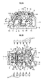
FIG. 2A and FIG. 2B are a front view and a plan view, respectively, of a vehicle body assembling device according to an embodiment of the present invention. -
FIG. 3 is a flowchart illustrating a process carried out by the vehicle body assembling device inFIG. 2 . -
FIG. 4 is a diagram illustrating exemplary welding spots in welding steps in the process inFIG. 3 . - The following will describe an embodiment of the present invention with reference to the accompanying drawings. An inner frame of a vehicle body formed by a vehicle body assembling device according to the embodiment is formed by using a floor complete 1 serving as a floor assembly, a
roof arch 2, two side inner completes 3 serving as side inner assemblies, and awindshield 4, as illustrated inFIG. 1 . Theroof arch 2 is composed of afront roof arch 5, acenter roof arch 6, and arear roof arch 7. - As illustrated in
FIG. 2 , the vehicle body assembling device according to the embodiment is provided withwelding robots 8 serving as welding units, afirst jig 9, which holds the floor complete 1 positioned in a state in which the floor complete 1 is positioned at a predetermined holding position, asecond jig 10, which holds theroof arch 2 and thewindshield 4 in a state in which theroof arch 2 and thewindshield 4 are positioned at predetermined holding positions, and front connectingunits 11 and rear connectingunits 12, which interconnect thefirst jig 9 and thesecond jig 10. - The front connecting
units 11 and the rear connectingunits 12 connect thefirst jig 9 holding the floor complete 1 and thesecond jig 10 holding theroof arch 2 and thewindshield 4 thereby to mutually position the floor complete 1, theroof arch 2, and thewindshield 4. The front connectingunits 11 and the rear connectingunits 12 are respectively provided two each at positions that are symmetrical in the right and left direction of the vehicle body. - The
first jig 9 and thesecond jig 10 have functions for holding the side inner completes 3 in a state in which the side inner completes 3 are partly in contact with and are positioned relative to the floor complete 1, theroof arch 2, and thewindshield 4, which are positioned by the front connectingunits 11 and the rear connectingunits 12. Thewelding robots 8 connect, by welding, the floor complete 1, theroof arch 2, thewindshield 4, and the side inner completes 3, which are held by thefirst jig 9 and thesecond jig 10 as described above, thereby forming the inner frame. - The
first jig 9 supports the floor complete 1 at seating positions P1 to P4 illustrated inFIG. 2 thereby to hold the floor complete 1 in a positioned state. At the seating positions P1 and P2, draining pins are inserted for positioning. The seating positions P1 to P4 are individually defined by each pair at positions that are symmetrical in the right and left direction of the vehicle body. - Further, the
first jig 9 holds the right and left side inner completes 3 in a positioned state at holding positions P5 to P7 illustrated inFIG. 2 . The holding is accomplished by inserting positioning pins in positioning holes provided in the panels of the side inner completes 3 and by clamping the panels by using clamping members from the protruding distal end sides of the pins to the jig side. - The
second jig 10 supports thefront roof arch 5, thecenter roof arch 6, and therear roof arch 7 in a state in which these arches are positioned at holding positions P8 to P10 illustrated inFIG. 2 , and holds thewindshield 4 in a state in which thewindshield 4 is positioned at a holding position P11. The holding positions P8 to P11 are respectively defined by each pair at positions that are symmetrical in the right and left direction of the vehicle body. - The holding at the holding positions P8 to P10 is accomplished by inserting positioning pins into positioning holes provided in corresponding panels of the
roof arch 2 and by clamping each of the edges of theroof arch 2 in the front-back direction of the positioning holes. The holding at the holding position P11 is accomplished by using a clamp or the like. - Further, the
second jig 10 holds the right and left side inner completes 3 in a state in which each of thecompletes 3 are positioned at holding positions P12 to P15 illustrated inFIG. 2 . The support at the holding position P12 is accomplished by inserting positioning pins in positioning holes provided in the panels of the side inner completes 3 and by clamping a few locations in the vicinity of the positioning holes. Further, the holding at the holding positions P13 to P15 is accomplished by clamping the panels of the side inner completes 3. - Each of the front connecting
units 11 is configured of a connecting section in thefirst jig 9 side, which is provided on afront docking support 13 on thefirst jig 9, and a connecting section in thesecond jig 10 side, which is provided at a corresponding position on thesecond jig 10. Each of the rear connectingunits 12 is configured of a connecting section in thefirst jig 9 side, which is provided on arear docking support 14 on thefirst jig 9, and a connecting section in thesecond jig 10 side, which is provided at a corresponding position on thesecond jig 10. -
FIG. 3 is a flowchart illustrating the process for forming the inner frame carried out by the vehicle body assembling device. When the process for forming the inner frame is started, first, the front docking supports 13 on thefirst jig 9 are raised and kept raised, as illustrated inFIG. 3 (step S1). - Next, a first holding step for holding, by the
first jig 9, the floor complete 1 positioned in a state, in which the floor complete 1 is positioned at a predetermined holding position, is carried out (step S2). More specifically, the floor complete 1 is carried by a shuttle conveyor and transferred to thefirst jig 9. At this time, thefirst jig 9 supports the floor complete 1 at the seating positions P1 to P4 as described above. This positions the floor complete 1 with respect to thefirst jig 9 and the floor complete 1 is held by thefirst jig 9. - Subsequently, a second holding step is carried out, in which the
second jig 10 holds theroof arch 2 and thewindshield 4 in a state in which theroof arch 2 and thewindshield 4 are in a state positioned at predetermined holding positions (step S3). The holding is carried out in a state in which theroof arch 2 and thewindshield 4 are positioned at the holding positions P8 to P10 and P11 as described above. - Subsequently, a jig connecting step is carried out, in which the
first jig 9 and thesecond jig 10 are connected to mutually position the floor complete 1 and theroof arch 2, and the windshield 4 (step S4). The connection is accomplished by the front connectingunits 11 and therear connecting units 12. - Subsequently, a third holding step is carried out, in which the
first jig 9 and thesecond jig 10 hold the side inner completes 3 in a state in which the side inner completes 3 are partly in contact with and are positioned with respect to the floor complete 1, theroof arch 2, and the windshield 4 (step S5). - More specifically, carrying hands 15 (refer to
FIG. 2 ) holding the right and left side inner completes 3, respectively, move down the side inner completes 3 with the bottom ends thereof facing toward the floor complete 1. At this time, the bottom ends of the side inner completes 3 at the positions corresponding to the front docking supports 13 are open, so that the side inner completes 3 do not interfere with the front docking supports 13. - When the side inner completes 3 reach predetermined descent positions, the carrying
hands 15 move the side inner completes 3 toward the floor complete 1 and theroof arch 2. Thus, the side inner completes 3 come partly in contact with the floor complete 1, theroof arch 2, and thewindshield 4 and are positioned with respect to thefirst jig 9 and thesecond jig 10, and held by thefirst jig 9 and thesecond jig 10. - More specifically, the
first jig 9 holds the right and left side inner completes 3 in a state in which the right and left side inner completes 3 are positioned at the holding positions P5 to P7 illustrated inFIG. 2 as described above. Thesecond jig 10 holds the right and left side inner completes 3 in a state in which the right and left side inner completes 3 are individually positioned at the holding positions P12 to P15 illustrated inFIG. 2 . When the holding is completed, each of the carryinghands 15 clear the holding of the side inner completes 3 and retract. - Subsequently, welding steps are carried out to connect the floor complete 1, the
roof arch 2, the side inner completes 3, and thewindshield 4 by welding so as to form the inner frame (steps S6 to S9). The welding steps include a first welding step (step S6), a second jig retraction step (step S7), a docking support retraction step (step S8), and a second welding step (step S9). - In the first welding step (step S6), the welding is carried out at some of all welding positions. More specifically, a predetermined number of the all predetermined welding spots are spot-welded by the
welding robots 8 to connect the floor complete 1, theroof arch 2, the side inner completes 3, and thewindshield 4 to preliminarily form the inner frame. - In the second jig retraction step (step S7), the
second jig 10 clears the holding of theroof arch 2, the side inner completes 3, and thewindshield 4 and retracts to a predetermined position where thesecond jig 10 does not interfere with the second welding step (step S7). - In the docking support retraction step (step S8), the connection between the
first jig 9 and thesecond jig 10 is partly cleared. More specifically, the connection by the front connectingunits 11 is cleared and the right and left front docking supports 13 of thefirst jig 9 that was in a raised state are individually lowered outward in the right and left direction and placed at retraction positions (step S8). - Then, in the second welding step (step S9), the
welding robots 8 spot-weld the remaining welding spots. At this time, thesecond jig 10 and the front docking supports 13 do not interfere with the welding of the remaining welding spots, since thesecond jig 10 and the front docking supports 13 have been positioned in the retraction positions. Thus, the floor complete 1, theroof arch 2, the side inner completes 3, and thewindshield 4 are completely connected to each other, completing the inner frame. - Outer panels and the like are attached to the completed inner frame afterward. Thus, the vehicle body is formed.
-
FIG. 4 illustrates exemplary welding spots in the welding of the first welding step (step S6) and the second welding step (step S9) described above. As illustrated inFIG. 4 , the numbers of welding spots W1 in the first welding step and welding spots W2 in the second welding step are set to be approximately the same so as to maintain the positional relationship among the floor complete 1, theroof arch 2, the side inner completes 3, and thewindshield 4 after the second jig retraction step (step S7) and the docking support retraction step (step S8) are carried out, thus preventing the occurrence of difficulties in the welding process of the second welding step (step S9). - According to the present embodiment, the floor complete 1, the
roof arch 2, the side inner completes 3, and thewindshield 4 are welded while being held in a mutually positioned state by the first jig and the second jig, which are connected, thus forming the inner frame. This arrangement obviates the conventional need for preliminary assembly or additional welding at a plurality of processing stations, making it possible to form the inner frame from the floor complete 1, theroof arch 2, the side inner completes 3, and thewindshield 4 at a single processing station. Hence, space saving and reduced cost can be achieved in the manufacture of vehicle bodies. - Further, in the first welding step (step S6), the welding is carried out at some welding positions, at which the presence of the
second jig 10 does not interfere with the welding, to preliminarily connect the floor complete 1, theroof arch 2, the side inner completes 3, and thewindshield 4. Thereafter, the welding is carried out at the remaining welding positions after the second jig is retracted, thus making it possible to connect the floor complete 1, theroof arch 2, the side inner completes 3, and thewindshield 4 without difficulty. - Further, in this case, after the first welding step (step S6), the connection between the
first jig 9 and thesecond jig 10 by the front connectingunits 11 is cleared to retract the front docking supports 13 before the second welding step (step S9). Therefore, the welding can be carried out at the welding positions, at which the presence of the front docking supports 13 interferes with welding, without difficulty in the second welding step (step S9). - The present invention is used to form an inner frame of a vehicle body by using a floor assembly, side inner assemblies, and a roof arch. At that time, the inner frame can be formed at a single processing station.
- 1 ... Floor complete (Floor assembly) ; 2 ...Roof arch; 3 ...Side inner complete (Side inner assembly) ; 4 ...Windshield; 9 ...First jig; 10 ...Second jig; 11 ...Front connecting unit; 12 ...Rear connecting unit
Claims (4)
- A vehicle body assembling method for forming an inner frame of a vehicle body by using a floor assembly, side inner assemblies, and a roof arch, comprising:a first holding step for holding the floor assembly by a first jig in a state in which the floor assembly is positioned at a predetermined holding position;a second holding step for holding the roof arch by a second jig in a state in which the roof arch is positioned at a predetermined holding position;a jig connecting step for connecting the first jig and the second jig so as to mutually position the floor assembly and the roof arch after the first holding step and the second holding step;a third holding step for holding the side inner assemblies by the first jig and the second jig in a state, in which the side inner assemblies are partly in contact with and positioned with respect to the floor assembly and the roof arch, after the jig connecting step; anda welding step for connecting the floor assembly, the roof arch, and the side inner assemblies by welding after the third holding step, thereby forming the inner frame.
- The vehicle body assembling method according to claim 1,
wherein the welding step comprises:a first welding step for carrying out welding at some of all welding positions;a second jig retraction step for clearing the holding of the roof arch and the side inner assemblies by the second jig so as to retract the second jig to a predetermined position after the first welding step; anda second welding step for carrying out welding at remaining welding positions after the second jig retraction step. - The vehicle body assembling method according to claim 2,
wherein, after the first welding step, the connection between the first jig and the second jig is partly cleared before the second welding step. - A vehicle body assembling device for forming an inner frame of a vehicle body by using a floor assembly, side inner assemblies, and a roof arch, comprising:a welding unit;a first jig that holds the floor assembly in a state in which the floor assembly is positioned at a predetermined holding position;a second jig that holds the roof arch in a state in which the roof arch is positioned at a predetermined holding position; anda connecting unit that interconnects the first jig holding the floor assembly and the second jig holding the roof arch thereby to mutually position the floor assembly and the roof arch,wherein the first jig and the second jig have functions for holding the side inner assemblies in a state in which the side inner assemblies are partly in contact with and positioned with respect to the floor assembly and the roof arch, which are positioned by the connecting unit, andthe welding unit has a function for welding the floor assembly, the roof arch, and the side inner assemblies, which are held by the first jig and the second jig, thereby to form the inner frame.
Applications Claiming Priority (2)
| Application Number | Priority Date | Filing Date | Title |
|---|---|---|---|
| JP2012127349 | 2012-06-04 | ||
| PCT/JP2013/054321 WO2013183321A1 (en) | 2012-06-04 | 2013-02-21 | Vehicle body assembling method and vehicle body assembling device |
Publications (3)
| Publication Number | Publication Date |
|---|---|
| EP2857296A1 true EP2857296A1 (en) | 2015-04-08 |
| EP2857296A4 EP2857296A4 (en) | 2016-05-18 |
| EP2857296B1 EP2857296B1 (en) | 2021-06-30 |
Family
ID=49711723
Family Applications (1)
| Application Number | Title | Priority Date | Filing Date |
|---|---|---|---|
| EP13800018.7A Active EP2857296B1 (en) | 2012-06-04 | 2013-02-21 | Vehicle body assembling method |
Country Status (8)
| Country | Link |
|---|---|
| US (1) | US9371100B2 (en) |
| EP (1) | EP2857296B1 (en) |
| JP (1) | JP5877899B2 (en) |
| CN (1) | CN104334445B (en) |
| BR (1) | BR112014029960B1 (en) |
| CA (1) | CA2874063C (en) |
| MX (1) | MX354794B (en) |
| WO (1) | WO2013183321A1 (en) |
Cited By (2)
| Publication number | Priority date | Publication date | Assignee | Title |
|---|---|---|---|---|
| FR3073810A1 (en) * | 2017-11-17 | 2019-05-24 | Psa Automobiles Sa | METHOD AND STATION FOR AUTOMATED LOADING OF ROOF TRAVERS ON A BOX FRAME OF A MOTOR VEHICLE |
| CN113458643A (en) * | 2021-08-08 | 2021-10-01 | 南京中车浦镇城轨车辆有限责任公司 | Modular railway vehicle side roof assembly welding method and vehicle roof assembly method |
Families Citing this family (7)
| Publication number | Priority date | Publication date | Assignee | Title |
|---|---|---|---|---|
| JP2015027838A (en) * | 2013-07-30 | 2015-02-12 | 富士重工業株式会社 | Body manufacturing method |
| JP5819461B2 (en) * | 2014-03-25 | 2015-11-24 | 本田技研工業株式会社 | Body assembly method and body assembly jig |
| CN107614367B (en) * | 2015-06-04 | 2020-04-28 | 本田技研工业株式会社 | Vehicle body assembling method and vehicle body assembling device |
| JP6304779B2 (en) * | 2016-09-29 | 2018-04-04 | 本田技研工業株式会社 | Manufacturing method and apparatus for vehicle body assembly |
| CN107458500B (en) * | 2017-06-26 | 2019-06-21 | 北京长城华冠汽车科技股份有限公司 | A method of assembling a body frame |
| JP7135528B2 (en) * | 2018-07-18 | 2022-09-13 | マツダ株式会社 | Car body assembly equipment and car body assembly method |
| CN109014638B (en) * | 2018-08-20 | 2021-01-22 | 北京长城华冠汽车科技股份有限公司 | Welding method of frame type aluminum alloy body assembly |
Family Cites Families (8)
| Publication number | Priority date | Publication date | Assignee | Title |
|---|---|---|---|---|
| GB2133749B (en) * | 1982-12-22 | 1986-03-19 | Honda Motor Co Ltd | Vehicle body assembling system |
| JPS6112474A (en) | 1984-06-26 | 1986-01-20 | Toyota Motor Corp | Vehicle body assembling device |
| MX163623B (en) * | 1987-04-17 | 1992-06-08 | Honda Motor Co Ltd | METHOD FOR ASSEMBLING A VEHICLE BODY FROM A TWO-WHEEL VEHICLE AND AN ASSEMBLY DEVICE FOR THE SAME |
| JPH0811553B2 (en) * | 1987-09-03 | 1996-02-07 | 日産自動車株式会社 | Body assembly method |
| JP3153286B2 (en) * | 1991-09-05 | 2001-04-03 | マツダ株式会社 | Automotive sun-roof structure and sun-roof assembling method |
| JPH0811553A (en) | 1994-07-01 | 1996-01-16 | Nissan Motor Co Ltd | Atmosphere temperature control device in engine room |
| JP4364402B2 (en) | 2000-05-24 | 2009-11-18 | 三洋機工株式会社 | Body assembly method and assembly apparatus |
| JP4631881B2 (en) * | 2007-07-30 | 2011-02-16 | トヨタ自動車株式会社 | Work transfer device |
-
2013
- 2013-02-21 CA CA2874063A patent/CA2874063C/en active Active
- 2013-02-21 US US14/403,328 patent/US9371100B2/en active Active
- 2013-02-21 JP JP2014519852A patent/JP5877899B2/en active Active
- 2013-02-21 EP EP13800018.7A patent/EP2857296B1/en active Active
- 2013-02-21 MX MX2014014835A patent/MX354794B/en active IP Right Grant
- 2013-02-21 CN CN201380029537.4A patent/CN104334445B/en active Active
- 2013-02-21 WO PCT/JP2013/054321 patent/WO2013183321A1/en not_active Ceased
- 2013-02-21 BR BR112014029960-9A patent/BR112014029960B1/en not_active IP Right Cessation
Cited By (2)
| Publication number | Priority date | Publication date | Assignee | Title |
|---|---|---|---|---|
| FR3073810A1 (en) * | 2017-11-17 | 2019-05-24 | Psa Automobiles Sa | METHOD AND STATION FOR AUTOMATED LOADING OF ROOF TRAVERS ON A BOX FRAME OF A MOTOR VEHICLE |
| CN113458643A (en) * | 2021-08-08 | 2021-10-01 | 南京中车浦镇城轨车辆有限责任公司 | Modular railway vehicle side roof assembly welding method and vehicle roof assembly method |
Also Published As
| Publication number | Publication date |
|---|---|
| EP2857296A4 (en) | 2016-05-18 |
| BR112014029960A2 (en) | 2017-06-27 |
| CN104334445B (en) | 2016-09-07 |
| CA2874063A1 (en) | 2013-12-12 |
| BR112014029960B1 (en) | 2022-06-21 |
| WO2013183321A1 (en) | 2013-12-12 |
| CN104334445A (en) | 2015-02-04 |
| US9371100B2 (en) | 2016-06-21 |
| JPWO2013183321A1 (en) | 2016-01-28 |
| MX354794B (en) | 2018-03-21 |
| US20150102089A1 (en) | 2015-04-16 |
| JP5877899B2 (en) | 2016-03-08 |
| EP2857296B1 (en) | 2021-06-30 |
| CA2874063C (en) | 2017-03-21 |
| MX2014014835A (en) | 2015-07-06 |
Similar Documents
| Publication | Publication Date | Title |
|---|---|---|
| EP2857296B1 (en) | Vehicle body assembling method | |
| US9776286B2 (en) | Method of manufacturing a vehicle body and a vehicle body | |
| JP2002517356A (en) | How to make a car body | |
| JP6092909B2 (en) | Body manufacturing equipment | |
| EP2745955A2 (en) | Process for joining aircraft structural components | |
| CN106163734B (en) | Body assembly system and body assembly method | |
| JP4968938B2 (en) | Body part positioning device and body part positioning method | |
| CN105636860B (en) | Production system and method for manufacturing different body-in-white component variants | |
| EP3042734A1 (en) | Method for welding upper rail of seat track for vehicle seat and adaptor bracket | |
| US10046442B2 (en) | Vehicle body manufacturing apparatus | |
| CN107000801B (en) | Method and device for assembling automobile body | |
| US8181347B2 (en) | Geometrical conformation unit | |
| JP4364402B2 (en) | Body assembly method and assembly apparatus | |
| CN210848873U (en) | Vehicle body side wall assembly device | |
| US20130111728A1 (en) | Component fastening location system | |
| JPH07164187A (en) | Compound type welding jig and welding method using the same | |
| KR101458594B1 (en) | System for assembling car body parts | |
| KR101468177B1 (en) | System for marrying car body panel | |
| JP7135528B2 (en) | Car body assembly equipment and car body assembly method | |
| JP7166978B2 (en) | Side member manufacturing method and side member assembly line | |
| JPS62160971A (en) | Assembly method for car body | |
| JP2000288847A (en) | Building unit assembling apparatus and assembling method | |
| JP2018097969A (en) | Manufacturing device of harness bundle and manufacturing method of harness bundle |
Legal Events
| Date | Code | Title | Description |
|---|---|---|---|
| PUAI | Public reference made under article 153(3) epc to a published international application that has entered the european phase |
Free format text: ORIGINAL CODE: 0009012 |
|
| 17P | Request for examination filed |
Effective date: 20141124 |
|
| AK | Designated contracting states |
Kind code of ref document: A1 Designated state(s): AL AT BE BG CH CY CZ DE DK EE ES FI FR GB GR HR HU IE IS IT LI LT LU LV MC MK MT NL NO PL PT RO RS SE SI SK SM TR |
|
| AX | Request for extension of the european patent |
Extension state: BA ME |
|
| DAX | Request for extension of the european patent (deleted) | ||
| RA4 | Supplementary search report drawn up and despatched (corrected) |
Effective date: 20160419 |
|
| RIC1 | Information provided on ipc code assigned before grant |
Ipc: B23K 101/00 20060101ALI20160413BHEP Ipc: B23K 37/04 20060101ALI20160413BHEP Ipc: B23P 21/00 20060101ALI20160413BHEP Ipc: B62D 65/02 20060101ALI20160413BHEP Ipc: B23P 19/04 20060101ALI20160413BHEP Ipc: B23K 103/20 20060101ALI20160413BHEP Ipc: B62D 65/00 20060101AFI20160413BHEP Ipc: B23K 103/10 20060101ALI20160413BHEP Ipc: B23P 19/00 20060101ALI20160413BHEP Ipc: B23K 31/02 20060101ALI20160413BHEP Ipc: B23K 37/047 20060101ALI20160413BHEP Ipc: B23K 101/18 20060101ALI20160413BHEP |
|
| STAA | Information on the status of an ep patent application or granted ep patent |
Free format text: STATUS: EXAMINATION IS IN PROGRESS |
|
| 17Q | First examination report despatched |
Effective date: 20180622 |
|
| GRAP | Despatch of communication of intention to grant a patent |
Free format text: ORIGINAL CODE: EPIDOSNIGR1 |
|
| STAA | Information on the status of an ep patent application or granted ep patent |
Free format text: STATUS: GRANT OF PATENT IS INTENDED |
|
| INTG | Intention to grant announced |
Effective date: 20210129 |
|
| GRAS | Grant fee paid |
Free format text: ORIGINAL CODE: EPIDOSNIGR3 |
|
| GRAA | (expected) grant |
Free format text: ORIGINAL CODE: 0009210 |
|
| STAA | Information on the status of an ep patent application or granted ep patent |
Free format text: STATUS: THE PATENT HAS BEEN GRANTED |
|
| AK | Designated contracting states |
Kind code of ref document: B1 Designated state(s): AL AT BE BG CH CY CZ DE DK EE ES FI FR GB GR HR HU IE IS IT LI LT LU LV MC MK MT NL NO PL PT RO RS SE SI SK SM TR |
|
| REG | Reference to a national code |
Ref country code: GB Ref legal event code: FG4D Ref country code: CH Ref legal event code: EP |
|
| REG | Reference to a national code |
Ref country code: DE Ref legal event code: R096 Ref document number: 602013078161 Country of ref document: DE Ref country code: AT Ref legal event code: REF Ref document number: 1406130 Country of ref document: AT Kind code of ref document: T Effective date: 20210715 |
|
| REG | Reference to a national code |
Ref country code: IE Ref legal event code: FG4D |
|
| REG | Reference to a national code |
Ref country code: LT Ref legal event code: MG9D |
|
| PG25 | Lapsed in a contracting state [announced via postgrant information from national office to epo] |
Ref country code: FI Free format text: LAPSE BECAUSE OF FAILURE TO SUBMIT A TRANSLATION OF THE DESCRIPTION OR TO PAY THE FEE WITHIN THE PRESCRIBED TIME-LIMIT Effective date: 20210630 Ref country code: BG Free format text: LAPSE BECAUSE OF FAILURE TO SUBMIT A TRANSLATION OF THE DESCRIPTION OR TO PAY THE FEE WITHIN THE PRESCRIBED TIME-LIMIT Effective date: 20210930 Ref country code: HR Free format text: LAPSE BECAUSE OF FAILURE TO SUBMIT A TRANSLATION OF THE DESCRIPTION OR TO PAY THE FEE WITHIN THE PRESCRIBED TIME-LIMIT Effective date: 20210630 |
|
| REG | Reference to a national code |
Ref country code: NL Ref legal event code: MP Effective date: 20210630 |
|
| REG | Reference to a national code |
Ref country code: AT Ref legal event code: MK05 Ref document number: 1406130 Country of ref document: AT Kind code of ref document: T Effective date: 20210630 |
|
| PG25 | Lapsed in a contracting state [announced via postgrant information from national office to epo] |
Ref country code: NO Free format text: LAPSE BECAUSE OF FAILURE TO SUBMIT A TRANSLATION OF THE DESCRIPTION OR TO PAY THE FEE WITHIN THE PRESCRIBED TIME-LIMIT Effective date: 20210930 Ref country code: SE Free format text: LAPSE BECAUSE OF FAILURE TO SUBMIT A TRANSLATION OF THE DESCRIPTION OR TO PAY THE FEE WITHIN THE PRESCRIBED TIME-LIMIT Effective date: 20210630 Ref country code: RS Free format text: LAPSE BECAUSE OF FAILURE TO SUBMIT A TRANSLATION OF THE DESCRIPTION OR TO PAY THE FEE WITHIN THE PRESCRIBED TIME-LIMIT Effective date: 20210630 Ref country code: GR Free format text: LAPSE BECAUSE OF FAILURE TO SUBMIT A TRANSLATION OF THE DESCRIPTION OR TO PAY THE FEE WITHIN THE PRESCRIBED TIME-LIMIT Effective date: 20211001 Ref country code: LV Free format text: LAPSE BECAUSE OF FAILURE TO SUBMIT A TRANSLATION OF THE DESCRIPTION OR TO PAY THE FEE WITHIN THE PRESCRIBED TIME-LIMIT Effective date: 20210630 |
|
| PG25 | Lapsed in a contracting state [announced via postgrant information from national office to epo] |
Ref country code: EE Free format text: LAPSE BECAUSE OF FAILURE TO SUBMIT A TRANSLATION OF THE DESCRIPTION OR TO PAY THE FEE WITHIN THE PRESCRIBED TIME-LIMIT Effective date: 20210630 Ref country code: CZ Free format text: LAPSE BECAUSE OF FAILURE TO SUBMIT A TRANSLATION OF THE DESCRIPTION OR TO PAY THE FEE WITHIN THE PRESCRIBED TIME-LIMIT Effective date: 20210630 Ref country code: SK Free format text: LAPSE BECAUSE OF FAILURE TO SUBMIT A TRANSLATION OF THE DESCRIPTION OR TO PAY THE FEE WITHIN THE PRESCRIBED TIME-LIMIT Effective date: 20210630 Ref country code: SM Free format text: LAPSE BECAUSE OF FAILURE TO SUBMIT A TRANSLATION OF THE DESCRIPTION OR TO PAY THE FEE WITHIN THE PRESCRIBED TIME-LIMIT Effective date: 20210630 Ref country code: PT Free format text: LAPSE BECAUSE OF FAILURE TO SUBMIT A TRANSLATION OF THE DESCRIPTION OR TO PAY THE FEE WITHIN THE PRESCRIBED TIME-LIMIT Effective date: 20211102 Ref country code: NL Free format text: LAPSE BECAUSE OF FAILURE TO SUBMIT A TRANSLATION OF THE DESCRIPTION OR TO PAY THE FEE WITHIN THE PRESCRIBED TIME-LIMIT Effective date: 20210630 Ref country code: RO Free format text: LAPSE BECAUSE OF FAILURE TO SUBMIT A TRANSLATION OF THE DESCRIPTION OR TO PAY THE FEE WITHIN THE PRESCRIBED TIME-LIMIT Effective date: 20210630 Ref country code: ES Free format text: LAPSE BECAUSE OF FAILURE TO SUBMIT A TRANSLATION OF THE DESCRIPTION OR TO PAY THE FEE WITHIN THE PRESCRIBED TIME-LIMIT Effective date: 20210630 Ref country code: AT Free format text: LAPSE BECAUSE OF FAILURE TO SUBMIT A TRANSLATION OF THE DESCRIPTION OR TO PAY THE FEE WITHIN THE PRESCRIBED TIME-LIMIT Effective date: 20210630 |
|
| PG25 | Lapsed in a contracting state [announced via postgrant information from national office to epo] |
Ref country code: PL Free format text: LAPSE BECAUSE OF FAILURE TO SUBMIT A TRANSLATION OF THE DESCRIPTION OR TO PAY THE FEE WITHIN THE PRESCRIBED TIME-LIMIT Effective date: 20210630 |
|
| REG | Reference to a national code |
Ref country code: DE Ref legal event code: R097 Ref document number: 602013078161 Country of ref document: DE |
|
| PG25 | Lapsed in a contracting state [announced via postgrant information from national office to epo] |
Ref country code: DK Free format text: LAPSE BECAUSE OF FAILURE TO SUBMIT A TRANSLATION OF THE DESCRIPTION OR TO PAY THE FEE WITHIN THE PRESCRIBED TIME-LIMIT Effective date: 20210630 |
|
| PGFP | Annual fee paid to national office [announced via postgrant information from national office to epo] |
Ref country code: DE Payment date: 20220222 Year of fee payment: 10 |
|
| PLBE | No opposition filed within time limit |
Free format text: ORIGINAL CODE: 0009261 |
|
| STAA | Information on the status of an ep patent application or granted ep patent |
Free format text: STATUS: NO OPPOSITION FILED WITHIN TIME LIMIT |
|
| PG25 | Lapsed in a contracting state [announced via postgrant information from national office to epo] |
Ref country code: AL Free format text: LAPSE BECAUSE OF FAILURE TO SUBMIT A TRANSLATION OF THE DESCRIPTION OR TO PAY THE FEE WITHIN THE PRESCRIBED TIME-LIMIT Effective date: 20210630 |
|
| 26N | No opposition filed |
Effective date: 20220331 |
|
| PG25 | Lapsed in a contracting state [announced via postgrant information from national office to epo] |
Ref country code: IT Free format text: LAPSE BECAUSE OF FAILURE TO SUBMIT A TRANSLATION OF THE DESCRIPTION OR TO PAY THE FEE WITHIN THE PRESCRIBED TIME-LIMIT Effective date: 20210630 |
|
| REG | Reference to a national code |
Ref country code: DE Ref legal event code: R084 Ref document number: 602013078161 Country of ref document: DE |
|
| REG | Reference to a national code |
Ref country code: GB Ref legal event code: 746 Effective date: 20220803 |
|
| PG25 | Lapsed in a contracting state [announced via postgrant information from national office to epo] |
Ref country code: MC Free format text: LAPSE BECAUSE OF FAILURE TO SUBMIT A TRANSLATION OF THE DESCRIPTION OR TO PAY THE FEE WITHIN THE PRESCRIBED TIME-LIMIT Effective date: 20210630 |
|
| REG | Reference to a national code |
Ref country code: CH Ref legal event code: PL |
|
| REG | Reference to a national code |
Ref country code: BE Ref legal event code: MM Effective date: 20220228 |
|
| PG25 | Lapsed in a contracting state [announced via postgrant information from national office to epo] |
Ref country code: LU Free format text: LAPSE BECAUSE OF NON-PAYMENT OF DUE FEES Effective date: 20220221 |
|
| PG25 | Lapsed in a contracting state [announced via postgrant information from national office to epo] |
Ref country code: FR Free format text: LAPSE BECAUSE OF NON-PAYMENT OF DUE FEES Effective date: 20220228 |
|
| PG25 | Lapsed in a contracting state [announced via postgrant information from national office to epo] |
Ref country code: LI Free format text: LAPSE BECAUSE OF NON-PAYMENT OF DUE FEES Effective date: 20220228 Ref country code: IE Free format text: LAPSE BECAUSE OF NON-PAYMENT OF DUE FEES Effective date: 20220221 Ref country code: CH Free format text: LAPSE BECAUSE OF NON-PAYMENT OF DUE FEES Effective date: 20220228 |
|
| PGFP | Annual fee paid to national office [announced via postgrant information from national office to epo] |
Ref country code: GB Payment date: 20221230 Year of fee payment: 11 |
|
| PG25 | Lapsed in a contracting state [announced via postgrant information from national office to epo] |
Ref country code: BE Free format text: LAPSE BECAUSE OF NON-PAYMENT OF DUE FEES Effective date: 20220228 |
|
| PG25 | Lapsed in a contracting state [announced via postgrant information from national office to epo] |
Ref country code: LT Free format text: LAPSE BECAUSE OF FAILURE TO SUBMIT A TRANSLATION OF THE DESCRIPTION OR TO PAY THE FEE WITHIN THE PRESCRIBED TIME-LIMIT Effective date: 20210630 |
|
| REG | Reference to a national code |
Ref country code: DE Ref legal event code: R119 Ref document number: 602013078161 Country of ref document: DE |
|
| PG25 | Lapsed in a contracting state [announced via postgrant information from national office to epo] |
Ref country code: DE Free format text: LAPSE BECAUSE OF NON-PAYMENT OF DUE FEES Effective date: 20230901 |
|
| PG25 | Lapsed in a contracting state [announced via postgrant information from national office to epo] |
Ref country code: HU Free format text: LAPSE BECAUSE OF FAILURE TO SUBMIT A TRANSLATION OF THE DESCRIPTION OR TO PAY THE FEE WITHIN THE PRESCRIBED TIME-LIMIT; INVALID AB INITIO Effective date: 20130221 |
|
| PG25 | Lapsed in a contracting state [announced via postgrant information from national office to epo] |
Ref country code: MK Free format text: LAPSE BECAUSE OF FAILURE TO SUBMIT A TRANSLATION OF THE DESCRIPTION OR TO PAY THE FEE WITHIN THE PRESCRIBED TIME-LIMIT Effective date: 20210630 Ref country code: CY Free format text: LAPSE BECAUSE OF FAILURE TO SUBMIT A TRANSLATION OF THE DESCRIPTION OR TO PAY THE FEE WITHIN THE PRESCRIBED TIME-LIMIT Effective date: 20210630 |
|
| PG25 | Lapsed in a contracting state [announced via postgrant information from national office to epo] |
Ref country code: TR Free format text: LAPSE BECAUSE OF FAILURE TO SUBMIT A TRANSLATION OF THE DESCRIPTION OR TO PAY THE FEE WITHIN THE PRESCRIBED TIME-LIMIT Effective date: 20210630 |
|
| PG25 | Lapsed in a contracting state [announced via postgrant information from national office to epo] |
Ref country code: MT Free format text: LAPSE BECAUSE OF FAILURE TO SUBMIT A TRANSLATION OF THE DESCRIPTION OR TO PAY THE FEE WITHIN THE PRESCRIBED TIME-LIMIT Effective date: 20210630 |
|
| GBPC | Gb: european patent ceased through non-payment of renewal fee |
Effective date: 20240221 |
|
| PG25 | Lapsed in a contracting state [announced via postgrant information from national office to epo] |
Ref country code: GB Free format text: LAPSE BECAUSE OF NON-PAYMENT OF DUE FEES Effective date: 20240221 |
|
| PG25 | Lapsed in a contracting state [announced via postgrant information from national office to epo] |
Ref country code: GB Free format text: LAPSE BECAUSE OF NON-PAYMENT OF DUE FEES Effective date: 20240221 |