EP2857255A1 - Train control device - Google Patents
Train control device Download PDFInfo
- Publication number
- EP2857255A1 EP2857255A1 EP13796521.6A EP13796521A EP2857255A1 EP 2857255 A1 EP2857255 A1 EP 2857255A1 EP 13796521 A EP13796521 A EP 13796521A EP 2857255 A1 EP2857255 A1 EP 2857255A1
- Authority
- EP
- European Patent Office
- Prior art keywords
- train
- running
- time
- plan
- speed
- Prior art date
- Legal status (The legal status is an assumption and is not a legal conclusion. Google has not performed a legal analysis and makes no representation as to the accuracy of the status listed.)
- Withdrawn
Links
- 238000001514 detection method Methods 0.000 claims abstract description 15
- 238000010586 diagram Methods 0.000 claims description 50
- 238000013459 approach Methods 0.000 claims description 3
- 238000004904 shortening Methods 0.000 claims 1
- 238000004891 communication Methods 0.000 description 9
- 238000000034 method Methods 0.000 description 5
- 238000012986 modification Methods 0.000 description 3
- 230000004048 modification Effects 0.000 description 3
- 230000001133 acceleration Effects 0.000 description 2
- 230000001360 synchronised effect Effects 0.000 description 2
- 230000006399 behavior Effects 0.000 description 1
- 238000007796 conventional method Methods 0.000 description 1
- 230000001934 delay Effects 0.000 description 1
- 230000003111 delayed effect Effects 0.000 description 1
- 230000006870 function Effects 0.000 description 1
- 230000000977 initiatory effect Effects 0.000 description 1
Images


Classifications
-
- B61L15/0058—
-
- B—PERFORMING OPERATIONS; TRANSPORTING
- B61—RAILWAYS
- B61L—GUIDING RAILWAY TRAFFIC; ENSURING THE SAFETY OF RAILWAY TRAFFIC
- B61L27/00—Central railway traffic control systems; Trackside control; Communication systems specially adapted therefor
- B61L27/10—Operations, e.g. scheduling or time tables
- B61L27/12—Preparing schedules
-
- B61L15/0062—
-
- B—PERFORMING OPERATIONS; TRANSPORTING
- B61—RAILWAYS
- B61L—GUIDING RAILWAY TRAFFIC; ENSURING THE SAFETY OF RAILWAY TRAFFIC
- B61L25/00—Recording or indicating positions or identities of vehicles or vehicle trains or setting of track apparatus
- B61L25/02—Indicating or recording positions or identities of vehicles or vehicle trains
- B61L25/021—Measuring and recording of train speed
-
- B—PERFORMING OPERATIONS; TRANSPORTING
- B61—RAILWAYS
- B61L—GUIDING RAILWAY TRAFFIC; ENSURING THE SAFETY OF RAILWAY TRAFFIC
- B61L25/00—Recording or indicating positions or identities of vehicles or vehicle trains or setting of track apparatus
- B61L25/02—Indicating or recording positions or identities of vehicles or vehicle trains
- B61L25/025—Absolute localisation, e.g. providing geodetic coordinates
-
- B—PERFORMING OPERATIONS; TRANSPORTING
- B61—RAILWAYS
- B61L—GUIDING RAILWAY TRAFFIC; ENSURING THE SAFETY OF RAILWAY TRAFFIC
- B61L25/00—Recording or indicating positions or identities of vehicles or vehicle trains or setting of track apparatus
- B61L25/02—Indicating or recording positions or identities of vehicles or vehicle trains
- B61L25/026—Relative localisation, e.g. using odometer
-
- B—PERFORMING OPERATIONS; TRANSPORTING
- B61—RAILWAYS
- B61L—GUIDING RAILWAY TRAFFIC; ENSURING THE SAFETY OF RAILWAY TRAFFIC
- B61L27/00—Central railway traffic control systems; Trackside control; Communication systems specially adapted therefor
- B61L27/10—Operations, e.g. scheduling or time tables
- B61L27/14—Following schedules
-
- B—PERFORMING OPERATIONS; TRANSPORTING
- B61—RAILWAYS
- B61L—GUIDING RAILWAY TRAFFIC; ENSURING THE SAFETY OF RAILWAY TRAFFIC
- B61L15/00—Indicators provided on the vehicle or vehicle train for signalling purposes ; On-board control or communication systems
- B61L15/0018—Communication with or on the vehicle or vehicle train
- B61L15/0027—Radio-based, e.g. using GSM-R
-
- B—PERFORMING OPERATIONS; TRANSPORTING
- B61—RAILWAYS
- B61L—GUIDING RAILWAY TRAFFIC; ENSURING THE SAFETY OF RAILWAY TRAFFIC
- B61L3/00—Devices along the route for controlling devices on the vehicle or vehicle train, e.g. to release brake, to operate a warning signal
- B61L3/16—Continuous control along the route
- B61L3/22—Continuous control along the route using magnetic or electrostatic induction; using electromagnetic radiation
- B61L3/221—Continuous control along the route using magnetic or electrostatic induction; using electromagnetic radiation using track circuits
Definitions
- Embodiments of the present invention relate to a train control device.
- vehicles such as trains comprise an automatic train operation (ATO) to maintain stable operation and reduce possibility of delays.
- ATO automatic train operation
- the ATO generates, in advance, a running plan for a section from one station to the next stop station, and perform various kinds of controls such as speed control and brake control in accordance with the running plan.
- Patent Literature 1 Japanese Patent Application Laid-open No. 2003-235116
- the running plan in the ATO is calculated according to railroad data or vehicle model data so that a running time of the running plan becomes close to a predetermined running time determined for each distance between stations.
- the running plan is not created by taking into account an arrival time at the next station. Therefore, according to the above-mentioned conventional technique, when a train leaves a station with a delay behind a train operation diagram, the train may arrive at the next station with a delay behind the train operation diagram.
- a train control device of an embodiment comprises a detection unit, a clock unit, a diagram input unit, and a calculating unit.
- the detection unit detects a current position and a speed of a train.
- the clock unit keeps a current time.
- the diagram input unit inputs diagram data including a scheduled arrival time of the train at each of stations on a route.
- the calculating unit calculates a running plan to a next station based on a target running time obtained by subtracting the current time from a scheduled arrival time at the next station included in the input diagram data, the detected current position, the detected speed, operational characteristics of the train, and a route condition.
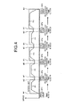
- FIG. 1 is a block diagram illustrating an configuration of a train control device 1 according to a first embodiment.
- a train T is provided with the train control device 1 and a drive and brake control device 3 that drives and brakes the train T according to a drive instruction or a brake instruction from the train control device 1.
- the train T runs on a rail R as the drive and brake control device 3 drives and brakes wheels 2.
- the drive and brake control device 3 includes an inverter for controlling a motor and a brake control device for performing cooperative control of air braking by the brake device and electric braking by the motor.
- the train control device 1 includes a speed and position detection unit 10, an automatic train control (ATC) on-vehicle device 20, an ATO device 30, a diagram input unit 31, a database 32, a clock unit 33, and a display device 60.
- the speed and position detection unit 10 detects the speed of the train T running on the rail R and position of the train T on the route. Specifically, the speed and position detection unit 10 detects the speed of the train T based on an output value from a tacho generator (TG) 12 linked with rotation of the wheels 2.
- TG tacho generator
- PG pulse generator
- the speed and position detection unit 10 also detects the current position of the train T on the route, based on a running distance obtained by integrating the speed of the train T and a signal from a ground coil 13 received by a pickup coil 11.
- the speed and current position of the train T detected by the speed and position detection unit 10 are output as speed and position information to the ATC on-vehicle device 20 and the ATO device 30.
- the ATC on-vehicle device 20 receives, via a power receiver 21, information provided by an ATC ground device 22 as an analog signal via a track circuit 23 formed by using the rail R.
- the ATC on-vehicle device 20 outputs a brake instruction to the drive and brake control device 3 based on the information output from the ATC ground device 22 and the speed of the train T.
- the information from the ATC ground device 22 includes a signal aspect indicating a speed limit (hereinafter referred to as "aspect speed limit”) for a blocked section where the train T resides.
- the ATC on-vehicle device 20 compares the aspect speed limit output from the ATC ground device 22 with the speed of the train T.
- the ATC on-vehicle device 20 If the speed of the train T exceeds the aspect speed limit, the ATC on-vehicle device 20 outputs a brake instruction to the drive and brake control device 3. The ATC on-vehicle device 20 also outputs the aspect speed limit received via the power receiver 21 to the ATO device 30.
- the ATO device 30 outputs a drive instruction or a brake instruction to the drive and brake control device 3 under the ATC on-vehicle device 20. Specifically, the ATO device 30 outputs to the drive and brake control device 3 a control instruction (notch instruction) such as a drive instruction or a brake instruction based on the speed and current position of the train T detected by the speed and position detection unit 10. Accordingly, the train T runs at a speed within a range at which the speed does not exceed the signal-indicative speed output from the ATC on-vehicle device 20, and stop the train T at a predetermined position in a station.
- a control instruction notch instruction
- the ATO device 30 also calculates a running plan for the train T at the current position and the speed detected by the speed and position detection unit 10 to arrive at the next station according to operation characteristics of the train T and route conditions (detailed descriptions will be provided later).
- the running plan includes data defining sections to which driving operation, coasting operation, and braking operation are assigned, and further includes running curves, in order to run and stop the train T at a target position in the next station on a predetermined running time.
- the ATO device 30 operates the train T according to the calculated running plan.
- the ATO device 30 When performing automatic operation, the ATO device 30 outputs a drive instruction or a brake instruction to the drive and brake control device 3 based on the running plan. The train control device 1 then automatically operates the train T according to the running plan.
- the ATO device 30 When performing manual operation, the ATO device 30 causes the display device 60 installed in the driver's platform to display a target speed based on the running plan. The driver manipulates a master controller (not illustrated) to follow the target speed displayed on the display device 60. Thus, the train T can manually be operated according to the running plan.
- the diagram input unit 31 receives diagram data including scheduled arrival (passage) times of the train T at individual stations on the route. For example, the diagram input unit 31 obtains the diagram data through wireless communication via a communication device 40 or obtains the diagram data from a memory unit 52, such as an IC card, of a duty card 51 connected to an I/F device 50, or the like. The diagram data input from the diagram input unit 31 is recorded as operational conditions in the database 32.
- the diagram data for each of trains running on the route is managed in management center 41.
- the diagram data is sent, via a telecommunication line to a station management device 42 on the route of the train T.
- the station management device 42 provides the train T with the diagram data for the train T obtained from the operation management center 41 by performing wireless-communications with the communication device 40 installed in the train T or by writing to the memory unit 52 of the duty card 51 inserted by the driver into the I/F device 50 at the start of operation.
- the communication device 40 is a device for performing wireless-communications with the station management device 42, receive GPS signals, and the like.
- the communication device 40 receives, via wireless, the diagram data output from the station management device 42 and forwards the diagram data to the diagram input unit 31.
- the I/F device 50 is a card reader or the like to read the diagram data from the memory unit 52 of the duty card 51 and output the diagram data to the diagram input unit 31.
- the database 32 stores data necessary for operation of the train T such as route conditions (gradients, curvatures, speed limits, and/or the like), operational conditions (target stop positions at individual stations, diagram data including scheduled passage or arrival times at individual stations, and/or the like), and vehicle characteristics (vehicle weight, train operation characteristics such as acceleration/deceleration performance, and/or the like).
- the database 32 may be a hard disc installed in the train T or an IC card carried by the driver or the like. In the case of an IC card, the driver can use the database 32 by inserting the IC card into the I/F device 50 when initiating operation.
- the clock unit 33 has real time clock (RTC) function to keep the current time.
- the current time kept by the clock unit 33 is output to the ATO device 30. It is assumed that the current time kept by the clock unit 33 is synchronized with the current time referenced by the operation management center 41 when generating the diagram data. Specifically, the current time is to be synchronized with GPS time included in the GPS signal at the operation management center 41 and the train T. Also, the synchronization of the current time of the clock unit 33 with the current time used by the operation management center 41 may be performed by wireless-communications during stopping at stations.
- FIG. 2 is a flowchart illustrating one example of operations performed by the train control device 1 according to the first embodiment.
- the ATO device 30 obtains the current position and current speed of the train T from the speed and position detection unit 10 and further obtains the current time from the clock unit 33 (S1). Then, the ATO device 30 determines whether a running plan for getting to the next station has been prepared (S2). Here, the ATO device 30 determines that no running plan to the next station has been prepared when the train T is standing by for leaving or the next station data has been updated at S14, because such a running plan is yet to be calculated. Otherwise, the ATO device 30 determines that a running plan to the next station has been prepared when the train T is running according to the calculated running plan.
- the ATO device 30 refers to the diagram data included in the operational conditions input by the diagram input unit 31 and recorded in the database 32 to obtain the scheduled arrival (passage) time at the next station (S3).
- the ATO device 30 calculates the target running time by subtracting the current time from the scheduled arrival (passage) time at the next station (S4), and calculates a running plan in which the running time becomes close to the target running time based on the route conditions and vehicle characteristics recorded in the database 32 (S5). Accordingly, the ATO device 30 performs automatic operation or manual operation according to the calculated running plan.
- FIG. 3 is a conceptual diagram for exemplifying a running plan P.
- the train T is stopping at a station ST1 and has a scheduled arrival time at 12:02:30 at a next station ST2.
- the target running time between the stations ST1 and ST2 becomes 0:02:12.
- the ATO device 30 calculates the running plan P to define sections and running curves for driving operation, coasting operation, and braking operation so that the running time based on the running plan becomes close to the target running time between the stations ST1 and ST2 and follows the speed limit in the route conditions recorded in the database 32.
- the running plan P is calculated by using a publicly-known method for predicting the running behavior of the train T with the use of a mechanical train model based on vehicle characteristics, such as a method described in Japanese Patent Application Laid-open No. H4-284684 , for example.
- the running time in the running plan P calculated as described above may deviate from the target running time. Specifically, despite an attempt to make the running time of the calculated running plan P close to the target running time, the attempt may fail due to delay in leaving a station, a running speed lower than that in the running plan resulting from the driver's operation between the stations, and/or the like. Therefore, in such a case, the ATO device 30 causes the display device 60 to display a warning screen to notify the driver of a possibility that the train T may not arrive at the next station on time according to the train operation diagram. Specifically, the ATO device 30 displays, on the display device 60, a delay time behind the train operation diagram based on the running time in the running plan P and the scheduled arrival time. This notification may be provided by a warning sound from a speaker or the like, or may be provided to the station management device 42 and the operation management center 41 via the communication device 40 so that an operator other than the driver is notified.
- the ATO device 30 determines whether the running plan needs to be recalculated (S6). Specifically, the ATO device 30 determines that the running plan needs to be recalculated if the speed of the train T detected by the speed and position detection unit 10 or the time indicated by the clock unit 33 has deviated from the running plan by a threshold value or more, if the signal-indicating speed (speed limit) has been changed by the analog ATC, or if a sufficient distance from a leading train is secured after slowing down due to extremely close proximity to the leading train.
- the ATO device 30 determines that the running plan does not need to be recalculated when no sufficient distance from the leading train has been yet maintained after slowing down due to extremely close proximity to the leading train because the ATO device 30 performs deceleration control (S10) not according to the running plan in the meantime. Specifically, when a predetermined period of time has elapsed after a sufficient distance from the leading train is secured and an increased aspect speed limit is notified via the ATC on-vehicle device 20 so as to agree to the speed limit in the route conditions at the current position of the running train T, the ATO device 30 determines that the distance from the leading train has become sufficient and thus the running plan needs to be recalculated.
- S10 deceleration control
- the ATO device 30 calculates the target running time by subtracting the current time at which the running plan is recalculated from the scheduled arrival (passage) time at the next station (S7) as at S4 and S5. Then, the ATO device 30 calculates a running plan such that the running time becomes close to the target running time based on the route conditions and vehicle characteristics recorded in the database 32 (S8). Accordingly, the ATO device 30 performs automatic operation or manual operation according to the newly calculated running plan. Therefore, for example, even when the train T has excessively approached the leading train between stations, a new running plan is calculated after a sufficient distance from the leading train has been maintained again. This makes it possible to continue an operation without deviating from the train operation diagram.
- the ATO device 30 determines whether there is a leading train the train T is approaching (S9). Specifically, the ATO device 30 compares the speed limit in the route conditions at the current position of the running train T with the aspect speed limit notified via the ATC on-vehicle device 20. Then, the ATO device 30 determines that there is a leading train the train T is approaching if the aspect speed limit lowers due to the approach to the leading train. When a predetermined period of time has elapsed after the aspect speed limit increases and agrees to the speed limit in the route conditions, the ATO device 30 determines that a sufficient distance is maintained from the leading train.
- the ATO device 30 When it is determined that there is a sufficient distance maintained from the leading train or there is no leading train the train T is approaching, at S9, the ATO device 30 continues the running of the train T according to the running plan (S10). On the other hand, when it is determined, at S9, that the train T has approached the leading train, the ATO device 30 performs deceleration control under which the train T is decelerated as compared to the running plan so as to satisfy a sufficient distance from the leading train (S11).
- the ATO device 30 When it is determined that the train T has not yet sufficiently approached the next station with a distance remained, the ATO device 30 returns the process to S1. When it is determined that the train T has sufficiently approached the next station, the ATO device 30 changes the station after next to the next station (S14).
- the ATO device 30 determines whether the train T has arrived at the next station (stop station) based on speed and position information from the speed and position detection unit 10 (S15). Specifically, when the train T has arrived at the target stop position in the stop station, the ATO device 30 determines that the train T has arrived at the stop station. When it is determined at S15 that the train T has arrived at the next station (stop station), the ATO device 30 terminates the process for running from the starting station to the stop station. When it is determined that the train T has not yet arrived at the next station, the ATO device 30 returns to S1 to continue the process for running from the starting station to the stop station.
- FIGS. 4 to 6 are conceptual diagrams for exemplifying running plans P1 to P5 with way stations STa to STd.
- the running plans P1 to P5 are calculated for the individual way stations according to the flowchart described above, and the train T runs according to the running plans P1 to P5.
- Target stop position M1 refers to the position of the first car of the train T stopped at each of the stations, relative to which the scheduled arrival (passage) time of the train T at each of the stations is set.
- Entry start position M2 refers to the position at which the train T starts to enter each of the stations.
- the running plan P1 is calculated such that the train T runs in the target running time 0:02:03 and passes through the way station STa within a predetermined speed limit.
- the train T runs according to the running plan P1 within the range from the target stop position M1 in the station ST1 to the target stop position M1 in the way station STa.
- the running plan P2 is calculated with the target running time based on the time at which the train T has sufficiently approached the way station STa (the train T has arrived at the entrance position M2) and the scheduled time 12:04:45 of passage through the way station STb.
- the train T runs according to the running plan P2 within the range from the entrance position M2 in the way station STa to the target stop position M1 in the way station STb.
- the train T runs according to the running plan P1 until the calculation of the running plan P2 is completed. Thereafter, when the running plan P2 is prepared, the train T runs according to the running plan P2.
- the running plans P3 to P5 are calculated with the running times based on the arrival times at the way stations STb to STd and the scheduled passage (arrival) times at the next stations, and the train T runs according to the running plans P3 to P5.
- the running plans can be finely calculated for the individual stations to reduce hardware resources necessary for calculation of the running plans and load thereon.
- the train T runs according to the running plans calculated for the individual way stations, even if a delay or the like occurs at a way station in the course of running, it is possible to eliminate the delay at another way station and thus enhance punctuality of the train T relative to the scheduled times of passage through the individual way stations.
- analog ATC is used in the first embodiment
- digital ATC is used instead in a second embodiment.
- FIG. 7 is a block diagram of an exemplary configuration of a train control device 1a according to a second embodiment.
- an ATC on-vehicle device 20a receives, via a power receiver 21a, information provided by an ATC ground device 22a as a digital signal via the track circuit 23 formed by using the rail R.
- the ATC on-vehicle device 20a outputs a brake instruction to the drive and brake control device 3 based on the information provided by the ATC ground device 22a and the speed of the train T.
- the digital ATC system allows the ATC ground device 22a to provide a larger amount of information as compared to the analog ATC.
- the information provided by the ATC ground device 22a includes the number of open sections as well as an aspect speed limit in a closed section where the train T resides.
- the number of open sections indicates the number of closed section between the closed section in which the leading train is running and the closed section in which the train T is running.
- the ATC on-vehicle device 20 outputs to the ATO device 30 the aspect speed limit and the number of open sections received by the power receiver 21a.
- the running plan P is calculated by the ATO device 30 in the second embodiment. If the running time in the calculated running plan P is longer than the target running time (e.g., in a case where the train T is to be delayed behind the target running time even though the train T runs according to the fastest running plan), the ATO device 30 adjusts the running plan P so that the running speed of the train T becomes close to a brake pattern in the ATC on-vehicle device 20a estimated based on the speed limit in the route conditions until the running speed of the train T agrees to the brake pattern (so as to increase the degree of deceleration at the time of deceleration).
- the ATO device 30 adjusts the running plan P to decelerate the train T at a more anterior position (lower the degree of deceleration (return to the original level) at the time of deceleration).
- FIG. 8 is a conceptual diagram for exemplifying a relationship between a brake pattern BP estimated from a speed limit and the running plan P.
- the running plan P can be calculated as running plan Pb to shorten the running time within the range of the brake pattern BP estimated based on the speed limit in the ATC on-vehicle device 20a.
- the running plan P is calculated as the running plan Pb by making the deceleration start position close to the brake pattern BP to make the running speed of the train T close to the brake pattern BP.
- the running plan P can also be calculated as running plan Pa to lengthen the running time by setting the deceleration start position to be anterior to that in the brake pattern BP.
- ride quality can be improved by lessening of rapid deceleration as compared to the running plan Pb.
- the ATO device 30 determines whether the distance from the leading train is equal to or more than a predetermined distance (refer to FIG. 2 , S9) depending on whether the number of open sections has become equal to or more than a predetermined value. This allows running in accordance with the distance from the leading train.
- FIG. 9 is a conceptual diagram for exemplifying recalculation of a running plan for the case when a distance from a leading train T1 is increased.
- the train T is running from the station ST1 to the station ST2 according to a running plan P10 and is approaching the leading train T1
- the train T is decelerated because the leading train T1 is made in contact with a brake pattern BP1.
- This deceleration increases the number of open sections between the train T and the leading train T1 and the brake pattern BP1 proceeds with running of the leading train T1, thereby to create a distance to a degree that no contact occurs with the brake pattern BP1.
- the ATO device 30 calculates a new running plan P20 for running the train T to the station ST2. Accordingly, it is possible to continue operation with less deviation from the train operation diagram while maintaining the distance from the leading train T1.
- the present invention is not limited to the foregoing embodiments but can be embodied in a practical phase with modification of constitutional elements without deviating from the gist of the present invention.
- various inventions can be implemented by appropriate combinations of a plurality of constitutional elements disclosed relative to the foregoing embodiments. For example, some of the constitutional elements in the embodiments may be removed. Further, constitutional elements in different embodiments can be combined as appropriate.
Abstract
Description
- Embodiments of the present invention relate to a train control device.
- Conventionally, vehicles such as trains comprise an automatic train operation (ATO) to maintain stable operation and reduce possibility of delays. The ATO generates, in advance, a running plan for a section from one station to the next stop station, and perform various kinds of controls such as speed control and brake control in accordance with the running plan.
- Patent Literature 1: Japanese Patent Application Laid-open No.
2003-235116 - The running plan in the ATO is calculated according to railroad data or vehicle model data so that a running time of the running plan becomes close to a predetermined running time determined for each distance between stations. However, the running plan is not created by taking into account an arrival time at the next station. Therefore, according to the above-mentioned conventional technique, when a train leaves a station with a delay behind a train operation diagram, the train may arrive at the next station with a delay behind the train operation diagram.
- A train control device of an embodiment comprises a detection unit, a clock unit, a diagram input unit, and a calculating unit. The detection unit detects a current position and a speed of a train. The clock unit keeps a current time. The diagram input unit inputs diagram data including a scheduled arrival time of the train at each of stations on a route. The calculating unit calculates a running plan to a next station based on a target running time obtained by subtracting the current time from a scheduled arrival time at the next station included in the input diagram data, the detected current position, the detected speed, operational characteristics of the train, and a route condition.
-
-
FIG. 1 is a block diagram illustrating a configuration of a train control device according to a first embodiment. -
FIG. 2 is a flowchart illustrating one example of operations of the train control device according to the first embodiment. -
FIG. 3 is a conceptual diagram exemplifying a running plan. -
FIG. 4 is a conceptual diagram exemplifying a running plan in which way stations are present. -
FIG. 5 is a conceptual diagram exemplifying a running plan in which way stations are present. -
FIG. 6 is a conceptual diagram exemplifying a running plan in which way stations are present. -
FIG. 7 is a block diagram illustrating a configuration of a train control device according to a second embodiment. -
FIG. 8 is a conceptual diagram exemplifying a relationship between a brake pattern estimated from a speed limit and a running plan. -
FIG. 9 is a conceptual diagram exemplifying recalculation of a running plan for a case when a distance from a leading train is increased. - In the following, embodiments of a train control device are described in detail with reference to the attached drawings.
-
FIG. 1 is a block diagram illustrating an configuration of atrain control device 1 according to a first embodiment. As illustrated inFIG. 1 , a train T is provided with thetrain control device 1 and a drive and brake control device 3 that drives and brakes the train T according to a drive instruction or a brake instruction from thetrain control device 1. The train T runs on a rail R as the drive and brake control device 3 drives andbrakes wheels 2. The drive and brake control device 3 includes an inverter for controlling a motor and a brake control device for performing cooperative control of air braking by the brake device and electric braking by the motor. - The
train control device 1 includes a speed andposition detection unit 10, an automatic train control (ATC) on-vehicle device 20, anATO device 30, adiagram input unit 31, adatabase 32, aclock unit 33, and adisplay device 60. The speed andposition detection unit 10 detects the speed of the train T running on the rail R and position of the train T on the route. Specifically, the speed andposition detection unit 10 detects the speed of the train T based on an output value from a tacho generator (TG) 12 linked with rotation of thewheels 2. A pulse generator (PG), linked with rotation of thewheels 2, can be used in place of theTG 12. The speed andposition detection unit 10 also detects the current position of the train T on the route, based on a running distance obtained by integrating the speed of the train T and a signal from aground coil 13 received by apickup coil 11. The speed and current position of the train T detected by the speed andposition detection unit 10 are output as speed and position information to the ATC on-vehicle device 20 and theATO device 30. - The ATC on-
vehicle device 20 receives, via apower receiver 21, information provided by an ATCground device 22 as an analog signal via atrack circuit 23 formed by using the rail R. The ATC on-vehicle device 20 outputs a brake instruction to the drive and brake control device 3 based on the information output from the ATCground device 22 and the speed of the train T. The information from the ATCground device 22 includes a signal aspect indicating a speed limit (hereinafter referred to as "aspect speed limit") for a blocked section where the train T resides. The ATC on-vehicle device 20 compares the aspect speed limit output from the ATCground device 22 with the speed of the train T. If the speed of the train T exceeds the aspect speed limit, the ATC on-vehicle device 20 outputs a brake instruction to the drive and brake control device 3. The ATC on-vehicle device 20 also outputs the aspect speed limit received via thepower receiver 21 to the ATOdevice 30. - The ATO
device 30 outputs a drive instruction or a brake instruction to the drive and brake control device 3 under the ATC on-vehicle device 20. Specifically, theATO device 30 outputs to the drive and brake control device 3 a control instruction (notch instruction) such as a drive instruction or a brake instruction based on the speed and current position of the train T detected by the speed andposition detection unit 10. Accordingly, the train T runs at a speed within a range at which the speed does not exceed the signal-indicative speed output from the ATC on-vehicle device 20, and stop the train T at a predetermined position in a station. - The
ATO device 30 also calculates a running plan for the train T at the current position and the speed detected by the speed andposition detection unit 10 to arrive at the next station according to operation characteristics of the train T and route conditions (detailed descriptions will be provided later). The running plan includes data defining sections to which driving operation, coasting operation, and braking operation are assigned, and further includes running curves, in order to run and stop the train T at a target position in the next station on a predetermined running time. The ATOdevice 30 operates the train T according to the calculated running plan. - When performing automatic operation, the
ATO device 30 outputs a drive instruction or a brake instruction to the drive and brake control device 3 based on the running plan. Thetrain control device 1 then automatically operates the train T according to the running plan. When performing manual operation, the ATOdevice 30 causes thedisplay device 60 installed in the driver's platform to display a target speed based on the running plan. The driver manipulates a master controller (not illustrated) to follow the target speed displayed on thedisplay device 60. Thus, the train T can manually be operated according to the running plan. - The
diagram input unit 31 receives diagram data including scheduled arrival (passage) times of the train T at individual stations on the route. For example, thediagram input unit 31 obtains the diagram data through wireless communication via acommunication device 40 or obtains the diagram data from amemory unit 52, such as an IC card, of aduty card 51 connected to an I/F device 50, or the like. The diagram data input from thediagram input unit 31 is recorded as operational conditions in thedatabase 32. - In this example, the diagram data for each of trains running on the route is managed in
management center 41. The diagram data is sent, via a telecommunication line to astation management device 42 on the route of the train T. Thestation management device 42 provides the train T with the diagram data for the train T obtained from theoperation management center 41 by performing wireless-communications with thecommunication device 40 installed in the train T or by writing to thememory unit 52 of theduty card 51 inserted by the driver into the I/F device 50 at the start of operation. - The
communication device 40 is a device for performing wireless-communications with thestation management device 42, receive GPS signals, and the like. Thecommunication device 40 receives, via wireless, the diagram data output from thestation management device 42 and forwards the diagram data to thediagram input unit 31. The I/F device 50 is a card reader or the like to read the diagram data from thememory unit 52 of theduty card 51 and output the diagram data to thediagram input unit 31. - The
database 32 stores data necessary for operation of the train T such as route conditions (gradients, curvatures, speed limits, and/or the like), operational conditions (target stop positions at individual stations, diagram data including scheduled passage or arrival times at individual stations, and/or the like), and vehicle characteristics (vehicle weight, train operation characteristics such as acceleration/deceleration performance, and/or the like). Specifically, thedatabase 32 may be a hard disc installed in the train T or an IC card carried by the driver or the like. In the case of an IC card, the driver can use thedatabase 32 by inserting the IC card into the I/F device 50 when initiating operation. - The
clock unit 33 has real time clock (RTC) function to keep the current time. The current time kept by theclock unit 33 is output to theATO device 30. It is assumed that the current time kept by theclock unit 33 is synchronized with the current time referenced by theoperation management center 41 when generating the diagram data. Specifically, the current time is to be synchronized with GPS time included in the GPS signal at theoperation management center 41 and the train T. Also, the synchronization of the current time of theclock unit 33 with the current time used by theoperation management center 41 may be performed by wireless-communications during stopping at stations. - Next, detailed descriptions will be given as to calculation of the running plan by the
ATO device 30 and running of the train T according to the calculated running plan.FIG. 2 is a flowchart illustrating one example of operations performed by thetrain control device 1 according to the first embodiment. - As illustrated in
FIG. 2 , theATO device 30 obtains the current position and current speed of the train T from the speed andposition detection unit 10 and further obtains the current time from the clock unit 33 (S1). Then, theATO device 30 determines whether a running plan for getting to the next station has been prepared (S2). Here, theATO device 30 determines that no running plan to the next station has been prepared when the train T is standing by for leaving or the next station data has been updated at S14, because such a running plan is yet to be calculated. Otherwise, theATO device 30 determines that a running plan to the next station has been prepared when the train T is running according to the calculated running plan. - When it is determined at S2 that no running plan has been prepared, the
ATO device 30 refers to the diagram data included in the operational conditions input by thediagram input unit 31 and recorded in thedatabase 32 to obtain the scheduled arrival (passage) time at the next station (S3). Next, theATO device 30 calculates the target running time by subtracting the current time from the scheduled arrival (passage) time at the next station (S4), and calculates a running plan in which the running time becomes close to the target running time based on the route conditions and vehicle characteristics recorded in the database 32 (S5). Accordingly, theATO device 30 performs automatic operation or manual operation according to the calculated running plan. -
FIG. 3 is a conceptual diagram for exemplifying a running plan P. As illustrated inFIG. 3 , the train T is stopping at a station ST1 and has a scheduled arrival time at 12:02:30 at a next station ST2. When the train T leaves the station ST1 at 12:00:18, the target running time between the stations ST1 and ST2 becomes 0:02:12. TheATO device 30 calculates the running plan P to define sections and running curves for driving operation, coasting operation, and braking operation so that the running time based on the running plan becomes close to the target running time between the stations ST1 and ST2 and follows the speed limit in the route conditions recorded in thedatabase 32. Here, the running plan P is calculated by using a publicly-known method for predicting the running behavior of the train T with the use of a mechanical train model based on vehicle characteristics, such as a method described in Japanese Patent Application Laid-open No.H4-284684 - The running time in the running plan P calculated as described above may deviate from the target running time. Specifically, despite an attempt to make the running time of the calculated running plan P close to the target running time, the attempt may fail due to delay in leaving a station, a running speed lower than that in the running plan resulting from the driver's operation between the stations, and/or the like. Therefore, in such a case, the
ATO device 30 causes thedisplay device 60 to display a warning screen to notify the driver of a possibility that the train T may not arrive at the next station on time according to the train operation diagram. Specifically, theATO device 30 displays, on thedisplay device 60, a delay time behind the train operation diagram based on the running time in the running plan P and the scheduled arrival time. This notification may be provided by a warning sound from a speaker or the like, or may be provided to thestation management device 42 and theoperation management center 41 via thecommunication device 40 so that an operator other than the driver is notified. - Returning to
FIG. 2 , when it is determined at S2 that a running plan is prepared, that is, the train T is running according to the calculated running plan, theATO device 30 determines whether the running plan needs to be recalculated (S6). Specifically, theATO device 30 determines that the running plan needs to be recalculated if the speed of the train T detected by the speed andposition detection unit 10 or the time indicated by theclock unit 33 has deviated from the running plan by a threshold value or more, if the signal-indicating speed (speed limit) has been changed by the analog ATC, or if a sufficient distance from a leading train is secured after slowing down due to extremely close proximity to the leading train. On the other hand, theATO device 30 determines that the running plan does not need to be recalculated when no sufficient distance from the leading train has been yet maintained after slowing down due to extremely close proximity to the leading train because theATO device 30 performs deceleration control (S10) not according to the running plan in the meantime. Specifically, when a predetermined period of time has elapsed after a sufficient distance from the leading train is secured and an increased aspect speed limit is notified via the ATC on-vehicle device 20 so as to agree to the speed limit in the route conditions at the current position of the running train T, theATO device 30 determines that the distance from the leading train has become sufficient and thus the running plan needs to be recalculated. - When it is determined, at S6, that the running plan needs to be recalculated, the
ATO device 30 calculates the target running time by subtracting the current time at which the running plan is recalculated from the scheduled arrival (passage) time at the next station (S7) as at S4 and S5. Then, theATO device 30 calculates a running plan such that the running time becomes close to the target running time based on the route conditions and vehicle characteristics recorded in the database 32 (S8). Accordingly, theATO device 30 performs automatic operation or manual operation according to the newly calculated running plan. Therefore, for example, even when the train T has excessively approached the leading train between stations, a new running plan is calculated after a sufficient distance from the leading train has been maintained again. This makes it possible to continue an operation without deviating from the train operation diagram. - Then, during running according to the running plan, the
ATO device 30 determines whether there is a leading train the train T is approaching (S9). Specifically, theATO device 30 compares the speed limit in the route conditions at the current position of the running train T with the aspect speed limit notified via the ATC on-vehicle device 20. Then, theATO device 30 determines that there is a leading train the train T is approaching if the aspect speed limit lowers due to the approach to the leading train. When a predetermined period of time has elapsed after the aspect speed limit increases and agrees to the speed limit in the route conditions, theATO device 30 determines that a sufficient distance is maintained from the leading train. - When it is determined that there is a sufficient distance maintained from the leading train or there is no leading train the train T is approaching, at S9, the
ATO device 30 continues the running of the train T according to the running plan (S10). On the other hand, when it is determined, at S9, that the train T has approached the leading train, theATO device 30 performs deceleration control under which the train T is decelerated as compared to the running plan so as to satisfy a sufficient distance from the leading train (S11). - Subsequent to S10 and S11, the
ATO device 30 determines whether the next station is a way station (next station = way station?) (S12). When it is determined, at S12, that the next station is a way station (next station = way station), theATO device 30 then determines whether the train T has sufficiently approached the next station way station) based on speed and position information from the speed and position detection unit 10 (S13). The approach to the next station (way station) is determined depending on whether the train T has been within a predetermined distance from the next station (way station). More specifically, theATO device 30 determines that the train T has sufficiently approached the next station when the first car of the train T has reached a predetermined entrance position of the station. When it is determined that the train T has not yet sufficiently approached the next station with a distance remained, theATO device 30 returns the process to S1. When it is determined that the train T has sufficiently approached the next station, theATO device 30 changes the station after next to the next station (S14). - Meanwhile, when it is determined at S12 that the next station is not a way station but a stop station (next station = stop station), the
ATO device 30 determines whether the train T has arrived at the next station (stop station) based on speed and position information from the speed and position detection unit 10 (S15). Specifically, when the train T has arrived at the target stop position in the stop station, theATO device 30 determines that the train T has arrived at the stop station. When it is determined at S15 that the train T has arrived at the next station (stop station), theATO device 30 terminates the process for running from the starting station to the stop station. When it is determined that the train T has not yet arrived at the next station, theATO device 30 returns to S1 to continue the process for running from the starting station to the stop station. -
FIGS. 4 to 6 are conceptual diagrams for exemplifying running plans P1 to P5 with way stations STa to STd. As illustrated inFIG. 4 , with the way stations STa to STd between the stations ST1 and ST2, the running plans P1 to P5 are calculated for the individual way stations according to the flowchart described above, and the train T runs according to the running plans P1 to P5. Target stop position M1 refers to the position of the first car of the train T stopped at each of the stations, relative to which the scheduled arrival (passage) time of the train T at each of the stations is set. Entry start position M2 refers to the position at which the train T starts to enter each of the stations. - Specifically, when the train T leaves the station ST1 at 12:00:12 and the scheduled time of passage through the way station STa recorded in the
database 32 is 12:02:15, the running plan P1 is calculated such that the train T runs in the target running time 0:02:03 and passes through the way station STa within a predetermined speed limit. Thus, as illustrated inFIG. 5 , the train T runs according to the running plan P1 within the range from the target stop position M1 in the station ST1 to the target stop position M1 in the way station STa. Then, the running plan P2 is calculated with the target running time based on the time at which the train T has sufficiently approached the way station STa (the train T has arrived at the entrance position M2) and the scheduled time 12:04:45 of passage through the way station STb. Thus, as illustrated inFIG. 6 , the train T runs according to the running plan P2 within the range from the entrance position M2 in the way station STa to the target stop position M1 in the way station STb. In the overlapping area between the running plan P1 and the running plan P2, to keep the continuity of the running plans, the train T runs according to the running plan P1 until the calculation of the running plan P2 is completed. Thereafter, when the running plan P2 is prepared, the train T runs according to the running plan P2. Then, in the same manner as described above, the running plans P3 to P5 are calculated with the running times based on the arrival times at the way stations STb to STd and the scheduled passage (arrival) times at the next stations, and the train T runs according to the running plans P3 to P5. - As described above, when the way stations STa to STd exist between the stations ST1 and ST2, the running plans can be finely calculated for the individual stations to reduce hardware resources necessary for calculation of the running plans and load thereon. In addition, when the train T runs according to the running plans calculated for the individual way stations, even if a delay or the like occurs at a way station in the course of running, it is possible to eliminate the delay at another way station and thus enhance punctuality of the train T relative to the scheduled times of passage through the individual way stations.
- Although the analog ATC is used in the first embodiment, a digital ATC is used instead in a second embodiment.
-
FIG. 7 is a block diagram of an exemplary configuration of atrain control device 1a according to a second embodiment. As illustrated inFIG. 7 , an ATC on-vehicle device 20a receives, via a power receiver 21a, information provided by an ATC ground device 22a as a digital signal via thetrack circuit 23 formed by using the rail R. The ATC on-vehicle device 20a outputs a brake instruction to the drive and brake control device 3 based on the information provided by the ATC ground device 22a and the speed of the train T. The digital ATC system allows the ATC ground device 22a to provide a larger amount of information as compared to the analog ATC. The information provided by the ATC ground device 22a includes the number of open sections as well as an aspect speed limit in a closed section where the train T resides. The number of open sections indicates the number of closed section between the closed section in which the leading train is running and the closed section in which the train T is running. The ATC on-vehicle device 20 outputs to theATO device 30 the aspect speed limit and the number of open sections received by the power receiver 21a. - In the same manner as described above referring to
FIG. 2 in relation to the first embodiment, the running plan P is calculated by theATO device 30 in the second embodiment. If the running time in the calculated running plan P is longer than the target running time (e.g., in a case where the train T is to be delayed behind the target running time even though the train T runs according to the fastest running plan), theATO device 30 adjusts the running plan P so that the running speed of the train T becomes close to a brake pattern in the ATC on-vehicle device 20a estimated based on the speed limit in the route conditions until the running speed of the train T agrees to the brake pattern (so as to increase the degree of deceleration at the time of deceleration). In the course of running, when a wiring voltage is relatively high and an acceleration higher than initially envisioned in the running plan P is acquired so that the train T is to get an early arrival on the running according to the running plan P, theATO device 30 adjusts the running plan P to decelerate the train T at a more anterior position (lower the degree of deceleration (return to the original level) at the time of deceleration). -
FIG. 8 is a conceptual diagram for exemplifying a relationship between a brake pattern BP estimated from a speed limit and the running plan P. As illustrated inFIG. 8 , the running plan P can be calculated as running plan Pb to shorten the running time within the range of the brake pattern BP estimated based on the speed limit in the ATC on-vehicle device 20a. Here, the running plan P is calculated as the running plan Pb by making the deceleration start position close to the brake pattern BP to make the running speed of the train T close to the brake pattern BP. In addition, the running plan P can also be calculated as running plan Pa to lengthen the running time by setting the deceleration start position to be anterior to that in the brake pattern BP. In the running plan Pa, ride quality can be improved by lessening of rapid deceleration as compared to the running plan Pb. - In case when there is a leading train the train T is approaching, the
ATO device 30 determines whether the distance from the leading train is equal to or more than a predetermined distance (refer toFIG. 2 , S9) depending on whether the number of open sections has become equal to or more than a predetermined value. This allows running in accordance with the distance from the leading train. -
FIG. 9 is a conceptual diagram for exemplifying recalculation of a running plan for the case when a distance from a leading train T1 is increased. As illustrated inFIG. 9 , when the train T is running from the station ST1 to the station ST2 according to a running plan P10 and is approaching the leading train T1, the train T is decelerated because the leading train T1 is made in contact with a brake pattern BP1. This deceleration increases the number of open sections between the train T and the leading train T1 and the brake pattern BP1 proceeds with running of the leading train T1, thereby to create a distance to a degree that no contact occurs with the brake pattern BP1. Therefore, when the number of open sections has reached the value with which no deceleration occurs according to the brake pattern BP, theATO device 30 calculates a new running plan P20 for running the train T to the station ST2. Accordingly, it is possible to continue operation with less deviation from the train operation diagram while maintaining the distance from the leading train T1. - The present invention is not limited to the foregoing embodiments but can be embodied in a practical phase with modification of constitutional elements without deviating from the gist of the present invention. In addition, various inventions can be implemented by appropriate combinations of a plurality of constitutional elements disclosed relative to the foregoing embodiments. For example, some of the constitutional elements in the embodiments may be removed. Further, constitutional elements in different embodiments can be combined as appropriate.
- As in the foregoing, some embodiments of the present invention are described. However, these embodiments are merely provided as examples and are not intended to limit the scope of the present invention. These novel embodiments can be implemented in various other modes, and various omissions, replacements, and modifications can be made relative to the embodiments without deviating from the gist of the present invention. These embodiments and modifications thereof are included in the scope and gist of the present invention, and in the scope of the inventions described in the patent claims and equivalents thereof.
Claims (7)
- A train control device comprising:a detection unit that detects a current position and a speed of a train;a clock unit that keeps a current time;a diagram input unit that inputs diagram data including a scheduled arrival time of the train at each of stations on a route; anda calculating unit that calculates a running plan to a next station based on a target running time obtained by subtracting the current time from a scheduled arrival time at the next station included in the input diagram data, the detected current position, the detected speed, operational characteristics of the train, and a route condition.
- The train control device according to Claim 1, wherein the calculating unit calculates a running plan in which the running time is made close to the target running time by shortening the running time, the running time being shortened by making the running speed of the train close to a brake pattern within a range in which the running speed is made not in contact with a brake pattern of an automatic train control (ATC) based on the route condition.
- The train control device according to Claim 1, wherein the calculating unit calculates a running plan in which the running time is made close to the target running time by elongating the running time, the running time being elongated by decelerating the train at a more anterior position within a range in which the running speed is made not in contact with a brake pattern of the ATC system based on the route condition.
- The train control device according to Claim 1, wherein
the diagram data includes scheduled passage times of the train at way stations on the route, and
the calculating unit calculates, for each of the way stations, a running plan in which the running time is made close to the target running time that is obtained by subtracting the current time from the scheduled arrival or passage time at a next station included in the input diagram data. - The train control device according to Claim 1, further comprising a notification unit that notifies of a warning if a running plan in which a running time deviates from the target running time is calculated.
- The train control device according to Claim 1, wherein, when the train is decelerated due to approach of a leading train while the train is running in accordance with the running plan, the calculating unit recalculates the running plan when a distance between the leading train and the train has become a predetermined distance or more.
- The train control device according to Claim 6, further comprising a reception unit that receives a number of open sections indicating a number of closed sections between the leading train and the train, wherein
the calculating unit recalculates the running plan when the number of open sections has become a predetermined value or more.
Applications Claiming Priority (2)
| Application Number | Priority Date | Filing Date | Title |
|---|---|---|---|
| JP2012123725A JP5944229B2 (en) | 2012-05-30 | 2012-05-30 | Train control device |
| PCT/JP2013/061229 WO2013179790A1 (en) | 2012-05-30 | 2013-04-15 | Train control device |
Publications (2)
| Publication Number | Publication Date |
|---|---|
| EP2857255A1 true EP2857255A1 (en) | 2015-04-08 |
| EP2857255A4 EP2857255A4 (en) | 2016-06-22 |
Family
ID=49671229
Family Applications (1)
| Application Number | Title | Priority Date | Filing Date |
|---|---|---|---|
| EP13796521.6A Withdrawn EP2857255A4 (en) | 2012-05-30 | 2013-04-15 | Train control device |
Country Status (6)
| Country | Link |
|---|---|
| US (1) | US20130325224A1 (en) |
| EP (1) | EP2857255A4 (en) |
| JP (1) | JP5944229B2 (en) |
| CN (1) | CN104379396B (en) |
| BR (1) | BR112014028228A2 (en) |
| WO (1) | WO2013179790A1 (en) |
Families Citing this family (27)
| Publication number | Priority date | Publication date | Assignee | Title |
|---|---|---|---|---|
| US9642163B2 (en) * | 2012-06-29 | 2017-05-02 | Mitsubishi Electric Corporation | Train control device |
| EP3138755B1 (en) * | 2014-04-28 | 2019-05-08 | Hitachi, Ltd. | A train operation support system |
| EP2979952B1 (en) * | 2014-07-29 | 2017-02-01 | Mitsubishi Electric R&D Centre Europe B.V. | Method for reducing the delay of a rail vehicle to reach a destination |
| JP6382618B2 (en) * | 2014-07-29 | 2018-08-29 | 株式会社東芝 | Train control device |
| CN107428351B (en) * | 2015-02-27 | 2019-01-25 | 三菱电机株式会社 | Control system, road junction control system and road junction Xining method for reducing on road junction control device, vehicle |
| US10654500B2 (en) * | 2015-06-12 | 2020-05-19 | Westinghouse Air Brake Technologies Corporation | Arrival time and location targeting system and method |
| US10457307B2 (en) | 2016-06-08 | 2019-10-29 | Westinghouse Air Brake Technologies Corporation | Wireless crossing activation system and method |
| CN105109522B (en) * | 2015-07-08 | 2017-03-01 | 中车南京浦镇车辆有限公司 | A kind of EMUs ATO automatic Pilot control circuit |
| JP2017022853A (en) * | 2015-07-09 | 2017-01-26 | 株式会社東芝 | Train control device |
| CN105774848A (en) * | 2016-02-26 | 2016-07-20 | 苏州富欣智能交通控制有限公司 | Rail transit train arrival time forecasting method |
| JP6696688B2 (en) * | 2016-03-03 | 2020-05-20 | 株式会社東芝 | Train control device |
| JP2017165237A (en) * | 2016-03-16 | 2017-09-21 | 株式会社日立製作所 | Train operation support system |
| DE102016204597A1 (en) * | 2016-03-21 | 2017-09-21 | Siemens Aktiengesellschaft | ATO equipment, rail vehicle and method for automated driving of a rail vehicle |
| WO2017184114A1 (en) * | 2016-04-19 | 2017-10-26 | New York Air Brake, LLC | Speed profiling for locomotive display and event recorder |
| DE112016007115T5 (en) * | 2016-08-04 | 2019-04-25 | Mitsubishi Electric Corporation | Floor Base Device, Unmanned Operation System, Operating System and Unmanned Operation Method |
| US10279823B2 (en) * | 2016-08-08 | 2019-05-07 | General Electric Company | System for controlling or monitoring a vehicle system along a route |
| JP6714710B2 (en) * | 2016-10-03 | 2020-06-24 | 株式会社京三製作所 | On-board device and emergency brake control method |
| CN107215361B (en) * | 2017-06-09 | 2018-12-28 | 湖南中车时代通信信号有限公司 | Time-table display device based on Locomotive Running Monitor System |
| US20200198676A1 (en) * | 2017-06-16 | 2020-06-25 | Mitsubishi Electric Corporation | Vehicle starting system, remote control system, integrated train management system, and automatic train controller |
| CN109305197B (en) * | 2017-07-26 | 2020-08-25 | 比亚迪股份有限公司 | Train control method and system and vehicle-mounted controller |
| JP6580107B2 (en) * | 2017-11-02 | 2019-09-25 | 本田技研工業株式会社 | Vehicle control device |
| JP7067952B2 (en) * | 2018-02-16 | 2022-05-16 | 株式会社東芝 | Driving curve creation device, driving support device and driving control device |
| CN109398426B (en) * | 2018-09-19 | 2020-06-16 | 中南大学 | Energy-saving driving strategy optimization method based on discrete ant colony algorithm under timing condition |
| CN111376949B (en) * | 2018-12-29 | 2022-02-15 | 交控科技股份有限公司 | Method for calculating adjustment speed of ATO quasi-point curve |
| JP7433933B2 (en) | 2020-01-30 | 2024-02-20 | 株式会社東芝 | Train control device and train control method |
| CN112278015A (en) * | 2020-10-13 | 2021-01-29 | 通号城市轨道交通技术有限公司 | Train operation plan determining method and device and electronic equipment |
| CN114559984B (en) * | 2022-02-25 | 2023-08-18 | 北京全路通信信号研究设计院集团有限公司 | Control method, device, equipment and storage medium for train group |
Family Cites Families (30)
| Publication number | Priority date | Publication date | Assignee | Title |
|---|---|---|---|---|
| JPH04252769A (en) * | 1991-01-29 | 1992-09-08 | Toshiba Corp | Speed curve preparation device for linear motor railway |
| JPH04283163A (en) * | 1991-03-08 | 1992-10-08 | Toshiba Corp | Train operation management control device |
| JPH04284684A (en) | 1991-03-14 | 1992-10-09 | Fujitsu Ltd | Wavelength variable semiconductor laser |
| JP3198170B2 (en) * | 1991-10-25 | 2001-08-13 | 株式会社東芝 | Optimal running pattern calculation device and calculation system |
| US5340062A (en) * | 1992-08-13 | 1994-08-23 | Harmon Industries, Inc. | Train control system integrating dynamic and fixed data |
| JP3296381B2 (en) * | 1993-01-28 | 2002-06-24 | 株式会社東芝 | Train running control device |
| DE69407452T2 (en) * | 1993-03-17 | 1998-07-30 | Hitachi Ltd | Train control system |
| JP3340550B2 (en) * | 1994-03-07 | 2002-11-05 | 株式会社日立製作所 | Train automatic driving device |
| US7539624B2 (en) * | 1994-09-01 | 2009-05-26 | Harris Corporation | Automatic train control system and method |
| US5828979A (en) * | 1994-09-01 | 1998-10-27 | Harris Corporation | Automatic train control system and method |
| JPH08156794A (en) * | 1994-10-05 | 1996-06-18 | Hitachi Ltd | Method and device for drawing up running curve |
| GB9508681D0 (en) * | 1995-04-28 | 1995-06-14 | Westinghouse Brake & Signal | Vehicle control system |
| US5813635A (en) * | 1997-02-13 | 1998-09-29 | Westinghouse Air Brake Company | Train separation detection |
| US5950966A (en) * | 1997-09-17 | 1999-09-14 | Westinghouse Airbrake Company | Distributed positive train control system |
| US5936517A (en) * | 1998-07-03 | 1999-08-10 | Yeh; Show-Way | System to minimize the distance between trains |
| US6332107B1 (en) * | 1999-04-14 | 2001-12-18 | San Francisco Bay Area Rapid Transit District | Efficient high density train operations |
| US6434452B1 (en) * | 2000-10-31 | 2002-08-13 | General Electric Company | Track database integrity monitor for enhanced railroad safety distributed power |
| JP3919553B2 (en) | 2002-02-07 | 2007-05-30 | 株式会社東芝 | Automatic train driving device |
| JP4040478B2 (en) * | 2003-01-20 | 2008-01-30 | 三菱電機株式会社 | Train travel control method and train travel control apparatus |
| JP4005541B2 (en) * | 2003-02-13 | 2007-11-07 | 三菱電機株式会社 | Train travel control system and train travel control method |
| JP4176568B2 (en) * | 2003-07-17 | 2008-11-05 | 株式会社東芝 | Regular operation controller |
| JP2005082054A (en) * | 2003-09-10 | 2005-03-31 | Kyosan Electric Mfg Co Ltd | Train control device |
| JP2005231447A (en) * | 2004-02-18 | 2005-09-02 | Hitachi Ltd | Train operation support device |
| US8473127B2 (en) * | 2006-03-20 | 2013-06-25 | General Electric Company | System, method and computer software code for optimizing train operations considering rail car parameters |
| JP4961854B2 (en) * | 2006-06-21 | 2012-06-27 | 株式会社日立製作所 | Vehicle control system |
| US8676410B2 (en) * | 2008-06-02 | 2014-03-18 | General Electric Company | System and method for pacing a plurality of powered systems traveling along a route |
| US8612071B2 (en) * | 2009-10-23 | 2013-12-17 | Integrated Transportation Technologies, L.L.C. | Synchronized express and local trains for urban commuter rail systems |
| US8428798B2 (en) * | 2010-01-08 | 2013-04-23 | Wabtec Holding Corp. | Short headway communications based train control system |
| US8774992B2 (en) * | 2010-01-18 | 2014-07-08 | Mitsubishi Electric Corporation | Operation support device and automatic operation device |
| JP5586308B2 (en) * | 2010-04-01 | 2014-09-10 | 株式会社東芝 | Train control device with target speed calculation function |
-
2012
- 2012-05-30 JP JP2012123725A patent/JP5944229B2/en active Active
-
2013
- 2013-04-15 CN CN201380028205.4A patent/CN104379396B/en active Active
- 2013-04-15 BR BR112014028228A patent/BR112014028228A2/en not_active Application Discontinuation
- 2013-04-15 WO PCT/JP2013/061229 patent/WO2013179790A1/en unknown
- 2013-04-15 EP EP13796521.6A patent/EP2857255A4/en not_active Withdrawn
- 2013-05-28 US US13/903,798 patent/US20130325224A1/en not_active Abandoned
Also Published As
| Publication number | Publication date |
|---|---|
| US20130325224A1 (en) | 2013-12-05 |
| JP2013251953A (en) | 2013-12-12 |
| CN104379396B (en) | 2017-08-04 |
| CN104379396A (en) | 2015-02-25 |
| BR112014028228A2 (en) | 2017-06-27 |
| JP5944229B2 (en) | 2016-07-05 |
| EP2857255A4 (en) | 2016-06-22 |
| WO2013179790A1 (en) | 2013-12-05 |
Similar Documents
| Publication | Publication Date | Title |
|---|---|---|
| EP2857255A1 (en) | Train control device | |
| EP2554427B1 (en) | Train control device equipped with target speed calculating function | |
| CN108263449B (en) | Urban rail train tracking method based on speed tracking | |
| US9150229B2 (en) | Systems and method for controlling warnings at vehicle crossings | |
| US9689681B2 (en) | System and method for vehicle operation | |
| CN109070765B (en) | Train control device, method and computer-readable recording medium | |
| US20120197466A1 (en) | Operation support device and automatic operation device | |
| JP6141035B2 (en) | Train control system and automatic train operation device | |
| JP2010228648A (en) | Crossing control device | |
| CN111422226B (en) | Block partition setting method and device and storage medium | |
| JP2018135018A (en) | Operation control system | |
| CN111627201B (en) | Operation control device and operation control method | |
| CN110877616A (en) | Electric energy consumption optimization method, storage medium and automatic driving and monitoring system | |
| CN108778862B (en) | Method for providing brake selection advice to train driver and train driver advisory system | |
| JP6599775B2 (en) | Train storage battery control device, method and program | |
| WO2018008337A1 (en) | Running pattern creation device and running pattern creation method | |
| JP2018034610A (en) | Travel control system and travel control device | |
| JP2006006030A (en) | Drive pattern creation device, vehicle speed control device and vehicle drive support device | |
| CN115180002B (en) | Multi-train operation situation deduction method and device | |
| JP2019089449A (en) | Device, method and program for train travel control | |
| JP5512193B2 (en) | Train control method, train control device, and vehicle | |
| JP2008005585A (en) | Vehicle control system | |
| CN114475718B (en) | Train stopping control method, equipment, train and storage medium | |
| JP2005280542A (en) | Atc/o device | |
| KR102081405B1 (en) | Energy saving automatic driving system for railway vehicle |
Legal Events
| Date | Code | Title | Description |
|---|---|---|---|
| PUAI | Public reference made under article 153(3) epc to a published international application that has entered the european phase |
Free format text: ORIGINAL CODE: 0009012 |
|
| 17P | Request for examination filed |
Effective date: 20141128 |
|
| AK | Designated contracting states |
Kind code of ref document: A1 Designated state(s): AL AT BE BG CH CY CZ DE DK EE ES FI FR GB GR HR HU IE IS IT LI LT LU LV MC MK MT NL NO PL PT RO RS SE SI SK SM TR |
|
| AX | Request for extension of the european patent |
Extension state: BA ME |
|
| DAX | Request for extension of the european patent (deleted) | ||
| RA4 | Supplementary search report drawn up and despatched (corrected) |
Effective date: 20160525 |
|
| RIC1 | Information provided on ipc code assigned before grant |
Ipc: B61L 3/00 20060101AFI20160517BHEP Ipc: B61L 15/00 20060101ALI20160517BHEP Ipc: B61L 25/02 20060101ALI20160517BHEP Ipc: B61L 3/22 20060101ALI20160517BHEP Ipc: B61L 27/00 20060101ALI20160517BHEP |
|
| 17Q | First examination report despatched |
Effective date: 20181220 |
|
| STAA | Information on the status of an ep patent application or granted ep patent |
Free format text: STATUS: THE APPLICATION HAS BEEN WITHDRAWN |
|
| 18W | Application withdrawn |
Effective date: 20190416 |