EP2857208A1 - Alignment of printheads in printing systems - Google Patents
Alignment of printheads in printing systems Download PDFInfo
- Publication number
- EP2857208A1 EP2857208A1 EP20140164665 EP14164665A EP2857208A1 EP 2857208 A1 EP2857208 A1 EP 2857208A1 EP 20140164665 EP20140164665 EP 20140164665 EP 14164665 A EP14164665 A EP 14164665A EP 2857208 A1 EP2857208 A1 EP 2857208A1
- Authority
- EP
- European Patent Office
- Prior art keywords
- printhead
- web
- controller
- printing system
- operable
- Prior art date
- Legal status (The legal status is an assumption and is not a legal conclusion. Google has not performed a legal analysis and makes no representation as to the accuracy of the status listed.)
- Granted
Links
Images






Classifications
-
- B—PERFORMING OPERATIONS; TRANSPORTING
- B41—PRINTING; LINING MACHINES; TYPEWRITERS; STAMPS
- B41J—TYPEWRITERS; SELECTIVE PRINTING MECHANISMS, i.e. MECHANISMS PRINTING OTHERWISE THAN FROM A FORME; CORRECTION OF TYPOGRAPHICAL ERRORS
- B41J11/00—Devices or arrangements of selective printing mechanisms, e.g. ink-jet printers or thermal printers, for supporting or handling copy material in sheet or web form
- B41J11/36—Blanking or long feeds; Feeding to a particular line, e.g. by rotation of platen or feed roller
- B41J11/42—Controlling printing material conveyance for accurate alignment of the printing material with the printhead; Print registering
- B41J11/46—Controlling printing material conveyance for accurate alignment of the printing material with the printhead; Print registering by marks or formations on the paper being fed
-
- B—PERFORMING OPERATIONS; TRANSPORTING
- B41—PRINTING; LINING MACHINES; TYPEWRITERS; STAMPS
- B41J—TYPEWRITERS; SELECTIVE PRINTING MECHANISMS, i.e. MECHANISMS PRINTING OTHERWISE THAN FROM A FORME; CORRECTION OF TYPOGRAPHICAL ERRORS
- B41J11/00—Devices or arrangements of selective printing mechanisms, e.g. ink-jet printers or thermal printers, for supporting or handling copy material in sheet or web form
- B41J11/0095—Detecting means for copy material, e.g. for detecting or sensing presence of copy material or its leading or trailing end
-
- B—PERFORMING OPERATIONS; TRANSPORTING
- B41—PRINTING; LINING MACHINES; TYPEWRITERS; STAMPS
- B41J—TYPEWRITERS; SELECTIVE PRINTING MECHANISMS, i.e. MECHANISMS PRINTING OTHERWISE THAN FROM A FORME; CORRECTION OF TYPOGRAPHICAL ERRORS
- B41J15/00—Devices or arrangements of selective printing mechanisms, e.g. ink-jet printers or thermal printers, specially adapted for supporting or handling copy material in continuous form, e.g. webs
- B41J15/04—Supporting, feeding, or guiding devices; Mountings for web rolls or spindles
- B41J15/046—Supporting, feeding, or guiding devices; Mountings for web rolls or spindles for the guidance of continuous copy material, e.g. for preventing skewed conveyance of the continuous copy material
-
- B—PERFORMING OPERATIONS; TRANSPORTING
- B41—PRINTING; LINING MACHINES; TYPEWRITERS; STAMPS
- B41J—TYPEWRITERS; SELECTIVE PRINTING MECHANISMS, i.e. MECHANISMS PRINTING OTHERWISE THAN FROM A FORME; CORRECTION OF TYPOGRAPHICAL ERRORS
- B41J2/00—Typewriters or selective printing mechanisms characterised by the printing or marking process for which they are designed
- B41J2/005—Typewriters or selective printing mechanisms characterised by the printing or marking process for which they are designed characterised by bringing liquid or particles selectively into contact with a printing material
- B41J2/01—Ink jet
- B41J2/21—Ink jet for multi-colour printing
- B41J2/2132—Print quality control characterised by dot disposition, e.g. for reducing white stripes or banding
- B41J2/2146—Print quality control characterised by dot disposition, e.g. for reducing white stripes or banding for line print heads
-
- B—PERFORMING OPERATIONS; TRANSPORTING
- B41—PRINTING; LINING MACHINES; TYPEWRITERS; STAMPS
- B41J—TYPEWRITERS; SELECTIVE PRINTING MECHANISMS, i.e. MECHANISMS PRINTING OTHERWISE THAN FROM A FORME; CORRECTION OF TYPOGRAPHICAL ERRORS
- B41J25/00—Actions or mechanisms not otherwise provided for
- B41J25/001—Mechanisms for bodily moving print heads or carriages parallel to the paper surface
Definitions
- the invention relates to the field of printing systems, and in particular, to alignment of printheads in continuous-forms printing systems.
- a production printer is a high-speed printer used for volume printing (e.g., one hundred pages per minute or more).
- Production printers include continuous-forms printers that print on a web of print media stored on a large roll.
- a production printer typically includes a localized print controller that controls the overall operation of the printing system, and a print engine (sometimes referred to as an "imaging engine” or a “marking engine”).
- the print engine includes one or more printhead assemblies, with each assembly including a printhead controller and a printhead (or array of printheads).
- An individual printhead includes multiple (e.g., hundreds of) tiny nozzles that are operable to discharge ink as controlled by the printhead controller.
- a printhead array is formed from multiple printheads that are spaced in series across the width of the web of print media.
- steering systems can be used to align the web laterally with respect to its direction of travel. For example, these steering systems can be calibrated when the printer is first installed. However, even when the web is aligned, fluctuations in the physical properties of the web itself (e.g., small micron-level variations along the edge of the web, lateral tension variation along the web, orientation of the fibers in the web, etc.) can cause the web to experience lateral shifts during printing. This means that printed output for a print job can appear to shift back and forth across the pages of a document.
- the shifts can reduce print quality.
- a small fluctuation in web position can cause an upstream printhead to mark the correct physical location, while a downstream printhead marks the wrong physical location. This distorts the final color of the pixel in the printed job.
- Embodiments described herein adjust the lateral position of one or more printheads during printing in order to ensure that the printheads mark the correct positions along the width of a web of print media. These systems and methods can dynamically adjust themselves to account for fluctuations at the web that occur while a job is printing.
- One embodiment is a system for aligning printheads of a printing system.
- the system comprises a sensor and a controller.
- the sensor is able to detect changes in a lateral position of a web of print media traveling through a continuous-forms printing system, and the controller is able to adjust a lateral position of a printhead while the printing system is operating to compensate for the detected changes in web position.
- FIG. 1 illustrates an exemplary continuous-forms printing system 100.
- Printing system 100 includes production printer 110, which is operable to apply ink onto a web 120 of continuous-form print media (e.g., paper).
- the word "ink” is used to refer to any suitable marking fluid (e.g., aqueous inks, oil-based paints, etc.).
- Printer 110 may comprise an inkjet printer that applies colored inks, such as Cyan (C), Magenta (M), Yellow (Y), and Key (K) black inks.
- One or more rollers 130 position and tension web 120 as it travels through printing system 100.
- FIG. 2 illustrates how a web of print media can shift laterally within the exemplary printing system 100 of FIG. 1 during printing.
- FIG. 2 at element 210 illustrates that rollers can impart lateral shifts to a web of print media.
- a lateral shift is a positional change that is within the plane of the web and orthogonal to the direction of travel of the web (i.e., orthogonal to the length of the web, and parallel to the width of the web).
- the lateral position of the web (with respect to the web's direction of travel) is above the dashed reference line. After traveling through the roller, it is below the reference line. Furthermore, the degree of lateral shifting imparted by printing system 100 itself can oscillate in amplitude and direction while printing system 100 is operating. In short, the very act of driving the web can cause the web to laterally oscillate back and forth. No static adjustments can compensate for these oscillating lateral shifts that occur during printing.
- FIG. 2 at element 220 shows that the web itself can also contribute to lateral fluctuations.
- Element 220 shows that a web may have an uneven edge.
- some webs of print media are initially cut with a blade. When a long cut is being made, the blade itself can oscillate laterally back and forth at a certain frequency by very small amounts (e.g., a few microns). This in turn imparts an uneven edge to the web. Since many printheads maintain the same absolute position while printing, the distance of printed marks relative to the edge of the paper will vary as the edge of the paper itself varies, which can reduce print quality.
- FIG. 3 is a diagram illustrating exemplary problems resulting from lateral web oscillations in a printing system that uses multiple color planes.
- each printhead 310 acts as a color plane for one of cyan, magenta, yellow, and key black.
- each printhead 310 is aligned in the same position relative to its peers, as indicated by reference lines 320. When the printheads are aligned in this manner, they will all mark exactly the same lateral position with respect to each other.
- ink marked by each printhead 310 actually shows up in a different lateral position at web 120, as shown by element 330. This color plane separation occurs even though each of printheads 310 is marking the exact same lateral position with respect to its peers.
- FIG. 4 illustrates a printing system 400 that accounts for lateral shifts at a web of print media in an exemplary embodiment.
- Printing system 400 comprises any system, component, or device operable to mark a web of print media.
- Printing system 400 has been enhanced to adjust the lateral position of printhead 412 with respect to the direction of travel of the web during printing.
- printing system 400 includes printer 410, which has one or more printheads 412 used to mark ink onto web 120.
- Printing system 400 also includes a printhead positioning system, which is made up of controller 420 and web position sensor 430.
- Web position sensor 430 detects the lateral position of the web before it reaches printhead 412, and controller 420 adjusts the lateral position of printhead 412 during printing to compensate for the changing position of the web during printing.
- Sensor 430 comprises any system, component, or device operable to detect positional shifts in the web.
- sensor 430 can comprise a laser, pneumatic, photoelectric, ultrasonic, infrared, optical, or any other suitable type of sensing device.
- Sensor 340 is placed upstream of printhead 412 with respect to the direction of travel of the web during printing. In one embodiment, sensor 340 detects the location of a physical edge of the web, while in another embodiment, sensor 340 detects a position of the web based on marks made by an upstream printhead.
- Controller 420 comprises any system, component, or device operable to control the position of printhead 412, based on changes in lateral position detected by sensor 430.
- controller 420 may direct a positioning device to physically move printhead 412 as shown by the arrows in FIG. 4 to account for detected changes.
- Controller 420 can be implemented, for example, as custom circuitry, as a processor executing programmed instructions stored in an associated program memory, or some combination thereof.
- the positioning device can comprise a linear actuator, a movable printhead assembly that can reposition itself by driving itself along a fixed rail, or any other suitable system capable of moving printhead 412.
- printing system 400 Illustrative details of the operation of printing system 400 will be discussed with regard to FIG. 5 . Assume, for this embodiment, that printer 410 has started printing, and that during printing the web is being driven underneath printhead 412. Further, assume that the lateral position of the web is shifting slightly back and forth due to the web being driven.
- FIG. 5 is a flowchart illustrating a method of accounting for lateral shifts at a web of print media in an exemplary embodiment.
- the steps of method 500 are described with reference to printing system 400 of FIG. 4 , but those skilled in the art will appreciate that method 500 may be performed in other systems.
- the steps of the flowcharts described herein are not all inclusive and may include other steps not shown. The steps described herein may also be performed in an alternative order.
- step 502 sensor 430 detects changes in the lateral position of the web traveling through printing system 400. These changes are reported to controller 420, which may analyze the detected changes before taking action. For example in one embodiment controller 420 ignores variations that are below a certain threshold level (e.g., a micron).
- a certain threshold level e.g., a micron
- controller 420 adjusts the lateral position of printhead 412 while printing system 400 is operating to compensate for the detected changes in the position of the web.
- controller 420 directs a positioning device to move printhead 412 based on the detected changes. For example, if controller 420 detects that the web has shifted to the upward with respect to FIG. 4 by fifty microns, then it may direct the positioning device to move printhead 412 upward by fifty microns to match the web shift. Controller 420 may additionally implement a positioning "lag time" based on the distance between sensor 430 and printhead 412 and the speed at which the web is currently traveling.
- controller 420 can implement a lag time to ensure that printhead 412 has moved to its new position after one and a half seconds (e.g., by implementing an input delay for an actuator driving printhead 412).
- Method 500 can repeat continuously during printing so that lateral shifts in the web are consistently identified and addressed. This allows printing system 400 to dynamically account for lateral movement at the web during printing, even when the web moves unpredictably. Better positioning of printheads with respect to the web ensures greater print quality, and in systems that use multiple colors of ink, it also helps to ensure that printed colors are accurately marked onto the print media.
- controller 420 may process input from sensor 430 with a lowpass filter before attempting to correct shifts in the position of the web.
- a lowpass filter in, for example, the 2 Hertz (Hz) range
- Hz the 2 Hertz
- controller 420 may identify an acceleration limit for printhead 412 when printhead 412 is being repositioned. Controller 420 then keeps printhead 412 from exceeding the defined limit. If printhead 412 is accelerated too quickly when it is being moved, the original momentum of printhead 412 can cause it to overshoot its intended final location. This in turn can cause positioning errors at printhead 412 when printhead 412 overshoots its target location.
- controller 420 identifies a limit for a speed of printhead 412 when printhead 412 is being repositioned. Controller 420 then keeps printhead 412 from exceeding the defined velocity limit.
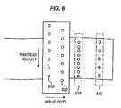
- FIG. 6 is a diagram illustrating an exemplary printhead being repositioned over a web of print media, and FIG. 6 helps to illustrate potential problems with moving a printhead too quickly.
- the printhead is made up of multiple rows of nozzles, 610 and 620. Each row is located at a different location with respect to the direction of travel of the web. After printing, the ink from the rows of nozzles should be evenly distributed, as shown by element 630.
- row 620 of the printhead may print at a different location than intended relative to row 610. Even though the output from the rows is intended to be evenly distributed, as shown by element 630, the output appears jittery as shown by element 640. In short, when the motion of the printhead is substantial and the printhead is printing while it is being repositioned, each row can mark a different lateral position on the web than intended. A speed limit for the printhead can help to address this problem.
- controller 420 can identify a resonant frequency of printing system 400.
- a resonant frequency of printing system 400 is a frequency of motion that amplifies the vibration that naturally occurs within printing system 400 during printing. Resonant vibrations at printing system 400 can cause damage to its components.
- controller 420 can take measures to keep from increasing resonant vibrations at printing system 400 when it moves one or more printheads 412 back and forth. To this end, controller 420 can apply a stopband filter to input from sensor 430, in order to stop from measuring (and therefore attempting to correct) vibrations of printing system 400 that occur at the resonant frequency. This can be desirable, as correcting for motions of the web at resonant frequencies can in some cases increase vibrations at printing system 400 and damage it. However, in some embodiments a stopband filter is not applied, meaning that corrections for vibrations at the natural frequency of the printing system can be applied.
- FIG. 7 is a block diagram 700 illustrating a further exemplary printing system that accounts for lateral shifts at a web of print media.
- the printing system includes two inkjet printers used to print incoming jobs.
- Each printer includes two printhead arrays, and each printhead array is used as a color plane to mark a different color of ink onto a web 720 of print media.
- the upstream printer 710 marks black and magenta ink onto web 720 print media, while the downstream printer (not shown) marks cyan and yellow ink onto web 720.
- web 720 While a job is being printed, web 720 travels through the printing system at a rate of eight linear feet per second, and the lateral position of web 720 fluctuates back and forth.
- the printing system corrects lateral deviations at web 720 that are between about five microns and several hundred microns, occurring at a rate of about 0.1 to 2 Hertz (Hz).
- the furthest upstream printhead array 711 here, the printhead array responsible for the black color plane
- the gutter mark is located in a margin of web 720, which will later be cut from web 720 before the print job is delivered to a customer.
- Mark 722 extends along web 720 in the direction of the flow for web 720, and marks a specific lateral location on printhead array 711. While mark 722 is shown as a solid line, it can be generated as any suitable visual indicator (e.g., single marks spaced out at defined intervals).
- printer 710 uses a camera 716 to detect a position of mark 722 on web 720.
- controller 714 analyzes a lateral distance between the mark and a reference location on printhead array 712, and drives linear actuator 717 to adjust the position of printhead array 712 so that by the time the mark reaches printhead array 712, printhead array 712 will be in the appropriate position.
- controller 714 moves printhead array 712 by some distance ⁇ to ensure that the magenta color plane is aligned with the black color plane (i.e., in order to account for the shift in web 720 as it travels between the color planes).
- Each of the color planes in the downstream printer (not shown) use similar systems to laterally align themselves to the first printhead array.
- each color plane may make one or more gutter marks for reference by the other color planes, or an independent system may apply a gutter mark, such as an ultraviolet or thermal gutter mark invisible to the naked eye.
- a laser thru-beam sensor is placed at printhead array 711 to measure an edge position of the web, and camera 716 is not used.
- the lateral edge position of the web at printhead array 711 is compared to a current lateral position of printhead array 712 to determine a lateral distance between the two.
- printhead 712 is moved (after a suitable time delay based on web speed) to a new position to eliminate/reduce the measured amount of lateral distance between the two.
- Embodiments disclosed herein can take the form of software, hardware, firmware, or various combinations thereof.
- software is used to direct a processing system of controller 420 to perform the various operations disclosed herein.
- FIG. 8 illustrates a processing system 800 operable to execute a computer readable medium embodying programmed instructions to perform desired functions in an exemplary embodiment.
- Processing system 800 is operable to perform the above operations by executing programmed instructions tangibly embodied on computer readable storage medium 812.
- embodiments of the invention can take the form of a computer program accessible via computer-readable medium 812 providing program code for use by a computer or any other instruction execution system.
- computer readable storage medium 812 can be anything that can contain or store the program for use by the computer.
- Computer readable storage medium 812 can be an electronic, magnetic, optical, electromagnetic, infrared, or semiconductor device. Examples of computer readable storage medium 812 include a solid state memory, a magnetic tape, a removable computer diskette, a random access memory (RAM), a read-only memory (ROM), a rigid magnetic disk, and an optical disk. Current examples of optical disks include compact disk - read only memory (CD-ROM), compact disk - read/write (CD-R/W), and DVD.
- CD-ROM compact disk - read only memory
- CD-R/W compact disk - read/write
- Processing system 800 being suitable for storing and/or executing the program code, includes at least one processor 802 coupled to program and data memory 804 through a system bus 850.
- Program and data memory 804 can include local memory employed during actual execution of the program code, bulk storage, and cache memories that provide temporary storage of at least some program code and/or data in order to reduce the number of times the code and/or data are retrieved from bulk storage during execution.
- I/O devices 806 can be coupled either directly or through intervening I/O controllers.
- Network adapter interfaces 808 may also be integrated with the system to enable processing system 800 to become coupled to other data processing systems or storage devices through intervening private or public networks. Modems, cable modems, TBM Channel attachments, SCSI, Fibre Channel, and Ethernet cards are just a few of the currently available types of network or host interface adapters.
- Display device interface 810 may be integrated with the system to interface to one or more display devices, such as printing systems and screens for presentation of data generated by processor 802.
Landscapes
- Engineering & Computer Science (AREA)
- Quality & Reliability (AREA)
- Ink Jet (AREA)
Abstract
Description
- The invention relates to the field of printing systems, and in particular, to alignment of printheads in continuous-forms printing systems.
- Entities with substantial printing demands typically use a production printer. A production printer is a high-speed printer used for volume printing (e.g., one hundred pages per minute or more). Production printers include continuous-forms printers that print on a web of print media stored on a large roll.
- A production printer typically includes a localized print controller that controls the overall operation of the printing system, and a print engine (sometimes referred to as an "imaging engine" or a "marking engine"). The print engine includes one or more printhead assemblies, with each assembly including a printhead controller and a printhead (or array of printheads). An individual printhead includes multiple (e.g., hundreds of) tiny nozzles that are operable to discharge ink as controlled by the printhead controller. A printhead array is formed from multiple printheads that are spaced in series across the width of the web of print media.
- While printing, the web is quickly passed underneath the nozzles, which discharge ink at intervals to form pixels on the web. In order to ensure that the web is consistently positioned underneath the nozzles, steering systems can be used to align the web laterally with respect to its direction of travel. For example, these steering systems can be calibrated when the printer is first installed. However, even when the web is aligned, fluctuations in the physical properties of the web itself (e.g., small micron-level variations along the edge of the web, lateral tension variation along the web, orientation of the fibers in the web, etc.) can cause the web to experience lateral shifts during printing. This means that printed output for a print job can appear to shift back and forth across the pages of a document. Even though the individual shifts can be small (e.g., on the order of microns), the shifts can reduce print quality. For example, when multiple printheads are used by a printer to form a mixed color pixel, a small fluctuation in web position can cause an upstream printhead to mark the correct physical location, while a downstream printhead marks the wrong physical location. This distorts the final color of the pixel in the printed job.
- Embodiments described herein adjust the lateral position of one or more printheads during printing in order to ensure that the printheads mark the correct positions along the width of a web of print media. These systems and methods can dynamically adjust themselves to account for fluctuations at the web that occur while a job is printing.
- One embodiment is a system for aligning printheads of a printing system. The system comprises a sensor and a controller. The sensor is able to detect changes in a lateral position of a web of print media traveling through a continuous-forms printing system, and the controller is able to adjust a lateral position of a printhead while the printing system is operating to compensate for the detected changes in web position.
- Other exemplary embodiments (e.g., methods and computer-readable media relating to the foregoing embodiments) may be described below.
- The invention is illustrated by way of example, and not by way of limitation in the figures of the accompanying drawings in which like reference numerals are used to refer to similar elements.
-
FIG. 1 illustrates an exemplary continuous-forms printing system. -
FIG. 2 illustrates how a web of print media can oscillate laterally within the printing system ofFIG. 1 during printing. -
FIG. 3 is a diagram illustrating exemplary problems resulting from lateral web oscillations in a printing system that uses multiple color planes. -
FIG. 4 is a block diagram illustrating a printing system that accounts for lateral shifts at a web of print media in an exemplary embodiment. -
FIG. 5 is a flowchart illustrating a method of accounting for lateral shifts at a web of print media in an exemplary embodiment. -
FIG. 6 is a diagram illustrating an exemplary printhead being repositioned over a web of print media. -
FIG. 7 is a block diagram illustrating a further exemplary printing system that accounts for lateral shifts at a web of print media. -
FIG. 8 illustrates a processing system operable to execute a computer readable medium embodying programmed instructions to perform desired functions in an exemplary embodiment. - The figures and the following description illustrate specific exemplary embodiments of the invention. It will thus be appreciated that those skilled in the art will be able to devise various arrangements that, although not explicitly described or shown herein, embody the principles of the invention and are included within the scope of the invention. Furthermore, any examples described herein are intended to aid in understanding the principles of the invention, and are to be construed as being without limitation to such specifically recited examples and conditions. As a result, the invention is not limited to the specific embodiments or examples described below, but by the claims and their equivalents.
-
FIG. 1 illustrates an exemplary continuous-forms printing system 100.Printing system 100 includesproduction printer 110, which is operable to apply ink onto aweb 120 of continuous-form print media (e.g., paper). As used herein, the word "ink" is used to refer to any suitable marking fluid (e.g., aqueous inks, oil-based paints, etc.).Printer 110 may comprise an inkjet printer that applies colored inks, such as Cyan (C), Magenta (M), Yellow (Y), and Key (K) black inks. One ormore rollers 130 position andtension web 120 as it travels throughprinting system 100. -
FIG. 2 illustrates how a web of print media can shift laterally within theexemplary printing system 100 ofFIG. 1 during printing. For example,FIG. 2 atelement 210 illustrates that rollers can impart lateral shifts to a web of print media. As used herein, a lateral shift is a positional change that is within the plane of the web and orthogonal to the direction of travel of the web (i.e., orthogonal to the length of the web, and parallel to the width of the web). - As shown in
element 210, before traveling through a roller the lateral position of the web (with respect to the web's direction of travel) is above the dashed reference line. After traveling through the roller, it is below the reference line. Furthermore, the degree of lateral shifting imparted byprinting system 100 itself can oscillate in amplitude and direction whileprinting system 100 is operating. In short, the very act of driving the web can cause the web to laterally oscillate back and forth. No static adjustments can compensate for these oscillating lateral shifts that occur during printing. -
FIG. 2 atelement 220 shows that the web itself can also contribute to lateral fluctuations. Element 220 shows that a web may have an uneven edge. For example, some webs of print media are initially cut with a blade. When a long cut is being made, the blade itself can oscillate laterally back and forth at a certain frequency by very small amounts (e.g., a few microns). This in turn imparts an uneven edge to the web. Since many printheads maintain the same absolute position while printing, the distance of printed marks relative to the edge of the paper will vary as the edge of the paper itself varies, which can reduce print quality. -
FIG. 3 is a diagram illustrating exemplary problems resulting from lateral web oscillations in a printing system that uses multiple color planes. In this case, eachprinthead 310 acts as a color plane for one of cyan, magenta, yellow, and key black. InFIG. 3 , eachprinthead 310 is aligned in the same position relative to its peers, as indicated byreference lines 320. When the printheads are aligned in this manner, they will all mark exactly the same lateral position with respect to each other. Unfortunately, because the position ofweb 120 fluctuates in between the printheads, ink marked by eachprinthead 310 actually shows up in a different lateral position atweb 120, as shown byelement 330. This color plane separation occurs even though each ofprintheads 310 is marking the exact same lateral position with respect to its peers. - To address these problems with printhead alignment,
FIG. 4 illustrates aprinting system 400 that accounts for lateral shifts at a web of print media in an exemplary embodiment.Printing system 400 comprises any system, component, or device operable to mark a web of print media.Printing system 400 has been enhanced to adjust the lateral position ofprinthead 412 with respect to the direction of travel of the web during printing. - In this embodiment,
printing system 400 includesprinter 410, which has one ormore printheads 412 used to mark ink ontoweb 120.Printing system 400 also includes a printhead positioning system, which is made up ofcontroller 420 andweb position sensor 430.Web position sensor 430 detects the lateral position of the web before it reachesprinthead 412, andcontroller 420 adjusts the lateral position ofprinthead 412 during printing to compensate for the changing position of the web during printing. -
Sensor 430 comprises any system, component, or device operable to detect positional shifts in the web. For example,sensor 430 can comprise a laser, pneumatic, photoelectric, ultrasonic, infrared, optical, or any other suitable type of sensing device. Sensor 340 is placed upstream ofprinthead 412 with respect to the direction of travel of the web during printing. In one embodiment, sensor 340 detects the location of a physical edge of the web, while in another embodiment, sensor 340 detects a position of the web based on marks made by an upstream printhead. -
Controller 420 comprises any system, component, or device operable to control the position ofprinthead 412, based on changes in lateral position detected bysensor 430. For example,controller 420 may direct a positioning device to physically moveprinthead 412 as shown by the arrows inFIG. 4 to account for detected changes.Controller 420 can be implemented, for example, as custom circuitry, as a processor executing programmed instructions stored in an associated program memory, or some combination thereof. - The positioning device can comprise a linear actuator, a movable printhead assembly that can reposition itself by driving itself along a fixed rail, or any other suitable system capable of moving
printhead 412. - Illustrative details of the operation of
printing system 400 will be discussed with regard toFIG. 5 . Assume, for this embodiment, thatprinter 410 has started printing, and that during printing the web is being driven underneathprinthead 412. Further, assume that the lateral position of the web is shifting slightly back and forth due to the web being driven. -
FIG. 5 is a flowchart illustrating a method of accounting for lateral shifts at a web of print media in an exemplary embodiment. The steps ofmethod 500 are described with reference toprinting system 400 ofFIG. 4 , but those skilled in the art will appreciate thatmethod 500 may be performed in other systems. The steps of the flowcharts described herein are not all inclusive and may include other steps not shown. The steps described herein may also be performed in an alternative order. - In
step 502,sensor 430 detects changes in the lateral position of the web traveling throughprinting system 400. These changes are reported tocontroller 420, which may analyze the detected changes before taking action. For example in oneembodiment controller 420 ignores variations that are below a certain threshold level (e.g., a micron). - In
step 504,controller 420 adjusts the lateral position ofprinthead 412 while printingsystem 400 is operating to compensate for the detected changes in the position of the web. In one embodiment,controller 420 directs a positioning device to moveprinthead 412 based on the detected changes. For example, ifcontroller 420 detects that the web has shifted to the upward with respect toFIG. 4 by fifty microns, then it may direct the positioning device to moveprinthead 412 upward by fifty microns to match the web shift.Controller 420 may additionally implement a positioning "lag time" based on the distance betweensensor 430 andprinthead 412 and the speed at which the web is currently traveling. For example, ifsensor 430 is positioned one and a half seconds upstream ofprinthead 412,controller 420 can implement a lag time to ensure thatprinthead 412 has moved to its new position after one and a half seconds (e.g., by implementing an input delay for an actuator driving printhead 412). -
Method 500 can repeat continuously during printing so that lateral shifts in the web are consistently identified and addressed. This allowsprinting system 400 to dynamically account for lateral movement at the web during printing, even when the web moves unpredictably. Better positioning of printheads with respect to the web ensures greater print quality, and in systems that use multiple colors of ink, it also helps to ensure that printed colors are accurately marked onto the print media. - In a further embodiment,
controller 420 may process input fromsensor 430 with a lowpass filter before attempting to correct shifts in the position of the web. A lowpass filter (in, for example, the 2 Hertz (Hz) range) can help to keepcontroller 420 from responding to high-frequency noise when repositioningprinthead 412. - In another embodiment,
controller 420 may identify an acceleration limit forprinthead 412 whenprinthead 412 is being repositioned.Controller 420 then keepsprinthead 412 from exceeding the defined limit. Ifprinthead 412 is accelerated too quickly when it is being moved, the original momentum ofprinthead 412 can cause it to overshoot its intended final location. This in turn can cause positioning errors atprinthead 412 whenprinthead 412 overshoots its target location. - In another embodiment,
controller 420 identifies a limit for a speed ofprinthead 412 whenprinthead 412 is being repositioned.Controller 420 then keepsprinthead 412 from exceeding the defined velocity limit.FIG. 6 is a diagram illustrating an exemplary printhead being repositioned over a web of print media, andFIG. 6 helps to illustrate potential problems with moving a printhead too quickly. InFIG. 6 , the printhead is made up of multiple rows of nozzles, 610 and 620. Each row is located at a different location with respect to the direction of travel of the web. After printing, the ink from the rows of nozzles should be evenly distributed, as shown byelement 630. However, if the entire printhead is moved too quickly laterally across the web,row 620 of the printhead may print at a different location than intended relative to row 610. Even though the output from the rows is intended to be evenly distributed, as shown byelement 630, the output appears jittery as shown byelement 640. In short, when the motion of the printhead is substantial and the printhead is printing while it is being repositioned, each row can mark a different lateral position on the web than intended. A speed limit for the printhead can help to address this problem. - In a further embodiment,
controller 420 can identify a resonant frequency ofprinting system 400. A resonant frequency ofprinting system 400 is a frequency of motion that amplifies the vibration that naturally occurs withinprinting system 400 during printing. Resonant vibrations atprinting system 400 can cause damage to its components. - Once
controller 420 determines the resonant frequencies of printing system 400 (e.g., by consulting values stored in memory),controller 420 can take measures to keep from increasing resonant vibrations atprinting system 400 when it moves one ormore printheads 412 back and forth. To this end,controller 420 can apply a stopband filter to input fromsensor 430, in order to stop from measuring (and therefore attempting to correct) vibrations ofprinting system 400 that occur at the resonant frequency. This can be desirable, as correcting for motions of the web at resonant frequencies can in some cases increase vibrations atprinting system 400 and damage it. However, in some embodiments a stopband filter is not applied, meaning that corrections for vibrations at the natural frequency of the printing system can be applied. - In the following examples, additional processes, systems, and methods are described in the context of a printing system that adjusts printhead position with respect to a web of print media during printing.
-
FIG. 7 is a block diagram 700 illustrating a further exemplary printing system that accounts for lateral shifts at a web of print media. In this embodiment, the printing system includes two inkjet printers used to print incoming jobs. Each printer includes two printhead arrays, and each printhead array is used as a color plane to mark a different color of ink onto aweb 720 of print media. Theupstream printer 710 marks black and magenta ink ontoweb 720 print media, while the downstream printer (not shown) marks cyan and yellow ink ontoweb 720. - While a job is being printed,
web 720 travels through the printing system at a rate of eight linear feet per second, and the lateral position ofweb 720 fluctuates back and forth. The printing system corrects lateral deviations atweb 720 that are between about five microns and several hundred microns, occurring at a rate of about 0.1 to 2 Hertz (Hz). In order to calibrate the corrections made by the various printhead arrays, the furthest upstream printhead array 711 (here, the printhead array responsible for the black color plane) makes agutter mark 722 ontoweb 120. In this example the gutter mark is located in a margin ofweb 720, which will later be cut fromweb 720 before the print job is delivered to a customer.Mark 722 extends alongweb 720 in the direction of the flow forweb 720, and marks a specific lateral location onprinthead array 711. Whilemark 722 is shown as a solid line, it can be generated as any suitable visual indicator (e.g., single marks spaced out at defined intervals). - To account for the positional shifts of
upstream printhead array 711 with respect toweb 720,printer 710 uses acamera 716 to detect a position ofmark 722 onweb 720. When the lateral position ofmark 722 changes,controller 714 analyzes a lateral distance between the mark and a reference location onprinthead array 712, and driveslinear actuator 717 to adjust the position ofprinthead array 712 so that by the time the mark reachesprinthead array 712,printhead array 712 will be in the appropriate position. In effect,controller 714moves printhead array 712 by some distance Δ to ensure that the magenta color plane is aligned with the black color plane (i.e., in order to account for the shift inweb 720 as it travels between the color planes). Each of the color planes in the downstream printer (not shown) use similar systems to laterally align themselves to the first printhead array. - In further embodiments, each color plane may make one or more gutter marks for reference by the other color planes, or an independent system may apply a gutter mark, such as an ultraviolet or thermal gutter mark invisible to the naked eye.
- In another example, a laser thru-beam sensor is placed at
printhead array 711 to measure an edge position of the web, andcamera 716 is not used. In this example, the lateral edge position of the web atprinthead array 711 is compared to a current lateral position ofprinthead array 712 to determine a lateral distance between the two. Then,printhead 712 is moved (after a suitable time delay based on web speed) to a new position to eliminate/reduce the measured amount of lateral distance between the two. - Embodiments disclosed herein can take the form of software, hardware, firmware, or various combinations thereof. In one particular embodiment, software is used to direct a processing system of
controller 420 to perform the various operations disclosed herein.FIG. 8 illustrates aprocessing system 800 operable to execute a computer readable medium embodying programmed instructions to perform desired functions in an exemplary embodiment.Processing system 800 is operable to perform the above operations by executing programmed instructions tangibly embodied on computerreadable storage medium 812. In this regard, embodiments of the invention can take the form of a computer program accessible via computer-readable medium 812 providing program code for use by a computer or any other instruction execution system. For the purposes of this description, computerreadable storage medium 812 can be anything that can contain or store the program for use by the computer. - Computer
readable storage medium 812 can be an electronic, magnetic, optical, electromagnetic, infrared, or semiconductor device. Examples of computerreadable storage medium 812 include a solid state memory, a magnetic tape, a removable computer diskette, a random access memory (RAM), a read-only memory (ROM), a rigid magnetic disk, and an optical disk. Current examples of optical disks include compact disk - read only memory (CD-ROM), compact disk - read/write (CD-R/W), and DVD. -
Processing system 800, being suitable for storing and/or executing the program code, includes at least oneprocessor 802 coupled to program anddata memory 804 through asystem bus 850. Program anddata memory 804 can include local memory employed during actual execution of the program code, bulk storage, and cache memories that provide temporary storage of at least some program code and/or data in order to reduce the number of times the code and/or data are retrieved from bulk storage during execution. - Input/output or I/O devices 806 (including but not limited to keyboards, displays, pointing devices, etc.) can be coupled either directly or through intervening I/O controllers. Network adapter interfaces 808 may also be integrated with the system to enable
processing system 800 to become coupled to other data processing systems or storage devices through intervening private or public networks. Modems, cable modems, TBM Channel attachments, SCSI, Fibre Channel, and Ethernet cards are just a few of the currently available types of network or host interface adapters.Display device interface 810 may be integrated with the system to interface to one or more display devices, such as printing systems and screens for presentation of data generated byprocessor 802. - Although specific embodiments were described herein, the scope of the invention is not limited to those specific embodiments. The scope of the invention is defined by the following claims and any equivalents thereof.
- The present application is based on and claims the benefit of priority of
US Application No. 13/933, 582 filed on July 2, 2013
Claims (15)
- A system (400) comprising:a sensor (430) operable to detect changes in a lateral position of a web of print media traveling through a continuous-forms printing system; anda controller (420) operable to adjust a lateral position of a printhead while the printing system is operating to compensate for the detected changes in web position.
- The system of claim 1, wherein:the controller is further operable to adjust the lateral position of the printhead based on input from the sensor indicating a location of an edge of the web.
- The system of claim 1, wherein:the controller is further operable to adjust the lateral position of the printhead based on input from the sensor indicating a location of marks made on the web by an upstream printhead array.
- The system of claim 1, further comprising:a positioning device connected to the printhead; whereinthe controller is further operable to direct the positioning device to adjust the position of the printhead.
- The system of claim 1, wherein:the controller is further operable to limit a velocity at which the position of the printhead is adjusted.
- The system of claim 1, wherein:the controller is further operable to limit an acceleration experienced by the printhead when adjusting the position of the printhead.
- The system of claim 1, wherein:the sensor detects the changes in web position at an upstream color plane, andthe controller is further operable to determine a lateral distance between a detected position of the web at the upstream color plane and the printhead, and to move the printhead to reduce the lateral distance.
- The system of claim 1, wherein:the controller is further operable to identify a resonant frequency of the printing system, and to apply a stop band filter to filter out detected changes occurring at the resonant frequency.
- A method comprising the steps of:detecting changes in a lateral position of a web of print media traveling through a continuous-forms printing system; andadjusting a lateral position of a printhead of the printing system while the printing system is operating to compensate for the detected changes in web position.
- The method of claim 9, further comprising the step of:adjusting the lateral position of the printhead based on input from a sensor indicating a location of an edge of the web.
- The method of claim 9, further comprising the step of:adjusting the lateral position of the printhead based on input from the sensor indicating a location of marks made on the web by an upstream printhead.
- The method of claim 9, further comprising the step of:directing a positioning device to adjust the position of the printhead.
- A non-transitory computer readable medium embodying programmed instructions which, when executed by a processor, are operable for performing the steps of claim 9.
- A computer program comprising computer program code means which, when executed by a processor, are operable for performing the steps of claim 9.
- The computer program comprising computer program code means which, when executed by a processor, are operable for performing the steps of claim 10.
Applications Claiming Priority (1)
| Application Number | Priority Date | Filing Date | Title |
|---|---|---|---|
| US13/933,582 US9028027B2 (en) | 2013-07-02 | 2013-07-02 | Alignment of printheads in printing systems |
Publications (2)
| Publication Number | Publication Date |
|---|---|
| EP2857208A1 true EP2857208A1 (en) | 2015-04-08 |
| EP2857208B1 EP2857208B1 (en) | 2019-10-30 |
Family
ID=50819526
Family Applications (1)
| Application Number | Title | Priority Date | Filing Date |
|---|---|---|---|
| EP14164665.3A Active EP2857208B1 (en) | 2013-07-02 | 2014-04-15 | Alignment of printheads in printing systems |
Country Status (3)
| Country | Link |
|---|---|
| US (1) | US9028027B2 (en) |
| EP (1) | EP2857208B1 (en) |
| JP (2) | JP6879654B2 (en) |
Cited By (2)
| Publication number | Priority date | Publication date | Assignee | Title |
|---|---|---|---|---|
| EP3034308A3 (en) * | 2014-10-30 | 2016-08-24 | Ricoh Company, Ltd. | Image forming apparatus |
| CN110271276A (en) * | 2018-03-14 | 2019-09-24 | 西门子股份公司 | The method and apparatus and printing machine in the printing position for calibrating printer structure |
Families Citing this family (42)
| Publication number | Priority date | Publication date | Assignee | Title |
|---|---|---|---|---|
| US9319916B2 (en) | 2013-03-15 | 2016-04-19 | Isco International, Llc | Method and appartus for signal interference processing |
| JP6350211B2 (en) | 2014-10-27 | 2018-07-04 | 株式会社リコー | Recording position control apparatus and abnormality detection method thereof |
| JP6418491B2 (en) * | 2014-10-29 | 2018-11-07 | 株式会社リコー | Recording unit discharge position adjusting apparatus and image forming apparatus |
| US9440431B2 (en) | 2014-11-19 | 2016-09-13 | Ricoh Company, Ltd. | Inkjet recording apparatus |
| US9315055B1 (en) | 2015-02-26 | 2016-04-19 | Ricoh Company, Ltd. | Printhead position control |
| JP6528945B2 (en) * | 2015-05-28 | 2019-06-12 | セイコーエプソン株式会社 | Liquid discharge device |
| JP6528946B2 (en) * | 2015-05-28 | 2019-06-12 | セイコーエプソン株式会社 | Liquid discharge device |
| EP3271186A4 (en) * | 2015-07-09 | 2018-12-19 | Hewlett-Packard Development Company, L.P. | Printer configuration |
| US9682576B2 (en) * | 2015-09-03 | 2017-06-20 | Océ-Technologies B.V. | Printing assembly |
| CN106559887B (en) * | 2015-09-29 | 2021-12-31 | 华为技术有限公司 | Method for configuring resources and network equipment |
| US9844956B2 (en) | 2015-10-07 | 2017-12-19 | Intermec Technologies Corporation | Print position correction |
| US9744759B2 (en) | 2015-10-20 | 2017-08-29 | Ricoh Company, Ltd. | Position correction apparatus, liquid ejection apparatus, and method for correcting position |
| JP2017077726A (en) * | 2015-10-20 | 2017-04-27 | 株式会社リコー | Position correcting device, liquid emitting device, and position correcting method |
| CN107053866B (en) * | 2015-12-14 | 2020-06-12 | 株式会社理光 | Liquid ejection equipment, liquid ejection system and liquid ejection method |
| JP7005893B2 (en) * | 2015-12-14 | 2022-01-24 | 株式会社リコー | Liquid discharge device, liquid discharge system and liquid discharge method |
| JP7047247B2 (en) * | 2015-12-14 | 2022-04-05 | 株式会社リコー | Liquid discharge device, liquid discharge system and liquid discharge method |
| US10207494B2 (en) | 2015-12-25 | 2019-02-19 | Ricoh Company, Ltd. | Liquid ejection apparatus, liquid ejection system, and liquid ejection method |
| EP3216614B1 (en) * | 2016-03-11 | 2019-01-30 | Ricoh Company, Ltd. | Liquid ejection device, liquid ejection system, and liquid ejection method |
| JP6801479B2 (en) * | 2016-03-11 | 2020-12-16 | 株式会社リコー | Liquid discharge device, liquid discharge system and liquid discharge method |
| US10040278B2 (en) | 2016-03-15 | 2018-08-07 | Ricoh Company, Ltd. | Conveyed object detection apparatus, conveyance apparatus, and conveyed object detection method |
| US10814622B2 (en) | 2016-03-17 | 2020-10-27 | Ricoh Company, Ltd. | Liquid ejection apparatus, liquid ejection system, and liquid ejection method |
| JP6740706B2 (en) * | 2016-05-20 | 2020-08-19 | 株式会社リコー | Image forming apparatus and head position adjusting method |
| EP3248921B1 (en) | 2016-05-24 | 2018-12-12 | OCE Holding B.V. | Web medium orientation detection |
| US10166786B2 (en) | 2016-06-07 | 2019-01-01 | Ricoh Company, Ltd. | Device including movable head and head control method |
| US10682870B2 (en) * | 2016-06-09 | 2020-06-16 | Ricoh Company, Ltd. | Conveyed object detector, conveyance device, device including movable head, conveyed object detecting method, and non-transitory recording medium storing program of same |
| JP7039873B2 (en) * | 2016-07-25 | 2022-03-23 | 株式会社リコー | Liquid discharge device, liquid discharge method and liquid discharge system |
| US10336063B2 (en) | 2016-07-25 | 2019-07-02 | Ricoh Company, Ltd. | Liquid discharge apparatus, liquid discharge system, and liquid discharge method |
| EP3275675B1 (en) | 2016-07-26 | 2022-02-16 | Ricoh Company, Ltd. | Apparatus to perform operation on conveyed object |
| US10632770B2 (en) | 2017-02-17 | 2020-04-28 | Ricoh Company, Ltd. | Conveyance device, conveyance system, and head control method |
| US10334130B2 (en) | 2017-03-15 | 2019-06-25 | Ricoh Company, Ltd. | Image forming apparatus, image forming system, and position adjustment method |
| US10639916B2 (en) | 2017-03-21 | 2020-05-05 | Ricoh Company, Ltd. | Conveyance device, conveyance system, and head unit position adjusting method |
| US10744756B2 (en) | 2017-03-21 | 2020-08-18 | Ricoh Company, Ltd. | Conveyance device, conveyance system, and head unit control method |
| WO2018231190A1 (en) | 2017-06-12 | 2018-12-20 | Hewlett-Packard Development Company, L.P. | Conveyor belt sensors |
| WO2018230576A1 (en) | 2017-06-14 | 2018-12-20 | Ricoh Company, Ltd. | Transfer apparatus, liquid ejection apparatus, reading apparatus, image forming apparatus, control method of the transfer apparatus |
| US10675899B2 (en) | 2017-06-14 | 2020-06-09 | Ricoh Company, Ltd. | Detector, image forming apparatus, reading apparatus, and adjustment method |
| JP7073928B2 (en) * | 2017-06-14 | 2022-05-24 | 株式会社リコー | Conveyor device, liquid discharge device, reading device, image forming device, control method of the transfer device |
| JP7392267B2 (en) | 2019-03-14 | 2023-12-06 | 株式会社リコー | Conveyance device and image forming device |
| US11420453B2 (en) | 2019-03-18 | 2022-08-23 | Ricoh Company, Ltd. | Conveyance device and liquid discharge apparatus |
| US11858277B2 (en) | 2019-04-29 | 2024-01-02 | Hewlett-Packard Development Company, L.P. | Rotating housing with sensor |
| EP4004620B1 (en) | 2019-07-23 | 2025-11-26 | Corning Incorporated | Methods for accurate high-speed marking of optical fibers |
| JP2021037728A (en) | 2019-09-05 | 2021-03-11 | 富士ゼロックス株式会社 | Image forming device |
| JP7508688B2 (en) * | 2020-07-13 | 2024-07-01 | グアンジョウ キングタウ マシーナリー アンド エレクトロニクス エキップメント カンパニー リミテッド | Method and system for printing on tilted print media with a print head - Patents.com |
Citations (6)
| Publication number | Priority date | Publication date | Assignee | Title |
|---|---|---|---|---|
| US20020126169A1 (en) * | 2001-03-08 | 2002-09-12 | Wyngaert Hilbrand Vanden | Ink-jet printer equipped for aligning the printheads |
| US20100150632A1 (en) * | 2008-12-16 | 2010-06-17 | Canon Kabushiki Kaisha | Recording apparatus and recording method |
| US20100243697A1 (en) * | 2009-03-26 | 2010-09-30 | Hiroyuki Aoki | Medium conveying apparatus and image forming apparatus |
| US20110273502A1 (en) * | 2010-05-04 | 2011-11-10 | Xerox Corporation | Method And System To Compensate For Process Direction Misalignment Of Printheads In A Continuous Web Inkjet Printer |
| US20110298849A1 (en) * | 2010-06-03 | 2011-12-08 | Canon Kabushiki Kaisha | Inkjet printing apparatus |
| US20120223996A1 (en) * | 2011-03-02 | 2012-09-06 | Ernst Larry M | Print data compensation for variations in paper position within a printing system |
Family Cites Families (18)
| Publication number | Priority date | Publication date | Assignee | Title |
|---|---|---|---|---|
| US4572417A (en) | 1984-04-06 | 1986-02-25 | Eastman Kodak Company | Web tracking apparatus |
| JPS62198477A (en) * | 1986-02-26 | 1987-09-02 | Olympus Optical Co Ltd | Multicolor image-forming device |
| JP2690075B2 (en) * | 1986-08-21 | 1997-12-10 | 松下電送 株式会社 | Color image recording device |
| JPH11295037A (en) * | 1998-04-14 | 1999-10-29 | Minolta Co Ltd | Picture image forming apparatus |
| US6549225B2 (en) | 2001-02-28 | 2003-04-15 | Lexmark International, Inc. | Method of margin alignment and plane-to-plane registration in a tandem color electrophotographic machine |
| JP2003182896A (en) | 2001-12-20 | 2003-07-03 | Hitachi Printing Solutions Ltd | Printing apparatus having paper traveling position detecting device |
| US8075080B2 (en) | 2005-04-25 | 2011-12-13 | Ulvac, Inc. | Camera-based automatic nozzle and substrate alignment system |
| JP2010137489A (en) * | 2008-12-15 | 2010-06-24 | Seiko Epson Corp | Recording position correcting device, method for controlling recording position correction device, and recording apparatus |
| JP2010179583A (en) * | 2009-02-06 | 2010-08-19 | Seiko Epson Corp | Head unit position adjusting method and recording device |
| US7798587B2 (en) | 2009-02-17 | 2010-09-21 | Xerox Corporation | System and method for cross-process control of continuous web printing system |
| JP4793666B2 (en) * | 2009-03-27 | 2011-10-12 | ブラザー工業株式会社 | Image forming apparatus |
| US8075086B2 (en) * | 2009-07-31 | 2011-12-13 | Xerox Corporation | Paper skew detection system |
| DE102009039444A1 (en) * | 2009-08-31 | 2011-03-03 | Eastman Kodak Co. | Printing device and method for printing on a printing substrate |
| JP2011189602A (en) * | 2010-03-15 | 2011-09-29 | Seiko Epson Corp | Position correction apparatus and recording apparatus |
| US8270024B2 (en) | 2010-03-23 | 2012-09-18 | Lexmark International, Inc. | Apparatus and method for printing within a print zone on the surface of a skewed object moving in a given direction of travel |
| EP2563700A1 (en) | 2010-04-26 | 2013-03-06 | Metso Paper, Inc. | Method for controlling a tension profile of a web and web tension profile control apparatus |
| US8419144B2 (en) | 2010-05-11 | 2013-04-16 | Xerox Corporation | Media handling device for a printer |
| US8662623B2 (en) | 2011-08-25 | 2014-03-04 | Eastman Kodak Company | Printing registered patterns on multiple media sides |
-
2013
- 2013-07-02 US US13/933,582 patent/US9028027B2/en active Active
-
2014
- 2014-04-15 EP EP14164665.3A patent/EP2857208B1/en active Active
- 2014-06-30 JP JP2014134393A patent/JP6879654B2/en active Active
-
2018
- 2018-11-14 JP JP2018213406A patent/JP2019043142A/en active Pending
Patent Citations (6)
| Publication number | Priority date | Publication date | Assignee | Title |
|---|---|---|---|---|
| US20020126169A1 (en) * | 2001-03-08 | 2002-09-12 | Wyngaert Hilbrand Vanden | Ink-jet printer equipped for aligning the printheads |
| US20100150632A1 (en) * | 2008-12-16 | 2010-06-17 | Canon Kabushiki Kaisha | Recording apparatus and recording method |
| US20100243697A1 (en) * | 2009-03-26 | 2010-09-30 | Hiroyuki Aoki | Medium conveying apparatus and image forming apparatus |
| US20110273502A1 (en) * | 2010-05-04 | 2011-11-10 | Xerox Corporation | Method And System To Compensate For Process Direction Misalignment Of Printheads In A Continuous Web Inkjet Printer |
| US20110298849A1 (en) * | 2010-06-03 | 2011-12-08 | Canon Kabushiki Kaisha | Inkjet printing apparatus |
| US20120223996A1 (en) * | 2011-03-02 | 2012-09-06 | Ernst Larry M | Print data compensation for variations in paper position within a printing system |
Cited By (3)
| Publication number | Priority date | Publication date | Assignee | Title |
|---|---|---|---|---|
| EP3034308A3 (en) * | 2014-10-30 | 2016-08-24 | Ricoh Company, Ltd. | Image forming apparatus |
| CN110271276A (en) * | 2018-03-14 | 2019-09-24 | 西门子股份公司 | The method and apparatus and printing machine in the printing position for calibrating printer structure |
| CN110271276B (en) * | 2018-03-14 | 2021-07-27 | 西门子股份公司 | Method and apparatus for correcting printing position of a printing mechanism and printing press |
Also Published As
| Publication number | Publication date |
|---|---|
| JP6879654B2 (en) | 2021-06-02 |
| EP2857208B1 (en) | 2019-10-30 |
| JP2019043142A (en) | 2019-03-22 |
| JP2015013476A (en) | 2015-01-22 |
| US9028027B2 (en) | 2015-05-12 |
| US20150009262A1 (en) | 2015-01-08 |
Similar Documents
| Publication | Publication Date | Title |
|---|---|---|
| US9028027B2 (en) | Alignment of printheads in printing systems | |
| EP3020555B1 (en) | Alignment of printheads in printing systems | |
| US9186885B2 (en) | Alignment of printheads in printing systems | |
| JP6390211B2 (en) | Frequency-based web steering in printing systems | |
| JP6417858B2 (en) | Recording apparatus and recording apparatus control method | |
| US8783810B2 (en) | Dot formation positioning device, recording method, setting method, and recording program | |
| EP3248921B1 (en) | Web medium orientation detection | |
| US8573727B2 (en) | Inkjet printing apparatus and carriage control method for controlling carriage speed | |
| EP2868606B1 (en) | Web steering frames that include an independently adjustable roller | |
| EP3061614B1 (en) | Printhead position control | |
| JP2017517408A (en) | Flatbed printer assembly | |
| US9283752B2 (en) | Method for printing contiguous swaths | |
| EP3202583B1 (en) | Vacuum level calibration for a web-based printer | |
| EP2878558B1 (en) | Targeted heating of substrate | |
| US9028036B1 (en) | Edge-justified printing with a crowned roller | |
| CN116096583A (en) | Determining Printhead Alignment | |
| JP2015217525A (en) | Method for setting droplet discharge condition, droplet discharge method, and droplet discharge device | |
| JP2008012891A (en) | Automatic cash register adjustment |
Legal Events
| Date | Code | Title | Description |
|---|---|---|---|
| PUAI | Public reference made under article 153(3) epc to a published international application that has entered the european phase |
Free format text: ORIGINAL CODE: 0009012 |
|
| 17P | Request for examination filed |
Effective date: 20140415 |
|
| AK | Designated contracting states |
Kind code of ref document: A1 Designated state(s): AL AT BE BG CH CY CZ DE DK EE ES FI FR GB GR HR HU IE IS IT LI LT LU LV MC MK MT NL NO PL PT RO RS SE SI SK SM TR |
|
| AX | Request for extension of the european patent |
Extension state: BA ME |
|
| STAA | Information on the status of an ep patent application or granted ep patent |
Free format text: STATUS: EXAMINATION IS IN PROGRESS |
|
| 17Q | First examination report despatched |
Effective date: 20181017 |
|
| REG | Reference to a national code |
Ref country code: DE Ref legal event code: R079 Ref document number: 602014055837 Country of ref document: DE Free format text: PREVIOUS MAIN CLASS: B41J0002210000 Ipc: B41J0015040000 |
|
| GRAP | Despatch of communication of intention to grant a patent |
Free format text: ORIGINAL CODE: EPIDOSNIGR1 |
|
| STAA | Information on the status of an ep patent application or granted ep patent |
Free format text: STATUS: GRANT OF PATENT IS INTENDED |
|
| RIC1 | Information provided on ipc code assigned before grant |
Ipc: B41J 25/00 20060101ALI20190515BHEP Ipc: B41J 11/46 20060101ALI20190515BHEP Ipc: B41J 2/21 20060101ALI20190515BHEP Ipc: B41J 11/00 20060101ALI20190515BHEP Ipc: B41J 15/04 20060101AFI20190515BHEP |
|
| INTG | Intention to grant announced |
Effective date: 20190612 |
|
| GRAS | Grant fee paid |
Free format text: ORIGINAL CODE: EPIDOSNIGR3 |
|
| GRAA | (expected) grant |
Free format text: ORIGINAL CODE: 0009210 |
|
| STAA | Information on the status of an ep patent application or granted ep patent |
Free format text: STATUS: THE PATENT HAS BEEN GRANTED |
|
| AK | Designated contracting states |
Kind code of ref document: B1 Designated state(s): AL AT BE BG CH CY CZ DE DK EE ES FI FR GB GR HR HU IE IS IT LI LT LU LV MC MK MT NL NO PL PT RO RS SE SI SK SM TR |
|
| REG | Reference to a national code |
Ref country code: GB Ref legal event code: FG4D |
|
| REG | Reference to a national code |
Ref country code: CH Ref legal event code: EP |
|
| REG | Reference to a national code |
Ref country code: AT Ref legal event code: REF Ref document number: 1195713 Country of ref document: AT Kind code of ref document: T Effective date: 20191115 |
|
| REG | Reference to a national code |
Ref country code: DE Ref legal event code: R096 Ref document number: 602014055837 Country of ref document: DE |
|
| REG | Reference to a national code |
Ref country code: IE Ref legal event code: FG4D |
|
| REG | Reference to a national code |
Ref country code: NL Ref legal event code: FP |
|
| REG | Reference to a national code |
Ref country code: LT Ref legal event code: MG4D |
|
| PG25 | Lapsed in a contracting state [announced via postgrant information from national office to epo] |
Ref country code: BG Free format text: LAPSE BECAUSE OF FAILURE TO SUBMIT A TRANSLATION OF THE DESCRIPTION OR TO PAY THE FEE WITHIN THE PRESCRIBED TIME-LIMIT Effective date: 20200130 Ref country code: FI Free format text: LAPSE BECAUSE OF FAILURE TO SUBMIT A TRANSLATION OF THE DESCRIPTION OR TO PAY THE FEE WITHIN THE PRESCRIBED TIME-LIMIT Effective date: 20191030 Ref country code: GR Free format text: LAPSE BECAUSE OF FAILURE TO SUBMIT A TRANSLATION OF THE DESCRIPTION OR TO PAY THE FEE WITHIN THE PRESCRIBED TIME-LIMIT Effective date: 20200131 Ref country code: NO Free format text: LAPSE BECAUSE OF FAILURE TO SUBMIT A TRANSLATION OF THE DESCRIPTION OR TO PAY THE FEE WITHIN THE PRESCRIBED TIME-LIMIT Effective date: 20200130 Ref country code: PL Free format text: LAPSE BECAUSE OF FAILURE TO SUBMIT A TRANSLATION OF THE DESCRIPTION OR TO PAY THE FEE WITHIN THE PRESCRIBED TIME-LIMIT Effective date: 20191030 Ref country code: LV Free format text: LAPSE BECAUSE OF FAILURE TO SUBMIT A TRANSLATION OF THE DESCRIPTION OR TO PAY THE FEE WITHIN THE PRESCRIBED TIME-LIMIT Effective date: 20191030 Ref country code: SE Free format text: LAPSE BECAUSE OF FAILURE TO SUBMIT A TRANSLATION OF THE DESCRIPTION OR TO PAY THE FEE WITHIN THE PRESCRIBED TIME-LIMIT Effective date: 20191030 Ref country code: ES Free format text: LAPSE BECAUSE OF FAILURE TO SUBMIT A TRANSLATION OF THE DESCRIPTION OR TO PAY THE FEE WITHIN THE PRESCRIBED TIME-LIMIT Effective date: 20191030 Ref country code: LT Free format text: LAPSE BECAUSE OF FAILURE TO SUBMIT A TRANSLATION OF THE DESCRIPTION OR TO PAY THE FEE WITHIN THE PRESCRIBED TIME-LIMIT Effective date: 20191030 Ref country code: PT Free format text: LAPSE BECAUSE OF FAILURE TO SUBMIT A TRANSLATION OF THE DESCRIPTION OR TO PAY THE FEE WITHIN THE PRESCRIBED TIME-LIMIT Effective date: 20200302 |
|
| PG25 | Lapsed in a contracting state [announced via postgrant information from national office to epo] |
Ref country code: HR Free format text: LAPSE BECAUSE OF FAILURE TO SUBMIT A TRANSLATION OF THE DESCRIPTION OR TO PAY THE FEE WITHIN THE PRESCRIBED TIME-LIMIT Effective date: 20191030 Ref country code: RS Free format text: LAPSE BECAUSE OF FAILURE TO SUBMIT A TRANSLATION OF THE DESCRIPTION OR TO PAY THE FEE WITHIN THE PRESCRIBED TIME-LIMIT Effective date: 20191030 Ref country code: IS Free format text: LAPSE BECAUSE OF FAILURE TO SUBMIT A TRANSLATION OF THE DESCRIPTION OR TO PAY THE FEE WITHIN THE PRESCRIBED TIME-LIMIT Effective date: 20200229 |
|
| PG25 | Lapsed in a contracting state [announced via postgrant information from national office to epo] |
Ref country code: AL Free format text: LAPSE BECAUSE OF FAILURE TO SUBMIT A TRANSLATION OF THE DESCRIPTION OR TO PAY THE FEE WITHIN THE PRESCRIBED TIME-LIMIT Effective date: 20191030 |
|
| PG25 | Lapsed in a contracting state [announced via postgrant information from national office to epo] |
Ref country code: DK Free format text: LAPSE BECAUSE OF FAILURE TO SUBMIT A TRANSLATION OF THE DESCRIPTION OR TO PAY THE FEE WITHIN THE PRESCRIBED TIME-LIMIT Effective date: 20191030 Ref country code: EE Free format text: LAPSE BECAUSE OF FAILURE TO SUBMIT A TRANSLATION OF THE DESCRIPTION OR TO PAY THE FEE WITHIN THE PRESCRIBED TIME-LIMIT Effective date: 20191030 Ref country code: RO Free format text: LAPSE BECAUSE OF FAILURE TO SUBMIT A TRANSLATION OF THE DESCRIPTION OR TO PAY THE FEE WITHIN THE PRESCRIBED TIME-LIMIT Effective date: 20191030 Ref country code: CZ Free format text: LAPSE BECAUSE OF FAILURE TO SUBMIT A TRANSLATION OF THE DESCRIPTION OR TO PAY THE FEE WITHIN THE PRESCRIBED TIME-LIMIT Effective date: 20191030 |
|
| REG | Reference to a national code |
Ref country code: DE Ref legal event code: R097 Ref document number: 602014055837 Country of ref document: DE |
|
| REG | Reference to a national code |
Ref country code: AT Ref legal event code: MK05 Ref document number: 1195713 Country of ref document: AT Kind code of ref document: T Effective date: 20191030 |
|
| PG25 | Lapsed in a contracting state [announced via postgrant information from national office to epo] |
Ref country code: IT Free format text: LAPSE BECAUSE OF FAILURE TO SUBMIT A TRANSLATION OF THE DESCRIPTION OR TO PAY THE FEE WITHIN THE PRESCRIBED TIME-LIMIT Effective date: 20191030 Ref country code: SM Free format text: LAPSE BECAUSE OF FAILURE TO SUBMIT A TRANSLATION OF THE DESCRIPTION OR TO PAY THE FEE WITHIN THE PRESCRIBED TIME-LIMIT Effective date: 20191030 Ref country code: SK Free format text: LAPSE BECAUSE OF FAILURE TO SUBMIT A TRANSLATION OF THE DESCRIPTION OR TO PAY THE FEE WITHIN THE PRESCRIBED TIME-LIMIT Effective date: 20191030 |
|
| PLBE | No opposition filed within time limit |
Free format text: ORIGINAL CODE: 0009261 |
|
| STAA | Information on the status of an ep patent application or granted ep patent |
Free format text: STATUS: NO OPPOSITION FILED WITHIN TIME LIMIT |
|
| 26N | No opposition filed |
Effective date: 20200731 |
|
| PG25 | Lapsed in a contracting state [announced via postgrant information from national office to epo] |
Ref country code: AT Free format text: LAPSE BECAUSE OF FAILURE TO SUBMIT A TRANSLATION OF THE DESCRIPTION OR TO PAY THE FEE WITHIN THE PRESCRIBED TIME-LIMIT Effective date: 20191030 Ref country code: MC Free format text: LAPSE BECAUSE OF FAILURE TO SUBMIT A TRANSLATION OF THE DESCRIPTION OR TO PAY THE FEE WITHIN THE PRESCRIBED TIME-LIMIT Effective date: 20191030 Ref country code: SI Free format text: LAPSE BECAUSE OF FAILURE TO SUBMIT A TRANSLATION OF THE DESCRIPTION OR TO PAY THE FEE WITHIN THE PRESCRIBED TIME-LIMIT Effective date: 20191030 |
|
| REG | Reference to a national code |
Ref country code: CH Ref legal event code: PL |
|
| PG25 | Lapsed in a contracting state [announced via postgrant information from national office to epo] |
Ref country code: LU Free format text: LAPSE BECAUSE OF NON-PAYMENT OF DUE FEES Effective date: 20200415 Ref country code: LI Free format text: LAPSE BECAUSE OF NON-PAYMENT OF DUE FEES Effective date: 20200430 Ref country code: CH Free format text: LAPSE BECAUSE OF NON-PAYMENT OF DUE FEES Effective date: 20200430 |
|
| REG | Reference to a national code |
Ref country code: BE Ref legal event code: MM Effective date: 20200430 |
|
| PG25 | Lapsed in a contracting state [announced via postgrant information from national office to epo] |
Ref country code: BE Free format text: LAPSE BECAUSE OF NON-PAYMENT OF DUE FEES Effective date: 20200430 |
|
| PG25 | Lapsed in a contracting state [announced via postgrant information from national office to epo] |
Ref country code: IE Free format text: LAPSE BECAUSE OF NON-PAYMENT OF DUE FEES Effective date: 20200415 |
|
| PG25 | Lapsed in a contracting state [announced via postgrant information from national office to epo] |
Ref country code: TR Free format text: LAPSE BECAUSE OF FAILURE TO SUBMIT A TRANSLATION OF THE DESCRIPTION OR TO PAY THE FEE WITHIN THE PRESCRIBED TIME-LIMIT Effective date: 20191030 Ref country code: MT Free format text: LAPSE BECAUSE OF FAILURE TO SUBMIT A TRANSLATION OF THE DESCRIPTION OR TO PAY THE FEE WITHIN THE PRESCRIBED TIME-LIMIT Effective date: 20191030 Ref country code: CY Free format text: LAPSE BECAUSE OF FAILURE TO SUBMIT A TRANSLATION OF THE DESCRIPTION OR TO PAY THE FEE WITHIN THE PRESCRIBED TIME-LIMIT Effective date: 20191030 |
|
| PG25 | Lapsed in a contracting state [announced via postgrant information from national office to epo] |
Ref country code: MK Free format text: LAPSE BECAUSE OF FAILURE TO SUBMIT A TRANSLATION OF THE DESCRIPTION OR TO PAY THE FEE WITHIN THE PRESCRIBED TIME-LIMIT Effective date: 20191030 |
|
| P01 | Opt-out of the competence of the unified patent court (upc) registered |
Effective date: 20230522 |
|
| PGFP | Annual fee paid to national office [announced via postgrant information from national office to epo] |
Ref country code: NL Payment date: 20250418 Year of fee payment: 12 |
|
| PGFP | Annual fee paid to national office [announced via postgrant information from national office to epo] |
Ref country code: DE Payment date: 20250422 Year of fee payment: 12 |
|
| PGFP | Annual fee paid to national office [announced via postgrant information from national office to epo] |
Ref country code: FR Payment date: 20250425 Year of fee payment: 12 |
|
| PGFP | Annual fee paid to national office [announced via postgrant information from national office to epo] |
Ref country code: GB Payment date: 20260306 Year of fee payment: 13 |