EP2857108B1 - Device and method for machining soil or roadways - Google Patents
Device and method for machining soil or roadways Download PDFInfo
- Publication number
- EP2857108B1 EP2857108B1 EP14187128.5A EP14187128A EP2857108B1 EP 2857108 B1 EP2857108 B1 EP 2857108B1 EP 14187128 A EP14187128 A EP 14187128A EP 2857108 B1 EP2857108 B1 EP 2857108B1
- Authority
- EP
- European Patent Office
- Prior art keywords
- nozzle
- closing element
- outlet nozzle
- accordance
- section
- Prior art date
- Legal status (The legal status is an assumption and is not a legal conclusion. Google has not performed a legal analysis and makes no representation as to the accuracy of the status listed.)
- Active
Links
- 238000000034 method Methods 0.000 title claims description 7
- 239000002689 soil Substances 0.000 title description 6
- 238000003754 machining Methods 0.000 title 1
- 238000005507 spraying Methods 0.000 claims description 29
- 239000000463 material Substances 0.000 claims description 8
- 230000003247 decreasing effect Effects 0.000 claims description 4
- 230000035508 accumulation Effects 0.000 claims description 3
- 238000009825 accumulation Methods 0.000 claims description 3
- 230000003993 interaction Effects 0.000 claims description 3
- 230000001105 regulatory effect Effects 0.000 claims description 2
- 230000007246 mechanism Effects 0.000 claims 4
- 238000006073 displacement reaction Methods 0.000 claims 2
- XLYOFNOQVPJJNP-UHFFFAOYSA-N water Substances O XLYOFNOQVPJJNP-UHFFFAOYSA-N 0.000 description 18
- 239000011230 binding agent Substances 0.000 description 17
- 239000010426 asphalt Substances 0.000 description 16
- 238000002347 injection Methods 0.000 description 12
- 239000007924 injection Substances 0.000 description 12
- 239000007921 spray Substances 0.000 description 8
- 238000004140 cleaning Methods 0.000 description 6
- 230000008901 benefit Effects 0.000 description 5
- 238000012545 processing Methods 0.000 description 5
- 239000000243 solution Substances 0.000 description 5
- 239000000725 suspension Substances 0.000 description 5
- 239000000839 emulsion Substances 0.000 description 4
- 239000006260 foam Substances 0.000 description 4
- 239000003795 chemical substances by application Substances 0.000 description 3
- 238000013461 design Methods 0.000 description 3
- 239000012530 fluid Substances 0.000 description 3
- 239000003583 soil stabilizing agent Substances 0.000 description 3
- 239000004568 cement Substances 0.000 description 2
- 238000010276 construction Methods 0.000 description 2
- 239000007788 liquid Substances 0.000 description 2
- 239000000203 mixture Substances 0.000 description 2
- 235000008733 Citrus aurantifolia Nutrition 0.000 description 1
- 101100390736 Danio rerio fign gene Proteins 0.000 description 1
- 101100390738 Mus musculus Fign gene Proteins 0.000 description 1
- 235000011941 Tilia x europaea Nutrition 0.000 description 1
- 230000006978 adaptation Effects 0.000 description 1
- 239000003570 air Substances 0.000 description 1
- 238000000889 atomisation Methods 0.000 description 1
- 230000008859 change Effects 0.000 description 1
- 239000004567 concrete Substances 0.000 description 1
- 230000000694 effects Effects 0.000 description 1
- 238000010438 heat treatment Methods 0.000 description 1
- 239000004571 lime Substances 0.000 description 1
- 238000005259 measurement Methods 0.000 description 1
- 238000003801 milling Methods 0.000 description 1
- 230000004048 modification Effects 0.000 description 1
- 238000012986 modification Methods 0.000 description 1
- 239000006199 nebulizer Substances 0.000 description 1
- 230000035945 sensitivity Effects 0.000 description 1
- 238000003971 tillage Methods 0.000 description 1
Images


Classifications
-
- E—FIXED CONSTRUCTIONS
- E01—CONSTRUCTION OF ROADS, RAILWAYS, OR BRIDGES
- E01C—CONSTRUCTION OF, OR SURFACES FOR, ROADS, SPORTS GROUNDS, OR THE LIKE; MACHINES OR AUXILIARY TOOLS FOR CONSTRUCTION OR REPAIR
- E01C23/00—Auxiliary devices or arrangements for constructing, repairing, reconditioning, or taking-up road or like surfaces
- E01C23/06—Devices or arrangements for working the finished surface; Devices for repairing or reconditioning the surface of damaged paving; Recycling in place or on the road
- E01C23/065—Recycling in place or on the road, i.e. hot or cold reprocessing of paving in situ or on the traffic surface, with or without adding virgin material or lifting of salvaged material; Repairs or resurfacing involving at least partial reprocessing of the existing paving
-
- B—PERFORMING OPERATIONS; TRANSPORTING
- B05—SPRAYING OR ATOMISING IN GENERAL; APPLYING FLUENT MATERIALS TO SURFACES, IN GENERAL
- B05B—SPRAYING APPARATUS; ATOMISING APPARATUS; NOZZLES
- B05B1/00—Nozzles, spray heads or other outlets, with or without auxiliary devices such as valves, heating means
- B05B1/30—Nozzles, spray heads or other outlets, with or without auxiliary devices such as valves, heating means designed to control volume of flow, e.g. with adjustable passages
- B05B1/3033—Nozzles, spray heads or other outlets, with or without auxiliary devices such as valves, heating means designed to control volume of flow, e.g. with adjustable passages the control being effected by relative coaxial longitudinal movement of the controlling element and the spray head
- B05B1/304—Nozzles, spray heads or other outlets, with or without auxiliary devices such as valves, heating means designed to control volume of flow, e.g. with adjustable passages the control being effected by relative coaxial longitudinal movement of the controlling element and the spray head the controlling element being a lift valve
- B05B1/3046—Nozzles, spray heads or other outlets, with or without auxiliary devices such as valves, heating means designed to control volume of flow, e.g. with adjustable passages the control being effected by relative coaxial longitudinal movement of the controlling element and the spray head the controlling element being a lift valve the valve element, e.g. a needle, co-operating with a valve seat located downstream of the valve element and its actuating means, generally in the proximity of the outlet orifice
-
- B—PERFORMING OPERATIONS; TRANSPORTING
- B05—SPRAYING OR ATOMISING IN GENERAL; APPLYING FLUENT MATERIALS TO SURFACES, IN GENERAL
- B05B—SPRAYING APPARATUS; ATOMISING APPARATUS; NOZZLES
- B05B12/00—Arrangements for controlling delivery; Arrangements for controlling the spray area
- B05B12/08—Arrangements for controlling delivery; Arrangements for controlling the spray area responsive to condition of liquid or other fluent material to be discharged, of ambient medium or of target ; responsive to condition of spray devices or of supply means, e.g. pipes, pumps or their drive means
- B05B12/12—Arrangements for controlling delivery; Arrangements for controlling the spray area responsive to condition of liquid or other fluent material to be discharged, of ambient medium or of target ; responsive to condition of spray devices or of supply means, e.g. pipes, pumps or their drive means responsive to conditions of ambient medium or target, e.g. humidity, temperature position or movement of the target relative to the spray apparatus
- B05B12/124—Arrangements for controlling delivery; Arrangements for controlling the spray area responsive to condition of liquid or other fluent material to be discharged, of ambient medium or of target ; responsive to condition of spray devices or of supply means, e.g. pipes, pumps or their drive means responsive to conditions of ambient medium or target, e.g. humidity, temperature position or movement of the target relative to the spray apparatus responsive to distance between spray apparatus and target
-
- B—PERFORMING OPERATIONS; TRANSPORTING
- B05—SPRAYING OR ATOMISING IN GENERAL; APPLYING FLUENT MATERIALS TO SURFACES, IN GENERAL
- B05B—SPRAYING APPARATUS; ATOMISING APPARATUS; NOZZLES
- B05B13/00—Machines or plants for applying liquids or other fluent materials to surfaces of objects or other work by spraying, not covered by groups B05B1/00 - B05B11/00
- B05B13/005—Machines or plants for applying liquids or other fluent materials to surfaces of objects or other work by spraying, not covered by groups B05B1/00 - B05B11/00 mounted on vehicles or designed to apply a liquid on a very large surface, e.g. on the road, on the surface of large containers
-
- B—PERFORMING OPERATIONS; TRANSPORTING
- B05—SPRAYING OR ATOMISING IN GENERAL; APPLYING FLUENT MATERIALS TO SURFACES, IN GENERAL
- B05B—SPRAYING APPARATUS; ATOMISING APPARATUS; NOZZLES
- B05B15/00—Details of spraying plant or spraying apparatus not otherwise provided for; Accessories
- B05B15/50—Arrangements for cleaning; Arrangements for preventing deposits, drying-out or blockage; Arrangements for detecting improper discharge caused by the presence of foreign matter
- B05B15/52—Arrangements for cleaning; Arrangements for preventing deposits, drying-out or blockage; Arrangements for detecting improper discharge caused by the presence of foreign matter for removal of clogging particles
- B05B15/522—Arrangements for cleaning; Arrangements for preventing deposits, drying-out or blockage; Arrangements for detecting improper discharge caused by the presence of foreign matter for removal of clogging particles using cleaning elements penetrating the discharge openings
- B05B15/5223—Arrangements for cleaning; Arrangements for preventing deposits, drying-out or blockage; Arrangements for detecting improper discharge caused by the presence of foreign matter for removal of clogging particles using cleaning elements penetrating the discharge openings the cleaning element, e.g. a needle, and the discharge opening being movable relative to each other in a direction substantially parallel to the flow of liquid or other fluent material through said opening
- B05B15/5225—Arrangements for cleaning; Arrangements for preventing deposits, drying-out or blockage; Arrangements for detecting improper discharge caused by the presence of foreign matter for removal of clogging particles using cleaning elements penetrating the discharge openings the cleaning element, e.g. a needle, and the discharge opening being movable relative to each other in a direction substantially parallel to the flow of liquid or other fluent material through said opening the cleaning element being located upstream of the discharge opening or being actuated upstream therefrom
-
- E—FIXED CONSTRUCTIONS
- E01—CONSTRUCTION OF ROADS, RAILWAYS, OR BRIDGES
- E01C—CONSTRUCTION OF, OR SURFACES FOR, ROADS, SPORTS GROUNDS, OR THE LIKE; MACHINES OR AUXILIARY TOOLS FOR CONSTRUCTION OR REPAIR
- E01C19/00—Machines, tools or auxiliary devices for preparing or distributing paving materials, for working the placed materials, or for forming, consolidating, or finishing the paving
- E01C19/12—Machines, tools or auxiliary devices for preparing or distributing paving materials, for working the placed materials, or for forming, consolidating, or finishing the paving for distributing granular or liquid materials
- E01C19/16—Machines, tools or auxiliary devices for preparing or distributing paving materials, for working the placed materials, or for forming, consolidating, or finishing the paving for distributing granular or liquid materials for applying or spreading liquid materials, e.g. bitumen slurries
- E01C19/17—Application by spraying or throwing
- E01C19/176—Spraying or throwing elements, e.g. nozzles; Arrangement thereof or supporting structures therefor, e.g. spray-bars
-
- E—FIXED CONSTRUCTIONS
- E01—CONSTRUCTION OF ROADS, RAILWAYS, OR BRIDGES
- E01C—CONSTRUCTION OF, OR SURFACES FOR, ROADS, SPORTS GROUNDS, OR THE LIKE; MACHINES OR AUXILIARY TOOLS FOR CONSTRUCTION OR REPAIR
- E01C21/00—Apparatus or processes for surface soil stabilisation for road building or like purposes, e.g. mixing local aggregate with binder
-
- E—FIXED CONSTRUCTIONS
- E01—CONSTRUCTION OF ROADS, RAILWAYS, OR BRIDGES
- E01C—CONSTRUCTION OF, OR SURFACES FOR, ROADS, SPORTS GROUNDS, OR THE LIKE; MACHINES OR AUXILIARY TOOLS FOR CONSTRUCTION OR REPAIR
- E01C23/00—Auxiliary devices or arrangements for constructing, repairing, reconditioning, or taking-up road or like surfaces
- E01C23/06—Devices or arrangements for working the finished surface; Devices for repairing or reconditioning the surface of damaged paving; Recycling in place or on the road
- E01C23/08—Devices or arrangements for working the finished surface; Devices for repairing or reconditioning the surface of damaged paving; Recycling in place or on the road for roughening or patterning; for removing the surface down to a predetermined depth high spots or material bonded to the surface, e.g. markings; for maintaining earth roads, clay courts or like surfaces by means of surface working tools, e.g. scarifiers, levelling blades
- E01C23/085—Devices or arrangements for working the finished surface; Devices for repairing or reconditioning the surface of damaged paving; Recycling in place or on the road for roughening or patterning; for removing the surface down to a predetermined depth high spots or material bonded to the surface, e.g. markings; for maintaining earth roads, clay courts or like surfaces by means of surface working tools, e.g. scarifiers, levelling blades using power-driven tools, e.g. vibratory tools
- E01C23/088—Rotary tools, e.g. milling drums
-
- E—FIXED CONSTRUCTIONS
- E01—CONSTRUCTION OF ROADS, RAILWAYS, OR BRIDGES
- E01C—CONSTRUCTION OF, OR SURFACES FOR, ROADS, SPORTS GROUNDS, OR THE LIKE; MACHINES OR AUXILIARY TOOLS FOR CONSTRUCTION OR REPAIR
- E01C23/00—Auxiliary devices or arrangements for constructing, repairing, reconditioning, or taking-up road or like surfaces
- E01C23/06—Devices or arrangements for working the finished surface; Devices for repairing or reconditioning the surface of damaged paving; Recycling in place or on the road
- E01C23/12—Devices or arrangements for working the finished surface; Devices for repairing or reconditioning the surface of damaged paving; Recycling in place or on the road for taking-up, tearing-up, or full-depth breaking-up paving, e.g. sett extractor
- E01C23/122—Devices or arrangements for working the finished surface; Devices for repairing or reconditioning the surface of damaged paving; Recycling in place or on the road for taking-up, tearing-up, or full-depth breaking-up paving, e.g. sett extractor with power-driven tools, e.g. oscillated hammer apparatus
- E01C23/127—Devices or arrangements for working the finished surface; Devices for repairing or reconditioning the surface of damaged paving; Recycling in place or on the road for taking-up, tearing-up, or full-depth breaking-up paving, e.g. sett extractor with power-driven tools, e.g. oscillated hammer apparatus rotary, e.g. rotary hammers
-
- E—FIXED CONSTRUCTIONS
- E02—HYDRAULIC ENGINEERING; FOUNDATIONS; SOIL SHIFTING
- E02D—FOUNDATIONS; EXCAVATIONS; EMBANKMENTS; UNDERGROUND OR UNDERWATER STRUCTURES
- E02D3/00—Improving or preserving soil or rock, e.g. preserving permafrost soil
- E02D3/005—Soil-conditioning by mixing with fibrous materials, filaments, open mesh or the like
-
- E—FIXED CONSTRUCTIONS
- E21—EARTH DRILLING; MINING
- E21C—MINING OR QUARRYING
- E21C47/00—Machines for obtaining or the removal of materials in open-pit mines
Definitions
- the invention relates to a device and a method for processing floors or roadways according to the preamble of claim 1 pp.13.
- the generic term is based on a state of the art as he, for example, from the EP 960 239 B1 or the EP 1 396 581 A2 is known.
- the known devices for processing of soils or roadways eg soil stabilizer or recycler are provided with a work roll, breaks up the soil or roads and mixed. In the case of hard roads made of asphalt or concrete, these are milled.
- the work roll is surrounded by a bell-shaped roll housing which encloses the working space of the work roll, this working space serves as a mixing space for mixing the processed soil material with an injection, eg hydraulic or bituminous binders (foamed bitumen, emulsions or suspensions) or with water.
- binders eg cement or lime
- a sprayer may be provided to cool the bits.
- the spraying means are sprayed into the working space by means of a spraying device fastened to the roller housing, wherein several outlet nozzles of the spraying device are arranged on the roller housing in the working space.
- the known outlet nozzles can only be switched on or off via a tappet-like closing element or perform a cleaning function with the aid of the closing element.
- the cleaning function is expedient because the processed material mixed with binders or water can push into the outlet nozzles even at a high spray pressure or accumulate in the area in front of the outlet nozzle.
- the outlet nozzles are contaminated by caked or hardened or dried, processed material from the working space ago and clogged, whereby the spray power is reduced or even completely prevented.
- the US 5,707,010 describes a nozzle for producing a spray in which an injection fluid exits via a nozzle channel through a first opening which is coaxially surrounded by an annular second opening in order to achieve atomization of the injection liquid.
- compressed air is supplied via a connection.
- a high-frequency reciprocating needle is arranged, the tip of which can open or close the injection fluid opening in two end positions.
- the invention is therefore an object of the invention to improve an apparatus and a method for processing soils and roads with directed into the working space outlet nozzles of a sprayer to the effect that over a selectable working width uniform application of a spraying agent even with different flow rates, different spraying and different Banks of the device is enabled.
- the invention advantageously provides that a control activates the closing devices, wherein the outlet nozzles and the associated closing elements are adapted to one another such that the flow cross-section in the outlet nozzle in dependence on the position of the closing element in a predetermined path between the open position and the closed position is variable.
- the proposed solution has the advantage that only by the mutual adaptation and interpretation of the geometry of the closing element and / or the outlet nozzle of the current flow area can be changed depending on the position of the closing element, without additional elements are necessary.
- the variable setting of the closing elements has the advantage that, at low flow rates, the pressure at the individual outlet nozzles is maintained becomes.
- a particular advantage of the variable flow cross-section when using binders is that due to the design of the outlet nozzles and / or the closing element, the outlet nozzles can not be clogged with binder and can hinder the function of the closing element.
- outlet nozzles in.dividuell be individually or jointly controllable and also controllable.
- EP 1 396 581 A2 known cleaning function and the possibility of selective shutdown of certain outlet nozzles stay preserved. Further advantages are that the solution generates no increased space requirement, meets high demands on the dosing accuracy and, for example, for a large flow rate range between near 0 to 1000 l / min is used.
- the solution can be used both for sprayers for foam bitumen and for water, emulsions and suspensions.
- the solution has the advantage of being insensitive to temperature fluctuations, the range of application reaching up to 200 ° C.
- control positions the closing elements of the individual outlet nozzles in identical or individually different intermediate positions.
- the controller can thus automatically compensate for different pressure conditions at the individual outlet nozzles or selectively switch off certain outlet nozzles.
- the control of the nozzles can be done, for example, depending on the volume flow, or in dependence on the pressure in the spray or in dependence of the bank.
- the part of the closing element which cooperates with the outlet nozzle and / or the outlet nozzle can form a decreasing flow cross section between the closing element and the outlet nozzle in the direction of an increasing advancing movement of the closing element to the closed position.
- the flow rate control thus takes place solely on the interaction between the position of the closing element and the geometry of the outlet nozzle and / or the closing element.
- the closing element is preferably movable and positionable coaxially with the nozzle channel of the outlet nozzle.
- the closing element can eg from a piston rod coupled to a path measuring device drive means, such as a piston-cylinder unit or a linear motor, an electric motor, a spindle drive or the like. be drivable whose position measurement signal can be supplied to the controller to control the current position of the closing element via a control signal for the piston-cylinder unit.
- a path measuring device drive means such as a piston-cylinder unit or a linear motor, an electric motor, a spindle drive or the like.
- the outlet nozzle may have a nozzle geometry which, depending on the position of the closing element with increasing delivery of the closing element between the open position in which the nozzle cross section is fully released, and the closed position in which the nozzle cross section is completely closed, a decreasing Flow cross-section between the closing element and the outlet nozzle generated by an intermediate position of the closing element.
- the nozzle channel of the outlet nozzle on the inlet side may have a first section extending up to the closing position of the closing element, the nozzle cross-section of which narrows conically in the direction of flow of the outlet nozzle.
- the outlet nozzle may have on the inlet side a first section extending up to the closing position of the closing element, the outer wall of which has at least one recess which can be acted upon by the spraying means.
- the width of the recess may change in the closing direction of the closing element, preferably reduce.
- the closing element preferably with a constant nozzle cross-section at the end facing the outlet nozzle, may have a preferably conically or step-shaped tapered first section, which is adjoined by a second section adapted to the nozzle cross-section.
- the controller can control or regulate the flow area of all the discharge nozzles or each individual discharge nozzle depending on the currently desired flow rate and / or the currently used spraying agent and / or the bank of the spraying device and / or the pressure in the spray bar.
- the closing means for the outlet nozzles can be controlled during operation, wherein the closing elements of the individual outlet nozzles are positioned between the open position and the closed position in the same or different intermediate positions , And the closing elements with the respective nozzle cross-sections in the respective intermediate positions cooperate such that a variable selectable flow cross-section for the outlet nozzle n is set as a function of the position of the closing elements.
- each individual outlet nozzle or several outlet nozzles can be controlled or regulated as a function of the currently desired flow rate and / or the currently used spraying agent and / or the bank of the spraying device and / or the pressure in the spraying device.
- a variable flow area between the closing element and the outlet nozzle can be generated by the interaction of the geometry of the outlet nozzle with the position of the closing element.
- the control can trigger an additional movement of the closing element beyond the closed position with which accumulations of material in and / or in front of the outlet nozzle can be eliminated.
- the outlet nozzle is arranged on a line or on an injection chamber, wherein the hydraulic or bituminous binder or water can be fed transversely to the outlet nozzle.
- the closing element traverses the line or the injection chamber for closing or cleaning the outlet nozzle and is guided coaxially to the outlet nozzle.
- Fig. 1 shows a self-propelled device for working lanes, in particular a cold recycler or a soil stabilizer, with a supported by wheels 2 machine frame 1 and consisting of a cab 3 control station.
- the wheels 2 may be driven individually and may alternatively be replaced by chain drives.
- a work roll 4 is arranged in a roll housing 8, which limits the working space 6 of the work roll 4 upwards and to the sides.
- a detailed description of in Fig. 1 shown road construction machine is the WO-A96 / 24725 refer to.
- the roller housing 8 has at the top of a spray 10, with the example, binder or water with a plurality of preferably side by side arranged outlet nozzles 12 in the working space 6 and on the work roll 4 can be injected.
- the binder may consist of hydraulic or bituminous binders, and for mixtures of hydraulic binders and water from suspensions, e.g. Water-cement suspension, or in mixtures of bituminous binders with water from emulsions.
- foam bitumen can be injected via the outlet nozzles 12, wherein liquid bitumen heated to produce foamed bitumen is mixed with cold water. As a result, the bitumen foams up, whereby the original volume of the components increases approximately 20-fold.
- the sprayer 10 receives the binder or water via a conduit 14, which may be a loop.
- the binding agent or the water flows transversely to the outlet nozzle 12.
- the outlet nozzle 12, which is fastened to the line 14, is directed into the working space 6 and arranged in a recess of the roll housing 8 adapted to the outlet nozzle 12.
- the tools 16 of the work roll have a cutting circle, which may have a relatively small distance from the roll housing 8, for example, about 50 mm.
- a closing device 18 is provided which consists of a piston-cylinder unit 20 whose piston rod forms or drives a closing element 22 for the outlet nozzle 12.
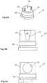
- the controllable for example by a control locking device 18 is variably adjustable. In an open position of the closing element 22 (FIG. Fig.
- the outlet nozzle is completely released.
- the closed position ( Fig. 3b )
- the outlet nozzle 12 is closed, so that no binder or water can escape at this outlet nozzle 12.
- no processed material 24 mixed with binders or water can penetrate into the nozzle channel 26 of the outlet nozzle 12 from the working space 6.
- the controller can set any intermediate positions in order to variably adapt the flow cross section through the outlet nozzle to the current working conditions.
- the closing element 22 can also be transferred into a cleaning position, which is beyond the closed position.
- the working space 6 facing the tip of the closing element 22 terminates at the working space 6 facing the end of the nozzle channel 26 and is preferably recessed relative to the working space 6 facing lateral surface 9 of the roller housing 8 to avoid damage to the closing element 22 during operation.
- Fig. 4 shows an embodiment of an outlet nozzle 12 at its nozzle inlet opening 28, which has a first portion 27 which conically narrows in the flow direction, and a downstream in the flow direction second portion 29 having a nozzle channel 26 with a constant cross-section.
- FIGS. 5a to 5c show another embodiment of the outlet nozzle 22, wherein the nozzle channel 26 preferably has a non-variable cross section and further preferably is cylindrical.
- the embodiments relate to the FIGS. 5a to 5c an embodiment in which in the first portion 27 of the outlet nozzle 12 is at least one recess 31 which may have different shapes.
- first section 27 a cross-sectionally a basically hollow cylindrical wall, wherein the recess 31 in the embodiment of Fig. 5a forms about half of a hollow cylinder. It is understood that the recess 31 may also have a smaller or larger circumference, or that a plurality of recesses 31 may be arranged in the generally hollow cylindrical first portion 27.
- Fig. 5b shows a first portion 27 of the outlet nozzle 12, in which the recess 31 tapers in the direction of flow of the outlet nozzle 12. Also in this embodiment, a plurality of such V-shaped recesses 31 may be distributed on the circumference of the first section.
- the first section 27 of the outlet nozzle 12 has an initially generally hollow cylindrical shape, wherein one or more circular recesses 31 may be arranged in the hollow cylinder forming the section 27.
- first portion 27 of the outlet nozzle 12 is mounted such that the recesses are acted upon from the outside with the fluid pressure of the injection.
- the nozzle cross section can be varied depending on the position of the closing element 22.
- Fig. 6 1 shows an exemplary embodiment of an outlet nozzle 12, in which the closing element 22 has a first outlet nozzle 12 facing portion 21 which has a smaller cross-sectional area than the cross-sectional area of the nozzle channel 26, while the second portion 23, in the flow direction of the outlet nozzle 12 behind the first Section 21 follows, is exactly adapted to the cross section of the nozzle channel 26 in order to close the nozzle channel 26 can.
- the section 21 may also have a continuously varying cross-sectional area, e.g. a conically tapering tip of the closing element 22.
- the closing element 22 can be controlled in an intermediate position between the open position and the closed position of the controller 11 such that an altered nozzle cross-section is adjustable.
- Fig. 6 with a tapering towards the tip closing element 22 is also with the embodiments of Fig. 4 and 5 combined.
- controller 11 can control the closing elements 22 such that the flow cross-section in the outlet nozzle 12 can be varied as a function of the position of the closing element 22.
- outlet nozzles can be controlled in the same way or individually by the controller.
- the closing element 22 can in another in Fig. 3c shown switching position in which the closing element 22 is moved beyond an additional stroke of the closing element 22 beyond the closed position, eliminate material accumulations of the processed material 24 in and / or in front of the outlet nozzle 12.
- Fig. 7 shows an embodiment of a spray bitumen spraying device 10 with a mixing device 36.
- the mixing device 36 has an expansion chamber 38 in which hot bitumen supplied via a bitumen injection nozzle 40 is miscible with water or with water and air to produce foam bitumen.
- expansion chamber 38 consists of a mixing chamber 42 and an injection chamber 44 connected to the mixing chamber 42, wherein the outlet nozzle 12 and the associated closing device 18 are arranged on the injection chamber 44.
- the hot bitumen is supplied via a ring line 15, wherein one of a controllable drive means actuated valve stem 46, the nozzle inlet opening of the bitumen injection nozzle 40 can close or release. Water or water and air can be supplied via one or two ports 41 of the mixing chamber 42.
- the mixing device 36 may be surrounded by a heating device 48, which prevent hardening of the bitumen during operation.
- the closing element 22 of the closing device 18 traverses the injection chamber 44 for closing or cleaning the outlet nozzle 12.
- controller drive devices such as electric motors, linear drives or the like. Can be used.
Landscapes
- Engineering & Computer Science (AREA)
- Structural Engineering (AREA)
- Civil Engineering (AREA)
- Architecture (AREA)
- Mining & Mineral Resources (AREA)
- Life Sciences & Earth Sciences (AREA)
- General Life Sciences & Earth Sciences (AREA)
- Mechanical Engineering (AREA)
- Soil Sciences (AREA)
- Agronomy & Crop Science (AREA)
- Environmental & Geological Engineering (AREA)
- Paleontology (AREA)
- General Engineering & Computer Science (AREA)
- Geology (AREA)
- Geochemistry & Mineralogy (AREA)
- Road Paving Machines (AREA)
- Nozzles (AREA)
- Road Repair (AREA)
Description
Die Erfindung betrifft eine Vorrichtung sowie ein Verfahren zum Bearbeiten von Böden oder Fahrbahnen nach dem Oberbegriff des Anspruchs 1 bzw.13.The invention relates to a device and a method for processing floors or roadways according to the preamble of
Der Oberbegriff geht aus von einem Stand der Technik wie er beispielsweise aus der
Die bekannten Vorrichtungen zum Bearbeiten von Böden oder Fahrbahnen, z.B. Bodenstabilisierer oder Recycler sind mit einer Arbeitswalze versehen, die Böden oder Fahrbahnen aufbricht und durchmischt. Im Falle von harten Fahrbahnen aus Asphalt oder Beton werden diese gefräst. Die Arbeitswalze ist von einem glockenförmigen Walzengehäuse umgeben, das den Arbeitsraum der Arbeitswalze umschließt, wobei dieser Arbeitsraum als Mischraum zum Mischen des abgearbeiteten Bodenmaterials mit einem Einsprühmittel, z.B. hydraulischen oder bituminösen Bindemitteln (Schaumbitumen, Emulsionen oder Suspensionen) oder mit Wasser dient. Alternativ können auch Bindemittel (z.B. Zement oder Kalk) vor dem Bodenstabilisierer/Recycler auf den Boden aufgebracht/gestreut werden.The known devices for processing of soils or roadways, eg soil stabilizer or recycler are provided with a work roll, breaks up the soil or roads and mixed. In the case of hard roads made of asphalt or concrete, these are milled. The work roll is surrounded by a bell-shaped roll housing which encloses the working space of the work roll, this working space serves as a mixing space for mixing the processed soil material with an injection, eg hydraulic or bituminous binders (foamed bitumen, emulsions or suspensions) or with water. Alternatively, binders (eg cement or lime) can also be applied to the soil before the soil stabilizer / recycler.
Bei anderen Bodenbearbeitungsmaschinen, wie zum Beispiel Straßenfräsmaschinen oder Surface-Minern kann eine Sprüheinrichtung zum Kühlen der Meißel vorgesehen sein.In other tillage machines, such as road milling machines or surface miners, a sprayer may be provided to cool the bits.
Die Einsprühmittel werden mit Hilfe einer an dem Walzengehäuse befestigten Sprüheinrichtung in den Arbeitsraum eingessprüht, wobei mehrere Austrittsdüsen der Sprüheinrichtung an dem Walzengehäuse in den Arbeitsraum gerichtet angeordnet sind.The spraying means are sprayed into the working space by means of a spraying device fastened to the roller housing, wherein several outlet nozzles of the spraying device are arranged on the roller housing in the working space.
Bei den bekannten Sprüheinrichtungen tritt das Problem auf, dass das Einsprühmittel über die Arbeitsbreite der Arbeitswalze ungleichmäßig in den Arbeitsraum eingebracht werden kann, insbesondere wenn nur ein geringes Volumen an Einsprühmittel erforderlich ist und/oder die Arbeitswalze mit der Sprüheinrichtung eine Querneigung zur Horizontalen aufweist. Im Falle einer Querneigung ergibt sich ein Druckgefälle längs der Sprüheinrichtung, so dass an den einzelnen Austrittsdüsen eine unterschiedliche Durchflussmenge austritt.In the known sprayers, the problem arises that the spraying can be introduced unevenly over the working width of the work roll in the working space, especially if only a small volume of spraying is required and / or the work roll with the spraying device has a bank to the horizontal. In the case of a bank, there is a pressure gradient along the spraying device, so that a different flow rate emerges at the individual outlet nozzles.
Die bekannten Austrittsdüsen können über ein stößelartiges Schließelement nur eingeschaltet oder ausgeschaltet werden oder mit Hilfe des Schließelementes eine Reinigungsfunktion ausführen. Die Reinigungsfunktion ist zweckmäßig, weil sich das mit Bindemitteln oder Wasser vermischte abgearbeitete Material selbst bei einem hohen Sprühdruck in die Austrittsdüsen hineindrücken oder sich im Bereich vor der Austrittsdüse ansammeln kann. Insbesondere nach einem Stillstand der Maschine besteht die Gefahr, dass die Austrittsdüsen durch abgebundenes oder ausgehärtetes oder getrocknetes, abgearbeitetes Material vom Arbeitsraum her verunreinigt und verstopft werden, wodurch die Sprühleistung vermindert wird oder sogar vollständig unterbunden wird.The known outlet nozzles can only be switched on or off via a tappet-like closing element or perform a cleaning function with the aid of the closing element. The cleaning function is expedient because the processed material mixed with binders or water can push into the outlet nozzles even at a high spray pressure or accumulate in the area in front of the outlet nozzle. In particular, after a standstill of the machine there is a risk that the outlet nozzles are contaminated by caked or hardened or dried, processed material from the working space ago and clogged, whereby the spray power is reduced or even completely prevented.
Es ist in Erwägung gezogen worden, die Durchflussmenge an den Austrittsdüsen mit Kugelhähnen, Drosselschiebern oder mit Irisblenden zu beeinflussen, um so eine gleichmäßige Ausbringung von Bindemitteln und/oder Wasser zu gewährleisten. Allerdings ist eine ausreichende Zuverlässigkeit dieser Systeme aufgrund ihrer Empfindlichkeit gegen thermische Ausdehnung und Verklebung der beweglichen Teile beispielsweise durch erstarrtes Bitumen nicht gegeben. Darüber hinaus bestehen Probleme durch den erhöhten Platzbedarf und Schwierigkeiten mit den zugehörigen Antriebseinrichtungen, sowie durch die komplizierte Automatisierung dieser Lösungsvorschläge.It has been considered to influence the flow rate at the outlet nozzles with ball valves, throttle valves or with iris diaphragms, in order to ensure a uniform application of binders and / or water. However, sufficient reliability of these systems due to their sensitivity to thermal expansion and bonding of the moving parts, for example by solidified bitumen is not given. In addition, there are problems due to the increased space requirements and difficulties with the associated drive devices, as well as the complicated automation of these proposed solutions.
Die
In dieser ventilähnlich gestalteten Vernebelungsdüse ist eine mit hoher Frequenz hin- und her bewegliche Nadel angeordnet, deren Spitze die Einspritzflüssigkeitsöffnung in zwei Endpositionen öffnen oder verschließen kann.In this valve-like designed nebulizer nozzle, a high-frequency reciprocating needle is arranged, the tip of which can open or close the injection fluid opening in two end positions.
Der Erfindung liegt daher die Aufgabe zugrunde, eine Vorrichtung und ein Verfahren zum Bearbeiten von Böden und Fahrbahnen mit in den Arbeitsraum gerichteten Austrittsdüsen einer Sprüheinrichtung dahingehend zu verbessern, dass über eine wählbare Arbeitsbreite eine gleichmäßige Ausbringung eines Einsprühmittels auch bei unterschiedlichen Volumenströmen, unterschiedlichen Einsprühmitteln und unterschiedlichen Querneigungen der Vorrichtung ermöglicht wird.The invention is therefore an object of the invention to improve an apparatus and a method for processing soils and roads with directed into the working space outlet nozzles of a sprayer to the effect that over a selectable working width uniform application of a spraying agent even with different flow rates, different spraying and different Banks of the device is enabled.
Zur Lösung dieser Aufgabe dienen die Merkmale des Anspruchs 1 bzw. 13.To solve this problem serve the features of
Die Erfindung sieht in vorteilhafter Weise vor, dass eine Steuerung die Schließeinrichtungen ansteuert, wobei die Austrittsdüsen und die zugehörigen Schließelemente derart einander angepasst sind, dass der Durchflussquerschnitt in der Austrittsdüse in Abhängigkeit von der Position des Schließelementes in einem vorgegebenen Weg zwischen der Offenstellung und der Schließstellung variierbar ist. Die vorgeschlagene Lösung hat den Vorteil, dass allein durch die gegenseitige Anpassung und Auslegung der Geometrie des Schließelementes und/oder der Austrittsdüse der aktuelle Durchflussquerschnitt in Abhängigkeit der Position des Schließelementes verändert werden kann, ohne dass zusätzliche Elemente notwendig sind. Die variable Einstellung der Schließelemente hat den Vorteil, dass bei niedrigen Durchflussraten der Druck an den einzelnen Austrittsdüsen aufrechterhalten wird. Ein besonderer Vorteil des variablen Durchflussquerschnittes beim Einsatz von Bindemitteln besteht darin, dass aufgrund der Gestaltung der Austrittsdüsen und/oder des Schließelementes die Austrittsdüsen sich nicht mit Bindemittel zusetzen können und die Funktion des Schließelementes behindern können.The invention advantageously provides that a control activates the closing devices, wherein the outlet nozzles and the associated closing elements are adapted to one another such that the flow cross-section in the outlet nozzle in dependence on the position of the closing element in a predetermined path between the open position and the closed position is variable. The proposed solution has the advantage that only by the mutual adaptation and interpretation of the geometry of the closing element and / or the outlet nozzle of the current flow area can be changed depending on the position of the closing element, without additional elements are necessary. The variable setting of the closing elements has the advantage that, at low flow rates, the pressure at the individual outlet nozzles is maintained becomes. A particular advantage of the variable flow cross-section when using binders is that due to the design of the outlet nozzles and / or the closing element, the outlet nozzles can not be clogged with binder and can hinder the function of the closing element.
Dabei werden alle Austrittsdüsen in.dividuell einzeln oder gemeinsam ansteuerbar und auch regelbar sein.In this case, all outlet nozzles in.dividuell be individually or jointly controllable and also controllable.
Die aus dem Stand der Technik gemäß
Erfindungsgemäß ist vorgesehen, dass die Steuerung die Schließelemente der einzelnen Austrittsdüsen in gleiche oder individuell unterschiedliche Zwischenpositionen positioniert. Die Steuerung kann damit unterschiedliche Druckverhältnisse an den einzelnen Austrittsdüsen automatisch ausgleichen oder auch bestimmte Austrittsdüsen selektiv ausschalten.According to the invention, it is provided that the control positions the closing elements of the individual outlet nozzles in identical or individually different intermediate positions. The controller can thus automatically compensate for different pressure conditions at the individual outlet nozzles or selectively switch off certain outlet nozzles.
Die Steuerung der Düsen kann dabei beispielsweise in Abhängigkeit vom Volumenstrom, oder in Abhängigkeit vom Druck in der Sprüheinrichtung oder in Abhängigkeit der Querneigung erfolgen.The control of the nozzles can be done, for example, depending on the volume flow, or in dependence on the pressure in the spray or in dependence of the bank.
Der mit der Austrittsdüse zusammenwirkende Teil des Schließelementes und/ oder die Austrittsdüse kann in Richtung einer zunehmenden Zustellbewegung des Schließelementes zur Schließstellung einen sich verringernden Durchflussquerschnitt zwischen dem Schließelement und der Austrittsdüse bilden. Die Durchflussmengensteuerung erfolgt somit allein aus dem Zusammenspiel zwischen der Position des Schließelementes und der Geometrie der Austrittsdüse und/oder des Schließelementes.The part of the closing element which cooperates with the outlet nozzle and / or the outlet nozzle can form a decreasing flow cross section between the closing element and the outlet nozzle in the direction of an increasing advancing movement of the closing element to the closed position. The flow rate control thus takes place solely on the interaction between the position of the closing element and the geometry of the outlet nozzle and / or the closing element.
Das Schließelement ist vorzugsweise koaxial zum Düsenkanal der Austrittsdüse bewegbar und positionierbar.The closing element is preferably movable and positionable coaxially with the nozzle channel of the outlet nozzle.
Das Schließelement kann z.B. von einer Kolbenstange einer mit einer Wegmesseinrichtung gekoppelten Antriebseinrichtung, wie z.B. einer Kolben-Zylindereinheit oder einem Linearmotor, einem Elektromotor, einem Spindelantrieb o.dgl. antreibbar sein, dessen Wegmesssignal der Steuerung zuführbar ist, um über ein Stellsignal für die Kolben-Zylindereinheit die aktuelle Position des Schließelementes zu steuern.The closing element can eg from a piston rod coupled to a path measuring device drive means, such as a piston-cylinder unit or a linear motor, an electric motor, a spindle drive or the like. be drivable whose position measurement signal can be supplied to the controller to control the current position of the closing element via a control signal for the piston-cylinder unit.
Bei einer bevorzugten Ausführungsform kann die Austrittdüse eine Düsengeometrie aufweisen, die in Abhängigkeit der Position des Schließelementes mit zunehmender Zustellung des Schließelementes zwischen der Offenstellung, in der der Düsenquerschnitt vollständig freigegeben ist, und der Schließstellung, in der der Düsenquerschnitt vollständig verschlossen ist, einen sich verringernden Durchflussquerschnitt zwischen Schließelement und Austrittsdüse durch eine Zwischenstellung des Schließelementes erzeugt.In a preferred embodiment, the outlet nozzle may have a nozzle geometry which, depending on the position of the closing element with increasing delivery of the closing element between the open position in which the nozzle cross section is fully released, and the closed position in which the nozzle cross section is completely closed, a decreasing Flow cross-section between the closing element and the outlet nozzle generated by an intermediate position of the closing element.
Dazu kann der Düsenkanal der Austrittsdüse eintrittsseitig einen sich bis zur Schließposition des Schließelementes erstreckenden ersten Abschnitt aufweisen, dessen Düsenquerschnitt sich in Durchflussrichtung der Austrittsdüse vorzugsweise konisch verengt.For this purpose, the nozzle channel of the outlet nozzle on the inlet side may have a first section extending up to the closing position of the closing element, the nozzle cross-section of which narrows conically in the direction of flow of the outlet nozzle.
Die Austrittsdüse kann alternativ eintrittsseitig einen sich bis zur Schließposition des Schließelementes erstreckenden ersten Abschnitt aufweisen, dessen Außenwand mindestens eine mit dem Einsprühmittel beaufschlagbare Aussparung aufweist.Alternatively, the outlet nozzle may have on the inlet side a first section extending up to the closing position of the closing element, the outer wall of which has at least one recess which can be acted upon by the spraying means.
Die Breite der Aussparung kann sich in Schließrichtung des Schließelementes verändern, vorzugsweise verringern.The width of the recess may change in the closing direction of the closing element, preferably reduce.
Alternativ kann das Schließelement, vorzugsweise bei einem konstanten Düsenquerschnitt an dem der Austrittsdüse zugewandten Ende einen vorzugsweise konisch oder stufenförmig verjüngten ersten Abschnitt aufweisen, an den sich ein an dem Düsenquerschnitt angepasster zweiter Abschnitt anschließt.Alternatively, the closing element, preferably with a constant nozzle cross-section at the end facing the outlet nozzle, may have a preferably conically or step-shaped tapered first section, which is adjoined by a second section adapted to the nozzle cross-section.
Die Steuerung kann den Durchflussquerschnitt aller Austrittsdüsen oder jeder einzelnen Austrittsdüse in Abhängigkeit der aktuell gewünschten Durchflussleistung und/oder des aktuell verwendeten Einsprühmittels und/oder der Querneigung der Sprüheinrichtung und/oder des Druckes in der Einsprühleiste steuern oder regeln.The controller can control or regulate the flow area of all the discharge nozzles or each individual discharge nozzle depending on the currently desired flow rate and / or the currently used spraying agent and / or the bank of the spraying device and / or the pressure in the spray bar.
Bei dem erfindungsgemäßen Verfahren zum Bearbeiten von Böden oder Fahrbahnen mit einer Vorrichtung mit einer Arbeitswalze und mindestens einer sich parallel zu der Arbeitswalze erstreckenden Sprüheinrichtung mit mehreren nebeneinander angeordneten, auf die Arbeitswalze gerichteten Austrittsdüsen für Einsprühmittel, z.B. Bindemittel, Wasser, Emulsionen, Suspensionen oder Schaumbitumen, wobei der Düsenkanal der Austrittsdüsen in einer Offenstellung während der Bearbeitung der Böden oder Fahrbahnen freigegeben und in einer Schließstellung bei Beendigung der Bearbeitung oder zur Anpassung an eine aktive Breite der Arbeitswalze verschlossen wird, ist vorgesehen, dass die Schließeinrichtungen für die Austrittsdüsen im Betrieb angesteuert werden können, wobei die Schließelemente der einzelnen Austrittsdüsen zwischen der Offenstellung und der Schließstellung in gleiche oder unterschiedliche Zwischenpositionen positioniert werden, und die Schließelemente mit den jeweiligen Düsenquerschnitten in den jeweiligen Zwischenpositionen derart zusammenwirken, dass ein variabel wählbarer Durchflussquerschnitt für die Austrittsdüsen in Abhängigkeit der Position der Schließelemente eingestellt wird.In the method according to the invention for working floors or roadways with a device having a work roll and at least one parallel to the work roll extending spray with several juxtaposed, directed to the work roll outlet nozzles for spraying, eg binders, water, emulsions, suspensions or foamed bitumen, wherein the nozzle channel of the outlet nozzles released in an open position during processing of the floors or lanes and in a closed position is closed at the end of processing or to adapt to an active width of the work roll, it is provided that the closing means for the outlet nozzles can be controlled during operation, wherein the closing elements of the individual outlet nozzles are positioned between the open position and the closed position in the same or different intermediate positions , And the closing elements with the respective nozzle cross-sections in the respective intermediate positions cooperate such that a variable selectable flow cross-section for the outlet nozzle n is set as a function of the position of the closing elements.
Dabei kann der Durchflussquerschnitt jeder einzelnen Austrittsdüse oder mehrerer Austrittsdüsen in Abhängigkeit der aktuell gewünschten Durchflussleistung und/oder des aktuell verwendeten Einsprühmittels und/oder der Querneigung der Sprüheinrichtung und/oder des Druckes in der Sprüheinrichtung gesteuert oder geregelt werden.In this case, the flow cross section of each individual outlet nozzle or several outlet nozzles can be controlled or regulated as a function of the currently desired flow rate and / or the currently used spraying agent and / or the bank of the spraying device and / or the pressure in the spraying device.
Ein variabler Durchflussquerschnitt zwischen dem Schließelement und der Austrittsdüse kann durch das Zusammenwirken der Geometrie der Austrittsdüse mit der Position des Schließelementes erzeugt werden.A variable flow area between the closing element and the outlet nozzle can be generated by the interaction of the geometry of the outlet nozzle with the position of the closing element.
Die Steuerung kann eine zusätzliche Bewegung des Schließelementes über die Schließstellung hinaus auslösen, mit der Materialanhäufungen in und/oder vor der Austrittsdüse beseitigbar sind.The control can trigger an additional movement of the closing element beyond the closed position with which accumulations of material in and / or in front of the outlet nozzle can be eliminated.
Insbesondere kann vorgesehen sein, dass die Austrittsdüse an einer Leitung oder an einer Einspritzkammer angeordnet ist, wobei das hydraulische oder bituminöse Bindemittel oder Wasser quer zur Austrittsdüse zuführbar ist. Das Schließelement durchquert zum Schließen oder Reinigen der Austrittsdüse die Leitung oder die Einspritzkammer und wird koaxial zu der Austrittsdüse geführt.In particular, it can be provided that the outlet nozzle is arranged on a line or on an injection chamber, wherein the hydraulic or bituminous binder or water can be fed transversely to the outlet nozzle. The closing element traverses the line or the injection chamber for closing or cleaning the outlet nozzle and is guided coaxially to the outlet nozzle.
Im Folgenden werden unter Bezugnahme auf die Zeichnungen Ausführungsbeispiele der Erfindung näher erläutert:
Es zeigen:
- Fig. 1
- eine Straßenbaumaschine,
- Fig. 2
- den Arbeitsraum einer Arbeitswalze unter einem Walzengehäuse mit Sprüheinrichtung,
- Fig. 3a bis 3c
- grundsätzliche Schaltstellungen des Schließelementes,
- Fig.4a und 4b
- eine Austrittsdüse mit einem anfangs konischen Düsenkanal,
- Fign. 5a bis 5c
- Austrittsdüsen mit einem Düsenkanal mit konstantem Querschnitt in drei unterschiedlichen Ausführungsformen,
- Fig. 6
- ein Schließelement mit veränderter Spitzengeometrie, und
- Fig. 7
- ein Ausführungsbeispiel einer Austrittsdüse für Schaumbitume.
Show it:
- Fig. 1
- a road construction machine,
- Fig. 2
- the working space of a work roll under a roll housing with spraying device,
- Fig. 3a to 3c
- basic switching positions of the closing element,
- 4a and 4b
- an outlet nozzle with an initially conical nozzle channel,
- FIGS. 5a to 5c
- Outlet nozzles with a nozzle channel with a constant cross-section in three different embodiments,
- Fig. 6
- a closure element with modified tip geometry, and
- Fig. 7
- an embodiment of an outlet nozzle for Schaumbitume.
Unterhalb des Maschinenrahmens 1 ist eine Arbeitswalze 4 in einem Walzengehäuse 8 angeordnet, die den Arbeitsraum 6 der Arbeitswalze 4 nach oben und zu den Seiten hin begrenzt. Eine detaillierte Beschreibung der in
Das Walzengehäuse 8 weist im oberen Bereich eine Sprüheinrichtung 10 auf, mit der beispielsweise Bindemittel oder Wasser mit mehreren vorzugsweise nebeneinander angeordneten Austrittsdüsen 12 in den Arbeitsraum 6 und auf die Arbeitswalze 4 einspritzbar ist.The
Das Bindemittel kann aus hydraulischen oder bituminösen Bindemitteln bestehen, und bei Mischungen aus hydraulischen Bindemitteln und Wasser aus Suspensionen z.B. Wasser-Zement-Suspension, bzw. bei Mischungen von bituminösen Bindemitteln mit Wasser aus Emulsionen. Desweiteren kann über die Austrittsdüsen 12 Schaumbitumen eingespritzt werden, wobei zur Herstellung von Schaumbitumen erhitztes, flüssiges Bitumen mit kaltem Wasser vermischt wird. Dadurch schäumt das Bitumen auf, wobei das ursprüngliche Volumen der Komponenten sich um etwa das 20-fache erhöht.The binder may consist of hydraulic or bituminous binders, and for mixtures of hydraulic binders and water from suspensions, e.g. Water-cement suspension, or in mixtures of bituminous binders with water from emulsions. Furthermore, foam bitumen can be injected via the outlet nozzles 12, wherein liquid bitumen heated to produce foamed bitumen is mixed with cold water. As a result, the bitumen foams up, whereby the original volume of the components increases approximately 20-fold.
Die Sprüheinrichtung 10 erhält das Bindemittel oder Wasser über eine Leitung 14, die eine Ringleitung sein kann. Das Bindemittel bzw. das Wasser strömt quer zur Austrittsdüse 12. Die an der Leitung 14 befestigte Austrittsdüse 12 ist in den Arbeitsraum 6 gerichtet und in einer der Austrittsdüse 12 angepassten Aussparung des Walzengehäuses 8 angeordnet. Die Werkzeuge 16 der Arbeitswalze haben einen Schnittkreis, der einen verhältnismäßig geringen Abstand zu dem Walzengehäuse 8, von beispielsweise ca. 50 mm, haben kann. Zu jeder Austrittdüse 12 ist eine Schließeinrichtung 18 vorgesehen, die aus einer Kolben-Zylindereinheit 20 besteht, deren Kolbenstange ein Schließelement 22 für die Austrittsdüse 12 bildet oder antreibt. Die beispielsweise von einer Steuerung ansteuerbare Schließeinrichtung 18 ist variabel einstellbar. In einer Offenstellung des Schließelementes 22 (
Die dem Arbeitsraum 6 zugewandte Spitze des Schließelementes 22 endet an dem dem Arbeitsraum 6 zugewandten Ende des Düsenkanals 26 und ist gegenüber der dem Arbeitsraum 6 zugewandten Mantelfläche 9 des Walzengehäuses 8 vorzugsweise zurückversetzt, um Beschädigungen des Schließelementes 22 im Betrieb zu vermeiden.The working
Je nach Position des zylindrischen Schließelementes 22 ergibt sich, wenn das Schließelement 22 sich im Bereich der Austrittsdüse 12 befindet, ein unterschiedlicher Durchflussquerschnitt in Abhängigkeit von der variablen Position des Schließelementes 22.Depending on the position of the
Es versteht sich, dass in Abwandlung des Ausführungsbeispiels der
Die
Generell betreffen die Ausführungsbeispiele der
In dem Ausführungsbeispiel der
Das Ausführungsbeispiel der
Bei dem Ausführungsbeispiel der
Schließlich können auch unterschiedlich gestaltete Aussparungen bei allen Ausführungsbeispielen der
Es versteht sich, dass der erste Abschnitt 27 der Austrittsdüse 12 derart montiert ist, dass die Aussparungen von der Außenseite her mit dem Fluiddruck des Einsprühmittels beaufschlagt sind.It is understood that the
Grundsätzlich besteht auch die Möglichkeit, die Gestaltung des ersten Abschnitts 27 gemäß
Bei allen Ausführungsbeispielen kann demzufolge der Düsenquerschnitt in Abhängigkeit der Stellung des Schließelementes 22 variiert werden.Accordingly, in all embodiments, the nozzle cross section can be varied depending on the position of the
Der Abschnitt 21 kann auch eine sich stetig ändernde Querschnittsfläche aufweisen, z.B. eine sich konisch verjüngende Spitze des Schließelementes 22.The
Auch hier kann das Schließelement 22 in einer Zwischenstellung zwischen der Offenstellung und der Schließstellung von der Steuerung 11 derart angesteuert werden, dass ein veränderter Düsenquerschnitt einstellbar ist.Again, the closing
Das Ausführungsbeispiel der
Für alle Ausführungsbeispiele der
Dabei können mehrere Austrittsdüsen in gleicher Weise oder individuell von der Steuerung angesteuert werden.In this case, several outlet nozzles can be controlled in the same way or individually by the controller.
Das Schließelement 22 kann in einer weiteren in
Die Mischeinrichtung 36 kann von einer Heizeinrichtung 48 umgeben sein, die im Betrieb ein Aushärten des Bitumens verhindern. Das Schließelement 22 der Schließeinrichtung 18 durchquert zum Verschließen oder Reinigen der Austrittsdüse 12 die Einspritzkammer 44.The mixing
Es versteht sich, dass auch andere von der Steuerung ansteuerbare Antriebseinrichtungen wie Elektromotoren, Linearantriebe oder dgl. zum Einsatz kommen können.It is understood that other controllable by the controller drive devices such as electric motors, linear drives or the like. Can be used.
Claims (14)
- Device for working ground surfaces or roadways, comprising a machine frame (1) on which a working drum (4) is arranged within a drum housing (8), wherein at least one spraying device (10), extending parallel to the working drum and comprising a plurality of outlet nozzles (12) for spraying agents arranged next to one another and directed towards the working drum, is arranged at the drum housing (8), wherein the outlet nozzles (12) each comprise one drivable closing mechanism (18) with a closing element (22) which, in an open position, fully uncovers the nozzle channel (26) of the outlet nozzle (12) and, in a closed position, closes the nozzle channel (26),
characterized in that
a controller (11) drives the closing mechanisms (18), with the outlet nozzles (12) and the related closing elements (22) being adapted to one another in such a fashion that the flow cross-section in the outlet nozzle (12) is variable in accordance with the position of the closing element (22) on a specified path between the open position and closed position, and
that the closing elements (22) of the individual outlet nozzles are positionable by the controller (11) in identical or individually different intermediate positions. - Device in accordance with claim 1, characterized in that the part of the closing element (22) interacting with the outlet nozzle (12) and/or the outlet nozzle (12), in the direction of an increasing positioning movement of the closing element (22) towards the closed position, form a decreasing flow cross-section between the closing element (22) and the outlet nozzle (12).
- Device in accordance with claim 1 or 2, characterized in that the closing element (22) is movable and positionable coaxially to the nozzle channel of the outlet nozzle (12).
- Device in accordance with any one of claims 1 to 3, characterized in that the outlet nozzle (12) comprises a nozzle geometry which, in accordance with the position of the closing element (22), with an increasing positioning movement of the closing element between the open position and the closed position, creates a decreasing flow cross-section between the closing element and the outlet nozzle.
- Device in accordance with any one claims 1 to 4, characterized in that the closing element is drivable by a driving device coupled with a displacement measuring device, the measured displacement signal of which can be supplied to the controller in order to control the current position of the closing element via an actuation signal for the driving device.
- Device in accordance with any one of claims 1 to 5, characterized in that the controller is adapted to trigger an additional movement of the closing element (22) beyond the closed position which is effective to remove material accumulations in and/or in front of the outlet nozzle (12).
- Device in accordance with any one of claims 1 to 6, characterized in that the nozzle channel (26) of the outlet nozzle (12) comprises, on the inlet side, a first section (27) extending up to the closed position of the closing element (22), the nozzle cross-section of which narrows preferably conically in the direction of flow of the outlet nozzle (12), or that the closing element (22), at the end facing toward the outlet nozzle (12), comprises a section (21) tapering preferably conically which is followed by a section (23) adapted to the nozzle cross-section for closing the outlet nozzle (12).
- Device in accordance with any one of claims 1 to 6, characterized in that the outlet nozzle (12), on the inlet side, comprises a first section (27) extending up to the closed position of the closing element (22), the outer wall of which comprises at least one cut-out (31) suitable to have the spraying agent applied on it.
- Device in accordance with claim 8, characterized in that the width of the cut-out (31) changes in the closing direction of the closing element (22).
- Device in accordance with claim 8 or 9, characterized in that the nozzle channel of the outlet nozzle (12) has a constant nozzle cross-section.
- Device in accordance with any one of claims 1 to 10, characterized in that the controller controls or regulates the flow cross-section of each individual outlet nozzle or of a plurality of outlet nozzles jointly in accordance with the currently specified flow rate and/or the currently used spraying agent and/or the transverse slope of the spraying device and/or the pressure in the spraying device.
- Method for working ground surfaces or roadways, comprising a device with a working drum (4) and at least one spraying device (10) extending parallel to the working drum and comprising a plurality outlet nozzles (12) for spraying agents arranged next to one another and directed towards the working drum, wherein the nozzle channel of the outlet nozzles (12) is fully uncovered by a closing mechanism (18) in an open position when working the ground surfaces or roadways, and is closed in a closed position at the termination of the working operation or for adjustment to an active width of the working drum,
characterized by
driving the closing mechanisms (18) during the working operation, wherein the closing elements (22) of the outlet nozzles, between the open position and the closed position, can be positioned in identical or different intermediate positions and wherein the closing elements interact with the respective nozzle cross-sections in the respective intermediate positions in such a fashion that a variably selectable flow cross-section for each outlet nozzle is adjusted in accordance with the position of the closing elements. - Method in accordance with claim 12, characterized in that the flow cross-section of a plurality of outlet nozzles or each individual outlet nozzle is controlled or regulated in accordance with the currently specified flow rate and/or the currently used spraying agent and/or the transverse slope of the spraying device and/or the pressure in the spraying device.
- Method in accordance with claim 12 or 13, characterized in that a variable flow cross-section between the closing element and the outlet nozzle is generated by the interaction of the geometry of the outlet nozzle with the position of the closing element.
Applications Claiming Priority (1)
| Application Number | Priority Date | Filing Date | Title |
|---|---|---|---|
| DE201310016515 DE102013016515A1 (en) | 2013-10-07 | 2013-10-07 | Device and method for working floors or roads |
Publications (2)
| Publication Number | Publication Date |
|---|---|
| EP2857108A1 EP2857108A1 (en) | 2015-04-08 |
| EP2857108B1 true EP2857108B1 (en) | 2019-07-10 |
Family
ID=51625966
Family Applications (1)
| Application Number | Title | Priority Date | Filing Date |
|---|---|---|---|
| EP14187128.5A Active EP2857108B1 (en) | 2013-10-07 | 2014-09-30 | Device and method for machining soil or roadways |
Country Status (4)
| Country | Link |
|---|---|
| US (3) | US9376774B2 (en) |
| EP (1) | EP2857108B1 (en) |
| CN (2) | CN204162984U (en) |
| DE (1) | DE102013016515A1 (en) |
Families Citing this family (11)
| Publication number | Priority date | Publication date | Assignee | Title |
|---|---|---|---|---|
| DE102013016515A1 (en) | 2013-10-07 | 2015-04-09 | Wirtgen Gmbh | Device and method for working floors or roads |
| DE102014015589A1 (en) * | 2014-10-21 | 2016-04-21 | Bomag Gmbh | Fluid delivery device, injection device, ground milling machine and method |
| US20160326701A1 (en) * | 2015-05-07 | 2016-11-10 | Caterpillar Paving Products Inc. | Rotary Mixer with Automated Control Functions |
| AU2017342738B2 (en) * | 2016-10-11 | 2020-03-12 | Roadtec, Inc. | Cold in-place recycling machine with surge tank |
| DE102017100165A1 (en) | 2017-01-05 | 2018-07-05 | Jabil Optics Germany GmbH | Light-emitting device and light-emitting system |
| US10000894B1 (en) | 2017-09-18 | 2018-06-19 | Caterpillar Paving Products Inc. | Spray bar assembly for machine system, and method |
| US10273640B1 (en) * | 2018-05-10 | 2019-04-30 | Caterpillar Sarl | Paving machine with emulsion spray bar |
| US10406542B1 (en) * | 2018-06-01 | 2019-09-10 | Caterpillar Paving Products Inc. | Foamed bitumen dispensing device |
| CN110004811B (en) * | 2019-04-29 | 2023-06-02 | 长安大学 | Hot air heating device for serial asphalt pavement and heating control method thereof |
| US11674272B2 (en) * | 2021-04-19 | 2023-06-13 | WTD Heat Technology Ltd. | Low-emission hot-in-place asphalt recycling equipment train system |
| CN115247396B (en) * | 2022-07-14 | 2023-10-10 | 中交二公局第四工程有限公司 | Construction equipment is filled to high and cold district lime soil subgrade |
Family Cites Families (18)
| Publication number | Priority date | Publication date | Assignee | Title |
|---|---|---|---|---|
| US5294210A (en) * | 1992-06-19 | 1994-03-15 | Jerome Lemelson | Automated pothole sensing and filling apparatus |
| GB9312397D0 (en) * | 1993-06-16 | 1993-07-28 | Lurmark Ltd | Nozzle assembly |
| DE19504495A1 (en) | 1995-02-12 | 1996-08-22 | Wirtgen Gmbh | Road surface renewal machine |
| US5707010A (en) * | 1995-09-29 | 1998-01-13 | Spraying Systems Co. | Controllable spray nozzle assembly |
| US5827360A (en) * | 1996-10-09 | 1998-10-27 | Cmi Corporation | Method and equipment for producing foam bitumen |
| DE29702162U1 (en) | 1997-02-08 | 1998-06-10 | Wirtgen Gmbh | Device for processing roadways, and device for producing foamed bitumen |
| US6755482B2 (en) * | 2001-05-25 | 2004-06-29 | Surface Preparation Technologies, Inc. | Cutting machine with flywheel gearbox design and method for use |
| DE10241067B3 (en) | 2002-09-05 | 2004-04-22 | Wirtgen Gmbh | Device for working floors or roadways |
| US7794215B2 (en) * | 2007-02-12 | 2010-09-14 | Regency Technologies Llc | High pressure slurry plunger pump with clean fluid valve arrangement |
| US8177456B2 (en) * | 2007-12-21 | 2012-05-15 | Asphalt Zipper, Inc. | Pavement milling assembly |
| US8899501B2 (en) * | 2008-07-23 | 2014-12-02 | Sata Gmbh & Co. Kg | Spray gun with paint cartridge |
| US9089869B2 (en) * | 2010-02-18 | 2015-07-28 | Adco Products, Llc | Adhesive bead applicator |
| DE102010014904A1 (en) * | 2010-04-14 | 2011-10-20 | Bomag Gmbh | Spraying device for a construction machine and method for operating a spraying device |
| DE102010051551A1 (en) | 2010-11-18 | 2012-05-24 | Wirtgen Gmbh | Soil cultivation machine and method for milling floors or traffic areas |
| CN202157264U (en) * | 2011-07-08 | 2012-03-07 | 沈阳北方交通重工有限公司 | Full-automatic water pump intelligent control spraying system of milling machine |
| US9463484B2 (en) * | 2013-05-31 | 2016-10-11 | Crown Beds, Inc. | Spray assembly for surface treatment |
| DE102013016515A1 (en) | 2013-10-07 | 2015-04-09 | Wirtgen Gmbh | Device and method for working floors or roads |
| US9108214B2 (en) * | 2013-10-31 | 2015-08-18 | Nordson Corporation | Dispensing module having a sealing zone and method for dispensing an adhesive |
-
2013
- 2013-10-07 DE DE201310016515 patent/DE102013016515A1/en not_active Withdrawn
-
2014
- 2014-09-30 EP EP14187128.5A patent/EP2857108B1/en active Active
- 2014-10-03 US US14/505,660 patent/US9376774B2/en active Active
- 2014-10-08 CN CN201420578900.XU patent/CN204162984U/en not_active Withdrawn - After Issue
- 2014-10-08 CN CN201410525125.6A patent/CN104514194B/en active Active
-
2016
- 2016-06-22 US US15/189,194 patent/US9598825B2/en active Active
-
2017
- 2017-03-14 US US15/458,162 patent/US10066347B2/en active Active
Non-Patent Citations (1)
| Title |
|---|
| None * |
Also Published As
| Publication number | Publication date |
|---|---|
| CN104514194A (en) | 2015-04-15 |
| CN204162984U (en) | 2015-02-18 |
| DE102013016515A1 (en) | 2015-04-09 |
| US9376774B2 (en) | 2016-06-28 |
| US9598825B2 (en) | 2017-03-21 |
| US20150098760A1 (en) | 2015-04-09 |
| US10066347B2 (en) | 2018-09-04 |
| US20170016186A1 (en) | 2017-01-19 |
| US20180030676A1 (en) | 2018-02-01 |
| CN104514194B (en) | 2016-11-30 |
| EP2857108A1 (en) | 2015-04-08 |
Similar Documents
| Publication | Publication Date | Title |
|---|---|---|
| EP2857108B1 (en) | Device and method for machining soil or roadways | |
| EP2423384B1 (en) | Spray device for a construction machine for earth works, construction machine with a spray device and method for operating a spray device | |
| EP1396581B3 (en) | Apparatus for treating soil or roads | |
| EP3185680B1 (en) | Agricultural sprayer comprising a system for the automatic control of spraying profiles | |
| EP2886717B1 (en) | After-treatment machine and method for the subsequent processing of a freshly made concrete layer | |
| WO1998035102A1 (en) | Device for paving roadways and device for producing foamed bitumen | |
| EP2022329A2 (en) | Moveable spray assembly with a spray boom and method for adjusting its spray nozzles | |
| DE102010014904A1 (en) | Spraying device for a construction machine and method for operating a spraying device | |
| DE102004010245A1 (en) | Apparatus and method for applying liquid substances, in particular of lubricants to a nonwoven web | |
| EP3058820A1 (en) | Method for motion control, and/or regulation of an agricultural distribution device | |
| EP2346624A1 (en) | Device for cooling a roll in a roll stand | |
| DE2149285A1 (en) | DEVICE FOR DISPENSING LIQUID PLASTIC COATING ON STREET SURFACES | |
| EP3649857A1 (en) | Agricultural sprayer | |
| EP3293310B1 (en) | Road finisher with spraying device | |
| DE102014015589A1 (en) | Fluid delivery device, injection device, ground milling machine and method | |
| EP3539375A1 (en) | Distributed system and method for the application of sprayed fluids for an agricultural field spraying device | |
| EP2712691B1 (en) | Device and method for secondary cooling in a casting machine | |
| EP0882839A2 (en) | Apparatus and method for the application of a liquid or pasty fluid to a moving web | |
| EP3485728B1 (en) | Agricultural distributor | |
| EP2932841A1 (en) | Application vehicle | |
| DE102016122946A1 (en) | Method for controlling a centrifugal spreader for fertilizer in the border area to a headland | |
| EP3713687B1 (en) | Method for cooling a metallic item and cooling bar | |
| EP1312488A2 (en) | Device for spreading grit | |
| EP1489232A2 (en) | Apparatus for applying a binder for an asphaltic paving on a traffic surface | |
| EP3804516A1 (en) | Agricultural distributor, preferably a field sprayer or a fertilizer spreader |
Legal Events
| Date | Code | Title | Description |
|---|---|---|---|
| PUAI | Public reference made under article 153(3) epc to a published international application that has entered the european phase |
Free format text: ORIGINAL CODE: 0009012 |
|
| 17P | Request for examination filed |
Effective date: 20140930 |
|
| AK | Designated contracting states |
Kind code of ref document: A1 Designated state(s): AL AT BE BG CH CY CZ DE DK EE ES FI FR GB GR HR HU IE IS IT LI LT LU LV MC MK MT NL NO PL PT RO RS SE SI SK SM TR |
|
| AX | Request for extension of the european patent |
Extension state: BA ME |
|
| R17P | Request for examination filed (corrected) |
Effective date: 20151006 |
|
| RBV | Designated contracting states (corrected) |
Designated state(s): AL AT BE BG CH CY CZ DE DK EE ES FI FR GB GR HR HU IE IS IT LI LT LU LV MC MK MT NL NO PL PT RO RS SE SI SK SM TR |
|
| RIC1 | Information provided on ipc code assigned before grant |
Ipc: E01C 23/06 20060101ALI20181109BHEP Ipc: B05B 13/00 20060101ALI20181109BHEP Ipc: B05B 15/522 20180101ALI20181109BHEP Ipc: E01C 23/00 20060101ALI20181109BHEP Ipc: B05B 15/50 20180101ALI20181109BHEP Ipc: E02D 3/00 20060101ALI20181109BHEP Ipc: E01C 23/12 20060101ALI20181109BHEP Ipc: B05B 12/12 20060101AFI20181109BHEP Ipc: E01C 19/17 20060101ALI20181109BHEP Ipc: B05B 1/30 20060101ALI20181109BHEP Ipc: E01C 21/00 20060101ALI20181109BHEP |
|
| GRAP | Despatch of communication of intention to grant a patent |
Free format text: ORIGINAL CODE: EPIDOSNIGR1 |
|
| STAA | Information on the status of an ep patent application or granted ep patent |
Free format text: STATUS: GRANT OF PATENT IS INTENDED |
|
| INTG | Intention to grant announced |
Effective date: 20190122 |
|
| GRAS | Grant fee paid |
Free format text: ORIGINAL CODE: EPIDOSNIGR3 |
|
| GRAA | (expected) grant |
Free format text: ORIGINAL CODE: 0009210 |
|
| STAA | Information on the status of an ep patent application or granted ep patent |
Free format text: STATUS: THE PATENT HAS BEEN GRANTED |
|
| AK | Designated contracting states |
Kind code of ref document: B1 Designated state(s): AL AT BE BG CH CY CZ DE DK EE ES FI FR GB GR HR HU IE IS IT LI LT LU LV MC MK MT NL NO PL PT RO RS SE SI SK SM TR |
|
| REG | Reference to a national code |
Ref country code: GB Ref legal event code: FG4D Free format text: NOT ENGLISH |
|
| REG | Reference to a national code |
Ref country code: CH Ref legal event code: EP Ref country code: AT Ref legal event code: REF Ref document number: 1152958 Country of ref document: AT Kind code of ref document: T Effective date: 20190715 |
|
| REG | Reference to a national code |
Ref country code: DE Ref legal event code: R096 Ref document number: 502014012163 Country of ref document: DE |
|
| REG | Reference to a national code |
Ref country code: IE Ref legal event code: FG4D Free format text: LANGUAGE OF EP DOCUMENT: GERMAN |
|
| REG | Reference to a national code |
Ref country code: SE Ref legal event code: TRGR |
|
| REG | Reference to a national code |
Ref country code: NL Ref legal event code: MP Effective date: 20190710 |
|
| REG | Reference to a national code |
Ref country code: LT Ref legal event code: MG4D |
|
| PG25 | Lapsed in a contracting state [announced via postgrant information from national office to epo] |
Ref country code: LT Free format text: LAPSE BECAUSE OF FAILURE TO SUBMIT A TRANSLATION OF THE DESCRIPTION OR TO PAY THE FEE WITHIN THE PRESCRIBED TIME-LIMIT Effective date: 20190710 Ref country code: NL Free format text: LAPSE BECAUSE OF FAILURE TO SUBMIT A TRANSLATION OF THE DESCRIPTION OR TO PAY THE FEE WITHIN THE PRESCRIBED TIME-LIMIT Effective date: 20190710 Ref country code: BG Free format text: LAPSE BECAUSE OF FAILURE TO SUBMIT A TRANSLATION OF THE DESCRIPTION OR TO PAY THE FEE WITHIN THE PRESCRIBED TIME-LIMIT Effective date: 20191010 Ref country code: FI Free format text: LAPSE BECAUSE OF FAILURE TO SUBMIT A TRANSLATION OF THE DESCRIPTION OR TO PAY THE FEE WITHIN THE PRESCRIBED TIME-LIMIT Effective date: 20190710 Ref country code: PT Free format text: LAPSE BECAUSE OF FAILURE TO SUBMIT A TRANSLATION OF THE DESCRIPTION OR TO PAY THE FEE WITHIN THE PRESCRIBED TIME-LIMIT Effective date: 20191111 Ref country code: HR Free format text: LAPSE BECAUSE OF FAILURE TO SUBMIT A TRANSLATION OF THE DESCRIPTION OR TO PAY THE FEE WITHIN THE PRESCRIBED TIME-LIMIT Effective date: 20190710 Ref country code: NO Free format text: LAPSE BECAUSE OF FAILURE TO SUBMIT A TRANSLATION OF THE DESCRIPTION OR TO PAY THE FEE WITHIN THE PRESCRIBED TIME-LIMIT Effective date: 20191010 |
|
| PG25 | Lapsed in a contracting state [announced via postgrant information from national office to epo] |
Ref country code: RS Free format text: LAPSE BECAUSE OF FAILURE TO SUBMIT A TRANSLATION OF THE DESCRIPTION OR TO PAY THE FEE WITHIN THE PRESCRIBED TIME-LIMIT Effective date: 20190710 Ref country code: IS Free format text: LAPSE BECAUSE OF FAILURE TO SUBMIT A TRANSLATION OF THE DESCRIPTION OR TO PAY THE FEE WITHIN THE PRESCRIBED TIME-LIMIT Effective date: 20191110 Ref country code: LV Free format text: LAPSE BECAUSE OF FAILURE TO SUBMIT A TRANSLATION OF THE DESCRIPTION OR TO PAY THE FEE WITHIN THE PRESCRIBED TIME-LIMIT Effective date: 20190710 Ref country code: ES Free format text: LAPSE BECAUSE OF FAILURE TO SUBMIT A TRANSLATION OF THE DESCRIPTION OR TO PAY THE FEE WITHIN THE PRESCRIBED TIME-LIMIT Effective date: 20190710 Ref country code: GR Free format text: LAPSE BECAUSE OF FAILURE TO SUBMIT A TRANSLATION OF THE DESCRIPTION OR TO PAY THE FEE WITHIN THE PRESCRIBED TIME-LIMIT Effective date: 20191011 Ref country code: AL Free format text: LAPSE BECAUSE OF FAILURE TO SUBMIT A TRANSLATION OF THE DESCRIPTION OR TO PAY THE FEE WITHIN THE PRESCRIBED TIME-LIMIT Effective date: 20190710 |
|
| PG25 | Lapsed in a contracting state [announced via postgrant information from national office to epo] |
Ref country code: TR Free format text: LAPSE BECAUSE OF FAILURE TO SUBMIT A TRANSLATION OF THE DESCRIPTION OR TO PAY THE FEE WITHIN THE PRESCRIBED TIME-LIMIT Effective date: 20190710 |
|
| PG25 | Lapsed in a contracting state [announced via postgrant information from national office to epo] |
Ref country code: DK Free format text: LAPSE BECAUSE OF FAILURE TO SUBMIT A TRANSLATION OF THE DESCRIPTION OR TO PAY THE FEE WITHIN THE PRESCRIBED TIME-LIMIT Effective date: 20190710 Ref country code: PL Free format text: LAPSE BECAUSE OF FAILURE TO SUBMIT A TRANSLATION OF THE DESCRIPTION OR TO PAY THE FEE WITHIN THE PRESCRIBED TIME-LIMIT Effective date: 20190710 Ref country code: EE Free format text: LAPSE BECAUSE OF FAILURE TO SUBMIT A TRANSLATION OF THE DESCRIPTION OR TO PAY THE FEE WITHIN THE PRESCRIBED TIME-LIMIT Effective date: 20190710 Ref country code: RO Free format text: LAPSE BECAUSE OF FAILURE TO SUBMIT A TRANSLATION OF THE DESCRIPTION OR TO PAY THE FEE WITHIN THE PRESCRIBED TIME-LIMIT Effective date: 20190710 |
|
| PG25 | Lapsed in a contracting state [announced via postgrant information from national office to epo] |
Ref country code: SM Free format text: LAPSE BECAUSE OF FAILURE TO SUBMIT A TRANSLATION OF THE DESCRIPTION OR TO PAY THE FEE WITHIN THE PRESCRIBED TIME-LIMIT Effective date: 20190710 Ref country code: SK Free format text: LAPSE BECAUSE OF FAILURE TO SUBMIT A TRANSLATION OF THE DESCRIPTION OR TO PAY THE FEE WITHIN THE PRESCRIBED TIME-LIMIT Effective date: 20190710 Ref country code: IS Free format text: LAPSE BECAUSE OF FAILURE TO SUBMIT A TRANSLATION OF THE DESCRIPTION OR TO PAY THE FEE WITHIN THE PRESCRIBED TIME-LIMIT Effective date: 20200224 Ref country code: MC Free format text: LAPSE BECAUSE OF FAILURE TO SUBMIT A TRANSLATION OF THE DESCRIPTION OR TO PAY THE FEE WITHIN THE PRESCRIBED TIME-LIMIT Effective date: 20190710 Ref country code: CZ Free format text: LAPSE BECAUSE OF FAILURE TO SUBMIT A TRANSLATION OF THE DESCRIPTION OR TO PAY THE FEE WITHIN THE PRESCRIBED TIME-LIMIT Effective date: 20190710 |
|
| REG | Reference to a national code |
Ref country code: CH Ref legal event code: PL |
|
| REG | Reference to a national code |
Ref country code: DE Ref legal event code: R097 Ref document number: 502014012163 Country of ref document: DE |
|
| PLBE | No opposition filed within time limit |
Free format text: ORIGINAL CODE: 0009261 |
|
| STAA | Information on the status of an ep patent application or granted ep patent |
Free format text: STATUS: NO OPPOSITION FILED WITHIN TIME LIMIT |
|
| PG2D | Information on lapse in contracting state deleted |
Ref country code: IS |
|
| PG25 | Lapsed in a contracting state [announced via postgrant information from national office to epo] |
Ref country code: LI Free format text: LAPSE BECAUSE OF NON-PAYMENT OF DUE FEES Effective date: 20190930 Ref country code: IE Free format text: LAPSE BECAUSE OF NON-PAYMENT OF DUE FEES Effective date: 20190930 Ref country code: LU Free format text: LAPSE BECAUSE OF NON-PAYMENT OF DUE FEES Effective date: 20190930 Ref country code: CH Free format text: LAPSE BECAUSE OF NON-PAYMENT OF DUE FEES Effective date: 20190930 |
|
| REG | Reference to a national code |
Ref country code: BE Ref legal event code: MM Effective date: 20190930 |
|
| 26N | No opposition filed |
Effective date: 20200603 |
|
| PG25 | Lapsed in a contracting state [announced via postgrant information from national office to epo] |
Ref country code: SI Free format text: LAPSE BECAUSE OF FAILURE TO SUBMIT A TRANSLATION OF THE DESCRIPTION OR TO PAY THE FEE WITHIN THE PRESCRIBED TIME-LIMIT Effective date: 20190710 Ref country code: BE Free format text: LAPSE BECAUSE OF NON-PAYMENT OF DUE FEES Effective date: 20190930 |
|
| REG | Reference to a national code |
Ref country code: AT Ref legal event code: MM01 Ref document number: 1152958 Country of ref document: AT Kind code of ref document: T Effective date: 20190930 |
|
| PG25 | Lapsed in a contracting state [announced via postgrant information from national office to epo] |
Ref country code: AT Free format text: LAPSE BECAUSE OF NON-PAYMENT OF DUE FEES Effective date: 20190930 |
|
| PG25 | Lapsed in a contracting state [announced via postgrant information from national office to epo] |
Ref country code: CY Free format text: LAPSE BECAUSE OF FAILURE TO SUBMIT A TRANSLATION OF THE DESCRIPTION OR TO PAY THE FEE WITHIN THE PRESCRIBED TIME-LIMIT Effective date: 20190710 |
|
| PG25 | Lapsed in a contracting state [announced via postgrant information from national office to epo] |
Ref country code: MT Free format text: LAPSE BECAUSE OF FAILURE TO SUBMIT A TRANSLATION OF THE DESCRIPTION OR TO PAY THE FEE WITHIN THE PRESCRIBED TIME-LIMIT Effective date: 20190710 Ref country code: HU Free format text: LAPSE BECAUSE OF FAILURE TO SUBMIT A TRANSLATION OF THE DESCRIPTION OR TO PAY THE FEE WITHIN THE PRESCRIBED TIME-LIMIT; INVALID AB INITIO Effective date: 20140930 |
|
| PG25 | Lapsed in a contracting state [announced via postgrant information from national office to epo] |
Ref country code: MK Free format text: LAPSE BECAUSE OF FAILURE TO SUBMIT A TRANSLATION OF THE DESCRIPTION OR TO PAY THE FEE WITHIN THE PRESCRIBED TIME-LIMIT Effective date: 20190710 |
|
| P01 | Opt-out of the competence of the unified patent court (upc) registered |
Effective date: 20230525 |
|
| PGFP | Annual fee paid to national office [announced via postgrant information from national office to epo] |
Ref country code: GB Payment date: 20230921 Year of fee payment: 10 |
|
| PGFP | Annual fee paid to national office [announced via postgrant information from national office to epo] |
Ref country code: SE Payment date: 20230921 Year of fee payment: 10 Ref country code: FR Payment date: 20230918 Year of fee payment: 10 Ref country code: DE Payment date: 20230919 Year of fee payment: 10 |
|
| PGFP | Annual fee paid to national office [announced via postgrant information from national office to epo] |
Ref country code: IT Payment date: 20230929 Year of fee payment: 10 |