EP2857082A1 - Filter apparatus with self-regulating cleaning - Google Patents
Filter apparatus with self-regulating cleaning Download PDFInfo
- Publication number
- EP2857082A1 EP2857082A1 EP13187103.0A EP13187103A EP2857082A1 EP 2857082 A1 EP2857082 A1 EP 2857082A1 EP 13187103 A EP13187103 A EP 13187103A EP 2857082 A1 EP2857082 A1 EP 2857082A1
- Authority
- EP
- European Patent Office
- Prior art keywords
- pressure
- filter
- control unit
- differential pressure
- cleaning
- Prior art date
- Legal status (The legal status is an assumption and is not a legal conclusion. Google has not performed a legal analysis and makes no representation as to the accuracy of the status listed.)
- Withdrawn
Links
Images
Classifications
-
- B—PERFORMING OPERATIONS; TRANSPORTING
- B01—PHYSICAL OR CHEMICAL PROCESSES OR APPARATUS IN GENERAL
- B01D—SEPARATION
- B01D46/00—Filters or filtering processes specially modified for separating dispersed particles from gases or vapours
- B01D46/42—Auxiliary equipment or operation thereof
- B01D46/44—Auxiliary equipment or operation thereof controlling filtration
- B01D46/446—Auxiliary equipment or operation thereof controlling filtration by pressure measuring
-
- B—PERFORMING OPERATIONS; TRANSPORTING
- B01—PHYSICAL OR CHEMICAL PROCESSES OR APPARATUS IN GENERAL
- B01D—SEPARATION
- B01D46/00—Filters or filtering processes specially modified for separating dispersed particles from gases or vapours
- B01D46/66—Regeneration of the filtering material or filter elements inside the filter
- B01D46/70—Regeneration of the filtering material or filter elements inside the filter by acting counter-currently on the filtering surface, e.g. by flushing on the non-cake side of the filter
- B01D46/71—Regeneration of the filtering material or filter elements inside the filter by acting counter-currently on the filtering surface, e.g. by flushing on the non-cake side of the filter with pressurised gas, e.g. pulsed air
-
- B—PERFORMING OPERATIONS; TRANSPORTING
- B01—PHYSICAL OR CHEMICAL PROCESSES OR APPARATUS IN GENERAL
- B01D—SEPARATION
- B01D41/00—Regeneration of the filtering material or filter elements outside the filter for liquid or gaseous fluids
-
- B—PERFORMING OPERATIONS; TRANSPORTING
- B01—PHYSICAL OR CHEMICAL PROCESSES OR APPARATUS IN GENERAL
- B01D—SEPARATION
- B01D46/00—Filters or filtering processes specially modified for separating dispersed particles from gases or vapours
- B01D46/02—Particle separators, e.g. dust precipitators, having hollow filters made of flexible material
- B01D46/04—Cleaning filters
Definitions
- the present invention generally relates to a filter system with a self-regulating cleaning.
- the invention is particularly suitable for cleaning a filter system, which is used for cleaning of transmission vessels in the field of coal dust injection.
- coal dust is compressed with nitrogen to a predetermined pressure. If the predetermined pressure is reached, the coal dust is pneumatically transported with the nitrogen from the sending vessel until no longer sufficient coal dust is present in the sending vessel.
- the pressure of the transmitter vessel is adjusted to the ambient pressure. When decompressing the remaining coal dust in the sending vessel may not reach the atmosphere. Therefore, the deflated air is redirected to a filter system in which several filter bags are arranged.
- the dusty filter bags can be cleaned with a cleaning according to the invention during the relaxation.
- Filter systems are used in numerous industrial processes and are basically used for cleaning / dedusting a fluid flow, which is passed through such filter systems.
- the filter systems usually have a plurality of filter bags, which free the fluid flowing through of impurities, such as dust particles.
- impurities such as dust particles.
- the fluid flow from outside to inside is passed through the filter bags, so that the contaminants settle on the outside of the filter bags. After a certain period of operation, the filter bags are dirty and must be cleaned.
- the filters were cleaned by shaking or tapping by motorized or manually operated vibrators. With the help of such methods, the filter bags are set in vibration and the filter cake dissolves due to these movements of the outer surface of the filter. However, the mechanical cleaning has a high stress on the filter tubing result, which is why their life shortened.
- the overpressure with which the Abcurismedium is provided. If the overpressure of the cleaning pressure is selected too high compared with the filter pressure, the service life of the bag filter is reduced. In the worst case, even the bag filter can be destroyed by too high pressure. However, if the overpressure is not selected to be sufficiently high, the bag filter will not be efficiently cleaned. As a result, the purge pressure is regulated to be within a predetermined range from the filter pressure, so that the purge pressure is sufficient to effectively and gently clean the bag filter.
- the U.S. Pat. No. 5,837,017 describes a cleaning device which detects the differential pressure between the "clean side” of the bag filter and the "dirty side” of the bag filter with pressure sensors.
- the cleaning device in US 5,837,017 is based on the assumption that the Contamination of the bag filter is dependent on the size of the measured pressure difference between the "clean side” and "dirty side". If the size of the measured pressure difference has reached a certain threshold value, the control unit recognizes that the filter is clogged and opens a pressure valve, which supplies the cleaning nozzles with cleaning air.
- the pressure valve is controlled by the control unit so that the purge pressure is adjusted to the pressure difference in the filter. Accordingly, the purge pressure is adjusted to the degree of soiling.
- both the pressure on the "clean side” and on the "dirty side” with the aid of pressure sensors are measured and passed on to a control unit.
- the system controls the cleaning via the differential pressures and not the absolute pressures. If the filter pressure increases, for example due to external influences, the bag filter can no longer be cleaned because the required cleaning pressure can no longer be provided.
- An object of the present invention is to provide a filter system which enables reliable provision of a purge pressure pT for cleaning the filter bags at a variable filter pressure. This object is achieved by a cleaning system according to claim 1.
- the filter system comprises a gas feed, wherein in a preferred embodiment of the invention is a compressed air supply, which supplies the filter system with a cleaning medium with a constant feed pressure pN.
- the filter system comprises a cleaning tank, which is fed by the gas supply and in which the cleaning medium is stored with a variable cleaning pressure pT, where pN ⁇ pT.
- the filter system also includes a pressure filter with a filter pressure pF. The pressure filter is cleaned cyclically at predetermined time intervals or differential pressure-dependent from the cleaning medium from the cleaning tank.
- the filter system has a control loop which comprises a first differential pressure regulator and a first control unit. The first differential pressure regulator is disposed between the gas supply and the purge tank.
- the first control unit actuates the first differential pressure controller at a lower pressure difference.
- the control circuit comprises a second differential pressure regulator and a second control unit.
- the second differential pressure regulator is arranged in the discharge line of the cleaning tank.
- the discharge line is preferably arranged between the cleaning tank and the pressure filter.
- the second control unit actuates the second differential pressure regulator at an upper pressure difference.
- the control unit also includes a positive conduction and a negative conduction.
- the positive conduction fluid connects the first control unit with the second control unit and the Abcuristank.
- the negative effective line fluid connects the first control unit with the second control unit and the pressure filter.
- the purge pressure pT is provided with an overpressure relative to the filter pressure pN in the purge tank and is applied to the first control unit and the second control unit.
- the first control unit actuates the first differential pressure regulator when the overpressure is below the lower pressure differential.
- the second control unit actuates the second differential pressure regulator when the overpressure is above the upper pressure differential.
- the filter system provides the appropriate Ab mecanics für at any time, without even a sensor is in the pressure filter. Even with a variation of the filter pressure pF, the filter system reliably regulates and adapts the cleaning pressure pT so that a reliable filter cleaning is guaranteed.
- the patent describes only a change in Abcurisstroms due to the strength of the contamination of the filter, the change is performed by a control valve increases the filter pressure, for example, by external influences, as is the case for example when relaxing the transmitting vessels, is not known as the cleaning device in US 5,837,017 responds to these influences, since the system is not designed for such pressure fluctuations ..
- the filter system according to the invention is particularly reliable and independent of external influences due to the fluid connection between the control units. Especially in this field of application, where many impurities are virtually "collected” false measurements, disturbances and failure of sensors almost provoked. Since in the filter system according to the invention no sensors are needed to ensure a self-regulation of Ablitisstiks compared to the filter pressure, the filter system according to the invention is particularly reliable.
- the filter system ensures that a fluctuating operating pressure pF (filter pressure) always ensures a predetermined overpressure between the pressure filter and the cleaning tank.
- pF fluctuating operating pressure
- the purge pressure in the purge tank is readjusted by the control unit, so that the pressure difference between the purge tank and the pressure filter is in the predetermined pressure range.
- the first control unit comprises a first spring with which the lower pressure difference can be adjusted.
- a first diaphragm is arranged, which separates a first positive pressure chamber from a first negative pressure chamber.
- the first spring may be adjusted by a first biasing means so that the first spring exerts a first spring pressure on the first diaphragm.
- the second control unit may comprise a second spring with which the upper pressure difference can be adjusted.
- a second membrane is arranged in the second control unit, which separates a second positive pressure chamber from a second negative pressure chamber.
- the second spring may be locked by a second biasing means so that the second spring exerts a second spring pressure on the second diaphragm.
- the first biasing means and the second biasing means may be manually adjusted or electronically controlled.
- the first spring and the second spring allow adjustment of the first and the second pressure difference.
- the range of the overpressure with which the purge pressure is to be provided opposite to the pressure filter can be adjusted.
- the first differential pressure regulator is mechanically coupled to the first control unit and / or the second differential pressure regulator is mechanically coupled to the second control unit.
- the differential pressure controllers can control the first pressure difference and / or the second pressure difference.
- the first differential pressure regulator may be electronically coupled to the first control unit and / or the second differential pressure regulator may be electronically coupled to the second control unit. This results in the advantage that the control units do not have to be arranged in the immediate vicinity of the differential pressure regulators.
- the first differential pressure regulator is preferably open in the idle state and the second differential pressure regulator is closed in the idle state.
- control circuit comprises at least one flow rate limiter, which are mounted in the negative and / or positive conduction line.
- the filter system is preferably used in Kohlestaubeinblasanlagen for cleaning the filter of transmitting vessels. Both when relaxing and when compressing the transmitter vessel, the filters should be able to be cleaned.
- the filter system according to the invention is used.
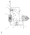
- Fig. 1 a schematic representation of a preferred filter assembly.
- FIG. 1 the construction of a filter system 2 is shown, which operates under fluctuating operating pressure.
- the filter unit 2 is used as a top filter of the transmitting vessel for coal, whereby the filter pressure pF changes during operation.
- the filters should be able to be cleaned both when relaxing the pressure in the sending vessel and when compressing the pressure in the sending vessel.
- the purge pressure pT is carried along with the filter pressure pF.
- the filter unit 2 is equipped with filter bags and a Pulse-Jet cleaning system, which cleans the filter bags either differential pressure-dependent or cyclically.
- a cleaning pressure pT is provided for cleaning the filter, which is above the operating pressure pF (which is also referred to as filter pressure pF) of the pressure filter 4. If the cleaning pressure pT of the filter system 2 is too low compared with the filter pressure pF, the filter cake can not be completely or completely detached from the tube filters. For cleaning, the cleaning medium is therefore provided with an overpressure relative to the filter pressure pF. Is the overpressure of Filter system 2 too high, this can result in extreme cases destroying the filter bags. As a rule, too much overpressure shortens the service life of the filter bags. As a result, it will be ensured that the overpressure of the purge pressure pT with respect to the filter pressure pF is within a certain pressure range.
- the filter system in Fig.1 has a pressure filter 4 for filtering the dirt.
- the air to be filtered is passed from outside to inside through the filter bags to be cleaned.
- a cleaning medium for cleaning the bag filter both air, nitrogen and another inert gas can be used.
- compressed air is used to clean the filter.
- the compressed air is provided at a feed pressure PN at the compressed air supply 6.
- the feed pressure pN is selected to exceed the purge pressure pT of the purge medium in the purge tank 8.
- the compressed air supply has a first differential pressure regulator 10, which is arranged between the cleaning tank 8 and the compressed air feed 6 and regulates a fluid flow between the compressed air feed 6 and the cleaning tank 8.
- the discharge line 7 from the cleaning tank 8 to the pressure filter 4 has a second differential pressure regulator 12, which discharges compressed air from the cleaning tank 8 via the pressure filter 4 or the pressure filter line 9 when an upper pressure difference between the cleaning tank 8 and the pressure filter 4 is exceeded.
- the pressure filter line 9 carries only clean gas, which it is mounted on the clean side of the pressure filter.
- the first differential pressure regulator 10 has a first control unit 14, which controls the opening and closing of the first differential pressure regulator 10. Opening the first differential pressure regulator 10 fills the cleaning tank 8 with the cleaning medium, which leads to an increase of the cleaning pressure pT in the cleaning tank 8. Closing of the first differential pressure regulator 10 results in no fluid connection between the cleaning tank 8 and the compressed air supply 6. At rest, the first differential pressure regulator 10 is opened to ensure that the Abcuristank 8 is supplied with air and in the control units 14, 16, a first air pressure is provided. The second differential pressure regulator 12 is closed to allow a filling of the Abcuristanks 8 from the idle state out.
- the second differential pressure regulator 12 has a second control unit 16, which controls the opening and closing of the second differential pressure regulator 12.
- An opening of the second differential pressure regulator 12 leads air from the Abcuristank 8 preferably through the discharge line 7 into the pressure filter 4 and thus reduces the Abthesestik in Abcuristank 8.
- the second differential pressure regulator 12 is preferably designed so that it is closed in the idle state. This results in the advantage that in case of failure of the pressure filter 4 is not acted upon with a high Abthesestik.
- the two control units 14, 16 each have a first pressure chamber 18, 20 and a second pressure chamber 24, 26, which control the differential pressure regulator 10, 12. Depending on the applied pressure difference and the springs 34, 36, the differential pressure regulator 10, 12 either closed or opened.
- the differential pressure controllers 10, 12 are set so that they can only assume two states.
- the first control unit 14 has a first positive pressure chamber 18 and a first negative pressure chamber 20, which are connected to each other via a first flexible membrane 22.
- the second control unit 16 has a second positive pressure chamber 24 and a second negative pressure chamber 26, which are connected to each other via a second flexible membrane 28.
- the first positive pressure chamber 18 is fluidly connected to the second positive pressure chamber 24 and the Abcuristank 8 via the positive effective line 30. In the cleaning tank 8, in the first positive pressure chamber 18 and the second positive pressure chamber 24 is thus the same pressure. As a result, the pressure in the positive reaction line 30 corresponds to the purge pressure.
- the first negative pressure chamber 20 is fluidly connected to the second negative pressure chamber 26 and the pressure filter 4 via a negative effective line 32.
- the pressure in the negative effective line 32 corresponds to the filter pressure.
- the positive and the negative effective lines 30, 32 are designed so that a fluid is conducted in the active lines.
- the fluid in the effective lines 30, 32 corresponds to the fluid in the cleaning tank 8 and the pressure filter 4.
- the positive effective line 30 has an opening in the cleaning tank 8 through which the pressure equalization between the positive effective line 30 and the cleaning tank 8 is controlled.
- the negative effective line 32 has an opening in the pressure filter 4, via which the pressure equalization between the negative effective line and the cleaning tank is regulated.
- the effective lines 30, 32 are fluid-connected and only for the pressure equalization between Abcuristank, first control unit 14 (pressure chamber 18) and second control unit 16 (pressure chamber 24) or pressure filter 4 with first control unit 14 (pressure chamber 20) and second control unit 16 (pressure chamber 26 ), these active lines 30, 32 can be selected with a relatively small cross-section. Preferably, a 1/8 inch (9.73 mm) section is used for the active lines 30, 32.
- the control loop which controls the purge pressure pT comprises the positive and negative effective lines 30, 32, the first control unit 14 and the second control unit 16, and the first and second differential pressure regulators 10, 12.
- a first spring 34 is disposed in the first negative pressure chamber 20 and a second spring 36 is disposed in the second negative pressure chamber 26. Both springs 34, 36 are used to set the threshold at which the differential pressure regulator 10, 12 open or close and can be adjusted so that the pressure of Abcuristik over the filter pressure can be set.
- the first spring 34 exerts a first spring pressure on the first diaphragm.
- the second spring 36 acts depending on the setting of the second biasing means a second spring pressure on the second membrane.
- the first differential pressure regulator 10 switches as a function of the pressure difference between the first positive pressure chamber 18, the first negative pressure chamber 20 and the first spring pressure applied to the first diaphragm 22.
- the second differential pressure regulator 12 switches as a function of the pressure difference between the second positive pressure chamber 24, the second negative pressure chamber 26 and the spring pressure applied to the second diaphragm 28.
- the control circuit is set so that the purge pressure pT at any time by a predetermined pressure over the filter pressure pF to clean the pressure filter 4 with the Abtheses Kunststoff effectively.
- the amount is determined by setting a lower pressure difference and an upper pressure difference.
- the lower pressure difference is the amount of the least overpressure that the Abcuristank 8 is to provide against the pressure filter 4. If the purge pressure with respect to the filter pressure pF is in the predetermined range between the upper and the lower pressure difference, then the first differential pressure regulator 10 and the second differential pressure regulator 12 remain closed.
- the first differential pressure regulator 10 is opened to increase the purge pressure pT in the purge tank 8. If the filter pressure pF decreases so that the pressure difference between the filter pressure and the purge pressure is above the upper pressure difference, the second differential pressure regulator 12 is opened to reduce the purge pressure by discharging the compressed air via the drain line 7.
- the upper and the lower pressure difference are adjusted by springs 34, 36 in the control unit 14, 16.
- the first spring 34 is disposed in the first negative pressure chamber 20 of the first control unit 14 and exerts a pressure on the diaphragm 22 of the first negative pressure chamber 20.
- the lower pressure difference can be adjusted. If the pressure ratio between the first positive pressure chamber 18 and the first negative pressure chamber 20 is below the threshold value, the first differential pressure regulator 10 opens. As a result, the cleansing tank 8 is fed by the gas supply 6 until the pressure difference lies between the upper and the lower pressure difference.
- the second spring 36 is disposed in the second negative pressure chamber 26 of the second differential pressure regulator 12 and exerts a pressure on the second diaphragm 28.
- Such a fluid-conducting control circuit ensures that the cleaning pressure pT in the cleaning tank 8 at all times is above the filter pressure pF in the pressure filter 4, regardless of whether the filter pressure pF increases or decreases.
- the filter system does not serve to trigger the actual cleaning process.
- an air stream from the cleaning tank 8 via one or more pipe (not shown) in the blow tubes of the pressure filter 4 is passed (not shown).
- the actual cleaning process is controlled by valves, preferably diaphragm valves (not shown), which are arranged between the cleaning tank and the pressure filter and clean by opening the bag filters.
- the control is explained below with reference to 3 different phases, each with a different filter pressure pF.
- the filter bags are optimally cleaned at an overpressure between 4 and 5 bar.
- the first differential pressure regulator 10 is therefore set so that it opens at a first pressure difference less than 4 bar.
- the second differential pressure regulator 12 is set so that it opens from a pressure difference of 5 bar.
- the pressure in the positive effective line 30, in the first positive pressure chamber 18 and in the second positive pressure chamber 24 is also 14.5 bar.
- the pressure in the negative effective line 32, in the first negative pressure chamber 20 and the second negative pressure chamber 26 is also 10 bar.
- both in the first control unit 14 and in the second control unit 16 is a pressure difference of 4.5 bar.
- the pressure difference corresponds to the overpressure of Abthesestiks compared to the filter pressure.
- the pressure difference of 4.5 bar is in the range in which the bag filters are optimally cleaned.
- both the first differential pressure regulator 10 and the second differential pressure regulator 12 remain closed.
- the overpressure in the cleaning tank 8 is thus 2.5 bar and is thus too low to allow efficient cleaning of the filter bags. Therefore, the first differential pressure regulator 10 opens and the cleaning tank 8 is filled with purge air to increase the purge pressure in the purge tank 8.
- the first differential pressure regulator 10 remains open until the pressure difference between the cleaning tank 8 and the pressure filter 4 is again 4 bar.
- the second differential pressure regulator 12 remains closed due to the pressure difference of 2.5 bar.
- the filter system 2 is thus self-regulating. As soon as the filter pressure changes, so that a predetermined pressure difference between the filter pressure and Abcuristik is no longer met, the Abgenesisstik is tracked by the interaction of the two differential pressure regulator 10, 12 that the required pressure is ensured.
- the cleaning pressure is also tracked when the pressure in the cleaning tank 8 changes. This always happens when compressed air for cleaning is removed from the cleaning tank (fittings and pipes for cleaning are not shown here). As a result of this removal, the pressure in the cleaning tank 8 drops, as a result of which the pressure difference between the cleaning tank 8 and the pressure filter 4 also drops, consequently the differential pressure regulator 10 opens until the pressure difference is 4 bar again.
- two flow rate limiter can be arranged in the effective lines 30, 32, which limit the maximum volume flow which flows through the effective lines 30, 32.
- the positive flow restrictors 38, 39 are disposed in the positive working line 30, and the negative flow restrictors 40, 41 are disposed in the negative working line 32.
Abstract
Erfindungsgemäß weist die Filteranlage eine Gasspeisung (Druckluftspeisung) auf, welche die Filteranlage mit einem Abreinigungsmedium mit einem Speisedruck pN versorgt. Die Filteranlage weist auch einen Abreinigungstank auf, der von der Gasspeisung gespeist wird und in dem das Abreinigungsmedium mit einem Abreinigungsdruck pT gespeichert ist. Des Weiteren weist die Filteranlage auch einen Druckfilter mit einem Filterdruck pF auf. Der Druckfilter wird zyklisch in vorbestimmten Zeitabständen oder differenzdruckabhängig von dem Abreinigungsmedium aus dem Abreinigungstank gereinigt.According to the invention, the filter system has a gas feed (compressed air feed) which supplies the filter system with a cleaning medium with a feed pressure pN. The filter unit also has a cleaning tank, which is fed by the gas supply and in which the cleaning medium is stored with a cleaning pressure pT. Furthermore, the filter system also has a pressure filter with a filter pressure pF. The pressure filter is cyclically cleaned at predetermined time intervals or differential pressure-dependent from the cleaning medium from the Abreinigungstank.
Description
Die vorliegende Erfindung betrifft allgemein eine Filteranlage mit einer selbstregelnden Abreinigung. Die Erfindung ist besonders zur Reinigung einer Filteranlage geeignet, welche zur Reinigung von Sendegefäßen im Bereich der Kohlenstaubeinblasung eingesetzt wird. In den Sendegefäßen wird Kohlestaub mit Stickstoff auf einen vorbestimmten Druck komprimiert. Ist der vorbestimmte Druck erreicht, so wird der Kohlestaub mit dem Stickstoff pneumatisch aus dem Sendegefäß befördert bis im Sendegefäß nicht mehr ausreichend Kohlestaub vorhanden ist. Zum Nachladen des Sendegefäßes wird der Druck des Sendegefäßes an den Umgebungsdruck angepasst. Beim Entspannen darf der restliche Kohlestaub im Sendegefäß jedoch nicht in die Atmosphäre gelangen. Deshalb wird die beim Entspannen abgelassene Luft in eine Filteranlage umgeleitet in der mehrere Filterschläuche angeordnet sind. Die verstaubten Filterschläuche können mit einer erfindungsgemäßen Abreinigung während der Entspannung gereinigt werden.The present invention generally relates to a filter system with a self-regulating cleaning. The invention is particularly suitable for cleaning a filter system, which is used for cleaning of transmission vessels in the field of coal dust injection. In the sending vessels coal dust is compressed with nitrogen to a predetermined pressure. If the predetermined pressure is reached, the coal dust is pneumatically transported with the nitrogen from the sending vessel until no longer sufficient coal dust is present in the sending vessel. To reload the transmitter vessel, the pressure of the transmitter vessel is adjusted to the ambient pressure. When decompressing the remaining coal dust in the sending vessel may not reach the atmosphere. Therefore, the deflated air is redirected to a filter system in which several filter bags are arranged. The dusty filter bags can be cleaned with a cleaning according to the invention during the relaxation.
Aus dem Stand der Technik gehen unterschiedliche Abreinigungssysteme für Filteranlagen hervor, welche eine Reinigung von verschmutzten Filtern ermöglichen. Filteranlagen werden in zahlreichen industriellen Prozessen angewandt und dienen grundsätzlich zum Reinigen/Entstauben eines Fluidstroms, welcher durch solche Filteranlagen geleitet wird. Im Inneren weisen die Filteranlagen meistens mehrere Filterschläuche auf, welche das durchströmende Fluid von Verunreinigungen, wie beispielsweise Staubpartikel, befreien. In den meisten Fällen wird der Fluidstrom von außen nach innen durch die Filterschläuche geleitet, so dass sich die Verunreinigungen an der Außenseite der Filterschläuche absetzen. Nach einer gewissen Betriebszeit sind die Filterschläuche verschmutzt und müssen gereinigt werden.From the prior art different cleaning systems for filter systems show that allow a cleaning of dirty filters. Filter systems are used in numerous industrial processes and are basically used for cleaning / dedusting a fluid flow, which is passed through such filter systems. Inside, the filter systems usually have a plurality of filter bags, which free the fluid flowing through of impurities, such as dust particles. In most cases, the fluid flow from outside to inside is passed through the filter bags, so that the contaminants settle on the outside of the filter bags. After a certain period of operation, the filter bags are dirty and must be cleaned.
Anfangs wurden die Filter durch Rütteln oder Klopfen durch motorisch oder manuell bediente Rüttelvorrichtungen abgereinigt. Mit Hilfe solcher Verfahren werden die Filterschläuche in Schwingung versetzt und der Filterkuchen löst sich aufgrund dieser Bewegungen von der Außenfläche der Filter. Die mechanische Abreinigung hat jedoch eine hohe Beanspruchung der Filterschläuche zur Folge, weshalb sich deren Standzeit verkürzt.Initially, the filters were cleaned by shaking or tapping by motorized or manually operated vibrators. With the help of such methods, the filter bags are set in vibration and the filter cake dissolves due to these movements of the outer surface of the filter. However, the mechanical cleaning has a high stress on the filter tubing result, which is why their life shortened.
Um die Beanspruchung der Filterschläuche zu reduzieren, ist man auf eine Abreinigung der Filterschläuche mit einem Luftstrom übergegangen, welcher gegenüber dem Filterdruck mit einem Überdruck bereitgestellt wird. Besonders Abreinigungsströme, welche gepulst auf die Filterschläuche aufgebracht werden, eignen sich besonders um die Filterschläuche effizient zu reinigen. Deshalb werden Filterschläuche heutzutage vorwiegend mit dem "Pulse-Jet"-Verfahren abgereinigt. Bei solch einem Verfahren wird das Abreinigungsmedium von innen nach außen (in Gegenstromrichtung zum Fluidstrom) durch die Filterschläuche geleitet, wodurch der Filterkuchen von der Außenfläche der Filterschläuche gelöst und in einem Staubsammelbehälter aufgefangen wird. Die ersten "Pulse-Jet"-Verfahren beaufschlagten die Schlauchfilter mit einem gepulstenen Abreinigungsstrom mit einem konstanten Abreinigungsdruck. Es hat sich jedoch gezeigt, dass keine "effektive" Abreinigung der Filterschläuche möglich ist, falls der Abreinigungsdruck nicht an den Filterdruck angepasst wird.In order to reduce the stress on the filter bags, it has gone over to a cleaning of the filter bags with an air flow, which is provided opposite the filter pressure with an overpressure. Especially cleaning streams, which are pulsed on the filter hoses, are particularly suitable for efficient cleaning of the filter hoses. Therefore, filter bags are cleaned today mainly with the "pulse jet" method. In such a process, the scrubbing medium is directed from the inside to the outside (countercurrent to the fluid flow) through the filter bags, whereby the filter cake is released from the outer surface of the filter bags and collected in a dust collection container. The first "Pulse-Jet" processes impinged on the bag filters with a pulsed purge stream at a constant purge pressure. However, it has been shown that no "effective" cleaning of the filter bags is possible if the cleaning pressure is not adapted to the filter pressure.
Zum Durchführen der Abreinigung wird sichergestellt, dass der Impuls, welcher von der Abreinigungsluft auf die Schlauchfilter aufgebracht wird die Schlauchfilter nicht zu stark beansprucht. Entscheidend dabei ist der Überdruck mit dem das Abreinigungsmedium bereitgestellt wird. Wird der Überdruck des Abreinigungsdruck gegenüber dem Filterdruck zu hoch gewählt, so wird die Standzeit der Schlauchfilter reduziert. Im schlimmsten Fall kann sogar der Schlauchfilter durch einen zu hohen Überdruck zerstört werden. Für den Fall, dass der Überdruck jedoch nicht ausreichend hoch gewählt wurde, wird der Schlauchfilter nicht effizient abgereinigt. Demzufolge wird der Abreinigungsdruck so reguliert, dass er gegenüber dem Filterdruck in einem vorbestimmten Bereich liegt, sodass der Abreinigungsdruck ausreicht um den Schlauchfilter effektiv und schonend zu reinigen.To carry out the cleaning, it is ensured that the impulse, which is applied by the cleaning air to the bag filters, does not stress the bag filters too much. Crucial here is the overpressure with which the Abreinigungsmedium is provided. If the overpressure of the cleaning pressure is selected too high compared with the filter pressure, the service life of the bag filter is reduced. In the worst case, even the bag filter can be destroyed by too high pressure. However, if the overpressure is not selected to be sufficiently high, the bag filter will not be efficiently cleaned. As a result, the purge pressure is regulated to be within a predetermined range from the filter pressure, so that the purge pressure is sufficient to effectively and gently clean the bag filter.
Das
Die Drucksensoren auf der "schmutzigen Seite" des Schlauchfilters sind jedoch ständig Verunreinigungen ausgesetzt, weshalb eine zuverlässige Erfassung des Differenzdrucks problematisch ist. Da es sich bei der Filterabreinigung um einen hoch automatisierten Prozess handelt, kann das Fehlverhalten von einem der beiden Drucksensoren nur schwer von "außen" festgestellt werden. Somit wird ein Fehlverhalten, wenn überhaupt, erst bemerkt, wenn es schon zu spät ist, d.h. wenn die Filterschläuche entweder frühzeitig gerissen sind, oder wenn die Filterschläuche so verstopft sind, dass es in der Filteranlage zu einem erhöhten Druckverlust kommt.However, the pressure sensors on the "dirty side" of the bag filter are constantly exposed to contamination, so that a reliable detection of the differential pressure is problematic. Since filter cleaning is a highly automated process, the malfunction of one of the two pressure sensors is difficult to determine from the outside. Thus, misbehavior, if any, is only noticed when it is already too late, i. if the filter hoses are either cracked prematurely or if the filter hoses are so clogged that there is an increased pressure loss in the filter system.
Des Weiteren, steuert die Anlage die Abreinigung über die Differenzdrücke und nicht über die Absolutdrücke. Steigt der Filterdruck beispielsweise durch externe Einflüsse an, kann der Schlauchfilter nicht mehr gereinigt werden, da der benötigte Abreinigungsdruck nicht mehr bereitgestellt werden kann.Furthermore, the system controls the cleaning via the differential pressures and not the absolute pressures. If the filter pressure increases, for example due to external influences, the bag filter can no longer be cleaned because the required cleaning pressure can no longer be provided.
Eine Aufgabe der vorliegenden Erfindung ist es, eine Filteranlage bereitzustellen, welche eine zuverlässige Bereitstellung eines Abreinigungsdrucks pT zur Abreinigung der Filterschläuche bei einem variablem Filterdruck ermöglicht. Diese Aufgabe wird durch eine Abreinigungsanlage nach Anspruch 1 gelöst.An object of the present invention is to provide a filter system which enables reliable provision of a purge pressure pT for cleaning the filter bags at a variable filter pressure. This object is achieved by a cleaning system according to claim 1.
Erfindungsgemäß umfasst die Filteranlage eine Gasspeisung, wobei es sich bei einer bevorzugten Ausgestaltung der Erfindung um eine Druckluftspeisung handelt, welche die Filteranlage mit einem Abreinigungsmedium mit einem konstanten Speisedruck pN versorgt. Des Weiteren umfasst die Filteranlage einen Abreinigungstank, der von der Gasspeisung gespeist wird und in dem das Abreinigungsmedium mit einem variablen Abreinigungsdruck pT gespeichert ist wobei pN ≥ pT ist. Die Filteranlage umfasst auch einen Druckfilter mit einem Filterdruck pF. Der Druckfilter wird zyklisch in vorbestimmten Zeitabständen oder differenzdruckabhängig von dem Abreinigungsmedium aus dem Abreinigungstank abgereinigt. Zusätzlich weist die Filteranlage einen Regelkreis auf, welcher einen ersten Differenzdruckregler und eine erste Regeleinheit umfasst. Der erste Differenzdruckregler ist zwischen der Gasspeisung und dem Abreinigungstank angeordnet. Die erste Regeleinheit betätigt den ersten Differenzdruckregler bei einer unteren Druckdifferenz. Des Weiteren umfasst der Regelkreis einen zweiten Differenzdruckregler und eine zweite Regeleinheit. Der zweite Differenzdruckregler ist in der Ablassleitung des Abreinigungstanks angeordnet. Die Ablassleitung ist bevorzugt zwischen dem Abreinigungstank und dem Druckfilter angeordnet. Die zweite Regeleinheit betätigt den zweiten Differenzdruckregler bei einer oberen Druckdifferenz. Die Regeleinheit umfasst auch eine positive Wirkleitung und eine negative Wirkleitung. Die positive Wirkleitung fluidverbindet die erste Regeleinheit mit der zweiten Regeleinheit und dem Abreinigungstank. Die negative Wirkleitung fluidverbindet die erste Regeleinheit mit der zweiten Regeleinheit und dem Druckfilter. Im Betrieb wird der Abreinigungsdrucks pT mit einem Überdruck gegenüber dem Filterdruck pN im Abreinigungstank bereitgestellt wird und an der erste Regeleinheit und der zweiten Regeleinheit anliegt. Die erste Regeleinheit betätigt den ersten Differenzdruckregler wenn der Überdruck unter der unteren Druckdifferenz liegt. Die zweite Regeleinheit betätigt den zweiten Differenzdruckregler, wenn der Überdruck über der oberen Druckdifferenz liegt.According to the invention, the filter system comprises a gas feed, wherein in a preferred embodiment of the invention is a compressed air supply, which supplies the filter system with a cleaning medium with a constant feed pressure pN. Furthermore, the filter system comprises a cleaning tank, which is fed by the gas supply and in which the cleaning medium is stored with a variable cleaning pressure pT, where pN ≥ pT. The filter system also includes a pressure filter with a filter pressure pF. The pressure filter is cleaned cyclically at predetermined time intervals or differential pressure-dependent from the cleaning medium from the cleaning tank. In addition, the filter system has a control loop which comprises a first differential pressure regulator and a first control unit. The first differential pressure regulator is disposed between the gas supply and the purge tank. The first control unit actuates the first differential pressure controller at a lower pressure difference. Furthermore, the control circuit comprises a second differential pressure regulator and a second control unit. The second differential pressure regulator is arranged in the discharge line of the cleaning tank. The discharge line is preferably arranged between the cleaning tank and the pressure filter. The second control unit actuates the second differential pressure regulator at an upper pressure difference. The control unit also includes a positive conduction and a negative conduction. The positive conduction fluid connects the first control unit with the second control unit and the Abreinigungstank. The negative effective line fluid connects the first control unit with the second control unit and the pressure filter. In operation, the purge pressure pT is provided with an overpressure relative to the filter pressure pN in the purge tank and is applied to the first control unit and the second control unit. The first control unit actuates the first differential pressure regulator when the overpressure is below the lower pressure differential. The second control unit actuates the second differential pressure regulator when the overpressure is above the upper pressure differential.
Infolgedessen ist sichergestellt, dass der Druckfilter beim Abreinigen mit einem Abreinigungsdruck pT beaufschlagt wird, der ein effektives und schonendes Reinigen der Filteranlage ermöglicht ohne dass der Druck gemessen wird. Im Betrieb stellt die Filteranlage den geeigneten Abreinigungsdruck zu jeder Zeit bereit, ohne dass sich auch nur ein Sensor im Druckfilter befindet. Auch bei einer Variation des Filterdrucks pF regelt die Filteranlage zuverlässig nach und passt den Abreinigungsdruck pT so an, dass eine zuverlässige Filterreinigung gewährleistet ist.As a result, it is ensured that the pressure filter is subjected during cleaning with a cleaning pressure pT, which allows effective and gentle cleaning of the filter system without the pressure is measured. in the Operation, the filter system provides the appropriate Abreinigungsdruck at any time, without even a sensor is in the pressure filter. Even with a variation of the filter pressure pF, the filter system reliably regulates and adapts the cleaning pressure pT so that a reliable filter cleaning is guaranteed.
Bei der Abreinigungsvorrichtung im Patent
Die erfindungsgemäße Filteranlage ist durch die Fluidverbindung zwischen den Regeleinheiten besonders zuverlässig und von äußeren Einflüssen unabhängig. Gerade in diesem Einsatzbereich, wo viele Verunreinigungen geradezu "gesammelt" werden Falschmessungen, Störungen und Versagen von Sensoren geradezu provoziert. Da bei der erfindungsgemäßen Filteranlage keine Sensoren benötigt werden, um ein Selbstregeln des Abreinigungsdrucks gegenüber dem Filterdruck zu gewährleisten, ist die erfindungsgemäße Filteranlage besonders zuverlässig.The filter system according to the invention is particularly reliable and independent of external influences due to the fluid connection between the control units. Especially in this field of application, where many impurities are virtually "collected" false measurements, disturbances and failure of sensors almost provoked. Since in the filter system according to the invention no sensors are needed to ensure a self-regulation of Abreinigungsdrucks compared to the filter pressure, the filter system according to the invention is particularly reliable.
Die erfindungsgemäße Filteranlage stellt sicher, dass bei fluktuierendem Betriebsdruck pF (Filterdruck) stets ein vorbestimmter Überdruck zwischen dem Druckfilter und dem Abreinigungstank gewährleistet ist. Beim Abfallen oder Ansteigen des Filterdrucks pF wird der Abreinigungsdruck im Abreinigungstank von der Regeleinheit nachgeregelt, sodass die Druckdifferenz zwischen dem Abreinigungstank und dem Druckfilter in dem vorbestimmten Druckbereich liegt.The filter system according to the invention ensures that a fluctuating operating pressure pF (filter pressure) always ensures a predetermined overpressure between the pressure filter and the cleaning tank. When the filter pressure pF falls or rises, the purge pressure in the purge tank is readjusted by the control unit, so that the pressure difference between the purge tank and the pressure filter is in the predetermined pressure range.
Nach einer bevorzugten Ausgestaltung der Erfindung umfasst die erste Regeleinheit eine erste Feder mit der die untere Druckdifferenz eingestellt werden kann. Vorzugsweise ist in der ersten Regeleinheit eine erste Membran angeordnet, welche eine erste positive Druckkammer von einer ersten negativen Druckkammer trennt. Die erste Feder kann durch eine erste Vorspanneinrichtung so eingestellt werden, dass die erste Feder einen ersten Federdruck auf die erste Membran ausübt. Des Weiteren kann die zweite Regeleinheit eine zweite Feder umfassen mit der die obere Druckdifferenz eingestellt werden kann. Bevorzugt ist in der zweiten Regeleinheit eine zweite Membran angeordnet, welche eine zweite positive Druckkammer von einer zweiten negativen Druckkammer trennt. Die zweite Feder kann durch eine zweite Vorspanneinrichtung so eingesellt werden, dass die zweite Feder einen zweiten Federdruck auf die zweite Membran ausübt. Die erste Vorspanneinrichtung und die zweite Vorspanneinrichtung können manuell eingestellt oder elektronisch gesteuert werden. Die erste Feder und die zweite Feder ermöglichen eine Anpassung der ersten und der zweiten Druckdifferenz. Somit kann der Bereich des Überdrucks mit dem der Abreinigungsdruck gegenüber dem Druckfilter bereitgestellt werden soll eingestellt werden.According to a preferred embodiment of the invention, the first control unit comprises a first spring with which the lower pressure difference can be adjusted. Preferably, in the first control unit, a first diaphragm is arranged, which separates a first positive pressure chamber from a first negative pressure chamber. The first spring may be adjusted by a first biasing means so that the first spring exerts a first spring pressure on the first diaphragm. Furthermore, the second control unit may comprise a second spring with which the upper pressure difference can be adjusted. Preferably, a second membrane is arranged in the second control unit, which separates a second positive pressure chamber from a second negative pressure chamber. The second spring may be locked by a second biasing means so that the second spring exerts a second spring pressure on the second diaphragm. The first biasing means and the second biasing means may be manually adjusted or electronically controlled. The first spring and the second spring allow adjustment of the first and the second pressure difference. Thus, the range of the overpressure with which the purge pressure is to be provided opposite to the pressure filter can be adjusted.
Bevorzugt ist der erste Differenzdruckregler mit der ersten Regeleinheit mechanisch gekoppelt und/oder der zweite Differenzdruckregler ist mit der zweiten Regeleinheit mechanisch gekoppelt. Dies ermöglicht eine besonders zuverlässige Steuerung der ersten Druckdifferenz und der zweiten Druckdifferenz. Sogar bei Stromausfall können die Differenzdruckregler die erste Druckdifferenz und/oder die zweite Druckdifferenz steuern.Preferably, the first differential pressure regulator is mechanically coupled to the first control unit and / or the second differential pressure regulator is mechanically coupled to the second control unit. This allows a particularly reliable control of the first pressure difference and the second pressure difference. Even in the event of a power failure, the differential pressure controllers can control the first pressure difference and / or the second pressure difference.
Alternativ kann der erste Differenzdruckregler mit der ersten Regeleinheit elektronisch gekoppelt sein und/oder der zweite Differenzdruckregler kann mit der zweiten Regeleinheit elektronisch gekoppelt sein. Daraus ergibt sich der Vorteil, dass die Regeleinheiten nicht in unmittelbarer Nähe zu den Differenzdruckreglern angeordnet sein müssen.Alternatively, the first differential pressure regulator may be electronically coupled to the first control unit and / or the second differential pressure regulator may be electronically coupled to the second control unit. This results in the advantage that the control units do not have to be arranged in the immediate vicinity of the differential pressure regulators.
Bevorzugt ist der erste Differenzdruckregler im Ruhezustand geöffnet und der zweite Differenzdruckregler im Ruhezustand geschlossen. Somit ist ein Füllen des Abreinigungstanks mit Abreinigungsluft aus dem Ruhezustand möglich.The first differential pressure regulator is preferably open in the idle state and the second differential pressure regulator is closed in the idle state. Thus, a filling of the Abreinigungstanks with Abreinigungsluft from hibernation is possible.
Nach einer bevorzugten Ausgestaltung der Erfindung umfasst der Regelkreis mindestens einen Durchflussmengenbegrenzer, welcher in der negativen und/oder positiven Wirkleitung angebracht sind. Durch die Durflussmengenbegrenzer in den Wirkleitungen können Überschwinger der Differenzdruckregler vermieden werden.According to a preferred embodiment of the invention, the control circuit comprises at least one flow rate limiter, which are mounted in the negative and / or positive conduction line. By the Durflussmengenbegrenzer in the active lines overshoot the differential pressure regulator can be avoided.
Die Filteranlage wird bevorzugt bei Kohlestaubeinblasanlagen zum Reinigen der Filter von Sendegefäßen verwendet. Sowohl beim Entspannen als auch beim Verdichten des Sendegefäßes sollen die Filter gereinigt werden können. Hierzu wird die erfindungsgemäße Filteranlage verwendet.The filter system is preferably used in Kohlestaubeinblasanlagen for cleaning the filter of transmitting vessels. Both when relaxing and when compressing the transmitter vessel, the filters should be able to be cleaned. For this purpose, the filter system according to the invention is used.
Weitere Einzelheiten und Vorteile der Erfindung können der nachfolgenden ausführlichen Beschreibung einer möglichen Ausführungsform der Erfindung anhand der beiliegenden Figur entnommen werden. Diese zeigt:
In
Die Filteranlage in
Der erste Differenzdruckregler 10 weist eine erste Regeleinheit 14 auf, welche das Öffnen und Schließen des ersten Differenzdruckreglers 10 steuert. Ein Öffnen des ersten Differenzdruckreglers 10 füllt den Abreinigungstank 8 mit dem Abreinigungsmedium, was zu einer Erhöhung des Abreinigungsdrucks pT im Abreinigungstank 8 führt. Ein Schließen des ersten Differenzdruckreglers 10 führt dazu, dass keine Fluidverbindung zwischen dem Abreinigungstank 8 und der Druckluftspeisung 6 besteht. Im Ruhezustand ist der erste Differenzdruckregler 10 geöffnet um zu gewährleisten, dass der Abreinigungstank 8 mit Luft versorgt wird und in den Regeleinheiten 14, 16 ein erster Luftdruck zur Verfügung gestellt wird. Der zweite Differenzdruckregler 12 wird geschlossen um ein Befüllen des Abreinigungstanks 8 aus dem Ruhezustand heraus zu ermöglichen.The first
Der zweite Differenzdruckregler 12 weist eine zweite Regeleinheit 16 auf, welche das Öffnen und Schließen des zweiten Differenzdruckreglers 12 steuert. Ein Öffnen des zweiten Differenzdruckreglers 12 führt Luft aus dem Abreinigungstank 8 bevorzugt durch die Ablassleitung 7 in den Druckfilter 4 ab und erniedrigt somit den Abreinigungsdruck im Abreinigungstank 8. Der zweite Differenzdruckregler 12 ist bevorzugt so ausgelegt, dass er im Ruhezustand geschlossen ist. Daraus ergibt sich der Vorteil, dass bei einem Ausfall der Druckfilter 4 nicht mit einem zu hohen Abreinigungsdruck beaufschlagt wird.The second
Die beiden Regeleinheiten 14, 16 weisen jeweils eine erste Druckkammer 18, 20 und eine zweite Druckkammer 24, 26 auf, welche die Differenzdruckregler 10, 12 steuern. Abhängig von der anliegenden Druckdifferenz und den Federn 34, 36 werden die Differenzdruckregler 10, 12 entweder geschlossen oder geöffnet. Die Differenzdruckregler 10, 12 sind so eingestellt, dass sie nur zwei Zustände annehmen können. Die erste Regeleinheit 14 weist eine erste positive Druckkammer 18 und eine erste negative Druckkammer 20 auf, welche über eine erste flexible Membran 22 miteinander verbunden sind. Die zweite Regeleinheit 16 weist eine zweite positive Druckkammer 24 und eine zweite negative Druckkammer 26 auf, welche über eine zweite flexible Membran 28 miteinander verbunden sind. Die erste positive Druckkammer 18 ist mit der zweiten positiven Druckkammer 24 und dem Abreinigungstank 8 über die positive Wirkleitung 30 fluidverbunden. Im Abreinigungstank 8, in der ersten positiven Druckkammer 18 und der zweiten positiven Druckkammer 24 liegt somit der gleiche Druck an. Demzufolge entspricht der Druck in der positiven Wirkleitung 30 dem Abreinigungsdruck.The two
Die erste negative Druckkammer 20 ist mit der zweiten negativen Druckkammer 26 und dem Druckfilter 4 über eine negative Wirkleitung 32 fluidverbunden. In der ersten negativen Druckkammer 20, in der zweiten negativen Druckkammer 26 und in dem Druckfilter 4 liegt somit der gleiche Druck an. Demzufolge entspricht der Druck in der negativen Wirkleitung 32 dem Filterdruck.The first
Die positiven und die negativen Wirkleitungen 30, 32 sind so ausgelegt, dass ein Fluid in den Wirkleitungen geführt wird. Das Fluid in den Wirkleitungen 30, 32 entspricht dem Fluid im Abreinigungstank 8 und dem Druckfilter 4. Die positive Wirkleitung 30 besitzt eine Öffnung im Abreinigungstank 8 über die der Druckausgleich zwischen der positiven Wirkleitung 30 und dem Abreinigungstank 8 geregelt wird. Die negative Wirkleitung 32 besitzt eine Öffnung im Druckfilter 4, über die der Druckausgleich zwischen der negativen Wirkleitung und dem Abreinigungstank geregelt wird. Da die Wirkleitungen 30, 32 fluidverbunden sind und nur für den Druckausgleich zwischen Abreinigungstank, erster Regeleinheit 14 (Druckkammer 18) und zweiter Regeleinheit 16 (Druckkammer 24) bzw. Druckfilter 4 mit erster Regeleinheit 14 (Druckkammer 20) und zweiter Regeleinheit 16 (Druckkammer 26) sorgen muss, können diese Wirkleitungen 30, 32 mit einem relativ kleinen Querschnitt gewählt werden. Vorzugsweise wird für die Wirkleitungen 30, 32 ein Querschnitt von 1/8 Zoll (9,73 mm) verwendet. Der Regelkreis, welcher den Abreinigungsdruck pT steuert, umfasst die positiven und negativen Wirkleitungen 30, 32, die erste Regeleinheit 14 und die zweite Regeleinheit 16, sowie den ersten und zweiten Differenzdruckregler 10, 12. Um die Einstellbarkeit der ersten Regeleinheit 14 und der zweiten Regeleinheit 16 zu verbessern, ist eine erste Feder 34 in der ersten negativen Druckkammer 20 und eine zweite Feder 36 in der zweiten negativen Druckkammer 26 angeordnet. Beide Federn 34, 36 dienen zum Einstellen des Schwellenwerts, bei dem die Differenzdruckregler 10, 12 öffnen oder schließen und können so eingestellt werden, dass der Überdruck des Abreinigungsdruck gegenüber dem Filterdruck festgelegt werden kann. Die erste Feder 34 wirkt je nach Einstellung der ersten Vorspanneinrichtung einen ersten Federdruck auf die erste Membran aus. Die zweite Feder 36 wirkt je nach Einstellung der zweiten Vorspanneinrichtung einen zweiten Federdruck auf die zweite Membran aus. Der erste Differenzdruckregler 10 schaltet in Abhängigkeit der Druckdifferenz zwischen der ersten positiven Druckkammer 18, der ersten negativen Druckkammer 20 und dem auf die erste Membran 22 aufgebrachten ersten Federdruck. Der zweite Differenzdruckregler 12 schaltet in Abhängigkeit der Druckdifferenz zwischen der zweiten positiven Druckkammer 24, der zweiten negativen Druckkammer 26 und dem auf die zweite Membran 28 aufgebrachten Federdruck.The positive and the negative
Der Regelkreis ist so eingestellt, dass der Abreinigungsdruck pT zu jeder Zeit um mit einem vorbestimmten Überdruck gegenüber dem Filterdruck pF, um den Druckfilter 4 mit der Abreinigungsluft effektiv reinigen zu können. Der Betrag wird durch Festlegen einer unteren Druckdifferenz und einer oberen Druckdifferenz bestimmt. Die untere Druckdifferenz ist der Betrag des geringsten Überdrucks, den der Abreinigungstank 8 gegenüber dem Druckfilter 4 bereitstellen soll. Liegt der Abreinigungsdruck gegenüber dem Filterdruck pF im vorbestimmten Bereich zwischen der oberen und der unteren Druckdifferenz, so bleibt der erste Differenzdruckregler 10 und der zweite Differenzdruckregler 12 geschlossen. Steigt der Filterdruck pF an, so dass die Druckdifferenz zwischen dem Filterdruck pF und dem Abreinigungsdruck pT unter der unteren Druckdifferenz liegt, so wird der erste Differenzdruckregler 10 geöffnet um den Abreinigungsdruck pT im Abreinigungstank 8 zu erhöhen. Sinkt der Filterdruck pF, so dass die Druckdifferenz zwischen dem Filterdruck und dem Abreinigungsdruck über der oberen Druckdifferenz liegt, so wird der zweite Differenzdruckregler 12 geöffnet, um den Abreinigungsdruck durch Ablassen der Druckluft über die Ablassleitung 7 zu verringern.The control circuit is set so that the purge pressure pT at any time by a predetermined pressure over the filter pressure pF to clean the pressure filter 4 with the Abreinigungsluft effectively. The amount is determined by setting a lower pressure difference and an upper pressure difference. The lower pressure difference is the amount of the least overpressure that the Abreinigungstank 8 is to provide against the pressure filter 4. If the purge pressure with respect to the filter pressure pF is in the predetermined range between the upper and the lower pressure difference, then the first
Die obere und die untere Druckdifferenz werden durch Federn 34, 36 in der Regeleinheit 14, 16 eingestellt. Die erste Feder 34 ist in der ersten negativen Druckkammer 20 der ersten Regeleinheit 14 angeordnet und übt einen Druck auf die Membran 22 der ersten negativen Druckkammer 20 aus. An der ersten Regeleinheit 10 kann die untere Druckdifferenz eingestellt werden. Liegt das Druckverhältnis zwischen der ersten positiven Druckkammer 18 und der ersten negativen Druckkammer 20 unter dem Schwellwert, öffnet der erste Differenzdruckregler 10. Infolgedessen wird der Abreinigungstank 8 von der Gasspeisung 6 gespeist bis die Druckdifferenz zwischen der oberen und der unteren Druckdifferenz liegt. Die zweite Feder 36 ist in der zweiten negativen Druckkammer 26 des zweiten Differenzdruckreglers 12 angeordnet und wirkt einen Druck auf die zweite Membran 28 aus. Liegt das Druckverhältnis zwischen der zweiten positiven Druckkammer 24 und der zweiten negativen Druckkammer 26 über der oberen Druckdifferenz, öffnet der zweite Differenzdruckregler 12. Infolgedessen wird die Druckluft im Abreinigungstank 8 über die Ablassleitung 7 in den Druckfilter 4 abgelassen. Der zweite Differenzdruckregler 12 bleibt solange geschlossen wie der Überdruck nicht über der oberen Druckdifferenz liegt.The upper and the lower pressure difference are adjusted by
Durch solch einen fluidführenden Regelkreis ist gewährleistet, dass der Abreinigungsdruck pT im Abreinigungstank 8 zu jeder Zeit in einem bestimmten Betrag über dem Filterdruck pF im Druckfilter 4 liegt, unabhängig davon ob der Filterdruck pF steigt oder sinkt. Es soll jedoch kurz erwähnt werden, dass die Filteranlage nicht zum Auslösen des eigentlichen Abreinigungsvorgangs dient. Zur Abreinigung wird ein Luftstrom aus dem Abreinigungstank 8 über eine oder mehrere Rohrleitung (nicht abgebildet) in die Blasrohre des Druckfilters 4 geleitet (nicht abgebildet). Der eigentliche Abreinigungsvorgang wird durch Ventile, bevorzugt Membranventile (nicht abgebildet) gesteuert, welche zwischen dem Abreinigungstank und dem Druckfilter angeordnet sind und durch Öffnen die Schlauchfilter abreinigen.Such a fluid-conducting control circuit ensures that the cleaning pressure pT in the cleaning tank 8 at all times is above the filter pressure pF in the pressure filter 4, regardless of whether the filter pressure pF increases or decreases. However, it should be briefly mentioned that the filter system does not serve to trigger the actual cleaning process. For cleaning, an air stream from the cleaning tank 8 via one or more pipe (not shown) in the blow tubes of the pressure filter 4 is passed (not shown). The actual cleaning process is controlled by valves, preferably diaphragm valves (not shown), which are arranged between the cleaning tank and the pressure filter and clean by opening the bag filters.
Die Reglung wird im Folgenden anhand 3 verschiedener Phasen mit jeweils einem unterschiedlichen Filterdruck pF erläutert. Bei diesem besonders bevorzugten Beispiel, werden die Filterschläuche bei einem Überdruck zwischen 4 und 5 bar optimal gereinigt. Der erste Differenzdruckregler 10 ist deshalb so eingestellt, dass er bei einer ersten Druckdifferenz kleiner als 4 bar öffnet. Der zweite Differenzdruckregler 12 ist so eingestellt, dass er ab einer Druckdifferenz von 5 bar öffnet.The control is explained below with reference to 3 different phases, each with a different filter pressure pF. In this particularly preferred example, the filter bags are optimally cleaned at an overpressure between 4 and 5 bar. The first
In einer erste Phase liegt der Speisedruck bei pN = 20 bar, der Filterdruck liegt bei pF = 10 bar und der Abreinigungsdruck liegt bei pT = 14,5 bar. Durch die Fluidverbindung mit dem Abreinigungstank 8, beträgt der Druck in der positiven Wirkleitung 30, in der ersten positiven Druckkammer 18 und in der zweiten positiven Druckkammer 24 ebenfalls 14,5 bar. Durch die Fluidverbindung mit dem Druckfilter 4 , beträgt der Druck in der negativen Wirkleitung 32, in der ersten negativen Druckkammer 20 und der zweiten negativen Druckkammer 26 ebenfalls 10 bar. Somit liegt sowohl in der ersten Regeleinheit 14 und in der zweiten Regeleinheit 16 eine Druckdifferenz von 4,5 bar an. Die Druckdifferenz entspricht dem Überdruck des Abreinigungsdrucks gegenüber dem Filterdruck. Die Druckdifferenz von 4,5 bar liegt in dem Bereich in dem die Schlauchfilter optimal gereinigt werden. Somit bleibt sowohl der erste Differenzdruckregler 10 als auch der zweite Differenzdruckregler 12 geschlossen.In a first phase, the feed pressure is pN = 20 bar, the filter pressure is pF = 10 bar and the purge pressure is pT = 14.5 bar. Due to the fluid connection with the Abreinigungstank 8, the pressure in the positive
In einer zweiten Phase ist der Druck im Druckfilter auf pF = 12 bar gestiegen. Der Überdruck im Abreinigungstank 8 beträgt somit 2,5 bar und ist somit zu gering um eine effiziente Abreinigung der Filterschläuche zu ermöglichen. Deshalb öffnet der erste Differenzdruckregler 10 und der Abreinigungstank 8 wird mit Abreinigungsluft gefüllt um den Abreinigungsdruck im Abreinigungstank 8 zu erhöhen. Der erste Differenzdruckregler 10 bleibt solange geöffnet, bis die Druckdifferenz zwischen dem Abreinigungstank 8 und Druckfilter 4 wieder 4 bar beträgt. Der zweite Differenzdruckregler 12 bleibt aufgrund der Druckdifferenz von 2,5 bar geschlossen.In a second phase, the pressure in the pressure filter has risen to pF = 12 bar. The overpressure in the cleaning tank 8 is thus 2.5 bar and is thus too low to allow efficient cleaning of the filter bags. Therefore, the first
In einer dritten Phase ist der Druck im Druckfilter 4 auf pF = 8 bar gesunken. Dementsprechend beträgt der Überdruck 6,5 bar, wodurch der erste Differenzdruckregler 10 geschlossen bleibt und der zweite Differenzdruckregler 12 öffnet. Der zweite Differenzdruckregler 12 bleibt solange geöffnet, bis die Druckdifferenz zwischen dem Abreinigungstank 8 und dem Druckfilter 4 wieder 5 bar beträgt.In a third phase, the pressure in the pressure filter 4 has fallen to pF = 8 bar. Accordingly, the overpressure is 6.5 bar, whereby the first
Die Filteranlage 2 ist somit selbstregelnd. Sobald sich der Filterdruck verändert, sodass eine vorgegebene Druckdifferenz zwischen Filterdruck und Abreinigungsdruck nicht mehr eingehalten wird, wird der Abreinigungsdruck so durch das Zusammenspiel der beiden Differenzdruckregler 10, 12 nachgeführt, dass der benötigte Überdruck gewährleistet wird. Der Abreinigungsdruck wird selbstverständlich auch nachgeführt, wenn sich der Druck im Abreinigungstank 8 ändert. Das kommt immer dann vor, wenn aus dem Abreinigungstank Druckluft für die Abreinigung entnommen wird (Armaturen und Leitungen für die Abreinigung sind hier nicht dargestellt). Durch diese Entnahme sinkt der Druck im Abreinigungstank 8, folglich sinkt auch die Druckdifferenz zwischen Abreinigungstank 8 und Druckfilter 4, folglich öffnet der Differenzdruckregler 10 bis die Druckdifferenz wieder 4 bar beträgt.The
In den Wirkleitungen 30, 32 können jeweils zwei Durchflussmengenbegrenzer angeordnet sein, welche den maximalen Volumenstrom begrenzen, der durch die Wirkleitungen 30, 32 fließt. Die positiven Durchflussmengenbegrenzer 38, 39 sind in der positiven Wirkleitung 30 angeordnet und die negative Durchflussmengenbegrenzer 40, 41 sind in der negativen Wirkleitung 32 angeordnet. Durch Begrenzung des maximalen Volumenstroms in den Wirkleitungen 30, 32 können Oszillationen der Dififerenzdruckregler 10, 12 vermieden werden.In each case two flow rate limiter can be arranged in the
- 22
- Filteranlagefilter system
- 44
- Druckfilterpressure filters
- 66
- DruckluftspeisungCompressed air supply
- 77
- Ablassleitungdrain line
- 88th
- AbreinigungstankAbreinigungstank
- 99
- DruckfilterleitungPressure filter line
- 1010
- Erster DifferenzdruckreglerFirst differential pressure controller
- 1212
- Zweiter DifferenzdruckreglerSecond differential pressure controller
- 1414
- Erste RegeleinheitFirst control unit
- 1616
- Zweite RegeleinheitSecond control unit
- 1818
- Erste positive DruckkammerFirst positive pressure chamber
- 2020
- Erste negative DruckkammerFirst negative pressure chamber
- 2222
- Erste flexible MembranFirst flexible membrane
- 2424
- Zweite positive DruckkammerSecond positive pressure chamber
- 2626
- Zweite negative DruckkammerSecond negative pressure chamber
- 2828
- Zweite flexible MembranSecond flexible membrane
- 3030
- Positive WirkleitungPositive conduction
- 3232
- Negative WirkleitungNegative conduction
- 3434
- Erste FederFirst spring
- 3636
- Zweite FederSecond spring
- 38, 3938, 39
- Positiver DurchflussmengenmesserPositive flow meter
- 40, 4140, 41
- Negativer DurchflussmengenmesserNegative flow meter
Claims (7)
dadurch gekennzeichnet, dass die Filteranlage einen Regelkreis aufweist, umfassend:
wobei ein Überdruck des Abreinigungsdruck pT gegenüber dem Filterdruck pN an der ersten Regeleinheit und der zweiten Regeleinheit anliegt, wobei die erste Regeleinheit den ersten Differenzdruckregler betätigt, wenn der Überdruck unter der unteren Druckdifferenz liegt, wobei die zweite Regeleinheit den zweiten Differenzdruckregler betätigt, wenn der Überdruck über der oberen Druckdifferenz liegt.
characterized in that the filter system comprises a control loop, comprising:
wherein an overpressure of the purge pressure pT against the filter pressure pN is applied to the first control unit and the second control unit, wherein the first control unit actuates the first differential pressure regulator when the overpressure is below the lower pressure differential, the second control unit actuating the second differential pressure regulator when the overpressure above the upper pressure difference.
Priority Applications (11)
| Application Number | Priority Date | Filing Date | Title |
|---|---|---|---|
| EP13187103.0A EP2857082A1 (en) | 2013-10-02 | 2013-10-02 | Filter apparatus with self-regulating cleaning |
| CN201480063946.0A CN105764593B (en) | 2013-10-02 | 2014-09-26 | Filter apparatus with self-regulation cleaning systems |
| JP2016519941A JP6255090B2 (en) | 2013-10-02 | 2014-09-26 | Filter plant with self-adjusting cleaning system |
| BR112016007370A BR112016007370A2 (en) | 2013-10-02 | 2014-09-26 | ? filtration installation with a self-regulating cleaning system? |
| PCT/EP2014/070637 WO2015049177A1 (en) | 2013-10-02 | 2014-09-26 | Filter plant with a self-regulating cleaning system |
| RU2016117111A RU2655146C2 (en) | 2013-10-02 | 2014-09-26 | Filtering plant with self-regulating cleaning |
| US15/026,943 US10065144B2 (en) | 2013-10-02 | 2014-09-26 | Filter plant with a self-regulating cleaning system |
| UAA201604578A UA118200C2 (en) | 2013-10-02 | 2014-09-26 | Filter plant with a self-regulating cleaning system |
| EP14777299.0A EP3052214B1 (en) | 2013-10-02 | 2014-09-26 | Filter apparatus with self-regulating cleaning |
| KR1020167011687A KR20160064228A (en) | 2013-10-02 | 2014-09-26 | Filter plant with a self-regulating cleaning system |
| TW103134150A TWI611830B (en) | 2013-10-02 | 2014-10-01 | Filter installation with self-regulating cleaning system |
Applications Claiming Priority (1)
| Application Number | Priority Date | Filing Date | Title |
|---|---|---|---|
| EP13187103.0A EP2857082A1 (en) | 2013-10-02 | 2013-10-02 | Filter apparatus with self-regulating cleaning |
Publications (1)
| Publication Number | Publication Date |
|---|---|
| EP2857082A1 true EP2857082A1 (en) | 2015-04-08 |
Family
ID=49326533
Family Applications (2)
| Application Number | Title | Priority Date | Filing Date |
|---|---|---|---|
| EP13187103.0A Withdrawn EP2857082A1 (en) | 2013-10-02 | 2013-10-02 | Filter apparatus with self-regulating cleaning |
| EP14777299.0A Not-in-force EP3052214B1 (en) | 2013-10-02 | 2014-09-26 | Filter apparatus with self-regulating cleaning |
Family Applications After (1)
| Application Number | Title | Priority Date | Filing Date |
|---|---|---|---|
| EP14777299.0A Not-in-force EP3052214B1 (en) | 2013-10-02 | 2014-09-26 | Filter apparatus with self-regulating cleaning |
Country Status (10)
| Country | Link |
|---|---|
| US (1) | US10065144B2 (en) |
| EP (2) | EP2857082A1 (en) |
| JP (1) | JP6255090B2 (en) |
| KR (1) | KR20160064228A (en) |
| CN (1) | CN105764593B (en) |
| BR (1) | BR112016007370A2 (en) |
| RU (1) | RU2655146C2 (en) |
| TW (1) | TWI611830B (en) |
| UA (1) | UA118200C2 (en) |
| WO (1) | WO2015049177A1 (en) |
Families Citing this family (2)
| Publication number | Priority date | Publication date | Assignee | Title |
|---|---|---|---|---|
| EP3930869A4 (en) * | 2019-02-25 | 2022-11-23 | Neptune Benson, Inc. | Regenerative media filter air scouring apparatus and method |
| CN111795482B (en) * | 2019-04-03 | 2021-10-26 | 群光电能科技股份有限公司 | Air conditioning box with element efficiency decline early warning function and early warning method thereof |
Citations (2)
| Publication number | Priority date | Publication date | Assignee | Title |
|---|---|---|---|---|
| US5439494A (en) * | 1994-07-29 | 1995-08-08 | Tullis; Charles G. | Self-cleaning gas filtering apparatus |
| US5837017A (en) | 1996-05-02 | 1998-11-17 | Bha Group Holdings, Inc. | Apparatus for cleaning baghouse filters |
Family Cites Families (6)
| Publication number | Priority date | Publication date | Assignee | Title |
|---|---|---|---|---|
| JPS6117298Y2 (en) * | 1980-02-15 | 1986-05-27 | ||
| JP3702254B2 (en) * | 2002-07-24 | 2005-10-05 | 三菱重工業株式会社 | Filtration device backwashing method and backwashing device |
| JP4117566B2 (en) * | 2004-06-08 | 2008-07-16 | 株式会社日立プラントテクノロジー | Bug filter and its operation method |
| RU2337747C1 (en) * | 2007-04-16 | 2008-11-10 | Государственное образовательное учреждение высшего профессионального образования "Уральский государственный технический университет УГТУ-УПИ" | Method for controlling regeneration of bag type filters |
| JP5216692B2 (en) * | 2009-06-03 | 2013-06-19 | 日本スピンドル製造株式会社 | Dust collector |
| US8894744B2 (en) * | 2012-03-29 | 2014-11-25 | Alstom Technology Ltd | System and method of cleaning particulate collection devices used in a flue gas processing system |
-
2013
- 2013-10-02 EP EP13187103.0A patent/EP2857082A1/en not_active Withdrawn
-
2014
- 2014-09-26 US US15/026,943 patent/US10065144B2/en not_active Expired - Fee Related
- 2014-09-26 WO PCT/EP2014/070637 patent/WO2015049177A1/en active Application Filing
- 2014-09-26 KR KR1020167011687A patent/KR20160064228A/en not_active Application Discontinuation
- 2014-09-26 CN CN201480063946.0A patent/CN105764593B/en not_active Expired - Fee Related
- 2014-09-26 RU RU2016117111A patent/RU2655146C2/en not_active IP Right Cessation
- 2014-09-26 UA UAA201604578A patent/UA118200C2/en unknown
- 2014-09-26 JP JP2016519941A patent/JP6255090B2/en not_active Expired - Fee Related
- 2014-09-26 BR BR112016007370A patent/BR112016007370A2/en not_active Application Discontinuation
- 2014-09-26 EP EP14777299.0A patent/EP3052214B1/en not_active Not-in-force
- 2014-10-01 TW TW103134150A patent/TWI611830B/en not_active IP Right Cessation
Patent Citations (2)
| Publication number | Priority date | Publication date | Assignee | Title |
|---|---|---|---|---|
| US5439494A (en) * | 1994-07-29 | 1995-08-08 | Tullis; Charles G. | Self-cleaning gas filtering apparatus |
| US5837017A (en) | 1996-05-02 | 1998-11-17 | Bha Group Holdings, Inc. | Apparatus for cleaning baghouse filters |
Also Published As
| Publication number | Publication date |
|---|---|
| JP2016534853A (en) | 2016-11-10 |
| UA118200C2 (en) | 2018-12-10 |
| BR112016007370A2 (en) | 2017-08-01 |
| KR20160064228A (en) | 2016-06-07 |
| TWI611830B (en) | 2018-01-21 |
| US10065144B2 (en) | 2018-09-04 |
| RU2016117111A (en) | 2017-11-10 |
| EP3052214B1 (en) | 2019-04-10 |
| EP3052214A1 (en) | 2016-08-10 |
| US20160220939A1 (en) | 2016-08-04 |
| JP6255090B2 (en) | 2017-12-27 |
| RU2016117111A3 (en) | 2018-03-22 |
| TW201524580A (en) | 2015-07-01 |
| CN105764593A (en) | 2016-07-13 |
| CN105764593B (en) | 2018-04-03 |
| RU2655146C2 (en) | 2018-05-23 |
| WO2015049177A1 (en) | 2015-04-09 |
Similar Documents
| Publication | Publication Date | Title |
|---|---|---|
| EP0176627B1 (en) | Method and device for pneumatically or hydraulically transporting solid-state materials through pipes | |
| EP0064159B1 (en) | Testing device for filters, especially for sterilized filters | |
| EP3212306B1 (en) | Cleaning method and control device | |
| DE102007005313A1 (en) | Coating powder conveying device | |
| EP2602016B1 (en) | Facility for cleaning filters and method for operating a facility for cleaning filters | |
| WO2019096502A1 (en) | Automated single-use filtering apparatus, and method for controlling an automated single-use filtering apparatus | |
| EP3052214B1 (en) | Filter apparatus with self-regulating cleaning | |
| EP3265202A1 (en) | System for filtering fluids | |
| DE3336487A1 (en) | Process and apparatus for cleaning the filters of industrial filter plants | |
| DE112005001691T5 (en) | Arrangement and method for controlling the discharge of carbon dioxide for air conditioning systems | |
| EP1960017A1 (en) | Method for blowing free a wetted hydrophobic filter, and device for carrying out the method | |
| EP1649918B1 (en) | Cleaning device for dust-removing filters | |
| EP0448944B1 (en) | Method and device for intervalwise spraying of a suspension of lubricant | |
| DE971481C (en) | Filter thickening plant | |
| DE10302580B4 (en) | Water-cleaning device | |
| EP0796645B1 (en) | Method for controlling the cleaning of filters for separation of particles and device for carrying out this method | |
| AT402799B (en) | Method for controlling the cleaning of filters, and apparatus for implementing this method | |
| WO2017211980A1 (en) | Sampling device for taking beverage samples from a beverage line containing a gaseous beverage under pressure | |
| DE202017102605U1 (en) | valve combination | |
| DE102006009965B4 (en) | Extraction system for a machining machine | |
| WO2023213599A1 (en) | Filter device | |
| DE102020213974A1 (en) | Valve drive device, method for operating a valve drive device and process device | |
| AT1072U1 (en) | METHOD FOR CONTROLLING THE CLEANING OF FILTERS AND DEVICE FOR CARRYING OUT THIS METHOD | |
| DE102022128755A1 (en) | Filter device | |
| DE2216679C3 (en) | Pneumatic measuring device |
Legal Events
| Date | Code | Title | Description |
|---|---|---|---|
| PUAI | Public reference made under article 153(3) epc to a published international application that has entered the european phase |
Free format text: ORIGINAL CODE: 0009012 |
|
| 17P | Request for examination filed |
Effective date: 20131002 |
|
| AK | Designated contracting states |
Kind code of ref document: A1 Designated state(s): AL AT BE BG CH CY CZ DE DK EE ES FI FR GB GR HR HU IE IS IT LI LT LU LV MC MK MT NL NO PL PT RO RS SE SI SK SM TR |
|
| AX | Request for extension of the european patent |
Extension state: BA ME |
|
| STAA | Information on the status of an ep patent application or granted ep patent |
Free format text: STATUS: THE APPLICATION IS DEEMED TO BE WITHDRAWN |
|
| 18D | Application deemed to be withdrawn |
Effective date: 20151009 |