EP2856673B1 - Distribution de données de synchronisation d'horloge à l'intérieur d'un réseau de communication optique - Google Patents
Distribution de données de synchronisation d'horloge à l'intérieur d'un réseau de communication optique Download PDFInfo
- Publication number
- EP2856673B1 EP2856673B1 EP12748468.1A EP12748468A EP2856673B1 EP 2856673 B1 EP2856673 B1 EP 2856673B1 EP 12748468 A EP12748468 A EP 12748468A EP 2856673 B1 EP2856673 B1 EP 2856673B1
- Authority
- EP
- European Patent Office
- Prior art keywords
- network element
- channel frame
- optical channel
- optical
- clock synchronisation
- Prior art date
- Legal status (The legal status is an assumption and is not a legal conclusion. Google has not performed a legal analysis and makes no representation as to the accuracy of the status listed.)
- Not-in-force
Links
- 230000003287 optical effect Effects 0.000 title claims description 390
- 238000004891 communication Methods 0.000 title claims description 142
- 238000000034 method Methods 0.000 claims description 86
- 238000012937 correction Methods 0.000 claims description 47
- 230000032258 transport Effects 0.000 description 37
- 239000000835 fiber Substances 0.000 description 14
- 238000004364 calculation method Methods 0.000 description 10
- 238000012986 modification Methods 0.000 description 10
- 230000004048 modification Effects 0.000 description 10
- 239000004744 fabric Substances 0.000 description 9
- 230000005540 biological transmission Effects 0.000 description 7
- 101100462419 Homo sapiens OTUB2 gene Proteins 0.000 description 6
- 101150046103 OTU2 gene Proteins 0.000 description 6
- 102100025914 Ubiquitin thioesterase OTUB2 Human genes 0.000 description 6
- 230000001360 synchronised effect Effects 0.000 description 6
- 239000006185 dispersion Substances 0.000 description 5
- 230000000717 retained effect Effects 0.000 description 5
- 238000013459 approach Methods 0.000 description 4
- 239000000284 extract Substances 0.000 description 4
- 230000008901 benefit Effects 0.000 description 3
- 238000013507 mapping Methods 0.000 description 3
- 239000002699 waste material Substances 0.000 description 3
- 101100406673 Arabidopsis thaliana OTU3 gene Proteins 0.000 description 2
- 230000000737 periodic effect Effects 0.000 description 2
- 101100406674 Arabidopsis thaliana OTU4 gene Proteins 0.000 description 1
- 102100035309 GRIP and coiled-coil domain-containing protein 1 Human genes 0.000 description 1
- 102100028617 GRIP and coiled-coil domain-containing protein 2 Human genes 0.000 description 1
- 101001024398 Homo sapiens GRIP and coiled-coil domain-containing protein 1 Proteins 0.000 description 1
- 101001058870 Homo sapiens GRIP and coiled-coil domain-containing protein 2 Proteins 0.000 description 1
- 238000004458 analytical method Methods 0.000 description 1
- 230000007423 decrease Effects 0.000 description 1
- 230000006735 deficit Effects 0.000 description 1
- 230000001934 delay Effects 0.000 description 1
- 238000013461 design Methods 0.000 description 1
- 238000005516 engineering process Methods 0.000 description 1
- 238000009432 framing Methods 0.000 description 1
- 238000005259 measurement Methods 0.000 description 1
- 238000010295 mobile communication Methods 0.000 description 1
Images


Classifications
-
- H—ELECTRICITY
- H04—ELECTRIC COMMUNICATION TECHNIQUE
- H04L—TRANSMISSION OF DIGITAL INFORMATION, e.g. TELEGRAPHIC COMMUNICATION
- H04L7/00—Arrangements for synchronising receiver with transmitter
- H04L7/0075—Arrangements for synchronising receiver with transmitter with photonic or optical means
-
- H—ELECTRICITY
- H04—ELECTRIC COMMUNICATION TECHNIQUE
- H04J—MULTIPLEX COMMUNICATION
- H04J3/00—Time-division multiplex systems
- H04J3/02—Details
- H04J3/06—Synchronising arrangements
- H04J3/0635—Clock or time synchronisation in a network
- H04J3/0638—Clock or time synchronisation among nodes; Internode synchronisation
- H04J3/0647—Synchronisation among TDM nodes
- H04J3/065—Synchronisation among TDM nodes using timestamps
-
- H—ELECTRICITY
- H04—ELECTRIC COMMUNICATION TECHNIQUE
- H04J—MULTIPLEX COMMUNICATION
- H04J3/00—Time-division multiplex systems
- H04J3/02—Details
- H04J3/06—Synchronising arrangements
- H04J3/0635—Clock or time synchronisation in a network
- H04J3/0638—Clock or time synchronisation among nodes; Internode synchronisation
- H04J3/0658—Clock or time synchronisation among packet nodes
- H04J3/0661—Clock or time synchronisation among packet nodes using timestamps
- H04J3/0667—Bidirectional timestamps, e.g. NTP or PTP for compensation of clock drift and for compensation of propagation delays
-
- H—ELECTRICITY
- H04—ELECTRIC COMMUNICATION TECHNIQUE
- H04J—MULTIPLEX COMMUNICATION
- H04J3/00—Time-division multiplex systems
- H04J3/02—Details
- H04J3/06—Synchronising arrangements
- H04J3/0635—Clock or time synchronisation in a network
- H04J3/0638—Clock or time synchronisation among nodes; Internode synchronisation
- H04J3/0658—Clock or time synchronisation among packet nodes
- H04J3/0673—Clock or time synchronisation among packet nodes using intermediate nodes, e.g. modification of a received timestamp before further transmission to the next packet node, e.g. including internal delay time or residence time into the packet
-
- H—ELECTRICITY
- H04—ELECTRIC COMMUNICATION TECHNIQUE
- H04J—MULTIPLEX COMMUNICATION
- H04J3/00—Time-division multiplex systems
- H04J3/16—Time-division multiplex systems in which the time allocation to individual channels within a transmission cycle is variable, e.g. to accommodate varying complexity of signals, to vary number of channels transmitted
- H04J3/1605—Fixed allocated frame structures
- H04J3/1652—Optical Transport Network [OTN]
Definitions
- the invention relates to a method of distributing clock synchronization information within an optical communications network, optical communications network elements configured to distribute clock synchronization information and an optical communications network.
- IEEE 1588v2 Standard for a precision clock synchronization protocol for networked measurement and control systems defines a precision timing protocol, PTP, at the packet layer, which is used to distribute frequency and/or Time of Day ToD (phase).
- the protocol defines event messages and general PTP messages. Event messages are timed messages having an accurate timestamp that is generated at both transmission and receipt.
- the set of event messages consists of: Synch; Delay_Req; Pdelay_Req; and Pdelay_Resp.
- the protocol defines how real-time clocks in a system synchronise with each other.
- the clocks in the system are arranged in a master-slave synchronization hierarchy with a grandmaster (GM) clock at the top of the hierarchy which sets the reference time for the system.
- Slave clocks synchronise with a grand master (GM) clock by exchanging PTP timing messages.
- Each GM issues PTP event messages time stamped with ToD.
- Each slave estimates the delay between its respective GM and itself, and adds this delay to the received ToD, to achieve the current ToD, thereby adjusting their clock to the time of their GM.
- Newer generations of mobile communications network technology focus on increasing the data throughput, uplink and downlink in a network. This requires tighter phase alignment between neighbouring towers in the network to facilitate hand-over. IEEE1588v2 can provide this phase alignment where other classical synchronization methods cannot.
- Transparent Clocks TC
- Boundary Clocks BC
- a Boundary clock located at a network element of a communications network, is able to process the PTP event messages received by its ports, to recover the best frequency and phase information and to synchronize the network element in compliance with them, and then to generate the relative PTP event message to downstream network elements of the network through its egress ports.
- a Transparent clock located at a network element of a communications network, measures the transit delay (or residence time) of PTP event messages across the network element and inserts this information in a correction field of the PTP event message itself or in a related follow up message (depending on the actual implementation). Thus a "fast" message will have a small correction value, and a packet going through a highly congested switch network element will have a large value. In the end the slave can work out, message by message, what network delays the message has experienced.
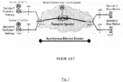
- a Transport Operator has to provide its mobile customers with IEEE1588 based transport services, illustrated in Figure 1 , configured to provide the best final quality.
- OTN optical transport network
- ITU-T Recommendation G.709 the following three options are being investigated for implementation as standards: PTP as a client (over Ethernet) [Transparent Transport]; PTP in the OTN Overhead and BC in the OTN network elements; and PTP in the optical supervisory channel, OSC, and BC in the OTN network elements and Line Amplifiers.
- the first option may look like the simplest one; the OTN network is unaware of the IEEE1588 messages that are transported across it, and the OTN network maps and transports communications traffic flows (e.g. 10Gb Ethernet) without knowing their contents. Therefore the IEEE1588 messages contained within OTN packets pass through the OTN network in a transparent way.
- the first option adheres to the OTN basic concept of enabling transparent transport of client communications traffic and it is suitable for multi-operator networks (as there is no need to extract and process PTP messages).
- Ethernet Client Mapping and Demapping forward error correction, FEC; Different Fiber Lengths; Different Wavelengths; Protection Switching; ODU multiplexing and so on.
- the second option offers the benefit that asymmetries and noise due to OTN mapping/demapping and FEC are avoided.
- it suffers the disadvantage that it goes against the basic principle of transporting client traffic over an OTN network.
- the second option would be feasible only in the case of a single network operator, where the OTN network element at the end handles the network time. In order to handle the timing of multiple clients with this approach, this option would require an unrealistic implementation of the OTN network element in which multiple BC instances are implemented, each of them handling the time of a different client.
- This option also suffers the disadvantages of requiring synchronization of all network elements in the OTN network (i.e. handling of an additional synchronization network), asymmetries due to fibre length and dispersion compensating fibre, DCF, are still to be addressed, and specific hardware would be required in the OTN network elements.
- the third option also suffers the problems of requiring synchronization of all network elements in the OTN network (i.e. handling of an additional synchronization network), specific hardware would be required in the OTN network elements and Line Amplifiers, and asymmetries due to fibre length are still to be addressed.
- the current options are therefore each characterized by some limitations.
- One main limitation with the second and third options is the need to handle a specific synchronization network where all OTN nodes need to be synchronized.
- Another limitation with the second and third options is the ability to only support a single network operator.
- the first option is the only one suitable for use in multi-operator networks but its implementation would require significant modifications to be implemented in the OTN network requirements and in the OTN network hardware to achieve an acceptable level of quality.
- Sebastien Jobert et al provides an "Analysis of phase/time distribution over OTN networks" in France Telecom's contribution to ITU-T SG15, Q13, Geneva, February 2011.
- a first aspect of the invention provides a method of distributing clock synchronization information within an optical communications network comprising a plurality of network elements.
- the method comprises step a. of receiving an ingress clock synchronization message at a first said network element.
- the ingress clock synchronization message comprises a clock synchronisation message identifier and a correction field.
- the method comprises step b. of inserting the clock synchronisation message identifier into an optical channel frame overhead and inserting the ingress clock synchronisation message into an optical channel frame payload.
- the method comprises step c. of transmitting the optical channel frame overhead and the optical channel frame payload across the first network element, across the network to a second said network element, and across the second network element. Step c.
- the method further comprises determining a transit time of the clock synchronisation message identifier across each of the network elements.
- the method comprises step d., carried out at the second network element, of updating the correction field of the ingress clock synchronisation message with said transit times to form an egress clock synchronisation message.
- the method may enable clock synchronisation information to be distributed between network elements an optical communications network without requiring the network elements to be synchronised and may therefore be used with a fully asynchronous network. Each network element may therefore maintain its own synchronisation source according to its own criteria and to the network planning and strategy.
- the method may enable respective clock synchronisation information to be distributed between network elements for each of a plurality of transport operators, each of which may have their own network time.
- step b. further comprises inserting an indication of an arrival time of the clock synchronisation message into the optical channel frame overhead.
- Step c. comprises step i. of determining a transit time of the clock synchronisation message identifier across the first network element, and inserting the transit time into the optical channel frame overhead.
- Step c. comprises step ii. of compiling an optical channel frame comprising the optical channel frame overhead and the optical channel frame payload.
- Step c. comprises step iii. of transmitting the optical channel frame from the first network element to the second network element.
- step c. comprises step iv., carried out at the second network element, of receiving the optical channel frame and obtaining the transit time from the optical channel frame overhead.
- Step c. comprises step v.
- Step d. comprises extracting the ingress clock synchronisation message from the optical channel frame payload and updating the correction field with a sum of the respective transit times across each said network element to form the egress clock synchronisation message.
- Inserting only the clock synchronisation message identifier and an indication of an arrival time of the clock synchronisation message into the overhead may reduce the bandwidth of the information to be placed in the overhead.
- step c. iii. comprises transmitting the optical channel frame from the first network element to an intermediate network element.
- Step c. iii. further comprises, at the intermediate network element, determining a transit time of the clock synchronisation message identifier across the intermediate network element and adding said transit time to the transit time in the optical channel frame overhead.
- Step c. iii. further comprises transmitting the optical channel frame from the intermediate network element to the second network element.
- the method may enable clock synchronisation information to be distributed across an optical communications network without requiring the network elements of the network to be synchronised and may therefore be used with a fully asynchronous network.
- the method may enable respective clock synchronisation information to be distributed across the same optical communications network for each of a plurality of transport operators, each of which may have their own network time.
- the method may distribute clock synchronisation information across an optical communications network without requiring the correction field to be updated at each intermediate network element, the correction field of the clock synchronisation message only being updated at the final network element, to form an egress clock synchronisation message.
- step c. iii. the optical channel frame is transmitted from the first network element to the second network element via a plurality of intermediate network elements, and a respective transit time is determined at each intermediate network element and added to the transit time in the optical channel frame overhead.
- the clock synchronisation message is a precision timing protocol event message.
- the method may be used to distribute PTP frequency and/or Time of Day ToD across a network.
- the transit time across each said network element is determined using an end-to-end transparent clock function.
- the end-to-end transparent clock is based on the principle of the end to end transparent clock function defined in the IEEE 1588 Standard.
- Implementing the method with end-to-end transparent clocks may significantly simplify the distribution of clock synchronisation information across a network.
- Using an optical channel frame overhead to transport clock synchronisation information together with implementing transparent clocks to determine the transit time across each network element, network element by network element may enable the method to overcome the single transport operator limitation faced by the prior art, enabling respective clock synchronisation information to be distributed between network elements for each of a plurality of transport operators. This may enable the best final quality of service to be provided in a relatively simple and cost effective manner.
- the method further comprises determining a link delay between each adjacent pair of network elements between which the optical channel frame is transmitted.
- the transit time across each said network element is determined using a methodology analogous to the peer-to-peer transparent clock function defined in the IEEE 1588 Standard.
- the method comprises, at each network element, providing an indication of an arrival time of the clock synchronisation message identifier and an indication of an exit time of the clock synchronisation message identifier, and the transit time is determined as the difference between the arrival time and the exit time. This may minimise the number of calculations required to determine the transit time.
- the optical channel frame overhead comprises a frame alignment word.
- each transit time is determined by comparing a position of the frame alignment word with a respective reference frame alignment word position. This may minimise the number of calculations required to determine the transit time.
- step a. further comprises calculating a frame period of the clock synchronisation message.
- the optical communications network is an optical transport network and the optical channel frame is an optical transport network frame.
- the optical channel frame overhead is an optical transport unit overhead.
- the optical channel frame overhead is an optical channel data unit overhead and the optical channel frame payload is an optical channel data unit.
- the optical channel frame overhead is an optical supervisory channel frame overhead.
- Use of the optical supervisory channel frame overhead may enable asymmetries due to transmission across dispersion compensating fibre and fibre length asymmetries to be corrected for.
- step b the clock synchronisation message identifier is inserted into an optical channel frame overhead by copying the clock synchronisation message identifier into the optical channel frame overhead. Copying the clock synchronisation message identifier without removing the message from the payload may avoid bandwidth variations within the optical channel frame payload. Moreover by only copying the message identifier into the overhead rather than the full message waste of the bandwidth of the optical channel frame overhead may be avoided.
- step b the clock synchronisation message identifier is inserted into an optical channel frame overhead by extracting the clock synchronisation message identifier from the clock synchronisation message and inserting the extracted clock synchronisation message identifier into the optical channel frame overhead.
- each ingress clock synchronisation message is inserted into an optical channel frame overhead.
- step a a plurality of ingress clock synchronisation messages are received at the first network element.
- step b. a respective clock synchronisation message identifier of each ingress clock synchronisation message is inserted into the optical channel frame overhead and each ingress clock synchronisation message is inserted into the optical channel frame payload.
- step c. the respective transit times across the network elements are the transit times of all the clock synchronisation message identifiers.
- step d. the respective correction field of each ingress clock synchronisation message is updated with a sum of the respective transit times across each said network element to form a plurality of egress clock synchronisation messages.
- step d a respective arrival time of each ingress clock synchronisation message is inserted into the optical channel frame overhead.
- each ingress clock synchronisation message is extracted from the optical channel frame payload and then each respective correction field is updated with a sum of the respective transit times across each said network element to form a plurality of egress clock synchronisation messages.
- Inserting only the clock synchronisation message identifier and an indication of an arrival time of the clock synchronisation message into the overhead may minimise the bandwidth of the information to be placed in the overhead for each clock synchronisation message, and may maximise the number of clock synchronisation messages which may be transported in a single optical channel frame.
- a second aspect of the invention provides a data carrier having computer readable instructions embodied therein for providing access to resources available on a processor.
- the computer readable instructions comprising instructions to cause the processor to perform any of the above steps of the method of distributing clock synchronization information within an optical communications network.
- the data carrier is a non-transitory data carrier.
- a third aspect of the invention provides a first optical communications network element configured to receive an ingress clock synchronization message.
- the ingress clock synchronization message comprises a clock synchronisation message identifier and a correction field.
- the first optical communications network element is configured to insert the clock synchronisation message identifier into an optical channel frame overhead.
- the first optical communications network element is configured to insert the ingress clock synchronisation message into an optical channel frame payload.
- the first optical communications network element is configured to transmit the optical channel frame overhead and payload across the first network element.
- the first optical communications network element is configured to determine a transit time of the clock synchronisation message identifier across the first optical communications network element.
- the first optical communications network element is configured to generate and transmit an optical signal carrying the optical channel frame overhead and the optical channel frame payload.
- the first network element may enable clock synchronisation information to be distributed to another network element an optical communications network without requiring the network elements to be synchronised.
- the first network element may therefore be used to construct of a fully asynchronous network.
- Each network element may maintain its own synchronisation source according to its own criteria and to the network planning and strategy.
- the first network element may enable respective clock synchronisation information to be distributed to another network element for each of a plurality of transport operators, each of which may have their own network time. Inserting only the clock synchronisation message identifier into the overhead may reduce the bandwidth of the information to be placed in the overhead.
- the first network element is configured to insert an indication of an arrival time of the clock synchronisation message into the optical channel frame overhead.
- the first optical communications network element is configured to insert the transit time into the optical channel frame overhead.
- the first optical communications network element is configured to compile an optical channel frame comprising the optical channel frame overhead and the optical channel frame payload.
- the first optical communications network element is configured to generate and transmit an optical signal carrying the optical channel frame.
- Inserting only the clock synchronisation message identifier and an indication of an arrival time of the clock synchronisation message into the overhead may reduce the bandwidth of the information to be placed in the overhead.
- the clock synchronisation message is a precision timing protocol event message.
- the first network element may be used to distribute PTP frequency and/or Time of Day ToD to another network element within a network.
- the first optical communications network element comprises one of an end-to-end transparent clock function based on the transparent clock function defined in the IEEE 1588 Standard and a peer-to-peer transparent clock function based on the transparent clock function defined in the IEEE 1588 Standard.
- Using an end-to-end transparent clock together with transporting clock synchronisation information in an optical channel frame overhead may significantly simplify the distribution of clock synchronisation information between network elements.
- Using an optical channel frame overhead to transport clock synchronisation information together with implementing transparent clocks to determine the transit time across the first network element may enable the first network element to distribute respective clock synchronisation information for each of a plurality of transport operators.
- the first network element is configured to provide an indication of an exit time of the clock synchronisation message identifier.
- the first network element is configured to determine the transit time as the difference between the arrival time and the exit time. This may minimise the number of calculations required to determine the transit time.
- the optical channel frame overhead comprises a frame alignment word.
- the first network element is configured to determine the transit time by comparing a position of the frame alignment word with a reference frame alignment word position. This may minimise the number of calculations required to determine the transit time.
- the optical communications network is an optical transport network and the optical channel frame is an optical transport network frame.
- the optical channel frame overhead is an optical transport unit overhead.
- the optical channel frame overhead is an optical channel data unit overhead and the optical channel frame payload is an optical channel data unit.
- the optical channel frame overhead is an optical supervisory channel frame overhead.
- Use of the optical supervisory channel frame overhead may enable asymmetries due to transmission across dispersion compensating fibre and fibre length asymmetries to be corrected for.
- the first network element is configured to insert the clock synchronisation message identifier into an optical channel frame overhead by copying the clock synchronisation message identifier into the optical channel frame overhead. Copying the clock synchronisation message identifier without removing the message from the payload may avoid bandwidth variations within the optical channel frame payload. Moreover by only copying the message identifier into the overhead rather than the full message waste of the bandwidth of the optical channel frame overhead may be avoided.
- the first network element is configured to insert the clock synchronisation message identifier into an optical channel frame overhead by extracting the clock synchronisation message identifier from the clock synchronisation message and placing the extracted clock synchronisation message identifier into the optical channel frame overhead.
- the first network element is further configured to calculate a frame period of the clock synchronisation message.
- the first network element is configured to insert the clock synchronisation message, including the clock synchronisation message identifier, into an optical channel frame overhead.
- the first network element is configured to receive a plurality of ingress clock synchronisation messages.
- the first network element is configured to insert each clock synchronisation message identifier into the optical channel frame overhead and to insert each ingress clock synchronisation message into the optical channel frame payload
- the first network element is configured to extract a clock synchronisation message identifier from each ingress clock synchronisation message and then to insert each clock synchronisation message identifier and a respective arrival time of each ingress clock synchronisation message into the optical channel frame overhead.
- Inserting only the clock synchronisation message identifier and an indication of an arrival time of each ingress clock synchronisation message into the overhead may minimise the bandwidth of the information to be placed in the overhead for each ingress clock synchronisation message, and may maximise the number of ingress clock synchronisation messages which may be transported in a single optical channel frame.
- the first network element is configured to insert each ingress clock synchronisation message, including the clock synchronisation message identifier, into an optical channel frame overhead.
- a fourth aspect of the invention provides a second optical communications network element configured to receive an optical channel frame overhead and an optical channel frame payload from an optical communications network.
- the optical channel frame overhead comprises a clock synchronisation message identifier.
- the optical channel frame payload comprises an ingress clock synchronisation message, which comprises the clock synchronisation message identifier and a correction field.
- the second network element is configured to transmit the optical channel frame across the second network element.
- the second network element is configured to determine a transit time of the clock synchronisation message identifier across the second network element.
- the second network element is configured to obtain a transit time of the clock synchronisation message identifier across at least one other network element in said optical communications network.
- the second network element is configured to update the correction field of the ingress clock synchronisation message with a sum of the said transit times to form an egress clock synchronisation message.
- the second network element may enable clock synchronisation information to be received from another network element an optical communications network without requiring the network elements to be synchronised.
- the second network element may therefore be used to construct of a fully asynchronous network.
- Each network element may maintain its own synchronisation source according to its own criteria and to the network planning and strategy.
- the second network element may enable respective clock synchronisation information to be received from another network element for each of a plurality of transport operators, each of which may have their own network time.
- the optical channel frame overhead further comprises the transit time of the clock synchronisation message identifier across said at least one other network element.
- the second optical communications network element is configured to, in step ii., obtain the transit time of the clock synchronisation message identifier across the at least one other network element from the optical channel frame overhead.
- the second network element is configured to, in step iii., extract the ingress clock synchronisation message from the optical channel frame payload and to then update the correction field with a sum of the said transit times to form the egress clock synchronisation message.
- the clock synchronisation message is a precision timing protocol event message.
- the second network element may be used to receive PTP frequency and/or Time of Day ToD from another network element within a network.
- the second optical communications network element comprises one of an end-to-end transparent clock function based on the transparent clock function defined in the IEEE 1588 Standard and a peer-to-peer transparent clock function on the transparent clock function defined in the IEEE 1588 Standard.
- Using an end-to-end transparent clock function together with transporting clock synchronisation information in an optical channel frame overhead may significantly simplify the distribution of clock synchronisation information between network elements.
- Using an optical channel frame overhead to transport clock synchronisation information together with implementing transparent clocks to determine the transit time across the second network element may enable the second network element to receive respective clock synchronisation information for each of a plurality of transport operators.
- the second optical communications network element is configured to determine a link delay between itself and a network element from which the optical channel frame is received.
- the transit time across each the second optical communications network element is determined using a methodology analogous to the peer-to-peer transparent clock function defined in the IEEE 1588 Standard.
- the second network element is configured to provide an indication of an arrival time of the clock synchronisation message identifier and an indication of an exit time of the clock synchronisation message identifier.
- the second network element is configured to determine the transit time as the difference between the arrival time and the exit time. This may minimise the number of calculations required to determine the transit time.
- the optical channel frame overhead comprises a frame alignment word.
- the second network element is configured to determine the transit time by comparing a position of the frame alignment word with a reference frame alignment word position. This may minimise the number of calculations required to determine the transit time.
- the second network element is further configured to calculate a frame period of the clock synchronisation message.
- the optical communications network is an optical transport network and the optical channel frame is an optical transport network frame.
- the optical channel frame overhead is one of an optical transport unit frame overhead and an optical supervisory channel frame overhead. Use of the optical supervisory channel frame overhead may enable asymmetries due to transmission across dispersion compensating fibre and fibre length asymmetries to be corrected for.
- the second network element is configured to extract a plurality of clock synchronisation messages from the optical channel frame overhead.
- the second network element is configured to update the respective correction field of each ingress clock synchronisation message with a sum of the respective transit times across each said network element to form a plurality of egress clock synchronisation messages.
- a fifth aspect of the invention provides an optical communications network comprising a first optical communications network element and a second optical communications network element.
- the first optical communications network element configured to receive an ingress clock synchronization message.
- the ingress clock synchronization message comprises a clock synchronisation message identifier and a correction field.
- the first optical communications network element is configured to insert the clock synchronisation message identifier into an optical channel frame overhead.
- the first optical communications network element is configured to insert the ingress clock synchronisation message into an optical channel frame payload.
- the first optical communications network element is configured to transmit the optical channel frame overhead and payload across the first network element.
- the first optical communications network element is configured to determine a transit time of the clock synchronisation message identifier across the first optical communications network element.
- the first optical communications network element is configured to generate and transmit an optical signal carrying the optical channel frame overhead and the optical channel frame payload.
- the second optical communications network element configured to receive the optical channel frame overhead and the optical channel frame payload.
- the second network element is configured to transmit the optical channel frame overhead and the optical channel frame payload across the second network element.
- the second network element is configured to determine a transit time of the clock synchronisation message identifier across the second network element.
- the second network element is configured to obtain a transit time of the clock synchronisation message identifier across the first network element.
- the second network element is configured to update the correction field of the ingress clock synchronisation message with a sum of the said transit times to form an egress clock synchronisation message.
- the optical communications network may enable clock synchronisation information to be distributed the network without requiring the network elements to be synchronised.
- the network element may therefore be a fully asynchronous network.
- Each network element may maintain its own synchronisation source according to its own criteria and to the network planning and strategy.
- the network may enable respective clock synchronisation information to be distributed across the network for each of a plurality of transport operators, each of which may have their own network time. Inserting only the clock synchronisation message identifier into the overhead may reduce the bandwidth of the information to be placed in the overhead.
- the first network element is configured to insert an indication of an arrival time of the clock synchronisation message into the optical channel frame overhead.
- the first optical communications network element is configured to insert the transit time into the optical channel frame overhead.
- the first optical communications network element is configured to compile an optical channel frame comprising the optical channel frame overhead and the optical channel frame payload.
- the first optical communications network element is configured to generate and transmit an optical signal carrying the optical channel frame.
- Inserting only the clock synchronisation message identifier and an indication of an arrival time of the clock synchronisation message into the overhead may reduce the bandwidth of the information to be placed in the overhead.
- the clock synchronisation message is a precision timing protocol event message.
- the network may be used to distribute PTP frequency and/or Time of Day ToD across the network.
- each optical communications network element comprises one of an end-to-end transparent clock function and a peer-to-peer transparent clock function.
- the end-to-end transparent clock function is based on the principle of the end to end transparent clock function defined in the IEEE 1588 Standard.
- the peer-to-peer transparent clock function is based on the principle of the peer-to-peer transparent clock function defined in the IEEE 1588 Standard.
- Using an end-to-end transparent clock function together with transporting clock synchronisation information in an optical channel frame overhead may significantly simplify the distribution of clock synchronisation information between network elements.
- Using an optical channel frame overhead to transport clock synchronisation information together with implementing transparent clocks to determine the transit time across the network elements, may enable the network to distribute respective clock synchronisation information for each of a plurality of transport operators.
- each network element is configured to provide an indication of an exit time of the clock synchronisation message identifier.
- Each network element is configured to determine the transit time as the difference between the arrival time and the exit time. This may minimise the number of calculations required to determine each transit time.
- the optical channel frame overhead comprises a frame alignment word.
- Each network element is configured to determine the respective transit time by comparing a position of the frame alignment word with a respective reference frame alignment word position. This may minimise the number of calculations required to determine each transit time.
- the optical communications network is an optical transport network and the optical channel frame is an optical transport network frame.
- the optical channel frame overhead is an optical transport unit overhead.
- the optical channel frame overhead is an optical channel data unit overhead and the optical channel frame payload is an optical channel data unit.
- the optical channel frame overhead is an optical supervisory channel frame overhead.
- Use of the optical supervisory channel frame overhead may enable asymmetries due to transmission across dispersion compensating fibre and fibre length asymmetries to be corrected for.
- the first network element is configured to insert the clock synchronisation message identifier into an optical channel frame overhead by copying the clock synchronisation message identifier into the optical channel frame overhead. Copying the clock synchronisation message identifier without removing the message from the payload may avoid bandwidth variations within the optical channel frame payload. Moreover by only copying the message identifier into the overhead rather than the full message waste of the bandwidth of the optical channel frame overhead may be avoided.
- the first network element is configured to insert the clock synchronisation message identifier into an optical channel frame overhead by moving the clock synchronisation message identifier from the clock synchronisation message into the optical channel frame overhead.
- the first network element is further configured to calculate a frame period of the clock synchronisation message.
- the first network element is configured to insert the clock synchronisation message, including the clock synchronisation message identifier, into an optical channel frame overhead.
- the first network element is configured to receive a plurality of ingress clock synchronisation messages.
- the first network element is configured to insert each clock synchronisation message identifier into the optical channel frame overhead and to insert each ingress clock synchronisation message into the optical channel frame payload
- the first network element is configured to extract a clock synchronisation message identifier from each ingress clock synchronisation message and then to insert each clock synchronisation message identifier and a respective arrival time of each ingress clock synchronisation message into the optical channel frame overhead.
- Inserting only the clock synchronisation message identifier and an indication of an arrival time of each ingress clock synchronisation message into the overhead may minimise the bandwidth of the information to be placed in the overhead for each ingress clock synchronisation message, and may maximise the number of ingress clock synchronisation messages which may be transported in a single optical channel frame.
- the first network element is configured to insert each ingress clock synchronisation message, including the clock synchronisation message identifier, into an optical channel frame overhead.
- the second optical communications network element is configured to, in step ii., obtain the transit time of the clock synchronisation message identifier across the at least one other network element from the optical channel frame overhead.
- the second network element is configured to, in step iii., extract the ingress clock synchronisation message from the optical channel frame payload and to then update the correction field with a sum of the said transit times to form the egress clock synchronisation message.
- the second optical communications network element is configured to determine a link delay between itself and a network element from which the optical channel frame is received.
- the second network element is configured to extract a plurality of clock synchronisation messages from the optical channel frame overhead.
- the second network element is configured to update the respective correction field of each ingress clock synchronisation message with a sum of the respective transit times across each said network element to form a plurality of egress clock synchronisation messages.
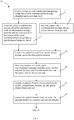
- Figure 2 shows the steps of a method 1 of distributing clock synchronization information within an optical communications network comprising a plurality of network elements, according to a first embodiment of the invention.
- the method 1 comprises:
- step b. further comprises inserting an indication of an arrival time of the clock synchronisation message into the optical channel frame overhead 14.
- Step c. comprises:
- Step d. comprises extracting the ingress clock synchronisation message from the optical channel frame payload and updating the correction field with a sum of the respective transit times across each said network element to form the egress clock synchronisation message 32.
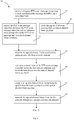
- a third embodiment of the invention provides a method of distributing clock synchronization information within an optical communications network comprising a plurality of network elements.
- the method of this embodiment is similar to the method 10 of the first embodiment, with the following modifications.
- step c. iii. 40 comprises a first step of transmitting the optical channel frame from the first network element to an intermediate network element 42.
- Step c. iii. further comprises, at the intermediate network element, determining a transit time of the clock synchronisation message identifier across the intermediate network element 44. The transit time which has been determined is then added to the transit time in the optical channel frame overhead 44.
- Step. c. iii. further comprises transmitting the optical channel frame from the intermediate network element to the second network element 46.
- step c. iii. may comprise transmitting the optical channel frame from the first network element to the second network element via a plurality of intermediate network elements, the transit time across each intermediate network element being determined and added to the transit time in the optical channel frame overhead received at each respective intermediate network element.
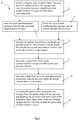
- Figures 6 and 7 show the steps of a method 50 of distributing clock synchronization information within an optical communications network comprising a plurality of network elements according to a fourth embodiment of the invention.
- the method 50 of this embodiment is similar to the method 10 shown in Figures 3 and 4 , with the following modifications.
- the same reference numbers are retained for corresponding steps.
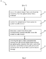
- the clock synchronization message is a precision timing protocol, PTP, event message.
- the PTP event message is received 52 at the first network element and the PTP event message identifier is extracted and inserted, with an indication of its arrival time, into an optical channel frame overhead 54.
- the PTP event message itself is inserted into an optical channel frame payload 56.
- the transit time of the PTP event message identifier across the first network element is determined and the transit time inserted into the optical channel frame overhead 58.
- the transit time of the PTP event message identifier across the second network element is determined 60.
- the PTP event message is extracted from the optical channel frame payload and the PTP event message correction field is updated with a sum of the respective transit times across each said network element, to form an egress PTP event message 62.
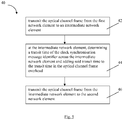
- a fifth embodiment of the invention provides a method 70 of distributing clock synchronization information within an optical communications network comprising a plurality of network elements.
- the method of this embodiment is similar to the method 1 of the first embodiment, with the following modifications.
- step d. additionally comprises determining a link delay between each adjacent pair of network elements between which the optical channel frame is transmitted 72.
- the correction field of the ingress clock synchronisation message is additionally updated with the link delay to form the egress clock synchronisation message 74.
- the method of this embodiment uses a methodology analogous to the peer-to-peer transparent clock function defined in the IEEE 1588 Standard. It will therefore be appreciated by the person skilled in the art that the method 70 will involve the exchange of specific messages between adjacent nodes in order to determine the link delay.
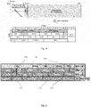
- a sixth embodiment of the invention provides a method of distributing clock synchronization information within an optical communications network comprising a plurality of network elements 80, 90, 100.
- a Gbit/s client signal carrying an ingress IEEE 1588 PTP event message 82 is received at the first network element, which in this example is a mapper 80.
- the ingress PTP event message 82 comprises a PTP event message identifier and a correction field.
- the mapper comprises an edge-to-edge transparent clock function, TC (not illustrated).
- the ingress PTP event message 82 On receipt at the mapper the ingress PTP event message 82 is time stamped with its arrival time by the TC. The PTP event message identifier is extracted from the PTP event message. The PTP event message identifier and the arrival time, which together will be referred to here as PTP information 84, are inserted into an OTN overhead 88, as shown in Figures 10 and 11 . The PTP event message 82 is inserted into an OTN payload 96, as shown in Figure 10 .
- the OTN overhead and payload are transmitted across the mapper 80 and time stamped with the exit time of the OTN overhead by the TC.
- the TC then calculates the transit time of the OTN overhead across the mapper as the difference between the arrival time and the exit time.
- the transit time is inserted into a PTP information correction field in the OTN overhead, to form an updated PTP information 86.
- the mapper 80 compiles an OTN frame from the OTN overhead 88 and the OTN payload 96 and transmits a carrier signal carrying the OTN frame to an intermediate network element 90.
- the intermediate network element is a multiplexer/switch, mux/switch, 90 and also comprises a TC (not illustrated).
- the OTN frame On receipt at the mux/switch the OTN frame is time stamped with the arrival time of the OTN overhead 88. The arrival time at the mux/switch is inserted into the OTN overhead, to form an updated PTP information 92.
- the OTN frame is transmitted across the mux/switch and is time stamped with the exit time of the OTN overhead.
- the TC then calculates the transit time of the OTN overhead across the mux/switch as the difference between the arrival time and the exit time. The transit time is added to the transit time across the mapper in the PTP information correction field, to form an updated PTP information 94.
- the mux/switch generates a further carrier signal carrying the OTN frame to the second network element 100.
- the second network element is a demapper 100 and comprises a TC (not illustrated).
- the OTN frame On receipt at the demapper the OTN frame is time stamped with the arrival time of the OTN overhead 88. The arrival time at the demapper is inserted into the OTN overhead, to form an updated PTP information 102.
- the OTN frame is transmitted across the demapper and the PTP event message is extracted from the OTN payload 96.
- the PTP event message is time stamped with its exit time from the demapper.
- the TC then calculates the transit time of the PTP event message identifier across the demapper. The transit time is added to the sum of the transit times across the mapper and the mux/switch in the PTP information correction field, to form an updated PTP information 104.
- the demapper extracts the ingress PTP event message from the OTN payload and updates the correction field of the ingress PTP event message with the accumulated transit times, to form an egress PTP event message 106.
- the PTP information 84 will be placed in a suitable number of overhead bytes which are not used for other purposes and which are therefore free.
- the RES Reserved Bytes
- the general communications channel 1, GCC1, or GCC2 or other bytes may be used if free and available.
- the RES bytes (ROW 2, COLUMNS 1 and 2 AND ROW 4, COLUMNS 9 to 14) provide up to 8 bytes per frame.
- An OTU2 frame is 12.191 ⁇ s in length giving 82027 frames per second. Considering 8 bytes (64 bits) this gives 5.25Mbit/s of raw bandwidth.
- a typical IEEE 1588 implementation uses PTP event messages having a packet length of 128 bytes and a transmission rate of 20 packets/second. This would give a raw bandwidth of 20 kbit/sec.
- the IEEE 1588 transmission rate is less than 128 packets/second, giving a worst case raw bandwidth of 131kbit/second per PTP event message flow.
- the PTP event message 82 is modified before it is inserted, in this example copied, into the OTN overhead 88.
- the essential information namely an identifier of the message plus the related timestamp, is inserted into the OTN overhead.
- 'PTP information' is used herein to mean either of a full PTP event message or this reduced PTP event message.
- the packet length of the ingress PTP event message (128 bytes) may therefore be reduced a lot before being inserted into the OTN overhead and consequently the best case raw bandwidth will be less than 10 kbit/sec.
- the OTU2 RES having an available bandwidth of 5.25Mbit/s it is possible to insert a PTP event message from each of 40 PTP event message flows, each PTP event message flow having a bandwidth of 131kbit in the worst case.
- a PTP event message from each of 262 flows each having a bandwidth of 20kbit, can be inserted in the OTU2 RES, and a PTP event message from each of more than 500 flows, each having a bandwidth of less than 10kbit can be inserted in the OTU2 RES in the best case.
- OTU2 frame is able to contain up to 8 different optical channel data unit containers (ODU0), therefore inserting between 40 and 500, with 262 as a typical number, IEEE 1588 PTP event message flows is absolutely well acceptable.
- ODU0 optical channel data unit containers
- OTU3 and OTU4 frames may alternatively be used.
- Increasing the OTUn level means that the number of ODU0 containers increases but the frame period decreases in the same ratio (increasing the resulting available bandwith in the same ratio as well).
- an OTU3 is able to contain up to 32 ODU0 containers but its period is around 4 times shorter in comparison to OTU2 (3.035 ⁇ s) and the available bandwith is 21.087Mbit/s.
- a network operator will be able to configure the number of RES bytes dedicated to this functionality, between 0 and 8, and therefore the maximum number of PTP event message flows which may be transported in a single OTU frame.
- the method of this embodiment comprises extracting the PTP information carried by the client signal (e.g. an IEEE 1588 PTP event message carried over Gbit/s client) at the first network element (the 'mapper') and inserting it into the OTN overhead. From this point onwards each network element calculates the transit time across itself and updates PTP information correction field.
- the OTN overhead may be the optical transport unit, OTU, overhead or the OSC overhead.
- the accumulated transit time in the PTP information correction field is used to modify the correction field of the outgoing PTP event message.
- the method described in this embodiment uses an transparent clock function based on the "End-to-end” Transparent clock, as defined in the IEEE 1588 Standard, but it will be appreciated by the person skilled in the art that a "Peer-to-peer" Transparent Clock function based on that defined in the IEEE 1588 Standard may alternatively be used.
- the benefit in implementing method described in this embodiment with the transparent clock function is to significantly simplify the distribution of clock synchronisation information.
- the OSC overhead may alternatively be used. If this is not acceptable due to standardization issues, asymmetries due to fiber length and DCF may be addressed by alternative methods.
- the combination of use of the OTN overhead for PTP event message transport and the implementation of TC in each network element may overcome the single-operator limitation and may enable network operators to achieve the best final quality with a relative simple and cost-effective approach.
- the method of this embodiment may also minimize OTN overhead redefinitions and changes.
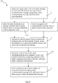
- a seventh embodiment of the invention provides a method of distributing clock synchronization information within an optical communications network which is similar to the method of the previous embodiment, with the following modifications.
- the method is for use with OTN network elements 120 which comprise an ODU0 switching fabric 126 and the OTN overhead is an ODU0 overhead.
- the ingress PTP event message 122 is received at an ingress interface 124 and time stamped.
- the PTP event message identifier is inserted into an ODU0 overhead, as shown in Figure 13 , together with the arrival time, and the PTP event message is inserted into an ODU0 payload container.
- the PTP event message identifier is inserted into an ODU0 overhead at first network element ('mapper' 80) by either moving the PTP event message identifier from the ingress PTP event message and inserting it into the ODU0 overhead or by copying the PTP even message identifier and inserting the copy into the ODU0 overhead.
- Copying optimizes the required hardware in the second network element ('demapper' 100). Copying also provides the advantage that the need to overwrite some fields and not to add them to the egress PTP event message will mean that there are no bandwidth variations and therefore no need for schedulers/traffic managers at the second network element, which would result in additional costs and impairing and unavoidable delay variations.
- the ODU0 is forwarded towards the ODU0 switching fabric 126.
- the PTP information 86 in the OTN overhead received from the mapper is copied into a new ODU0 overhead before forwarding the new ODU0 overhead to the ODU0 switching fabric.
- the PTP information is copied into a new ODU0 overhead because the ODU0 overhead received from the mapper is terminated at the mux/switch.
- the method comprises configuring each ODU0 switching fabric 126 to cross-connect the ODU0 payload container with its ODU0 overhead, to thereby cross-connect the PTP event message towards a desired egress port 128 of the respective network element.
- the ODU0 overhead and payload are compiled into an ODU frame and a client signal 130 carrying the ODU frame is generated and transmitted.
- Figure 14 shows the steps of a method 130 of distributing clock synchronization information within an optical communications network according to an eighth embodiment of the invention.
- the method 130 of this embodiment is similar to the method 1 of Figure 2 , with the following modifications.
- the same reference numbers are retained for corresponding features.
- the clock synchronisation message identifier is inserted into an optical channel frame overhead comprising a frame alignment word.
- each transit time is determined by comparing a position of the frame alignment word in the overhead with a respective reference frame alignment word position.
- a ninth embodiment of the invention provides a method of distributing clock synchronization information within an optical communications network which is similar to the method 130 of the previous embodiment, with the following modifications.
- the arrival time of PTP information at each network element is periodic and the exit time of PTP information at each network element is also periodic. This allows some computational simplifications to be made to how the transit time is determined, as follows.
- Each optical channel frame received by a network element is characterized by its frame alignment word, FAW, and the same is true for each egress optical channel frame.
- FAW frame alignment word
- the position of the FAW 136 in an OTU frame 138 is shown in Figure 15 as the first block inserted into the OTU frame header 139.
- the arrival time can only be T1 or T1+T or T1+2T, etc.
- the method comprises configuring the OTN network element 120 to verify the position of the ODU0 payload container received from the ODU switching fabric 126 as compared to a reference egress FAW position to determine if the exit time will be T2+T or T2+2T or T2+3T etc, as shown in Figure 16 b) . Therefore the transit time across the network element is given by: T 2 ⁇ T 1 + nt and the computation of n is a very simple task.
- the method comprises storing a current FAW arrival time (T1, T1+T and so on) and updating the FAW arrival time when each new FAW is received.
- the method comprises storing a current FAW exit time (T2, T2+T and so on) and updating the FAW exit time when each new exit FAW is received.
- the FAW arrival time is inserted in the PTP event message itself using the PTP RES bytes (4 bytes) or by appending them to the PTP event message.
- the PTP RES bytes provide the FAW arrival time and therefore allow the FAW exit time to be calculated as: T 2 ⁇ T 1 + nT
- the PTP event message correction field is 8 bytes. In the correction field the correction is given in nanoseconds and multiplied by 216. This allows a range from 2-16ns to around 26 days. As will be appreciated by the person skilled in the art, neither of these values has any practical meaning as transit time across an OTN network element.
- the time range can be modified by applying a multiplication factor, for example a 28 or 24 multiplying factor, to the received correction.
- a multiplication factor for example a 28 or 24 multiplying factor
- the received channel frame period is not constant from port to port on the ingress interface 124 because it depends on the ingress (or egress) frequency of the PTP event message flow. This is because PTP event messages will be received from different network elements within a network and the network elements are asynchronous (the network elements have a nominal frequency and an acceptable variation about the nominal frequency which results in their being asynchronous).
- the method comprises calculating the frame period for each ingress port (this is the difference between the time stamps of two consecutive FAWs) and the frame period for each egress port.
- Each ingress port and egress port has a clock, and the ingress and egress clocks are affected by jitter (high frequency sinusoidal jitter has a zero mean value and therefore does not significantly affect the calculation) and slow wander or frequency drift (that can result in a bigger impairment).
- jitter high frequency sinusoidal jitter has a zero mean value and therefore does not significantly affect the calculation
- slow wander or frequency drift that can result in a bigger impairment.
- the different frame periods (T3, T4) are up-dated from time to time.
- the update rate is calculated considering the expected frequency drift, the network design, and the final PTP quality targets, or can be dynamically adapted according to the results.
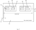
- a first optical communications network element 140 according to a tenth embodiment of the invention is shown in Figure 17 .
- the first optical communications network element 140 is configured to receive an ingress clock synchronization message 142 comprising a clock synchronisation message identifier and a correction field.
- the first optical communications network element 140 is configured to:
- a first optical communications network element 160 according to an eleventh embodiment of the invention is shown in Figure 18 .
- the first optical communications network element 160 of this embodiment is similar to the first optical communications network element 140 shown in Figure 17 , with the following modifications.
- the same reference numbers are retained for corresponding features.
- the clock synchronisation message is a PTP event message 164 and first optical communications network element 160 comprises an end-to-end transparent clock function, TC, 162.
- the first optical communications network element 160 is additionally configured to insert an indication of an arrival time of the PTP event message into the optical channel frame overhead 146, to provide PTP information 166 in the optical channel frame overhead.
- the first optical communications network element 160 is configured to insert the transit time into a PTP information correction field in the optical channel frame overhead, to update the PTP information 168.
- the first optical communications network element 160 is configured to compile an optical channel frame comprising the optical channel frame overhead 146 and the optical channel frame payload 150 and to generate and transmit an optical signal 169 carrying the optical channel frame.
- a twelfth embodiment of the invention provides a first optical communications network element which is similar to the second optical communications network element 140 shown in Figure 17 and which will be described with reference to that Figure.
- the optical channel frame overhead comprises a frame alignment word.
- the first network element 140 is configured to determine the transit time by comparing a position of the frame alignment word with a reference frame alignment word position.
- the first optical communications network element 140 is configured respectively to implement the steps of the methods described above in relation to Figures 5 to 16 which are carried out at the first optical communications network element.
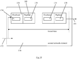
- a second optical communications network element 170 according to a thirteenth embodiment of the invention is shown in Figure 19 .
- the second optical communications network element 170 is configured to receive a carrier signal 172 carrying an optical channel frame overhead 176 and an optical channel frame payload 180 from an optical communications network.
- the optical channel frame overhead comprises a clock synchronisation message identifier 174 and the optical channel frame payload comprises an ingress clock synchronisation message 178.
- the clock synchronisation message comprises the clock synchronisation message identifier and a correction field.
- the second network element 170 is configured to:
- a fourteenth embodiment of the invention provides a second optical communications network element which is similar to the second optical communications network element 170 shown in Figure 19 and which will be described with reference to that Figure.
- the optical channel frame overhead further comprises the transit time of the clock synchronisation message identifier across said at least one other network element.
- the second optical communications network element 170 is configured to, in step ii., obtain the transit time of the clock synchronisation message identifier across the at least one other network element from the optical channel frame overhead.
- the second network element is configured to, in step iii., extract the ingress clock synchronisation message from the optical channel frame payload and to then update the correction field with a sum of the said transit times to form the egress clock synchronisation message 184.
- a second optical communications network element 190 according to a sixteenth embodiment of the invention is shown in Figure 20 .
- the second optical communications network element 190 of this embodiment is similar to the second optical communications network element 170 shown in Figure 19 , with the following modifications.
- the same reference numbers are retained for corresponding features.
- the clock synchronisation message is a PTP event message.
- the second optical communications network element comprises an end-to-end TC 192.
- a sixteenth embodiment of the invention provides a second optical communications network element which is similar to the second optical communications network element 170 shown in Figure 19 and which will be described with reference to that Figure.
- the optical channel frame overhead comprises a frame alignment word.
- the second network element 170 is configured to determine the transit time by comparing a position of the frame alignment word with a reference frame alignment word position.
- the second optical communications network element 170 is configured respectively to implement the steps of the methods described above in relation to Figures 5 to 16 which are carried out at the second optical communications network element.
- a seventeenth embodiment of the invention provides an optical communications network a first optical communications network element 140 and a second optical communications network element 170.
- first optical communications network element 160 and/or the second optical communications network element 160 may alternatively be used.
Claims (15)
- Procédé (1, 10, 40, 50, 70, 130) de distribution d'informations de synchronisation d'horloge à l'intérieur d'un réseau de communication optique comprenant une pluralité d'éléments de réseau, le procédé comprenant :a. la réception d'un message de synchronisation d'horloge d'entrée à un premier dit élément de réseau, le message de synchronisation d'horloge d'entrée comprenant un identifiant de message de synchronisation d'horloge et un champ de correction (2, 52) ;caractérisé parb. l'insertion de l'identifiant de message de synchronisation d'horloge dans un surdébit de trame de canal optique (3, 14, 54, 132) et l'insertion du message de synchronisation d'horloge d'entrée dans une charge utile de trame de canal optique (4 ; 56) ;c. la transmission du surdébit de trame de canal optique et de la charge utile de trame de canal optique à travers le premier élément de réseau, à travers le réseau jusqu'à un deuxième dit élément de réseau, et à travers le deuxième élément de réseau (5, 18, 22, 24, 42), et la détermination d'un temps de transport de l'identifiant de message de synchronisation d'horloge à travers chacun des éléments de réseau (6, 20, 44, 58, 60, 134) ; etd. au deuxième élément de réseau, la mise à jour du champ de correction du message de synchronisation d'horloge d'entrée avec lesdits temps de transport pour former un message de synchronisation d'horloge de sortie (7, 26, 28, 30, 32, 62, 74).
- Procédé selon la revendication 1, dans lequel :l'étape b. comprend en outre l'insertion d'une indication d'un temps d'arrivée du message de synchronisation d'horloge dans le surdébit de trame de canal optique (14, 54) ;l'étape c. comprend :i. la détermination d'un temps de transport de l'identifiant de message de synchronisation d'horloge à travers le premier élément de réseau, et l'insertion du temps de transport dans le surdébit de trame de canal optique (20, 134) ;ii. la compilation d'une trame de canal optique comprenant le surdébit de trame de canal optique et la charge utile de trame de canal optique (22) ;iii. la transmission de la trame de canal optique du premier élément de réseau au deuxième élément de réseau (24, 40) ;iv. au deuxième élément de réseau, la réception de la trame de canal optique et l'obtention du temps de transport à partir du surdébit de trame de canal optique (26) ; etv. la transmission de la trame de canal optique à travers le deuxième élément de réseau (28) et la détermination d'un temps de transport de l'identifiant de message de synchronisation d'horloge à travers le deuxième élément de réseau (30, 60) ; etl'étape d. comprend l'extraction du message de synchronisation d'horloge d'entrée à partir de la charge utile de trame de canal optique et la mise à jour du champ de correction avec une somme des temps de transport respectifs à travers chaque dit élément de réseau pour former le message de synchronisation d'horloge de sortie (32, 62, 74) .
- Procédé selon la revendication 2, dans lequel l'étape c. iii. (40) comprend :la transmission de la trame de canal optique du premier élément de réseau à un élément de réseau intermédiaire (42) ;à l'élément de réseau intermédiaire, la détermination d'un temps de transport de l'identifiant du message de synchronisation d'horloge à travers l'élément de réseau intermédiaire et l'ajout dudit temps de transport au temps de transport dans le surdébit de trame de canal optique (44) ; etla transmission de la trame de canal optique de l'élément de réseau intermédiaire au deuxième élément de réseau (46).
- Procédé selon l'une quelconque des revendications précédentes, dans lequel le message de synchronisation d'horloge est un message d'événement de protocole de timing de précision (52, 54, 56, 58, 60, 62).
- Procédé selon l'une quelconque des revendications précédentes, dans lequel le procédé comprend en outre la détermination d'un retard de liaison entre chaque paire adjacente d'éléments de réseau entre lesquels la trame de canal optique est transmise (72).
- Procédé selon l'une quelconque des revendications précédentes, dans lequel le surdébit de trame de canal optique comprend un mot d'alignement de trame et, à l'étape c., chaque temps de transport est déterminé par la comparaison d'une position du mot d'alignement de trame à une position de mot d'alignement de trame de référence respective (132, 134).
- Procédé selon l'une quelconque des revendications précédentes, dans lequel le réseau de communication optique est un réseau de transport optique et le surdébit de trame de canal optique est l'un d'un surdébit de trame d'unité de transport optique et d'un surdébit de trame de canal de supervision optique.
- Support de données sur lequel se trouvent des instructions lisibles par ordinateur pour fournir un accès à des ressources disponibles sur un processeur, les instructions lisibles par ordinateur comprenant des instructions pour amener le processeur à effectuer l'une quelconque des étapes du procédé de distribution d'informations de synchronisation d'horloge à l'intérieur d'un réseau de communication optique selon l'une quelconque des revendications précédentes.
- Premier élément de réseau de communication optique (140, 160) configuré pour recevoir un message de synchronisation d'horloge d'entrée (142, 164) comprenant un identifiant de message de synchronisation d'horloge et un champ de correction, caractérisé en ce que le premier élément de réseau de communication optique est configuré pour effectuer :l'insertion de l'identifiant de message de synchronisation d'horloge (144, 166) dans un surdébit de trame de canal optique (146) ;l'insertion du message de synchronisation d'horloge d'entrée dans une charge utile de trame de canal optique (150) ;la transmission du surdébit de trame de canal optique et de la charge utile de trame de canal optique à travers le premier élément de réseau,la détermination d'un temps de transport de l'identifiant de message de synchronisation d'horloge à travers le premier élément de réseau de communication optique ; etla génération et la transmission d'un signal optique (154, 169) portant le surdébit de trame de canal optique et la charge utile de trame de canal optique.
- Premier élément de réseau de communication optique selon la revendication 9, dans lequel le premier élément de réseau de communication optique est configuré pour effectuer :l'insertion d'une indication d'un temps d'arrivée du message de synchronisation d'horloge dans le surdébit de trame de canal optique (166) ;l'insertion du temps de transport (168) dans le surdébit de trame de canal optique ;la compilation d'une trame de canal optique comprenant le surdébit de trame de canal optique et la charge utile de trame de canal optique (150) ; etla génération et la transmission d'un signal optique (169) portant la trame de canal optique.
- Premier élément de réseau de communication optique selon la revendication 9 ou 10, dans lequel le message de synchronisation d'horloge est un message d'événement de protocole de timing de précision.
- Premier élément de réseau de communication optique selon l'une quelconque des revendications 9 à 11, dans lequel le premier élément de réseau de communication optique comprend l'une d'une fonction d'horloge transparente de bout en bout (162) sur la base de la fonction d'horloge transparente de bout en bout définie dans la norme IEEE 1588 et d'une fonction d'horloge transparente de pair à pair sur la base de la fonction d'horloge transparente de pair à pair définie dans la norme IEEE 1588.
- Premier élément de réseau de communication optique selon l'une quelconque des revendications 9 à 12, dans lequel le surdébit de trame de canal optique (146) comprend un mot d'alignement de trame et dans lequel le premier élément de réseau est configuré pour déterminer le temps de transport par la comparaison d'une position du mot d'alignement de trame à une position de mot d'alignement de trame de référence.
- Deuxième élément de réseau de communication optique (170, 190) configuré pour recevoir (172) un surdébit de trame de canal optique (176) et une charge utile de trame de canal optique (180) en provenance d'un réseau de communication optique, caractérisé en ce que le surdébit de trame de canal optique comprend un identifiant de message de synchronisation d'horloge (174) et la charge utile de trame de canal optique comprend un message de synchronisation d'horloge d'entrée (178) comprenant l'identifiant de message de synchronisation d'horloge et un champ de correction, et le deuxième élément de réseau est configuré pour effectuer :i. la transmission de la trame de canal optique à travers le deuxième élément de réseau et la détermination d'un temps de transport de l'identifiant de message de synchronisation d'horloge à travers le deuxième élément de réseau ;ii. l'obtention d'un temps de transport de l'identifiant de message de synchronisation d'horloge à travers au moins un autre élément de réseau dans ledit réseau de communication optique ; etiii. la mise à jour du champ de correction du message de synchronisation d'horloge d'entrée avec une somme desdits temps de transport pour former un message de synchronisation d'horloge de sortie (184) .
- Réseau de communication optique (200) comprenant :un premier élément de réseau de communication optique (140, 160) selon l'une quelconque des revendications 9 à 13 ; etun deuxième élément de réseau de communication optique (170, 190) selon la revendication 14.
Priority Applications (1)
| Application Number | Priority Date | Filing Date | Title |
|---|---|---|---|
| EP12748468.1A EP2856673B1 (fr) | 2012-05-24 | 2012-08-17 | Distribution de données de synchronisation d'horloge à l'intérieur d'un réseau de communication optique |
Applications Claiming Priority (3)
| Application Number | Priority Date | Filing Date | Title |
|---|---|---|---|
| EP12169191 | 2012-05-24 | ||
| EP12748468.1A EP2856673B1 (fr) | 2012-05-24 | 2012-08-17 | Distribution de données de synchronisation d'horloge à l'intérieur d'un réseau de communication optique |
| PCT/EP2012/066124 WO2013174454A1 (fr) | 2012-05-24 | 2012-08-17 | Distribution de données de synchronisation d'horloge à l'intérieur d'un réseau de communication optique |
Publications (2)
| Publication Number | Publication Date |
|---|---|
| EP2856673A1 EP2856673A1 (fr) | 2015-04-08 |
| EP2856673B1 true EP2856673B1 (fr) | 2017-10-04 |
Family
ID=46704654
Family Applications (1)
| Application Number | Title | Priority Date | Filing Date |
|---|---|---|---|
| EP12748468.1A Not-in-force EP2856673B1 (fr) | 2012-05-24 | 2012-08-17 | Distribution de données de synchronisation d'horloge à l'intérieur d'un réseau de communication optique |
Country Status (6)
| Country | Link |
|---|---|
| US (2) | US9628259B2 (fr) |
| EP (1) | EP2856673B1 (fr) |
| CN (1) | CN104471883B (fr) |
| PH (1) | PH12014502523A1 (fr) |
| RU (1) | RU2598034C2 (fr) |
| WO (1) | WO2013174454A1 (fr) |
Families Citing this family (19)
| Publication number | Priority date | Publication date | Assignee | Title |
|---|---|---|---|---|
| FR2980933B1 (fr) * | 2011-09-30 | 2016-12-23 | Centre Nat De La Rech Scient - Cnrs | Methode et dispositif de synchronisation de sources d'intrication pour reseau de communication quantique |
| EP2850749B1 (fr) * | 2012-05-16 | 2017-11-29 | Telefonaktiebolaget LM Ericsson (publ) | Détermination de propriétés d'un trajet de communications optiques dans un réseau de communications optiques |
| CN104737476B (zh) | 2012-08-22 | 2018-07-13 | 瑞典爱立信有限公司 | 在面向连接的通信网络上分布路径延迟数据的方法及相应设备和机器可读介质 |
| US10148539B2 (en) | 2012-09-06 | 2018-12-04 | Telefonaktiebolaget Lm Ericsson (Publ) | Use of common public radio interface over asymmetric networks |
| EP2919400A1 (fr) * | 2014-03-13 | 2015-09-16 | Alcatel Lucent | Procédé et dispositif permettant de faire suivre un message de synchronisation d'horloge |
| EP3140957A1 (fr) * | 2014-05-08 | 2017-03-15 | Telefonaktiebolaget LM Ericsson (publ) | Procédé et appareil pour déterminer un retard de propagation dans un réseau de communication |
| CN105323030A (zh) * | 2014-06-30 | 2016-02-10 | 中兴通讯股份有限公司 | 一种延时补偿的方法及装置 |
| CN106211306B (zh) * | 2015-04-30 | 2020-04-03 | 华为技术有限公司 | 一种通信网络延时抖动平滑方法、装置及系统 |
| US9584302B2 (en) * | 2015-06-05 | 2017-02-28 | Analog Devices Global | Method and apparatus for synchronization of slave clock to master clock |
| CN106330371A (zh) * | 2015-06-16 | 2017-01-11 | 深圳市中兴微电子技术有限公司 | 一种承载信息的方法及网络架构 |
| CN106713040B (zh) * | 2016-12-29 | 2019-11-19 | 大唐电信(成都)信息技术有限公司 | 一种gm设备带内管理组网方法 |
| WO2019127447A1 (fr) | 2017-12-29 | 2019-07-04 | 华为技术有限公司 | Procédé, appareil et système pour une synchronisation temporelle |
| CN111181677B (zh) * | 2018-11-13 | 2021-07-27 | 深圳市中兴微电子技术有限公司 | 时间同步方法、网络设备及存储介质 |
| US10903924B2 (en) | 2019-02-07 | 2021-01-26 | International Business Machines Corporation | Setting primary reference time of server time protocol facility of a coordinated timing network to a precision-time-protocol source |
| US10958727B2 (en) | 2019-02-07 | 2021-03-23 | International Business Machines Corporation | Facilitating precision time protocol use in a coordinated timing network |
| US11005585B1 (en) * | 2019-12-31 | 2021-05-11 | Juniper Networks, Inc. | Transporting client timing information across a network |
| US11177897B2 (en) * | 2020-02-21 | 2021-11-16 | Ciena Corporation | Distributed precision time protocol transparent clock |
| CN115243123A (zh) * | 2021-04-23 | 2022-10-25 | 华为技术有限公司 | 确定时钟的方法、装置及存储介质 |
| US11588613B1 (en) * | 2021-10-26 | 2023-02-21 | Eagle Technology, Llc | Systems and methods for synchronization of photons over quantum channels with co-propagating clock pulses |
Family Cites Families (14)
| Publication number | Priority date | Publication date | Assignee | Title |
|---|---|---|---|---|
| UA56279C2 (uk) * | 1997-11-04 | 2003-05-15 | Джорджія Тек Ресерч Корпорейшн | Система і спосіб підтримки синхронізації за часом у мережі цифрового відео |
| WO2002056314A1 (fr) * | 2001-01-16 | 2002-07-18 | Matsushita Electric Industrial Co., Ltd. | Appareil et procede d'enregistrement d'informations |
| KR100689469B1 (ko) | 2003-10-14 | 2007-03-08 | 삼성전자주식회사 | 이더넷 네트워크에서의 실시간 멀티미디어 데이터 전송 방법 |
| WO2006105010A1 (fr) | 2005-03-25 | 2006-10-05 | Neocific, Inc. | Methodes et appareil pour une diffusion cellulaire et systeme de communication associe |
| WO2006005229A1 (fr) | 2004-07-13 | 2006-01-19 | Utstarcom Telecom Co., Ltd. | Procede de transmission de paquets de signaux sans fil dans une station de base radio |
| US7633870B2 (en) * | 2005-04-18 | 2009-12-15 | Symmetricom, Inc. | Network forwarding device and method that forward timing packets through the device with a constant delay |
| FI119310B (fi) * | 2006-10-02 | 2008-09-30 | Tellabs Oy | Menetelmä ja laitteisto aikaleimainformaation siirtämiseksi |
| JP5122890B2 (ja) | 2007-09-06 | 2013-01-16 | 株式会社日立製作所 | 通信システム及びその装置 |
| US20090097452A1 (en) * | 2007-10-12 | 2009-04-16 | Qualcomm Incorporated | Femto cell synchronization and pilot search methodology |
| CN101707505B (zh) | 2008-08-13 | 2013-08-28 | 华为技术有限公司 | 一种在无源光网络中时间同步的方法、装置及无源光网络 |
| CN101997669B (zh) * | 2009-08-14 | 2015-10-21 | 中兴通讯股份有限公司 | 光传送网承载时间同步协议时的时间校正方法及系统 |
| WO2012048975A1 (fr) | 2010-10-13 | 2012-04-19 | Telefonaktiebolaget L M Ericsson (Publ) | Détermination d'asymétries dans un réseau de communication |
| CN102469377A (zh) * | 2010-11-17 | 2012-05-23 | 中兴通讯股份有限公司 | 一种epon系统以及系统中实现端到端透明时钟的方法 |
| US8842994B2 (en) | 2012-05-24 | 2014-09-23 | Telefonaktiebolaget L M Ericsson (Publ) | Distributing clock synchronization information within an optical communications network |
-
2012
- 2012-08-17 CN CN201280074885.9A patent/CN104471883B/zh not_active Expired - Fee Related
- 2012-08-17 RU RU2014152274/07A patent/RU2598034C2/ru not_active IP Right Cessation
- 2012-08-17 WO PCT/EP2012/066124 patent/WO2013174454A1/fr active Application Filing
- 2012-08-17 US US14/403,100 patent/US9628259B2/en active Active
- 2012-08-17 EP EP12748468.1A patent/EP2856673B1/fr not_active Not-in-force
-
2014
- 2014-11-12 PH PH12014502523A patent/PH12014502523A1/en unknown
-
2017
- 2017-03-03 US US15/449,792 patent/US9871648B2/en active Active
Non-Patent Citations (1)
| Title |
|---|
| None * |
Also Published As
| Publication number | Publication date |
|---|---|
| EP2856673A1 (fr) | 2015-04-08 |
| CN104471883B (zh) | 2018-05-29 |
| US9628259B2 (en) | 2017-04-18 |
| US9871648B2 (en) | 2018-01-16 |
| US20150139663A1 (en) | 2015-05-21 |
| CN104471883A (zh) | 2015-03-25 |
| US20170180111A1 (en) | 2017-06-22 |
| WO2013174454A1 (fr) | 2013-11-28 |
| RU2598034C2 (ru) | 2016-09-20 |
| RU2014152274A (ru) | 2016-07-20 |
| PH12014502523A1 (en) | 2015-01-12 |
Similar Documents
| Publication | Publication Date | Title |
|---|---|---|
| US9871648B2 (en) | Distributing clock synchronization information within an optical communications network | |
| US10075258B2 (en) | Distributing path delay data in a connection-oriented communications network | |
| US10594395B2 (en) | Systems and methods for compensating coherent optics delay asymmetry in a packet optical network | |
| EP2676389B1 (fr) | Procédés de synchronisation temporelle dans des réseaux de communication | |
| US8842994B2 (en) | Distributing clock synchronization information within an optical communications network | |
| JP5314768B2 (ja) | パッシブ光ネットワークシステムの時間同期化方法及びその同期化システム | |
| EP2850749B1 (fr) | Détermination de propriétés d'un trajet de communications optiques dans un réseau de communications optiques | |
| CN102843620B (zh) | 一种实现时间同步传送的otn设备及方法 | |
| US20130121347A1 (en) | Communication apparatus | |
| US20080267223A1 (en) | Systems and methods for mapping and multiplexing wider clock tolerance signals in optical transport network transponders and multiplexers | |
| CN102938676A (zh) | 时间同步处理方法、装置及系统 | |
| JP2004523959A (ja) | ネットワークにおいてデータを通すための方法および装置 | |
| US11177897B2 (en) | Distributed precision time protocol transparent clock | |
| Hann et al. | Synchronous ethernet to transport frequency and phase/time | |
| CN101247169A (zh) | 一种在通信网络中实现时间同步的方法和系统以及设备 | |
| US9807207B2 (en) | Timing preservation for network communications | |
| WO2018218511A1 (fr) | Procédé et site de mesure de retard temporel | |
| US8204085B1 (en) | Virtual concatenation for parallel data streams | |
| KR101492747B1 (ko) | 동기식 이더넷 및 sonet/sdh 도메인 내에서 시간을 분배하기 위한 방법 | |
| US8649400B2 (en) | Communication clock transport method and device | |
| Subrahmanyan | Implementation considerations for IEEE 1588v2 applications in telecommunications | |
| Gundale et al. | Synchronous Ethernet‐Considerations and Implementation of the Packet Network Management Scheme | |
| Fang et al. | A novel scheme for frequency and time information transfer over OTN |
Legal Events
| Date | Code | Title | Description |
|---|---|---|---|
| PUAI | Public reference made under article 153(3) epc to a published international application that has entered the european phase |
Free format text: ORIGINAL CODE: 0009012 |
|
| 17P | Request for examination filed |
Effective date: 20141124 |
|
| AK | Designated contracting states |
Kind code of ref document: A1 Designated state(s): AL AT BE BG CH CY CZ DE DK EE ES FI FR GB GR HR HU IE IS IT LI LT LU LV MC MK MT NL NO PL PT RO RS SE SI SK SM TR |
|
| AX | Request for extension of the european patent |
Extension state: BA ME |
|
| DAX | Request for extension of the european patent (deleted) | ||
| 17Q | First examination report despatched |
Effective date: 20150930 |
|
| GRAP | Despatch of communication of intention to grant a patent |
Free format text: ORIGINAL CODE: EPIDOSNIGR1 |
|
| INTG | Intention to grant announced |
Effective date: 20170410 |
|
| GRAS | Grant fee paid |
Free format text: ORIGINAL CODE: EPIDOSNIGR3 |
|
| GRAA | (expected) grant |
Free format text: ORIGINAL CODE: 0009210 |
|
| AK | Designated contracting states |
Kind code of ref document: B1 Designated state(s): AL AT BE BG CH CY CZ DE DK EE ES FI FR GB GR HR HU IE IS IT LI LT LU LV MC MK MT NL NO PL PT RO RS SE SI SK SM TR |
|
| REG | Reference to a national code |
Ref country code: GB Ref legal event code: FG4D |
|
| REG | Reference to a national code |
Ref country code: CH Ref legal event code: EP |
|
| REG | Reference to a national code |
Ref country code: AT Ref legal event code: REF Ref document number: 934944 Country of ref document: AT Kind code of ref document: T Effective date: 20171015 |
|
| REG | Reference to a national code |
Ref country code: IE Ref legal event code: FG4D |
|
| REG | Reference to a national code |
Ref country code: DE Ref legal event code: R096 Ref document number: 602012038132 Country of ref document: DE |
|
| REG | Reference to a national code |
Ref country code: NL Ref legal event code: MP Effective date: 20171004 |
|
| REG | Reference to a national code |
Ref country code: LT Ref legal event code: MG4D |
|
| REG | Reference to a national code |
Ref country code: AT Ref legal event code: MK05 Ref document number: 934944 Country of ref document: AT Kind code of ref document: T Effective date: 20171004 |
|
| PG25 | Lapsed in a contracting state [announced via postgrant information from national office to epo] |
Ref country code: NL Free format text: LAPSE BECAUSE OF FAILURE TO SUBMIT A TRANSLATION OF THE DESCRIPTION OR TO PAY THE FEE WITHIN THE PRESCRIBED TIME-LIMIT Effective date: 20171004 |
|
| PG25 | Lapsed in a contracting state [announced via postgrant information from national office to epo] |
Ref country code: LT Free format text: LAPSE BECAUSE OF FAILURE TO SUBMIT A TRANSLATION OF THE DESCRIPTION OR TO PAY THE FEE WITHIN THE PRESCRIBED TIME-LIMIT Effective date: 20171004 Ref country code: FI Free format text: LAPSE BECAUSE OF FAILURE TO SUBMIT A TRANSLATION OF THE DESCRIPTION OR TO PAY THE FEE WITHIN THE PRESCRIBED TIME-LIMIT Effective date: 20171004 Ref country code: NO Free format text: LAPSE BECAUSE OF FAILURE TO SUBMIT A TRANSLATION OF THE DESCRIPTION OR TO PAY THE FEE WITHIN THE PRESCRIBED TIME-LIMIT Effective date: 20180104 Ref country code: SE Free format text: LAPSE BECAUSE OF FAILURE TO SUBMIT A TRANSLATION OF THE DESCRIPTION OR TO PAY THE FEE WITHIN THE PRESCRIBED TIME-LIMIT Effective date: 20171004 Ref country code: ES Free format text: LAPSE BECAUSE OF FAILURE TO SUBMIT A TRANSLATION OF THE DESCRIPTION OR TO PAY THE FEE WITHIN THE PRESCRIBED TIME-LIMIT Effective date: 20171004 |
|
| PG25 | Lapsed in a contracting state [announced via postgrant information from national office to epo] |
Ref country code: LV Free format text: LAPSE BECAUSE OF FAILURE TO SUBMIT A TRANSLATION OF THE DESCRIPTION OR TO PAY THE FEE WITHIN THE PRESCRIBED TIME-LIMIT Effective date: 20171004 Ref country code: AT Free format text: LAPSE BECAUSE OF FAILURE TO SUBMIT A TRANSLATION OF THE DESCRIPTION OR TO PAY THE FEE WITHIN THE PRESCRIBED TIME-LIMIT Effective date: 20171004 Ref country code: GR Free format text: LAPSE BECAUSE OF FAILURE TO SUBMIT A TRANSLATION OF THE DESCRIPTION OR TO PAY THE FEE WITHIN THE PRESCRIBED TIME-LIMIT Effective date: 20180105 Ref country code: BG Free format text: LAPSE BECAUSE OF FAILURE TO SUBMIT A TRANSLATION OF THE DESCRIPTION OR TO PAY THE FEE WITHIN THE PRESCRIBED TIME-LIMIT Effective date: 20180104 Ref country code: RS Free format text: LAPSE BECAUSE OF FAILURE TO SUBMIT A TRANSLATION OF THE DESCRIPTION OR TO PAY THE FEE WITHIN THE PRESCRIBED TIME-LIMIT Effective date: 20171004 Ref country code: HR Free format text: LAPSE BECAUSE OF FAILURE TO SUBMIT A TRANSLATION OF THE DESCRIPTION OR TO PAY THE FEE WITHIN THE PRESCRIBED TIME-LIMIT Effective date: 20171004 Ref country code: IS Free format text: LAPSE BECAUSE OF FAILURE TO SUBMIT A TRANSLATION OF THE DESCRIPTION OR TO PAY THE FEE WITHIN THE PRESCRIBED TIME-LIMIT Effective date: 20180204 |
|
| REG | Reference to a national code |
Ref country code: DE Ref legal event code: R097 Ref document number: 602012038132 Country of ref document: DE |
|
| PG25 | Lapsed in a contracting state [announced via postgrant information from national office to epo] |
Ref country code: DK Free format text: LAPSE BECAUSE OF FAILURE TO SUBMIT A TRANSLATION OF THE DESCRIPTION OR TO PAY THE FEE WITHIN THE PRESCRIBED TIME-LIMIT Effective date: 20171004 Ref country code: EE Free format text: LAPSE BECAUSE OF FAILURE TO SUBMIT A TRANSLATION OF THE DESCRIPTION OR TO PAY THE FEE WITHIN THE PRESCRIBED TIME-LIMIT Effective date: 20171004 Ref country code: SK Free format text: LAPSE BECAUSE OF FAILURE TO SUBMIT A TRANSLATION OF THE DESCRIPTION OR TO PAY THE FEE WITHIN THE PRESCRIBED TIME-LIMIT Effective date: 20171004 Ref country code: CZ Free format text: LAPSE BECAUSE OF FAILURE TO SUBMIT A TRANSLATION OF THE DESCRIPTION OR TO PAY THE FEE WITHIN THE PRESCRIBED TIME-LIMIT Effective date: 20171004 |
|
| PLBE | No opposition filed within time limit |
Free format text: ORIGINAL CODE: 0009261 |
|
| STAA | Information on the status of an ep patent application or granted ep patent |
Free format text: STATUS: NO OPPOSITION FILED WITHIN TIME LIMIT |
|
| REG | Reference to a national code |
Ref country code: FR Ref legal event code: PLFP Year of fee payment: 7 |
|
| PG25 | Lapsed in a contracting state [announced via postgrant information from national office to epo] |
Ref country code: PL Free format text: LAPSE BECAUSE OF FAILURE TO SUBMIT A TRANSLATION OF THE DESCRIPTION OR TO PAY THE FEE WITHIN THE PRESCRIBED TIME-LIMIT Effective date: 20171004 Ref country code: IT Free format text: LAPSE BECAUSE OF FAILURE TO SUBMIT A TRANSLATION OF THE DESCRIPTION OR TO PAY THE FEE WITHIN THE PRESCRIBED TIME-LIMIT Effective date: 20171004 Ref country code: SM Free format text: LAPSE BECAUSE OF FAILURE TO SUBMIT A TRANSLATION OF THE DESCRIPTION OR TO PAY THE FEE WITHIN THE PRESCRIBED TIME-LIMIT Effective date: 20171004 Ref country code: RO Free format text: LAPSE BECAUSE OF FAILURE TO SUBMIT A TRANSLATION OF THE DESCRIPTION OR TO PAY THE FEE WITHIN THE PRESCRIBED TIME-LIMIT Effective date: 20171004 |
|
| 26N | No opposition filed |
Effective date: 20180705 |
|
| PGFP | Annual fee paid to national office [announced via postgrant information from national office to epo] |
Ref country code: FR Payment date: 20180827 Year of fee payment: 7 |
|
| PG25 | Lapsed in a contracting state [announced via postgrant information from national office to epo] |
Ref country code: SI Free format text: LAPSE BECAUSE OF FAILURE TO SUBMIT A TRANSLATION OF THE DESCRIPTION OR TO PAY THE FEE WITHIN THE PRESCRIBED TIME-LIMIT Effective date: 20171004 |
|
| PG25 | Lapsed in a contracting state [announced via postgrant information from national office to epo] |
Ref country code: MC Free format text: LAPSE BECAUSE OF FAILURE TO SUBMIT A TRANSLATION OF THE DESCRIPTION OR TO PAY THE FEE WITHIN THE PRESCRIBED TIME-LIMIT Effective date: 20171004 |
|
| REG | Reference to a national code |
Ref country code: CH Ref legal event code: PL |
|
| PG25 | Lapsed in a contracting state [announced via postgrant information from national office to epo] |
Ref country code: LU Free format text: LAPSE BECAUSE OF NON-PAYMENT OF DUE FEES Effective date: 20180817 Ref country code: LI Free format text: LAPSE BECAUSE OF NON-PAYMENT OF DUE FEES Effective date: 20180831 Ref country code: CH Free format text: LAPSE BECAUSE OF NON-PAYMENT OF DUE FEES Effective date: 20180831 |
|
| REG | Reference to a national code |
Ref country code: BE Ref legal event code: MM Effective date: 20180831 |
|
| REG | Reference to a national code |
Ref country code: IE Ref legal event code: MM4A |
|
| PG25 | Lapsed in a contracting state [announced via postgrant information from national office to epo] |
Ref country code: IE Free format text: LAPSE BECAUSE OF NON-PAYMENT OF DUE FEES Effective date: 20180817 |
|
| PG25 | Lapsed in a contracting state [announced via postgrant information from national office to epo] |
Ref country code: BE Free format text: LAPSE BECAUSE OF NON-PAYMENT OF DUE FEES Effective date: 20180831 |
|
| PG25 | Lapsed in a contracting state [announced via postgrant information from national office to epo] |
Ref country code: MT Free format text: LAPSE BECAUSE OF NON-PAYMENT OF DUE FEES Effective date: 20180817 |
|
| PG25 | Lapsed in a contracting state [announced via postgrant information from national office to epo] |
Ref country code: TR Free format text: LAPSE BECAUSE OF FAILURE TO SUBMIT A TRANSLATION OF THE DESCRIPTION OR TO PAY THE FEE WITHIN THE PRESCRIBED TIME-LIMIT Effective date: 20171004 |
|
| PG25 | Lapsed in a contracting state [announced via postgrant information from national office to epo] |
Ref country code: HU Free format text: LAPSE BECAUSE OF FAILURE TO SUBMIT A TRANSLATION OF THE DESCRIPTION OR TO PAY THE FEE WITHIN THE PRESCRIBED TIME-LIMIT; INVALID AB INITIO Effective date: 20120817 Ref country code: PT Free format text: LAPSE BECAUSE OF FAILURE TO SUBMIT A TRANSLATION OF THE DESCRIPTION OR TO PAY THE FEE WITHIN THE PRESCRIBED TIME-LIMIT Effective date: 20171004 |
|
| PG25 | Lapsed in a contracting state [announced via postgrant information from national office to epo] |
Ref country code: MK Free format text: LAPSE BECAUSE OF NON-PAYMENT OF DUE FEES Effective date: 20171004 Ref country code: CY Free format text: LAPSE BECAUSE OF FAILURE TO SUBMIT A TRANSLATION OF THE DESCRIPTION OR TO PAY THE FEE WITHIN THE PRESCRIBED TIME-LIMIT Effective date: 20171004 |
|
| PG25 | Lapsed in a contracting state [announced via postgrant information from national office to epo] |
Ref country code: AL Free format text: LAPSE BECAUSE OF FAILURE TO SUBMIT A TRANSLATION OF THE DESCRIPTION OR TO PAY THE FEE WITHIN THE PRESCRIBED TIME-LIMIT Effective date: 20171004 Ref country code: FR Free format text: LAPSE BECAUSE OF NON-PAYMENT OF DUE FEES Effective date: 20190831 |
|
| PGFP | Annual fee paid to national office [announced via postgrant information from national office to epo] |
Ref country code: GB Payment date: 20200827 Year of fee payment: 9 |
|
| GBPC | Gb: european patent ceased through non-payment of renewal fee |
Effective date: 20210817 |
|
| PG25 | Lapsed in a contracting state [announced via postgrant information from national office to epo] |
Ref country code: GB Free format text: LAPSE BECAUSE OF NON-PAYMENT OF DUE FEES Effective date: 20210817 |
|
| PGFP | Annual fee paid to national office [announced via postgrant information from national office to epo] |
Ref country code: DE Payment date: 20220629 Year of fee payment: 11 |
|
| REG | Reference to a national code |
Ref country code: DE Ref legal event code: R119 Ref document number: 602012038132 Country of ref document: DE |