EP2856557B1 - Aktive elektronisch geschwenkte gruppenantenne - Google Patents
Aktive elektronisch geschwenkte gruppenantenne Download PDFInfo
- Publication number
- EP2856557B1 EP2856557B1 EP13796807.9A EP13796807A EP2856557B1 EP 2856557 B1 EP2856557 B1 EP 2856557B1 EP 13796807 A EP13796807 A EP 13796807A EP 2856557 B1 EP2856557 B1 EP 2856557B1
- Authority
- EP
- European Patent Office
- Prior art keywords
- radiator
- plate
- antenna
- sticks
- antenna according
- Prior art date
- Legal status (The legal status is an assumption and is not a legal conclusion. Google has not performed a legal analysis and makes no representation as to the accuracy of the status listed.)
- Active
Links
Images


Classifications
-
- H—ELECTRICITY
- H01—ELECTRIC ELEMENTS
- H01Q—ANTENNAS, i.e. RADIO AERIALS
- H01Q13/00—Waveguide horns or mouths; Slot antennas; Leaky-waveguide antennas; Equivalent structures causing radiation along the transmission path of a guided wave
- H01Q13/08—Radiating ends of two-conductor microwave transmission lines, e.g. of coaxial lines, of microstrip lines
- H01Q13/085—Slot-line radiating ends
-
- H—ELECTRICITY
- H01—ELECTRIC ELEMENTS
- H01Q—ANTENNAS, i.e. RADIO AERIALS
- H01Q21/00—Antenna arrays or systems
- H01Q21/0006—Particular feeding systems
-
- H—ELECTRICITY
- H01—ELECTRIC ELEMENTS
- H01Q—ANTENNAS, i.e. RADIO AERIALS
- H01Q21/00—Antenna arrays or systems
- H01Q21/06—Arrays of individually energised antenna units similarly polarised and spaced apart
- H01Q21/061—Two dimensional planar arrays
- H01Q21/064—Two dimensional planar arrays using horn or slot aerials
Definitions
- the subject matter disclosed herein relates to an active electronically scanned array (AESA) antenna and, more particularly, to connector stick packaging for a long slot aperture of a radiator of an AESA antenna.
- AESA active electronically scanned array
- An active electronically scanned array (AESA) antenna is an antenna including multiple radiators. The relative amplitude and phase of each of the radiators can be controlled so that transmit or receive beams can be electronically steered without the need for physically or mechanically moving the antenna.
- Such an antenna includes an aperture for transmitting or receiving waves traveling in free space and may include back-end circuitry having electronics modules for generating signals to be transmitted and for processing received signals.
- US 5,703,599 discloses an offset RF interconnect structure for interconnecting an active array radiating aperture to a transmit/receive (T/R) module sub-array, wherein the corresponding input/output (I/O) ports lie on different lattices.
- the interconnect structure employs dielectric-filled slabline transmission line, which includes a center conductor wire conductor bent to form the offset interconnection between two ports misaligned in two dimensions.
- the structure includes a dielectric housing that is formed by injection molding about the center slabline wire conductor.
- the offset interconnect structure can be integrated with an in-line coaxial interconnect structure.
- WO 2009/005912 A2 discloses a notch antenna and an array antenna based on a low profile stripline feed.
- the notch antenna includes a planar dielectric substrate having upper and lower surfaces. Each surface has a conductive layer with an opening therein.
- a notch antenna element is disposed on the conductive layer of the upper surface at the opening.
- a stripline embedded in the planar dielectric substrate extends under the notch antenna element. The stripline is adapted to couple an RF signal between the stripline and the notch antenna element.
- a conductive via is electrically coupled to the stripline and extends from the stripline to the opening in the conductive layer on the lower surface so that the RF signal is accessible at the lower surface.
- JP2003152433A discloses an antenna unit comprising a taper slot line formed on a plane orthogonal to a parallel plate consisting of a first and a second conductor plates and interposed therebetween wherein the taper slot line has a first and a second conductor plates extending in parallel with the parallel plate.
- the present invention provides an antenna as defined in claim 1. Further optional features of the invention are defined in the dependent claims.
- an antenna which includes a radiator aperture assembly including a plurality of radiator sticks, each radiator stick including a row of radiating elements configured to transmit and receive RF energy and a body having opposite sides, conductive elements coupled to the radiating elements and a plate disposed proximate to the radiator aperture assembly through which the conductive elements extend.
- a radiator aperture assembly including a plurality of radiator sticks, each radiator stick including a row of radiating elements configured to transmit and receive RF energy and a body having opposite sides, conductive elements coupled to the radiating elements and a plate disposed proximate to the radiator aperture assembly through which the conductive elements extend.
- Complementary opposite sides of the respective bodies of adjacent radiator sticks and a surface of the plate are configured to form a slot radiator.
- an antenna which includes a radiator aperture assembly including a plurality of radiator sticks, each radiator stick having conductive elements electrically coupled to circulators and a plate through which the conductive elements of each of the plurality of the radiator sticks are extendible.
- the radiator aperture assembly and the plate are attachable to one another such that adjacent radiator sticks define chamfered and notched radiator slots extending forwardly from the plate.
- an antenna which includes a radiator aperture assembly including a plurality of radiator sticks, each radiator stick having pairs of conductive elements each respectively electrically coupled to one of a pair of mirrored circulators, a plate through which the conductive elements of each of the plurality of the radiator sticks are extendible and a coldwall into which the conductive elements of each of the plurality of the radiator sticks are extendible and connectable with corresponding transmit/receive modules.
- the radiator aperture assembly and the plate are attachable to one another such that adjacent radiator sticks define radiator slots extending forwardly from the plate.
- a new or retrofit radiator assembly is provided for use with new or existing antenna arrays as well as other applications that may have relatively wide lattice configurations. Where it is being used as a retrofit radiator assembly, the radiator assembly can serve as a "drop in" replacement for old radiators and thus requires little to no modifications to antenna hardware. Antenna gain, radio frequency (RF) polarization and scanning performance are maintained or improved.
- RF radio frequency
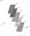
- an active electronically scanned array (AESA) antenna 10 is provided and includes a radome 12, a radiator aperture assembly 13, a plate 14, which serves as a corporate feed or a power divider, a coldwall 15, transmit/receive (T/R) modules 16, a motherboard 17 and an aft cover (not shown).
- the radome 12 forms a forward end of the antenna 10 whereby electromagnetic radiation is transmitted or received.
- the aft cover forms an aft end of the antenna 10 in which the T/R modules 16 and the motherboard 17 are disposed to perform certain electronic functions.
- the motherboard 17 provides a DC signal and power distribution network by which the T/R modules 16 can be controlled.
- the radiator aperture assembly 13, the plate 14 and the coldwall 15 are operably disposed between the forward and aft ends of the antenna 10.
- the antenna 10 as a whole can have a rectangular shape with the radiator aperture assembly 13 having a similarly rectangular shape. This is not required, however, and it is to be understood that the antenna 10 can have various overall shapes with the radiator aperture assembly having similar or different shapes as well.
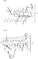
- each radiator stick 20 includes a body 200 that is formed of a radiator cover 21, a plurality of circulators 22, a radiator base 23 and a plurality of pairs of coax connectors 24.
- the pairs of coax connectors 24 may each have two offset coax connectors 241, two straight coax connectors 242 (see FIG. 4 ) or an offset coax connector 241 and a straight coax connector 242.
- the radiator cover 21 has a body 210 with a forward section 211 and an aft section 212 (see FIG. 3 ).
- the forward section 211 is generally rectangular in cross-section whereas the aft section 212 is frusto-conical in cross-section.
- the forward section 210 is narrower than the narrow end of the aft section 213 while the wide end of the aft section 213 has a substantially similar width as that of the radiator base 23.
- a series of substantially circular holes 25 and elongate holes 26 are defined through the radiator cover 21 along a longitudinal length thereof.
- the substantially circular holes 25 align with corresponding fastener holes 27 of the radiator base 23 such that fastening elements, such as screws, can be threadably inserted to attach the radiator cover 21 to the radiator base 23.
- the elongate holes 26 permit the plurality of the circulators 22 to be respectively fastened to the radiator cover 21 or the radiator base 23 in accordance with known methods.
- the radiator base 23 has a body 230 that is substantially rectangular in cross-section and is formed to define the fastener holes 27 and recesses 231 between sequential fastener holes 27.
- the fastener holes 27 align with corresponding substantially circular holes 25 and the recesses 231 align with locations of the circulators 22.
- the body 230 is further formed to define pairs of offset coax connector through holes 233, pairs of straight coax connector through-holes or pairs of a straight coax connector through-hole and an offset coax connector through-hole 233 within each one of the recesses 231.
- the straight coax connector through-holes and the offset coax connector through holes 233 are located such that they align with corresponding transmission and reception ports 224 and 225 of the circulators 22 (see FIG. 5 ).
- Each of the straight coax connector through holes is formed to extend in a generally straight line through the body 230 in accordance with a shape of the straight coax connectors 242.
- the offset coax connector through holes 233 are each elongated in accordance with a shape of the offset coax connectors 241.
- each of the circulators 22 includes a substrate 220 and a permanent magnet 226.
- the substrate 220 has a probe portion 221 at which an antenna port 222 is defined and a circulator portion 223 at which the transmission and reception ports 224 and 225 are respectively defined.
- the circulator portion 222 separates outbound waves from inbound waves and routs them from the transmission port 224 or to the reception port 225.
- the probe portion 221 couples waves traveling in a microstrip transmission line at the antenna port 222 to waves propagating in free space.
- each of the transmission ports 224, the reception ports 225 and the permanent magnets 226 face toward a corresponding one of the recesses 231.
- the radiator base 23 is attached to the radiator cover 21 with the straight coax connectors 242 received in the straight coax connector through-holes and/or the offset coax connectors 241 received in the offset coax connector through-holes 233, the circulators 22 sit within the recesses 231, the coax connectors (straight or offset) electrically couple with the transmission ports 224 and/or the reception portions 225.
- the circulators 22 may be fastened to the radiator cover 21 as noted above or to the radiator base 23.
- a plurality of radiator sticks 20 may be formed as described above and subsequently installed onto the plate 14 during a second stage of the antenna 10 assembly process.
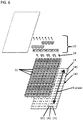
- the plate 14 has a generally planar body 140 with at least one planar surface 143 in which pairs of transmission and reception holes 141 and additional fastener holes 142 are formed.
- the straight coax connectors 242 and the offset coax connectors 241 are extendible through the transmission and reception holes 141 while the additional fastener holes 142 align with the corresponding fastener holes 27 and the corresponding circular holes 25 such that the fastening elements that attach the radiator cover 21 to the radiator base 23 can also attach the radiator sticks 20 to the plate 14.
- the radiator sticks 20 are installed with an orthogonal orientation relative to the E-plane of the plate 14, which provides for advantages that will be discussed in detail below.
- a first advantage is that the radiator sticks 20 permit attachment of a number of coax connectors with the plate 14 that is small enough (i.e., less than 1000s of simultaneous connections) to be achievable and large enough (i.e., more than 1 connection at a time) to be efficient.
- a second advantage is that the radiator sticks 20 extend along a long direction of the plate 14, which allows for an increased number of coax connections per radiator stick 20.
- a third advantage is that the arrangement of the transmission and reception holes 141 around the additional fastener holes 142 permits a mirrored arrangement of the circulators 22.
- a pair of circulators 22 may be provided on either side of a circular hole 25 (such that the circulators 22 would also be provided on either side of a fastener hole 27 and an additional fastener hole 142).
- the circulator 22 on the left side of the circular hole 25 in FIG. 5 has a permanent magnet 226 of a first polarity with a transmission port 224 and a reception port 225 proximate to the circular hole 25.
- the circulator 22 on the right side of the circular hole 25 in FIG. 5 has a permanent magnet 226 of a second polarity, which is opposite the first polarity, with a transmission port 224 and a reception port 225 similarly proximate to the circular hole 25.
- the coldwall 15 includes circuitry for connection to each of the straight coax connectors 242 and each of the offset coax connectors 241. This circuitry is itself configured for electrical coupling with corresponding circuitry of the T/R modules 16.
- the planar surface 143 of the plate 14 and complementary opposite sides of the radiator cover 21 and the radiator base 23 of each pair of adjacent radiator sticks 20 cooperatively form a long radiator slot 30 that extends forwardly away from the surface 143 of the plate 14.
- the respective probe portion 221 of each circulator 22 extends into the radiator slot 30 formed adjacent to its corresponding radiator stick 20 such that the corresponding antenna port 222 (see FIG. 5 ) can interact with waves propagating in the free space.
- each radiator slot 30 has a straight, relatively narrow aft portion 31 through which the probe portions 221 partially extend, a chamfered and notched portion 32 just forward from the probe portions 221 and a straight, relatively wide forward portion 33.
- the straight, relatively narrow aft portion 31 has a substantially uniform width with increasing distance forward from the surface 143.
- the probe portions 221 partially extend through a forward end of the straight, relatively narrow aft portion 31 such that distal ends of the probe portions 221 are slightly displaced from a side of the adjacent radiator base 23.
- the chamfered and notched portion 32 is formed just forward from the probe portions 221 and is defined by the effective chamfering and notching of the aft section 213 of the radiator cover 21, which has the frusto-conical cross-section.
- the straight, relatively wide forward portion 33 is wider than the straight, relatively narrow aft portion 31 and has a substantially uniform width with increasing distance forward from the surface 143.
- the shape of the slots 30 leads to reduced RF losses and improves antenna gain. These reduced RF losses and improved antenna gain represent another advantage of the configuration described herein.
- each coax connector may be provided as an offset coax connector 241 or a straight coax connector 242 in offset pairs, straight pairs or mixed pairs.
- the radiator base 23 is formed to define offset connector through-holes 233 or straight coax connector through-holes as required and the configurations of the transmission and reception ports 224, 225 of the circulators 22 are correspondingly modified.
- the determination of which configuration is to be used may be made in accordance with various factors, such as costs and the type of antenna array being employed (i.e., the HTM-4, F-15, RACR and APG-79 International module configurations and ISR platforms).
Landscapes
- Variable-Direction Aerials And Aerial Arrays (AREA)
- Waveguide Aerials (AREA)
Claims (7)
- Antenne, umfassend:eine Strahler-Öffnungsbaugruppe, die mehrere Strahlerstäbe (20) beinhaltet, wobei jeder Strahlerstab (20) eine Zeile von Strahlungselementen, die dazu gestaltet sind, RF-Energie zu senden und zu empfangen, und einen Körper (200) mit gegenüberliegenden Seiten beinhaltet, wobei leitende Elemente (24, 241, 242) mit den Strahlungselementen gekoppelt sind, undeine Platte (14), die nahe der Strahler-Öffnungsbaugruppe angeordnet ist, durch die sich die leitenden Elemente erstrecken,wobei komplementäre gegenüberliegende Seiten der jeweiligen Körper benachbarter Strahlerstäbe (20) und eine Oberfläche der Platte derart gestaltet sind, dass sie einen Schlitzstrahler (30) bilden, wobei jedes Strahlungselement einen Zirkulator (22) umfasst, der einen Sondenabschnitt (221) umfasst,wobei jedes Strahlungselement sich in den Schlitzstrahler (30) erstreckt, der benachbart zu seinem entsprechenden Strahlerstab (20) gebildet ist,wobei der Schlitzstrahler (30) Folgendes umfasst:eine ebene Oberfläche (143) an der Oberfläche der Platte,einen schmalen hinteren Abschnitt (31) nahe der Oberfläche der Platte,einen breiten vorderen Abschnitt (33) fern der Oberfläche der Platte undeinen abgeschrägten und gekerbten Abschnitt (32), der zwischen dem schmalen hinteren und dem breiten vorderen Abschnitt definiert ist, wobei der schmale hintere Abschnitt (31) gerade ist und wobei der Sondenabschnitt (221) des Zirkulators (22) jedes Strahlungselements sich teilweise durch ein vorderes Ende des jeweiligen geraden schmalen hinteren Abschnitts (31) derart erstreckt, dass ein distales Ende des Sondenabschnitts (221) leicht zur komplementären gegenüberliegenden Seite des Körpers des jeweiligen benachbarten Strahlerstabs (20) versetzt ist.
- Antenne nach Anspruch 1, wobei der schmale hintere Abschnitt (31) und der breite vordere Abschnitt (33) jeweils eine im Wesentlichen gleichmäßige Dicke zwischen den komplementären gegenüberliegenden Seiten der jeweiligen Körper der benachbarten Strahlerstäbe aufweisen.
- Antenne nach Anspruch 2, wobei der abgeschrägte und gekerbte Abschnitt (32) ein schmales hinteres Ende, das eine im Wesentlichen ähnliche Dicke wie der schmale hintere Abschnitt aufweist, und ein breites Ende aufweist, das sich in Bezug auf den Schlitzstrahler (30) seitlich verbreitert.
- Antenne nach Anspruch 1, wobei benachbarte Zirkulatoren (22) gespiegelt sind.
- Antenne nach Anspruch 1, wobei die Strahlerstäbe (20) eine rechtwinklige Ausrichtung in Bezug auf eine E-Ebene der Platte aufweisen.
- Antenne nach Anspruch 1, wobei die leitenden Elemente Paare von versetzten leitenden Elementen (241) aufweisen.
- Antenne nach Anspruch 1, wobei die Platte (14) derart gebildet ist, dass sie Befestigungslöcher und gegenüberliegende Paare von Sendelöchern an jeder Seite jedes der Befestigungslöcher definieren.
Applications Claiming Priority (2)
| Application Number | Priority Date | Filing Date | Title |
|---|---|---|---|
| US13/483,404 US9685707B2 (en) | 2012-05-30 | 2012-05-30 | Active electronically scanned array antenna |
| PCT/US2013/034269 WO2013180828A1 (en) | 2012-05-30 | 2013-03-28 | Active electronically scanned array antenna |
Publications (3)
| Publication Number | Publication Date |
|---|---|
| EP2856557A1 EP2856557A1 (de) | 2015-04-08 |
| EP2856557A4 EP2856557A4 (de) | 2016-01-13 |
| EP2856557B1 true EP2856557B1 (de) | 2021-01-13 |
Family
ID=49669556
Family Applications (1)
| Application Number | Title | Priority Date | Filing Date |
|---|---|---|---|
| EP13796807.9A Active EP2856557B1 (de) | 2012-05-30 | 2013-03-28 | Aktive elektronisch geschwenkte gruppenantenne |
Country Status (5)
| Country | Link |
|---|---|
| US (1) | US9685707B2 (de) |
| EP (1) | EP2856557B1 (de) |
| IL (1) | IL235926B (de) |
| TW (1) | TWI549367B (de) |
| WO (1) | WO2013180828A1 (de) |
Families Citing this family (13)
| Publication number | Priority date | Publication date | Assignee | Title |
|---|---|---|---|---|
| US9685707B2 (en) | 2012-05-30 | 2017-06-20 | Raytheon Company | Active electronically scanned array antenna |
| US9876283B2 (en) * | 2014-06-19 | 2018-01-23 | Raytheon Company | Active electronically scanned array antenna |
| CA2980920C (en) | 2015-03-25 | 2023-09-26 | King Abdulaziz City Of Science And Technology | Apparatus and methods for synthetic aperture radar with digital beamforming |
| WO2017044168A2 (en) * | 2015-06-16 | 2017-03-16 | King Abdulaziz City Of Science And Technology | Efficient planar phased array antenna assembly |
| EP3380864A4 (de) | 2015-11-25 | 2019-07-03 | Urthecast Corp. | Radarbildgebungsvorrichtung mit synthetischer apertur und verfahren |
| DE102016201978B4 (de) | 2016-02-10 | 2018-09-06 | National Chung Shan Institute Of Science And Technology | Antennenvorrichtung und Antennengruppenvorrichtung für Millimeterwellen |
| US10116064B2 (en) | 2016-02-16 | 2018-10-30 | National Chung Shan Institute Of Science And Technology | Millimeter-wave antenna device and millimeter-wave antenna array device thereof |
| EP3631504B8 (de) | 2017-05-23 | 2023-08-16 | Spacealpha Insights Corp. | Radarbildgebungsvorrichtung mit synthetischer apertur und verfahren |
| WO2018217902A1 (en) | 2017-05-23 | 2018-11-29 | King Abdullah City Of Science And Technology | Synthetic aperture radar imaging apparatus and methods for moving targets |
| CA3083033A1 (en) | 2017-11-22 | 2019-11-28 | Urthecast Corp. | Synthetic aperture radar apparatus and methods |
| US11205856B2 (en) | 2019-08-09 | 2021-12-21 | Raytheon Company | Compact long slot antenna |
| RU2763110C1 (ru) * | 2021-05-04 | 2021-12-27 | Игорь Борисович Широков | Активная приемопередающая антенна Широкова |
| US11870142B2 (en) * | 2021-09-17 | 2024-01-09 | Raytheon Company | Tile to tile RF grounding |
Citations (5)
| Publication number | Priority date | Publication date | Assignee | Title |
|---|---|---|---|---|
| EP0455493A2 (de) * | 1990-05-04 | 1991-11-06 | Motorola, Inc. | Antenne mit sich erweiterndem Schlitz |
| WO2001056114A1 (fr) * | 2000-01-27 | 2001-08-02 | Tokimec Inc. | Antenne tige dielectrique |
| JP2003152433A (ja) * | 2001-11-09 | 2003-05-23 | Mitsubishi Electric Corp | アンテナ装置 |
| US20070126648A1 (en) * | 2003-12-30 | 2007-06-07 | Telefonaktiebolaget Lm Ericsson | Antenna device and array antenna |
| WO2013106144A1 (en) * | 2012-01-11 | 2013-07-18 | Raytheon Company | Low profile cavity backed long slot array antenna with integrated circulators |
Family Cites Families (28)
| Publication number | Priority date | Publication date | Assignee | Title |
|---|---|---|---|---|
| US3935548A (en) | 1974-06-04 | 1976-01-27 | The Washington University | Wide-band microwave circulator |
| GB8619680D0 (en) * | 1986-08-13 | 1986-09-24 | Collins J L F C | Flat plate array |
| US5086304A (en) * | 1986-08-13 | 1992-02-04 | Integrated Visual, Inc. | Flat phased array antenna |
| JPS63305538A (ja) | 1987-06-05 | 1988-12-13 | Fujitsu Ltd | Lcc一括接合用治具 |
| EP0802578A4 (de) * | 1994-06-09 | 2000-12-20 | Zakrytoe Aktionernoe Obschestv | Planare gruppenantenne und zugehörige mikrostreiferleiter-strahlerelemente |
| US5703599A (en) | 1996-02-26 | 1997-12-30 | Hughes Electronics | Injection molded offset slabline RF feedthrough for active array aperture interconnect |
| US6127984A (en) | 1999-04-16 | 2000-10-03 | Raytheon Company | Flared notch radiator assembly and antenna |
| US6219000B1 (en) | 1999-08-10 | 2001-04-17 | Raytheon Company | Flared-notch radiator with improved cross-polarization absorption characteristics |
| EP1372186B1 (de) * | 2000-10-31 | 2008-12-10 | Sez Ag | Vorrichtung zur Flüssigkeitsbehandlung von scheibenförmigen Gegenständen |
| US6480167B2 (en) * | 2001-03-08 | 2002-11-12 | Gabriel Electronics Incorporated | Flat panel array antenna |
| US6388631B1 (en) | 2001-03-19 | 2002-05-14 | Hrl Laboratories Llc | Reconfigurable interleaved phased array antenna |
| US6653984B2 (en) | 2001-04-05 | 2003-11-25 | Raytheon Company | Electronically scanned dielectric covered continuous slot antenna conformal to the cone for dual mode seeker |
| US6600453B1 (en) | 2002-01-31 | 2003-07-29 | Raytheon Company | Surface/traveling wave suppressor for antenna arrays of notch radiators |
| US6778145B2 (en) * | 2002-07-03 | 2004-08-17 | Northrop Grumman Corporation | Wideband antenna with tapered surfaces |
| US6781554B2 (en) | 2002-08-14 | 2004-08-24 | Raytheon Company | Compact wide scan periodically loaded edge slot waveguide array |
| US7057570B2 (en) | 2003-10-27 | 2006-06-06 | Raytheon Company | Method and apparatus for obtaining wideband performance in a tapered slot antenna |
| US7315288B2 (en) | 2004-01-15 | 2008-01-01 | Raytheon Company | Antenna arrays using long slot apertures and balanced feeds |
| US7057563B2 (en) * | 2004-05-28 | 2006-06-06 | Raytheon Company | Radiator structures |
| US7109943B2 (en) * | 2004-10-21 | 2006-09-19 | The Boeing Company | Structurally integrated antenna aperture and fabrication method |
| US7417598B2 (en) * | 2006-11-08 | 2008-08-26 | The Boeing Company | Compact, low profile electronically scanned antenna |
| US7764236B2 (en) * | 2007-01-04 | 2010-07-27 | Apple Inc. | Broadband antenna for handheld devices |
| US7889147B2 (en) * | 2007-02-23 | 2011-02-15 | Northrop Grumman Systems Corporation | Modular active phased array |
| WO2009005912A2 (en) | 2007-05-30 | 2009-01-08 | Massachusetts Institute Of Technology | Notch antenna having a low profile stripline feed |
| US8232928B2 (en) * | 2008-06-23 | 2012-07-31 | Raytheon Company | Dual-polarized antenna array |
| IL197906A (en) * | 2009-04-05 | 2014-09-30 | Elta Systems Ltd | Antenna arrays and method for creating them |
| EP2622686B1 (de) | 2010-10-01 | 2018-03-21 | Saab AB | Montagesystem für sender-empfänger-module |
| GB2498546B (en) | 2012-01-18 | 2015-07-22 | Thales Holdings Uk Plc | Horn antenna |
| US9685707B2 (en) | 2012-05-30 | 2017-06-20 | Raytheon Company | Active electronically scanned array antenna |
-
2012
- 2012-05-30 US US13/483,404 patent/US9685707B2/en active Active
-
2013
- 2013-03-28 EP EP13796807.9A patent/EP2856557B1/de active Active
- 2013-03-28 TW TW102111118A patent/TWI549367B/zh active
- 2013-03-28 WO PCT/US2013/034269 patent/WO2013180828A1/en not_active Ceased
-
2014
- 2014-11-26 IL IL235926A patent/IL235926B/en active IP Right Grant
Patent Citations (6)
| Publication number | Priority date | Publication date | Assignee | Title |
|---|---|---|---|---|
| EP0455493A2 (de) * | 1990-05-04 | 1991-11-06 | Motorola, Inc. | Antenne mit sich erweiterndem Schlitz |
| WO2001056114A1 (fr) * | 2000-01-27 | 2001-08-02 | Tokimec Inc. | Antenne tige dielectrique |
| JP2003152433A (ja) * | 2001-11-09 | 2003-05-23 | Mitsubishi Electric Corp | アンテナ装置 |
| US20070126648A1 (en) * | 2003-12-30 | 2007-06-07 | Telefonaktiebolaget Lm Ericsson | Antenna device and array antenna |
| WO2013106144A1 (en) * | 2012-01-11 | 2013-07-18 | Raytheon Company | Low profile cavity backed long slot array antenna with integrated circulators |
| EP2803111A1 (de) * | 2012-01-11 | 2014-11-19 | Raytheon Company | Durch einen hohlraum mit niedrigem profil gestützte langschlitzgruppenantenne mit integrierten zirkulatoren |
Also Published As
| Publication number | Publication date |
|---|---|
| WO2013180828A1 (en) | 2013-12-05 |
| US9685707B2 (en) | 2017-06-20 |
| IL235926B (en) | 2018-06-28 |
| TW201349666A (zh) | 2013-12-01 |
| IL235926A0 (en) | 2015-01-29 |
| EP2856557A4 (de) | 2016-01-13 |
| TWI549367B (zh) | 2016-09-11 |
| EP2856557A1 (de) | 2015-04-08 |
| US20130321228A1 (en) | 2013-12-05 |
Similar Documents
| Publication | Publication Date | Title |
|---|---|---|
| EP2856557B1 (de) | Aktive elektronisch geschwenkte gruppenantenne | |
| US6864851B2 (en) | Low profile wideband antenna array | |
| CN108370100B (zh) | 具有单平面带状线馈电的双极化宽频带辐射器 | |
| US6552691B2 (en) | Broadband dual-polarized microstrip notch antenna | |
| EP3235059B1 (de) | Oberflächenmontiertes breitbandelement | |
| EP3479437B1 (de) | Gruppenantenne | |
| US9401545B2 (en) | Multi polarization conformal channel monopole antenna | |
| EP2803111B1 (de) | Durch einen hohlraum mit niedrigem profil gestützte langschlitzgruppenantenne mit integrierten zirkulatoren | |
| WO2014121212A1 (en) | Notch-antenna array and method of making same | |
| EP2124292A2 (de) | Reflexionsantenne | |
| US6407722B1 (en) | Choke coupled coaxial connector | |
| US6351244B1 (en) | Arrangement for use in an antenna array for transmitting and receiving at at least one frequency in at least two polarizations | |
| US7287987B2 (en) | Electrical connector apparatus and method | |
| EP3047538A1 (de) | Über einen kurzen koinzidierenden phasengesteuerten slot gespeiste dualpolarisierte apertur | |
| KR101866170B1 (ko) | 능동 전자 주사 위상배열 안테나 | |
| KR100706615B1 (ko) | 다층 유전체기판을 이용한 마이크로스트립 패치 안테나 및이를 이용한 배열 안테나 | |
| KR101799866B1 (ko) | 테이퍼드 슬롯 안테나 및 이를 구비하는 평면배열 안테나 모듈 | |
| US10530065B2 (en) | Waveguide radiating element and method for making the same | |
| WO1992012547A1 (en) | Microwave connector |
Legal Events
| Date | Code | Title | Description |
|---|---|---|---|
| PUAI | Public reference made under article 153(3) epc to a published international application that has entered the european phase |
Free format text: ORIGINAL CODE: 0009012 |
|
| 17P | Request for examination filed |
Effective date: 20141211 |
|
| AK | Designated contracting states |
Kind code of ref document: A1 Designated state(s): AL AT BE BG CH CY CZ DE DK EE ES FI FR GB GR HR HU IE IS IT LI LT LU LV MC MK MT NL NO PL PT RO RS SE SI SK SM TR |
|
| AX | Request for extension of the european patent |
Extension state: BA ME |
|
| DAX | Request for extension of the european patent (deleted) | ||
| RA4 | Supplementary search report drawn up and despatched (corrected) |
Effective date: 20151215 |
|
| RIC1 | Information provided on ipc code assigned before grant |
Ipc: H01Q 13/08 20060101ALI20151209BHEP Ipc: H01Q 21/10 20060101ALI20151209BHEP Ipc: H01Q 21/06 20060101ALI20151209BHEP Ipc: H01Q 19/22 20060101ALI20151209BHEP Ipc: H01Q 13/10 20060101AFI20151209BHEP Ipc: H01Q 21/00 20060101ALI20151209BHEP |
|
| STAA | Information on the status of an ep patent application or granted ep patent |
Free format text: STATUS: EXAMINATION IS IN PROGRESS |
|
| 17Q | First examination report despatched |
Effective date: 20190513 |
|
| REG | Reference to a national code |
Ref country code: DE Ref legal event code: R079 Ref document number: 602013075312 Country of ref document: DE Free format text: PREVIOUS MAIN CLASS: H01Q0013100000 Ipc: H01Q0013080000 |
|
| GRAP | Despatch of communication of intention to grant a patent |
Free format text: ORIGINAL CODE: EPIDOSNIGR1 |
|
| STAA | Information on the status of an ep patent application or granted ep patent |
Free format text: STATUS: GRANT OF PATENT IS INTENDED |
|
| RIC1 | Information provided on ipc code assigned before grant |
Ipc: H01Q 13/08 20060101AFI20200622BHEP Ipc: H01Q 21/00 20060101ALI20200622BHEP Ipc: H01Q 21/06 20060101ALI20200622BHEP |
|
| INTG | Intention to grant announced |
Effective date: 20200729 |
|
| GRAS | Grant fee paid |
Free format text: ORIGINAL CODE: EPIDOSNIGR3 |
|
| GRAA | (expected) grant |
Free format text: ORIGINAL CODE: 0009210 |
|
| STAA | Information on the status of an ep patent application or granted ep patent |
Free format text: STATUS: THE PATENT HAS BEEN GRANTED |
|
| AK | Designated contracting states |
Kind code of ref document: B1 Designated state(s): AL AT BE BG CH CY CZ DE DK EE ES FI FR GB GR HR HU IE IS IT LI LT LU LV MC MK MT NL NO PL PT RO RS SE SI SK SM TR |
|
| REG | Reference to a national code |
Ref country code: GB Ref legal event code: FG4D |
|
| REG | Reference to a national code |
Ref country code: CH Ref legal event code: EP |
|
| REG | Reference to a national code |
Ref country code: IE Ref legal event code: FG4D |
|
| REG | Reference to a national code |
Ref country code: DE Ref legal event code: R096 Ref document number: 602013075312 Country of ref document: DE |
|
| REG | Reference to a national code |
Ref country code: AT Ref legal event code: REF Ref document number: 1355243 Country of ref document: AT Kind code of ref document: T Effective date: 20210215 |
|
| REG | Reference to a national code |
Ref country code: SE Ref legal event code: TRGR |
|
| REG | Reference to a national code |
Ref country code: AT Ref legal event code: MK05 Ref document number: 1355243 Country of ref document: AT Kind code of ref document: T Effective date: 20210113 |
|
| REG | Reference to a national code |
Ref country code: NL Ref legal event code: MP Effective date: 20210113 |
|
| REG | Reference to a national code |
Ref country code: LT Ref legal event code: MG9D |
|
| PG25 | Lapsed in a contracting state [announced via postgrant information from national office to epo] |
Ref country code: NL Free format text: LAPSE BECAUSE OF FAILURE TO SUBMIT A TRANSLATION OF THE DESCRIPTION OR TO PAY THE FEE WITHIN THE PRESCRIBED TIME-LIMIT Effective date: 20210113 Ref country code: NO Free format text: LAPSE BECAUSE OF FAILURE TO SUBMIT A TRANSLATION OF THE DESCRIPTION OR TO PAY THE FEE WITHIN THE PRESCRIBED TIME-LIMIT Effective date: 20210413 Ref country code: BG Free format text: LAPSE BECAUSE OF FAILURE TO SUBMIT A TRANSLATION OF THE DESCRIPTION OR TO PAY THE FEE WITHIN THE PRESCRIBED TIME-LIMIT Effective date: 20210413 Ref country code: PT Free format text: LAPSE BECAUSE OF FAILURE TO SUBMIT A TRANSLATION OF THE DESCRIPTION OR TO PAY THE FEE WITHIN THE PRESCRIBED TIME-LIMIT Effective date: 20210513 Ref country code: LT Free format text: LAPSE BECAUSE OF FAILURE TO SUBMIT A TRANSLATION OF THE DESCRIPTION OR TO PAY THE FEE WITHIN THE PRESCRIBED TIME-LIMIT Effective date: 20210113 Ref country code: HR Free format text: LAPSE BECAUSE OF FAILURE TO SUBMIT A TRANSLATION OF THE DESCRIPTION OR TO PAY THE FEE WITHIN THE PRESCRIBED TIME-LIMIT Effective date: 20210113 Ref country code: FI Free format text: LAPSE BECAUSE OF FAILURE TO SUBMIT A TRANSLATION OF THE DESCRIPTION OR TO PAY THE FEE WITHIN THE PRESCRIBED TIME-LIMIT Effective date: 20210113 Ref country code: GR Free format text: LAPSE BECAUSE OF FAILURE TO SUBMIT A TRANSLATION OF THE DESCRIPTION OR TO PAY THE FEE WITHIN THE PRESCRIBED TIME-LIMIT Effective date: 20210414 |
|
| PG25 | Lapsed in a contracting state [announced via postgrant information from national office to epo] |
Ref country code: RS Free format text: LAPSE BECAUSE OF FAILURE TO SUBMIT A TRANSLATION OF THE DESCRIPTION OR TO PAY THE FEE WITHIN THE PRESCRIBED TIME-LIMIT Effective date: 20210113 Ref country code: LV Free format text: LAPSE BECAUSE OF FAILURE TO SUBMIT A TRANSLATION OF THE DESCRIPTION OR TO PAY THE FEE WITHIN THE PRESCRIBED TIME-LIMIT Effective date: 20210113 Ref country code: PL Free format text: LAPSE BECAUSE OF FAILURE TO SUBMIT A TRANSLATION OF THE DESCRIPTION OR TO PAY THE FEE WITHIN THE PRESCRIBED TIME-LIMIT Effective date: 20210113 Ref country code: AT Free format text: LAPSE BECAUSE OF FAILURE TO SUBMIT A TRANSLATION OF THE DESCRIPTION OR TO PAY THE FEE WITHIN THE PRESCRIBED TIME-LIMIT Effective date: 20210113 |
|
| PG25 | Lapsed in a contracting state [announced via postgrant information from national office to epo] |
Ref country code: IS Free format text: LAPSE BECAUSE OF FAILURE TO SUBMIT A TRANSLATION OF THE DESCRIPTION OR TO PAY THE FEE WITHIN THE PRESCRIBED TIME-LIMIT Effective date: 20210513 |
|
| REG | Reference to a national code |
Ref country code: DE Ref legal event code: R097 Ref document number: 602013075312 Country of ref document: DE |
|
| PG25 | Lapsed in a contracting state [announced via postgrant information from national office to epo] |
Ref country code: MC Free format text: LAPSE BECAUSE OF FAILURE TO SUBMIT A TRANSLATION OF THE DESCRIPTION OR TO PAY THE FEE WITHIN THE PRESCRIBED TIME-LIMIT Effective date: 20210113 Ref country code: CZ Free format text: LAPSE BECAUSE OF FAILURE TO SUBMIT A TRANSLATION OF THE DESCRIPTION OR TO PAY THE FEE WITHIN THE PRESCRIBED TIME-LIMIT Effective date: 20210113 Ref country code: EE Free format text: LAPSE BECAUSE OF FAILURE TO SUBMIT A TRANSLATION OF THE DESCRIPTION OR TO PAY THE FEE WITHIN THE PRESCRIBED TIME-LIMIT Effective date: 20210113 Ref country code: SM Free format text: LAPSE BECAUSE OF FAILURE TO SUBMIT A TRANSLATION OF THE DESCRIPTION OR TO PAY THE FEE WITHIN THE PRESCRIBED TIME-LIMIT Effective date: 20210113 |
|
| REG | Reference to a national code |
Ref country code: CH Ref legal event code: PL |
|
| PLBE | No opposition filed within time limit |
Free format text: ORIGINAL CODE: 0009261 |
|
| STAA | Information on the status of an ep patent application or granted ep patent |
Free format text: STATUS: NO OPPOSITION FILED WITHIN TIME LIMIT |
|
| PG25 | Lapsed in a contracting state [announced via postgrant information from national office to epo] |
Ref country code: DK Free format text: LAPSE BECAUSE OF FAILURE TO SUBMIT A TRANSLATION OF THE DESCRIPTION OR TO PAY THE FEE WITHIN THE PRESCRIBED TIME-LIMIT Effective date: 20210113 Ref country code: ES Free format text: LAPSE BECAUSE OF FAILURE TO SUBMIT A TRANSLATION OF THE DESCRIPTION OR TO PAY THE FEE WITHIN THE PRESCRIBED TIME-LIMIT Effective date: 20210113 Ref country code: SK Free format text: LAPSE BECAUSE OF FAILURE TO SUBMIT A TRANSLATION OF THE DESCRIPTION OR TO PAY THE FEE WITHIN THE PRESCRIBED TIME-LIMIT Effective date: 20210113 Ref country code: RO Free format text: LAPSE BECAUSE OF FAILURE TO SUBMIT A TRANSLATION OF THE DESCRIPTION OR TO PAY THE FEE WITHIN THE PRESCRIBED TIME-LIMIT Effective date: 20210113 |
|
| REG | Reference to a national code |
Ref country code: BE Ref legal event code: MM Effective date: 20210331 |
|
| 26N | No opposition filed |
Effective date: 20211014 |
|
| PG25 | Lapsed in a contracting state [announced via postgrant information from national office to epo] |
Ref country code: IE Free format text: LAPSE BECAUSE OF NON-PAYMENT OF DUE FEES Effective date: 20210328 Ref country code: LU Free format text: LAPSE BECAUSE OF NON-PAYMENT OF DUE FEES Effective date: 20210328 Ref country code: LI Free format text: LAPSE BECAUSE OF NON-PAYMENT OF DUE FEES Effective date: 20210331 Ref country code: CH Free format text: LAPSE BECAUSE OF NON-PAYMENT OF DUE FEES Effective date: 20210331 Ref country code: AL Free format text: LAPSE BECAUSE OF FAILURE TO SUBMIT A TRANSLATION OF THE DESCRIPTION OR TO PAY THE FEE WITHIN THE PRESCRIBED TIME-LIMIT Effective date: 20210113 |
|
| PG25 | Lapsed in a contracting state [announced via postgrant information from national office to epo] |
Ref country code: SI Free format text: LAPSE BECAUSE OF FAILURE TO SUBMIT A TRANSLATION OF THE DESCRIPTION OR TO PAY THE FEE WITHIN THE PRESCRIBED TIME-LIMIT Effective date: 20210113 |
|
| PG25 | Lapsed in a contracting state [announced via postgrant information from national office to epo] |
Ref country code: IS Free format text: LAPSE BECAUSE OF FAILURE TO SUBMIT A TRANSLATION OF THE DESCRIPTION OR TO PAY THE FEE WITHIN THE PRESCRIBED TIME-LIMIT Effective date: 20210513 |
|
| PG25 | Lapsed in a contracting state [announced via postgrant information from national office to epo] |
Ref country code: BE Free format text: LAPSE BECAUSE OF NON-PAYMENT OF DUE FEES Effective date: 20210331 |
|
| PG25 | Lapsed in a contracting state [announced via postgrant information from national office to epo] |
Ref country code: HU Free format text: LAPSE BECAUSE OF FAILURE TO SUBMIT A TRANSLATION OF THE DESCRIPTION OR TO PAY THE FEE WITHIN THE PRESCRIBED TIME-LIMIT; INVALID AB INITIO Effective date: 20130328 |
|
| PG25 | Lapsed in a contracting state [announced via postgrant information from national office to epo] |
Ref country code: CY Free format text: LAPSE BECAUSE OF FAILURE TO SUBMIT A TRANSLATION OF THE DESCRIPTION OR TO PAY THE FEE WITHIN THE PRESCRIBED TIME-LIMIT Effective date: 20210113 |
|
| P01 | Opt-out of the competence of the unified patent court (upc) registered |
Effective date: 20230530 |
|
| PG25 | Lapsed in a contracting state [announced via postgrant information from national office to epo] |
Ref country code: MK Free format text: LAPSE BECAUSE OF FAILURE TO SUBMIT A TRANSLATION OF THE DESCRIPTION OR TO PAY THE FEE WITHIN THE PRESCRIBED TIME-LIMIT Effective date: 20210113 |
|
| PG25 | Lapsed in a contracting state [announced via postgrant information from national office to epo] |
Ref country code: MT Free format text: LAPSE BECAUSE OF FAILURE TO SUBMIT A TRANSLATION OF THE DESCRIPTION OR TO PAY THE FEE WITHIN THE PRESCRIBED TIME-LIMIT Effective date: 20210113 |
|
| PG25 | Lapsed in a contracting state [announced via postgrant information from national office to epo] |
Ref country code: TR Free format text: LAPSE BECAUSE OF FAILURE TO SUBMIT A TRANSLATION OF THE DESCRIPTION OR TO PAY THE FEE WITHIN THE PRESCRIBED TIME-LIMIT Effective date: 20210113 |
|
| PGFP | Annual fee paid to national office [announced via postgrant information from national office to epo] |
Ref country code: SE Payment date: 20260219 Year of fee payment: 14 |
|
| PGFP | Annual fee paid to national office [announced via postgrant information from national office to epo] |
Ref country code: GB Payment date: 20260219 Year of fee payment: 14 |
|
| PGFP | Annual fee paid to national office [announced via postgrant information from national office to epo] |
Ref country code: DE Payment date: 20260219 Year of fee payment: 14 |
|
| PGFP | Annual fee paid to national office [announced via postgrant information from national office to epo] |
Ref country code: IT Payment date: 20260219 Year of fee payment: 14 |
|
| PGFP | Annual fee paid to national office [announced via postgrant information from national office to epo] |
Ref country code: FR Payment date: 20260219 Year of fee payment: 14 |