EP2856243B1 - Verfahren zur helligkeitsverbesserung und modusmanipulation von multimodus-glasfasern - Google Patents
Verfahren zur helligkeitsverbesserung und modusmanipulation von multimodus-glasfasern Download PDFInfo
- Publication number
- EP2856243B1 EP2856243B1 EP13796685.9A EP13796685A EP2856243B1 EP 2856243 B1 EP2856243 B1 EP 2856243B1 EP 13796685 A EP13796685 A EP 13796685A EP 2856243 B1 EP2856243 B1 EP 2856243B1
- Authority
- EP
- European Patent Office
- Prior art keywords
- fiber
- phase
- modes
- electro
- applying
- Prior art date
- Legal status (The legal status is an assumption and is not a legal conclusion. Google has not performed a legal analysis and makes no representation as to the accuracy of the status listed.)
- Active
Links
Images







Classifications
-
- G—PHYSICS
- G02—OPTICS
- G02F—OPTICAL DEVICES OR ARRANGEMENTS FOR THE CONTROL OF LIGHT BY MODIFICATION OF THE OPTICAL PROPERTIES OF THE MEDIA OF THE ELEMENTS INVOLVED THEREIN; NON-LINEAR OPTICS; FREQUENCY-CHANGING OF LIGHT; OPTICAL LOGIC ELEMENTS; OPTICAL ANALOGUE/DIGITAL CONVERTERS
- G02F1/00—Devices or arrangements for the control of the intensity, colour, phase, polarisation or direction of light arriving from an independent light source, e.g. switching, gating or modulating; Non-linear optics
- G02F1/01—Devices or arrangements for the control of the intensity, colour, phase, polarisation or direction of light arriving from an independent light source, e.g. switching, gating or modulating; Non-linear optics for the control of the intensity, phase, polarisation or colour
- G02F1/03—Devices or arrangements for the control of the intensity, colour, phase, polarisation or direction of light arriving from an independent light source, e.g. switching, gating or modulating; Non-linear optics for the control of the intensity, phase, polarisation or colour based on ceramics or electro-optical crystals, e.g. exhibiting Pockels effect or Kerr effect
- G02F1/035—Devices or arrangements for the control of the intensity, colour, phase, polarisation or direction of light arriving from an independent light source, e.g. switching, gating or modulating; Non-linear optics for the control of the intensity, phase, polarisation or colour based on ceramics or electro-optical crystals, e.g. exhibiting Pockels effect or Kerr effect in an optical waveguide structure
-
- G—PHYSICS
- G02—OPTICS
- G02B—OPTICAL ELEMENTS, SYSTEMS OR APPARATUS
- G02B6/00—Light guides; Structural details of arrangements comprising light guides and other optical elements, e.g. couplings
- G02B6/10—Light guides; Structural details of arrangements comprising light guides and other optical elements, e.g. couplings of the optical waveguide type
- G02B6/14—Mode converters
-
- G—PHYSICS
- G02—OPTICS
- G02F—OPTICAL DEVICES OR ARRANGEMENTS FOR THE CONTROL OF LIGHT BY MODIFICATION OF THE OPTICAL PROPERTIES OF THE MEDIA OF THE ELEMENTS INVOLVED THEREIN; NON-LINEAR OPTICS; FREQUENCY-CHANGING OF LIGHT; OPTICAL LOGIC ELEMENTS; OPTICAL ANALOGUE/DIGITAL CONVERTERS
- G02F1/00—Devices or arrangements for the control of the intensity, colour, phase, polarisation or direction of light arriving from an independent light source, e.g. switching, gating or modulating; Non-linear optics
- G02F1/01—Devices or arrangements for the control of the intensity, colour, phase, polarisation or direction of light arriving from an independent light source, e.g. switching, gating or modulating; Non-linear optics for the control of the intensity, phase, polarisation or colour
- G02F1/011—Devices or arrangements for the control of the intensity, colour, phase, polarisation or direction of light arriving from an independent light source, e.g. switching, gating or modulating; Non-linear optics for the control of the intensity, phase, polarisation or colour in optical waveguides, not otherwise provided for in this subclass
- G02F1/0115—Devices or arrangements for the control of the intensity, colour, phase, polarisation or direction of light arriving from an independent light source, e.g. switching, gating or modulating; Non-linear optics for the control of the intensity, phase, polarisation or colour in optical waveguides, not otherwise provided for in this subclass in optical fibres
-
- H—ELECTRICITY
- H01—ELECTRIC ELEMENTS
- H01S—DEVICES USING THE PROCESS OF LIGHT AMPLIFICATION BY STIMULATED EMISSION OF RADIATION [LASER] TO AMPLIFY OR GENERATE LIGHT; DEVICES USING STIMULATED EMISSION OF ELECTROMAGNETIC RADIATION IN WAVE RANGES OTHER THAN OPTICAL
- H01S3/00—Lasers, i.e. devices using stimulated emission of electromagnetic radiation in the infrared, visible or ultraviolet wave range
- H01S3/05—Construction or shape of optical resonators; Accommodation of active medium therein; Shape of active medium
- H01S3/06—Construction or shape of active medium
- H01S3/063—Waveguide lasers, i.e. whereby the dimensions of the waveguide are of the order of the light wavelength
- H01S3/067—Fibre lasers
Definitions
- the present invention relates to optical fibers. More particularly the invention relates to a method for altering modal structure of light propagating in an optical fiber.
- Optical fibers are of great importance in many fields of science and technology. There are various parameters of optical fibers affecting their properties; one of the most important is the number of modes capable of non-attenuated propagation. Fibers carrying only a single transverse mode are called single mode (SM) fibers, Fibers capable of propagating more than one mode are called multimode fibers (MM). Different fiber modes have different propagation properties, e.g. group velocity, spatial intensity and phase profiles. Modal group velocity dependence in MM fibers affects the fiber's ability to transmit data along longer distances. Intensity and phase dependence affect the beam quality factor, i.e. the M 2 parameter, of the beam exiting the fiber. This is important in laser application of fibers, when the laser beam quality degrades due to higher fiber modes.
- M 2 parameter the beam quality factor
- Modal structure of the beam propagating in optical fiber depends on the beam intensity and phase profile at the fiber input.
- W. Q. Thornburg et al. "Selective launching of higher-order modes into an optical fiber with an optical phase shifter”.
- Optics Letters, Vol. 19, No. 7, 1994, pgs. 454-456 or output, one can change the modal structure of the exiting beam.
- a common technique for controlling the phase of an optical beam is adaptive optics ( Michael Bass - Editor in chief, Handbook of optics, Vol. 3, 2nd edition, 2001, pages 1.4-1.11 ).
- Adaptive optics is widely used in astronomical observations, where in order to achieve high resolution images, light phase should be dynamically compensated because of atmospheric turbulence distortions.
- Adaptive optics technology is based on sensing the incident beam phase by phase sensors and subsequent correction by an array of dynamic elements capable of altering the phase profile of the beam ( H. Babcock, "The possibility of compensating astronomical seeing", Publications of the Astronomical Society of the Pacific 65: 229-236, October, 1953 ).
- Phase altering arrays are based on piezoelectric actuated membrane mirrors or liquid crystal based phase masks.
- Adaptive optics technology has already made great impact in astronomical telescopes ( F. Roddier, "Adaptive Optics in Astronomy", Cambridge University Press, Cambridge, England, 1999, pages 1-9 ), retinal imaging systems ( E. N.
- US 7,194,155 describes using a free space spatial light modulator (SLM) to manipulate the modes at the entrance to the fiber.
- SLM free space spatial light modulator
- US 3,944,811 teaches a method to control the number of modes that can propagate in a waveguide.
- the invention is a method of lowering the number of higher modes in a multimode (MM) beam propagating in an MM fiber.
- the method comprises:
- the number of higher modes in the MM fiber is lowered by causing localized refractive index changes in at least one of the following ways:
- control feedback can be provided to the phase control actuators from a wavefront sensor by focusing the corrected beam with a focusing lens and determining the spot size.
- the MM fiber in which the phase correction takes place has a core diameter and the output light from the MM fiber is coupled to a fiber having a smaller core diameter without loss of power.
- the MM fiber in which the phase correction takes place is a pumping source and/or the gain medium of a fiber laser.
- the wavefront sensor may be comprised of a lenslet array and a CCD camera.
- the invention relates to adaptive optics techniques applied to alter the modal structure of light propagating in an optical fiber.
- the invention relates to altering the modal structure in a multimode beam propagating in an MM fiber by lowering the number of higher order modes.
- the method comprises combining a wavefront sensor with a phase control actuator and actuator control algorithms, to alter the phase structure of the beam thereby to eliminate higher order modes.
- the corrected beam can be then effectively coupled into a smaller diameter fiber with minimum loss of energy and concentrated to smaller spot sizes limited by diffraction.
- the population of the modes propagating within a multi-mode fiber can be controlled by introducing a local inhomogeneity in the index of refraction via mode mixing.
- this inhomogeneity is naturally occurring, via physical fiber deformations, for example, and causes the modes to mix.
- the present invention comprises introducing local controlled refractive index changes and, by monitoring the output electro-magnetic field intensity distribution, controlling the mode population in a closed feedback loop.
- the local index of refraction changes can be caused by many methods, for example by the following:
- a wavefront sensor is combined with a phase control actuator and actuator control algorithms to alter the phase structure of the beam in such a way that higher order modes are eliminated, thus improving the beam quality by significant factors up to the quality of a single mode beam.
- Two examples of suitable methods of feedback to actuators from phase sensors that can be used to measure the beam error in order to correct it comprise:
- the setup may include a multimode fiber-coupled collimated laser 10; in an example that does not form part of the invention a collimated beam 11 exiting the multimode fiber 12 can then be projected onto a deformable mirror 13 ( Figs. 3 and 4 ), which can be used as a phase altering device.
- a folding mirror 15 can be used for alignment purposes, and a beam splitter 16 can split the beam into two perpendicular paths 17 and 18.
- the reflected path 18 can be followed by Hartmann-Shack wavefront phase sensor 19 ( Figs. 3 and 5 ), utilizing a CCD camera 20 and a lenslet array 21.
- the phase distribution can be analyzed using image post-processing.
- the reflected path can be focused on a CCD camera 22 by a focusing lens 23 ( Figs. 4 and 6 ), employed in order to measure the spot size of the focused beam while performing modes manipulation; the forward path is used for the transmission of the output corrected beam.
- the present invention can be applied in all applications where the divergence (N.A.) of light within optical fibers, or keeping a low number of modes within a fiber of a given (typically, large) core diameter is of importance.
- Some examples of these applications are given below and illustrated schematically in the Fig.7 to Fig. 11 .
- the light is traveling from left to right, i.e. from many fibers to one single fiber (coupler) or from a large diameter fiber to a narrower one.
- the adaptive stage 100 on the main fiber is strain actuators 14 as shown in Figs. 5 and 6 .
- the adaptive stage 100 is a deformable mirror 13 as shown in Figs. 3 and 4 .
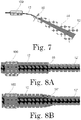
- Fig. 7 schematically shows the divergence of a beam 82 treated according to the invention as compared to an untreated beam 84 that exits fiber 12 and passes through collimating lens 80.
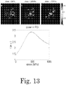
- Controlling the population of modes within an optical fiber makes the effective divergence and effective mode diameter of the light guided in the fiber (N.A.) smaller than the N.A. and mode diameter for which the fiber was designed. This allows coupling light from large core fibers 12 to fibers of smaller core 12' without loss of power. This can be done either by direct splice 86 or by a taper 86' to the fiber as shown in Fig. 8A and Fig. 8B respectively.
- the fibers are illustrated schematically by two shades of gray to represent the core and the cladding.
- the low effective N.A. and mode diameter of the mode-controlled fiber allows the making of efficient pumping sources for high power lasers, where the power is introduced through an adaptive stage 100. Such an arrangement is schematically shown in Fig. 9 .
- Fiber lasers need to have high brightness (low NA and effective mode diameter) to be effectively focused to small spot sizes.
- making fiber sources with small fiber cores, for a given N.A. is extremely challenging due to various technological difficulties, such as thermal and non-linear effects directly related to total power density, which is inverse squarely scaled with fiber core diameter.
- Large core fibers necessarily allow higher order modes to populate without significant losses.
- Fig. 10 Symbolically shown in Fig. 10 and Fig. 11 are seeder 88 and fiber grating mirrors 72 that create the laser cavity, while its modes population is optimized by the adaptive stage 100.
- High power fiber lasers have to have large core diameters in order to avoid fiber damage and non-linear effects due to high energy concentration.
- increasing the fiber power means increasing the core diameters and thus lowering the laser brightness.
- a population controlled active-fiber can have a large core and still be a very high brightness gain medium for a fiber laser.
- the combination of the high brightness pump modules and high brightness gain medium is shown schematically in Fig. 11 .
- ⁇ is random number ranging [-1, 1] with flat distribution and ⁇ is a constant defining the modal constitution of the beam.
- the beam segment is distorted by phase masks located at predefined positions z i with phase distortion of: where C o is the stress optical coefficient, ⁇ z is the stress longitudinal effective dimension and ⁇ is the average applied stress.
- the updated modal distribution of the disturbed field can be calculated by projecting the disturbed field distribution onto the basic fiber modes.
- the mode overlap integrals are evaluated as follows:
- ⁇ kl mn ⁇ ⁇ r c R T kl x y T mn x y e i ⁇ x y dxdy
- the updated ⁇ mn * mode coefficients are computed and the field is propagated to the next actuation point z i + 1.
- the following describes the convergence algorithm applied to determine the optimal set of applied stress values to a given set of actuators in order to minimize a certain merit function.
- Fig. 12 shows a stress distribution in a core/clad/polymer jacket optical fiber induced by mechanical actuation applied in the transverse direction on the fiber jacket.
- a typical elasto-optic coefficient C ⁇ of fused silica is 2.5x10 -12 Pa -1 .
- the effect on the fiber output field distribution is calculated and presented in Fig. 14 . This simulation shows that stress up to 1 GPa causes a significant modes mixing in multimode optical fiber.
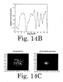
- the top three images in Fig. 13 show (from left to right) simulations of the light intensity at the multimode optical fiber output capable of carrying 100 transverse modes for an applied stress of 0MPa, 340MPa, and 660MPa respectively. Note a substantial intensity change in the speckles marked by the arrows in the left image.
- the graph at the bottom shows the mean intensity (in arbitrary units) in the region of interest (ROI) marked by the square in the images above.
- This example presents an implementation of brightness enhancement in a 100 ⁇ m core / NA 0.08 optical fiber typically used in higher power fiber lasers.
- the upper image in Fig. 14A shows an intensity distribution along a 15 mm propagation length in an undisturbed optical fiber.
- the lower three images show transverse intensity maps at three selected points.
- the transverse intensity maps show high random speckling resulting from modal dispersion.
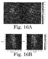
- Fig. 14B shows an intensity distribution at the fiber output without applied stress actuators (left image) and after the optimization of brightness (right image).
- Figure 14D shows (graph on the left) the effective beam quality of the light propagating within the fiber after each actuator, showing a progressive improvement after each actuator.
- the image on the right of Fig. 14D shows the modes composition of the light propagating in the fiber. This image shows that an optimized mixing of the modes transfers energy from higher order modes to lower order ones.
- FIG. 15A shows an intensity distribution at the fiber output without applied stress actuators (left image) and after the optimization of brightness according to the method of the invention (right image).
- Fig. 15B shows a typical convergence of the iterative algorithm described in example 1 herein above. Typically about 50 iterations are required for 90% convergence. This means that if a typical stress actuator can be operated at 2 kHz frequency and the detector can be sampled at this frequency as well, a total bandwidth of 40 Hz for the total correction can be achieved.
- Fig. 15C shows the beam quality improvement of the output radiation from 3 different optical fibers versus total number of actuators. It can be seen that a total number of 20 actuators is required to achieve >90% of the possible brightness/ beam quality improvement.
- a setup comprising an adaptive mirror and feedback from focused spot power in the bucket detector was used to demonstrate how the beam front could be iteratively corrected and focused to a smaller spot increasing the power.
- a highly divergent multi-mode beam was adaptively corrected and the beam parameter product or beam M 2 was reduced by passing the beam through a free-space adaptive optics corrector.
- a MEMS deformable mirror was placed in the optical path of the beam diverging from a 100 ⁇ m large mode area (LMA) multimode fiber and then the beam was focused on a photosensitive diode covered with a pin-hole.
- LMA large mode area
- LMA large-mode-area
- the multiple modes within the fiber cause speckles at the focal plane, which focus at slightly different distances from the lens (left image).
- an adaptive corrector in this case, which does not form part of the invention, a deformable mirror, the beam can be focused to a single spot (right image).
- Fig. 16B shows the power measured by the beam profiler at the row indicated by the arrows in Fig. 16A (x axis) at various distances from the lens (z axis).
- the uncorrected beam shows a significantly larger beam waist and lower peak intensity compared with the corrected beam (right image).
Landscapes
- Physics & Mathematics (AREA)
- Nonlinear Science (AREA)
- Optics & Photonics (AREA)
- General Physics & Mathematics (AREA)
- Engineering & Computer Science (AREA)
- Electromagnetism (AREA)
- Chemical & Material Sciences (AREA)
- Ceramic Engineering (AREA)
- Crystallography & Structural Chemistry (AREA)
- Plasma & Fusion (AREA)
- Mechanical Light Control Or Optical Switches (AREA)
Claims (6)
- Ein Verfahren zum Verringern der Anzahl von Moden höherer Ordnung in einem Multimoden-(MM)-Strahl, der sich in einer MM-Faser (12) ausbreitet, das Verfahren beinhaltend:(a) Aktivieren von Phasensteuerungsstellgliedern (14), die an ausgewählten Stellen entlang der Länge der Faser angeordnet sind;(b) Überwachen der elektromagnetischen Feldstärkeverteilung des die MM-Faser verlassenden phasenkorrigierten Strahls (18) mit einem Wellenfrontsensor (19, 20, 21, 22, 23); und(c) Anwenden von Stellgliedsteuerungsalgorithmen auf den Ausgang des Wellenfrontsensors, um den Phasensteuerungsstellgliedern in einem geschlossenen Rückkopplungskreis eine Steuerrückmeldung zu liefern;dadurch gekennzeichnet, dass:i) die Phasensteuerungsstellglieder aktiviert werden, um lokalisierte Brechungsindexänderungen innerhalb der MM-Faser (12) zu bewirken, wodurch lokale, gesteuerte Phasenänderungen in die MM-Faser (12) eingebracht werden und eine Modenpopulationssteuerung ohne Leistungsverlust durch Verschieben von Modi höherer Ordnung zu Modi niedrigerer Ordnung ermöglicht wird; undii) die Stellgliedsteuerungsalgorithmen iterative Optimierungskonvergenzalgorithmen sind.
- Das Verfahren nach Anspruch 1, wobei die Anzahl der Moden höherer Ordnung in der MM-Faser (12) verringert wird, indem diese lokalisierten Brechungsindexänderungen auf mindestens eine der folgenden Arten bewirkt werden:(a) Anwenden einer kontrollierten mechanischen Belastung an ausgewählten Stellen entlang der Faser (12);(b) Anlegen elektrischer Felder (72, 74) in dieser MM-Faser (12), wobei diese MM-Faser (12) einen elektrooptischen Koeffizienten hat;(c) Einbringen der MM-Faser (12) in einen gepolten Wellenleiter (76) aus einem Material mit einem elektrooptischen Koeffizienten, wobei der gepolte Wellenleiter Elektroden aus einzelnen Phasenelementen beinhaltet;(d) Anlegen eines elektrischen Feldes an die Elektroden der einzelnen Phasenelemente nach Durchführen der Prozedur (c); und(e) Verwenden des magneto-optischen Kerr-Effekts in polarisationserhaltenden MM-Fasern, wobei die genannte MM-Faser (12) solch eine polarisationserhaltende MM-Faser ist.
- Das Verfahren nach Anspruch 1, wobei den Phasensteuerungsstellgliedern (14) von dem Wellenfrontsensor eine Steuerrückmeldung bereitgestellt wird, indem der phasenkorrigierte Strahl (18) mit einer Fokussierlinse (23) auf eine CCD-Kamera (22) fokussiert und die Spotgröße bestimmt wird.
- Das Verfahren nach Anspruch 2, wobei die MM-Faser (12), in der die Phasenkorrektur stattfindet, einen Kerndurchmesser hat und das Ausgangslicht aus der MM-Faser (12) ohne Leistungsverlust in eine Faser (12') mit einem kleineren Kern gekoppelt wird.
- Das Verfahren nach Anspruch 1, wobei die MM-Faser (12), in der die Phasenkorrektur stattfindet, mindestens eines aus einem Verstärkungsmedium oder eine Pumpquelle eines Faserlasers ist.
- Das Verfahren nach Anspruch 1, wobei der Wellenfrontsensor ein Linsenarray (21) und eine CCD-Kamera (22) beinhaltet.
Applications Claiming Priority (2)
| Application Number | Priority Date | Filing Date | Title |
|---|---|---|---|
| IL220027A IL220027A (en) | 2012-05-28 | 2012-05-28 | A method for improving clarity and maneuvering modes of action in multi-action fiber optics |
| PCT/IL2013/050452 WO2013179281A1 (en) | 2012-05-28 | 2013-05-26 | A method for brightness enhancement and modes manipulation of a multimode optical fiber |
Publications (3)
| Publication Number | Publication Date |
|---|---|
| EP2856243A1 EP2856243A1 (de) | 2015-04-08 |
| EP2856243A4 EP2856243A4 (de) | 2016-02-17 |
| EP2856243B1 true EP2856243B1 (de) | 2019-10-09 |
Family
ID=47145933
Family Applications (1)
| Application Number | Title | Priority Date | Filing Date |
|---|---|---|---|
| EP13796685.9A Active EP2856243B1 (de) | 2012-05-28 | 2013-05-26 | Verfahren zur helligkeitsverbesserung und modusmanipulation von multimodus-glasfasern |
Country Status (4)
| Country | Link |
|---|---|
| US (1) | US9329416B2 (de) |
| EP (1) | EP2856243B1 (de) |
| IL (1) | IL220027A (de) |
| WO (1) | WO2013179281A1 (de) |
Families Citing this family (9)
| Publication number | Priority date | Publication date | Assignee | Title |
|---|---|---|---|---|
| IL220027A (en) * | 2012-05-28 | 2017-01-31 | Rafael Advanced Defense Systems Ltd | A method for improving clarity and maneuvering modes of action in multi-action fiber optics |
| IL224301A0 (en) | 2013-01-17 | 2013-06-27 | Rafael Advanced Defense Sys | New mode division multiplexing for an optical communication system |
| US10295845B2 (en) * | 2016-09-29 | 2019-05-21 | Nlight, Inc. | Adjustable beam characteristics |
| DE102017203669B3 (de) * | 2017-03-07 | 2018-06-28 | Robert Bosch Gmbh | Verfahren und Vorrichtung zur Formung kohärenter Strahlung |
| CN108982399B (zh) * | 2018-07-09 | 2021-04-06 | 安徽建筑大学 | 一种烟道氨浓度激光在线检测系统 |
| CN108982411B (zh) * | 2018-07-09 | 2021-04-06 | 安徽建筑大学 | 一种检测烟道中氨气浓度的激光原位检测系统 |
| JP7461455B2 (ja) * | 2020-03-16 | 2024-04-03 | ギガフォトン株式会社 | 光伝送ユニット、レーザ装置、及び電子デバイスの製造方法 |
| US12153208B2 (en) * | 2020-11-23 | 2024-11-26 | Coherent Lasersystems Gmbh & Co. Kg | Laser beam wavefront correction with adaptive optics and mid-field monitoring |
| CN113517927B (zh) * | 2021-04-22 | 2022-06-07 | 长春理工大学 | 大气湍流扰动自适应对消方法、装置及通信系统 |
Family Cites Families (18)
| Publication number | Priority date | Publication date | Assignee | Title |
|---|---|---|---|---|
| US3944811A (en) | 1972-06-14 | 1976-03-16 | The Post Office | Dielectric waveguides |
| JP2739813B2 (ja) * | 1993-12-20 | 1998-04-15 | 日本電気株式会社 | 偏波分散補償方法 |
| US5903684A (en) * | 1997-08-12 | 1999-05-11 | The United States Of America As Represented By The Secretary Of The Navy | Independent control of one of normally interdependent light transmission characteristics of optical fiber |
| DE19830990A1 (de) * | 1998-07-10 | 2000-01-20 | Siemens Ag | Polarisationstransformator |
| US6535678B1 (en) * | 1999-03-31 | 2003-03-18 | Fujikura Ltd | Multimode optical fiber with a higher order mode removing function |
| US6718087B2 (en) * | 2000-03-22 | 2004-04-06 | University Of Maryland Baltimore County | System and method for reducing differential mode dispersion effects in multimode optical fiber transmissions |
| US6493474B1 (en) | 2000-09-30 | 2002-12-10 | General Photonics Corporation | Fiber devices based on fiber squeezer polarization controllers |
| US6754404B2 (en) * | 2001-01-23 | 2004-06-22 | General Photonics Corporation | Transverse-pressure-controlled fiber devices |
| IL142773A (en) | 2001-03-08 | 2007-10-31 | Xtellus Inc | Fiber optic damper |
| WO2003034118A1 (en) | 2001-10-17 | 2003-04-24 | Risø National Laboratory | A system for electromagnetic field conversion |
| US7327914B1 (en) * | 2004-08-10 | 2008-02-05 | The Board Of Trustees Of The Leland Stanford Junior University | Adaptive optical signal processing with multimode waveguides |
| US7194155B1 (en) | 2004-08-10 | 2007-03-20 | The Board Of Trustees Of The Leland Stanford Junior University | Adaptive control for mitigating interference in a multimode transmission medium |
| US7617060B1 (en) * | 2006-08-10 | 2009-11-10 | Lockheed Martin Corporation | Extracting higher order information from scene-based Shack-Hartmann wave-front sensing |
| US20080267560A1 (en) * | 2007-04-30 | 2008-10-30 | Digiovanni David John | Mode-field resizing in optical fibers |
| US7945130B2 (en) * | 2007-11-15 | 2011-05-17 | General Photonics Corporation | Mode scrambling apparatus for multimode fiber |
| CN102646916B (zh) * | 2012-05-02 | 2015-05-13 | 中国人民解放军国防科学技术大学 | 大功率光纤激光全光纤结构相干合成及高亮度光束控制方法 |
| IL220027A (en) * | 2012-05-28 | 2017-01-31 | Rafael Advanced Defense Systems Ltd | A method for improving clarity and maneuvering modes of action in multi-action fiber optics |
| US9513440B2 (en) * | 2013-01-28 | 2016-12-06 | Harris Corporation | Actuator systems for deflecting optical waveguides, and devices for processing optical signals comprising same |
-
2012
- 2012-05-28 IL IL220027A patent/IL220027A/en active IP Right Grant
-
2013
- 2013-05-26 US US14/404,221 patent/US9329416B2/en active Active
- 2013-05-26 WO PCT/IL2013/050452 patent/WO2013179281A1/en not_active Ceased
- 2013-05-26 EP EP13796685.9A patent/EP2856243B1/de active Active
Non-Patent Citations (1)
| Title |
|---|
| None * |
Also Published As
| Publication number | Publication date |
|---|---|
| IL220027A0 (en) | 2012-10-31 |
| EP2856243A1 (de) | 2015-04-08 |
| US20150131936A1 (en) | 2015-05-14 |
| WO2013179281A1 (en) | 2013-12-05 |
| EP2856243A4 (de) | 2016-02-17 |
| IL220027A (en) | 2017-01-31 |
| US9329416B2 (en) | 2016-05-03 |
Similar Documents
| Publication | Publication Date | Title |
|---|---|---|
| US9329416B2 (en) | Method for brightness enhancement and modes manipulation of a multimode optical fiber | |
| Matthès et al. | Learning and avoiding disorder in multimode fibers | |
| Barron | Integrated multicore fibre devices for optical trapping | |
| US20210278706A1 (en) | Opical Amplifier and Method | |
| Gervaziev et al. | Mode decomposition of multimode optical fiber beams by phase-only spatial light modulator | |
| Sidelnikov et al. | Random mode coupling assists Kerr beam self-cleaning in a graded-index multimode optical fiber | |
| Lin et al. | Focal-plane wavefront sensing with photonic lanterns: theoretical framework | |
| EP3655811B1 (de) | Verfahren und systeme zur steuerung einer nichtlinearen lichtübertragung | |
| EP2756349B1 (de) | Steuerung des lichtdurchgangs durch ein medium | |
| Agrawal | Physics and Engineering of Graded-Index Media | |
| Nguyen et al. | All-fiber nanostructured gradient optics vortex beam converter | |
| Lin et al. | Real-time experimental demonstrations of a photonic lantern wave-front sensor | |
| Shekel et al. | Tutorial: How to build and control an all-fiber wavefront modulator using mechanical perturbations | |
| Wang et al. | Femtosecond laser processing with aberration correction based on Shack-Hartmann wavefront sensor | |
| Patel et al. | End-to-end simulations of photonic phase correctors for adaptive optics systems | |
| Chang et al. | Non-mechanical axial focus tuning by coherent beam combining technique | |
| Htay et al. | Analysis of crosstalk drift and optimization of spatial light modulator based mode-selective multiplexers for multimode fibers | |
| Tong et al. | Elliptically-polarized soliton self-frequency shift in isotropic optical fiber | |
| Li et al. | Mode-tunable low-loss waveguides in glass for visible light photonic integrated devices | |
| Thomson et al. | Controlling the cross-section of ultrafast laser inscribed optical waveguides | |
| Chekhovskoy et al. | On demand spatial beam self-focusing in hexagonal multicore fiber | |
| Gervaziev et al. | Mode decomposition method for investigating the nonlinear dynamics of a multimode beam | |
| Ji | Mode control and laser beam shaping in multimode and multicore fibres | |
| Daria et al. | Programmable complex field coupling to high-order guided modes of micro-structured fibres | |
| McNicholl et al. | Towards Photonic Lantern-Based Microendoscopy |
Legal Events
| Date | Code | Title | Description |
|---|---|---|---|
| PUAI | Public reference made under article 153(3) epc to a published international application that has entered the european phase |
Free format text: ORIGINAL CODE: 0009012 |
|
| 17P | Request for examination filed |
Effective date: 20141216 |
|
| AK | Designated contracting states |
Kind code of ref document: A1 Designated state(s): AL AT BE BG CH CY CZ DE DK EE ES FI FR GB GR HR HU IE IS IT LI LT LU LV MC MK MT NL NO PL PT RO RS SE SI SK SM TR |
|
| AX | Request for extension of the european patent |
Extension state: BA ME |
|
| DAX | Request for extension of the european patent (deleted) | ||
| RA4 | Supplementary search report drawn up and despatched (corrected) |
Effective date: 20160118 |
|
| RIC1 | Information provided on ipc code assigned before grant |
Ipc: G02B 6/14 20060101AFI20160112BHEP |
|
| STAA | Information on the status of an ep patent application or granted ep patent |
Free format text: STATUS: EXAMINATION IS IN PROGRESS |
|
| 17Q | First examination report despatched |
Effective date: 20181121 |
|
| REG | Reference to a national code |
Ref country code: DE Ref legal event code: R079 Ref document number: 602013061527 Country of ref document: DE Free format text: PREVIOUS MAIN CLASS: G02B0027090000 Ipc: G02B0006140000 |
|
| GRAP | Despatch of communication of intention to grant a patent |
Free format text: ORIGINAL CODE: EPIDOSNIGR1 |
|
| STAA | Information on the status of an ep patent application or granted ep patent |
Free format text: STATUS: GRANT OF PATENT IS INTENDED |
|
| RIC1 | Information provided on ipc code assigned before grant |
Ipc: G02F 1/01 20060101ALI20190405BHEP Ipc: G02B 6/14 20060101AFI20190405BHEP Ipc: G02F 1/035 20060101ALN20190405BHEP |
|
| INTG | Intention to grant announced |
Effective date: 20190513 |
|
| GRAS | Grant fee paid |
Free format text: ORIGINAL CODE: EPIDOSNIGR3 |
|
| GRAA | (expected) grant |
Free format text: ORIGINAL CODE: 0009210 |
|
| STAA | Information on the status of an ep patent application or granted ep patent |
Free format text: STATUS: THE PATENT HAS BEEN GRANTED |
|
| AK | Designated contracting states |
Kind code of ref document: B1 Designated state(s): AL AT BE BG CH CY CZ DE DK EE ES FI FR GB GR HR HU IE IS IT LI LT LU LV MC MK MT NL NO PL PT RO RS SE SI SK SM TR |
|
| REG | Reference to a national code |
Ref country code: GB Ref legal event code: FG4D |
|
| REG | Reference to a national code |
Ref country code: CH Ref legal event code: EP |
|
| REG | Reference to a national code |
Ref country code: IE Ref legal event code: FG4D |
|
| REG | Reference to a national code |
Ref country code: DE Ref legal event code: R096 Ref document number: 602013061527 Country of ref document: DE |
|
| REG | Reference to a national code |
Ref country code: AT Ref legal event code: REF Ref document number: 1189483 Country of ref document: AT Kind code of ref document: T Effective date: 20191115 |
|
| REG | Reference to a national code |
Ref country code: NL Ref legal event code: MP Effective date: 20191009 |
|
| REG | Reference to a national code |
Ref country code: LT Ref legal event code: MG4D |
|
| REG | Reference to a national code |
Ref country code: AT Ref legal event code: MK05 Ref document number: 1189483 Country of ref document: AT Kind code of ref document: T Effective date: 20191009 |
|
| PG25 | Lapsed in a contracting state [announced via postgrant information from national office to epo] |
Ref country code: GR Free format text: LAPSE BECAUSE OF FAILURE TO SUBMIT A TRANSLATION OF THE DESCRIPTION OR TO PAY THE FEE WITHIN THE PRESCRIBED TIME-LIMIT Effective date: 20200110 Ref country code: PT Free format text: LAPSE BECAUSE OF FAILURE TO SUBMIT A TRANSLATION OF THE DESCRIPTION OR TO PAY THE FEE WITHIN THE PRESCRIBED TIME-LIMIT Effective date: 20200210 Ref country code: ES Free format text: LAPSE BECAUSE OF FAILURE TO SUBMIT A TRANSLATION OF THE DESCRIPTION OR TO PAY THE FEE WITHIN THE PRESCRIBED TIME-LIMIT Effective date: 20191009 Ref country code: AT Free format text: LAPSE BECAUSE OF FAILURE TO SUBMIT A TRANSLATION OF THE DESCRIPTION OR TO PAY THE FEE WITHIN THE PRESCRIBED TIME-LIMIT Effective date: 20191009 Ref country code: LT Free format text: LAPSE BECAUSE OF FAILURE TO SUBMIT A TRANSLATION OF THE DESCRIPTION OR TO PAY THE FEE WITHIN THE PRESCRIBED TIME-LIMIT Effective date: 20191009 Ref country code: PL Free format text: LAPSE BECAUSE OF FAILURE TO SUBMIT A TRANSLATION OF THE DESCRIPTION OR TO PAY THE FEE WITHIN THE PRESCRIBED TIME-LIMIT Effective date: 20191009 Ref country code: NL Free format text: LAPSE BECAUSE OF FAILURE TO SUBMIT A TRANSLATION OF THE DESCRIPTION OR TO PAY THE FEE WITHIN THE PRESCRIBED TIME-LIMIT Effective date: 20191009 Ref country code: BG Free format text: LAPSE BECAUSE OF FAILURE TO SUBMIT A TRANSLATION OF THE DESCRIPTION OR TO PAY THE FEE WITHIN THE PRESCRIBED TIME-LIMIT Effective date: 20200109 Ref country code: SE Free format text: LAPSE BECAUSE OF FAILURE TO SUBMIT A TRANSLATION OF THE DESCRIPTION OR TO PAY THE FEE WITHIN THE PRESCRIBED TIME-LIMIT Effective date: 20191009 Ref country code: LV Free format text: LAPSE BECAUSE OF FAILURE TO SUBMIT A TRANSLATION OF THE DESCRIPTION OR TO PAY THE FEE WITHIN THE PRESCRIBED TIME-LIMIT Effective date: 20191009 Ref country code: NO Free format text: LAPSE BECAUSE OF FAILURE TO SUBMIT A TRANSLATION OF THE DESCRIPTION OR TO PAY THE FEE WITHIN THE PRESCRIBED TIME-LIMIT Effective date: 20200109 |
|
| PG25 | Lapsed in a contracting state [announced via postgrant information from national office to epo] |
Ref country code: HR Free format text: LAPSE BECAUSE OF FAILURE TO SUBMIT A TRANSLATION OF THE DESCRIPTION OR TO PAY THE FEE WITHIN THE PRESCRIBED TIME-LIMIT Effective date: 20191009 Ref country code: RS Free format text: LAPSE BECAUSE OF FAILURE TO SUBMIT A TRANSLATION OF THE DESCRIPTION OR TO PAY THE FEE WITHIN THE PRESCRIBED TIME-LIMIT Effective date: 20191009 Ref country code: IS Free format text: LAPSE BECAUSE OF FAILURE TO SUBMIT A TRANSLATION OF THE DESCRIPTION OR TO PAY THE FEE WITHIN THE PRESCRIBED TIME-LIMIT Effective date: 20200224 |
|
| PG25 | Lapsed in a contracting state [announced via postgrant information from national office to epo] |
Ref country code: AL Free format text: LAPSE BECAUSE OF FAILURE TO SUBMIT A TRANSLATION OF THE DESCRIPTION OR TO PAY THE FEE WITHIN THE PRESCRIBED TIME-LIMIT Effective date: 20191009 |
|
| REG | Reference to a national code |
Ref country code: DE Ref legal event code: R097 Ref document number: 602013061527 Country of ref document: DE |
|
| PG2D | Information on lapse in contracting state deleted |
Ref country code: IS |
|
| PG25 | Lapsed in a contracting state [announced via postgrant information from national office to epo] |
Ref country code: EE Free format text: LAPSE BECAUSE OF FAILURE TO SUBMIT A TRANSLATION OF THE DESCRIPTION OR TO PAY THE FEE WITHIN THE PRESCRIBED TIME-LIMIT Effective date: 20191009 Ref country code: RO Free format text: LAPSE BECAUSE OF FAILURE TO SUBMIT A TRANSLATION OF THE DESCRIPTION OR TO PAY THE FEE WITHIN THE PRESCRIBED TIME-LIMIT Effective date: 20191009 Ref country code: CZ Free format text: LAPSE BECAUSE OF FAILURE TO SUBMIT A TRANSLATION OF THE DESCRIPTION OR TO PAY THE FEE WITHIN THE PRESCRIBED TIME-LIMIT Effective date: 20191009 Ref country code: DK Free format text: LAPSE BECAUSE OF FAILURE TO SUBMIT A TRANSLATION OF THE DESCRIPTION OR TO PAY THE FEE WITHIN THE PRESCRIBED TIME-LIMIT Effective date: 20191009 Ref country code: IS Free format text: LAPSE BECAUSE OF FAILURE TO SUBMIT A TRANSLATION OF THE DESCRIPTION OR TO PAY THE FEE WITHIN THE PRESCRIBED TIME-LIMIT Effective date: 20200209 |
|
| PLBE | No opposition filed within time limit |
Free format text: ORIGINAL CODE: 0009261 |
|
| STAA | Information on the status of an ep patent application or granted ep patent |
Free format text: STATUS: NO OPPOSITION FILED WITHIN TIME LIMIT |
|
| PG25 | Lapsed in a contracting state [announced via postgrant information from national office to epo] |
Ref country code: SK Free format text: LAPSE BECAUSE OF FAILURE TO SUBMIT A TRANSLATION OF THE DESCRIPTION OR TO PAY THE FEE WITHIN THE PRESCRIBED TIME-LIMIT Effective date: 20191009 Ref country code: SM Free format text: LAPSE BECAUSE OF FAILURE TO SUBMIT A TRANSLATION OF THE DESCRIPTION OR TO PAY THE FEE WITHIN THE PRESCRIBED TIME-LIMIT Effective date: 20191009 Ref country code: IT Free format text: LAPSE BECAUSE OF FAILURE TO SUBMIT A TRANSLATION OF THE DESCRIPTION OR TO PAY THE FEE WITHIN THE PRESCRIBED TIME-LIMIT Effective date: 20191009 |
|
| 26N | No opposition filed |
Effective date: 20200710 |
|
| PG25 | Lapsed in a contracting state [announced via postgrant information from national office to epo] |
Ref country code: SI Free format text: LAPSE BECAUSE OF FAILURE TO SUBMIT A TRANSLATION OF THE DESCRIPTION OR TO PAY THE FEE WITHIN THE PRESCRIBED TIME-LIMIT Effective date: 20191009 |
|
| PG25 | Lapsed in a contracting state [announced via postgrant information from national office to epo] |
Ref country code: LI Free format text: LAPSE BECAUSE OF NON-PAYMENT OF DUE FEES Effective date: 20200531 Ref country code: CH Free format text: LAPSE BECAUSE OF NON-PAYMENT OF DUE FEES Effective date: 20200531 Ref country code: MC Free format text: LAPSE BECAUSE OF FAILURE TO SUBMIT A TRANSLATION OF THE DESCRIPTION OR TO PAY THE FEE WITHIN THE PRESCRIBED TIME-LIMIT Effective date: 20191009 |
|
| REG | Reference to a national code |
Ref country code: BE Ref legal event code: MM Effective date: 20200531 |
|
| PG25 | Lapsed in a contracting state [announced via postgrant information from national office to epo] |
Ref country code: LU Free format text: LAPSE BECAUSE OF NON-PAYMENT OF DUE FEES Effective date: 20200526 |
|
| PG25 | Lapsed in a contracting state [announced via postgrant information from national office to epo] |
Ref country code: IE Free format text: LAPSE BECAUSE OF NON-PAYMENT OF DUE FEES Effective date: 20200526 Ref country code: FR Free format text: LAPSE BECAUSE OF NON-PAYMENT OF DUE FEES Effective date: 20200531 |
|
| PG25 | Lapsed in a contracting state [announced via postgrant information from national office to epo] |
Ref country code: BE Free format text: LAPSE BECAUSE OF NON-PAYMENT OF DUE FEES Effective date: 20200531 |
|
| PG25 | Lapsed in a contracting state [announced via postgrant information from national office to epo] |
Ref country code: TR Free format text: LAPSE BECAUSE OF FAILURE TO SUBMIT A TRANSLATION OF THE DESCRIPTION OR TO PAY THE FEE WITHIN THE PRESCRIBED TIME-LIMIT Effective date: 20191009 Ref country code: MT Free format text: LAPSE BECAUSE OF FAILURE TO SUBMIT A TRANSLATION OF THE DESCRIPTION OR TO PAY THE FEE WITHIN THE PRESCRIBED TIME-LIMIT Effective date: 20191009 Ref country code: CY Free format text: LAPSE BECAUSE OF FAILURE TO SUBMIT A TRANSLATION OF THE DESCRIPTION OR TO PAY THE FEE WITHIN THE PRESCRIBED TIME-LIMIT Effective date: 20191009 |
|
| PG25 | Lapsed in a contracting state [announced via postgrant information from national office to epo] |
Ref country code: MK Free format text: LAPSE BECAUSE OF FAILURE TO SUBMIT A TRANSLATION OF THE DESCRIPTION OR TO PAY THE FEE WITHIN THE PRESCRIBED TIME-LIMIT Effective date: 20191009 |
|
| P01 | Opt-out of the competence of the unified patent court (upc) registered |
Effective date: 20230503 |
|
| PGFP | Annual fee paid to national office [announced via postgrant information from national office to epo] |
Ref country code: FI Payment date: 20250513 Year of fee payment: 13 |
|
| PGFP | Annual fee paid to national office [announced via postgrant information from national office to epo] |
Ref country code: DE Payment date: 20250402 Year of fee payment: 13 |
|
| PGFP | Annual fee paid to national office [announced via postgrant information from national office to epo] |
Ref country code: GB Payment date: 20260312 Year of fee payment: 14 |