EP2855847B1 - Fan blade for a turbojet of an aircraft having a cambered profile in the foot sections - Google Patents
Fan blade for a turbojet of an aircraft having a cambered profile in the foot sections Download PDFInfo
- Publication number
- EP2855847B1 EP2855847B1 EP13728469.1A EP13728469A EP2855847B1 EP 2855847 B1 EP2855847 B1 EP 2855847B1 EP 13728469 A EP13728469 A EP 13728469A EP 2855847 B1 EP2855847 B1 EP 2855847B1
- Authority
- EP
- European Patent Office
- Prior art keywords
- blade
- section
- airfoil
- radial height
- skeleton
- Prior art date
- Legal status (The legal status is an assumption and is not a legal conclusion. Google has not performed a legal analysis and makes no representation as to the accuracy of the status listed.)
- Active
Links
Images

Classifications
-
- F—MECHANICAL ENGINEERING; LIGHTING; HEATING; WEAPONS; BLASTING
- F01—MACHINES OR ENGINES IN GENERAL; ENGINE PLANTS IN GENERAL; STEAM ENGINES
- F01D—NON-POSITIVE DISPLACEMENT MACHINES OR ENGINES, e.g. STEAM TURBINES
- F01D5/00—Blades; Blade-carrying members; Heating, heat-insulating, cooling or antivibration means on the blades or the members
- F01D5/12—Blades
- F01D5/14—Form or construction
- F01D5/141—Shape, i.e. outer, aerodynamic form
-
- F—MECHANICAL ENGINEERING; LIGHTING; HEATING; WEAPONS; BLASTING
- F01—MACHINES OR ENGINES IN GENERAL; ENGINE PLANTS IN GENERAL; STEAM ENGINES
- F01D—NON-POSITIVE DISPLACEMENT MACHINES OR ENGINES, e.g. STEAM TURBINES
- F01D5/00—Blades; Blade-carrying members; Heating, heat-insulating, cooling or antivibration means on the blades or the members
- F01D5/12—Blades
- F01D5/14—Form or construction
- F01D5/16—Form or construction for counteracting blade vibration
-
- F—MECHANICAL ENGINEERING; LIGHTING; HEATING; WEAPONS; BLASTING
- F04—POSITIVE - DISPLACEMENT MACHINES FOR LIQUIDS; PUMPS FOR LIQUIDS OR ELASTIC FLUIDS
- F04D—NON-POSITIVE-DISPLACEMENT PUMPS
- F04D19/00—Axial-flow pumps
- F04D19/002—Axial flow fans
-
- F—MECHANICAL ENGINEERING; LIGHTING; HEATING; WEAPONS; BLASTING
- F04—POSITIVE - DISPLACEMENT MACHINES FOR LIQUIDS; PUMPS FOR LIQUIDS OR ELASTIC FLUIDS
- F04D—NON-POSITIVE-DISPLACEMENT PUMPS
- F04D29/00—Details, component parts, or accessories
- F04D29/26—Rotors specially for elastic fluids
- F04D29/32—Rotors specially for elastic fluids for axial flow pumps
- F04D29/321—Rotors specially for elastic fluids for axial flow pumps for axial flow compressors
- F04D29/324—Blades
-
- F—MECHANICAL ENGINEERING; LIGHTING; HEATING; WEAPONS; BLASTING
- F04—POSITIVE - DISPLACEMENT MACHINES FOR LIQUIDS; PUMPS FOR LIQUIDS OR ELASTIC FLUIDS
- F04D—NON-POSITIVE-DISPLACEMENT PUMPS
- F04D29/00—Details, component parts, or accessories
- F04D29/26—Rotors specially for elastic fluids
- F04D29/32—Rotors specially for elastic fluids for axial flow pumps
- F04D29/38—Blades
- F04D29/384—Blades characterised by form
-
- F—MECHANICAL ENGINEERING; LIGHTING; HEATING; WEAPONS; BLASTING
- F04—POSITIVE - DISPLACEMENT MACHINES FOR LIQUIDS; PUMPS FOR LIQUIDS OR ELASTIC FLUIDS
- F04D—NON-POSITIVE-DISPLACEMENT PUMPS
- F04D29/00—Details, component parts, or accessories
- F04D29/26—Rotors specially for elastic fluids
- F04D29/32—Rotors specially for elastic fluids for axial flow pumps
- F04D29/38—Blades
- F04D29/388—Blades characterised by construction
-
- F—MECHANICAL ENGINEERING; LIGHTING; HEATING; WEAPONS; BLASTING
- F04—POSITIVE - DISPLACEMENT MACHINES FOR LIQUIDS; PUMPS FOR LIQUIDS OR ELASTIC FLUIDS
- F04D—NON-POSITIVE-DISPLACEMENT PUMPS
- F04D29/00—Details, component parts, or accessories
- F04D29/66—Combating cavitation, whirls, noise, vibration or the like; Balancing
- F04D29/661—Combating cavitation, whirls, noise, vibration or the like; Balancing especially adapted for elastic fluid pumps
- F04D29/666—Combating cavitation, whirls, noise, vibration or the like; Balancing especially adapted for elastic fluid pumps by means of rotor construction or layout, e.g. unequal distribution of blades or vanes
-
- F—MECHANICAL ENGINEERING; LIGHTING; HEATING; WEAPONS; BLASTING
- F05—INDEXING SCHEMES RELATING TO ENGINES OR PUMPS IN VARIOUS SUBCLASSES OF CLASSES F01-F04
- F05D—INDEXING SCHEME FOR ASPECTS RELATING TO NON-POSITIVE-DISPLACEMENT MACHINES OR ENGINES, GAS-TURBINES OR JET-PROPULSION PLANTS
- F05D2220/00—Application
- F05D2220/30—Application in turbines
- F05D2220/36—Application in turbines specially adapted for the fan of turbofan engines
-
- F—MECHANICAL ENGINEERING; LIGHTING; HEATING; WEAPONS; BLASTING
- F05—INDEXING SCHEMES RELATING TO ENGINES OR PUMPS IN VARIOUS SUBCLASSES OF CLASSES F01-F04
- F05D—INDEXING SCHEME FOR ASPECTS RELATING TO NON-POSITIVE-DISPLACEMENT MACHINES OR ENGINES, GAS-TURBINES OR JET-PROPULSION PLANTS
- F05D2250/00—Geometry
- F05D2250/70—Shape
- F05D2250/71—Shape curved
- F05D2250/713—Shape curved inflexed
-
- F—MECHANICAL ENGINEERING; LIGHTING; HEATING; WEAPONS; BLASTING
- F05—INDEXING SCHEMES RELATING TO ENGINES OR PUMPS IN VARIOUS SUBCLASSES OF CLASSES F01-F04
- F05D—INDEXING SCHEME FOR ASPECTS RELATING TO NON-POSITIVE-DISPLACEMENT MACHINES OR ENGINES, GAS-TURBINES OR JET-PROPULSION PLANTS
- F05D2260/00—Function
- F05D2260/96—Preventing, counteracting or reducing vibration or noise
- F05D2260/961—Preventing, counteracting or reducing vibration or noise by mistuning rotor blades or stator vanes with irregular interblade spacing, airfoil shape
-
- Y—GENERAL TAGGING OF NEW TECHNOLOGICAL DEVELOPMENTS; GENERAL TAGGING OF CROSS-SECTIONAL TECHNOLOGIES SPANNING OVER SEVERAL SECTIONS OF THE IPC; TECHNICAL SUBJECTS COVERED BY FORMER USPC CROSS-REFERENCE ART COLLECTIONS [XRACs] AND DIGESTS
- Y02—TECHNOLOGIES OR APPLICATIONS FOR MITIGATION OR ADAPTATION AGAINST CLIMATE CHANGE
- Y02T—CLIMATE CHANGE MITIGATION TECHNOLOGIES RELATED TO TRANSPORTATION
- Y02T50/00—Aeronautics or air transport
- Y02T50/60—Efficient propulsion technologies, e.g. for aircraft
Definitions
- the present invention relates to the general field of fan blades for an aircraft turbojet and more particularly relates to the profile of the foot sections of such blades.
- a low hub ratio makes it possible to increase the specific flow rate of the engine (at the same fan diameter), and therefore its thrust without penalizing the mass.
- the reduction of the hub ratio leads to lowering the first mode of flexion of the blades of the blower (called mode 1F).
- mode 1F the first mode of flexion of the blades of the blower
- the coincidence of the 1F mode and the first harmonic of the engine generates an unstable vibratory behavior of the blades that can lead to their cracking.
- a fan blade for an aircraft turbojet comprising a blade extending axially between a leading edge and a trailing edge and comprising a plurality of blade sections stacked radially between a foot section and a head section, and in which, in accordance with the invention, all the blade sections between the foot section and a blade section located at a radial height corresponding to 30% of the total radial height of the blade have a skeleton curve having a point of inflection.
- the skeleton curve of a blade section is made up of the variations of the skeletal angle as a function of the position along the dawn rope. More precisely, by skeleton angle, is meant the angle formed between the tangent at each point of the skeleton of the blade with the motor axis.
- the inventors have found that, remarkably, the presence of an inflection point at the skeleton curves for all blade sections located between 0% and 30% of the total radial height of the blade makes it possible to increase the 1F mode of dawn without degrading the aerodynamic performance of dawn. In addition, this stiffening of the blade of the dawn is done without having to increase the rope of the dawn or the thickness of its foot section.
- the inflection points of the skeleton curves of the blade sections between the foot section and a blade section situated at a radial height corresponding to 30% of the total radial height of the blade are situated between 25% and 75% of the length of dawn rope measured from the leading edge to the trailing edge.
- these inflection points are between 40% and 50% of the length of rope of the blade measured from the leading edge to the trailing edge.
- the slope of the tangent to the inflection point of the skeleton curve decreases continuously between the foot section and the blade section located at a radial height corresponding to 30% of the total radial height of the blade.
- the invention also relates to an aircraft turbojet engine fan comprising a plurality of vanes as defined above. It also relates to an aircraft turbojet having such a fan.
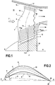
- the invention applies to any blower of an aircraft turbojet engine, and in particular to small diameter turbojet fan blowers such as that illustrated in FIG. figure 1 .
- FIG. 1 there is shown a blower 2 of a turbojet comprising a plurality of blades 4 according to the invention which are regularly spaced apart from each other about the longitudinal axis XX of the turbojet engine, this axis XX being oriented in the flow direction F of the air flow through the fan.
- Blades 4 of the blower are preferably made of a metal alloy.
- Each blade 4 comprises a blade 6 and a foot 8 mounted on a disk (or hub) 10 driven in rotation about the longitudinal axis XX of the turbojet engine.
- Each blade may also include a platform 12 which forms part of the inner wall delimiting inside the flow path 14 of the air flow F through the fan.
- a wall 16 of a casing surrounding the fan forms the outer wall which delimits outside the same flow vein.
- a radial axis ZZ is defined as being perpendicular to the longitudinal axis XX and passing through the center of gravity of the section resulting from the intersection of the blade with the inner wall. of the flow vein of the cold air flow.
- a tangential Y-Y axis forms a direct orthonormal trihedron with the X-X and Z-Z axes.
- the blade 6 of the blade 4 has a plurality of blade sections S whose centers of gravity are stacked along a line of the centers of gravity L g .
- the blade sections S are located at increasing radial distances from the longitudinal axis XX and are delimited along the radial axis ZZ between a foot section S foot and a head section S head at the top 17 of the blade .
- the foot section S foot is located at 0% of the total radial height of the blade measured from the foot of the blade to its top.
- the head section S head is located at 100% of the total radial height of the blade measured from the foot of the blade to its top.
- the resulting stack forms an aerodynamic surface that extends along the longitudinal axis XX between a leading edge 18 and a trailing edge 20 and along the tangential axis YY between a lower face 22 and an extrados face 24. ( figure 2 ).
- the figure 2 illustrates a blade section profile S which is arched in accordance with the invention with respect to a prior art (i.e. not arched) blade section profile S '.
- the accentuated camber of a blade section is defined by the presence of an inflection point I on the skeleton curve of the blade section in question (we also speak of an "S" skeleton curve).
- all blade sections between the foot section S foot and the blade section S 30 have skeleton curves having a point of inflection.
- skeleton curve of a blade section is meant here the variations, for a given blade section, of the skeletal angle ⁇ as a function of the position along the dovetail rope D (i.e. along the line segment connecting the leading edge 18 to the trailing edge 20 of the corresponding blade section).
- the skeletal angle ⁇ is formed between the tangent T at each point P of the skeleton 26 of the blade and the longitudinal axis XX of the turbojet engine (the skeleton 26 of the blade being the geometric line of the points situated at an equal distance side faces intrados 22 and extrados 24 of the blade).
- the figure 3 represents a skeleton curve C 0 for the foot section (that is to say the blade section located at 0% of the total radial height of the blade) of a blade according to the invention as a function of a percentage of the rope of the dawn (0% of the rope corresponding to the leading edge and 100% at its trailing edge).
- a skeleton curve C ' 0 for the foot section of a blade of the prior art that is to say, the profile of the foot sections is not arched.
- the skeleton curve C 0 does indeed have an inflection point I 0 (that is, a point where the tangent t 0 to the curve crosses the curve).
- the skeleton curve C ' 0 for the root section of a blade of the prior art has no point of inflection.
- the points of inflection I of all the skeleton curves of the blade sections situated between the foot section S foot and the section of blade S 30 , and in particular the point of inflection I 0 are positioned between 25% and 75% of the dawn rope length measured from the leading edge to the trailing edge.
- these inflection points are positioned between 40% and 50% of the rope length of the blade. So, on the example of the figure 3 , the point of inflection I 0 for the foot section is about 40% of the length of the rope.
- the slope of the tangent to the point of inflection of the skeleton curve decreases. continuously between the foot section S foot and the blade section S 30 located at 30% of the total radial height of the blade.
- the inventors have found that, remarkably, the presence of a curved profile at all the blade sections situated between the foot section S foot and a section of blade S 30 makes it possible to increase the mode 1F of the dawn without degrading the aerodynamic flow thereof.
- the figure 4 illustrates such an advantage.
Description
La présente invention se rapporte au domaine général des aubes de soufflante pour turboréacteur d'avion et concerne plus particulièrement le profil des sections de pied de telles aubes.The present invention relates to the general field of fan blades for an aircraft turbojet and more particularly relates to the profile of the foot sections of such blades.
Les développements apportés aux turboréacteurs d'avion visent principalement à obtenir des gains en termes de performance et de masse. Plus précisément, dans le cadre de turboréacteurs de petits diamètres, il est connu que des gains en masse peuvent être obtenus au niveau de leur soufflante en réduisant le nombre d'aubes de celle-ci, en augmentant le pas relatif en tête des aubes, et en diminuant le rapport de moyeu de la soufflante.The developments made to jet engines are mainly aimed at achieving gains in terms of performance and mass. More specifically, in the context of turbojet engines of small diameters, it is known that gains in mass can be obtained at their blower by reducing the number of blades thereof, by increasing the relative pitch at the top of the blades, and decreasing the hub ratio of the blower.
En particulier, un faible rapport de moyeu permet d'augmenter le débit spécifique du moteur (à même diamètre de soufflante), et donc sa poussée sans pour autant pénaliser la masse. Toutefois, la diminution du rapport de moyeu conduit à abaisser le premier mode de flexion des aubes de la soufflante (appelé mode 1F). Or, la coïncidence du mode 1F et du premier harmonique du moteur engendre un comportement vibratoire instable des aubes pouvant entraîner leur fissuration.In particular, a low hub ratio makes it possible to increase the specific flow rate of the engine (at the same fan diameter), and therefore its thrust without penalizing the mass. However, the reduction of the hub ratio leads to lowering the first mode of flexion of the blades of the blower (called mode 1F). However, the coincidence of the 1F mode and the first harmonic of the engine generates an unstable vibratory behavior of the blades that can lead to their cracking.
Pour résoudre ce problème de l'abaissement du mode 1F des aubes, il est possible d'augmenter, soit leur corde (c'est-à-dire la longueur du segment de droite reliant le bord d'attaque au bord de fuite des aubes), soit l'épaisseur de leur section de pied.To solve this problem of lowering the 1F blade mode, it is possible to increase either their string (ie the length of the line segment connecting the leading edge to the trailing edge of the blades ), the thickness of their foot section.
Toutefois, aucune de ces solutions n'apparaît satisfaisante. L'augmentation de la corde des aubes conduit en particulier à augmenter la longueur et la masse du turboréacteur. De même, l'épaississement des sections de pied des aubes conduit à augmenter significativement la masse de la soufflante, et donc celle du turboréacteur. Cette solution présente également comme inconvénients de pénaliser les performances du turboréacteur et d'engendrer un risque de blocage en pied de soufflante.
Il existe donc un besoin de pouvoir disposer d'une géométrie d'aube de soufflante permettant d'obtenir un abaissement de son premier mode de flexion sans pour autant augmenter la masse et la longueur du turboréacteur.There is therefore a need to have a fan blade geometry to obtain a lowering of its first bending mode without increasing the mass and length of the turbojet engine.
Ce but est atteint grâce à une aube de soufflante pour turboréacteur d'avion, comprenant une pale s'étendant axialement entre un bord d'attaque et un bord de fuite et comprenant une pluralité de sections de pale empilées radialement entre une section de pied et une section de tête, et dans laquelle, conformément à l'invention, toutes les sections de pale comprises entre la section de pied et une section de pale située à une hauteur radiale correspondant à 30% de la hauteur radiale totale de la pale possèdent une courbe de squelette ayant un point d'inflexion.This object is achieved by means of a fan blade for an aircraft turbojet, comprising a blade extending axially between a leading edge and a trailing edge and comprising a plurality of blade sections stacked radially between a foot section and a head section, and in which, in accordance with the invention, all the blade sections between the foot section and a blade section located at a radial height corresponding to 30% of the total radial height of the blade have a skeleton curve having a point of inflection.
La courbe de squelette d'une section de pale est constituée par les variations de l'angle de squelette en fonction de la position le long de la corde de l'aube. Plus précisément, par angle de squelette, on entend l'angle formé entre la tangente à chaque point du squelette de l'aube avec l'axe moteur.The skeleton curve of a blade section is made up of the variations of the skeletal angle as a function of the position along the dawn rope. More precisely, by skeleton angle, is meant the angle formed between the tangent at each point of the skeleton of the blade with the motor axis.
Les inventeurs ont constaté que, de manière remarquable, la présence d'un point d'inflexion au niveau des courbes squelette pour toutes les sections de pale situées entre 0% et 30% de la hauteur radiale totale de la pale permet d'augmenter le mode 1F de l'aube sans pour autant dégrader les performances aérodynamiques de l'aube. De plus, ce raidissement de la pale de l'aube s'effectue sans avoir à augmenter la corde de l'aube ou l'épaisseur de sa section de pied.The inventors have found that, remarkably, the presence of an inflection point at the skeleton curves for all blade sections located between 0% and 30% of the total radial height of the blade makes it possible to increase the 1F mode of dawn without degrading the aerodynamic performance of dawn. In addition, this stiffening of the blade of the dawn is done without having to increase the rope of the dawn or the thickness of its foot section.
De préférence, les points d'inflexion des courbes de squelette des sections de pale comprises entre la section de pied et une section de pale située à une hauteur radiale correspondant à 30% de la hauteur radiale totale de la pale sont situés entre 25% et 75% de la longueur de corde de l'aube mesurée depuis le bord d'attaque vers le bord de fuite.Preferably, the inflection points of the skeleton curves of the blade sections between the foot section and a blade section situated at a radial height corresponding to 30% of the total radial height of the blade are situated between 25% and 75% of the length of dawn rope measured from the leading edge to the trailing edge.
De préférence également, ces points d'inflexion sont situés entre 40% et 50% de la longueur de corde de l'aube mesurée depuis le bord d'attaque vers le bord de fuite.Also preferably, these inflection points are between 40% and 50% of the length of rope of the blade measured from the leading edge to the trailing edge.
De préférence encore, la pente de la tangente au point d'inflexion de la courbe de squelette diminue continument entre la section de pied et la section pale située à une hauteur radiale correspondant à 30% de la hauteur radiale totale de la pale.More preferably, the slope of the tangent to the inflection point of the skeleton curve decreases continuously between the foot section and the blade section located at a radial height corresponding to 30% of the total radial height of the blade.
L'invention concerne aussi une soufflante de turboréacteur d'avion comprenant une pluralité d'aubes telles que définies précédemment. Elle concerne encore un turboréacteur d'avion ayant une telle soufflante.The invention also relates to an aircraft turbojet engine fan comprising a plurality of vanes as defined above. It also relates to an aircraft turbojet having such a fan.
D'autres caractéristiques et avantages de la présente invention ressortiront de la description faite ci-dessous, en référence aux dessins annexés qui en illustrent un exemple de réalisation dépourvu de tout caractère limitatif. Sur les figures :
- la
figure 1 est une vue partielle et en coupe longitudinale d'une soufflante de turboréacteur munie d'aubes selon l'invention ; - la
figure 2 est une vue d'une section de pale d'une aube conforme à l'invention ; - la
figure 3 montre un exemple de courbe de squelette de sections de pale d'une aube conforme à l'invention ; et - la
figure 4 illustre les impacts sur l'écoulement aérodynamique d'un profil d'aube selon l'invention.
- the
figure 1 is a partial view in longitudinal section of a turbojet fan provided with blades according to the invention; - the
figure 2 is a view of a blade section of a blade according to the invention; - the
figure 3 shows an example of skeleton curve blade sections of a blade according to the invention; and - the
figure 4 illustrates the impacts on the aerodynamic flow of a blade profile according to the invention.
L'invention s'applique à toute soufflante d'un turboréacteur d'avion, et notamment aux soufflantes de turboréacteurs à petits diamètres telles que celle illustrée sur la
Sur cette
Les aubes 4 de la soufflante sont de préférence réalisées dans un alliage métallique. Chaque aube 4 comprend une pale 6 et un pied 8 monté sur un disque (ou moyeu) 10 entraîné en rotation autour de l'axe longitudinal X-X du turboréacteur. Chaque aube peut comprendre également une plateforme 12 qui forme en partie la paroi interne délimitant à l'intérieur la veine d'écoulement 14 du flux d'air F traversant la soufflante. Une paroi 16 d'un carter entourant la soufflante forme la paroi externe qui délimite à l'extérieur cette même veine d'écoulement.Blades 4 of the blower are preferably made of a metal alloy. Each blade 4 comprises a
Pour la suite de la description, pour chaque aube 4, on définit un axe radial Z-Z comme étant perpendiculaire à l'axe longitudinal X-X et passant par le centre de gravité de la coupe résultant de l'intersection de l'aube avec la paroi interne de la veine d'écoulement du flux d'air froid. Un axe tangentiel Y-Y forme un trièdre orthonormé direct avec les axes X-X et Z-Z.For the following description, for each blade 4, a radial axis ZZ is defined as being perpendicular to the longitudinal axis XX and passing through the center of gravity of the section resulting from the intersection of the blade with the inner wall. of the flow vein of the cold air flow. A tangential Y-Y axis forms a direct orthonormal trihedron with the X-X and Z-Z axes.
Comme représenté sur la
Les sections de pale S sont situées à des distances radiales croissantes de l'axe longitudinal X-X et sont délimitées selon l'axe radial Z-Z entre une section de pied Spied et une section de tête Stête au niveau du sommet 17 de l'aube. La section de pied Spied est située à 0% de la hauteur radiale totale de la pale mesurée depuis le pied de l'aube vers son sommet. De même, la section de tête Stête est située à 100% de la hauteur radiale totale de la pale mesurée depuis le pied de l'aube vers son sommet.The blade sections S are located at increasing radial distances from the longitudinal axis XX and are delimited along the radial axis ZZ between a foot section S foot and a head section S head at the
L'empilement qui en résulte forme une surface aérodynamique qui s'étend selon l'axe longitudinal X-X entre un bord d'attaque 18 et un bord de fuite 20 et selon l'axe tangentiel Y-Y entre une face intrados 22 et une face extrados 24 (
Conformément à l'invention, il est prévu de donner un profil cambré à toutes les sections de pale situées entre la section de pied Spied et une section de pale S30 située à 30% de la hauteur radiale totale de la pale mesurée depuis le pied de l'aube vers son sommet.According to the invention, provision is made to give a curved profile to all the blade sections situated between the foot section S foot and a section of blade S 30 located at 30% of the total radial height of the blade measured since the foot from dawn to its summit.
La
La cambrure accentuée d'une section de pale se définit par la présence d'un point d'inflexion I sur la courbe de squelette de la section de pale en question (on parle également de courbe squelette « en S »). Selon l'invention, toutes les sections de pale situées entre la section de pied Spied et la section de pale S30 présentent des courbes de squelette ayant un point d'inflexion.The accentuated camber of a blade section is defined by the presence of an inflection point I on the skeleton curve of the blade section in question (we also speak of an "S" skeleton curve). According to the invention, all blade sections between the foot section S foot and the blade section S 30 have skeleton curves having a point of inflection.
Par « courbe de squelette d'une section de pale », on entend ici les variations, pour une section de pale donnée, de l'angle de squelette a en fonction de la position le long de la corde D de l'aube (c'est-à-dire le long du segment de droite reliant le bord d'attaque 18 au bord de fuite 20 de la section de pale correspondante).By "skeleton curve of a blade section" is meant here the variations, for a given blade section, of the skeletal angle α as a function of the position along the dovetail rope D (i.e. along the line segment connecting the leading
Comme représenté sur la
Les variations de cet angle de squelette le long de la corde D de l'aube forment ainsi une courbe appelée courbe de squelette. Les
Ainsi, la
Sur cette
De façon avantageuse, les points d'inflexion I de toutes les courbes de squelette des sections de pale situées entre la section de pied Spied et la section de pale S30, et en particulier le point d'inflexion I0, sont positionnés entre 25% et 75% de la longueur de corde de l'aube mesurée depuis le bord d'attaque vers le bord de fuite.Advantageously, the points of inflection I of all the skeleton curves of the blade sections situated between the foot section S foot and the section of blade S 30 , and in particular the point of inflection I 0 , are positioned between 25% and 75% of the dawn rope length measured from the leading edge to the trailing edge.
De préférence, ces points d'inflexion sont positionnés entre 40% et 50% de la longueur de corde de l'aube. Ainsi, sur l'exemple de la
Par ailleurs, selon une autre disposition avantageuse, la pente de la tangente au point d'inflexion de la courbe de squelette diminue continument entre la section de pied Spied et la section pale S30 située à 30% de la hauteur radiale totale de la pale.Moreover, according to another advantageous arrangement, the slope of the tangent to the point of inflection of the skeleton curve decreases. continuously between the foot section S foot and the blade section S 30 located at 30% of the total radial height of the blade.
Cette diminution de la pente de la tangente au point d'inflexion de la courbe de squelette est continue et ininterrompue entre la section de pied Spied et la section de pale S30. Au-delà la section de pale S30, les courbes de squelette des sections de pale reprennent une allure classique, c'est-à-dire qu'elles ne présentent plus de point d'inflexion dans la zone indiquée.This decrease in the slope of the tangent to the inflection point of the skeleton curve is continuous and uninterrupted between the foot section S foot and the section of blade S 30 . Beyond the blade section S 30 , the skeleton curves of the blade sections take a conventional look, that is to say that they no longer have a point of inflection in the indicated area.
Les inventeurs ont constaté que, de manière remarquable, la présence d'un profil cambré au niveau de toutes les sections de pale situées entre la section de pied Spied et une section de pale S30 permet d'augmenter le mode 1F de l'aube sans pour autant dégrader l'écoulement aérodynamique de celle-ci.The inventors have found that, remarkably, the presence of a curved profile at all the blade sections situated between the foot section S foot and a section of blade S 30 makes it possible to increase the mode 1F of the dawn without degrading the aerodynamic flow thereof.
La
L'analyse de ces courbes représentatives de l'écoulement aérodynamique de ces aubes montre que le Mach isentropique extrados (courbe Mextra) est acceptable. En particulier, son niveau est équivalent à celui d'une aube selon l'art antérieur (courbe M'extra).The analysis of these curves representative of the aerodynamic flow of these vanes shows that the extrados isentropic Mach (M curve extra ) is acceptable. In particular, its level is equivalent to that of a blade according to the prior art (curve M ' extra ).
Claims (7)
- A fan blade (4) for an airplane turbojet, the blade comprising an airfoil (6) extending axially between a leading edge (18) and a trailing edge (20) and having a plurality of airfoil sections (S) stacked radially between a root section (Sroot) and a tip section (Stip), the blade being characterized in that all of the airfoil sections situated between the root section (Sroot) and an airfoil section (S30) situated at a radial height corresponding to 30% of the total radial height of the airfoil possess a skeleton curve having a point of inflection, the skeleton curve for a given airfoil section comprising the variations in the skeleton angle as a function of position along the chord of the blade.
- A blade according to claim 1, wherein the points of inflection of the skeleton curves of airfoil sections lying between the root section and an airfoil section situated at a radial height corresponding to 30% of the total radial height of the airfoil are situated in the range 25% to 75% of the chord length of the blade as measured from the leading edge going towards the trailing edge.
- A blade according to claim 2, wherein the points of inflection of the skeleton curves of airfoil sections lying between the root section and an airfoil section situated at a radial height corresponding to 30% of the total radial height of the airfoil are situated in the range 40% to 50% of the chord length of the blade as measured from the leading edge going towards the trailing edge.
- A blade according to any one of claims 1 to 3, wherein the slope of the tangent at the point of inflection of the skeleton curve decreases continuously between the root section and the airfoil section situated at a radial height corresponding to 30% of the total radial height of the airfoil.
- A blade according to any one of claims 1 to 4, wherein the airfoil is made of metal.
- An airplane turbojet fan (2) including a plurality of blades (4) according to any one of claims 1 to 5.
- An airplane turbojet including a fan (2) according to claim 6.
Applications Claiming Priority (2)
| Application Number | Priority Date | Filing Date | Title |
|---|---|---|---|
| FR1255020A FR2991373B1 (en) | 2012-05-31 | 2012-05-31 | BLOWER DAWN FOR AIRBORNE AIRCRAFT WITH CAMBRE PROFILE IN FOOT SECTIONS |
| PCT/FR2013/051125 WO2013178914A1 (en) | 2012-05-31 | 2013-05-23 | Fan blade for a turbojet of an aircraft having a cambered profile in the foot sections |
Publications (2)
| Publication Number | Publication Date |
|---|---|
| EP2855847A1 EP2855847A1 (en) | 2015-04-08 |
| EP2855847B1 true EP2855847B1 (en) | 2018-07-18 |
Family
ID=46889193
Family Applications (1)
| Application Number | Title | Priority Date | Filing Date |
|---|---|---|---|
| EP13728469.1A Active EP2855847B1 (en) | 2012-05-31 | 2013-05-23 | Fan blade for a turbojet of an aircraft having a cambered profile in the foot sections |
Country Status (8)
| Country | Link |
|---|---|
| US (1) | US11333164B2 (en) |
| EP (1) | EP2855847B1 (en) |
| CN (1) | CN104364473B (en) |
| BR (1) | BR112014029523B1 (en) |
| CA (1) | CA2873942C (en) |
| FR (1) | FR2991373B1 (en) |
| RU (1) | RU2639462C2 (en) |
| WO (1) | WO2013178914A1 (en) |
Families Citing this family (12)
| Publication number | Priority date | Publication date | Assignee | Title |
|---|---|---|---|---|
| FR3032494B1 (en) * | 2015-02-06 | 2018-05-25 | Safran Aircraft Engines | AUBE DE SOUFFLANTE |
| EP3088663A1 (en) * | 2015-04-28 | 2016-11-02 | Siemens Aktiengesellschaft | Method for profiling a blade |
| FR3038341B1 (en) * | 2015-07-03 | 2017-07-28 | Snecma | METHOD OF ALTERATION OF THE LAYING ACT OF THE AERODYNAMIC SURFACE OF A GAS TURBINE ENGINE BLOWER BLADE |
| RU167312U1 (en) * | 2016-03-24 | 2017-01-10 | Федеральное государственное унитарное предприятие "Центральный институт авиационного моторостроения им. П.И. Баранова" | Impeller blade for high speed axial compressor |
| EP3239460A1 (en) * | 2016-04-27 | 2017-11-01 | Siemens Aktiengesellschaft | Method for profiling blades of an axial turbo machine |
| GB201704657D0 (en) * | 2017-03-24 | 2017-05-10 | Rolls Royce Plc | Gas turbine engine |
| CN108252953B (en) * | 2018-03-15 | 2023-08-29 | 上海优睿农牧科技有限公司 | Fan blade and method |
| LU100758B1 (en) * | 2018-04-03 | 2019-10-07 | Carpyz Sas | Method of Design, Construction and Manufacture of Turbocharger, Helicopter, Reactor (THR) Wheel |
| CN109057869A (en) * | 2018-07-12 | 2018-12-21 | 上海理工大学 | Inclined teeth trailing edge blade |
| FR3087828B1 (en) * | 2018-10-26 | 2021-01-08 | Safran Helicopter Engines | MOBILE TURBOMACHINE BLADE |
| GB201819413D0 (en) * | 2018-11-29 | 2019-01-16 | Rolls Royce Plc | Geared turbofan engine |
| FR3089553B1 (en) * | 2018-12-11 | 2021-01-22 | Safran Aircraft Engines | TURBOMACHINE DAWN AT ARROW LAW WITH HIGH MARGIN AT FLOTATION |
Family Cites Families (23)
| Publication number | Priority date | Publication date | Assignee | Title |
|---|---|---|---|---|
| SU521401A1 (en) * | 1971-10-01 | 1976-07-15 | Рижский Краснознаменный Институт Инженеров Гражданской Авиации Имени Ленинского Комсомола | Axial compressor blade |
| GB2106192A (en) * | 1981-09-24 | 1983-04-07 | Rolls Royce | Turbomachine blade |
| JP2665005B2 (en) * | 1989-10-24 | 1997-10-22 | 三菱重工業株式会社 | Blades of axial flow machines |
| US5088894A (en) * | 1990-05-02 | 1992-02-18 | Westinghouse Electric Corp. | Turbomachine blade fastening |
| US5642985A (en) * | 1995-11-17 | 1997-07-01 | United Technologies Corporation | Swept turbomachinery blade |
| US6071077A (en) * | 1996-04-09 | 2000-06-06 | Rolls-Royce Plc | Swept fan blade |
| FR2851798B1 (en) | 2003-02-27 | 2005-04-29 | Snecma Moteurs | TURBOREACTOR TURBINE BOW |
| GB2400089B (en) * | 2003-04-04 | 2006-07-26 | Adrian Alexander Hubbard | High lift and high strength aerofoil section |
| US7204676B2 (en) * | 2004-05-14 | 2007-04-17 | Pratt & Whitney Canada Corp. | Fan blade curvature distribution for high core pressure ratio fan |
| US7476086B2 (en) * | 2005-04-07 | 2009-01-13 | General Electric Company | Tip cambered swept blade |
| DE102005042115A1 (en) * | 2005-09-05 | 2007-03-08 | Rolls-Royce Deutschland Ltd & Co Kg | Blade of a fluid flow machine with block-defined profile skeleton line |
| CN101326342B (en) * | 2005-10-11 | 2012-06-13 | 阿尔斯通技术有限公司 | Turbo-machine blade |
| FR2900194A1 (en) * | 2006-04-20 | 2007-10-26 | Snecma Sa | AERODYNAMIC PROFILE FOR A TURBINE BLADE |
| JP4664890B2 (en) * | 2006-11-02 | 2011-04-06 | 三菱重工業株式会社 | Transonic blades and axial flow rotating machines |
| DE102006055869A1 (en) * | 2006-11-23 | 2008-05-29 | Rolls-Royce Deutschland Ltd & Co Kg | Rotor and guide blades designing method for turbo-machine i.e. gas turbine engine, involves running skeleton curve in profile section in sectional line angle distribution area lying between upper and lower limit curves |
| DE102008004014A1 (en) * | 2008-01-11 | 2009-07-23 | Continental Automotive Gmbh | Guide vane for a variable turbine geometry |
| FR2928174B1 (en) * | 2008-02-28 | 2011-05-06 | Snecma | DAWN WITH NON AXISYMETRIC PLATFORM: HOLLOW AND BOSS ON EXTRADOS. |
| EP2299124A1 (en) * | 2009-09-04 | 2011-03-23 | Siemens Aktiengesellschaft | Rotor blade for an axial compressor |
| US8393872B2 (en) * | 2009-10-23 | 2013-03-12 | General Electric Company | Turbine airfoil |
| GB201003084D0 (en) * | 2010-02-24 | 2010-04-14 | Rolls Royce Plc | An aerofoil |
| DE102010014556B4 (en) * | 2010-04-10 | 2013-01-03 | Mtu Aero Engines Gmbh | Guide vane of a compressor |
| FR2971539B1 (en) * | 2011-02-10 | 2013-03-08 | Snecma | PLATFORM BLADE ASSEMBLY FOR SUBSONIC FLOW |
| JP6133748B2 (en) * | 2013-10-09 | 2017-05-24 | 三菱重工業株式会社 | Impeller and rotating machine having the same |
-
2012
- 2012-05-31 FR FR1255020A patent/FR2991373B1/en active Active
-
2013
- 2013-05-23 CN CN201380028788.0A patent/CN104364473B/en active Active
- 2013-05-23 CA CA2873942A patent/CA2873942C/en active Active
- 2013-05-23 RU RU2014152258A patent/RU2639462C2/en active
- 2013-05-23 WO PCT/FR2013/051125 patent/WO2013178914A1/en active Application Filing
- 2013-05-23 BR BR112014029523-9A patent/BR112014029523B1/en active IP Right Grant
- 2013-05-23 US US14/403,003 patent/US11333164B2/en active Active
- 2013-05-23 EP EP13728469.1A patent/EP2855847B1/en active Active
Non-Patent Citations (1)
| Title |
|---|
| None * |
Also Published As
| Publication number | Publication date |
|---|---|
| CA2873942A1 (en) | 2013-12-05 |
| BR112014029523A8 (en) | 2021-08-31 |
| BR112014029523A2 (en) | 2017-06-27 |
| WO2013178914A1 (en) | 2013-12-05 |
| RU2639462C2 (en) | 2017-12-21 |
| FR2991373A1 (en) | 2013-12-06 |
| FR2991373B1 (en) | 2014-06-20 |
| US11333164B2 (en) | 2022-05-17 |
| CN104364473A (en) | 2015-02-18 |
| EP2855847A1 (en) | 2015-04-08 |
| CN104364473B (en) | 2017-05-03 |
| RU2014152258A (en) | 2016-07-20 |
| US20150152880A1 (en) | 2015-06-04 |
| BR112014029523B1 (en) | 2022-01-11 |
| CA2873942C (en) | 2020-05-12 |
Similar Documents
| Publication | Publication Date | Title |
|---|---|---|
| EP2855847B1 (en) | Fan blade for a turbojet of an aircraft having a cambered profile in the foot sections | |
| EP2809883B1 (en) | Jet engine fan blade | |
| EP1921324B1 (en) | Turbomachine arrow blade | |
| CA2975570C (en) | Guide assembly with optimised aerodynamic performance | |
| EP3676480B1 (en) | Turbomachine fan flow-straightener vane, turbomachine assembly comprising such a vane, and turbomachine equipped with said vane or with said assembly | |
| EP3033530B1 (en) | Turbomachine stator vane | |
| EP1693572A2 (en) | Bleeding air from the tip of the rotating blades in a high pressure compressor of a turbine engine | |
| EP1452741B1 (en) | Curved blade for gas turbine engine | |
| FR3081185A1 (en) | STATOR ELEMENT OF TURBOMACHINE | |
| EP3253970B1 (en) | Fan blade | |
| EP2976507B1 (en) | Blade and blade dihedral angle | |
| CA2801222A1 (en) | Aerodynamic coupling between two annular rows of stationary vanes in a turbine engine | |
| FR3065497B1 (en) | AIR EJECTION CHANNEL TOWARDING THE TOP AND TILT DOWN OF A TURBOMACHINE BLADE | |
| BE1028097B1 (en) | Turbomachine compressor blade, compressor and turbomachine fitted therewith | |
| EP3344879B1 (en) | Design of the trailing edge skeleton angle of struts crossing the secondary flow of a turbomachine with bypass flow | |
| FR3045709A1 (en) | AUBE DE SOUFFLANTE | |
| FR3049013A1 (en) | DAWN OF RECTIFIER | |
| FR3100287A1 (en) | Improved turbofan engine | |
| FR3136448A1 (en) | Non-ducted thrust production assembly including a rectifier loaded at the blade root | |
| FR3135758A1 (en) | Retention casing of a fan having a truncated spherical part | |
| FR3138835A1 (en) | TURBOMACHINE INCLUDING VARIABLE PITCH VANES | |
| BE1028234A1 (en) | BLADE FOR TURBOMACHINE COMPRESSOR | |
| FR3074847A1 (en) | BLOWER MODULE | |
| FR3010747A1 (en) | AUTOMOBILE FAN WITH OPTIMIZED BLADES FOR ACOUSTICS AND AERODYNAMICS |
Legal Events
| Date | Code | Title | Description |
|---|---|---|---|
| PUAI | Public reference made under article 153(3) epc to a published international application that has entered the european phase |
Free format text: ORIGINAL CODE: 0009012 |
|
| 17P | Request for examination filed |
Effective date: 20141118 |
|
| AK | Designated contracting states |
Kind code of ref document: A1 Designated state(s): AL AT BE BG CH CY CZ DE DK EE ES FI FR GB GR HR HU IE IS IT LI LT LU LV MC MK MT NL NO PL PT RO RS SE SI SK SM TR |
|
| AX | Request for extension of the european patent |
Extension state: BA ME |
|
| DAX | Request for extension of the european patent (deleted) | ||
| STAA | Information on the status of an ep patent application or granted ep patent |
Free format text: STATUS: EXAMINATION IS IN PROGRESS |
|
| 17Q | First examination report despatched |
Effective date: 20170724 |
|
| GRAP | Despatch of communication of intention to grant a patent |
Free format text: ORIGINAL CODE: EPIDOSNIGR1 |
|
| STAA | Information on the status of an ep patent application or granted ep patent |
Free format text: STATUS: GRANT OF PATENT IS INTENDED |
|
| INTG | Intention to grant announced |
Effective date: 20180223 |
|
| GRAS | Grant fee paid |
Free format text: ORIGINAL CODE: EPIDOSNIGR3 |
|
| GRAA | (expected) grant |
Free format text: ORIGINAL CODE: 0009210 |
|
| STAA | Information on the status of an ep patent application or granted ep patent |
Free format text: STATUS: THE PATENT HAS BEEN GRANTED |
|
| RAP1 | Party data changed (applicant data changed or rights of an application transferred) |
Owner name: SAFRAN AIRCRAFT ENGINES |
|
| AK | Designated contracting states |
Kind code of ref document: B1 Designated state(s): AL AT BE BG CH CY CZ DE DK EE ES FI FR GB GR HR HU IE IS IT LI LT LU LV MC MK MT NL NO PL PT RO RS SE SI SK SM TR |
|
| REG | Reference to a national code |
Ref country code: GB Ref legal event code: FG4D Free format text: NOT ENGLISH |
|
| REG | Reference to a national code |
Ref country code: CH Ref legal event code: EP |
|
| REG | Reference to a national code |
Ref country code: IE Ref legal event code: FG4D Free format text: LANGUAGE OF EP DOCUMENT: FRENCH |
|
| REG | Reference to a national code |
Ref country code: DE Ref legal event code: R096 Ref document number: 602013040451 Country of ref document: DE |
|
| REG | Reference to a national code |
Ref country code: AT Ref legal event code: REF Ref document number: 1019581 Country of ref document: AT Kind code of ref document: T Effective date: 20180815 |
|
| REG | Reference to a national code |
Ref country code: SE Ref legal event code: TRGR |
|
| REG | Reference to a national code |
Ref country code: NL Ref legal event code: MP Effective date: 20180718 |
|
| REG | Reference to a national code |
Ref country code: LT Ref legal event code: MG4D |
|
| REG | Reference to a national code |
Ref country code: AT Ref legal event code: MK05 Ref document number: 1019581 Country of ref document: AT Kind code of ref document: T Effective date: 20180718 |
|
| PG25 | Lapsed in a contracting state [announced via postgrant information from national office to epo] |
Ref country code: NL Free format text: LAPSE BECAUSE OF FAILURE TO SUBMIT A TRANSLATION OF THE DESCRIPTION OR TO PAY THE FEE WITHIN THE PRESCRIBED TIME-LIMIT Effective date: 20180718 |
|
| PG25 | Lapsed in a contracting state [announced via postgrant information from national office to epo] |
Ref country code: LT Free format text: LAPSE BECAUSE OF FAILURE TO SUBMIT A TRANSLATION OF THE DESCRIPTION OR TO PAY THE FEE WITHIN THE PRESCRIBED TIME-LIMIT Effective date: 20180718 Ref country code: BG Free format text: LAPSE BECAUSE OF FAILURE TO SUBMIT A TRANSLATION OF THE DESCRIPTION OR TO PAY THE FEE WITHIN THE PRESCRIBED TIME-LIMIT Effective date: 20181018 Ref country code: GR Free format text: LAPSE BECAUSE OF FAILURE TO SUBMIT A TRANSLATION OF THE DESCRIPTION OR TO PAY THE FEE WITHIN THE PRESCRIBED TIME-LIMIT Effective date: 20181019 Ref country code: IS Free format text: LAPSE BECAUSE OF FAILURE TO SUBMIT A TRANSLATION OF THE DESCRIPTION OR TO PAY THE FEE WITHIN THE PRESCRIBED TIME-LIMIT Effective date: 20181118 Ref country code: NO Free format text: LAPSE BECAUSE OF FAILURE TO SUBMIT A TRANSLATION OF THE DESCRIPTION OR TO PAY THE FEE WITHIN THE PRESCRIBED TIME-LIMIT Effective date: 20181018 Ref country code: PL Free format text: LAPSE BECAUSE OF FAILURE TO SUBMIT A TRANSLATION OF THE DESCRIPTION OR TO PAY THE FEE WITHIN THE PRESCRIBED TIME-LIMIT Effective date: 20180718 Ref country code: AT Free format text: LAPSE BECAUSE OF FAILURE TO SUBMIT A TRANSLATION OF THE DESCRIPTION OR TO PAY THE FEE WITHIN THE PRESCRIBED TIME-LIMIT Effective date: 20180718 Ref country code: FI Free format text: LAPSE BECAUSE OF FAILURE TO SUBMIT A TRANSLATION OF THE DESCRIPTION OR TO PAY THE FEE WITHIN THE PRESCRIBED TIME-LIMIT Effective date: 20180718 Ref country code: RS Free format text: LAPSE BECAUSE OF FAILURE TO SUBMIT A TRANSLATION OF THE DESCRIPTION OR TO PAY THE FEE WITHIN THE PRESCRIBED TIME-LIMIT Effective date: 20180718 |
|
| PG25 | Lapsed in a contracting state [announced via postgrant information from national office to epo] |
Ref country code: LV Free format text: LAPSE BECAUSE OF FAILURE TO SUBMIT A TRANSLATION OF THE DESCRIPTION OR TO PAY THE FEE WITHIN THE PRESCRIBED TIME-LIMIT Effective date: 20180718 Ref country code: AL Free format text: LAPSE BECAUSE OF FAILURE TO SUBMIT A TRANSLATION OF THE DESCRIPTION OR TO PAY THE FEE WITHIN THE PRESCRIBED TIME-LIMIT Effective date: 20180718 Ref country code: HR Free format text: LAPSE BECAUSE OF FAILURE TO SUBMIT A TRANSLATION OF THE DESCRIPTION OR TO PAY THE FEE WITHIN THE PRESCRIBED TIME-LIMIT Effective date: 20180718 |
|
| REG | Reference to a national code |
Ref country code: DE Ref legal event code: R097 Ref document number: 602013040451 Country of ref document: DE |
|
| PG25 | Lapsed in a contracting state [announced via postgrant information from national office to epo] |
Ref country code: RO Free format text: LAPSE BECAUSE OF FAILURE TO SUBMIT A TRANSLATION OF THE DESCRIPTION OR TO PAY THE FEE WITHIN THE PRESCRIBED TIME-LIMIT Effective date: 20180718 Ref country code: EE Free format text: LAPSE BECAUSE OF FAILURE TO SUBMIT A TRANSLATION OF THE DESCRIPTION OR TO PAY THE FEE WITHIN THE PRESCRIBED TIME-LIMIT Effective date: 20180718 Ref country code: CZ Free format text: LAPSE BECAUSE OF FAILURE TO SUBMIT A TRANSLATION OF THE DESCRIPTION OR TO PAY THE FEE WITHIN THE PRESCRIBED TIME-LIMIT Effective date: 20180718 Ref country code: ES Free format text: LAPSE BECAUSE OF FAILURE TO SUBMIT A TRANSLATION OF THE DESCRIPTION OR TO PAY THE FEE WITHIN THE PRESCRIBED TIME-LIMIT Effective date: 20180718 |
|
| PLBE | No opposition filed within time limit |
Free format text: ORIGINAL CODE: 0009261 |
|
| STAA | Information on the status of an ep patent application or granted ep patent |
Free format text: STATUS: NO OPPOSITION FILED WITHIN TIME LIMIT |
|
| PG25 | Lapsed in a contracting state [announced via postgrant information from national office to epo] |
Ref country code: DK Free format text: LAPSE BECAUSE OF FAILURE TO SUBMIT A TRANSLATION OF THE DESCRIPTION OR TO PAY THE FEE WITHIN THE PRESCRIBED TIME-LIMIT Effective date: 20180718 Ref country code: SM Free format text: LAPSE BECAUSE OF FAILURE TO SUBMIT A TRANSLATION OF THE DESCRIPTION OR TO PAY THE FEE WITHIN THE PRESCRIBED TIME-LIMIT Effective date: 20180718 Ref country code: SK Free format text: LAPSE BECAUSE OF FAILURE TO SUBMIT A TRANSLATION OF THE DESCRIPTION OR TO PAY THE FEE WITHIN THE PRESCRIBED TIME-LIMIT Effective date: 20180718 |
|
| 26N | No opposition filed |
Effective date: 20190423 |
|
| PG25 | Lapsed in a contracting state [announced via postgrant information from national office to epo] |
Ref country code: SI Free format text: LAPSE BECAUSE OF FAILURE TO SUBMIT A TRANSLATION OF THE DESCRIPTION OR TO PAY THE FEE WITHIN THE PRESCRIBED TIME-LIMIT Effective date: 20180718 |
|
| REG | Reference to a national code |
Ref country code: CH Ref legal event code: PL |
|
| PG25 | Lapsed in a contracting state [announced via postgrant information from national office to epo] |
Ref country code: CH Free format text: LAPSE BECAUSE OF NON-PAYMENT OF DUE FEES Effective date: 20190531 Ref country code: MC Free format text: LAPSE BECAUSE OF FAILURE TO SUBMIT A TRANSLATION OF THE DESCRIPTION OR TO PAY THE FEE WITHIN THE PRESCRIBED TIME-LIMIT Effective date: 20180718 Ref country code: LI Free format text: LAPSE BECAUSE OF NON-PAYMENT OF DUE FEES Effective date: 20190531 |
|
| REG | Reference to a national code |
Ref country code: BE Ref legal event code: MM Effective date: 20190531 |
|
| PG25 | Lapsed in a contracting state [announced via postgrant information from national office to epo] |
Ref country code: LU Free format text: LAPSE BECAUSE OF NON-PAYMENT OF DUE FEES Effective date: 20190523 |
|
| PG25 | Lapsed in a contracting state [announced via postgrant information from national office to epo] |
Ref country code: TR Free format text: LAPSE BECAUSE OF FAILURE TO SUBMIT A TRANSLATION OF THE DESCRIPTION OR TO PAY THE FEE WITHIN THE PRESCRIBED TIME-LIMIT Effective date: 20180718 |
|
| PG25 | Lapsed in a contracting state [announced via postgrant information from national office to epo] |
Ref country code: IE Free format text: LAPSE BECAUSE OF NON-PAYMENT OF DUE FEES Effective date: 20190523 |
|
| PG25 | Lapsed in a contracting state [announced via postgrant information from national office to epo] |
Ref country code: BE Free format text: LAPSE BECAUSE OF NON-PAYMENT OF DUE FEES Effective date: 20190531 |
|
| PG25 | Lapsed in a contracting state [announced via postgrant information from national office to epo] |
Ref country code: PT Free format text: LAPSE BECAUSE OF FAILURE TO SUBMIT A TRANSLATION OF THE DESCRIPTION OR TO PAY THE FEE WITHIN THE PRESCRIBED TIME-LIMIT Effective date: 20181118 |
|
| PG25 | Lapsed in a contracting state [announced via postgrant information from national office to epo] |
Ref country code: CY Free format text: LAPSE BECAUSE OF FAILURE TO SUBMIT A TRANSLATION OF THE DESCRIPTION OR TO PAY THE FEE WITHIN THE PRESCRIBED TIME-LIMIT Effective date: 20180718 |
|
| PG25 | Lapsed in a contracting state [announced via postgrant information from national office to epo] |
Ref country code: HU Free format text: LAPSE BECAUSE OF FAILURE TO SUBMIT A TRANSLATION OF THE DESCRIPTION OR TO PAY THE FEE WITHIN THE PRESCRIBED TIME-LIMIT; INVALID AB INITIO Effective date: 20130523 Ref country code: MT Free format text: LAPSE BECAUSE OF FAILURE TO SUBMIT A TRANSLATION OF THE DESCRIPTION OR TO PAY THE FEE WITHIN THE PRESCRIBED TIME-LIMIT Effective date: 20180718 |
|
| PG25 | Lapsed in a contracting state [announced via postgrant information from national office to epo] |
Ref country code: MK Free format text: LAPSE BECAUSE OF FAILURE TO SUBMIT A TRANSLATION OF THE DESCRIPTION OR TO PAY THE FEE WITHIN THE PRESCRIBED TIME-LIMIT Effective date: 20180718 |
|
| PGFP | Annual fee paid to national office [announced via postgrant information from national office to epo] |
Ref country code: IT Payment date: 20230420 Year of fee payment: 11 Ref country code: FR Payment date: 20230420 Year of fee payment: 11 Ref country code: DE Payment date: 20230419 Year of fee payment: 11 |
|
| PGFP | Annual fee paid to national office [announced via postgrant information from national office to epo] |
Ref country code: SE Payment date: 20230419 Year of fee payment: 11 |
|
| PGFP | Annual fee paid to national office [announced via postgrant information from national office to epo] |
Ref country code: GB Payment date: 20230420 Year of fee payment: 11 |