EP2855627B1 - Bimesogenic compounds and mesogenic media - Google Patents
Bimesogenic compounds and mesogenic media Download PDFInfo
- Publication number
- EP2855627B1 EP2855627B1 EP13727515.2A EP13727515A EP2855627B1 EP 2855627 B1 EP2855627 B1 EP 2855627B1 EP 13727515 A EP13727515 A EP 13727515A EP 2855627 B1 EP2855627 B1 EP 2855627B1
- Authority
- EP
- European Patent Office
- Prior art keywords
- phe
- phel
- cyc
- independently
- groups
- Prior art date
- Legal status (The legal status is an assumption and is not a legal conclusion. Google has not performed a legal analysis and makes no representation as to the accuracy of the status listed.)
- Not-in-force
Links
- 150000001875 compounds Chemical class 0.000 title claims description 142
- 239000004973 liquid crystal related substance Substances 0.000 claims description 55
- -1 piperidine-1,4-diyl Chemical group 0.000 claims description 46
- 229910052731 fluorine Inorganic materials 0.000 claims description 44
- 125000004432 carbon atom Chemical group C* 0.000 claims description 41
- 229910052801 chlorine Inorganic materials 0.000 claims description 31
- 125000000217 alkyl group Chemical group 0.000 claims description 22
- 239000007788 liquid Substances 0.000 claims description 22
- 125000006850 spacer group Chemical group 0.000 claims description 16
- 229910052736 halogen Inorganic materials 0.000 claims description 14
- 125000003545 alkoxy group Chemical group 0.000 claims description 13
- 229910052739 hydrogen Inorganic materials 0.000 claims description 11
- 229910052757 nitrogen Inorganic materials 0.000 claims description 11
- 125000001140 1,4-phenylene group Chemical group [H]C1=C([H])C([*:2])=C([H])C([H])=C1[*:1] 0.000 claims description 9
- 125000004430 oxygen atom Chemical group O* 0.000 claims description 8
- 125000001153 fluoro group Chemical group F* 0.000 claims description 7
- 125000001309 chloro group Chemical group Cl* 0.000 claims description 6
- 125000005647 linker group Chemical group 0.000 claims description 6
- 230000036961 partial effect Effects 0.000 claims description 4
- 125000004435 hydrogen atom Chemical group [H]* 0.000 claims description 3
- 229910052717 sulfur Inorganic materials 0.000 claims description 3
- 125000005407 trans-1,4-cyclohexylene group Chemical group [H]C1([H])C([H])([H])[C@]([H])([*:2])C([H])([H])C([H])([H])[C@@]1([H])[*:1] 0.000 claims description 3
- 125000004453 alkoxycarbonyl group Chemical group 0.000 claims description 2
- 125000004448 alkyl carbonyl group Chemical group 0.000 claims description 2
- 229910052760 oxygen Inorganic materials 0.000 claims description 2
- 125000005843 halogen group Chemical group 0.000 claims 2
- 239000000203 mixture Substances 0.000 description 103
- YMWUJEATGCHHMB-UHFFFAOYSA-N Dichloromethane Chemical compound ClCCl YMWUJEATGCHHMB-UHFFFAOYSA-N 0.000 description 93
- RTZKZFJDLAIYFH-UHFFFAOYSA-N Diethyl ether Chemical compound CCOCC RTZKZFJDLAIYFH-UHFFFAOYSA-N 0.000 description 61
- 239000012071 phase Substances 0.000 description 40
- 239000000463 material Substances 0.000 description 34
- WEVYAHXRMPXWCK-UHFFFAOYSA-N Acetonitrile Chemical compound CC#N WEVYAHXRMPXWCK-UHFFFAOYSA-N 0.000 description 28
- 239000011541 reaction mixture Substances 0.000 description 28
- 239000000758 substrate Substances 0.000 description 28
- VYPSYNLAJGMNEJ-UHFFFAOYSA-N Silicium dioxide Chemical compound O=[Si]=O VYPSYNLAJGMNEJ-UHFFFAOYSA-N 0.000 description 27
- 238000006243 chemical reaction Methods 0.000 description 25
- BWHMMNNQKKPAPP-UHFFFAOYSA-L potassium carbonate Chemical compound [K+].[K+].[O-]C([O-])=O BWHMMNNQKKPAPP-UHFFFAOYSA-L 0.000 description 24
- ZWEHNKRNPOVVGH-UHFFFAOYSA-N 2-Butanone Chemical compound CCC(C)=O ZWEHNKRNPOVVGH-UHFFFAOYSA-N 0.000 description 22
- WYURNTSHIVDZCO-UHFFFAOYSA-N Tetrahydrofuran Chemical compound C1CCOC1 WYURNTSHIVDZCO-UHFFFAOYSA-N 0.000 description 22
- 239000007787 solid Substances 0.000 description 22
- 239000000243 solution Substances 0.000 description 22
- 210000004027 cell Anatomy 0.000 description 21
- 239000000047 product Substances 0.000 description 21
- 230000005684 electric field Effects 0.000 description 18
- 230000003287 optical effect Effects 0.000 description 18
- ZMANZCXQSJIPKH-UHFFFAOYSA-N Triethylamine Chemical compound CCN(CC)CC ZMANZCXQSJIPKH-UHFFFAOYSA-N 0.000 description 17
- IJGRMHOSHXDMSA-UHFFFAOYSA-N Atomic nitrogen Chemical compound N#N IJGRMHOSHXDMSA-UHFFFAOYSA-N 0.000 description 16
- KDLHZDBZIXYQEI-UHFFFAOYSA-N palladium Substances [Pd] KDLHZDBZIXYQEI-UHFFFAOYSA-N 0.000 description 16
- XLYOFNOQVPJJNP-UHFFFAOYSA-N water Substances O XLYOFNOQVPJJNP-UHFFFAOYSA-N 0.000 description 15
- 125000000956 methoxy group Chemical group [H]C([H])([H])O* 0.000 description 14
- 125000000876 trifluoromethoxy group Chemical group FC(F)(F)O* 0.000 description 14
- 239000000377 silicon dioxide Substances 0.000 description 13
- 230000015572 biosynthetic process Effects 0.000 description 12
- 230000003098 cholesteric effect Effects 0.000 description 12
- 229910000027 potassium carbonate Inorganic materials 0.000 description 12
- 238000010992 reflux Methods 0.000 description 12
- 238000003786 synthesis reaction Methods 0.000 description 12
- RIOQSEWOXXDEQQ-UHFFFAOYSA-N triphenylphosphine Chemical compound C1=CC=CC=C1P(C=1C=CC=CC=1)C1=CC=CC=C1 RIOQSEWOXXDEQQ-UHFFFAOYSA-N 0.000 description 12
- 125000002947 alkylene group Chemical group 0.000 description 11
- PMZURENOXWZQFD-UHFFFAOYSA-L Sodium Sulfate Chemical compound [Na+].[Na+].[O-]S([O-])(=O)=O PMZURENOXWZQFD-UHFFFAOYSA-L 0.000 description 10
- 125000002496 methyl group Chemical group [H]C([H])([H])* 0.000 description 10
- 238000000819 phase cycle Methods 0.000 description 10
- YLQBMQCUIZJEEH-UHFFFAOYSA-N tetrahydrofuran Natural products C=1C=COC=1 YLQBMQCUIZJEEH-UHFFFAOYSA-N 0.000 description 9
- CSCPPACGZOOCGX-UHFFFAOYSA-N Acetone Chemical compound CC(C)=O CSCPPACGZOOCGX-UHFFFAOYSA-N 0.000 description 8
- 238000000034 method Methods 0.000 description 8
- 238000003756 stirring Methods 0.000 description 8
- 125000002023 trifluoromethyl group Chemical group FC(F)(F)* 0.000 description 8
- 239000004986 Cholesteric liquid crystals (ChLC) Substances 0.000 description 7
- 239000000654 additive Substances 0.000 description 7
- 230000000052 comparative effect Effects 0.000 description 7
- 239000012043 crude product Substances 0.000 description 7
- 239000000706 filtrate Substances 0.000 description 7
- 239000003208 petroleum Substances 0.000 description 7
- 230000007704 transition Effects 0.000 description 7
- 0 C*(c(c(F)cc(-c(c(F)c1)ccc1OC(*C(Oc(cc1)cc(F)c1-c1cc(F)c(*)c(F)c1)=O)=O)c1)c1F)=C Chemical compound C*(c(c(F)cc(-c(c(F)c1)ccc1OC(*C(Oc(cc1)cc(F)c1-c1cc(F)c(*)c(F)c1)=O)=O)c1)c1F)=C 0.000 description 6
- ZMXDDKWLCZADIW-UHFFFAOYSA-N N,N-Dimethylformamide Chemical compound CN(C)C=O ZMXDDKWLCZADIW-UHFFFAOYSA-N 0.000 description 6
- KWYUFKZDYYNOTN-UHFFFAOYSA-M Potassium hydroxide Chemical compound [OH-].[K+] KWYUFKZDYYNOTN-UHFFFAOYSA-M 0.000 description 6
- CDBYLPFSWZWCQE-UHFFFAOYSA-L Sodium Carbonate Chemical compound [Na+].[Na+].[O-]C([O-])=O CDBYLPFSWZWCQE-UHFFFAOYSA-L 0.000 description 6
- YXFVVABEGXRONW-UHFFFAOYSA-N Toluene Chemical compound CC1=CC=CC=C1 YXFVVABEGXRONW-UHFFFAOYSA-N 0.000 description 6
- 125000004786 difluoromethoxy group Chemical group [H]C(F)(F)O* 0.000 description 6
- UAOMVDZJSHZZME-UHFFFAOYSA-N diisopropylamine Chemical compound CC(C)NC(C)C UAOMVDZJSHZZME-UHFFFAOYSA-N 0.000 description 6
- 239000002019 doping agent Substances 0.000 description 6
- 150000002367 halogens Chemical group 0.000 description 6
- MZRVEZGGRBJDDB-UHFFFAOYSA-N n-Butyllithium Substances [Li]CCCC MZRVEZGGRBJDDB-UHFFFAOYSA-N 0.000 description 6
- 239000002244 precipitate Substances 0.000 description 6
- 238000000746 purification Methods 0.000 description 6
- 230000002829 reductive effect Effects 0.000 description 6
- 230000004044 response Effects 0.000 description 6
- 239000002904 solvent Substances 0.000 description 6
- 239000003054 catalyst Substances 0.000 description 5
- 210000002421 cell wall Anatomy 0.000 description 5
- 239000004744 fabric Substances 0.000 description 5
- 239000011521 glass Substances 0.000 description 5
- 238000005984 hydrogenation reaction Methods 0.000 description 5
- 238000001953 recrystallisation Methods 0.000 description 5
- 229910052938 sodium sulfate Inorganic materials 0.000 description 5
- 235000011152 sodium sulphate Nutrition 0.000 description 5
- VHYFNPMBLIVWCW-UHFFFAOYSA-N 4-Dimethylaminopyridine Chemical compound CN(C)C1=CC=NC=C1 VHYFNPMBLIVWCW-UHFFFAOYSA-N 0.000 description 4
- LFQSCWFLJHTTHZ-UHFFFAOYSA-N Ethanol Chemical compound CCO LFQSCWFLJHTTHZ-UHFFFAOYSA-N 0.000 description 4
- CPELXLSAUQHCOX-UHFFFAOYSA-N Hydrogen bromide Chemical compound Br CPELXLSAUQHCOX-UHFFFAOYSA-N 0.000 description 4
- YNAVUWVOSKDBBP-UHFFFAOYSA-N Morpholine Chemical compound C1COCCN1 YNAVUWVOSKDBBP-UHFFFAOYSA-N 0.000 description 4
- JCXJVPUVTGWSNB-UHFFFAOYSA-N Nitrogen dioxide Chemical compound O=[N]=O JCXJVPUVTGWSNB-UHFFFAOYSA-N 0.000 description 4
- 239000004642 Polyimide Substances 0.000 description 4
- 239000004990 Smectic liquid crystal Substances 0.000 description 4
- VSCWAEJMTAWNJL-UHFFFAOYSA-K aluminium trichloride Chemical compound Cl[Al](Cl)Cl VSCWAEJMTAWNJL-UHFFFAOYSA-K 0.000 description 4
- 238000004587 chromatography analysis Methods 0.000 description 4
- 230000000694 effects Effects 0.000 description 4
- QUPDWYMUPZLYJZ-UHFFFAOYSA-N ethyl Chemical compound C[CH2] QUPDWYMUPZLYJZ-UHFFFAOYSA-N 0.000 description 4
- 239000011368 organic material Substances 0.000 description 4
- 229920001721 polyimide Polymers 0.000 description 4
- NLKNQRATVPKPDG-UHFFFAOYSA-M potassium iodide Substances [K+].[I-] NLKNQRATVPKPDG-UHFFFAOYSA-M 0.000 description 4
- UMLFTCYAQPPZER-UHFFFAOYSA-N 4-(bromomethyl)benzonitrile Chemical compound BrCC1=CC=C(C#N)C=C1 UMLFTCYAQPPZER-UHFFFAOYSA-N 0.000 description 3
- 229910021595 Copper(I) iodide Inorganic materials 0.000 description 3
- QOSSAOTZNIDXMA-UHFFFAOYSA-N Dicylcohexylcarbodiimide Chemical compound C1CCCCC1N=C=NC1CCCCC1 QOSSAOTZNIDXMA-UHFFFAOYSA-N 0.000 description 3
- VEXZGXHMUGYJMC-UHFFFAOYSA-N Hydrochloric acid Chemical compound Cl VEXZGXHMUGYJMC-UHFFFAOYSA-N 0.000 description 3
- MHAJPDPJQMAIIY-UHFFFAOYSA-N Hydrogen peroxide Chemical compound OO MHAJPDPJQMAIIY-UHFFFAOYSA-N 0.000 description 3
- 239000004988 Nematic liquid crystal Substances 0.000 description 3
- MUBZPKHOEPUJKR-UHFFFAOYSA-N Oxalic acid Chemical compound OC(=O)C(O)=O MUBZPKHOEPUJKR-UHFFFAOYSA-N 0.000 description 3
- HEMHJVSKTPXQMS-UHFFFAOYSA-M Sodium hydroxide Chemical compound [OH-].[Na+] HEMHJVSKTPXQMS-UHFFFAOYSA-M 0.000 description 3
- 125000002252 acyl group Chemical group 0.000 description 3
- 230000005540 biological transmission Effects 0.000 description 3
- 229910052799 carbon Inorganic materials 0.000 description 3
- 230000008859 change Effects 0.000 description 3
- 239000013058 crude material Substances 0.000 description 3
- 239000013078 crystal Substances 0.000 description 3
- 230000007935 neutral effect Effects 0.000 description 3
- DMOVPHYFYSASTC-UHFFFAOYSA-N nona-1,8-diyne Chemical compound C#CCCCCCC#C DMOVPHYFYSASTC-UHFFFAOYSA-N 0.000 description 3
- 125000005004 perfluoroethyl group Chemical group FC(F)(F)C(F)(F)* 0.000 description 3
- 238000002360 preparation method Methods 0.000 description 3
- 238000010008 shearing Methods 0.000 description 3
- 229910000029 sodium carbonate Inorganic materials 0.000 description 3
- 239000000126 substance Substances 0.000 description 3
- ITMCEJHCFYSIIV-UHFFFAOYSA-N triflic acid Chemical compound OS(=O)(=O)C(F)(F)F ITMCEJHCFYSIIV-UHFFFAOYSA-N 0.000 description 3
- FSTKSTMFMLANPA-UHFFFAOYSA-N 1,1-dibromononane Chemical compound CCCCCCCCC(Br)Br FSTKSTMFMLANPA-UHFFFAOYSA-N 0.000 description 2
- NVNPLEPBDPJYRZ-UHFFFAOYSA-N 1-(bromomethyl)-4-fluorobenzene Chemical compound FC1=CC=C(CBr)C=C1 NVNPLEPBDPJYRZ-UHFFFAOYSA-N 0.000 description 2
- 125000004200 2-methoxyethyl group Chemical group [H]C([H])([H])OC([H])([H])C([H])([H])* 0.000 description 2
- RYVOZMPTISNBDB-UHFFFAOYSA-N 4-bromo-2-fluorophenol Chemical compound OC1=CC=C(Br)C=C1F RYVOZMPTISNBDB-UHFFFAOYSA-N 0.000 description 2
- CVNOWLNNPYYEOH-UHFFFAOYSA-N 4-cyanophenol Chemical compound OC1=CC=C(C#N)C=C1 CVNOWLNNPYYEOH-UHFFFAOYSA-N 0.000 description 2
- 229960000549 4-dimethylaminophenol Drugs 0.000 description 2
- ZEYHEAKUIGZSGI-UHFFFAOYSA-N 4-methoxybenzoic acid Chemical compound COC1=CC=C(C(O)=O)C=C1 ZEYHEAKUIGZSGI-UHFFFAOYSA-N 0.000 description 2
- NLXLAEXVIDQMFP-UHFFFAOYSA-N Ammonia chloride Chemical compound [NH4+].[Cl-] NLXLAEXVIDQMFP-UHFFFAOYSA-N 0.000 description 2
- CPELXLSAUQHCOX-UHFFFAOYSA-M Bromide Chemical compound [Br-] CPELXLSAUQHCOX-UHFFFAOYSA-M 0.000 description 2
- WKBOTKDWSSQWDR-UHFFFAOYSA-N Bromine atom Chemical compound [Br] WKBOTKDWSSQWDR-UHFFFAOYSA-N 0.000 description 2
- QMMFVYPAHWMCMS-UHFFFAOYSA-N Dimethyl sulfide Chemical compound CSC QMMFVYPAHWMCMS-UHFFFAOYSA-N 0.000 description 2
- SNRUBQQJIBEYMU-UHFFFAOYSA-N Dodecane Natural products CCCCCCCCCCCC SNRUBQQJIBEYMU-UHFFFAOYSA-N 0.000 description 2
- KRHYYFGTRYWZRS-UHFFFAOYSA-M Fluoride anion Chemical compound [F-] KRHYYFGTRYWZRS-UHFFFAOYSA-M 0.000 description 2
- CSNNHWWHGAXBCP-UHFFFAOYSA-L Magnesium sulfate Chemical compound [Mg+2].[O-][S+2]([O-])([O-])[O-] CSNNHWWHGAXBCP-UHFFFAOYSA-L 0.000 description 2
- PVZMXULSHARAJG-UHFFFAOYSA-N N,N-diethylethanamine molecular hydrogen Chemical compound [H][H].CCN(CC)CC PVZMXULSHARAJG-UHFFFAOYSA-N 0.000 description 2
- IMNFDUFMRHMDMM-UHFFFAOYSA-N N-Heptane Chemical compound CCCCCCC IMNFDUFMRHMDMM-UHFFFAOYSA-N 0.000 description 2
- FAPWRFPIFSIZLT-UHFFFAOYSA-M Sodium chloride Chemical compound [Na+].[Cl-] FAPWRFPIFSIZLT-UHFFFAOYSA-M 0.000 description 2
- 238000010521 absorption reaction Methods 0.000 description 2
- 239000008346 aqueous phase Substances 0.000 description 2
- 239000007864 aqueous solution Substances 0.000 description 2
- 125000004429 atom Chemical group 0.000 description 2
- AGEZXYOZHKGVCM-UHFFFAOYSA-N benzyl bromide Chemical compound BrCC1=CC=CC=C1 AGEZXYOZHKGVCM-UHFFFAOYSA-N 0.000 description 2
- YNHIGQDRGKUECZ-UHFFFAOYSA-L bis(triphenylphosphine)palladium(ii) dichloride Chemical compound [Cl-].[Cl-].[Pd+2].C1=CC=CC=C1P(C=1C=CC=CC=1)C1=CC=CC=C1.C1=CC=CC=C1P(C=1C=CC=CC=1)C1=CC=CC=C1 YNHIGQDRGKUECZ-UHFFFAOYSA-L 0.000 description 2
- GDTBXPJZTBHREO-UHFFFAOYSA-N bromine Substances BrBr GDTBXPJZTBHREO-UHFFFAOYSA-N 0.000 description 2
- 229910052794 bromium Inorganic materials 0.000 description 2
- 125000000484 butyl group Chemical group [H]C([*])([H])C([H])([H])C([H])([H])C([H])([H])[H] 0.000 description 2
- 239000003795 chemical substances by application Substances 0.000 description 2
- 239000000470 constituent Substances 0.000 description 2
- 238000001816 cooling Methods 0.000 description 2
- 210000002858 crystal cell Anatomy 0.000 description 2
- 125000001651 cyanato group Chemical group [*]OC#N 0.000 description 2
- JHAYEQICABJSTP-UHFFFAOYSA-N decoquinate Chemical group N1C=C(C(=O)OCC)C(=O)C2=C1C=C(OCC)C(OCCCCCCCCCC)=C2 JHAYEQICABJSTP-UHFFFAOYSA-N 0.000 description 2
- 125000002704 decyl group Chemical group [H]C([H])([H])C([H])([H])C([H])([H])C([H])([H])C([H])([H])C([H])([H])C([H])([H])C([H])([H])C([H])([H])C([H])([H])* 0.000 description 2
- 229940043279 diisopropylamine Drugs 0.000 description 2
- 125000003438 dodecyl group Chemical group [H]C([H])([H])C([H])([H])C([H])([H])C([H])([H])C([H])([H])C([H])([H])C([H])([H])C([H])([H])C([H])([H])C([H])([H])C([H])([H])C([H])([H])* 0.000 description 2
- 239000003480 eluent Substances 0.000 description 2
- 125000005745 ethoxymethyl group Chemical group [H]C([H])([H])C([H])([H])OC([H])([H])* 0.000 description 2
- 125000001495 ethyl group Chemical group [H]C([H])([H])C([H])([H])* 0.000 description 2
- 239000005262 ferroelectric liquid crystals (FLCs) Substances 0.000 description 2
- 238000001914 filtration Methods 0.000 description 2
- 238000003818 flash chromatography Methods 0.000 description 2
- 238000010438 heat treatment Methods 0.000 description 2
- 125000003187 heptyl group Chemical group [H]C([*])([H])C([H])([H])C([H])([H])C([H])([H])C([H])([H])C([H])([H])C([H])([H])[H] 0.000 description 2
- 125000004051 hexyl group Chemical group [H]C([H])([H])C([H])([H])C([H])([H])C([H])([H])C([H])([H])C([H])([H])* 0.000 description 2
- 229910000042 hydrogen bromide Inorganic materials 0.000 description 2
- 239000013067 intermediate product Substances 0.000 description 2
- 125000001972 isopentyl group Chemical group [H]C([H])([H])C([H])(C([H])([H])[H])C([H])([H])C([H])([H])* 0.000 description 2
- DLEDOFVPSDKWEF-UHFFFAOYSA-N lithium butane Chemical compound [Li+].CCC[CH2-] DLEDOFVPSDKWEF-UHFFFAOYSA-N 0.000 description 2
- 238000002844 melting Methods 0.000 description 2
- 230000008018 melting Effects 0.000 description 2
- 125000004184 methoxymethyl group Chemical group [H]C([H])([H])OC([H])([H])* 0.000 description 2
- 238000012986 modification Methods 0.000 description 2
- 230000004048 modification Effects 0.000 description 2
- 125000001421 myristyl group Chemical group [H]C([*])([H])C([H])([H])C([H])([H])C([H])([H])C([H])([H])C([H])([H])C([H])([H])C([H])([H])C([H])([H])C([H])([H])C([H])([H])C([H])([H])C([H])([H])C([H])([H])[H] 0.000 description 2
- 239000012299 nitrogen atmosphere Substances 0.000 description 2
- 125000001400 nonyl group Chemical group [H]C([*])([H])C([H])([H])C([H])([H])C([H])([H])C([H])([H])C([H])([H])C([H])([H])C([H])([H])C([H])([H])[H] 0.000 description 2
- 125000002347 octyl group Chemical group [H]C([*])([H])C([H])([H])C([H])([H])C([H])([H])C([H])([H])C([H])([H])C([H])([H])C([H])([H])[H] 0.000 description 2
- 239000012074 organic phase Substances 0.000 description 2
- 125000002958 pentadecyl group Chemical group [H]C([*])([H])C([H])([H])C([H])([H])C([H])([H])C([H])([H])C([H])([H])C([H])([H])C([H])([H])C([H])([H])C([H])([H])C([H])([H])C([H])([H])C([H])([H])C([H])([H])C([H])([H])[H] 0.000 description 2
- 125000001147 pentyl group Chemical group C(CCCC)* 0.000 description 2
- 239000004033 plastic Substances 0.000 description 2
- 239000002985 plastic film Substances 0.000 description 2
- 229920006255 plastic film Polymers 0.000 description 2
- BASFCYQUMIYNBI-UHFFFAOYSA-N platinum Chemical compound [Pt] BASFCYQUMIYNBI-UHFFFAOYSA-N 0.000 description 2
- 229920000642 polymer Polymers 0.000 description 2
- 239000000843 powder Substances 0.000 description 2
- 230000008569 process Effects 0.000 description 2
- NCNISYUOWMIOPI-UHFFFAOYSA-N propane-1,1-dithiol Chemical compound CCC(S)S NCNISYUOWMIOPI-UHFFFAOYSA-N 0.000 description 2
- 125000001436 propyl group Chemical group [H]C([*])([H])C([H])([H])C([H])([H])[H] 0.000 description 2
- 238000010926 purge Methods 0.000 description 2
- 230000009467 reduction Effects 0.000 description 2
- 239000010802 sludge Substances 0.000 description 2
- GEHJYWRUCIMESM-UHFFFAOYSA-L sodium sulfite Chemical compound [Na+].[Na+].[O-]S([O-])=O GEHJYWRUCIMESM-UHFFFAOYSA-L 0.000 description 2
- 239000012265 solid product Substances 0.000 description 2
- 239000012258 stirred mixture Substances 0.000 description 2
- 238000003860 storage Methods 0.000 description 2
- 238000004381 surface treatment Methods 0.000 description 2
- ZMZDMBWJUHKJPS-UHFFFAOYSA-N thiocyanic acid Chemical compound SC#N ZMZDMBWJUHKJPS-UHFFFAOYSA-N 0.000 description 2
- 125000002889 tridecyl group Chemical group [H]C([*])([H])C([H])([H])C([H])([H])C([H])([H])C([H])([H])C([H])([H])C([H])([H])C([H])([H])C([H])([H])C([H])([H])C([H])([H])C([H])([H])C([H])([H])[H] 0.000 description 2
- QAEDZJGFFMLHHQ-UHFFFAOYSA-N trifluoroacetic anhydride Chemical compound FC(F)(F)C(=O)OC(=O)C(F)(F)F QAEDZJGFFMLHHQ-UHFFFAOYSA-N 0.000 description 2
- 125000002948 undecyl group Chemical group [H]C([*])([H])C([H])([H])C([H])([H])C([H])([H])C([H])([H])C([H])([H])C([H])([H])C([H])([H])C([H])([H])C([H])([H])C([H])([H])[H] 0.000 description 2
- 238000010792 warming Methods 0.000 description 2
- 125000004955 1,4-cyclohexylene group Chemical group [H]C1([H])C([H])([H])C([H])([*:1])C([H])([H])C([H])([H])C1([H])[*:2] 0.000 description 1
- OIRHKGBNGGSCGS-UHFFFAOYSA-N 1-bromo-2-iodobenzene Chemical compound BrC1=CC=CC=C1I OIRHKGBNGGSCGS-UHFFFAOYSA-N 0.000 description 1
- UUFQTNFCRMXOAE-UHFFFAOYSA-N 1-methylmethylene Chemical compound C[CH] UUFQTNFCRMXOAE-UHFFFAOYSA-N 0.000 description 1
- MHMRKNHYHPORRR-UHFFFAOYSA-N 2-bromo-1-fluoro-3-iodobenzene Chemical compound FC1=CC=CC(I)=C1Br MHMRKNHYHPORRR-UHFFFAOYSA-N 0.000 description 1
- VMRXHUXZVZRLSS-UHFFFAOYSA-N 2-butyl-1-methyl-3-phenylbenzene Chemical group CCCCC1=C(C)C=CC=C1C1=CC=CC=C1 VMRXHUXZVZRLSS-UHFFFAOYSA-N 0.000 description 1
- YLRJKFZBCDDWHU-UHFFFAOYSA-N 3-hydroxy-2-(2-hydroxyphenyl)benzonitrile Chemical compound OC1=CC=CC=C1C1=C(O)C=CC=C1C#N YLRJKFZBCDDWHU-UHFFFAOYSA-N 0.000 description 1
- 125000001331 3-methylbutoxy group Chemical group [H]C([H])([H])C([H])(C([H])([H])[H])C([H])([H])C([H])([H])O* 0.000 description 1
- CUJZEZUKSJKTOB-UHFFFAOYSA-N CC(CCc1cc(C)c2F)Cc1c2F Chemical compound CC(CCc1cc(C)c2F)Cc1c2F CUJZEZUKSJKTOB-UHFFFAOYSA-N 0.000 description 1
- MDTCMZAFDPQTGO-UHFFFAOYSA-N CC(c(cc1)cc(F)c1C(Oc(cc1)cc(F)c1C#N)=O)c(cc1)cc(F)c1C(Oc(cc1F)ccc1C#N)=O Chemical compound CC(c(cc1)cc(F)c1C(Oc(cc1)cc(F)c1C#N)=O)c(cc1)cc(F)c1C(Oc(cc1F)ccc1C#N)=O MDTCMZAFDPQTGO-UHFFFAOYSA-N 0.000 description 1
- HOPDTPGXBZCBNP-UHFFFAOYSA-N CC1(C)OB(c(cc2)ccc2C#N)OC1(C)C Chemical compound CC1(C)OB(c(cc2)ccc2C#N)OC1(C)C HOPDTPGXBZCBNP-UHFFFAOYSA-N 0.000 description 1
- 101100167062 Caenorhabditis elegans chch-3 gene Proteins 0.000 description 1
- DYSJQUQJVBYIOT-UHFFFAOYSA-N Cc(ccc(C)c1F)c1F Chemical compound Cc(ccc(C)c1F)c1F DYSJQUQJVBYIOT-UHFFFAOYSA-N 0.000 description 1
- JWPLONMBQSEIOG-UHFFFAOYSA-N Cc1c(Cc(cc2)c(C)cc2-c(cc2)ccc2C#N)ccc(-c(cc2)ccc2C#N)c1 Chemical compound Cc1c(Cc(cc2)c(C)cc2-c(cc2)ccc2C#N)ccc(-c(cc2)ccc2C#N)c1 JWPLONMBQSEIOG-UHFFFAOYSA-N 0.000 description 1
- RHOOLJLEYYXKTK-UHFFFAOYSA-N Cc1cnc(C)nc1 Chemical compound Cc1cnc(C)nc1 RHOOLJLEYYXKTK-UHFFFAOYSA-N 0.000 description 1
- ZRMIETZFPZGBEB-UHFFFAOYSA-N N#Cc(cc1)ccc1-c(cc1)ccc1O Chemical compound N#Cc(cc1)ccc1-c(cc1)ccc1O ZRMIETZFPZGBEB-UHFFFAOYSA-N 0.000 description 1
- MWLMSLRDUMQMGC-UHFFFAOYSA-N N#Cc(cc1)ccc1OC(c(ccc(CC(CC=C1C(Oc(cc2)ccc2C#N)(F)F)C=C1F)c1)c1F)(F)F Chemical compound N#Cc(cc1)ccc1OC(c(ccc(CC(CC=C1C(Oc(cc2)ccc2C#N)(F)F)C=C1F)c1)c1F)(F)F MWLMSLRDUMQMGC-UHFFFAOYSA-N 0.000 description 1
- XCLGCZJDTIVCRA-UHFFFAOYSA-N N#Cc(cc1)ccc1OC(c1ccc(Cc(cc2)ccc2C(Oc(cc2)ccc2C#N)=O)cc1)=O Chemical compound N#Cc(cc1)ccc1OC(c1ccc(Cc(cc2)ccc2C(Oc(cc2)ccc2C#N)=O)cc1)=O XCLGCZJDTIVCRA-UHFFFAOYSA-N 0.000 description 1
- ISWSIDIOOBJBQZ-UHFFFAOYSA-N Phenol Chemical compound OC1=CC=CC=C1 ISWSIDIOOBJBQZ-UHFFFAOYSA-N 0.000 description 1
- 239000002253 acid Substances 0.000 description 1
- 230000002378 acidificating effect Effects 0.000 description 1
- 230000000996 additive effect Effects 0.000 description 1
- 239000000853 adhesive Substances 0.000 description 1
- 230000001070 adhesive effect Effects 0.000 description 1
- 125000003342 alkenyl group Chemical group 0.000 description 1
- 125000003302 alkenyloxy group Chemical group 0.000 description 1
- 125000005672 alkyl ethenyl alkyl group Chemical group 0.000 description 1
- 125000005742 alkyl ethenyl group Chemical group 0.000 description 1
- 125000000746 allylic group Chemical group 0.000 description 1
- 235000019270 ammonium chloride Nutrition 0.000 description 1
- 238000004458 analytical method Methods 0.000 description 1
- 239000012298 atmosphere Substances 0.000 description 1
- 230000001680 brushing effect Effects 0.000 description 1
- 239000011248 coating agent Substances 0.000 description 1
- 238000000576 coating method Methods 0.000 description 1
- 238000004440 column chromatography Methods 0.000 description 1
- LSXDOTMGLUJQCM-UHFFFAOYSA-M copper(i) iodide Chemical compound I[Cu] LSXDOTMGLUJQCM-UHFFFAOYSA-M 0.000 description 1
- 239000002537 cosmetic Substances 0.000 description 1
- 238000002425 crystallisation Methods 0.000 description 1
- 230000003247 decreasing effect Effects 0.000 description 1
- 230000007547 defect Effects 0.000 description 1
- 125000001028 difluoromethyl group Chemical group [H]C(F)(F)* 0.000 description 1
- 239000000539 dimer Substances 0.000 description 1
- 238000004090 dissolution Methods 0.000 description 1
- 238000001035 drying Methods 0.000 description 1
- 239000000975 dye Substances 0.000 description 1
- 150000002148 esters Chemical class 0.000 description 1
- 150000002159 estradiols Chemical class 0.000 description 1
- 125000005670 ethenylalkyl group Chemical group 0.000 description 1
- 125000005678 ethenylene group Chemical group [H]C([*:1])=C([H])[*:2] 0.000 description 1
- DQYBDCGIPTYXML-UHFFFAOYSA-N ethoxyethane;hydrate Chemical compound O.CCOCC DQYBDCGIPTYXML-UHFFFAOYSA-N 0.000 description 1
- 125000002534 ethynyl group Chemical group [H]C#C* 0.000 description 1
- 239000000374 eutectic mixture Substances 0.000 description 1
- 230000001747 exhibiting effect Effects 0.000 description 1
- 125000004785 fluoromethoxy group Chemical group [H]C([H])(F)O* 0.000 description 1
- 125000004216 fluoromethyl group Chemical group [H]C([H])(F)* 0.000 description 1
- 230000009477 glass transition Effects 0.000 description 1
- AMGQUBHHOARCQH-UHFFFAOYSA-N indium;oxotin Chemical compound [In].[Sn]=O AMGQUBHHOARCQH-UHFFFAOYSA-N 0.000 description 1
- 230000002427 irreversible effect Effects 0.000 description 1
- 125000000959 isobutyl group Chemical group [H]C([H])([H])C([H])(C([H])([H])[H])C([H])([H])* 0.000 description 1
- 238000002955 isolation Methods 0.000 description 1
- 125000001449 isopropyl group Chemical group [H]C([H])([H])C([H])(*)C([H])([H])[H] 0.000 description 1
- 229910052943 magnesium sulfate Inorganic materials 0.000 description 1
- 235000019341 magnesium sulphate Nutrition 0.000 description 1
- PSHKMPUSSFXUIA-UHFFFAOYSA-N n,n-dimethylpyridin-2-amine Chemical compound CN(C)C1=CC=CC=N1 PSHKMPUSSFXUIA-UHFFFAOYSA-N 0.000 description 1
- 238000010899 nucleation Methods 0.000 description 1
- 230000006911 nucleation Effects 0.000 description 1
- 230000005693 optoelectronics Effects 0.000 description 1
- 235000006408 oxalic acid Nutrition 0.000 description 1
- 229910052763 palladium Inorganic materials 0.000 description 1
- 125000001997 phenyl group Chemical group [H]C1=C([H])C([H])=C(*)C([H])=C1[H] 0.000 description 1
- 125000000843 phenylene group Chemical group C1(=C(C=CC=C1)*)* 0.000 description 1
- 239000000049 pigment Substances 0.000 description 1
- 230000010287 polarization Effects 0.000 description 1
- 239000011369 resultant mixture Substances 0.000 description 1
- 230000002441 reversible effect Effects 0.000 description 1
- 230000000630 rising effect Effects 0.000 description 1
- 229920006395 saturated elastomer Polymers 0.000 description 1
- 238000012216 screening Methods 0.000 description 1
- 230000035945 sensitivity Effects 0.000 description 1
- 229910052710 silicon Inorganic materials 0.000 description 1
- 229910052814 silicon oxide Inorganic materials 0.000 description 1
- 239000011780 sodium chloride Substances 0.000 description 1
- 235000010265 sodium sulphite Nutrition 0.000 description 1
- SHNJHLWLAGUBOV-UHFFFAOYSA-N sodium;oxido(oxo)borane;octahydrate Chemical compound O.O.O.O.O.O.O.O.[Na+].[O-]B=O SHNJHLWLAGUBOV-UHFFFAOYSA-N 0.000 description 1
- 238000009987 spinning Methods 0.000 description 1
- 235000015096 spirit Nutrition 0.000 description 1
- 239000013589 supplement Substances 0.000 description 1
- 239000000725 suspension Substances 0.000 description 1
- 229920003002 synthetic resin Polymers 0.000 description 1
- 239000000057 synthetic resin Substances 0.000 description 1
- HWCKGOZZJDHMNC-UHFFFAOYSA-M tetraethylammonium bromide Chemical compound [Br-].CC[N+](CC)(CC)CC HWCKGOZZJDHMNC-UHFFFAOYSA-M 0.000 description 1
- 230000009466 transformation Effects 0.000 description 1
- 230000001131 transforming effect Effects 0.000 description 1
- 125000000391 vinyl group Chemical group [H]C([*])=C([H])[H] 0.000 description 1
Classifications
-
- C—CHEMISTRY; METALLURGY
- C09—DYES; PAINTS; POLISHES; NATURAL RESINS; ADHESIVES; COMPOSITIONS NOT OTHERWISE PROVIDED FOR; APPLICATIONS OF MATERIALS NOT OTHERWISE PROVIDED FOR
- C09K—MATERIALS FOR MISCELLANEOUS APPLICATIONS, NOT PROVIDED FOR ELSEWHERE
- C09K19/00—Liquid crystal materials
- C09K19/02—Liquid crystal materials characterised by optical, electrical or physical properties of the components, in general
- C09K19/0258—Flexoelectric
-
- C—CHEMISTRY; METALLURGY
- C09—DYES; PAINTS; POLISHES; NATURAL RESINS; ADHESIVES; COMPOSITIONS NOT OTHERWISE PROVIDED FOR; APPLICATIONS OF MATERIALS NOT OTHERWISE PROVIDED FOR
- C09K—MATERIALS FOR MISCELLANEOUS APPLICATIONS, NOT PROVIDED FOR ELSEWHERE
- C09K19/00—Liquid crystal materials
- C09K19/02—Liquid crystal materials characterised by optical, electrical or physical properties of the components, in general
- C09K19/0208—Twisted Nematic (T.N.); Super Twisted Nematic (S.T.N.); Optical Mode Interference (O.M.I.)
-
- C—CHEMISTRY; METALLURGY
- C09—DYES; PAINTS; POLISHES; NATURAL RESINS; ADHESIVES; COMPOSITIONS NOT OTHERWISE PROVIDED FOR; APPLICATIONS OF MATERIALS NOT OTHERWISE PROVIDED FOR
- C09K—MATERIALS FOR MISCELLANEOUS APPLICATIONS, NOT PROVIDED FOR ELSEWHERE
- C09K19/00—Liquid crystal materials
- C09K19/52—Liquid crystal materials characterised by components which are not liquid crystals, e.g. additives with special physical aspect: solvents, solid particles
- C09K19/58—Dopants or charge transfer agents
-
- C—CHEMISTRY; METALLURGY
- C09—DYES; PAINTS; POLISHES; NATURAL RESINS; ADHESIVES; COMPOSITIONS NOT OTHERWISE PROVIDED FOR; APPLICATIONS OF MATERIALS NOT OTHERWISE PROVIDED FOR
- C09K—MATERIALS FOR MISCELLANEOUS APPLICATIONS, NOT PROVIDED FOR ELSEWHERE
- C09K19/00—Liquid crystal materials
- C09K19/52—Liquid crystal materials characterised by components which are not liquid crystals, e.g. additives with special physical aspect: solvents, solid particles
- C09K19/58—Dopants or charge transfer agents
- C09K19/586—Optically active dopants; chiral dopants
-
- C—CHEMISTRY; METALLURGY
- C09—DYES; PAINTS; POLISHES; NATURAL RESINS; ADHESIVES; COMPOSITIONS NOT OTHERWISE PROVIDED FOR; APPLICATIONS OF MATERIALS NOT OTHERWISE PROVIDED FOR
- C09K—MATERIALS FOR MISCELLANEOUS APPLICATIONS, NOT PROVIDED FOR ELSEWHERE
- C09K19/00—Liquid crystal materials
- C09K19/04—Liquid crystal materials characterised by the chemical structure of the liquid crystal components, e.g. by a specific unit
- C09K2019/0444—Liquid crystal materials characterised by the chemical structure of the liquid crystal components, e.g. by a specific unit characterized by a linking chain between rings or ring systems, a bridging chain between extensive mesogenic moieties or an end chain group
Definitions
- the invention relates to bimesogenic compounds of formula I wherein R 11 , R 12 , MG 11 , MG 12 and Sp 1 have the meaning given herein below, to the use of bimesogenic compounds of formula I in liquid crystal media and particular to flexoelectric liquid crystal devices comprising a liquid crystal medium according to the present invention.
- LCDs Liquid Crystal Displays
- LCDs are widely used to display information. LCDs are used for direct view displays, as well as for projection type displays.
- the electro-optical mode which is employed for most displays still is the twisted nematic (TN)-mode with its various modifications. Besides this mode, the super twisted nematic (STN)-mode and more recently the optically compensated bend (OCB)-mode and the electrically controlled birefringence (ECB)-mode with their various modifications, as e. g.
- TN twisted nematic
- STN super twisted nematic
- OCB optically compensated bend
- ECB electrically controlled birefringence
- VAN vertically aligned nematic
- PVA patterned ITO vertically aligned nematic
- PSVA polymer stabilized vertically aligned nematic
- MVA multi domain vertically aligned nematic
- electro-optical modes employing an electrical field substantially parallel to the substrates, respectively the liquid crystal layer, like e.g. the In Plane Switching (short IPS) mode (as disclosed e.g.
- liquid crystal means a compound that under suitable conditions of temperature, pressure and concentration can exist as a mesophase (nematic, smectic, etc.) or in particular as a LC phase.
- mesophase nematic, smectic, etc.
- Non-amphiphilic mesogenic compounds comprise for example one or more calamitic, banana-shaped or discotic mesogenic groups.
- Flexoelectric liquid crystal materials are known in prior art and for example suggested in US 2008/142758 A1 , US 2010/296038 A1 , US 2009/115957 A1 and by Henderson et al. in Liquid crystals, 2001, 28, 3, 463 - 472 .
- the flexoelectric effect is described inter alia by Chandrasekhar, "Liquid Crystals", 2nd edition, Cambridge University Press (1992 ) and P.G. deGennes et al., "The Physics of Liquid Crystals", 2nd edition, Oxford Science Publications (1995 ).
- the cholesteric liquid crystals are oriented in the "uniformly lying helix" arrangement (ULH), which also give this display mode its name.
- UH "uniformly lying helix” arrangement
- a chiral substance which is mixed with a nematic material induces a helical twist transforming the material into a chiral nematic material, which is equivalent to a cholesteric material.
- the term "chiral” in general is used to describe an object that is non-superimposable on its mirror image.
- “Achiral" (non- chiral) objects are objects that are identical to their mirror image.
- the terms chiral nematic and cholesteric are used synonymously in this application, unless explicitly stated otherwise.
- the pitch induced by the chiral substance (Po) is in a first approximation inversely proportional to the concentration (c) of the chiral material used.
- the constant of proportionality of this relation is called the helical twisting power (HTP) of the chiral substance and defined by equation (1) HTP ⁇ 1 / c ⁇ P 0 wherein
- the uniform lying helix texture is realized using a chiral nematic liquid crystal with a short pitch, typically in the range from 0.2 ⁇ m to 1 ⁇ m, preferably of 1.0 ⁇ m or less, in particular of 0.5 ⁇ m or less, which is unidirectional aligned with its helical axis parallel to the substrates, e. g. glass plates, of a liquid crystal cell.
- the helical axis of the chiral nematic liquid crystal is equivalent to the optical axis of a birefringent plate.
- the optical axis is rotated in the plane of the cell, similar as the director of a ferroelectric liquid crystal rotate as in a surface stabilized ferroelectric liquid crystal display.
- the flexoelectric effect is characterized by fast response times typically ranging from 6 ⁇ s to 100 ⁇ s. It further features excellent grey scale capability.
- the field induces a splay bend structure in the director which is accommodated by a tilt in the optical axis.
- the angle of the rotation of the axis is in first approximation directly and linearly proportional to the strength of the electrical field.
- the optical effect is best seen when the liquid crystal cell is placed between crossed polarizers with the optical axis in the unpowered state at an angle of 22.5° to the absorption axis of one of the polarizers.
- This angle of 22.5° is also the ideal angle of rotation of the electric field, as thus, by the inversion the electrical field, the optical axis is rotated by 45° and by appropriate selection of the relative orientations of the preferred direction of the axis of the helix, the absorption axis of the polarizer and the direction of the electric field, the optical axis can be switched from parallel to one polarizer to the center angle between both polarizers. The optimum contrast is then achieved when the total angle of the switching of the optical axis is 45°. In that case the arrangement can be used as a switchable quarter wave plate, provided the optical retardation, i. e. the product of the effective birefringence of the liquid crystal and the cell gap, is selected to be the quarter of the wave length.
- the wavelength referred to is 550 nm, the wavelength for which the sensitivity of the human eye is highest, unless explicitly stated otherwise.
- This angle of rotation is half the switching angle in a flexoelectric switching element.
- a relatively new display mode may be considered as an alternative mode to succeed the IPS, as it can show improved black levels, even compared to other display mode providing wide viewing angles (e.g. IPS, VA etc.).
- USH uniformly standing helix
- bimesogenic liquid crystal materials For the USH mode, like for the ULH mode, flexoelectric switching has been proposed, using bimesogenic liquid crystal materials.
- Bimesogenic compounds are known in general from prior art ( cf. also Hori, K., limuro, M., Nakao, A., Toriumi, H., J. Mol. Struc. 2004, 699, 23-29 ).
- the term "bimesogenic compound” relates to compounds comprising two mesogenic groups in the molecule. Just like normal mesogens they can form many mesophases, depending on their structure. In particular compounds of formula I induce a second nematic phase, when added to a nematic liquid crystal medium.
- mesogenic group means in this context, a group with the ability to induce liquid crystal (LC) phase behaviour.
- the compounds comprising mesogenic groups do not necessarily have to exhibit an LC phase themselves. It is also possible that they show LC phase behaviour only in mixtures with other compounds.
- liquid crystal is used hereinafter for both mesogenic and LC materials.
- ⁇ n n e ⁇ n o
- n e the extraordinary refractive index
- n o the ordinary refractive index
- n av . 2 n o 2 + n e 2 / 3 1 / 2
- the extraordinary refractive index n e and the ordinary refractive index n o can be measured using an Abbe refractometer. ⁇ n can then be calculated from equation (5).
- the wave length of light generally referred to in this application is 550 nm, unless explicitly specified otherwise.
- the cell gap of the cells preferably is in the range from 1 ⁇ m to 20 ⁇ m, in particular within the range from 2.0 ⁇ m to 10 ⁇ m.
- the dielectric anisotropy ( ⁇ ) should be as small as possible, to prevent unwinding of the helix upon application of the addressing voltage.
- ⁇ should be slightly higher than 0 and very preferably be 0.1 or more, but preferably 10 or less, more preferably 7 or less and most preferably 5 or less.
- dielectrically positive is used for compounds or components with ⁇ > 3.0, "dielectrically neutral” with -1.5 ⁇ ⁇ ⁇ 3.0 and "dielectrically negative" with ⁇ ⁇ -1.5.
- ⁇ is determined at a frequency of 1 kHz and at 20 °C.
- the dielectric anisotropy of the respective compound is determined from the results of a solution of 10 % of the respective individual compound in a nematic host mixture.
- concentration is kept at least at 5 %, however, in order to keep the significance of the results a high as possible.
- the capacitance of the test mixtures are determined both in a cell with homeotropic and with homogeneous alignment.
- the cell gap of both types of cells is approximately 20 ⁇ m.
- the voltage applied is a rectangular wave with a frequency of 1 kHz and a root mean square value typically of 0.5 V to 1.0 V, however, it is always selected to be below the capacitive threshold of the respective test mixture.
- ⁇ is defined as ( ⁇ - ⁇ ⁇ ), whereas ⁇ av. is ( ⁇ + 2 ⁇ ⁇ ) / 3.
- the dielectric permittivity of the compounds is determined from the change of the respective values of a host medium upon addition of the compounds of interest. The values are extrapolated to a concentration of the compounds of interest of 100 %.
- the host mixture is disclosed in H.J. Coles et al., J. Appl. Phys. 2006, 99, 034104 and has the composition given in the table 1.
- Table 1 Host mixture composition Compound Concentration F-PGI-ZI-9-ZGP-F 25 % F-PGI-ZI-11-ZGP-F 25 % FPGI-O-5-O-PP-N 9.5 % FPGI-O-7-O-PP-N 39 % CD-1 1.5 %
- the media have to exhibit a suitably wide range of the nematic phase, a rather small rotational viscosity and an at least moderately high specific resistivity.
- One aim of the invention was to provide improved flexoelectric devices that exhibit high switching angles and fast response times.
- Another aim was to provide liquid crystal materials with advantageous properties, in particular for use in flexoelectric displays that enable good uniform alignment over the entire area of the display cell without the use of a mechanical shearing process, good contrast, high switching angles and fast response times also at low temperatures.
- the liquid crystal materials should exhibit low melting points, broad chiral nematic phase ranges, short temperature independent pitch lengths and high flexoelectric coefficients.
- Other aims of the present invention are immediately evident to the person skilled in the art from the following detailed description.
- the inventors have found out that the above aims can be surprisingly achieved by providing bimesogenic compounds according to the present invention. These compounds, when used in chiral nematic liquid crystal mixtures, lead to low melting points, broad chiral nematic phases. In particular, they exhibit relatively high values of the elastic constant k 11 , low values of the bend elastic constant k 33 and the flexoelectric coefficient.
- Preferred compounds of formula I are compounds in which
- mesogenic groups MG 11 and MG 12 at each occurrence independently from each other comprise one, two or three six-membered rings, preferably two or three six-membered rings.
- Phe in these groups is 1,4-phenylene
- PheL is a 1,4-phenylene group which is substituted by 1 to 4 groups L, with L being preferably F, Cl, CN, OH, NO 2 or an optionally fluorinated alkyl, alkoxy or alkanoyl group with 1 to 7 C atoms, very preferably F, Cl, CN, OH, NO 2 , CH 3 , C 2 H 5 , OCH 3 , OC 2 H 5 , COCH 3 , COC 2 H 5 , COOCH 3 , COOC 2 H 5 , CF 3 , OCF 3 , OCHF 2 , OC 2 F 5 , in particular F, Cl, CN, CH 3 , C 2 H 5 , OCH 3 , COCH 3 and OCF 3 , most preferably F, Cl, CH 3 , OCH 3 and COCH 3 and Cyc is 1,4-cyclohex
- one of Z is -COO-, -OCO-, and the others preferably are a single bond.
- At least one of the mesogenic groups MG 11 and MG 12 is, and preferably both of them are each and independently, selected from the following formulae IIa to IIf and their mirror images IIa IIb IIc IId IIe IIf wherein
- L is in each occurrence independently of each other F or Cl, F.
- R 11 and R 12 are preferably alkyl with up to 15 C atoms or alkoxy with 2 to 15 C atoms.
- R 11 or R 12 is an alkyl or alkoxy radical, i.e. where the terminal CH 2 group is replaced by -O-, this may be straight-chain or branched. It is preferably straight-chain, has 2, 3, 4, 5, 6, 7 or 8 carbon atoms and accordingly is preferably ethyl, propyl, butyl, pentyl, hexyl, heptyl, octyl, ethoxy, propoxy, butoxy, pentoxy, hexoxy, heptoxy or octoxy, furthermore methyl, nonyl, decyl, undecyl, dodecyl, tridecyl, tetradecyl, pentadecyl, nonoxy, decoxy, undecoxy, dodecoxy, tridecoxy or tetradecoxy, for example.
- R 11 and R 12 are selected from CN, NO 2 , halogen, OCH 3 , OCN, SCN, COR x , COOR x or a mono- oligo- or polyfluorinated alkyl or alkoxy group with 1 to 4 C atoms.
- R x is optionally fluorinated alkyl with 1 to 4, preferably 1 to 3 C atoms.
- Halogen is preferably F or Cl.
- R 11 and R 12 in formula I are selected of H, F, Cl, CN, NO 2 , OCH 3 , COCH 3 , COC 2 H 5 , COOCH 3 , COOC 2 H 5 , CF 3 , C 2 F 5 , OCF 3 , OCHF 2 , and OC 2 F 5 , in particular of H, F, Cl, CN, OCH 3 and OCF 3 , especially of H, F, CN and OCF 3 .
- achiral branched group R 11 and/or R 12 may occasionally be of importance, for example, due to a reduction in the tendency towards crystallisation.
- Branched groups of this type generally do not contain more than one chain branch.
- Terminal CH 2 groups are those directly bonded to the mesogenic groups. Accordingly, "non-terminal" CH 2 groups are not directly bonded to the mesogenic groups MG 11 and MG 12 .
- Typical spacer groups are for example -(CH 2 ) o -, -(CH 2 CH 2 O) p -CH 2 CH 2 -, with o being an integer from 5 to 40, in particular from 5 to 25, very preferably from 5 to 15, and p being an integer from 1 to 8, in particular 1, 2, 3 or 4.
- Preferred spacer groups are pentylene, hexylene, heptylene, octylene, nonylene, decylene, undecylene, dodecylene, octadecylene, diethyleneoxyethylene, dimethyleneoxybutylene, pentenylene, heptenylene, nonenylene and undecenylene, for example.
- Straight-chain alkylene groups are especially preferred.
- the spacer groups preferably with odd numbers of a straight-chain alkylene having 5, 7, 9, 11, 13 or 15 C atoms.
- Very preferred are straight-chain alkylene spacers having 7, 9, and 11 C atoms.
- Very preferred are deuterated straight-chain alkylene groups.
- Most preferred are partially deuterated straight-chain alkylene groups.
- compounds of formula I wherein R 11 -MG 11 - X 11 - and R 12 -MG 12 - X 12 - in formula I are identical to each other.
- Preferred compounds of formula I are selected from the group of compounds of formulae IA to IB wherein R 11 and R 12 are independently from each other as defined above, including the preferred meanings of these groups, preferably F or CN, and wherein L is in each occurrence independently of each other F, Cl or preferably F or Cl, most preferably F.
- Particularly preferred compounds are selected from the group of formulae given above, which bear 0, 2 or 4 F atoms in lateral positions (i.e. as L).
- the compounds of formula I can be synthesized according to or in analogy to methods which are known per se and which are described in standard works of organic chemistry such as, for example, Houben-Weyl, Methoden der organischen Chemie, Thieme-Verlag, Stuttgart. A preferred method of preparation can be taken from the following synthesis schemes.
- R independently in each occurrence has the meaning given for of R 11 and R 12 including the preferred meanings of these groups, most preferably is F or CN, and the conditions of the successive reactions are as follows:
- All phenylene moieties shown in this scheme and in the following schemes may independently of each other be optionally bearing one, two or three, preferably one or two, F atoms or one Cl atom or one Cl and one F atom.
- An exemplary reaction scheme for the preparation of such a fluorinated compound is shown in the following scheme. wherein R independently in each occurrence has the meaning given under scheme I and the conditions of the successive reactions are also as given under scheme I. wherein R independently in each occurrence has the meaning given for R 11 and R 12 including the preferred meanings of these groups, most preferably is F or CN, and the conditions of the successive reactions are as follows:
- Another object of the invention is the use of bimesogenic compounds of formula I in liquid crystalline media.
- liquid crystal mixtures comprising the new and inventive bimesogenic compounds of formula I show also a novel mesophase that is being assigned as a second nematic phase.
- This mesophase exists at a lower temperature than the original nematic liquid crystalline phase and has been observed in the unique mixture concepts presented by this application.
- the bimesogenic compounds of formula I according to the present invention allow the second nematic phase to be induced in nematic mixtures that do not have this phase normally. Furthermore, varying the amounts of compounds of formula I allow the phase behaviour of the second nematic to be tailored to the required temperature.
- the invention thus relates to a liquid-crystalline medium which comprises at least one compound of the formula I.
- R 11 and R 12 in formula I are selected of H, F, Cl, CN, NO 2, OCH 3 , COCH 3 , COC 2 H 5 , COOCH 3 , COOC 2 H 5 , CF 3 , C 2 F 5 , OCF 3 , OCHF 2 , and OC 2 F 5 , in particular of H, F, Cl, CN, OCH 3 and OCF 3 , especially of H, F, CN and OCF 3 .
- Typical spacer groups are for example -(CH 2 ) o -, -(CH 2 CH 2 O) p -CH 2 CH 2 -, with o being 1, 3 or an integer from 5 to 40, in particular from 1, 3 or 5 to 25, very preferably from 5 to 15, and p being an integer from 1 to 8, in particular 1, 2, 3 or 4.
- the media according to the invention preferably comprise one, two, three, four or more, preferably one, two or three, compounds of the formula I.
- the amount of compounds of formula I in the liquid crystalline medium is preferably from 1 to 50 %, in particular from 5 to 40 %, very preferably 10 to 30 % by weight of the total mixture.
- the liquid crystalline medium according to the present invention comprises additionally one or more compounds of formula III, like those or similar to those known from GB 2 356 629 .
- R 31 -MG 31 -X 31 -Sp 3 -X 32 -MG 32 -R 32 III wherein
- the mesogenic groups MG 31 and MG 32 are preferably selected of formula II.
- R 31 -MG 31 -X 31 - and R 32 -MG 32 -X 32 - are identical.
- Another preferred embodiment of the present invention relates to compounds of formula III wherein R 31 -MG 31 -X 31 - and R 32 -MG 32 -X 32 - are different.
- mesogenic groups MG 31 and MG 32 comprise one, two or three six-membered rings very preferably are the mesogenic groups selected from formula II as listed below.
- MG 31 and MG 32 in formula III are particularly preferred are the subformulae II-1, II-4, II-6, II-7, II-13, II-14, II-15, II-16, II-17 and II-18.
- Z in each case independently has one of the meanings of Z 1 as given in formula II.
- Z is -COO-, -OCO-, -CH 2 CH 2 -, -C ⁇ C- or a single bond.
- the mesogenic groups MG 31 and MG 32 are selected from the formulae IIa to IIo and their mirror images.
- R 31 and R 32 are preferably alkyl with up to 15 C atoms or alkoxy with 2 to 15 C atoms. If R 31 or R 32 is an alkyl or alkoxy radical, i.e. where the terminal CH 2 group is replaced by -O-, this may be straight-chain or branched.
- It is preferably straight-chain, has 2, 3, 4, 5, 6, 7 or 8 carbon atoms and accordingly is preferably ethyl, propyl, butyl, pentyl, hexyl, heptyl, octyl, ethoxy, propoxy, butoxy, pentoxy, hexoxy, heptoxy, or octoxy, furthermore methyl, nonyl, decyl, undecyl, dodecyl, tridecyl, tetradecyl, pentadecyl, nonoxy, decoxy, undecoxy, dodecoxy, tridecoxy or tetradecoxy, for example.
- R 31 and R 32 are selected from CN, NO 2 , halogen, OCH 3 , OCN, SCN, COR x , COOR x or a mono- oligo- or polyfluorinated alkyl or alkoxy group with 1 to 4 C atoms.
- R x is optionally fluorinated alkyl with 1 to 4, preferably 1 to 3 C atoms.
- Halogen is preferably F or Cl.
- R 31 and R 32 in formula III are selected of F, Cl, CN, NO 2 , OCH 3 , COCH 3 , COC 2 H 5 , COOCH 3 , COOC 2 H 5 , CF 3 , C 2 F 5 , OCF 3 , OCHF 2 , and OC 2 F 5 , in particular of F, Cl, CN, OCH 3 and OCF 3 .
- the spacer group Sp 3 in formula III all groups can be used that are known for this purpose to the skilled in the art.
- Typical spacer groups are for example -(CH 2 ) o -, -(CH 2 CH 2 O) p -CH 2 CH 2 -, -CH 2 CH 2 -S-CH 2 CH 2 - or -CH 2 CH 2 -NH-CH 2 CH 2 -, with o being an integer from 5 to 40, in particular from 5 to 25, very preferably from 5 to 15, and p being an integer from 1 to 8, in particular 1, 2, 3 or 4.
- Preferred spacer groups are pentylene, hexylene, heptylene, octylene, nonylene, decylene, undecylene, dodecylene, octadecylene, diethyleneoxyethylene, dimethyleneoxybutylene, pentenylene, heptenylene, nonenylene and undecenylene, for example.
- inventive compounds of formula III wherein Sp 3 is denoting alkylene with 5 to 15 C atoms.
- Straight-chain alkylene groups are especially preferred.
- the chiral compounds of formula III comprise at least one spacer group Sp 1 that is a chiral group of the formula IV.
- X 31 and X 32 in formula III denote preferably -O-, -CO-, -COO-, -OCO-, -O-CO-O- or a single bond.
- Particularly preferred are the following compounds selected from formulae III-1 to III-4: wherein R 31 , R 32 have the meaning given under formula III, Z 31 and Z 31-I are defined as Z 31 and Z 32 and Z 32-I are respectively the reverse groups of Z 31 and Z 32-I in formula III and o and r are independently at each occurrence as defined above, including the preferred meanings of these groups and wherein L is in each occurrence independently of each other preferably F, Cl, CN, OH, NO 2 or an optionally fluorinated alkyl, alkoxy or alkanoyl group with 1 to 7 C atoms, very preferably F, Cl, CN, OH, NO 2 , CH 3 , C 2 H 5 , OCH 3 , OC 2 H 5 , COCH 3 , COC 2 H 5 .
- Particularly preferred mixtures according to the invention comprise one or more compounds of the formulae III-1a to III-1e and III-3a to III-3b. wherein the parameters are as defined above.
- liquid crystalline medium is consisting of 2 to 25, preferably 3 to 15 compounds of formula III.
- the amount of compounds of formula III in the liquid crystalline medium is preferably from 10 to 95 %, in particular from 15 to 90 %, very preferably 20 to 85 % by weight of the total mixture.
- the proportion of compounds of the formulae III-1a and/or III-1b and/or III-1c and/or III-1e and or III-3a and/or III-3b in the medium as a whole is preferably at least 70 % by weight.
- Particularly preferred media according to the invention comprise at least one or more chiral dopants which themselves do not necessarily have to show a liquid crystalline phase and give good uniform alignment themselves.
- chiral dopants selected from formula IV and formula V including the respective (S,S) enantiomer, wherein E and F are each independently 1,4-phenylene or trans-1,4-cyclohexylene, v is 0 or 1, Z 0 is -COO-, -OCO-, -CH 2 CH 2 - or a single bond, and R is alkyl, alkoxy or alkanoyl with 1 to 12 C atoms.
- the compounds of formula IV and their synthesis are described in WO 98/00428 . Especially preferred is the compound CD-1, as shown in table D below.
- the compounds of formula V and their synthesis are described in GB 2,328,207 .
- chiral dopants with a high helical twisting power in particular those disclosed in WO 98/00428 .
- chiral dopants are e.g. the commercially available R/S-5011, CD-1, R/S-811 and CB-15 (from Merck KGaA, Darmstadt, Germany).
- the liquid crystalline medium preferably comprises preferably 1 to 5, in particular 1 to 3, very preferably 1 or 2 chiral dopants, preferably selected from the above formula IV, in particular CD-1, and/or formula V and/or R-5011 or S-5011, very preferably the chiral compound is R-5011, S-5011 or CD-1.
- the amount of chiral compounds in the liquid crystalline medium is preferably from 1 to 20 %, in particular from 1 to 15 %, very preferably 1 to 10 % by weight of the total mixture.
- liquid crystalline media comprising one or more additives selected from the following formula VI wherein
- Particularly preferred compounds of formula VI are selected from the following formulae wherein, R has one of the meanings of R 5 above and L 1 , L 2 and L 3 have the above meanings.
- the liquid crystalline medium preferably comprises preferably 1 to 5, in particular 1 to 3, very preferably 1 or 2, preferably selected from the above formulae VIa to VIf, very preferably from formulae VIf.
- the amount of suitable additives of formula VI in the liquid crystalline medium is preferably from 1 to 20 %, in particular from 1 to 15 %, very preferably 1 to 10 % by weight of the total mixture.
- the liquid crystal media according to the present invention may contain further additives in usual concentrations.
- the total concentration of these further constituents is in the range of 0.1 % to 10 %, preferably 0.1 % to 6 %, based on the total mixture.
- the concentrations of the individual compounds used each are preferably in the range of 0.1 % to 3 %.
- the concentration of these and of similar additives is not taken into consideration for the values and ranges of the concentrations of the liquid crystal components and compounds of the liquid crystal media in this application. This also holds for the concentration of the dichroic dyes used in the mixtures, which are not counted when the concentrations of the compounds respectively the components of the host medium are specified.
- the concentration of the respective additives is always given relative to the final doped mixture.
- the liquid crystal media according to the present invention consists of several compounds, preferably of 3 to 30, more preferably of 4 to 20 and most preferably of 4 to 16 compounds. These compounds are mixed in conventional way. As a rule, the required amount of the compound used in the smaller amount is dissolved in the compound used in the greater amount. In case the temperature is above the clearing point of the compound used in the higher concentration, it is particularly easy to observe completion of the process of dissolution. It is, however, also possible to prepare the media by other conventional ways, e.g. using so called pre-mixtures, which can be e.g. homologous or eutectic mixtures of compounds or using so called multi-bottle-systems, the constituents of which are ready to use mixtures themselves.
- pre-mixtures which can be e.g. homologous or eutectic mixtures of compounds or using so called multi-bottle-systems, the constituents of which are ready to use mixtures themselves.
- mixtures according to the invention preferably comprise
- the bimesogenic compounds of formula I and the liquid crystalline media comprising them can be used in liquid crystal displays, such as STN, TN, AMD-TN, temperature compensation, guest-host, phase change or surface stabilized or polymer stabilized cholesteric texture (SSCT, PSCT) displays, in particular in flexoelectric devices, in active and passive optical elements like polarizers, compensators, reflectors, alignment layers, color filters or holographic elements, in adhesives, synthetic resins with anisotropic mechanical properties, cosmetics, diagnostics, liquid crystal pigments, for decorative and security applications, in nonlinear optics, optical information storage or as chiral dopants.
- liquid crystal displays such as STN, TN, AMD-TN, temperature compensation, guest-host, phase change or surface stabilized or polymer stabilized cholesteric texture (SSCT, PSCT) displays, in particular in flexoelectric devices, in active and passive optical elements like polarizers, compensators, reflectors, alignment layers, color filters or holographic elements, in adhesives, synthetic resins
- Another object of the present invention is a flexoelectric display comprising one or more compounds of formula I or comprising a liquid crystal medium comprising one or more compounds of formula I.
- inventive bimesogenic compounds of formula I and the mixtures thereof can be aligned in their cholesteric phase into different states of orientation by methods that are known to the expert, such as surface treatment or electric fields. For example, they can be aligned into the planar (Grandjean) state, into the focal conic state or into the homeotropic state.
- Inventive compounds of formula I comprising polar groups with a strong dipole moment can further be subjected to flexoelectric switching, and can thus be used in electrooptical switches or liquid crystal displays.
- the sample is placed into a cell comprising two plane-parallel glass plates coated with electrode layers, e.g. ITO layers, and aligned in its cholesteric phase into a planar state wherein the axis of the cholesteric helix is oriented normal to the cell walls.
- This state is also known as Grandjean state, and the texture of the sample, which is observable e.g. in a polarization microscope, as Grandjean texture.
- Planar alignment can be achieved e.g. by surface treatment of the cell walls, for example by rubbing and/or coating with an alignment layer such as polyimide.
- a Grandjean state with a high quality of alignment and only few defects can further be achieved by heating the sample to the isotropic phase, subsequently cooling to the chiral nematic phase at a temperature close to the chiral nematic-isotropic phase transition, and rubbing the cell.
- the sample shows selective reflection of incident light, with the central wavelength of reflection depending on the helical pitch and the mean refractive index of the material.
- the sample When an electric field is applied to the electrodes, for example with a frequency from 10 Hz to 1 kHz, and an amplitude of up to 12 V rms / ⁇ m, the sample is being switched into a homeotropic state where the helix is unwound and the molecules are oriented parallel to the field, i.e. normal to the plane of the electrodes. In the homeotropic state, the sample is transmissive when viewed in normal daylight, and appears black when being put between crossed polarizers.
- the sample Upon reduction or removal of the electric field in the homeotropic state, the sample adopts a focal conic texture, where the molecules exhibit a helically twisted structure with the helical axis being oriented perpendicular to the field, i.e. parallel to the plane of the electrodes.
- a focal conic state can also be achieved by applying only a weak electric field to a sample in its planar state. In the focal conic state the sample is scattering when viewed in normal daylight and appears bright between crossed polarizers.
- a sample of an inventive compound in the different states of orientation exhibits different transmission of light. Therefore, the respective state of orientation, as well as its quality of alignment, can be controlled by measuring the light transmission of the sample depending on the strength of the applied electric field. Thereby it is also possible to determine the electric field strength required to achieve specific states of orientation and transitions between these different states.
- the above described focal conic state consists of many disordered birefringent small domains.
- an electric field greater than the field for nucleation of the focal conic texture preferably with additional shearing of the cell, a uniformly aligned texture is achieved where the helical axis is parallel to the plane of the electrodes in large, well-aligned areas.
- this texture is also called uniformly-lying helix (ULH) texture. This texture is required to characterize the flexoelectric properties of the inventive compound.
- the inventive flexoelectric compounds and mixtures can be subjected to flexoelectric switching by application of an electric field. This causes rotation of the optic axis of the material in the plane of the cell substrates, which leads to a change in transmission when placing the material between crossed polarizers.
- the flexoelectric switching of inventive materials is further described in detail in the introduction above and in the examples.
- the ULH texture starting from the focal conic texture, by applying an electric field with a high frequency, of for example 10 kHz, to the sample whilst cooling slowly from the isotropic phase into the cholesteric phase and shearing the cell.
- the field frequency may differ for different compounds.
- the bimesogenic compounds of formula I are particularly useful in flexoelectric liquid crystal displays as they can easily be aligned into macroscopically uniform orientation, and lead to high values of the elastic constant k 11 and a high flexoelectric coefficient e in the liquid crystal medium.
- the liquid crystal medium preferably exhibits a k 11 ⁇ 1 ⁇ 10 -10 N, preferably ⁇ 2 ⁇ 10 -11 N, and a flexoelectric coefficient e > 1 ⁇ 10 -11 C/m, preferably > 1 ⁇ 10 -10 C/m.
- the inventive bimesogenic compounds as well as mixtures thereof are also suitable for other types of displays and other optical and electrooptical applications, such as optical compensation or polarizing films, color filters, reflective cholesterics, optical rotatory power and optical information storage.
- a further aspect of the present invention relates to a display cell wherein the cell walls exhibit hybrid alignment conditions.
- hybrid alignment or orientation of a liquid crystal or mesogenic material in a display cell or between two substrates means that the mesogenic groups adjacent to the first cell wall or on the first substrate exhibit homeotropic orientation and the mesogenic groups adjacent to the second cell wall or on the second substrate exhibit planar orientation.
- the term "homeotropic alignment" or orientation of a liquid crystal or mesogenic material in a display cell or on a substrate means that the mesogenic groups in the liquid crystal or mesogenic material are oriented substantially perpendicular to the plane of the cell or substrate, respectively.
- planar alignment or orientation of a liquid crystal or mesogenic material in a display cell or on a substrate means that the mesogenic groups in the liquid crystal or mesogenic material are oriented substantially parallel to the plane of the cell or substrate, respectively.
- a flexoelectric display comprises two plane parallel substrates, preferably glass plates covered with a transparent conductive layer such as indium tin oxide (ITO) on their inner surfaces, and a flexoelectric liquid crystalline medium provided between the substrates, characterized in that one of the inner substrate surfaces exhibits homeotropic alignment conditions and the opposite inner substrate surface exhibits planar alignment conditions for the liquid crystalline medium.
- ITO indium tin oxide
- Planar alignment can be achieved e.g. by means of an alignment layer, for example a layer of rubbed polyimide or sputtered SiO x , that is applied on top of the substrate.
- an alignment layer for example a layer of rubbed polyimide or sputtered SiO x , that is applied on top of the substrate.
- rubbing can be achieved by means of a rubbing cloth, such as a velvet cloth, or with a flat bar coated with a rubbing cloth.
- rubbing is achieved by means of a at least one rubbing roller, like e.g. a fast spinning roller that is brushing across the substrate, or by putting the substrate between at least two rollers, wherein in each case at least one of the rollers is optionally covered with a rubbing cloth.
- rubbing is achieved by wrapping the substrate at least partially at a defined angle around a roller that is preferably coated with a rubbing cloth.
- Homeotropic alignment can be achieved e.g. by means of an alignment layer coated on top of the substrate.
- Suitable aligning agents used on glass substrates are for example alkyltrichlorosilane or lecithine, whereas for plastic substrate thin layers of lecithine, silica or high tilt polyimide orientation films as aligning agents may be used.
- silica coated plastic film is used as a substrate.
- the flexoelectric display according to present invention may also comprise plastic substrates instead of glass substrates.
- Plastic film substrates are particularly suitable for rubbing treatment by rubbing rollers as described above.
- Another object of the present invention is that compounds of formula I, when added to a nematic liquid crystalline mixture, produce a phase below the nematic.
- the bimesogenic compounds of formula I according to the present invention allow the second nematic phase to be induced in nematic mixtures that do not show evidence of this phase normally. Furthermore, varying the amounts of compounds of formula I allow the phase behaviour of the second nematic to be tailored to the required temperature.
- liquid crystal media comprising one or more compounds of formula I exhibiting a second nematic phase.
- the total concentration of all compounds in the media according to this application is 100 %.
- K crystalline
- N nematic
- N2 second nematic
- S smectic
- Ch cholesteric
- I isotropic
- Tg glass transition.
- the numbers between the symbols indicate the phase transition temperatures in °C.
- the structures of the liquid crystal compounds are represented by abbreviations, which are also called “acronyms".
- abbreviations which are also called "acronyms”.
- the transformation of the abbreviations into the corresponding structures is straight forward according to the following three tables A to C.
- Table A lists the symbols used for the ring elements, table B those for the linking groups and table C those for the symbols for the left hand and the right hand end groups of the molecules.
- Table D lists exemplary molecular structures together with their respective codes.
- liquid crystalline media according to the present invention comprise, besides the compound(s) of formula I one or more compounds selected from the group of compounds of the formulae of the following table.
- Table D F-PGI-O-n-O-GP-F F-PG-O-n-O-GIP-F N-PP-O-n-O-GU-F N-PP-O-n-O-PG-OT F-PGI-O-n-O-PP-N R-5011 respectively S-5011 CD-1 PP-n-N F-UIGI-ZI-n-Z-GU-F N-PGI-ZI-n-Z-GP-N F-PGI-ZI-n-Z-GP-F N-GIGIGI-n-GGG-N N-PGIUI-n-UGP-N N-GIUIGI-n-GUG-N N-GIUIP-n-PUG-N N-PGI-n-GP-N N-PUI-n-UP-N N-UIUI-n-UU-N N-
- step 2.3 The product of the synthesis comparative example 2, step 2.3 (2.50 g, 7.18 mmol), 4-bromomethyl-benzonitrile (2.81 g, 14.4 mmol) and potassium carbonate (1.79 g, 19.9 mmol) are mixed together in ethylmethylketone (50 ml).
- the reaction mixture is heated under reflux at 80°C for 12 hours.
- the reaction-mixture is then cooled and the solid precipitate formed is filtered off under vacuum, the filter pad is washed with ether then the solution is concentrated under reduced pressure.
- the crude product is purified by chromatography through silica, eluted with 30 % DCM in petroleum ether (40-60). The material is then re-crystallised from acetonitrile to yield the desired non symmetrical intermediate alcohol.
- step 3.4 (2.15 g, 4.64 mmol), 1-bromomethyl-4-fluorobenzene (1.05 g, 5.56 mmol) and potassium carbonate (1.92 g, 14.0 mmol) are mixed together in ethylmethylketone (50 ml).
- the reaction mixture is heated under reflux at 80°C for 18 hours.
- the reaction-mixture is then cooled and solids filtered off under vacuum, the filter pad is washed with diethyl ether then concentrated under reduced pressure.
- the crude product is purified by chromatography through silica, eluted with 30% DCM in petroleum ether (40-60). The material was then re-crystallised twice from acetonitrile to afford the product.
- 1,8-nonadiyne (10 g, 83 mmol) are added slowly over a time span of 15 minutes A fine precipitate is formed. The reaction mixture is stirred overnight at ambient temperature.
- the reaction mixture is then filtered under vacuum and the filter pad washed with Dichloromethane.
- the filtrate is concentrated to a semi-solid, which is re-dissolved in dichloromethane before being passed through a silica column to purify.
- the target product is eluted with additional dichloromethane before final isolation by re-crystallisation from petroleum ether.
- the hydrogenation reaction is performed in an "H-Cube"-hydrogenation apparatus.
- the parameters of the reaction are as follows: Flow rate: 7 ml/min, Mode: 100 % H 2 , Catalysts: Pt/C, Temperature: 50°C and Pressure: 30 bar.
- Anhydrous tetrahydrofuran is charged into a three neck flask together with 9.4 g (19.8 mmol) of the dibromide with the saturated spacer.
- the flask is evacuated and filled with nitrogen.
- the reaction mixture is stirred and cooled to a temperature of -75 °C in a bath of acetone cooled by solid CO 2 .
- This compound has the phase sequence: K 130 Sm 255 N 271 I.
- the mixture is then cooled, filtered and the filter pad washed with diethyl ether.
- the filtrate is acidified with dilute Hydrochloric acid and then neutralized with sodium hydroxide before drying over sodium sulphate. This was filtered and the solvent from the filtrate removed in vacuo to give a solid product.
- the solid was pre-adsorbed onto 50 g silica from a dichloromethane solution and columned through a short silica column using 10% DCM in petrol as eluent. The fractions containing the product were collected and re-crystallised first from petrol and then from acetonitrile to afford the clean product.
- the hydrogenation reaction is again performed in a an "H-Cube" Hydrogenator.
- Parameters Flow: 10 ml/min., Mode:100% H 2 Catalysts: Pd/C Temp.: 50°C, Pressure: 30bar Rising to 80°C and 80 bar at the end of the reaction.
- Steps 3.1 to 3.3 are identical to those of Synthesis comparative example 2.
- step 2.3 (2.50 g, 7.18 mmol), 4-bromomethyl-benzonitrile (2.81 g, 14.4 mmol) and potassium carbonate (1.79 g, 19.9 mmol) are mixed together in ethylmethylketone (50 ml).
- the reaction mixture is heated under reflux at 80°C for 12 hours.
- the reaction-mixture is then cooled and the solid precipitate formed is filtered off under vacuum, the filter pad is washed with ether then the solution is concentrated under reduced pressure.
- the crude product is purified by chromatography through silica, eluted with 30 % DCM in petroleum ether (40-60). The material is then re-crystallised from acetonitrile to yield the desired non symmetrical intermediate alcohol.
- step 3.4 (2.15 g, 4.64 mmol), 1-bromomethyl-4-fluorobenzene (1.05 g, 5.56 mmol) and potassium carbonate (1.92 g, 14.0 mmol) are mixed together in ethylmethylketone (50 ml).
- the reaction mixture is heated under reflux at 80°C for 18 hours.
- the reaction-mixture is then cooled and solids filtered off under vacuum, the filter pad is washed with diethyl ether then concentrated under reduced pressure.
- the crude product is purified by chromatography through silica, eluted with 30% DCM in petroleum ether (40-60). The material was then re-crystallised twice from acetonitrile to afford the product.
- 1,8-nonadiyne (5:0 g, 41.6 mmol) is mixed with tetrahydrofuran (20 ml) and added slowly over a time span of 15 minutes. A fine precipitate is formed. The reaction mixture is stirred overnight at ambient temperature. The reaction mixture is then filtered under vacuum and the filter pad washed with tetrahydrofuran. The filtrate is concentrated to a semi-solid, which is re-dissolved in dichloromethane before being passed through a silica column for purification. The target product is eluted with additional dichloromethane to afford a yellow crystalline solid.
- the hydrogenation reaction is performed in an "H-Cube"-hydrogenation apparatus.
- the parameters of the reaction are as follows: Flow rate: 7 ml/min., Mode: 100 % H 2 , Catalysts: Pt/C, Temperature: 50°C, and Pressure: 30 bar.
- Anhydrous tetrahydrofuran is charged into a three neck flask together with 9.4 g (19.8 mmol) of the dibromide from the previous stage.
- the flask is evacuated and filled with nitrogen.
- the reaction mixture is stirred and cooled to a temperature of -75°C in a bath of acetone cooled by solid CO 2 .
- n-butyl lithium (1.6 M, 31 ml, 49.5 mmol) are added drop wise over a time span of 30 minutes while keeping the temperature at -75°C.
- 8.7 g (200 mmol) of crushed, solid CO 2 are cautiously added to the reaction mixture.
- a thick white sludge develops and this is stirred for a further 30 minutes before it is hydrolysed by the addition of dilute HCl.
- the mixture is extracted three times with diethyl ether, and the combined organic material washed with water until neutral. Then toluene is added and the whole solvent is solution is evaporated.
- the solid the product is isolated and used in the following without further purification.
- the intermediate (10.1g 12 mmol) from the previous stage is added to a flask with dichloromethane (50 ml) and then cooled to -70°C.
- a mixture of 4-cyanophenol (3.5 g, 30 mmol), dichloromethane (40 ml) and triethylamine (3.5 g, 34 mmol) is added dropwise.
- triethylaminehydrogen fluoride (20 g, 125 mmol) is added dropwise.
- bromine (19.9 g, 125 mmol) in dichloromethane (100 ml) is added dropwise.
- Th reaction mixture is stirred for 30 minutes and allowed to warm to -30°C before adding morpholine (10.9 g, 125 mmol) and finally warming to 0°C where it is stirred for a further time span of 1 hour.
- the mixture is carefully poured onto a mixture of ice, water and potassium hydroxide, and the layers are separated.
- the organic material is washed with water, dried over sodium sulphate and concentrated in vacuo.
- the crude material is purified by flash chromatography, eluting with a solution of 30 % DCM in petroleum ether. Final purification is carried out by repeated re-crystallisation from acetonitrile to afford the desired product.
- Steps 5.1 to 5.3 are identical to the respective steps of Synthesis Example 1.
- the intermediate (10.1 g 12 mmol) from the previous step is added to a flask with dichloromethane (50 ml) and then cooled to -70°C.
- a mixture of 4-cyanophenol (3.5 g, 30 mmol), dichloromethane (40 ml) and triethylamine (3.5 g, 34 mmol) is added dropwise.
- triethylaminehydrogen fluoride (20 g, 125 mmol) is added dropwise.
- bromine (19.9 g, 125 mmol) in dichloromethane (100 ml) is added dropwise.
- the reaction mixture is stirred for 30 minutes and allowed to warm to -30°C before adding morpholine (10.9 g, 125 mmol) and finally warming to 0°C where it is stirred for a further time span of 1 hour.
- the mixture is carefully poured onto a mixture of ice, water and potassium hydroxide, and the layers are separated.
- the organic material is washed with water, dried over sodium sulphate and concentrated in vacuo.
- the crude material is purified by flash chromatography, eluting with a solution of 30 % DCM in petroleum ether. Final purification is carried out by repeated re-crystallisation from acetonitrile to afford the desired product.
- Methylbutylbiphenyl (44.8 g,0.2 mol), dichloromethane (250 ml), tetraethylammonium bromide (2.1 g, 10 mmol) and hydrogen bromide (51.6 g, 0.3 mol) are introduced into a reaction flask and cooled to 0°C.
- Hydrogen peroxide 48.6 g, 0.5 mol is added with a dosage of 0.1 ml/min..
- the reaction is cooled to 0-10°C and sodium sulfite (17.8 g, 014 mol) as an aqueous solution is added until de-coloration occurs.
- the material is washed with sodium carbonate solution and then water before being concentrated in vacuo.
- the residue is then dissolved in 150 ml ethanol and heated for 3 hours under reflux.
- the solution is drained and cooled in an ice bath.
- the resulting crystals are filtered off and dried under ambient atmosphere.
- the ester from step 6.3 (20 g, 53.4 mmol) is dissolved in Dichloromethane (80 ml) and added to a suspension of aluminium chloride (35 g, 262 mmol) in Dichloromethane (80 ml) at a temperature in the range from 0°C to - 5°C.
- Dimethyl sulphide (21 ml, 284 mmol)) is then added dropwise, while the temperature is maintained below 0°C and the resulting mixture (brown solution) is stirred overnight.
- reaction is quenched by the addition (which is exothermic) of (saturated) ammonium chloride solution until the resultant mixture is acidic leading to a white solid precipitate, diluted with Dichloromethane and filtered off under vacuum collecting the precipitate.
- reaction is cooled, the reaction mixture poured into a mixture of dichloromethane and water, the layers are separated and the organic solution is washed with water, the organics are dried over sodium sulphate, filtered and concentrated in vacuo to yield a yellow solid.
- N-PZIP-7-PZP-N N-GIZIP-7-PZG-N Phase sequence: K 108.7 (N 2 60 N 86)
- N-PZIP-9-PZP-N Phase sequence: K 118.6 N 135.8
- N-GIZIP-9-PZG-N N-PZIGI-9-GZP-N
- N-GIZIGI-9-GZG-N F-PZIP-9-PZP-F Phase sequence: K 85 I.
- N-P1OGI-9-GO1P-N Phase sequence K 109.8 I.
- F-P1OGI-9-GO1P-F Phase sequence K 77.5 I.
- N-PP-9-PP-N Phase sequence K 84.1 SmC 105.7 N 122 I.
- N-GIGI-9-GG-N Phase sequence to be determined.
- the mixture M-1 shows an N to N2 transition at 35°C.
- This mixture (M-1) is well suitable for the USH-mode.
- mixture C-1 shows an N to N2 transition at 42°C.
- mixture mixture M-1 the second nematic phase has a lower onset temperature and is allowed to exist at a lower temperature.
- This mixture, mixture M-2 shows an N to N2 transition at 31°C.
- This mixture (M-2) is well suitable for the USH-mode.
- mixture C-2 shows an N to N2 transition at 32°C. Also here in mixture M-2 the second nematic phase has a lower onset temperature and is allowed to exist at a lower temperature.
Landscapes
- Chemical & Material Sciences (AREA)
- Crystallography & Structural Chemistry (AREA)
- Engineering & Computer Science (AREA)
- Materials Engineering (AREA)
- Organic Chemistry (AREA)
- Organic Low-Molecular-Weight Compounds And Preparation Thereof (AREA)
- Liquid Crystal Substances (AREA)
Description
- The invention relates to bimesogenic compounds of formula I

- Liquid Crystal Displays (LCDs) are widely used to display information. LCDs are used for direct view displays, as well as for projection type displays. The electro-optical mode which is employed for most displays still is the twisted nematic (TN)-mode with its various modifications. Besides this mode, the super twisted nematic (STN)-mode and more recently the optically compensated bend (OCB)-mode and the electrically controlled birefringence (ECB)-mode with their various modifications, as e. g. the vertically aligned nematic (VAN), the patterned ITO vertically aligned nematic (PVA)-, the polymer stabilized vertically aligned nematic (PSVA)-mode and the multi domain vertically aligned nematic (MVA)-mode, as well as others, have been increasingly used. All these modes use an electrical field, which is substantially perpendicular to the substrates, respectively to the liquid crystal layer. Besides these modes there are also electro-optical modes employing an electrical field substantially parallel to the substrates, respectively the liquid crystal layer, like e.g. the In Plane Switching (short IPS) mode (as disclosed e.g. in
DE 40 00 451 andEP 0 588 568 ) and the Fringe Field Switching (FFS) mode. Especially the latter mentioned electro-optical modes, which have good viewing angle properties and improved response times, are increasingly used for LCDs for modern desktop monitors and even for displays for TV and for multimedia applications and thus are competing with the TN-LCDs. - Further to these displays, new display modes using cholesteric liquid crystals having a relatively short cholesteric pitch have been proposed for use in displays exploiting the so called "flexo-electric" effect. The term "liquid crystal", "mesomorphic compound" or "mesogenic compound" (also shortly referred to as "mesogen") means a compound that under suitable conditions of temperature, pressure and concentration can exist as a mesophase (nematic, smectic, etc.) or in particular as a LC phase. Non-amphiphilic mesogenic compounds comprise for example one or more calamitic, banana-shaped or discotic mesogenic groups.
- Flexoelectric liquid crystal materials are known in prior art and for example suggested in
US 2008/142758 A1 ,US 2010/296038 A1 ,US 2009/115957 A1 and by Henderson et al. in Liquid crystals, 2001, 28, 3, 463 - 472. The flexoelectric effect is described inter alia by Chandrasekhar, "Liquid Crystals", 2nd edition, Cambridge University Press (1992) and P.G. deGennes et al., "The Physics of Liquid Crystals", 2nd edition, Oxford Science Publications (1995). - In these displays the cholesteric liquid crystals are oriented in the "uniformly lying helix" arrangement (ULH), which also give this display mode its name. For this purpose, a chiral substance which is mixed with a nematic material induces a helical twist transforming the material into a chiral nematic material, which is equivalent to a cholesteric material. The term "chiral" in general is used to describe an object that is non-superimposable on its mirror image. "Achiral" (non- chiral) objects are objects that are identical to their mirror image. The terms chiral nematic and cholesteric are used synonymously in this application, unless explicitly stated otherwise. The pitch induced by the chiral substance (Po) is in a first approximation inversely proportional to the concentration (c) of the chiral material used. The constant of proportionality of this relation is called the helical twisting power (HTP) of the chiral substance and defined by equation (1)

- c
- is concentration of the chiral compound.
- The uniform lying helix texture is realized using a chiral nematic liquid crystal with a short pitch, typically in the range from 0.2 µm to 1 µm, preferably of 1.0 µm or less, in particular of 0.5 µm or less, which is unidirectional aligned with its helical axis parallel to the substrates, e. g. glass plates, of a liquid crystal cell. In this configuration the helical axis of the chiral nematic liquid crystal is equivalent to the optical axis of a birefringent plate.
- If an electrical field is applied to this configuration normal to the helical axis the optical axis is rotated in the plane of the cell, similar as the director of a ferroelectric liquid crystal rotate as in a surface stabilized ferroelectric liquid crystal display. The flexoelectric effect is characterized by fast response times typically ranging from 6 µs to 100 µs. It further features excellent grey scale capability.
- The field induces a splay bend structure in the director which is accommodated by a tilt in the optical axis. The angle of the rotation of the axis is in first approximation directly and linearly proportional to the strength of the electrical field. The optical effect is best seen when the liquid crystal cell is placed between crossed polarizers with the optical axis in the unpowered state at an angle of 22.5° to the absorption axis of one of the polarizers. This angle of 22.5° is also the ideal angle of rotation of the electric field, as thus, by the inversion the electrical field, the optical axis is rotated by 45° and by appropriate selection of the relative orientations of the preferred direction of the axis of the helix, the absorption axis of the polarizer and the direction of the electric field, the optical axis can be switched from parallel to one polarizer to the center angle between both polarizers. The optimum contrast is then achieved when the total angle of the switching of the optical axis is 45°. In that case the arrangement can be used as a switchable quarter wave plate, provided the optical retardation, i. e. the product of the effective birefringence of the liquid crystal and the cell gap, is selected to be the quarter of the wave length. In this context the wavelength referred to is 550 nm, the wavelength for which the sensitivity of the human eye is highest, unless explicitly stated otherwise.
- The angle of rotation of the optical axis (Φ) is given in good approximation by formula (2)

- P0
- is the undisturbed pitch of the cholesteric liquid crystal,
-
e - is the average

- E
- is the electrical field strength and
- K
- is the average [K = ½ (k11 + k33)] of the splay elastic constant (k11) and the bend elastic constant (K33)
-
e / K - is called the flexo-elastic ratio.
- This angle of rotation is half the switching angle in a flexoelectric switching element.
- The response time (τ) of this electro-optical effect is given in good approximation by formula (3)

- γ
- is the effective viscosity coefficient associated with the distortion of the helix.
- There is a critical field (Ec) to unwind the helix, which can be obtained from equation (4)

- k22
- is the twist elastic constant,
- ε0
- is the permittivity of vacuum and
- Δε
- is the dielectric anisotropy of the liquid crystal.
- In this mode, however several problems still have to be resolved, which are, amongst others, difficulties in obtaining the required uniform orientation, an unfavorably high voltage required for addressing, which is incompatible with common driving electronics, a not really dark "off state", which deteriorates the contrast, and, last not least, a pronounced hysteresis in the electro-optical characteristics.
- A relatively new display mode, the so-called uniformly standing helix (USH) mode, may be considered as an alternative mode to succeed the IPS, as it can show improved black levels, even compared to other display mode providing wide viewing angles (e.g. IPS, VA etc.).
- For the USH mode, like for the ULH mode, flexoelectric switching has been proposed, using bimesogenic liquid crystal materials. Bimesogenic compounds are known in general from prior art (cf. also Hori, K., limuro, M., Nakao, A., Toriumi, H., J. Mol. Struc. 2004, 699, 23-29). The term "bimesogenic compound" relates to compounds comprising two mesogenic groups in the molecule. Just like normal mesogens they can form many mesophases, depending on their structure. In particular compounds of formula I induce a second nematic phase, when added to a nematic liquid crystal medium.
- The term "mesogenic group" means in this context, a group with the ability to induce liquid crystal (LC) phase behaviour. The compounds comprising mesogenic groups do not necessarily have to exhibit an LC phase themselves. It is also possible that they show LC phase behaviour only in mixtures with other compounds. For the sake of simplicity, the term "liquid crystal" is used hereinafter for both mesogenic and LC materials.
- However, due to the unfavorably high driving voltage required, to the relatively narrow phase range of the chiral nematic materials and to their irreversible switching properties, materials from prior art are not compatible for the use with current LCD driving schemes.
- For displays of the USH and ULH mode, new liquid crystalline media with improved properties are required. Especially the birefringence (Δn) should be optimized for the optical mode. The birefringence Δn herein is defined in equation (5)


- The extraordinary refractive index ne and the ordinary refractive index no can be measured using an Abbe refractometer. Δn can then be calculated from equation (5).
- Furthermore, for displays utilizing the USH or ULH mode the optical retardation d*Δn (effective) of the liquid crystal media should preferably be such that the equation (7)

- d
- is the cell gap and
- λ
- is the wave length of light
- The wave length of light generally referred to in this application is 550 nm, unless explicitly specified otherwise.
- The cell gap of the cells preferably is in the range from 1 µm to 20 µm, in particular within the range from 2.0 µm to 10 µm.
- For the ULH/USH mode, the dielectric anisotropy (Δε) should be as small as possible, to prevent unwinding of the helix upon application of the addressing voltage. Preferably Δε should be slightly higher than 0 and very preferably be 0.1 or more, but preferably 10 or less, more preferably 7 or less and most preferably 5 or less. In the present application the term "dielectrically positive" is used for compounds or components with Δε > 3.0, "dielectrically neutral" with -1.5 ≤ Δε ≤ 3.0 and "dielectrically negative" with Δε < -1.5. Δε is determined at a frequency of 1 kHz and at 20 °C. The dielectric anisotropy of the respective compound is determined from the results of a solution of 10 % of the respective individual compound in a nematic host mixture. In case the solubility of the respective compound in the host medium is less than 10 % its concentration is reduced by a factor of 2 until the resultant medium is stable enough at least to allow the determination of its properties. Preferably the concentration is kept at least at 5 %, however, in order to keep the significance of the results a high as possible. The capacitance of the test mixtures are determined both in a cell with homeotropic and with homogeneous alignment. The cell gap of both types of cells is approximately 20 µm. The voltage applied is a rectangular wave with a frequency of 1 kHz and a root mean square value typically of 0.5 V to 1.0 V, however, it is always selected to be below the capacitive threshold of the respective test mixture.
- Δε is defined as (ε∥ - ε⊥), whereas εav. is (ε∥ + 2 ε⊥) / 3. The dielectric permittivity of the compounds is determined from the change of the respective values of a host medium upon addition of the compounds of interest. The values are extrapolated to a concentration of the compounds of interest of 100 %. The host mixture is disclosed in H.J. Coles et al., J. Appl. Phys. 2006, 99, 034104 and has the composition given in the table 1.
Table 1: Host mixture composition Compound Concentration F-PGI-ZI-9-ZGP-F 25 % F-PGI-ZI-11-ZGP-F 25 % FPGI-O-5-O-PP-N 9.5 % FPGI-O-7-O-PP-N 39 % CD-1 1.5 % - Besides the above mentioned parameters, the media have to exhibit a suitably wide range of the nematic phase, a rather small rotational viscosity and an at least moderately high specific resistivity.
- Similar liquid crystal compositions with short cholesteric pitch for flexoelectric devices are known from
EP 0 971 016 ,GB 2 356 629 EP 0 971 016 reports on mesogenic estradiols, which, as such, have a high flexoelectric coefficient.GB 2 356 629 - One aim of the invention was to provide improved flexoelectric devices that exhibit high switching angles and fast response times. Another aim was to provide liquid crystal materials with advantageous properties, in particular for use in flexoelectric displays that enable good uniform alignment over the entire area of the display cell without the use of a mechanical shearing process, good contrast, high switching angles and fast response times also at low temperatures. The liquid crystal materials should exhibit low melting points, broad chiral nematic phase ranges, short temperature independent pitch lengths and high flexoelectric coefficients. Other aims of the present invention are immediately evident to the person skilled in the art from the following detailed description.
- The inventors have found out that the above aims can be surprisingly achieved by providing bimesogenic compounds according to the present invention. These compounds, when used in chiral nematic liquid crystal mixtures, lead to low melting points, broad chiral nematic phases. In particular, they exhibit relatively high values of the elastic constant k11, low values of the bend elastic constant k33 and the flexoelectric coefficient.
- Thus, the present invention relates to bimesogenic compounds of formula I

- R11 and R12
- are each independently H, F, Ci, CN, NCS or a straight-chain or branched alkyl group with 1 to 25 C atoms which may be unsubstituted, mono- or polysubstituted by halogen or CN, it being also possible for one or more non-adjacent CH2 groups to be replaced, in each occurrence independently from one another, by -O-, -S-, -NH-, -N(CH3)-, -CO-, -COO-, -OCO-, -O-CO-O-, -S-CO-, -CO-S-, -CH=CH-, -CH=CF-, -CF=CF- or -C≡C- in such a manner that oxygen atoms are not linked directly to one another, preferably a polar group, more preferably F, Cl, CN, OCF3 or CF3,
- MG11 and MG12
- are each independently a mesogenic group,
- MG11 and MG12
- comprises two or more 6-atomic rings, at least two of which are linked by a 2-atomic linking group, selected from -CO-O-, and
-O-CO-, and - Sp1
- is a spacer group comprising 1, 3 or 5 to 40 C atoms, wherein one or more non-adjacent and non-terminal CH2 groups may also be replaced by -O-, -S-, -NH-, -N(CH3)-, -CO-, -O-CO-, -S-CO-, -O-COO-, -CO-S-,
-CO-O-, -CH(halogen)-, -CH(CN)-, -CH=CH- or -C≡C-, however in such a way that no two O-atoms are adjacent to one another, now two -CH=CH- groups are adjacent to each other and no two groups selected from -O-CO-, -S-CO-, -O-COO-, -CO-S-, -CO-O- and -CH=CH- are adjacent to each other, preferably -CH2)n-(i.e. 1,n-alkylene with n C atoms), with n an integer, preferably from 3 to 19, more preferably from 3 to 11, most preferably an odd integer (i.e. 3, 5, 7, 9 or 11), - X11 and X12
- are independently from one another a linking group selected from -CO-O-, -O-CO-, -CH=CH-, -C≡C-, -S-, -O-and a single bond, preferably -CO-O-, -O-CO- or a single bond, most preferably a single bond,
- Preferably
- -X11-Sp1-X12-
- is -Sp1- and
- Sp1
- is -(CH2)n- with
- n
- 1, 3 or an integer from 5 to 15, most preferably an odd (i.e. uneven) integer and,
- Preferred compounds of formula I are compounds in which
- MG11 and MG12
- are independently from one another a group of (partial) formula II
- Z11,
- which is present, is -COO-, or -OCO-, -O-CO-O-, -OCH2-, -CH2O-, -OCF2-, -CF2O-, -CH2CH2-, -(CH2)4-, -CF2CF2-, -CH=CH-, -CF=CF- or -C=C- (optionally substituted with one or more of F, S or Si), preferably -COO-, -OCO-, -O-CO-O-, -OCH2-, -CH2O-, -OCF2- or -CF2O- and the others present are, independently of those defined above and of each other -COO-, -OCO-, -O-CO-O-, -OCH2-, -CH2O- -OCF2-, -CF2O-, -CH2CH2-, -(CH2)4-, -CF2CF2-, -CH=CH-, -CF=CF- or -C≡C- optionally substituted with one or more of F, S or are a single bond, preferably a single bond,
- A11 and A12
- are each independently in each occurrence 1,4-phenylene, wherein in addition one or more CH groups may be replaced by N, trans-1,4-cyclo-hexylene in which, in addition, one or two non-adjacent CH2 groups may be replaced by O and/or S, 1,4-cyclohexenylene, 1,4-bicyclo-(2,2,2)-octylene, piperidine-1,4-diyl, naphthalene-2,6-diyl, decahydro-naphthalene-2,6-diyl, 1,2,3,4-tetrahydro-naphthalene-2,6-diyl, cyclobutane-1,3-diyl, spiro[3.3]heptane-2,6-diyl or dispiro[3.1.3.1] decane-2,8-diyl, it being possible for all these groups to be unsubstituted, mono-, di-, tri- or tetrasubstituted with F, Cl, CN or alkyl, alkoxy, alkylcarbonyl or alkoxycarbonyl groups with 1 to 7 C atoms, wherein one or more H atoms may be substituted by F or Cl, preferably F, Cl, CH3 or CF3, and
- k
- is 1, 2, 3 or 4, preferably 1, 2 or 3 and, most preferably 1 or 2.
- Especially preferred are compounds of formula I wherein the mesogenic groups MG11 and MG12 at each occurrence independently from each other comprise one, two or three six-membered rings, preferably two or three six-membered rings.
- A smaller group of preferred mesogenic groups of formula II is listed below. For reasons of simplicity, Phe in these groups is 1,4-phenylene, PheL is a 1,4-phenylene group which is substituted by 1 to 4 groups L, with L being preferably F, Cl, CN, OH, NO2 or an optionally fluorinated alkyl, alkoxy or alkanoyl group with 1 to 7 C atoms, very preferably F, Cl, CN, OH, NO2, CH3, C2H5, OCH3, OC2H5, COCH3, COC2H5, COOCH3, COOC2H5, CF3, OCF3, OCHF2, OC2F5, in particular F, Cl, CN, CH3, C2H5, OCH3, COCH3 and OCF3, most preferably F, Cl, CH3, OCH3 and COCH3 and Cyc is 1,4-cyclohexylene. This list comprises the subformulae shown below as well as their mirror images
-Phe-Z-Phe- II-1 -Phe-Z-Cyc- II-2 -Cyc-Z-Cyc- II-3 -Phe-Z-PheL- II-4 -PheL-Z-Phe- II-5 -PheL-Z-Cyc- II-6 -PheL-Z-PheL- II-7 -Phe-Z-Phe-Z-Phe- II-8 -Phe-Z-Phe-Z-Cyc- II-9 -Phe-Z-Cyc-Z-Phe- II-10 -Cyc-Z-Phe-Z-Cyc- II-11 -Phe-Z-Cyc-Z-Cyc- II-12 -Cyc-Z-Cyc-Z-Cyc- II-13 -Phe-Z-Phe-Z-PheL- II-14 -Phe-Z-PheL-Z-Phe- II-15 -PheL-Z-Phe-Z-Phe- II-16 -PheL-Z-Phe-Z-PheL- II-17 -PheL-Z-PheL-Z-Phe- II-18 -PheL-Z-PheL-Z-PheL- II-19 -Phe-Z-PheL-Z-Cyc- II-29 -Phe-Z-Cyc-Z-PheL- II-21 -Cyc-Z-Phe-Z-PheL- II-22 -PheL-Z-Cyc-Z-PheL- II-23 -PheL-Z-PheL-Z-Cyc- II-24 -PheL-Z-Cyc-Z-Cyc- II-25 -Cyc-Z-PheL-Z-Cyc- II-26 - Cyc
- is 1,4-cyclohexlene, preferably trans-1,4-cyclohexlene,
- Phe
- is 1,4-phenylene,
- PheL
- is 1,4-phenylene, which is substituted by one, two or three fluorine atoms, by one or two Cl atoms or by one Cl atom and one F atom, and at least one of
- Z
- which is present, is -COO- or -OCO- and the other has one of the meanings of Z11 as given under partial formula II.
- Particularly preferred are the sub-formulae II-1, II-4, II-5, II-7, II-8, II-14, II-15, II-16, II-17, II-18 and II-19.
- Preferably one of Z is
-COO-, -OCO-, and the others preferably are a single bond. - Very preferably at least one of the mesogenic groups MG11 and MG12 is, and preferably both of them are each and independently, selected from the following formulae IIa to IIf and their mirror images

IIa 
IIb 
IIc 
IId 
IIe 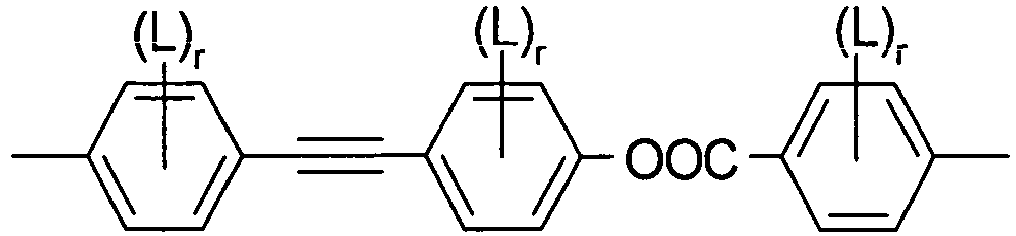
IIf - L is in each occurrence independently of each other F or Cl, preferably F and
- r is in each occurrence independently of each other 0, 1, 2 or 3, preferably 0, 1 or 2.
- The group


- In case of compounds with a unpolar group, R11 and R12 are preferably alkyl with up to 15 C atoms or alkoxy with 2 to 15 C atoms.
- If R11 or R12 is an alkyl or alkoxy radical, i.e. where the terminal CH2 group is replaced by -O-, this may be straight-chain or branched. It is preferably straight-chain, has 2, 3, 4, 5, 6, 7 or 8 carbon atoms and accordingly is preferably ethyl, propyl, butyl, pentyl, hexyl, heptyl, octyl, ethoxy, propoxy, butoxy, pentoxy, hexoxy, heptoxy or octoxy, furthermore methyl, nonyl, decyl, undecyl, dodecyl, tridecyl, tetradecyl, pentadecyl, nonoxy, decoxy, undecoxy, dodecoxy, tridecoxy or tetradecoxy, for example.
- Oxaalkyl, i.e. where one CH2 group is replaced by -O-, is preferably straight-chain 2-oxapropyl (=methoxymethyl), 2- (=ethoxymethyl) or 3-oxabutyl (=2-methoxyethyl), 2-, 3- or 4-oxapentyl, 2-, 3-, 4- or 5-oxahexyl, 2-, 3-, 4-, 5- or 6-oxaheptyl, 2-, 3-, 4-, 5-, 6- or 7-oxaoctyl, 2-, 3-, 4-, 5-, 6-, 7- or 8-oxanonyl or 2-, 3-, 4-, 5-, 6-,7-, 8- or 9-oxadecyl, for example.
- In case of a compounds with a terminal polar group, R11 and R12 are selected from CN, NO2, halogen, OCH3, OCN, SCN, CORx, COORx or a mono- oligo- or polyfluorinated alkyl or alkoxy group with 1 to 4 C atoms. Rx is optionally fluorinated alkyl with 1 to 4, preferably 1 to 3 C atoms. Halogen is preferably F or Cl.
- Especially preferably R11 and R12 in formula I are selected of H, F, Cl, CN, NO2, OCH3, COCH3, COC2H5, COOCH3, COOC2H5, CF3, C2F5, OCF3, OCHF2, and OC2F5, in particular of H, F, Cl, CN, OCH3 and OCF3, especially of H, F, CN and OCF3.
- In addition, compounds of formula I containing an achiral branched group R11 and/or R12 may occasionally be of importance, for example, due to a reduction in the tendency towards crystallisation. Branched groups of this type generally do not contain more than one chain branch. Preferred achiral branched groups are isopropyl, isobutyl (=methylpropyl), isopentyl (=3-methylbutyl), isopropoxy, 2-methyl-propoxy and 3-methylbutoxy.
- The spacer group Sp1 is preferably a linear or branched alkylene group having 1, 3 or 5 to 40 C atoms, in particular 1, 3 or 5 to 25 C atoms, very preferably 1, 3 or 5 to 15 C atoms, and most preferably 5 to 15 C atoms, in which, in addition, one or more non-adjacent and non-terminal CH2 groups may be replaced by -O-, -S-, -NH-, -N(CH3)-, -CO-, -O-CO-, -S-CO-, -O-COO-, -CO-S-, -CO-O-, -CH(halogen)-, -CH(CN)-, -CH=CH- or -C≡C-.
- "Terminal" CH2 groups are those directly bonded to the mesogenic groups. Accordingly, "non-terminal" CH2 groups are not directly bonded to the mesogenic groups MG11 and MG12.
- Typical spacer groups are for example -(CH2)o-, -(CH2CH2O)p-CH2CH2-, with o being an integer from 5 to 40, in particular from 5 to 25, very preferably from 5 to 15, and p being an integer from 1 to 8, in particular 1, 2, 3 or 4.
- Preferred spacer groups are pentylene, hexylene, heptylene, octylene, nonylene, decylene, undecylene, dodecylene, octadecylene, diethyleneoxyethylene, dimethyleneoxybutylene, pentenylene, heptenylene, nonenylene and undecenylene, for example.
- Especially preferred are inventive compounds of formula I wherein Sp is denoting alkylene with 5 to 15 C atoms. Straight-chain alkylene groups are especially preferred.
- Preferred are spacer groups with even numbers of a straight-chain alkylene having 6, 8, 10, 12 and 14 C atoms.
- In another embodiment of the present invention are the spacer groups preferably with odd numbers of a straight-chain alkylene having 5, 7, 9, 11, 13 or 15 C atoms. Very preferred are straight-chain alkylene spacers having 7, 9, and 11 C atoms.
- Especially preferred are inventive compounds of formula I wherein Sp is denoting complete deuterated alkylene with 5 to 15 C atoms. Very preferred are deuterated straight-chain alkylene groups. Most preferred are partially deuterated straight-chain alkylene groups.
- Preferred are compounds of formula I wherein the mesogenic groups R11-MG11- X11- and R12-MG12- X12- are different from each other. In another embodiment compounds of formula I wherein R11-MG11- X11- and R12-MG12- X12- in formula I are identical to each other.
- Preferred compounds of formula I are selected from the group of compounds of formulae IA to IB


- Particularly preferred compounds are selected from the group of formulae given above, which bear 0, 2 or 4 F atoms in lateral positions (i.e. as L).
- The compounds of formula I can be synthesized according to or in analogy to methods which are known per se and which are described in standard works of organic chemistry such as, for example, Houben-Weyl, Methoden der organischen Chemie, Thieme-Verlag, Stuttgart. A preferred method of preparation can be taken from the following synthesis schemes.
- The compounds of formula I are preferably accessible according to the following general reaction schemes.
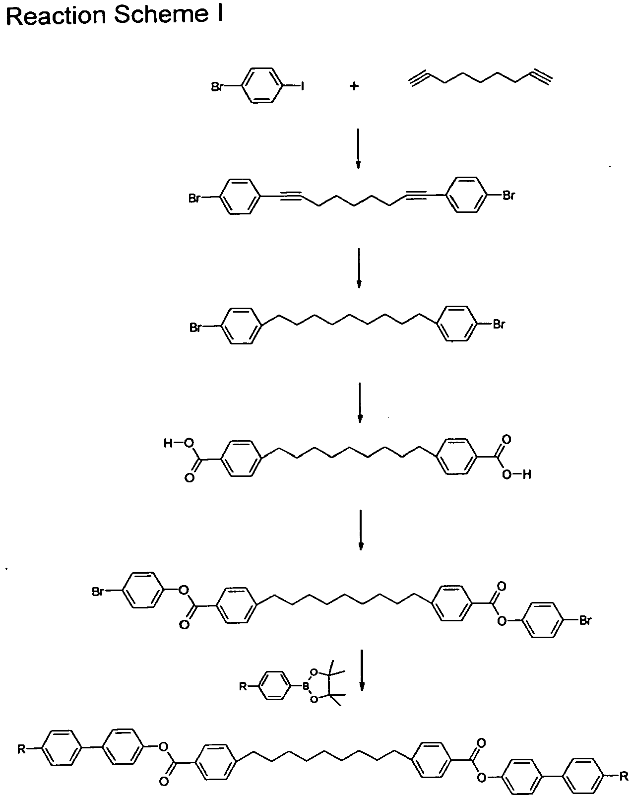
- a) Cul, Pd(PPh3)2Cl2,Triethylamine, 30°C;
- b) [H2], Pd/C;
- c) n-BuLi, CO2, -70°C;
- d) DCC, DMAP, DCM, 25°C; and
- e) Pd(PPh3)2Cl2, NaCO3, THF, under reflux.
- All phenylene moieties shown in this scheme and in the following schemes may independently of each other be optionally bearing one, two or three, preferably one or two, F atoms or one Cl atom or one Cl and one F atom. An exemplary reaction scheme for the preparation of such a fluorinated compound is shown in the following scheme.
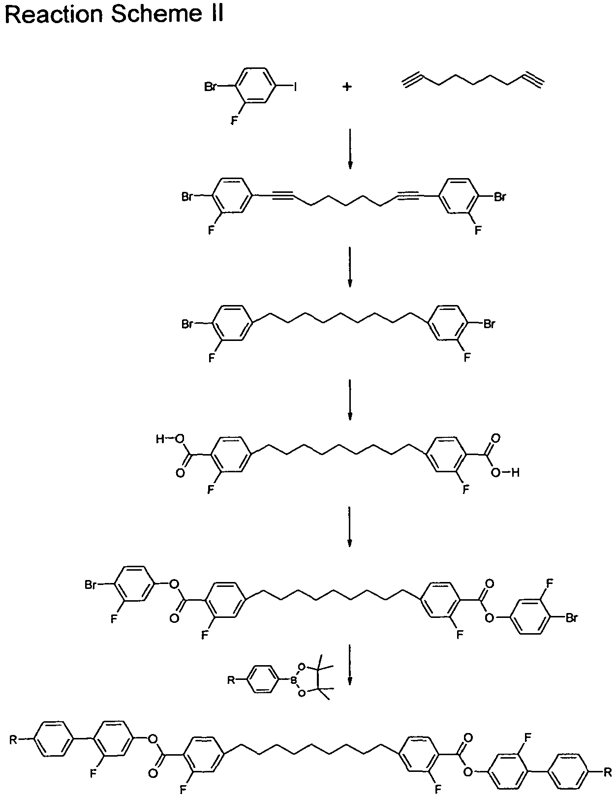

- a) benzylbromide, K2CO3 butanone, 80°C;
- b) Cul, Pd(PPh3)2Cl2,Triethylamine, 30°C;
- c) [H2], Pd/C; and
- d) K2CO3, butanone, 80°C.
- a) Cul, Pd(PPh3)2Cl2,Triethytamine, 30°C;
- b) [H2], Pd/C;
- c) n-BuLi, THF, -70 0°C, CO2;
- d) HSC3H6SH, CF3SO3H,130°C; and
- e)N(C2H5)3, 3HF.N(C2H5)3, -70°C.
- a) (i) HBr, 0°C; (ii) H2O2, 0°C;
- b) DCC, DMAP, DCM;
- c1)AlCl3, S(CH3)2, DCM, 0°C;
- c2) K2CO3, butanone, 80°C; and
- d) K2CO3, butanone, 80°C.
- Another object of the invention is the use of bimesogenic compounds of formula I in liquid crystalline media.
- Compounds of formula I, when added to a nematic liquid crystalline mixture, producing a phase below the nematic. In this context, a first indication of the influence of bimesogenic compounds on nematic liquid crystal mixtures was reported by Barnes, P.J., Douglas, A.G., Heeks, S.K., Luckhurst, G.R., Liquid Crystals, 1993, Vol.13, No.4, 603- 613. This reference exemplifies highly polar alkyl spacered dimers and perceives a phase below the nematic, concluding it is a type of smectic.
- A photo evidence of an existing mesophase below the nematic phase was published by Henderson, P.A., Niemeyer, O., Imrie, C.T. in Liquid Crystals, 2001, Vol. 28, No.3, 463-472, which was not further investigated.
- In Liquid Crystals, 2005, Vol. 32, No. 11-12, 1499-1513 Henderson, P.A., Seddon, J.M. and Imrie, C.T. reported, that the new phase below the nematic belonged in some special examples to a smectic C phase. A additional nematic phase below the first nematic was reported by Panov, V.P., Ngaraj, M., Vij, J.K., Panarin, Y.P., Kohlmeier, A., Tamba, M.G., Lewis, R.A. and Mehl, G.H. in Phys.Rev.Lett. 2010, 105, 1678011 - 1678014.
- In this context, liquid crystal mixtures comprising the new and inventive bimesogenic compounds of formula I show also a novel mesophase that is being assigned as a second nematic phase. This mesophase exists at a lower temperature than the original nematic liquid crystalline phase and has been observed in the unique mixture concepts presented by this application.
- Accordingly, the bimesogenic compounds of formula I according to the present invention allow the second nematic phase to be induced in nematic mixtures that do not have this phase normally. Furthermore, varying the amounts of compounds of formula I allow the phase behaviour of the second nematic to be tailored to the required temperature.
- The invention thus relates to a liquid-crystalline medium which comprises at least one compound of the formula I.
- Some preferred embodiments of the mixtures according to the invention are indicated below.
- Preferred are compounds of formula I wherein the mesogenic groups MG11 and MG12 at each occurrence independently from each other comprise one, two or three six-membered rings, preferably two or three six-membered rings.
- Particularly preferred are the partial formulae II-1, II-4, II-6, II-7, II-13, II-14, II-15, II-16, II-17 and II-18.
Preferably R11 and R12 in formula I are selected of H, F, Cl, CN, NO2, OCH3, COCH3, COC2H5, COOCH3, COOC2H5, CF3, C2F5, OCF3, OCHF2, and OC2F5, in particular of H, F, Cl, CN, OCH3 and OCF3, especially of H, F, CN and OCF3. - Typical spacer groups (Sp1) are for example -(CH2)o-, -(CH2CH2O)p-CH2CH2-, with o being 1, 3 or an integer from 5 to 40, in particular from 1, 3 or 5 to 25, very preferably from 5 to 15, and p being an integer from 1 to 8, in particular 1, 2, 3 or 4.
- Preferred are compounds of formula I wherein R11-MG11-X11- and R12-MG12-X12- in formula I are identical.
The media according to the invention preferably comprise one, two, three, four or more, preferably one, two or three, compounds of the formula I. - The amount of compounds of formula I in the liquid crystalline medium is preferably from 1 to 50 %, in particular from 5 to 40 %, very preferably 10 to 30 % by weight of the total mixture.
- In a preferred embodiment the liquid crystalline medium according to the present invention comprises additionally one or more compounds of formula III, like those or similar to those known from
GB 2 356 629
R31-MG31-X31-Sp3-X32-MG32-R32 III
wherein - R31 and R32
- are each independently H, F, Cl, CN, NCS or a straight-chain or branched alkyl group with 1 to 25 C atoms which may be unsubstituted, mono- or polysubstituted by halogen or CN, it being also possible for one or more non-adjacent CH2 groups to be replaced, in each case independently from one another, by -O-, -S-, -NH-, -N(CH3)-, -CO-, -COO-, -OCO-, -O-CO-O-,-S-CO-,
-CO-S-, -CH=CH-, -CH=CF-, -CF=CF- or -C≡C- in such a manner that oxygen atoms are not linked directly to one another, - MG31 and MG32
- are each independently a mesogenic group,
- Sp3
- is a spacer group comprising 5 to 40 C atoms, wherein one or more non-adjacent CH2 groups may also be replaced by -O-, -S-, -NH-, -N(CH3)-, -CO-, -O-CO-, -S-CO-, -O-COO-, -CO-S-, -CO-O-, -CH(halogen)-, -CH(CN)-, -CH=CH- or -C≡C-, and
- X31 and X32
- are each independently -O-, -S-, -CO-, -COO-, -OCO-, -O-CO-O-, -CO-NH-, -NH-CO-, -CH2CH2-, -OCH2-,-CH2O-, -SCH2-, -CH2S-, -CH=CH-, -CH=CH-COO-, -OCO-CH=CH-, -C≡C- or a single bond, and
- The mesogenic groups MG31 and MG32 are preferably selected of formula II.
- Especially preferred are compounds of formula III wherein R31-MG31-X31- and R32-MG32-X32- are identical.
- Another preferred embodiment of the present invention relates to compounds of formula III wherein R31-MG31-X31- and R32-MG32-X32- are different.
- Especially preferred are compounds of formula III wherein the mesogenic groups MG31 and MG32 comprise one, two or three six-membered rings very preferably are the mesogenic groups selected from formula II as listed below.
- For MG31 and MG32 in formula III are particularly preferred are the subformulae II-1, II-4, II-6, II-7, II-13, II-14, II-15, II-16, II-17 and II-18. In these preferred groups Z in each case independently has one of the meanings of Z1 as given in formula II. Preferably Z is -COO-, -OCO-, -CH2CH2-, -C≡C- or a single bond.
- Very preferably the mesogenic groups MG31 and MG32 are selected from the formulae IIa to IIo and their mirror images.
- In case of compounds with a unon-polar group, R31 and R32 are preferably alkyl with up to 15 C atoms or alkoxy with 2 to 15 C atoms.
If R31 or R32 is an alkyl or alkoxy radical, i.e. where the terminal CH2 group is replaced by -O-, this may be straight-chain or branched. It is preferably straight-chain, has 2, 3, 4, 5, 6, 7 or 8 carbon atoms and accordingly is preferably ethyl, propyl, butyl, pentyl, hexyl, heptyl, octyl, ethoxy, propoxy, butoxy, pentoxy, hexoxy, heptoxy, or octoxy, furthermore methyl, nonyl, decyl, undecyl, dodecyl, tridecyl, tetradecyl, pentadecyl, nonoxy, decoxy, undecoxy, dodecoxy, tridecoxy or tetradecoxy, for example. - Oxaalkyl, i.e. where one CH2 group is replaced by -O-, is preferably straight-chain 2-oxapropyl (=methoxymethyl), 2- (=ethoxymethyl) or 3-oxabutyl (=2-methoxyethyl), 2-, 3-, or 4-oxapentyl, 2-, 3-, 4-, or 5-oxahexyl, 2-, 3-, 4-, 5-, or 6-oxaheptyl, 2-, 3-, 4-, 5-, 6- or 7-oxaoctyl, 2-, 3-, 4-, 5-, 6-, 7- or 8-oxanonyl or 2-, 3-, 4-, 5-, 6-,7-, 8- or 9-oxadecyl, for example.
- In case of a compounds with a terminal polar group, R31 and R32 are selected from CN, NO2, halogen, OCH3, OCN, SCN, CORx, COORx or a mono- oligo- or polyfluorinated alkyl or alkoxy group with 1 to 4 C atoms. Rx is optionally fluorinated alkyl with 1 to 4, preferably 1 to 3 C atoms. Halogen is preferably F or Cl.
- Especially preferably R31 and R32 in formula III are selected of F, Cl, CN, NO2, OCH3, COCH3, COC2H5, COOCH3, COOC2H5, CF3, C2F5, OCF3, OCHF2, and OC2F5, in particular of F, Cl, CN, OCH3 and OCF3.
- As for the spacer group Sp3 in formula III all groups can be used that are known for this purpose to the skilled in the art. The spacer group Sp is preferably a linear or branched alkylene group having 5 to 40 C atoms, in particular 5 to 25 C atoms, very preferably 5 to 15 C atoms, in which, in addition, one or more non-adjacent CH2 groups may be replaced by -O-, -S-, -NH-, -N(CH3)-, -CO-, -O-CO-, -S-CO-, -O-COO-, -CO-S-, -CO-O-, -CH(halogen)-, -CH(CN)-, -CH=CH- or -C≡C-.
- Typical spacer groups are for example -(CH2)o-, -(CH2CH2O)p-CH2CH2-, -CH2CH2-S-CH2CH2- or -CH2CH2-NH-CH2CH2-, with o being an integer from 5 to 40, in particular from 5 to 25, very preferably from 5 to 15, and p being an integer from 1 to 8, in particular 1, 2, 3 or 4.
- Preferred spacer groups are pentylene, hexylene, heptylene, octylene, nonylene, decylene, undecylene, dodecylene, octadecylene, diethyleneoxyethylene, dimethyleneoxybutylene, pentenylene, heptenylene, nonenylene and undecenylene, for example.
- Especially preferred are inventive compounds of formula III wherein Sp3 is denoting alkylene with 5 to 15 C atoms. Straight-chain alkylene groups are especially preferred.
- In another preferred embodiment of the invention the chiral compounds of formula III comprise at least one spacer group Sp1 that is a chiral group of the formula IV.
- X31 and X32 in formula III denote preferably -O-, -CO-, -COO-, -OCO-, -O-CO-O- or a single bond. Particularly preferred are the following compounds selected from formulae III-1 to III-4:


- Particularly preferred mixtures according to the invention comprise one or more compounds of the formulae III-1a to III-1e and III-3a to III-3b.




- In a preferred embodiment of the invention the liquid crystalline medium is consisting of 2 to 25, preferably 3 to 15 compounds of formula III.
- The amount of compounds of formula III in the liquid crystalline medium is preferably from 10 to 95 %, in particular from 15 to 90 %, very preferably 20 to 85 % by weight of the total mixture.
- Preferably, the proportion of compounds of the formulae III-1a and/or III-1b and/or III-1c and/or III-1e and or III-3a and/or III-3b in the medium as a whole is preferably at least 70 % by weight.
- Particularly preferred media according to the invention comprise at least one or more chiral dopants which themselves do not necessarily have to show a liquid crystalline phase and give good uniform alignment themselves.
- Especially preferred are chiral dopants selected from formula IV


wherein E and F are each independently 1,4-phenylene or trans-1,4-cyclohexylene, v is 0 or 1, Z0 is -COO-, -OCO-, -CH2CH2- or a single bond, and R is alkyl, alkoxy or alkanoyl with 1 to 12 C atoms. - The compounds of formula IV and their synthesis are described in
WO 98/00428 GB 2,328,207 - Especially preferred are chiral dopants with a high helical twisting power (HTP), in particular those disclosed in
WO 98/00428 - Further typically used chiral dopants are e.g. the commercially available R/S-5011, CD-1, R/S-811 and CB-15 (from Merck KGaA, Darmstadt, Germany).
- The above mentioned chiral compounds R/S-5011 and CD-1 and the compounds of formula IV and V exhibit a very high helical twisting power (HTP), and are therefore particularly useful for the purpose of the present invention.
- The liquid crystalline medium preferably comprises preferably 1 to 5, in particular 1 to 3, very preferably 1 or 2 chiral dopants, preferably selected from the above formula IV, in particular CD-1, and/or formula V and/or R-5011 or S-5011, very preferably the chiral compound is R-5011, S-5011 or CD-1.
- The amount of chiral compounds in the liquid crystalline medium is preferably from 1 to 20 %, in particular from 1 to 15 %, very preferably 1 to 10 % by weight of the total mixture.
- Further preferred are liquid crystalline media comprising one or more additives selected from the following formula VI

- R5
- is alkyl, alkoxy, alkenyl or alkenyloxy with up to 12 C atoms,
- L1 through L4
- are each independently H or F,
- Z2
- is -COO-, -CH2CH2- or a single bond,
- m
- is 1 or 2
- Particularly preferred compounds of formula VI are selected from the following formulae


- The liquid crystalline medium preferably comprises preferably 1 to 5, in particular 1 to 3, very preferably 1 or 2, preferably selected from the above formulae VIa to VIf, very preferably from formulae VIf.
- The amount of suitable additives of formula VI in the liquid crystalline medium is preferably from 1 to 20 %, in particular from 1 to 15 %, very preferably 1 to 10 % by weight of the total mixture.
- The liquid crystal media according to the present invention may contain further additives in usual concentrations. The total concentration of these further constituents is in the range of 0.1 % to 10 %, preferably 0.1 % to 6 %, based on the total mixture. The concentrations of the individual compounds used each are preferably in the range of 0.1 % to 3 %. The concentration of these and of similar additives is not taken into consideration for the values and ranges of the concentrations of the liquid crystal components and compounds of the liquid crystal media in this application. This also holds for the concentration of the dichroic dyes used in the mixtures, which are not counted when the concentrations of the compounds respectively the components of the host medium are specified. The concentration of the respective additives is always given relative to the final doped mixture.
- The liquid crystal media according to the present invention consists of several compounds, preferably of 3 to 30, more preferably of 4 to 20 and most preferably of 4 to 16 compounds. These compounds are mixed in conventional way. As a rule, the required amount of the compound used in the smaller amount is dissolved in the compound used in the greater amount. In case the temperature is above the clearing point of the compound used in the higher concentration, it is particularly easy to observe completion of the process of dissolution. It is, however, also possible to prepare the media by other conventional ways, e.g. using so called pre-mixtures, which can be e.g. homologous or eutectic mixtures of compounds or using so called multi-bottle-systems, the constituents of which are ready to use mixtures themselves.
- Particularly preferred mixture concepts are indicated below: (the acronyms used are explained in Table A).
- The mixtures according to the invention preferably comprise
- one or more compounds of formula I in a total concentration in the range from 1 to 50 %, in particular from 5 to 40 %, very preferably 10 to 30 % by weight of the total mixture
- one or more compounds of formula III in a total concentration in the range from 10 to 95 %, in particular from 15 to 90 %, very preferably 20 to 85 % by weight of the total mixture, preferably these compounds are selected from formulae III-1a to III-1e and III-3a to III-3b especially preferred they comprise
- N-PGI-ZI-n-Z-GP-N, preferably N-PGI-ZI-7-Z-GP-N and/or N-PGI-ZI-9-Z-GP-N preferably in concentrations > 5 %, in particular 10-30 %, based on the mixture as a whole,
- F-UIGI-ZI-n-Z-GU-F, preferably F-UIGI-ZI-9-Z-GU-F, preferably in concentrations > 5 %, in particular 10-30 %, based on the mixture as a whole,
- F-PGI-O-n-O-PP-N, preferably F-PGI-O-9-O-PP-, preferably in concentrations of > 1 %, in particular 1-20 %, based on the mixture as a whole,
- N-PP-O-n-O-PG-OT, preferably N-PP-O-7-O-PG-OT, preferably in concentrations of > 5 %, in particular 5-30 %, based on the mixture as a whole,
- N-PP-O-n-O-GU-F, preferably N-PP-O-9-O-GU-F, preferably in concentrations of > 1 %, in particular 1-20 %, based on the mixture as a whole,
- F-PGI-O-n-O-GP-F, preferably F-PGI-O-7-O-GP-F and/or F-PGI-O-9-O-GP-F preferably in concentrations of > 1 %, in particular 1-20 %, based on the mixture as a whole,
- N-GIGIGI-n-GGG-N, in particular N-GIGIGI-9-GGG-N, preferably in concentration > 5 %, in particular 10-30 %, based on the mixture as a whole,
- N-PGI-n-GP-N, preferably N-PGI-9-GP-N, preferably in concentrations > 5 %, in particular 15-50 %, based on the mixture as a whole,
- one or more suitable additives of formula VI in a total concentration in the range from 1 to 20 %, in particular from 1 to 15 %, very preferably 1 to 10 % by weight of the total mixture, preferably are these compounds selected from formula VIa to VIf, especially preferred they comprise
- PP-n-N, preferably in concentrations of > 1 %, in particular 1-20 %, based on the mixture as a whole,
- one or more chiral compounds preferably in a total concentration in the range from 1 to 20 %, in particular from 1 to 15 %, very preferably 1 to 10 % by weight of the total mixture, preferably these compounds are selected from formula IV, V, and R-5011 or S-5011, especially preferred they comprise
- R-5011, S-5011 or CD-1, preferably in a concentration of > 1 %, in particular 1-20 %, based on the mixture as a whole.
- The bimesogenic compounds of formula I and the liquid crystalline media comprising them can be used in liquid crystal displays, such as STN, TN, AMD-TN, temperature compensation, guest-host, phase change or surface stabilized or polymer stabilized cholesteric texture (SSCT, PSCT) displays, in particular in flexoelectric devices, in active and passive optical elements like polarizers, compensators, reflectors, alignment layers, color filters or holographic elements, in adhesives, synthetic resins with anisotropic mechanical properties, cosmetics, diagnostics, liquid crystal pigments, for decorative and security applications, in nonlinear optics, optical information storage or as chiral dopants.
- The compounds of formula I and the mixtures obtainable thereof are particularly useful for flexoelectric liquid crystal display. Thus, another object of the present invention is a flexoelectric display comprising one or more compounds of formula I or comprising a liquid crystal medium comprising one or more compounds of formula I.
- The inventive bimesogenic compounds of formula I and the mixtures thereof can be aligned in their cholesteric phase into different states of orientation by methods that are known to the expert, such as surface treatment or electric fields. For example, they can be aligned into the planar (Grandjean) state, into the focal conic state or into the homeotropic state. Inventive compounds of formula I comprising polar groups with a strong dipole moment can further be subjected to flexoelectric switching, and can thus be used in electrooptical switches or liquid crystal displays.
- The switching between different states of orientation according to a preferred embodiment of the present invention is exemplarily described below in detail for a sample of an inventive compound of formula I.
- According to this preferred embodiment, the sample is placed into a cell comprising two plane-parallel glass plates coated with electrode layers, e.g. ITO layers, and aligned in its cholesteric phase into a planar state wherein the axis of the cholesteric helix is oriented normal to the cell walls. This state is also known as Grandjean state, and the texture of the sample, which is observable e.g. in a polarization microscope, as Grandjean texture. Planar alignment can be achieved e.g. by surface treatment of the cell walls, for example by rubbing and/or coating with an alignment layer such as polyimide.
- A Grandjean state with a high quality of alignment and only few defects can further be achieved by heating the sample to the isotropic phase, subsequently cooling to the chiral nematic phase at a temperature close to the chiral nematic-isotropic phase transition, and rubbing the cell.
- In the planar state, the sample shows selective reflection of incident light, with the central wavelength of reflection depending on the helical pitch and the mean refractive index of the material.
- When an electric field is applied to the electrodes, for example with a frequency from 10 Hz to 1 kHz, and an amplitude of up to 12 Vrms /□m, the sample is being switched into a homeotropic state where the helix is unwound and the molecules are oriented parallel to the field, i.e. normal to the plane of the electrodes. In the homeotropic state, the sample is transmissive when viewed in normal daylight, and appears black when being put between crossed polarizers.
- Upon reduction or removal of the electric field in the homeotropic state, the sample adopts a focal conic texture, where the molecules exhibit a helically twisted structure with the helical axis being oriented perpendicular to the field, i.e. parallel to the plane of the electrodes. A focal conic state can also be achieved by applying only a weak electric field to a sample in its planar state. In the focal conic state the sample is scattering when viewed in normal daylight and appears bright between crossed polarizers.
- A sample of an inventive compound in the different states of orientation exhibits different transmission of light. Therefore, the respective state of orientation, as well as its quality of alignment, can be controlled by measuring the light transmission of the sample depending on the strength of the applied electric field. Thereby it is also possible to determine the electric field strength required to achieve specific states of orientation and transitions between these different states.
- In a sample of an inventive compound of formula I, the above described focal conic state consists of many disordered birefringent small domains. By applying an electric field greater than the field for nucleation of the focal conic texture, preferably with additional shearing of the cell, a uniformly aligned texture is achieved where the helical axis is parallel to the plane of the electrodes in large, well-aligned areas. In accordance with the literature on state of the art chiral nematic materials, such as P. Rudquist et al., Liq. Cryst. 23 (4), 503 (1997), this texture is also called uniformly-lying helix (ULH) texture. This texture is required to characterize the flexoelectric properties of the inventive compound.
- The sequence of textures typically observed in a sample of an inventive compound of formula I on a rubbed polyimide substrate upon increasing or decreasing electric field is given below:

- Starting from the ULH texture, the inventive flexoelectric compounds and mixtures can be subjected to flexoelectric switching by application of an electric field. This causes rotation of the optic axis of the material in the plane of the cell substrates, which leads to a change in transmission when placing the material between crossed polarizers. The flexoelectric switching of inventive materials is further described in detail in the introduction above and in the examples.
- It is also possible to obtain the ULH texture, starting from the focal conic texture, by applying an electric field with a high frequency, of for example 10 kHz, to the sample whilst cooling slowly from the isotropic phase into the cholesteric phase and shearing the cell. The field frequency may differ for different compounds.
- The bimesogenic compounds of formula I are particularly useful in flexoelectric liquid crystal displays as they can easily be aligned into macroscopically uniform orientation, and lead to high values of the elastic constant k11 and a high flexoelectric coefficient e in the liquid crystal medium.
- The liquid crystal medium preferably exhibits a k11 < 1×10⁻¹⁰ N, preferably < 2×10-11 N, and a flexoelectric coefficient e > 1×10-11 C/m, preferably > 1×10⁻¹⁰ C/m.
- Apart from the use in flexoelectric devices, the inventive bimesogenic compounds as well as mixtures thereof are also suitable for other types of displays and other optical and electrooptical applications, such as optical compensation or polarizing films, color filters, reflective cholesterics, optical rotatory power and optical information storage.
- A further aspect of the present invention relates to a display cell wherein the cell walls exhibit hybrid alignment conditions. The term "hybrid alignment" or orientation of a liquid crystal or mesogenic material in a display cell or between two substrates means that the mesogenic groups adjacent to the first cell wall or on the first substrate exhibit homeotropic orientation and the mesogenic groups adjacent to the second cell wall or on the second substrate exhibit planar orientation.
- The term "homeotropic alignment" or orientation of a liquid crystal or mesogenic material in a display cell or on a substrate means that the mesogenic groups in the liquid crystal or mesogenic material are oriented substantially perpendicular to the plane of the cell or substrate, respectively.
- The term "planar alignment" or orientation of a liquid crystal or mesogenic material in a display cell or on a substrate means that the mesogenic groups in the liquid crystal or mesogenic material are oriented substantially parallel to the plane of the cell or substrate, respectively.
- A flexoelectric display according to a preferred embodiment of the present invention comprises two plane parallel substrates, preferably glass plates covered with a transparent conductive layer such as indium tin oxide (ITO) on their inner surfaces, and a flexoelectric liquid crystalline medium provided between the substrates, characterized in that one of the inner substrate surfaces exhibits homeotropic alignment conditions and the opposite inner substrate surface exhibits planar alignment conditions for the liquid crystalline medium.
- Planar alignment can be achieved e.g. by means of an alignment layer, for example a layer of rubbed polyimide or sputtered SiOx, that is applied on top of the substrate.
- Alternatively it is possible to directly rub the substrate, i.e. without applying an additional alignment layer. For example, rubbing can be achieved by means of a rubbing cloth, such as a velvet cloth, or with a flat bar coated with a rubbing cloth. In a preferred embodiment of the present invention rubbing is achieved by means of a at least one rubbing roller, like e.g. a fast spinning roller that is brushing across the substrate, or by putting the substrate between at least two rollers, wherein in each case at least one of the rollers is optionally covered with a rubbing cloth. In another preferred embodiment of the present invention rubbing is achieved by wrapping the substrate at least partially at a defined angle around a roller that is preferably coated with a rubbing cloth.
- Homeotropic alignment can be achieved e.g. by means of an alignment layer coated on top of the substrate. Suitable aligning agents used on glass substrates are for example alkyltrichlorosilane or lecithine, whereas for plastic substrate thin layers of lecithine, silica or high tilt polyimide orientation films as aligning agents may be used. In a preferred embodiment of the invention silica coated plastic film is used as a substrate.
- Further suitable methods to achieve planar or homeotropic alignment are described for example in J. Cognard, Mol.Cryst.Liq.Cryst. 78, Supplement 1, 1-77 (1981).
- By using a display cell with hybrid alignment conditions, a very high switching angle of flexoelectric switching, fast response times and a good contrast can be achieved.
- The flexoelectric display according to present invention may also comprise plastic substrates instead of glass substrates. Plastic film substrates are particularly suitable for rubbing treatment by rubbing rollers as described above.
- Another object of the present invention is that compounds of formula I, when added to a nematic liquid crystalline mixture, produce a phase below the nematic.
- Accordingly, the bimesogenic compounds of formula I according to the present invention allow the second nematic phase to be induced in nematic mixtures that do not show evidence of this phase normally. Furthermore, varying the amounts of compounds of formula I allow the phase behaviour of the second nematic to be tailored to the required temperature.
- Examples for this are given and the mixtures obtainable thereof are particularly useful for flexoelectric liquid crystal display. Thus, another object of the present invention is liquid crystal media comprising one or more compounds of formula I exhibiting a second nematic phase.
- Without further elaboration, it is believed that one skilled in the art can, using the preceding description, utilize the present invention to its fullest extent. The following examples are, therefore, to be construed as merely illustrative and not limitative of the remainder of the disclosure in any way whatsoever.
- Unless the context clearly indicates otherwise, as used herein plural forms of the terms herein are to be construed as including the singular form and vice versa.
Throughout the description and claims of this specification, the words "comprise" and "contain" and variations of the words, for example "comprising" and "comprises", mean "including but not limited to", and are not intended to (and do not) exclude other components. - Throughout the present application it is to be understood that the angles of the bonds at a C atom being bound to three adjacent atoms, e.g. in a C=C or C=O double bond or e.g. in a benzene ring, are 120° and that the angles of the bonds at a C atom being bound to two adjacent atoms, e.g. in a C=C or in a C=N triple bond or in an allylic position C=C=C are 180°, unless these angles are otherwise restricted, e.g. like being part of small rings, like 3-, 5- or 5-atomic rings, notwithstanding that in some instances in some structural formulae these angles are not represented exactly.
- It will be appreciated that variations to the foregoing embodiments of the invention can be made while still falling within the scope of the invention. Each feature disclosed in this specification, unless stated otherwise, may be replaced by alternative features serving the same, equivalent or similar purpose. Thus, unless stated otherwise, each feature disclosed is one example only of a generic series of equivalent or similar features.
- All of the features disclosed in this specification may be combined in any combination, except combinations where at least some of such features and/or steps are mutually exclusive. In particular, the preferred features of the invention are applicable to all aspects of the invention and may be used in any combination. Likewise, features described in non-essential combinations may be used separately (not in combination).
- The total concentration of all compounds in the media according to this application is 100 %.
- In the foregoing and in the following examples, unless otherwise indicated, all temperatures are set forth uncorrected in degrees Celsius and all parts and percentages are by weight.
- The following abbreviations are used to illustrate the liquid crystalline phase behavior of the compounds: K = crystalline; N = nematic; N2 = second nematic; S = smectic; Ch = cholesteric; I = isotropic; Tg = glass transition. The numbers between the symbols indicate the phase transition temperatures in °C.
- In the present application and especially in the following examples, the structures of the liquid crystal compounds are represented by abbreviations, which are also called "acronyms". The transformation of the abbreviations into the corresponding structures is straight forward according to the following three tables A to C.
- All groups CnH2n+1, CmH2m+1, and ClH2l+1are preferably straight chain alkyl groups with n, m and I C-atoms, respectively, all groups CnH2n, CmH2m and ClH2l, are preferably (CH2)n, (CH2)m and (CH2)l, respectively and -CH=CH- preferably is trans- respectively E vinylene.
- Table A lists the symbols used for the ring elements, table B those for the linking groups and table C those for the symbols for the left hand and the right hand end groups of the molecules.
- Table D lists exemplary molecular structures together with their respective codes.
Table A: Ring Elements C 
P 
D 
DI 
A 
AI 
G 
GI 
G(CI) 
GI(CI) 
G(1) 
GI(1) 
U 
UI 
Y 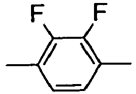
M 
MI 
N 
NI 
np 
n3f 
n3fl 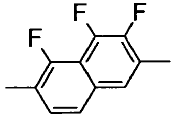
th 
thl 
th2f 
th2fl 
o2f 
o2fl 
dh 
K 
KI 
L 
LI 
F 
FI 
Table B: Linking Groups n (-CH2-)n "n" is an integer except 0 and 2 E -CH2-CH2- V -CH=CH- T -C=C- W -CF2-CF2- B -CF=CF- Z -CO-O- ZI -O-CO- X -CF=CH- XI -CH=CF- 1O -CH2-O O1 -O-CH2- Q -CF2-O- QI -O-CF2- Table C: End Groups Left hand side, used alone or in combination with others Right hand side, used alone or in combination with others -n- CnH2n+1- -n -CnH2n+1 -nO- CnH2n+1O- -nO -O-CnH2n+1 -V- CH2=CH- -V -CH=CH2 -nV- CnH2n+1-CH=CH- -nV -CnH2n-CH=CH2 -Vn- CH2=CH- CnH2n- -Vn -CH=CH-CnH2n+1 -nVm- CnH2n+1-CH=CH-CmH2m- -nVm -CnH2n-CH=CH-CmH2m+1 -N- N=C- -N -C≡N -S- S=C=N- -S -N=C=S -F- F- -F -F -CL- Cl- -CL -Cl -M- CFH2- -M -CFH2 -D- CF2H- -D -CF2H -T- CF3- -T -CF3 -MO- CFH2O- -OM -OCFH2 -DO- CF2HO- -OD -OCF2H -TO- CF3O- -OT -OCF3 -A- H-C=C- -A -C≡C-H -nA- CnH2n+1-C≡C- -An -C≡C-CnH2n+1 -NA- N=C-C=C- -AN -C≡C-C≡N Left hand side, used in combination with others only Right hand side, used in combination with others only -...n...- (-CH2-)n -...n... (-CH2-)n -...M...- -CFH- -...M... -CFH- -...D...- -CF2- -...D... -CF2- -...V...- -CH=CH- -...V... -CH=CH- -...Z...- -CO-O- -...Z... -CO-O- -...ZI...- -O-CO- -...ZI... -O-CO- -...K...- -CO- -...K... -CO- -...W...- -CF=CF- -...W... -CF=CF- - Preferably the liquid crystalline media according to the present invention comprise, besides the compound(s) of formula I one or more compounds selected from the group of compounds of the formulae of the following table.
Table D 
F-PGI-O-n-O-GP-F 
F-PG-O-n-O-GIP-F 
N-PP-O-n-O-GU-F 
N-PP-O-n-O-PG-OT 
F-PGI-O-n-O-PP-N 
R-5011 respectively S-5011 
CD-1 
PP-n-N 
F-UIGI-ZI-n-Z-GU-F 
N-PGI-ZI-n-Z-GP-N 
F-PGI-ZI-n-Z-GP-F 
N-GIGIGI-n-GGG-N 
N-PGIUI-n-UGP-N 
N-GIUIGI-n-GUG-N 
N-GIUIP-n-PUG-N 
N-PGI-n-GP-N 
N-PUI-n-UP-N 
N-UIUI-n-UU-N 
N-GIGI-n-GG-N 
N-PGI(1)-n-G(1)P-N 
F-UIGI-n-GU-F 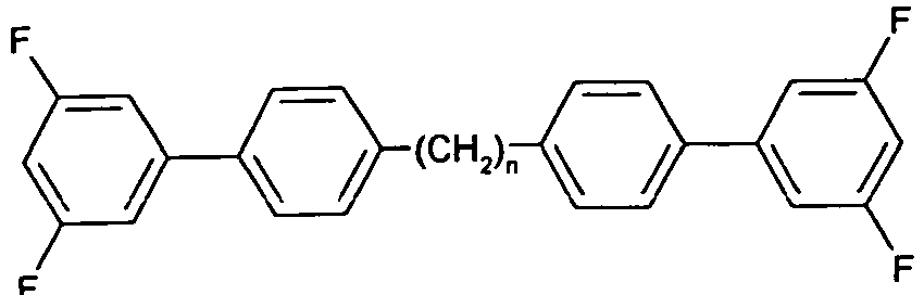
UIP-n-PU 
N-PGI-n-GP-N 
N-PG(1)-n-GI(1)P-N 
N-PZIP-n-PZP-N 
N-GIZIP-n-PZG-N 
N-PZIGI-n-GZP-N 
N-GIZIGI-n-GZG-N 
N-UIZIP-n-PZU-N - The product of the synthesis comparative example 2, step 2.3 (2.50 g, 7.18 mmol), 4-bromomethyl-benzonitrile (2.81 g, 14.4 mmol) and potassium carbonate (1.79 g, 19.9 mmol) are mixed together in ethylmethylketone (50 ml). The reaction mixture is heated under reflux at 80°C for 12 hours. The reaction-mixture is then cooled and the solid precipitate formed is filtered off under vacuum, the filter pad is washed with ether then the solution is concentrated under reduced pressure. The crude product is purified by chromatography through silica, eluted with 30 % DCM in petroleum ether (40-60). The material is then re-crystallised from acetonitrile to yield the desired non symmetrical intermediate alcohol.
- The product from the previous step, step 3.4 (2.15 g, 4.64 mmol), 1-bromomethyl-4-fluorobenzene (1.05 g, 5.56 mmol) and potassium carbonate (1.92 g, 14.0 mmol) are mixed together in ethylmethylketone (50 ml). The reaction mixture is heated under reflux at 80°C for 18 hours. The reaction-mixture is then cooled and solids filtered off under vacuum, the filter pad is washed with diethyl ether then concentrated under reduced pressure. The crude product is purified by chromatography through silica, eluted with 30% DCM in petroleum ether (40-60). The material was then re-crystallised twice from acetonitrile to afford the product.




(= N-PO1P-n-PO1P-F)
(=N-PO1GI-n-GO1P-F)
-

-

- 55.1 g (183 mmol) of the iodobromofluorobenzene and 60 ml tetrahydrofuran are added to a reaction flask, which is evacuated three times and subsequently filled with nitrogen, then treated in an ultrasonic bath to degas the reaction mixture, a procedure shortly referred to as "ultasonication" in this application, for 10 min. with additional evacuation/purging with nitrogen. Pd(PPh3)2Cl2 (1.8 g, 2.6 mmol) and CuI (0.4 g, 2.1 mmol) as catalysts and diisopropylamine (60 ml) are added and the reaction vessel is purged again before being "ultrasonicated" for 10 minutes and then placed in a large water bath to control the reaction temperature.
- 1,8-nonadiyne (10 g, 83 mmol) are added slowly over a time span of 15 minutes A fine precipitate is formed. The reaction mixture is stirred overnight at ambient temperature.
- The reaction mixture is then filtered under vacuum and the filter pad washed with Dichloromethane. The filtrate is concentrated to a semi-solid, which is re-dissolved in dichloromethane before being passed through a silica column to purify. The target product is eluted with additional dichloromethane before final isolation by re-crystallisation from petroleum ether.
-

- The hydrogenation reaction is performed in an "H-Cube"-hydrogenation apparatus. The parameters of the reaction are as follows: Flow rate: 7 ml/min, Mode: 100 % H2, Catalysts: Pt/C, Temperature: 50°C and Pressure: 30 bar.
-

- Anhydrous tetrahydrofuran is charged into a three neck flask together with 9.4 g (19.8 mmol) of the dibromide with the saturated spacer. The flask is evacuated and filled with nitrogen. The reaction mixture is stirred and cooled to a temperature of -75 °C in a bath of acetone cooled by solid CO2.
- Then 31 ml 1.6 M, (49.5 mmol) n-butyl lithium are added drop wise over a time span of 30 minutes while keeping the temperature at -75°C. After 3 hours further stirring 8.7 g (200 mmol) of crushed, solid CO2 are cautiously added to the reaction mixture. A thick white sludge develops and this is stirred for a further 30 minutes before it is hydrolysed by the addition of dilute HCl. The mixture is extracted three times with diethyl ether, and the combined organic material washed with water until neutral. Then toluene is added and the whole solvent is solution is evaporated. The solid the product is isolated and used in the following without further purification.
-

- 4.9 g (24 mmol) of the acid intermediate are added to flask filled with 50 ml dichloromethane. This mixture is thoroughly stirred before 6.5 g (31 mmol) of trifluoroacetic anhydride are added cdropwise over a time span of 5 minutes. The reaction mixture is then stirred further for 5 minutes.
- Then 4.6 g (24.4 mmol) of solid 4-hydroxy-3-fluorobromobenzene are added and the reaction mixture is stirred at a temperature of 35°C. After complete reaction, water is added. The organic and aqueus layers are separated and the aqueous solution is extracted three times with dichloromethane. The combined organic solutions are washed with a solution of sodium carbonate before being dried over magnesium sulphate, filtered and concentrated. The crude product is purified by passing through a silica plug and eluting with a mixture of petrol and dichloromethane (1:2). The final purification is carried out by re-crystallisation from MeCN.
-

- 1.0 g (1.33 mmol) of the bromide intermediate, 0.61 g (2.67 mmol) of 4-cyanophenyl boronate ester, 0.63 g (2.66 mmol) of sodium metaborate octahydrate, 9.0 ml (499 mmol) of water and 37.5 ml (463 mmol) of tetrahydrofuran are filled into a round bottom flask. This mixture is stirred, the flask is evacuated and filled with nitrogen before being "untrasonicated" for 30 minutes. Then 0.075 g (0.107 mmol) of palladium dichloride-(bistriphenylphosphine) are added and the vessel is evacuated then filled with nitrogen. The reaction mixture is heated to a temperature of 80°C for 72 hours under reflux. Then the reaction mixture is cooled, water and diethyl ether are added subsequently. Then the resulting phases are separated. The aqueous phase is extracted twice with diethyl ether, and the combined organic phases are washed twice with water and once with an aquous solution of NaCl. The organic solution is dried over sodium sulphate, filtered and the solvent evaporated. The crude product is purified over a short silica column, eluted with first petrol then with a mixture of petrol/dichloromethane (2:1). The product is isolated after repeated re-crystallisation from acetonitrile.

- This compound has the phase sequence: K 130 Sm 255 N 271 I.

- 4-bromofluorophenol (33.9 g, 0.178 moles), benzylbromide (21.1 ml, 0.178 moles), potassium carbonate (34.4 g, 0.25 moles) and butan-2-one (300ml) are heated together at a temperature of 85°C under reflux overnight. The mixture is cooled, filtered, washed with butanone and diethyl ether and the solvent removed in vacuo. The material is re-crystallised from heptane at -20°C.
- The bromide (44.5 g, 115.8 mmol) from the previous step, triethylamine (89 ml), tetrahydrofuran (45 ml), Copper(I) Iodide (0.694 g, 3.6 mmol) and bis(triphenylphosphine)Palladium(II)dichloride (3.5 g, 4.91 mmol) are added to a flask and then 1,8-Nonadiyne (9.14 g (76.0 mmol) in tetrahydrofuran (45 ml) is slowly added over a time of 30 minutes. The reaction-mixture is warmed to 40°C overnight. The mixture is then cooled, filtered and the filter pad washed with diethyl ether. The filtrate is acidified with dilute Hydrochloric acid and then neutralized with sodium hydroxide before drying over sodium sulphate. This was filtered and the solvent from the filtrate removed in vacuo to give a solid product. The solid was pre-adsorbed onto 50 g silica from a dichloromethane solution and columned through a short silica column using 10% DCM in petrol as eluent. The fractions containing the product were collected and re-crystallised first from petrol and then from acetonitrile to afford the clean product.
- The hydrogenation reaction is again performed in a an "H-Cube" Hydrogenator.
Parameters: Flow: 10 ml/min., Mode:100% H2 Catalysts: Pd/C
Temp.: 50°C, Pressure: 30bar Rising to 80°C and 80 bar at the end of the reaction. - The phenol from stage 3 (2.80 g, 8.04 mmol), 4-bromomethylbenzonitrile (3.94 g, 20.09 mmol) and potassium carbonate (1.66 g, 12 mmol) are added to a flask with dimethylformamide (5.87 g) and ethyl methyl ketone (50 ml). The mixture is heated at 85°Covernight. The mixture is cooled, filtered and the filter pad washed with diethyl ether and the solvent from the filtrate removed in vacuo to give a solid product. This solid crude product is purified over a short silica column using 33 % DCM in petrol as eluent. The fractions containing the product are collected and re-crystallised from acetonitrile to afford the clean product.
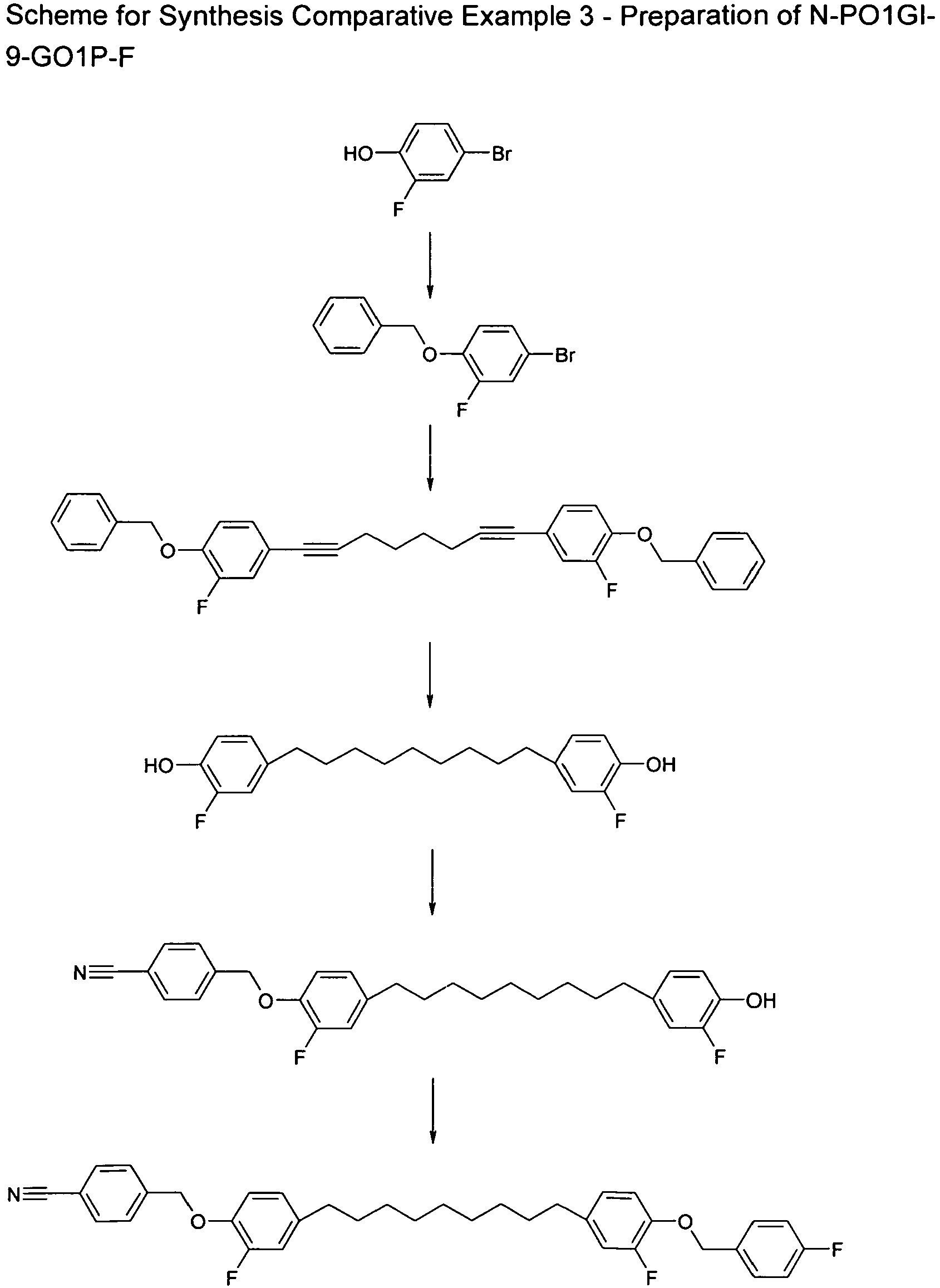
- Steps 3.1 to 3.3 are identical to those of Synthesis comparative example 2.
- The product of the synthesis example 2, step 2.3 (2.50 g, 7.18 mmol), 4-bromomethyl-benzonitrile (2.81 g, 14.4 mmol) and potassium carbonate (1.79 g, 19.9 mmol) are mixed together in ethylmethylketone (50 ml). The reaction mixture is heated under reflux at 80°C for 12 hours. The reaction-mixture is then cooled and the solid precipitate formed is filtered off under vacuum, the filter pad is washed with ether then the solution is concentrated under reduced pressure. The crude product is purified by chromatography through silica, eluted with 30 % DCM in petroleum ether (40-60). The material is then re-crystallised from acetonitrile to yield the desired non symmetrical intermediate alcohol.
- The product from the previous step, step 3.4 (2.15 g, 4.64 mmol), 1-bromomethyl-4-fluorobenzene (1.05 g, 5.56 mmol) and potassium carbonate (1.92 g, 14.0 mmol) are mixed together in ethylmethylketone (50 ml). The reaction mixture is heated under reflux at 80°C for 18 hours. The reaction-mixture is then cooled and solids filtered off under vacuum, the filter pad is washed with diethyl ether then concentrated under reduced pressure. The crude product is purified by chromatography through silica, eluted with 30% DCM in petroleum ether (40-60). The material was then re-crystallised twice from acetonitrile to afford the product.

- 25.0 g (88.4 mmol) of iodobromobenzene and 80 ml tetrahydrofuran are added to a reaction flask, which is evacuated three times and subsequently filled with nitrogen each time, then "ultasonicated" for 10 min. with additional evacuation/purging with nitrogen. Pd(PPh3)2Cl2 (0.9 g, 1.3 mmol) and CuI (0.2 g, 1.1 mmol) as catalysts and diisopropylamine (14 ml) are an ultrasonic bath for 10 minutes and then placed in a large water bath to control the reaction temperature.
- 1,8-nonadiyne (5:0 g, 41.6 mmol) is mixed with tetrahydrofuran (20 ml) and added slowly over a time span of 15 minutes. A fine precipitate is formed. The reaction mixture is stirred overnight at ambient temperature. The reaction mixture is then filtered under vacuum and the filter pad washed with tetrahydrofuran. The filtrate is concentrated to a semi-solid, which is re-dissolved in dichloromethane before being passed through a silica column for purification. The target product is eluted with additional dichloromethane to afford a yellow crystalline solid.
- The hydrogenation reaction is performed in an "H-Cube"-hydrogenation apparatus. The parameters of the reaction are as follows: Flow rate: 7 ml/min., Mode: 100 % H2, Catalysts: Pt/C, Temperature: 50°C, and Pressure: 30 bar.
- Anhydrous tetrahydrofuran is charged into a three neck flask together with 9.4 g (19.8 mmol) of the dibromide from the previous stage. The flask is evacuated and filled with nitrogen. The reaction mixture is stirred and cooled to a temperature of -75°C in a bath of acetone cooled by solid CO2.
- Then n-butyl lithium (1.6 M, 31 ml, 49.5 mmol) are added drop wise over a time span of 30 minutes while keeping the temperature at -75°C. After 3 hours further stirring 8.7 g (200 mmol) of crushed, solid CO2 are cautiously added to the reaction mixture. A thick white sludge develops and this is stirred for a further 30 minutes before it is hydrolysed by the addition of dilute HCl. The mixture is extracted three times with diethyl ether, and the combined organic material washed with water until neutral. Then toluene is added and the whole solvent is solution is evaporated. The solid the product is isolated and used in the following without further purification.
- The intermediate product from the previous stage (5.5 g,15 mmol) and propandithiol (3.6 g, 33 mmol) are added to flask before adding trifluoromethanesulphonic acid (6.8 g, 45 mmol) and starting to stir the mixture. The mixture is heated to 120°C and the now clear orange mixture is then cooled to ambient before being treated with diethyl ether (300 ml). The resultant solution is added to a flask of vigorously stirred diethyl ether (700 ml) pre-cooled to -70°C. Within 30 minutes fine crystals appear in the stirred mixture. The solid is isolated by filtration under vacuum and washed with ether to give a pale yellow powder which is used immediately.
- The intermediate (10.1g 12 mmol) from the previous stage is added to a flask with dichloromethane (50 ml) and then cooled to -70°C. A mixture of 4-cyanophenol (3.5 g, 30 mmol), dichloromethane (40 ml) and triethylamine (3.5 g, 34 mmol) is added dropwise. After 90 minutes further stirring triethylaminehydrogen fluoride (20 g, 125 mmol) is added dropwise. After a further hour of stirring bromine (19.9 g, 125 mmol) in dichloromethane (100 ml) is added dropwise. Th reaction mixture is stirred for 30 minutes and allowed to warm to -30°C before adding morpholine (10.9 g, 125 mmol) and finally warming to 0°C where it is stirred for a further time span of 1 hour. The mixture is carefully poured onto a mixture of ice, water and potassium hydroxide, and the layers are separated. The organic material is washed with water, dried over sodium sulphate and concentrated in vacuo. The crude material is purified by flash chromatography, eluting with a solution of 30 % DCM in petroleum ether. Final purification is carried out by repeated re-crystallisation from acetonitrile to afford the desired product.

- Steps 5.1 to 5.3 are identical to the respective steps of Synthesis Example 1.
- The intermediate product of Synthesis Example 1, step 1.3 (5.5 g,15 mmol) and propandithiol (3.6 g, 33 mmol) are added to flask before adding trifluoromethanesulphonic acid (6.8 g, 45 mmol) and starting to stir the mixture. The mixture is heated to 120°C and the then clear orange mixture is cooled to ambient before being treated with diethyl ether (300 ml). The resultant solution is added to a flask of vigorously stirred diethyl ether (700 ml) pre-cooled to -70°C. Within 30 minutes fine crystals appear in the stirred mixture. The solid is isolated by filtration under vacuum and washed with ether to give a pale yellow powder which is used immediately.
- The intermediate (10.1 g 12 mmol) from the previous step is added to a flask with dichloromethane (50 ml) and then cooled to -70°C. A mixture of 4-cyanophenol (3.5 g, 30 mmol), dichloromethane (40 ml) and triethylamine (3.5 g, 34 mmol) is added dropwise. After 90 minutes further stirring triethylaminehydrogen fluoride (20 g, 125 mmol) is added dropwise. After a further hour of stirring bromine (19.9 g, 125 mmol) in dichloromethane (100 ml) is added dropwise. The reaction mixture is stirred for 30 minutes and allowed to warm to -30°C before adding morpholine (10.9 g, 125 mmol) and finally warming to 0°C where it is stirred for a further time span of 1 hour. The mixture is carefully poured onto a mixture of ice, water and potassium hydroxide, and the layers are separated. The organic material is washed with water, dried over sodium sulphate and concentrated in vacuo. The crude material is purified by flash chromatography, eluting with a solution of 30 % DCM in petroleum ether. Final purification is carried out by repeated re-crystallisation from acetonitrile to afford the desired product.

-

- Methylbutylbiphenyl (44.8 g,0.2 mol), dichloromethane (250 ml), tetraethylammonium bromide (2.1 g, 10 mmol) and hydrogen bromide (51.6 g, 0.3 mol) are introduced into a reaction flask and cooled to 0°C. Hydrogen peroxide (48.6 g, 0.5 mol) is added with a dosage of 0.1 ml/min.. After the reaction is shown to have completed (by TLC analysis), the reaction is cooled to 0-10°C and sodium sulfite (17.8 g, 014 mol) as an aqueous solution is added until de-coloration occurs. Thereby, the temperature to is maintained at 10°C. The solution turns green. Then the reaction mixture is stirred for 2 hours. Subsequently a 10 % sodium carbonate solution is prepared and added. The resultant two phases are separated. The aqueous phase is extracted with 100 ml of dichloromethane and added to the organic phase.
- The material is washed with sodium carbonate solution and then water before being concentrated in vacuo.
The residue is then dissolved in 150 ml ethanol and heated for 3 hours under reflux. - The solution is drained and cooled in an ice bath. The resulting crystals are filtered off and dried under ambient atmosphere.
-

- To a stirred solution of the cyano biphenol (25.0 g, 128 mmol) in acetone (625 ml), potassium carbonate (37.5 g, 271 mmol) is added, heated under reflux for 1 hour under a nitrogen atmosphere, and then cooled to ambient temperature. Dibromononane (200 ml, 961 mmol) is then added in a single portion. The reaction mixture is heated again to reflux. After heating under reflux overnightthe reaction was cooled and filtered under vacuum, the filter pad washed with dcm, and the filtrate evaporated under reduced pressure to afford the crude material. This was vacuum distilled on Kugelrohr apparatus to remove excess dibromononane affording a solid pale yellow product.
-

- 4-methoxybenzoic acid (10 g, 65.7 mmol), intermediate from step 6.1 (15.7 g, 65.3 mmol), Dicyclohexylcarbodiimide (13.5 g, 65.4 mmol), Dimethylamino pyridine (0.5 g) and Dichloromethane (250 ml) are added to a flask under nitrogen atmosphere stirred at 30°C overnight. The progress of the reaction procedure is monitored by TLC. When the reaction appears complete, Oxalic acid (5.9 g, 65.7 mmol) is added, then the reaction mixture is filtered using vacuum and the filtrate evaporated to dryness in vacuo. The product is isolated as a white solid.
-
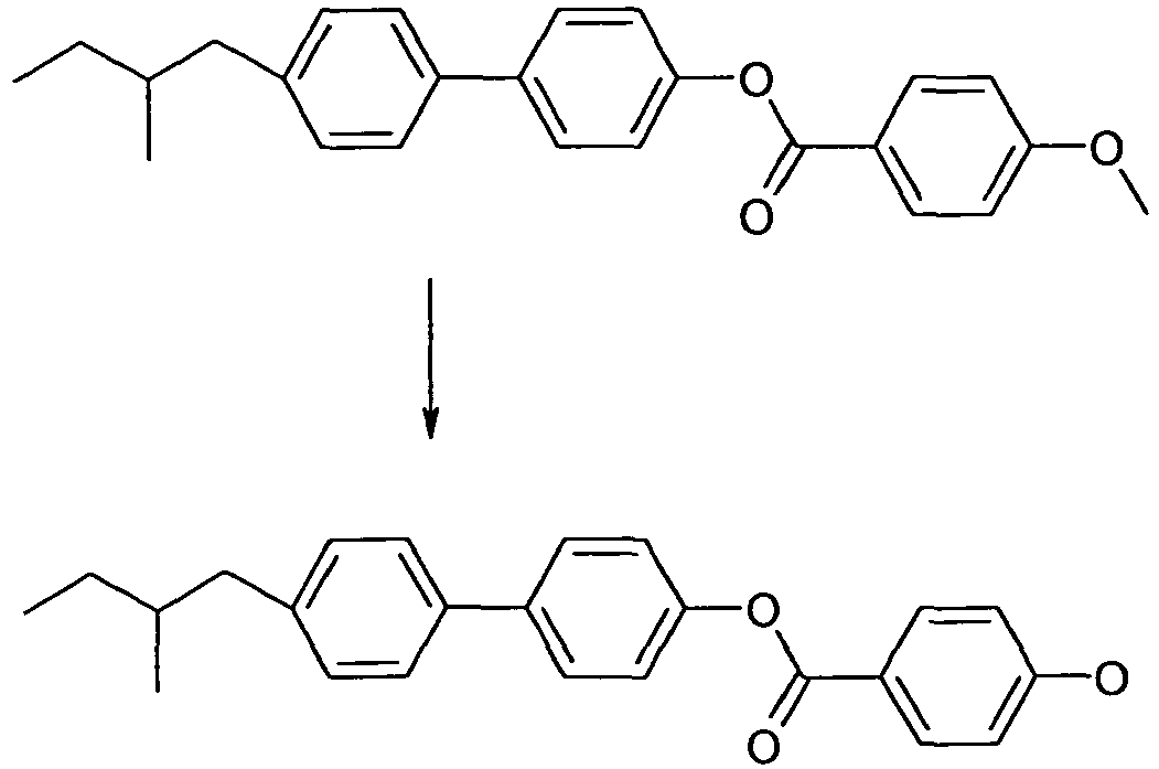
- The ester from step 6.3 (20 g, 53.4 mmol) is dissolved in Dichloromethane (80 ml) and added to a suspension of aluminium chloride (35 g, 262 mmol) in Dichloromethane (80 ml) at a temperature in the range from 0°C to - 5°C. Dimethyl sulphide (21 ml, 284 mmol)) is then added dropwise, while the temperature is maintained below 0°C and the resulting mixture (brown solution) is stirred overnight.
- The reaction is quenched by the addition (which is exothermic) of (saturated) ammonium chloride solution until the resultant mixture is acidic leading to a white solid precipitate, diluted with Dichloromethane and filtered off under vacuum collecting the precipitate.
-

- The intermediate from Step 6.4 (3.5 g, 9.71 mmol), the intermediate from step 5.2 (4.0 g, 9.9 mmol), potassium iodide (1.8 g, 10.9 mmol), potassium carbonate (0.9 g, 6.5 mmol) and dimethylformamide (100 ml) are added to a flask and heated at 100°C under reflux for 48 hours.
- The reaction is cooled, the reaction mixture poured into a mixture of dichloromethane and water, the layers are separated and the organic solution is washed with water, the organics are dried over sodium sulphate, filtered and concentrated in vacuo to yield a yellow solid.
- The material is purified by column chromatography, eluting with DCM with increasing amounts of Industrial methylated spirits. The product is recrystallized from acetone to give the final material.

Phase sequence: to be determined. - The following compounds of formula I are prepared analogously.


Phase sequence: K 108.7 (N2 60 N 86) I.
Phase sequence: K 118.6 N 135.8 I.


Phase sequence: K 85 I.
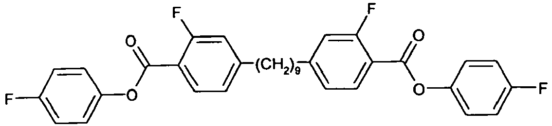


Phase sequence: K 69.9 I.


- The materials in the above table generally showed increased performance in the screening mixtures, as compared to known, more conventional bimesogenic compounds as e.g. those shown in the table below.
-

Phase sequence: K 109.8 I.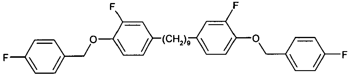
Phase sequence: K 77.5 I.
Phase sequence: K 84.1 SmC 105.7 N 122 I.
Phase sequence: to be determined. - The mixture M-1 shows an N to N2 transition at 35°C. This mixture (M-1) is well suitable for the USH-mode.
- The following mixture is prepared (Mixture C-1)
Composition Compound No. Abbreviation Conc. /% 1 R-5011 2.0 2 F-PGI-O-9-O-GP-F 22.0 3 F-PGI-O-9-O-PP-N 22.0 4 F-PGI-ZI-9-Z-GP-F 22.0 5 F-PGI-ZI-9-Z-PP-N 22.0 6 N-PP-9-PP-N 10.0 ∑ 100.0 - This mixture, mixture C-1, shows an N to N2 transition at 42°C. In mixture mixture M-1 the second nematic phase has a lower onset temperature and is allowed to exist at a lower temperature.
- The following mixture is prepared (Mixture M-2)
Composition Corroound No. Abbreviation Conc. /% 1 R-5011 2.0 2 F-PGI-O-9-O-GP-F 22.0 3 F-PGI-O-9-O-PP-N 22.0 4 F-PGI-ZI-9-Z-GP-F 22.0 5 F-PGI-ZI-9-Z-PP-N 22.0 6 N-GIZIP-7-PZG-N 10.0 ∑ 100.0 - This mixture, mixture M-2, shows an N to N2 transition at 31°C. This mixture (M-2) is well suitable for the USH-mode.
- The following mixture is prepared (Mixture C-2)
Composition Compound No. Abbreviation Conc. /% 1 R-5011 2.0 2 F-PGI-O-9-O-GP-F 22.0 3 F-PGI-O-9-O-PP-N 22.0 4 F-PGI-ZI-9-Z-GP-F 22.0 5 F-PGI-ZI-9-Z-PP-N 22.0 6 N-GIGI-9-GG-N 10.0 ∑ 100.0 - This mixture, mixture C-2, shows an N to N2 transition at 32°C. Also here In mixture M-2 the second nematic phase has a lower onset temperature and is allowed to exist at a lower temperature.
wherein
at least one of


Claims (15)
- Bimesogenic compounds of formula I
 R11 and R12 are each independently H, F, Cl, CN, NCS or a straight-chain or branched alkyl group with 1 to 25 C atoms which may be unsubstituted, mono- or polysubstituted by halogen or CN, it being also possible for one or more non-adjacent CH2 groups to be replaced, in each occurrence independently from one another, by -O-, -S-, -NH-, -N(CH3)-, -CO-, -COO-, -OCO-, -O-CO-O-, -S-CO-, -CO-S-, -CH=CH-, -CH=CF-, -CF=CF- or -C≡C- in such a manner that oxygen atoms are not linked directly to one another,MG11 and MG12 are each independently a mesogenic group and at least one ofMG11 and MG12 comprises two or more 6-atomic rings, at least two of which are linked by a 2-atomic linking group, selected from -CO-O- and -O-CO-, andSp1 is a spacer group comprising 1, 3 or 5 to 40 C atoms, wherein one or more non-adjacent and non-terminal CH2 groups may also be replaced by -O-, -S-, -NH-, -N(CH3)-, -CO-, -O-CO-, -S-CO-, -O-COO-, -CO-S-, -CO-O-, -CH(halogen)-, -CH(CN)-, -CH=CH- or -C≡C-, however in such a way that no two O-atoms are adjacent to one another, no two -CH=CH- groups are adjacent to each other and no two groups selected from-O-CO-, -S-CO-, -O-COO-, -CO-S-, -CO-O- and -CH=CH- are adjacent to each other,X11 and X12 are independently from one another a linking group selected from -CO-O-, -O-CO-, -CH=CH-, -C≡C-, -S-, -O-and a single bond,however under the condition that in -X11-Sp1-X12- no two O atoms are adjacent to one another, now two -CH=CH- groups are adjacent to each other and no two groups selected from -O-CO-, -S-CO-, -O-COO-, -CO-S-, -CO-O- and -CH=CH- are adjacent to each other.
 - Bimesogenic compounds according to claim 1, characterized in that MG11 and MG12 are independently of each other selected of partial formula II
-A11-(Z11-A12)k- II
wherein
at least one ofZ11, which is present, is -COO- or -OCO-,and the others present are, independently of those defined above and of each other, -COO-, -OCO-, -O-CO-O-, -OCH2-, -CH2O-, -OCF2-, -CF2O-, -CH2CH2-, -(CH2)4-, -CF2CF2-, -CH=CH-, -CF=CF-, -CH=CH-COO-, -OCO-CH=CH- or -C≡C-, optionally substituted with one or more of F, S or are a single bond,A11 and A12 are each independently in each occurrence 1,4-phenylene, wherein in addition one or more CH groups may be replaced by N, trans-1,4-cyclo-hexylene in which, in addition, one or two non-adjacent CH2 groups may be replaced by O and/or S, 1,4-cyclohexenylene, 1,4-bicyclo-(2,2,2)-octylene, piperidine-1,4-diyl, naphthalene-2,6-diyl, decahydro-naphthalene-2,6-diyl, 1,2,3,4-tetrahydro-naphthalene-2,6-diyl, cyclobutane-1,3-diyl, spiro[3.3]heptane-2,6-diyl or dispiro[3.1.3.1] decane-2,8-diyl, it being possible for all these groups to be unsubstituted, mono-, di-, tri- or tetrasubstituted with F, Cl, CN or alkyl, alkoxy, alkylcarbonyl or alkoxycarbonyl groups with 1 to 7 C atoms, wherein one or more H atoms may be substituted by F or Cl, andk is 1, 2, 3 or 4. - Bimesogenic compounds according to claim 1 or 2, characterized in that MG11 and MG12 are independently of one another selected from the group of formulae II-1 to II-26
-Phe-Z-Phe- II-1 -Phe-Z-Cyc- II-2 -Cyc-Z-Cyc- II-3 -Phe-Z-PheL- II-4 -PheL-Z-Phe- II-5 -PheL-Z-Cyc- II-6 -PheL-Z-PheL- II-7 -Phe-Z-Phe-Z-Phe- II-8 -Phe-Z-Phe-Z-Cyc- II-9 -Phe-Z-Cyc-Z-Phe- II-10 -Cyc-Z-Phe-Z-Cyc- II-11 -Phe-Z-Cyc-Z-Cyc- II-12 -Cyc-Z-Cyc-Z-Cyc- II-13 -Phe-Z-Phe-Z-PheL- II-14 -Phe-Z-PheL-Z-Phe- II-15 -PheL-Z-Phe-Z-Phe- II-16 -PheL-Z-Phe-Z-PheL- II-17 -PheL-Z-PheL-Z-Phe- II-18 -PheL-Z-PheL-Z-PheL- II-19 -Phe-Z-PheL-Z-Cyc- II-20 -Phe-Z-Cyc-Z-PheL- II-21 -Cyc-Z-Phe-Z-PheL- II-22 -PheL-Z-Cyc-Z-PheL- II-23 -PheL-Z-PheL-Z-Cyc- II-24 -PheL-Z-Cyc-Z-Cyc- II-25 -Cyc-Z-PheL-Z-Cyc- II-26 Cyc is 1,4-cyclohexlene, preferably trans-1,4-cyclohexlene,Phe is 1,4-phenylene,PheL is 1,4-phenylene, which is substituted by one, two or three fluorine atoms, by one or two Cl atoms or by one Cl atom and one F atom, andat least one ofZ, which is present, is -COO- or -OCO-. - Bimesogenic compounds according to at least one of claims 1 to 3, characterized in that at MG11 and MG12 are independently of one another selected from the group of formulae IIa to IIf

IIa 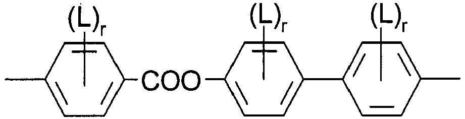
IIb 
IIc 
IId 
IIe 
IIf L is in each occurrence independently of each other F or Cl andr is in each occurrence independently of each other 0, 1, 2 or 3. - Bimesogenic compounds according to claim 4, characterized in thatr is in each occurrence independently of each other 0, 1 or 2.
- Bimesogenic compounds according to claim 4 or 5, characterized in that the group


- Bimesogenic compounds according to at least one of claims 4 to 6, characterized in thatL is in each occurrence F.
- Bimesogenic compounds according to at least one of claims 1 to 7, characterized in that R11 and R12 are selected from F, Cl and CN.
- Bimesogenic compounds according to at least one of claims 1 to 8, characterized in that Sp1 is -(CH2)o- and o is 1, 3 or an integer from 5 to 15.
- Use of one or more bimesogenic compounds according to at least one of claims 1 to 9 in a liquid crystalline medium.
- Liquid-crystalline medium, characterised in that it comprises one or more bimesogenic compounds according to at least one or more of claims 1 to 10.
- Liquid-crystalline medium according to claim 11, characterised in that it additionally comprises one or more compounds selected from the group of the compounds of the formulae III
R31-MG31-X31-Sp3-X32-MG32-R32 III
whereinR31and R32 are each independently H, F, Cl, CN, NCS or a straight-chain or branched alkyl group with 1 to 25 C atoms which may be unsubstituted, mono- or polysubstituted by halogen or CN, it being also possible for one or more non-adjacent CH2 groups to be replaced, in each case independently from one another, by -O-, -S-, -NH-, -N(CH3)-, -CO-, -COO-, -OCO-, -O-CO-O-, -S-CO-, -CO-S-, -CH=CH-, -CH=CF-, -CF=CF- or -C≡C- in such a manner that oxygen atoms are not linked directly to one another,MG31 and MG32 are each independently a mesogenic group,Sp3 is a spacer group comprising 5 to 40 C atoms, wherein one or more non-adjacent CH2 groups may also be replaced by -O-, -S-, -NH-, -N(CH3)-, -CO-, -O-CO-, -S-CO-, -O-COO-, -CO-S-, -CO-O-, -CH(halogen)-, -CH(CN)-, -CH=CH- or -C≡C-, andX31 and X32 are each independently -O-, -S-, -CO-, -COO-, -OCO-, -O-CO-O-, -CO-NH-, -NH-CO-, -CH2CH2-, -OCH2-, -CH2O-, -SCH2-, -CH2S-, -CH=CH-, -CH=CH-COO-, -OCO-CH=CH-, -C≡C- or a single bond, andwith the condition that compounds of formula I are excluded. - Use of a liquid crystal medium according to claim 11 or 12, in a liquid crystal device.
- Liquid crystal device comprising a liquid crystalline medium comprising two or more components, one or more of which is a bimesogenic compound of formula I according at least one of claims 1 to 9.
- Liquid crystal device according to claim 14, characterized in that it is a flexoelectric device.
Priority Applications (1)
| Application Number | Priority Date | Filing Date | Title |
|---|---|---|---|
| EP13727515.2A EP2855627B1 (en) | 2012-05-25 | 2013-05-07 | Bimesogenic compounds and mesogenic media |
Applications Claiming Priority (3)
| Application Number | Priority Date | Filing Date | Title |
|---|---|---|---|
| EP12004081 | 2012-05-25 | ||
| PCT/EP2013/001353 WO2013174478A1 (en) | 2012-05-25 | 2013-05-07 | Bimesogenic compounds and mesogenic media |
| EP13727515.2A EP2855627B1 (en) | 2012-05-25 | 2013-05-07 | Bimesogenic compounds and mesogenic media |
Publications (2)
| Publication Number | Publication Date |
|---|---|
| EP2855627A1 EP2855627A1 (en) | 2015-04-08 |
| EP2855627B1 true EP2855627B1 (en) | 2017-09-20 |
Family
ID=48577675
Family Applications (1)
| Application Number | Title | Priority Date | Filing Date |
|---|---|---|---|
| EP13727515.2A Not-in-force EP2855627B1 (en) | 2012-05-25 | 2013-05-07 | Bimesogenic compounds and mesogenic media |
Country Status (7)
| Country | Link |
|---|---|
| US (1) | US20150090935A1 (en) |
| EP (1) | EP2855627B1 (en) |
| JP (1) | JP6600255B2 (en) |
| KR (1) | KR20150013898A (en) |
| CN (1) | CN104364347B (en) |
| TW (1) | TWI630262B (en) |
| WO (1) | WO2013174478A1 (en) |
Families Citing this family (31)
| Publication number | Priority date | Publication date | Assignee | Title |
|---|---|---|---|---|
| EP2855631B1 (en) * | 2012-05-25 | 2017-09-20 | Merck Patent GmbH | Mesogenic media and liquid crystal display |
| KR20150036406A (en) * | 2012-07-06 | 2015-04-07 | 메르크 파텐트 게엠베하 | Bimesogenic compounds and mesogenic media |
| KR20150036405A (en) * | 2012-07-06 | 2015-04-07 | 메르크 파텐트 게엠베하 | Bimesogenic compounds and mesogenic media |
| WO2014032772A1 (en) * | 2012-08-29 | 2014-03-06 | Merck Patent Gmbh | Bimesogenic compounds and mesogenic media |
| KR20160088425A (en) * | 2013-11-22 | 2016-07-25 | 메르크 파텐트 게엠베하 | Mesogenic media and liquid crystal display |
| EP3071668B1 (en) * | 2013-11-22 | 2018-07-18 | Merck Patent GmbH | Bimesogenic compounds and mesogenic media |
| CN105849229B (en) * | 2013-12-23 | 2019-01-04 | 默克专利股份有限公司 | Double mesogenic compounds and mesogenic media |
| US9932381B2 (en) | 2014-06-18 | 2018-04-03 | Sanofi | Exendin-4 derivatives as selective glucagon receptor agonists |
| US10450508B2 (en) * | 2014-07-17 | 2019-10-22 | Merck Patent Gmbh | Bimesogenic compounds and mesogenic media |
| CN104087311B (en) * | 2014-07-21 | 2015-12-30 | 西安近代化学研究所 | A kind of two mesomorphic unit liquid crystalline cpd |
| CN105487157A (en) * | 2014-08-13 | 2016-04-13 | 南京晶多新材料科技有限公司 | Construction and application of electric control light modulation film serving as scattering polaroid |
| KR20170078834A (en) * | 2014-11-06 | 2017-07-07 | 메르크 파텐트 게엠베하 | Light modulation element |
| EP3218446B1 (en) * | 2014-11-11 | 2018-07-04 | Merck Patent GmbH | Bimesogenic compounds and mesogenic media |
| US20180022996A1 (en) * | 2014-12-17 | 2018-01-25 | Merck Patent Gmbh | Bimesogenic compounds and mesogenic media |
| JP2018501514A (en) * | 2014-12-19 | 2018-01-18 | メルク パテント ゲゼルシャフト ミット ベシュレンクテル ハフツングMerck Patent Gesellschaft mit beschraenkter Haftung | Light modulation element |
| CN106281355B (en) * | 2015-06-04 | 2019-02-15 | 江苏和成显示科技有限公司 | Liquid crystal media and its application |
| CN106281360B (en) * | 2015-06-04 | 2019-02-15 | 江苏和成显示科技有限公司 | Liquid-crystal composition and its application |
| CN106281359B (en) * | 2015-06-04 | 2019-02-15 | 江苏和成显示科技有限公司 | Liquid-crystal composition and its display device |
| EP3365411B1 (en) * | 2015-10-23 | 2020-05-13 | Merck Patent GmbH | Light modulation element |
| EP3383970B1 (en) * | 2015-12-02 | 2021-03-31 | Merck Patent GmbH | Liquid crystal medium and liquid crystal device |
| CN105549290B (en) * | 2016-02-01 | 2019-07-23 | 京东方科技集团股份有限公司 | Display panels and display devices |
| JP2019533037A (en) | 2016-09-14 | 2019-11-14 | メルク パテント ゲゼルシャフト ミット ベシュレンクテル ハフツングMerck Patent Gesellschaft mit beschraenkter Haftung | Liquid crystal medium and liquid crystal device |
| WO2018104279A1 (en) | 2016-12-08 | 2018-06-14 | Merck Patent Gmbh | Liquid crystal medium and liquid crystal device |
| US11434426B2 (en) | 2017-03-13 | 2022-09-06 | Kent State University | Fast flexoelectro-optic switching based on bimesogen-doped and polymer-stabilized vertical standing helix mode |
| WO2019030153A1 (en) | 2017-08-08 | 2019-02-14 | Merck Patent Gmbh | Liquid crystal medium and liquid crystal device |
| CN111032825A (en) | 2017-08-08 | 2020-04-17 | 默克专利股份有限公司 | Liquid crystal medium and liquid crystal device |
| CN111263799A (en) | 2017-10-25 | 2020-06-09 | 默克专利股份有限公司 | Liquid crystal medium and liquid crystal device |
| WO2019081389A1 (en) | 2017-10-25 | 2019-05-02 | Merck Patent Gmbh | Liquid crystal medium and liquid crystal device |
| GB2583649A (en) | 2017-12-18 | 2020-11-04 | Merck Patent Gmbh | Liquid crystal compound and liquid crystal medium |
| WO2019179962A1 (en) | 2018-03-22 | 2019-09-26 | Merck Patent Gmbh | Liquid-crystalline medium |
| CN111983867A (en) * | 2019-05-24 | 2020-11-24 | 江苏集萃智能液晶科技有限公司 | Bistable light modulator |
Family Cites Families (23)
| Publication number | Priority date | Publication date | Assignee | Title |
|---|---|---|---|---|
| JPS6322865A (en) * | 1986-04-11 | 1988-01-30 | ザ・ボ−ド オブ トラスティ−ズ オブ ザ ユニヴァ−シティ オブ イリノイ | Polymer improved in electric and magnetic characteristics |
| DE4000451B4 (en) | 1990-01-09 | 2004-12-09 | Merck Patent Gmbh | Electro-optical liquid crystal switching element |
| JP3075807B2 (en) * | 1991-10-14 | 2000-08-14 | 汪芳 白井 | Liquid crystal material |
| EP0588568B1 (en) | 1992-09-18 | 2002-12-18 | Hitachi, Ltd. | A liquid crystal display device |
| JPH08295645A (en) * | 1995-04-28 | 1996-11-12 | Nippon Oil & Fats Co Ltd | Liquid crystal compound |
| JP3692430B2 (en) * | 1995-06-28 | 2005-09-07 | 大日本インキ化学工業株式会社 | 4- (2-Cyclohexylpropyl) benzene derivative |
| WO1998000428A1 (en) | 1996-07-01 | 1998-01-08 | Merck Patent Gmbh | Chiral dopants |
| DE19649056A1 (en) * | 1996-11-27 | 1998-05-28 | Basf Ag | Polymerizable oligomesogens |
| JPH10237002A (en) * | 1997-02-26 | 1998-09-08 | Japan Energy Corp | Novel asymmetric twin compound and liquid crystal composition containing the same |
| DE19834162A1 (en) * | 1997-08-13 | 1999-02-18 | Merck Patent Gmbh | Chiral connections |
| EP0971016B1 (en) | 1998-07-08 | 2003-05-21 | MERCK PATENT GmbH | Mesogenic estradiols |
| GB2356629B (en) * | 1999-10-04 | 2004-09-22 | Merck Patent Gmbh | Bimesogenic Compounds and Flexoelectric Devices |
| JP2002128743A (en) * | 2000-10-19 | 2002-05-09 | Dainippon Ink & Chem Inc | Polymerizable liquid crystal compound |
| JP4766291B2 (en) * | 2001-06-27 | 2011-09-07 | Dic株式会社 | Polymerizable liquid crystal compound, composition, and optical anisotropic body |
| GB0225662D0 (en) * | 2001-11-16 | 2002-12-11 | Merck Patent Gmbh | Liquid crystalline medium and liquid crystal display |
| ATE314446T1 (en) * | 2002-10-08 | 2006-01-15 | Merck Patent Gmbh | LIQUID CRYSTAL MEDIUM AND LIQUID CRYSTAL DISPLAY |
| US7125951B2 (en) * | 2002-10-24 | 2006-10-24 | South Dakota School Of Mines And Technology | Monomers containing at least one biaryl unit and polymers and derivatives prepared therefrom |
| JP4342170B2 (en) * | 2002-12-17 | 2009-10-14 | 三井化学株式会社 | Liquid crystal composition and liquid crystal element |
| JP4246145B2 (en) * | 2003-12-18 | 2009-04-02 | シャープ株式会社 | Display element and display device |
| GB0402006D0 (en) * | 2004-01-30 | 2004-03-03 | Dow Corning Ltd | Liquid crystal materials |
| JP2008525331A (en) * | 2004-12-23 | 2008-07-17 | メルク パテント ゲゼルシャフト ミット ベシュレンクテル ハフトング | Bimesogenic compounds and flexoelectric devices |
| JP5496660B2 (en) * | 2006-06-09 | 2014-05-21 | メルク パテント ゲゼルシャフト ミット ベシュレンクテル ハフツング | Liquid crystal medium and liquid crystal display |
| KR101106528B1 (en) * | 2009-06-30 | 2012-01-20 | 금오공과대학교 산학협력단 | Liquid crystal compound having this mesogen structure |
-
2013
- 2013-05-07 WO PCT/EP2013/001353 patent/WO2013174478A1/en not_active Ceased
- 2013-05-07 KR KR1020147036288A patent/KR20150013898A/en not_active Ceased
- 2013-05-07 CN CN201380026565.0A patent/CN104364347B/en active Active
- 2013-05-07 US US14/403,201 patent/US20150090935A1/en not_active Abandoned
- 2013-05-07 EP EP13727515.2A patent/EP2855627B1/en not_active Not-in-force
- 2013-05-07 JP JP2015513036A patent/JP6600255B2/en not_active Expired - Fee Related
- 2013-05-24 TW TW102118499A patent/TWI630262B/en not_active IP Right Cessation
Non-Patent Citations (1)
| Title |
|---|
| None * |
Also Published As
| Publication number | Publication date |
|---|---|
| WO2013174478A1 (en) | 2013-11-28 |
| TWI630262B (en) | 2018-07-21 |
| CN104364347B (en) | 2017-12-01 |
| EP2855627A1 (en) | 2015-04-08 |
| US20150090935A1 (en) | 2015-04-02 |
| KR20150013898A (en) | 2015-02-05 |
| TW201404870A (en) | 2014-02-01 |
| CN104364347A (en) | 2015-02-18 |
| JP2015523334A (en) | 2015-08-13 |
| JP6600255B2 (en) | 2019-10-30 |
Similar Documents
| Publication | Publication Date | Title |
|---|---|---|
| EP2855631B1 (en) | Mesogenic media and liquid crystal display | |
| EP2729549B1 (en) | Bimesogenic compounds | |
| EP3071669B1 (en) | Mesogenic media and liquid crystal display device | |
| EP2870217B1 (en) | Bimesogenic compounds and mesogenic media | |
| EP2870219B1 (en) | Bimesogenic compounds and mesogenic media | |
| EP2870218B1 (en) | Bimesogenic compounds and mesogenic media | |
| EP3218446B1 (en) | Bimesogenic compounds and mesogenic media | |
| EP2890762B1 (en) | Bimesogenic compounds and mesogenic media | |
| EP2855627A1 (en) | Bimesogenic compounds and mesogenic media | |
| EP3044288B1 (en) | Mesogenic compounds and mesogenic media | |
| EP2928985B1 (en) | Bimesogenic compounds and mesogenic media | |
| EP3169749B1 (en) | Bimesogenic compounds and mesogenic media | |
| EP3240859B1 (en) | Bimesogenic compounds and mesogenic media | |
| EP3071668B1 (en) | Bimesogenic compounds and mesogenic media | |
| EP3234064B1 (en) | Bimesogenic compounds and mesogenic media | |
| EP3087157B1 (en) | Bimesogenic compounds and mesogenic media | |
| EP3234067B1 (en) | Bimesogenic compounds and mesogenic media | |
| EP3234065B1 (en) | Bimesogenic compounds and mesogenic media | |
| EP3049506B1 (en) | Compounds and mesogenic media |
Legal Events
| Date | Code | Title | Description |
|---|---|---|---|
| PUAI | Public reference made under article 153(3) epc to a published international application that has entered the european phase |
Free format text: ORIGINAL CODE: 0009012 |
|
| 17P | Request for examination filed |
Effective date: 20141007 |
|
| AK | Designated contracting states |
Kind code of ref document: A1 Designated state(s): AL AT BE BG CH CY CZ DE DK EE ES FI FR GB GR HR HU IE IS IT LI LT LU LV MC MK MT NL NO PL PT RO RS SE SI SK SM TR |
|
| AX | Request for extension of the european patent |
Extension state: BA ME |
|
| DAX | Request for extension of the european patent (deleted) | ||
| 17Q | First examination report despatched |
Effective date: 20160916 |
|
| GRAP | Despatch of communication of intention to grant a patent |
Free format text: ORIGINAL CODE: EPIDOSNIGR1 |
|
| RIC1 | Information provided on ipc code assigned before grant |
Ipc: C09K 19/02 20060101AFI20170407BHEP Ipc: C09K 19/58 20060101ALI20170407BHEP Ipc: C09K 19/04 20060101ALI20170407BHEP |
|
| INTG | Intention to grant announced |
Effective date: 20170428 |
|
| GRAS | Grant fee paid |
Free format text: ORIGINAL CODE: EPIDOSNIGR3 |
|
| GRAA | (expected) grant |
Free format text: ORIGINAL CODE: 0009210 |
|
| AK | Designated contracting states |
Kind code of ref document: B1 Designated state(s): AL AT BE BG CH CY CZ DE DK EE ES FI FR GB GR HR HU IE IS IT LI LT LU LV MC MK MT NL NO PL PT RO RS SE SI SK SM TR |
|
| REG | Reference to a national code |
Ref country code: GB Ref legal event code: FG4D |
|
| REG | Reference to a national code |
Ref country code: CH Ref legal event code: EP |
|
| REG | Reference to a national code |
Ref country code: AT Ref legal event code: REF Ref document number: 930116 Country of ref document: AT Kind code of ref document: T Effective date: 20171015 |
|
| REG | Reference to a national code |
Ref country code: IE Ref legal event code: FG4D |
|
| REG | Reference to a national code |
Ref country code: DE Ref legal event code: R096 Ref document number: 602013026837 Country of ref document: DE |
|
| REG | Reference to a national code |
Ref country code: NL Ref legal event code: MP Effective date: 20170920 |
|
| PG25 | Lapsed in a contracting state [announced via postgrant information from national office to epo] |
Ref country code: HR Free format text: LAPSE BECAUSE OF FAILURE TO SUBMIT A TRANSLATION OF THE DESCRIPTION OR TO PAY THE FEE WITHIN THE PRESCRIBED TIME-LIMIT Effective date: 20170920 Ref country code: FI Free format text: LAPSE BECAUSE OF FAILURE TO SUBMIT A TRANSLATION OF THE DESCRIPTION OR TO PAY THE FEE WITHIN THE PRESCRIBED TIME-LIMIT Effective date: 20170920 Ref country code: LT Free format text: LAPSE BECAUSE OF FAILURE TO SUBMIT A TRANSLATION OF THE DESCRIPTION OR TO PAY THE FEE WITHIN THE PRESCRIBED TIME-LIMIT Effective date: 20170920 Ref country code: SE Free format text: LAPSE BECAUSE OF FAILURE TO SUBMIT A TRANSLATION OF THE DESCRIPTION OR TO PAY THE FEE WITHIN THE PRESCRIBED TIME-LIMIT Effective date: 20170920 Ref country code: NO Free format text: LAPSE BECAUSE OF FAILURE TO SUBMIT A TRANSLATION OF THE DESCRIPTION OR TO PAY THE FEE WITHIN THE PRESCRIBED TIME-LIMIT Effective date: 20171220 |
|
| REG | Reference to a national code |
Ref country code: LT Ref legal event code: MG4D |
|
| REG | Reference to a national code |
Ref country code: AT Ref legal event code: MK05 Ref document number: 930116 Country of ref document: AT Kind code of ref document: T Effective date: 20170920 |
|
| PG25 | Lapsed in a contracting state [announced via postgrant information from national office to epo] |
Ref country code: LV Free format text: LAPSE BECAUSE OF FAILURE TO SUBMIT A TRANSLATION OF THE DESCRIPTION OR TO PAY THE FEE WITHIN THE PRESCRIBED TIME-LIMIT Effective date: 20170920 Ref country code: GR Free format text: LAPSE BECAUSE OF FAILURE TO SUBMIT A TRANSLATION OF THE DESCRIPTION OR TO PAY THE FEE WITHIN THE PRESCRIBED TIME-LIMIT Effective date: 20171221 Ref country code: BG Free format text: LAPSE BECAUSE OF FAILURE TO SUBMIT A TRANSLATION OF THE DESCRIPTION OR TO PAY THE FEE WITHIN THE PRESCRIBED TIME-LIMIT Effective date: 20171220 Ref country code: RS Free format text: LAPSE BECAUSE OF FAILURE TO SUBMIT A TRANSLATION OF THE DESCRIPTION OR TO PAY THE FEE WITHIN THE PRESCRIBED TIME-LIMIT Effective date: 20170920 |
|
| PG25 | Lapsed in a contracting state [announced via postgrant information from national office to epo] |
Ref country code: NL Free format text: LAPSE BECAUSE OF FAILURE TO SUBMIT A TRANSLATION OF THE DESCRIPTION OR TO PAY THE FEE WITHIN THE PRESCRIBED TIME-LIMIT Effective date: 20170920 |
|
| PG25 | Lapsed in a contracting state [announced via postgrant information from national office to epo] |
Ref country code: RO Free format text: LAPSE BECAUSE OF FAILURE TO SUBMIT A TRANSLATION OF THE DESCRIPTION OR TO PAY THE FEE WITHIN THE PRESCRIBED TIME-LIMIT Effective date: 20170920 Ref country code: CZ Free format text: LAPSE BECAUSE OF FAILURE TO SUBMIT A TRANSLATION OF THE DESCRIPTION OR TO PAY THE FEE WITHIN THE PRESCRIBED TIME-LIMIT Effective date: 20170920 Ref country code: PL Free format text: LAPSE BECAUSE OF FAILURE TO SUBMIT A TRANSLATION OF THE DESCRIPTION OR TO PAY THE FEE WITHIN THE PRESCRIBED TIME-LIMIT Effective date: 20170920 Ref country code: ES Free format text: LAPSE BECAUSE OF FAILURE TO SUBMIT A TRANSLATION OF THE DESCRIPTION OR TO PAY THE FEE WITHIN THE PRESCRIBED TIME-LIMIT Effective date: 20170920 |
|
| PG25 | Lapsed in a contracting state [announced via postgrant information from national office to epo] |
Ref country code: SM Free format text: LAPSE BECAUSE OF FAILURE TO SUBMIT A TRANSLATION OF THE DESCRIPTION OR TO PAY THE FEE WITHIN THE PRESCRIBED TIME-LIMIT Effective date: 20170920 Ref country code: AT Free format text: LAPSE BECAUSE OF FAILURE TO SUBMIT A TRANSLATION OF THE DESCRIPTION OR TO PAY THE FEE WITHIN THE PRESCRIBED TIME-LIMIT Effective date: 20170920 Ref country code: EE Free format text: LAPSE BECAUSE OF FAILURE TO SUBMIT A TRANSLATION OF THE DESCRIPTION OR TO PAY THE FEE WITHIN THE PRESCRIBED TIME-LIMIT Effective date: 20170920 Ref country code: SK Free format text: LAPSE BECAUSE OF FAILURE TO SUBMIT A TRANSLATION OF THE DESCRIPTION OR TO PAY THE FEE WITHIN THE PRESCRIBED TIME-LIMIT Effective date: 20170920 Ref country code: IS Free format text: LAPSE BECAUSE OF FAILURE TO SUBMIT A TRANSLATION OF THE DESCRIPTION OR TO PAY THE FEE WITHIN THE PRESCRIBED TIME-LIMIT Effective date: 20180120 Ref country code: IT Free format text: LAPSE BECAUSE OF FAILURE TO SUBMIT A TRANSLATION OF THE DESCRIPTION OR TO PAY THE FEE WITHIN THE PRESCRIBED TIME-LIMIT Effective date: 20170920 |
|
| REG | Reference to a national code |
Ref country code: DE Ref legal event code: R097 Ref document number: 602013026837 Country of ref document: DE |
|
| PLBE | No opposition filed within time limit |
Free format text: ORIGINAL CODE: 0009261 |
|
| STAA | Information on the status of an ep patent application or granted ep patent |
Free format text: STATUS: NO OPPOSITION FILED WITHIN TIME LIMIT |
|
| PG25 | Lapsed in a contracting state [announced via postgrant information from national office to epo] |
Ref country code: DK Free format text: LAPSE BECAUSE OF FAILURE TO SUBMIT A TRANSLATION OF THE DESCRIPTION OR TO PAY THE FEE WITHIN THE PRESCRIBED TIME-LIMIT Effective date: 20170920 |
|
| 26N | No opposition filed |
Effective date: 20180621 |
|
| PG25 | Lapsed in a contracting state [announced via postgrant information from national office to epo] |
Ref country code: SI Free format text: LAPSE BECAUSE OF FAILURE TO SUBMIT A TRANSLATION OF THE DESCRIPTION OR TO PAY THE FEE WITHIN THE PRESCRIBED TIME-LIMIT Effective date: 20170920 |
|
| REG | Reference to a national code |
Ref country code: CH Ref legal event code: PL |
|
| REG | Reference to a national code |
Ref country code: BE Ref legal event code: MM Effective date: 20180531 |
|
| PG25 | Lapsed in a contracting state [announced via postgrant information from national office to epo] |
Ref country code: MC Free format text: LAPSE BECAUSE OF FAILURE TO SUBMIT A TRANSLATION OF THE DESCRIPTION OR TO PAY THE FEE WITHIN THE PRESCRIBED TIME-LIMIT Effective date: 20170920 |
|
| REG | Reference to a national code |
Ref country code: IE Ref legal event code: MM4A |
|
| PG25 | Lapsed in a contracting state [announced via postgrant information from national office to epo] |
Ref country code: LI Free format text: LAPSE BECAUSE OF NON-PAYMENT OF DUE FEES Effective date: 20180531 Ref country code: CH Free format text: LAPSE BECAUSE OF NON-PAYMENT OF DUE FEES Effective date: 20180531 |
|
| PG25 | Lapsed in a contracting state [announced via postgrant information from national office to epo] |
Ref country code: LU Free format text: LAPSE BECAUSE OF NON-PAYMENT OF DUE FEES Effective date: 20180507 |
|
| PG25 | Lapsed in a contracting state [announced via postgrant information from national office to epo] |
Ref country code: FR Free format text: LAPSE BECAUSE OF NON-PAYMENT OF DUE FEES Effective date: 20180531 Ref country code: IE Free format text: LAPSE BECAUSE OF NON-PAYMENT OF DUE FEES Effective date: 20180507 |
|
| PG25 | Lapsed in a contracting state [announced via postgrant information from national office to epo] |
Ref country code: BE Free format text: LAPSE BECAUSE OF NON-PAYMENT OF DUE FEES Effective date: 20180531 |
|
| PGFP | Annual fee paid to national office [announced via postgrant information from national office to epo] |
Ref country code: GB Payment date: 20190501 Year of fee payment: 7 |
|
| PG25 | Lapsed in a contracting state [announced via postgrant information from national office to epo] |
Ref country code: MT Free format text: LAPSE BECAUSE OF NON-PAYMENT OF DUE FEES Effective date: 20180507 |
|
| PG25 | Lapsed in a contracting state [announced via postgrant information from national office to epo] |
Ref country code: TR Free format text: LAPSE BECAUSE OF FAILURE TO SUBMIT A TRANSLATION OF THE DESCRIPTION OR TO PAY THE FEE WITHIN THE PRESCRIBED TIME-LIMIT Effective date: 20170920 |
|
| PG25 | Lapsed in a contracting state [announced via postgrant information from national office to epo] |
Ref country code: PT Free format text: LAPSE BECAUSE OF FAILURE TO SUBMIT A TRANSLATION OF THE DESCRIPTION OR TO PAY THE FEE WITHIN THE PRESCRIBED TIME-LIMIT Effective date: 20170920 |
|
| PG25 | Lapsed in a contracting state [announced via postgrant information from national office to epo] |
Ref country code: MK Free format text: LAPSE BECAUSE OF NON-PAYMENT OF DUE FEES Effective date: 20170920 Ref country code: CY Free format text: LAPSE BECAUSE OF FAILURE TO SUBMIT A TRANSLATION OF THE DESCRIPTION OR TO PAY THE FEE WITHIN THE PRESCRIBED TIME-LIMIT Effective date: 20170920 Ref country code: HU Free format text: LAPSE BECAUSE OF FAILURE TO SUBMIT A TRANSLATION OF THE DESCRIPTION OR TO PAY THE FEE WITHIN THE PRESCRIBED TIME-LIMIT; INVALID AB INITIO Effective date: 20130507 |
|
| PG25 | Lapsed in a contracting state [announced via postgrant information from national office to epo] |
Ref country code: AL Free format text: LAPSE BECAUSE OF FAILURE TO SUBMIT A TRANSLATION OF THE DESCRIPTION OR TO PAY THE FEE WITHIN THE PRESCRIBED TIME-LIMIT Effective date: 20170920 |
|
| GBPC | Gb: european patent ceased through non-payment of renewal fee |
Effective date: 20200507 |
|
| PG25 | Lapsed in a contracting state [announced via postgrant information from national office to epo] |
Ref country code: GB Free format text: LAPSE BECAUSE OF NON-PAYMENT OF DUE FEES Effective date: 20200507 |
|
| P01 | Opt-out of the competence of the unified patent court (upc) registered |
Effective date: 20230518 |
|
| PGFP | Annual fee paid to national office [announced via postgrant information from national office to epo] |
Ref country code: DE Payment date: 20230314 Year of fee payment: 11 |
|
| REG | Reference to a national code |
Ref country code: DE Ref legal event code: R119 Ref document number: 602013026837 Country of ref document: DE |
|
| PG25 | Lapsed in a contracting state [announced via postgrant information from national office to epo] |
Ref country code: DE Free format text: LAPSE BECAUSE OF NON-PAYMENT OF DUE FEES Effective date: 20241203 |