EP2855075B1 - Verfahren zum herstellen eines körperimplantats - Google Patents
Verfahren zum herstellen eines körperimplantats Download PDFInfo
- Publication number
- EP2855075B1 EP2855075B1 EP13729252.0A EP13729252A EP2855075B1 EP 2855075 B1 EP2855075 B1 EP 2855075B1 EP 13729252 A EP13729252 A EP 13729252A EP 2855075 B1 EP2855075 B1 EP 2855075B1
- Authority
- EP
- European Patent Office
- Prior art keywords
- wire
- cuts
- body implant
- medical instrument
- previous
- Prior art date
- Legal status (The legal status is an assumption and is not a legal conclusion. Google has not performed a legal analysis and makes no representation as to the accuracy of the status listed.)
- Active
Links
Images




Classifications
-
- B—PERFORMING OPERATIONS; TRANSPORTING
- B23—MACHINE TOOLS; METAL-WORKING NOT OTHERWISE PROVIDED FOR
- B23K—SOLDERING OR UNSOLDERING; WELDING; CLADDING OR PLATING BY SOLDERING OR WELDING; CUTTING BY APPLYING HEAT LOCALLY, e.g. FLAME CUTTING; WORKING BY LASER BEAM
- B23K26/00—Working by laser beam, e.g. welding, cutting or boring
- B23K26/36—Removing material
- B23K26/362—Laser etching
- B23K26/364—Laser etching for making a groove or trench, e.g. for scribing a break initiation groove
-
- A—HUMAN NECESSITIES
- A61—MEDICAL OR VETERINARY SCIENCE; HYGIENE
- A61B—DIAGNOSIS; SURGERY; IDENTIFICATION
- A61B17/00—Surgical instruments, devices or methods
- A61B17/22—Implements for squeezing-off ulcers or the like on inner organs of the body; Implements for scraping-out cavities of body organs, e.g. bones; for invasive removal or destruction of calculus using mechanical vibrations; for removing obstructions in blood vessels, not otherwise provided for
- A61B17/221—Gripping devices in the form of loops or baskets for gripping calculi or similar types of obstructions
-
- A—HUMAN NECESSITIES
- A61—MEDICAL OR VETERINARY SCIENCE; HYGIENE
- A61F—FILTERS IMPLANTABLE INTO BLOOD VESSELS; PROSTHESES; DEVICES PROVIDING PATENCY TO, OR PREVENTING COLLAPSING OF, TUBULAR STRUCTURES OF THE BODY, e.g. STENTS; ORTHOPAEDIC, NURSING OR CONTRACEPTIVE DEVICES; FOMENTATION; TREATMENT OR PROTECTION OF EYES OR EARS; BANDAGES, DRESSINGS OR ABSORBENT PADS; FIRST-AID KITS
- A61F2/00—Filters implantable into blood vessels; Prostheses, i.e. artificial substitutes or replacements for parts of the body; Appliances for connecting them with the body; Devices providing patency to, or preventing collapsing of, tubular structures of the body, e.g. stents
- A61F2/01—Filters implantable into blood vessels
- A61F2/0108—Both ends closed, i.e. legs gathered at both ends
-
- A—HUMAN NECESSITIES
- A61—MEDICAL OR VETERINARY SCIENCE; HYGIENE
- A61F—FILTERS IMPLANTABLE INTO BLOOD VESSELS; PROSTHESES; DEVICES PROVIDING PATENCY TO, OR PREVENTING COLLAPSING OF, TUBULAR STRUCTURES OF THE BODY, e.g. STENTS; ORTHOPAEDIC, NURSING OR CONTRACEPTIVE DEVICES; FOMENTATION; TREATMENT OR PROTECTION OF EYES OR EARS; BANDAGES, DRESSINGS OR ABSORBENT PADS; FIRST-AID KITS
- A61F2/00—Filters implantable into blood vessels; Prostheses, i.e. artificial substitutes or replacements for parts of the body; Appliances for connecting them with the body; Devices providing patency to, or preventing collapsing of, tubular structures of the body, e.g. stents
- A61F2/82—Devices providing patency to, or preventing collapsing of, tubular structures of the body, e.g. stents
- A61F2/86—Stents in a form characterised by the wire-like elements; Stents in the form characterised by a net-like or mesh-like structure
- A61F2/89—Stents in a form characterised by the wire-like elements; Stents in the form characterised by a net-like or mesh-like structure the wire-like elements comprising two or more adjacent rings flexibly connected by separate members
-
- A—HUMAN NECESSITIES
- A61—MEDICAL OR VETERINARY SCIENCE; HYGIENE
- A61F—FILTERS IMPLANTABLE INTO BLOOD VESSELS; PROSTHESES; DEVICES PROVIDING PATENCY TO, OR PREVENTING COLLAPSING OF, TUBULAR STRUCTURES OF THE BODY, e.g. STENTS; ORTHOPAEDIC, NURSING OR CONTRACEPTIVE DEVICES; FOMENTATION; TREATMENT OR PROTECTION OF EYES OR EARS; BANDAGES, DRESSINGS OR ABSORBENT PADS; FIRST-AID KITS
- A61F2/00—Filters implantable into blood vessels; Prostheses, i.e. artificial substitutes or replacements for parts of the body; Appliances for connecting them with the body; Devices providing patency to, or preventing collapsing of, tubular structures of the body, e.g. stents
- A61F2/82—Devices providing patency to, or preventing collapsing of, tubular structures of the body, e.g. stents
- A61F2/86—Stents in a form characterised by the wire-like elements; Stents in the form characterised by a net-like or mesh-like structure
- A61F2/90—Stents in a form characterised by the wire-like elements; Stents in the form characterised by a net-like or mesh-like structure characterised by a net-like or mesh-like structure
- A61F2/91—Stents in a form characterised by the wire-like elements; Stents in the form characterised by a net-like or mesh-like structure characterised by a net-like or mesh-like structure made from perforated sheets or tubes, e.g. perforated by laser cuts or etched holes
-
- B—PERFORMING OPERATIONS; TRANSPORTING
- B23—MACHINE TOOLS; METAL-WORKING NOT OTHERWISE PROVIDED FOR
- B23K—SOLDERING OR UNSOLDERING; WELDING; CLADDING OR PLATING BY SOLDERING OR WELDING; CUTTING BY APPLYING HEAT LOCALLY, e.g. FLAME CUTTING; WORKING BY LASER BEAM
- B23K26/00—Working by laser beam, e.g. welding, cutting or boring
- B23K26/02—Positioning or observing the workpiece, e.g. with respect to the point of impact; Aligning, aiming or focusing the laser beam
- B23K26/06—Shaping the laser beam, e.g. by masks or multi-focusing
- B23K26/062—Shaping the laser beam, e.g. by masks or multi-focusing by direct control of the laser beam
- B23K26/0622—Shaping the laser beam, e.g. by masks or multi-focusing by direct control of the laser beam by shaping pulses
- B23K26/0624—Shaping the laser beam, e.g. by masks or multi-focusing by direct control of the laser beam by shaping pulses using ultrashort pulses, i.e. pulses of 1 ns or less
-
- A—HUMAN NECESSITIES
- A61—MEDICAL OR VETERINARY SCIENCE; HYGIENE
- A61B—DIAGNOSIS; SURGERY; IDENTIFICATION
- A61B17/00—Surgical instruments, devices or methods
- A61B2017/00526—Methods of manufacturing
-
- A—HUMAN NECESSITIES
- A61—MEDICAL OR VETERINARY SCIENCE; HYGIENE
- A61B—DIAGNOSIS; SURGERY; IDENTIFICATION
- A61B17/00—Surgical instruments, devices or methods
- A61B2017/00831—Material properties
- A61B2017/00867—Material properties shape memory effect
-
- A—HUMAN NECESSITIES
- A61—MEDICAL OR VETERINARY SCIENCE; HYGIENE
- A61B—DIAGNOSIS; SURGERY; IDENTIFICATION
- A61B17/00—Surgical instruments, devices or methods
- A61B17/22—Implements for squeezing-off ulcers or the like on inner organs of the body; Implements for scraping-out cavities of body organs, e.g. bones; for invasive removal or destruction of calculus using mechanical vibrations; for removing obstructions in blood vessels, not otherwise provided for
- A61B17/221—Gripping devices in the form of loops or baskets for gripping calculi or similar types of obstructions
- A61B2017/2212—Gripping devices in the form of loops or baskets for gripping calculi or similar types of obstructions having a closed distal end, e.g. a loop
-
- A—HUMAN NECESSITIES
- A61—MEDICAL OR VETERINARY SCIENCE; HYGIENE
- A61F—FILTERS IMPLANTABLE INTO BLOOD VESSELS; PROSTHESES; DEVICES PROVIDING PATENCY TO, OR PREVENTING COLLAPSING OF, TUBULAR STRUCTURES OF THE BODY, e.g. STENTS; ORTHOPAEDIC, NURSING OR CONTRACEPTIVE DEVICES; FOMENTATION; TREATMENT OR PROTECTION OF EYES OR EARS; BANDAGES, DRESSINGS OR ABSORBENT PADS; FIRST-AID KITS
- A61F2/00—Filters implantable into blood vessels; Prostheses, i.e. artificial substitutes or replacements for parts of the body; Appliances for connecting them with the body; Devices providing patency to, or preventing collapsing of, tubular structures of the body, e.g. stents
- A61F2/01—Filters implantable into blood vessels
- A61F2002/018—Filters implantable into blood vessels made from tubes or sheets of material, e.g. by etching or laser-cutting
-
- A—HUMAN NECESSITIES
- A61—MEDICAL OR VETERINARY SCIENCE; HYGIENE
- A61F—FILTERS IMPLANTABLE INTO BLOOD VESSELS; PROSTHESES; DEVICES PROVIDING PATENCY TO, OR PREVENTING COLLAPSING OF, TUBULAR STRUCTURES OF THE BODY, e.g. STENTS; ORTHOPAEDIC, NURSING OR CONTRACEPTIVE DEVICES; FOMENTATION; TREATMENT OR PROTECTION OF EYES OR EARS; BANDAGES, DRESSINGS OR ABSORBENT PADS; FIRST-AID KITS
- A61F2210/00—Particular material properties of prostheses classified in groups A61F2/00 - A61F2/26 or A61F2/82 or A61F9/00 or A61F11/00 or subgroups thereof
- A61F2210/0014—Particular material properties of prostheses classified in groups A61F2/00 - A61F2/26 or A61F2/82 or A61F9/00 or A61F11/00 or subgroups thereof using shape memory or superelastic materials, e.g. nitinol
-
- A—HUMAN NECESSITIES
- A61—MEDICAL OR VETERINARY SCIENCE; HYGIENE
- A61F—FILTERS IMPLANTABLE INTO BLOOD VESSELS; PROSTHESES; DEVICES PROVIDING PATENCY TO, OR PREVENTING COLLAPSING OF, TUBULAR STRUCTURES OF THE BODY, e.g. STENTS; ORTHOPAEDIC, NURSING OR CONTRACEPTIVE DEVICES; FOMENTATION; TREATMENT OR PROTECTION OF EYES OR EARS; BANDAGES, DRESSINGS OR ABSORBENT PADS; FIRST-AID KITS
- A61F2230/00—Geometry of prostheses classified in groups A61F2/00 - A61F2/26 or A61F2/82 or A61F9/00 or A61F11/00 or subgroups thereof
- A61F2230/0002—Two-dimensional shapes, e.g. cross-sections
- A61F2230/0028—Shapes in the form of latin or greek characters
- A61F2230/005—Rosette-shaped, e.g. star-shaped
-
- A—HUMAN NECESSITIES
- A61—MEDICAL OR VETERINARY SCIENCE; HYGIENE
- A61F—FILTERS IMPLANTABLE INTO BLOOD VESSELS; PROSTHESES; DEVICES PROVIDING PATENCY TO, OR PREVENTING COLLAPSING OF, TUBULAR STRUCTURES OF THE BODY, e.g. STENTS; ORTHOPAEDIC, NURSING OR CONTRACEPTIVE DEVICES; FOMENTATION; TREATMENT OR PROTECTION OF EYES OR EARS; BANDAGES, DRESSINGS OR ABSORBENT PADS; FIRST-AID KITS
- A61F2230/00—Geometry of prostheses classified in groups A61F2/00 - A61F2/26 or A61F2/82 or A61F9/00 or A61F11/00 or subgroups thereof
- A61F2230/0063—Three-dimensional shapes
- A61F2230/0097—Harpoon-shaped
-
- A—HUMAN NECESSITIES
- A61—MEDICAL OR VETERINARY SCIENCE; HYGIENE
- A61F—FILTERS IMPLANTABLE INTO BLOOD VESSELS; PROSTHESES; DEVICES PROVIDING PATENCY TO, OR PREVENTING COLLAPSING OF, TUBULAR STRUCTURES OF THE BODY, e.g. STENTS; ORTHOPAEDIC, NURSING OR CONTRACEPTIVE DEVICES; FOMENTATION; TREATMENT OR PROTECTION OF EYES OR EARS; BANDAGES, DRESSINGS OR ABSORBENT PADS; FIRST-AID KITS
- A61F2240/00—Manufacturing or designing of prostheses classified in groups A61F2/00 - A61F2/26 or A61F2/82 or A61F9/00 or A61F11/00 or subgroups thereof
- A61F2240/001—Designing or manufacturing processes
-
- B—PERFORMING OPERATIONS; TRANSPORTING
- B23—MACHINE TOOLS; METAL-WORKING NOT OTHERWISE PROVIDED FOR
- B23K—SOLDERING OR UNSOLDERING; WELDING; CLADDING OR PLATING BY SOLDERING OR WELDING; CUTTING BY APPLYING HEAT LOCALLY, e.g. FLAME CUTTING; WORKING BY LASER BEAM
- B23K2101/00—Articles made by soldering, welding or cutting
- B23K2101/32—Wires
Definitions
- the present invention relates to a method of manufacturing a body implant, a guidewire and a body implant assembly, and a medical instrument.
- body implants as well as medical instruments such as stents, cups, filters or catching devices are made from a hollow round material such as a tube.
- these devices can be made by braiding wires.
- a manufacturing cost is high, and a crimping ability, that is, an ability to reduce the diameter for insertion into the human body, is limited in devices made in this way.
- a method and devices made by this method which have a higher crimping capability and are easier to manufacture.
- US2002 / 0065553 A1 discloses a method of manufacturing a medical device having a coated portion by laser ablation. In this case, an ultrashort pulse laser with a pulse duration of less than 10 picoseconds is used. Further disclosed DE 197 45 294 A1 a method for producing finely structured medical implants with a pulsed laser beam having a pulse duration of the order of femtoseconds. Further describes US 2010/0102046 A1 a laser processing technique for manufacturing medical devices with local cooling.
- DE 197 22 429 A1 discloses a device for capturing and / or shredding objects in hollow organs, are formed in the catch strands integrally with each other.
- the selective ablation process is performed at least partially by means of an ultrashort pulse laser.
- the ultrashort pulse laser technology advantageously enables micromachining of materials such as wires without the need to drive off the removed material such as re-solidified melt in conventional laser fusion cutting.
- a cold ablation process a so-called ablation process, preferably takes place.
- this process further advantageously allows very fine wires to be sliced symmetrically and asymmetrically by cuts.
- wire segments By generating radial cuts in the wire thus wire segments can be generated and optionally detached from the wire and then formed and / or expanded to produce, for example, a basket, a stent or a filter.
- the wire segments may optionally be interlaced to specifically influence mechanical and electrical and / or electronic properties.
- a cut portion of the wire or a wire segment is widened to create a body implant, such as a closed cup or filter, stent, or the like.
- a cut is to be understood here not only as a continuous cut, but also as a structure or structuring which is optionally formed as a non-continuous cut or as a notch in a wire surface.
- a targeted cross-sectional weakening can be generated.
- a structure for producing a joint and / or a predetermined breaking point can also be generated.
- a mechanical property e.g., deformation behavior
- electrical or electronic properties can be specifically influenced. Electrical and / or electronic properties of the body implant or medical instrument can thus be adjusted specifically in order, in particular, to locally generate local heat when passing through electric current in order to kill tissue (for example a tumor or vessels supplying it).
- the method may further comprise the step of braiding wire segments and / or a step of shaping wire segments.
- a wire made of a shape-memory material such as Nitinol is used.
- a polymer or other metal material may also be used for the wire. Examples of these are a shape memory polymer, a shape memory polymer, a bioresorbable polymer and / or a non-bioresorbable polymer, and / or a metal, such as a pure metal, an alloy and / or a shape memory alloy and / or a ceramic.
- At least some of the following methods are used in the selective removal process: an electrochemical removal process, erosion, electrochemical polishing, wet chemical etching, dry chemical etching, physical ion etching, and / or focused ion beam machining.
- electrochemical ablation erosion, sequential masking, or focused ion beam machining
- an ultrashort pulse laser technology (UKP) is used.
- an electrochemical ablation process may be used in which a workpiece (i.e., wire) as an anode and a tool as a cathode are in an electrolyte.
- a voltage is applied, a current flows between the workpiece and the tool.
- metal ions are released from the workpiece, allowing the workpiece to be machined with high resolution.
- Erosion may also be performed by applying a voltage between the workpiece (ie wire) and tool.
- the tool can also be a wire. Both workpiece and tool are in a liquid dielectric. When an electrical voltage is applied, a spark jumps between the tool and the workpiece, which heats the workpiece, so that Material melts and evaporates. As a result, a material removal takes place. This mechanism is found in wire and sink EDM again.
- the wire It is possible to provide the wire with a mask, for example, photoresist.
- the mask shields the wire from external influences.
- a planar ablation mechanism can be used to selectively ablate material on the non-masked areas of the wire and thus to process the wire. After removal, the mask is removed.
- Surface ablation mechanisms include electrochemical polishing, wet chemical etching, dry chemical etching or reactive ion etching and physical ion etching.
- the workpiece ie, wire
- keV focused, high energy ions
- Ar + ions charged Ar + ions
- Ultrashortpulse (UKP) laser technology enables micromachining of materials, such as wires, without the need to drive off the removed material, such as re-solidified melt, in conventional laser-fusion cutting. So there is a cold ablation process, a so-called ablation process. In contrast to conventional laser fusion cutting, in which only continuous cuts are possible, there is the possibility to structure a wire on the one hand and thus to change the mechanical and / or electrical or electronic properties. On the other hand, this process allows very fine wires to be sliced symmetrically and asymmetrically by cuts. Thus, by creating radial cuts in the wire, wire segments can be released from the wire and subsequently formed and / or expanded to produce, for example, a basket, a stent or a filter. In addition, the wire segments can be intertwined to affect mechanical and electrical or electronic properties targeted.
- the cuts or patterns may be created so that an integrally molded hinge is created from the wire by removing a large portion of the cross section. This results in numerous design possibilities by producing corresponding sections on a wire with ultrashort pulse laser technology.
- one or more structures are formed on or in the wire.
- the structure preferably comprises at least one of the following configurations: a joint, a notch, an incision, a predetermined breaking point and / or a cross-sectional weakening.
- the invention in another aspect, relates to an assembly of a guidewire and a body implant made by such a method, wherein the guidewire and body implant are monolithic and have a predetermined breaking point.
- the guide wire may have at least one integrally formed joint in order to increase the flexibility or flexibility of the guide wire.
- the assembly comprises at least one of a stent, a basket, or a filter.
- a medical instrument with a guidewire made by this method.
- the guide wire may have at least one integrally formed joint.
- This manufacturing technology has the advantage that an assembly of a guidewire and a body implant or a medical instrument can be produced in one piece, so that a connection, for example by microwelding a guidewire with a body implant no longer must be performed. Thus, a susceptibility to error of a corresponding assembly of a guidewire and a medical instrument is substantially reduced.
- This unitary assembly may have a predetermined breaking point such that the body implant, after placement in the human body, is separated from the guidewire at the predetermined breaking point to remove the guidewire. Furthermore, the manufacturing process is greatly simplified. In addition, the guide wire may have an integrally formed joint to have a higher flexibility.
- This technology has the advantage of lower cost of the raw material, is more mechanically stable, and has maximum crimping capability because the expanded wire segments can be crimped to the original location of the uncut wire to the diameter for insertion into the human body to reduce a minimum diameter.
- the device can be produced with a minimum number of manufacturing steps.
- a circular wire 1 is cut by a laser beam L by means of the ultra-short pulse laser technology to about its center in the radial direction to produce a section 12.
- the invention is not limited thereto. It is also possible to use wires having an elliptical cross section, triangular wires, square wires, pentagonal wires or the like.
- an ultrashort pulse laser having a wavelength of about 200 to about 2000 nm is used.
- the pulse duration should be about 10 fs to about 10 ps.
- the selective removal process may alternatively or additionally comprise one of electrochemical ablation, erosion, masking followed by etching or ion beam machining (Focused Ion Beam).
- Fig. 2 For example, five radial cuts can be made to the center of the wire 1 to produce wire segments or cut portions 14. These cut sections or wire segments 14 can then be widened by deforming, for example, to create a basket or filter design, such as in Fig. 3 is shown. The cuts do not go to an axial end 1 a, 1 b of the wire 1, so that the individual wire segments 14 are still connected to each other at their ends in the longitudinal direction.
- a basket or filter is produced from a wire 1, the wire segments 14 at the ends 1a, 1 b integrally or integrally connected.
- the wire 1 is separated like pie into individual segments (wire segments 14), wherein axial ends 1 a, 1 b of the wire are not separated.
- the split wire segments 14 are widened so that a body is formed with spaced wire segments 14 in the axial center and integral with the wire segments 14 axial ends 1 a, 1 b.
- notches 19 or indentations for targeted cross-sectional weakening can be produced on the wire 1, as in FIG Fig. 3 is shown.
- the cuts 19 or indentations are provided at one or more regions where a web or wire segment 14 is subdivided into two or more subdivisions 14 'and / or at which two or more wire segments 14 are united (see the upper part of FIG Fig. 3 near the axial end 1 a).
- one or more cuts 19 or indentations may be provided in or at one or more regions of the web or wire segment 14 (see the lower part of FIG Fig. 3 near the axial end 1), in or in which the respective wire segment or web 14 are formed continuously (ie not divided), wherein preferably at or in the vicinity of the incision (s) 19, the respective wire segment or web 14 is bent or not bent. is designed linear.
- the electrical or electronic Characteristics of the corresponding area of the body implant or the medical instrument, in particular the electrical resistance are changed or set so that when applying an electrical current locally heat is generated to kill body tissue.
- the invention can also be performed with three, four, six or seven cuts 12, etc.
- the cuts 12 do not have to be made at uniform angular intervals, but differently sized "cake pieces" or wire segments 14 can be produced.
- wire segments 14 need not be created as circular cut-outs of the length of the radius r of the wire 1 as sides of the circular section, ie, by cuts 12 terminating in the center of the wire cross-section, as in FIG Fig. 8a 4, but any shapes, such as a circle portion, may be separated from the wire cross section, such as in FIG Fig. 8b is shown.
- a circular section, as in Fig. 8b is cut off from the wire cross section by creating a cut 12 offset from the center of the wire cross section along the chord length s.
- a height h of the cut 12 is less than the radius r of the wire.
- wire segments 14 can be deformed or processed for further shaping by forming or further laser machining in accordance with the desired mechanical and / or electrical properties.
- the wire segments 14 may be interlaced, for example, by buffing the wire segments with the binding types 1/2, 1/1 or 2/2.
- the wire segments 14 can therefore form corresponding webs 14 of a stent 18.
- the basket or filter design or stent 18 thus produced can subsequently be separated from the wire 1. However, it may also remain on a longer piece of wire 1 so that the uncut end of the wire 1 is used as the guide wire 16, such as in FIG Figs. 4 and 5 is shown.
- the guide wire 16 can be as in Fig. 4 are shown to have corresponding cuts 12 or cross-sectional weakenings or structures in order to produce a high degree of flexibility.
- the predetermined breaking point 20 has a corresponding cross-sectional weakening 20a in order to facilitate breaking or detachment at the predetermined breaking point 20.
- a section 17 in which almost the entire cross-section of the wire or guide wire 16 is removed may be used to create a corresponding hinge 17 around which one end of the guide wire 16 can be bent relative to another section.
- a body implant 18 such as a stent, a basket or a filter, can be manufactured in one piece in a simple manner.
- this body implant 18 can be crimped to the original wire diameter to achieve maximum diameter reduction.
- a wire 1 made of a material having shape memory properties such as nitinol is used.
- shape memory properties such as nitinol
- other metals or non-metals, such as polymers may be used. Examples of these are a non-memory polymer, a shape memory polymer, a bioresorbable polymer and / or a non-bioresorbable polymer, and / or a metal, such as a pure metal, an alloy and / or a shape memory alloy, and / or a ceramic.
- the invention is not limited to the production of radial cuts 12, the cuts can also be generated in other directions.
- the cuts 12 do not have to go to the middle of the wire 1, but may, depending on the application, be made less deep or deeper. As a result, structures or notches can be produced on the cross section of the wire 1.
Landscapes
- Health & Medical Sciences (AREA)
- Engineering & Computer Science (AREA)
- Optics & Photonics (AREA)
- Physics & Mathematics (AREA)
- Biomedical Technology (AREA)
- Life Sciences & Earth Sciences (AREA)
- General Health & Medical Sciences (AREA)
- Vascular Medicine (AREA)
- Heart & Thoracic Surgery (AREA)
- Veterinary Medicine (AREA)
- Public Health (AREA)
- Animal Behavior & Ethology (AREA)
- Cardiology (AREA)
- Oral & Maxillofacial Surgery (AREA)
- Transplantation (AREA)
- Surgery (AREA)
- Plasma & Fusion (AREA)
- Mechanical Engineering (AREA)
- Nuclear Medicine, Radiotherapy & Molecular Imaging (AREA)
- Molecular Biology (AREA)
- Medical Informatics (AREA)
- Orthopedic Medicine & Surgery (AREA)
- Media Introduction/Drainage Providing Device (AREA)
- Surgical Instruments (AREA)
Description
- Die vorliegende Erfindung bezieht sich auf ein Verfahren zum Herstellen eines Körperimplantats, eine Baugruppe aus einem Führungsdraht und einem Körperimplantat sowie auf ein medizinisches Instrument.
- Herkömmlich werden Körperimplantate sowie medizinische Instrumente, wie beispielsweise Stents, Körbchen, Filter oder Catching Devices, aus einem hohlen Rundmaterial, wie beispielsweise einem Rohr, hergestellt. Alternativ oder zusätzlich können diese Vorrichtungen durch Flechten von Drähten hergestellt werden. Dabei ist ein Fertigungsaufwand jedoch hoch und eine Crimpfähigkeit, das heißt eine Fähigkeit einer Durchmesserverringerung zum Einführen in den menschlichen Körper, ist bei derart hergestellten Vorrichtungen begrenzt. Es besteht somit ein Bedarf für ein Verfahren und durch dieses Verfahren hergestellte Vorrichtungen, die eine höhere Crimpfähigkeit aufweisen und einfacher herstellbar sind.
-
US2002/0065553 A1 offenbart ein Verfahren zur Herstellung einer medizinischen Vorrichtung mit einem beschichteten Abschnitt durch Laserabtrag. Dabei wird ein Ultrakurzpulslaser mit einer Pulsdauer von weniger als 10 Pikosekunden verwendet. Ferner offenbartDE 197 45 294 A1 ein Verfahren zur Herstellung feinstrukturierter, medizintechnischer Implantate mit einem gepulsten Laserstrahl einer Pulsdauer in der Größenordnung von Femtosekunden. Weiterhin beschreibtUS 2010/0102046 A1 eine Laserbearbeitungstechnik zur Herstellung medizinischer Vorrichtungen mit lokaler Kühlung. -
DE 197 22 429 A1 offenbart eine Vorrichtung zum Einfangen und/oder Zerkleinern von Gegenständen in Hohlorganen, bei der Fangstränge einstückig miteinander ausgebildet sind. - Es ist Aufgabe der Erfindung besteht in der Schaffung eines flexibleren Verfahren zum Herstellen eines Körperimplantats, mit dem Strukturen des Körperimplantants mit einem hohen Freiheitsgrad hergestellt werden können.
- Diese Aufgabe wird durch die Merkmale der unabhängigen Ansprüche gelöst. Vorteilhafte Weiterbildungen der Erfindung sind in den abhängigen Ansprüchen definiert.
- Gemäß einem Gesichtspunkt betrifft die Erfindung ein Verfahren zum Herstellen eines Körperimplantats mit den Schritten:
- Bereitstellen eines Drahts;
- Erzeugen von Schnitten bzw. Einkerbungen bzw. Strukturen im Querschnitt des Drahts mittels eines selektiven Abtragungsprozesses, um eine vorgegebene Gestalt des Körperimplantats zu erzeugen,
- wobei die Schnitte in radialer Richtung bis etwa die Mitte des Drahts erzeugt werden.
- Vorzugsweise wird der selektive Abtragungsprozeß zumindest teilweise mittels eines Ultrakurzpulslasers durchgeführt.
- Die Ultrakurzpuls-Lasertechnologie (UKP) ermöglicht vorteilhafterweise die Mikrobearbeitung von Materialien, wie beispielsweise Drähten ohne die Notwendigkeit, das entfernte Material, wie beispielsweise wiedererstarrte Schmelze beim konventionellen Laser-Schmelzschneiden auszutreiben. Es findet also bevorzugt ein kalter Abtragungsprozeß, ein sogenannter Ablationsprozeß statt. Im Gegensatz zum konventionellen Laser-Schmelzschneiden, bei dem ausschließlich durchgehende Schnitte möglich sind, ergibt sich die Möglichkeit, einen Draht zu strukturieren und damit die mechanischen und/oder elektrischen bzw. elektronischen Eigenschaften zu verändern. Beispielsweise erlaubt dieser Prozeß weiterhin vorteilhafterweise sehr feine Drähte symmetrisch und asymmetrisch durch Schnitte aufzuschlitzen. Durch Erzeugen von radialen Schnitten in dem Draht können somit Drahtsegmente erzeugt und gegebenenfalls von dem Draht gelöst werden und anschließend geformt und/oder aufgeweitet werden, um beispielsweise ein Körbchen, einen Stent oder einen Filter zu erzeugen. Darüber hinaus können die Drahtsegmente gegebenenfalls verflochten werden, um mechanische und elektrische und/oder elektronische Eigenschaften gezielt zu beeinflussen.
- Vorzugsweise wird ein geschnittener Abschnitt des Drahts oder ein Drahtsegment aufgeweitet, um ein Körperimplantat, wie beispielsweise ein geschlossenes Körbchen oder ein Filter, Stent oder dergleichen zu erzeugen.
- Durch die Schnitte kann beispielsweise auch ein Teil, vorzugsweise der größte Teil, des Querschnitts des Drahts entfernt werden, um dadurch ein Gelenk zu erzeugen.
- Unter einem Schnitt soll hier jedoch nicht nur ein durchgehender Schnitt verstanden werden, sondern auch eine Struktur bzw. Strukturierung, die gegebenenfalls als nicht durchgehender Einschnitt oder als Einkerbung einer Drahtoberfläche ausgebildet ist. Hierdurch kann insbesondere eine gezielte Querschnittsschwächung erzeugt werden. Es kann aber durch geeignete Schnitt(e) auch eine Struktur zum Erzeugen eines Gelenks und/oder einer Sollbruchstelle erzeugt werden.
- Durch gezielte Schwächung des Querschnitts kann eine mechanische Eigenschaft (z.B. ein Verformungsverhalten) des Körperimplantats beispielsweise bei Beanspruchung auf Biegung verändert werden, um hierdurch ein Einführen in den lebenden Körper zu erleichtern. Darüber hinaus können elektrische bzw. elektronische Eigenschaften gezielt beeinflusst werden. Elektrische bzw. elektronische Eigenschaften des Körperimplantats bzw. medizinischen Instruments können somit gezielt eingestellt werden, um insbesondere Wärme bei Durchströmen mit elektrischem Strom gezielt lokal zu erzeugen, um Gewebe (z.B. eines Tumors oder von diesen versorgenden Gefäße) abzutöten.
- Weiter bevorzugt kann das Verfahren des weiteren den Schritt des Verflechtens von Drahtsegmenten und/oder einen Schritts einer Formgebung von Drahtsegmenten aufweisen.
- Vorzugsweise wird ein Draht aus einem Material mit Formgedächtniseigenschaften, wie beispielsweise Nitinol, verwendet. Es kann jedoch auch ein Polymer oder ein anderes Metallmaterial für den Draht verwendet werden. Beispiele hierfür sind ein Polymer ohne Formgedächtnis, ein Formgedächtnispolymer, ein bioresorbierbares Polymer und/oder ein nicht bioresorbierbares Polymer, und/oder ein Metall, wie beispielsweise ein reines Metall, eine Legierung und/oder eine Formgedächtnislegierung und/oder eine Keramik.
- Vorzugsweise kommen bei dem selektiven Abtragungsprozeß zumindest teilweise ein oder mehrere von folgenden Verfahren zum Einsatz: ein elektrochemischer Abtragungsprozess, ein Erodieren, ein elektrochemisches Polieren, ein nasschemisches Ätzen, ein trockenchemisches Ätzen bzw. reaktives Ionenätzen, ein physikalisches Ionenätzen und/oder eine fokussierte Ionenstrahlbearbeitung.
- Somit kann für den selektiven Abtragungsprozess ein elektrochemisches Abtragen, ein Erodieren, eine Maskierung mit anschließendem Ätzen oder eine Ionenstrahlbearbeitung (Focused Ion Beam) angewandt werden. Vorzugsweise wird jedoch eine Ultrakurzpuls-Lasertechnologie (UKP) angewandt.
- Um aus Drähten medizinische Implantate und Werkzeuge herzustellen, kann ein elektrochemischer Abtragungsprozess angewandt werden, bei dem sich ein Werkstück (d.h. Draht) als Anode und ein Werkzeug als Kathode in einem Elektrolyt befinden. Beim Anlegen einer Spannung fließt ein Strom zwischen Werkstück und Werkzeug. Als Folge des fließenden Stroms werden Metallionen aus dem Werkstück herausgelöst, wodurch das Werkstück mit hoher Auflösung bearbeitet werden kann.
- Es kann auch ein Erodieren durchgeführt werden, bei dem eine Spannung zwischen Werkstück (d.h. Draht) und Werkzeug angelegt wird. Das Werkzeug kann auch ein Draht sein. Sowohl Werkstück als auch Werkzeug befinden sich in einem flüssigen Dielektrikum. Beim Anlegen einer elektrischen Spannung springt ein Funken zwischen Werkzeug und Werkstück über, der das Werkstück erwärmt, so dass Material schmilzt und verdampft. Hierdurch findet ein Materialabtrag statt. Dieser Mechanismus findet sich beim Draht- und beim Senkerodieren wieder.
- Es besteht die Möglichkeit, den Draht mit einer Maske zu versehen, beispielsweise aus Photolack. Die Maske schirmt den Draht von äußeren Einflüssen ab. Nun kann ein flächiger Abtragungsmechanismus genutzt werden, um Material gezielt an den nicht maskierten Bereichen des Drahts abzutragen und den Draht somit zu bearbeiten. Nach dem Abtragen wird die Maske entfernt. Als flächige Abtragungsmechanismen kommen elektrochemisches Polieren, nasschemisches Ätzen, trockenchemisches Ätzen bzw. reaktives Ionenätzen und physikalisches Ionenätzen in Frage.
- Bei der fokussierten Ionenstrahlbearbeitung (Focused Ion Beam)_wird das Werkstück (d.h. Draht) mit fokussierten, hochenergetischen (keV) Ionen (bspw. geladene Ar+-Ionen) beschossen. Die Ionen tragen Material in einem eng begrenzten lokalen Bereich von der Oberfläche ab. Die Auflösung beträgt wenige Nanometer.
- Die Ultrakurzpuls-Lasertechnologie (UKP) ermöglicht die Mikrobearbeitung von Materialien, wie beispielsweise Drähten ohne die Notwendigkeit, das entfernte Material, wie beispielsweise wiedererstarrte Schmelze beim konventionellen Laser-Schmelzschneiden auszutreiben. Es findet also ein kalter Abtragungsprozeß, ein sogenannter Ablationsprozeß statt. Im Gegensatz zum konventionellen Laser-Schmelzschneiden, bei dem ausschließlich durchgehende Schnitte möglich sind, ergibt sich die Möglichkeit, einen Draht einerseits zu strukturieren und damit die mechanischen und/oder elektrischen bzw. elektronischen Eigenschaften zu verändern. Andererseits erlaubt dieser Prozeß sehr feine Drähte symmetrisch und asymmetrisch durch Schnitte aufzuschlitzen. Durch Erzeugen von radialen Schnitten in dem Draht können somit Drahtsegmente von dem Draht gelöst werden und anschließend geformt und/oder aufgeweitet werden, um beispielsweise ein Körbchen, einen Stent oder einen Filter zu erzeugen. Darüber hinaus können die Drahtsegmente verflochten werden, um mechanische und elektrische bzw. elektronische Eigenschaften gezielt zu beeinflussen.
- Darüber hinaus können die Schnitte bzw. Einkerbungen bzw. Strukturen so erzeugt werden, daß ein einstückig angeformtes Gelenk aus dem Draht erzeugt wird, indem ein großer Teil des Querschnitts entfernt wird. Somit ergeben sich vielzählige Gestaltungsmöglichkeiten, indem an einem Draht entsprechende Schnitte mit der Ultrakurzpuls-Lasertechnologie erzeugt werden.
- Vorzugsweise werden durch Ausbildung von ein oder mehreren Schnitten mittels des selektiven Abtragungsprozesses ein oder mehrere Strukturen auf bzw. in dem Draht ausgebildet. Dabei umfasst die Struktur vorzugsweise zumindest eine der folgenden Ausbildungen: ein Gelenk, eine Einkerbung, einen Einschnitt, eine Sollbruchstelle und/oder eine Querschnittsschwächung.
- Gemäß einem weiteren Gesichtspunkt betrifft die Erfindung eine Baugruppe aus einem Führungsdraht und einem Körperimplantat, die mit einem derartigen Verfahren hergestellt ist, wobei Führungsdraht und Körperimplantat einstückig bzw. monolithisch ausgebildet sind und eine Sollbruchstelle aufweisen. Dabei kann der Führungsdraht zumindest ein einstückig ausgebildetes Gelenk aufweisen, um eine Flexibilität bzw. Biegsamkeit des Führungsdrahts zu erhöhen.
- Vorzugsweise weist die Baugruppe zumindest eines aus einem Stent, einem Körbchen, oder einem Filter auf.
- Gemäß einem weiteren Gesichtspunkt wird ein medizinisches Instrument mit einem Führungsdraht zur Verfügung gestellt, das mit diesem Verfahren hergestellt ist. Dabei kann der Führungsdraht zumindest ein einstückig ausgebildetes Gelenk aufweisen.
- Diese Fertigungstechnologie hat den Vorteil, daß eine Baugruppe aus einem Führungsdraht und einem Körperimplantat bzw. einem medizinischen Instrument aus einem Stück herstellbar ist, so daß ein Verbinden beispielsweise durch Mikroschweißen eines Führungsdrahts mit einem Körperimplantat nicht mehr durchgeführt werden muß. Somit wird eine Fehleranfälligkeit einer entsprechenden Baugruppe aus einem Führungsdraht und einem medizinischen Instrument wesentlich verringert.
- Diese einstückig ausgebildete Baugruppe kann eine Sollbruchstelle aufweisen, so daß das Körperimplantat bzw. medizinische Instrument nach dem Plazieren in dem menschlichen Körper an der Sollbruchstelle von dem Führungsdraht getrennt wird, um den Führungsdraht zu entfernen. Des weiteren ist der Herstellungsprozess stark vereinfacht. Darüber hinaus kann der Führungsdraht ein einstückig ausgebildetes Gelenk aufweisen, um eine höhere Flexibilität aufzuweisen.
- Diese Technologie hat den Vorteil von geringeren Kosten für das Rohmaterial, ist mechanisch stabiler und hat eine maximale Crimpfähigkeit, weil die aufgeweiteten Drahtsegmente bis zur ursprünglichen Lage des nicht geschnittenen Drahts verformt bzw. gecrimpt werden können, um den Durchmesser zum Einführen in den menschlichen Körper auf einen minimalen Durchmesser zu verringern. Darüber hinaus kann die Vorrichtung mit einer minimalen Anzahl von Fertigungsschritten erzeugt werden.
- Die Erfindung wird nun anhand von Ausführungsbeispielen unter Bezugnahme auf die Zeichnungen näher erläutert.
-
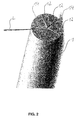
Fig. 1 zeigt einen kreisrunden Draht, der durch einen Laserstrahl in radialer Richtung in etwa bis zu dessen Mitte geschnitten wird. -
Fig. 2 zeigt das Erzeugen von insgesamt fünf Schnitten in einer radialen Richtung bis zur Mitte des Drahts. -
Fig. 3 zeigt ein Körbchen oder Filterdesign, das durch die Schnitte erzeugt wird, indem die abgeschnittenen Drahtsegmente anschließend aufgeweitet werden. -
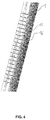
Fig. 4 zeigt einen Führungsdraht, der durch Erzeugen entsprechender Schnitte eine hohe Biegsamkeit bzw. Flexibilität aufweist. -
Fig. 5 zeigt einen Stent, der einstückig mit dem Führungsdraht hergestellt ist und eine Sollbruchstelle aufweist. -
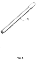
Fig. 6 zeigt einen steuerbaren Führungsdraht. -
Fig. 7 zeigt eine Detailansicht des Führungsdrahts vonFig. 6 mit einem entsprechenden Gelenk zum Abknicken des Führungsdrahts. -
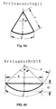
Fig. 8a zeigt ein Drahtsegment, das als Kreisausschnitt geformt ist, undFig. 8b zeigt ein Drahtsegment, das als Kreisabschnitt geformt ist. - Wie in
Fig. 1 gezeigt ist, wird ein kreisrunder Draht 1 durch einen Laserstrahl L mittels der Ultrakurzpuls-Lasertechnologie bis etwa zu dessen Mitte in radialer Richtung eingeschnitten, um einen Schnitt 12 zu erzeugen. Obwohl es vorteilhaft ist, kreisrunde Drähte für diese Technologie anzuwenden, ist die Erfindung nicht darauf beschränkt. Es können auch Drähte mit elliptischem Querschnitt, Dreikantdrähte, Vierkantdrähte, Fünfkantdrähte oder dergleichen verwendet werden. - Vorteilhafterweise wird dabei ein Ultrakurzpuls-Laser mit einer Wellenlänge von etwa 200 bis etwa 2000 nm eingesetzt. Die Impulsdauer sollte etwa 10 fs bis etwa 10 ps betragen.
- Der selektive Abtragungsprozess kann jedoch alternativ oder zusätzlich eines aus einem elektrochemischen Abtragen, einem Erodieren, einer Maskierung mit anschließendem Ätzen oder einer Ionenstrahlbearbeitung (Focused Ion Beam) aufweisen.
- Wie des weiteren in
Fig. 2 gezeigt ist, können beispielsweise fünf radiale Schnitte bis zur Mitte des Drahts 1 erzeugt werden, um Drahtsegmente oder geschnittene Abschnitte 14 zu erzeugen. Diese geschnittenen Abschnitte oder Drahtsegmente 14 können anschließend durch Verformen aufgeweitet werden, um beispielsweise ein Körbchen oder Filterdesign zu erzeugen, wie es beispielsweise inFig. 3 gezeigt ist. Dabei gehen die Schnitte nicht bis zu einem axialen Ende 1 a, 1 b des Drahts 1, so daß die einzelnen Drahtsegmente 14 an ihren Enden in Längsrichtung noch miteinander verbunden sind. - Auf diese Weise wird aus einem Draht 1 ein Körbchen bzw. Filter erzeugt, das Drahtsegmente 14 an den Enden 1a, 1 b einstückig oder integral verbunden aufweist.
- In anderen Worten wird der Draht 1 wie ein Kuchen in einzelne Segmente (Drahtsegmente 14) aufgetrennt, wobei axiale Enden 1 a, 1 b des Drahts nicht getrennt werden. Die aufgetrennten Drahtsegmente 14 werden aufgeweitet, so dass ein Körper mit beabstandeten Drahtsegmenten 14 in der axialen Mitte und einstückig mit den Drahtsegmenten 14 verbundenen axialen Enden 1 a, 1 b geformt wird.
- Um das Aufweiten zu erleichtern bzw. ein Verformungsverhalten des Körperimplantats zu beeinflussen, können Einschnitte 19 oder Einkerbungen zur gezielten Querschnittsschwächung an dem Draht 1 erzeugt werden, wie in
Fig. 3 gezeigt ist. Insbesondere sind die Einschnitte 19 bzw. Einkerbungen an ein oder mehreren Bereichen vorgesehen, an denen ein Steg bzw. Drahtsegment 14 in zwei oder mehrere Unterteilungen 14' unterteilt wird und/oder an denen zwei oder mehr Drahtsegmente 14 vereint werden (siehe oberen Bereich vonFig. 3 nahe dem axialen Ende 1 a). Ferner können ein oder mehrere Einschnitte 19 bzw. Einkerbungen in oder bei ein oder mehreren Bereichen des Stegs bzw. Drahtsegments 14 vorgesehen sein (siehe unteren Bereich vonFig. 3 nahe dem axialen Ende 1), in oder bei denen das jeweilige Drahtsegment bzw. Steg 14 durchgehend (d.h. nicht unterteilt) ausgebildet sind, wobei bevorzugt bei oder in Nähe der Einschnitt(e) 19 das jeweilige Drahtsegment bzw. Steg 14 gebogen oder nicht-linear ausgestaltet ist. - Durch die ein oder mehreren Schnitte, insbesondere durch die Querschnittsschwächung, können die elektrischen oder elektronischen Eigenschaften des entsprechenden Bereichs des Körperimplantats oder des medizinischen Instruments, insbesondere der elektrische Widerstand, so verändert bzw. eingestellt werden, dass beim Anlegen eines elektrischen Stroms lokal Wärme zum Abtöten von Körpergewebe erzeugt wird.
- Es versteht sich, dass die Erfindung auch mit drei, vier, sechs oder sieben Schnitten 12 etc. ausgeführt werden kann. Dabei müssen die Schnitte 12 nicht in gleichmässigen Winkelabständen durchgeführt werden, sondern es können unterschiedlich große "Kuchenstücke" bzw. Drahtsegmente 14 erzeugt werden.
- Darüber hinaus müssen die Drahtsegmente 14 nicht als Kreisausschnitte mit der Länge des Radius r des Drahts 1 als Seiten des Kreisausschnitts erzeugt werden, d.h. durch Schnitte 12, die im Mittelpunkt des Drahtquerschnitts enden, wie in
Fig. 8a gezeigt ist, sondern es können beliebige Formen, wie beispielsweise ein Kreisabschnitt von dem Drahtquerschnitt getrennt werden, wie beispielsweise inFig. 8b gezeigt ist. - Ein Kreisabschnitt, wie in
Fig. 8b gezeigt ist, wird dadurch von dem Drahtquerschnitt herausgetrennt, dass ein Schnitt 12 versetzt zu dem Mittelpunkt des Drahtquerschnitts entlang der Sehnenlänge s erzeugt wird. Dabei ist eine Höhe h des Schnitts 12 geringer als der Radius r des Drahts. - Indem auf diese Weise Drahtsegmente 14 mit unterschiedlichen Querschnitten von dem Drahtquerschnitt getrennt und anschließend aufgeweitet werden, kann beispielsweise ein Stent erzeugt werden, der unterschiedliche Stützkräfte entlang seines Umfangs aufweist.
- Diese Drahtsegmente 14 können einer weiteren Formgebung durch Umformen oder weitere Laserbearbeitung entsprechend den gewünschten mechanischen und/oder elektrischen Eigenschaften verformt oder bearbeitet werden. Darüber hinaus können die Drahtsegmente 14 verflochten werden, beispielsweise.durch Klöppeln der Drahtsegmente mit den Bindungsarten 1/2, 1/1 oder 2/2. Die Drahtsegmente 14 können daher entsprechende Stege 14 eines Stents 18 ausbilden.
- Das somit erzeugte Körbchen oder Filterdesign bzw. Stent 18 kann anschließend vom Draht 1 getrennt werden. Es kann jedoch auch an einem längeren Stück Draht 1 verbleiben, so daß das nicht geschnittene Ende des Drahts 1 als Führungsdraht 16 verwendet wird, wie beispielsweise in
Figs. 4 und5 gezeigt ist. - Zwischen dem Führungsdraht 16 und dem erzeugten Körperimplantat 18 kann sich dabei eine Sollbruchstelle 20 befinden, so daß die Baugruppe aus dem Führungsdraht 16 und dem Körperimplantat 18, die auf diese Weise einstückig erzeugt wird, nach dem Einführen und Plazieren des Körperimplantats 18 an der Sollbruchstelle 20 getrennt werden kann, um den Führungsdraht 16 nach dem Plazieren des Körperimplantats 18 zu entfernen. Der Führungsdraht 16 kann dabei wie in
Fig. 4 gezeigt ist, entsprechende Schnitte 12 bzw. Querschnittsschwächungen bzw. Strukturen aufweisen, um eine hohe Biegsamkeit bzw. Flexibilität zu erzeugen. Die Sollbruchstelle 20 hat eine entsprechende Querschnittsschwächung 20a, um ein Abbrechen oder Ablösen an der Sollbruchstelle 20 zu erleichtern. - Wie des weiteren in den
Figuren 6 und7 gezeigt ist, kann durch einen Schnitt, bei dem fast der gesamte Querschnitt des Drahts bzw. Führungsdrahts 16 entfernt wird, ein entsprechendes Gelenk 17 erzeugt werden, um das ein Ende des Führungsdrahts 16 gegenüber einem anderen Abschnitt gebogen werden kann. - Es ergeben sich somit vielfältige Designmöglichkeiten, indem ein Draht 1 durch den selektiven Abtragungsprozess, wie beispielsweise die UKP-Lasertechnologie, entsprechend geschnitten wird und die geschnittenen Drahtsegmente 14 eventuell aufgeweitet und/oder weiter bearbeitet werden. Auf diese Weise kann ein Körperimplantat 18, wie beispielsweise ein Stent, ein Körbchen oder ein Filter, einstückig auf einfache Weise hergestellt werden. Darüber hinaus kann dieses Körperimplantat 18 bis zum ursprünglichen Drahtdurchmesser gecrimpt werden, um eine maximale Durchmesserverringerung zu erzielen.
- Vorzugsweise wird ein Draht 1 aus einem Material mit Formgedächtniseigenschaften wie beispielsweise Nitinol verwendet. Es können jedoch auch andere Metalle oder auch Nichtmetalle, wie beispielsweise Polymere verwendet werden. Beispiele hierfür sind ein Polymer ohne Formgedächtnis, ein Formgedächtnispolymer, ein bioresorbierbares Polymer und/oder ein nicht bioresorbierbares Polymer, und/oder ein Metall, wie beispielsweise ein reines Metall, eine Legierung und/oder eine Formgedächtnislegierung, und/oder eine Keramik.
- Die Erfindung ist nicht auf das Erzeugen von radialen Schnitten 12 beschränkt, die Schnitte können auch in anderen Richtungen erzeugt werden. Darüber hinaus müssen die Schnitte 12 nicht bis zur Mitte des Drahts 1 gehen, sondern können, je nach Anwendungsfall, weniger tief oder tiefer erzeugt werden. Hierdurch können Strukturen oder Einkerbungen an dem Querschnitt des Drahts 1 erzeugt werden.
-
- 1
- Draht
- 12
- Schnitt
- 14
- Drahtsegment (Steg)
- 14'
- Unterteilung
- 16
- Führungsdraht
- 17
- Gelenk (Struktur)
- 18
- Körperimplantat (Stent)
- 19
- Einkerbung bzw. Einschnitt (Struktur)
- 20
- Sollbruchstelle (Struktur)
- 20a
- Querschnitttsschwächung (Struktur)
- L
- Laser
Claims (14)
- Verfahren zum Herstellen eines Körperimplantats (18) oder medizinischen Instruments mit den Schritten:Bereitstellen eines Drahts (1);Erzeugen von vorgegebenen Schnitten (12) an dem Draht (1) mittels eines selektiven Abtragungsprozesses, um eine vorgegebene Gestalt des Körperimplantats (18) zu erzeugen,dadurch gekennzeichnet, dassdie Schnitte (12) in radialer Richtung bis etwa die Mitte des Drahts (1) erzeugt werden.
- Verfahren nach Anspruch 1, wobei der selektive Abtragungsprozeß zumindest teilweise mittels eines Ultrakurzpulslasers (L) durchgeführt wird.
- Verfahren nach einem der vorangehenden Ansprüche, wobei ein geschnittener Abschnitt (14) des Drahts (1) oder ein Drahtsegment aufgeweitet wird, um ein geschlossenes Körbchen oder ein Filter zu erzeugen.
- Verfahren nach einem der vorherigen Ansprüche, wobei durch die Schnitte (12) ein Teil des Querschnitts des Drahts (1) entfernt wird, um ein Gelenk (17) zu erzeugen.
- Verfahren nach einem der vorherigen Ansprüche, des weiteren mit dem Schritt des Verflechtens bzw. des Klöppelns von Drahtsegmenten und/oder eines Schritts einer Formgebung von Drahtsegmenten.
- Verfahren nach einem der vorherigen Ansprüche, wobei ein Draht (1) aus einem Polymer, wie bespielsweise einem Polymer ohne Formgedächtnis, einem Formgedächtnispolymer, einem bioresorbierbaren Polymer oder einem nicht bioresorbierbaren Polymer, und/oder einem Metall, wie beispielsweise einem reinen Metall, einer Legierung und/oder einer Formgedächtnislegierung, und/oder einer Keramik verwendet wird.
- Verfahren nach einem der vorherigen Ansprüche, wobei bei dem selektiven Abtragungsprozeß zumindest teilweise ein oder mehrere von folgenden Verfahren zum Einsatz kommen: ein elektrochemischer Abtragungsprozess, ein Erodieren, ein elektrochemisches Polieren, ein nasschemisches Ätzen, ein trocken-chemisches Ätzen, ein reaktives Ionenätzen, ein physikalisches Ionenätzen und/oder eine fokussierte Ionenstrahlbearbeitung.
- Verfahren nach einem der vorherigen Ansprüche, wobei durch Ausbildung von Schnitten mittels des selektiven Abtragungsprozesses ein oder mehrere Strukturen (17; 19; 20; 20a) auf bzw. in dem Draht (1) ausgebildet werden.
- Verfahren nach Anspruch 8, wobei die ausgebildete Struktur zumindest eine der folgenden Ausbildungen umfasst: ein Gelenk (17), eine Einkerbung (19), einen Einschnitt, eine Sollbruchstelle (20) und/oder eine Querschnittsschwächung (20a).
- Baugruppe aus einem Führungsdraht (16) und einem Körperimplantat (18) oder medizinischen Instrument, die mit einem Verfahren nach einem der vorherigen Ansprüche hergestellt ist, wobei Führungsdraht (16) und Körperimplantat (18) einstückig ausgebildet sind und eine Sollbruchstelle (20) aufweisen.
- Baugruppe nach Anspruch 10, wobei der Führungsdraht (1) zumindest ein einstückig ausgebildetes Gelenk (17) aufweist.
- Baugruppe nach einem der Ansprüche 10 oder 11, wobei das Körperimplantat (18) oder das medizinische Instrument zumindest eines aus einem Stent, einem Körbchen, oder einem Filter aufweist.
- Medizinisches Instrument mit einem Führungsdraht (16), das mit einem Verfahren nach einem der Ansprüche 1 bis 9 hergestellt ist.
- Medizinisches Instrument nach Anspruch 13, wobei der Führungsdraht (16) zumindest ein einstückig ausgebildetes Gelenk (17) aufweist.
Applications Claiming Priority (2)
| Application Number | Priority Date | Filing Date | Title |
|---|---|---|---|
| DE102012010687.4A DE102012010687B4 (de) | 2012-05-30 | 2012-05-30 | Verfahren zum Herstellen eines Körperimplantats, Baugruppe aus einem Führungsdraht und einem Körperimplantat sowie medizinisches Instrument |
| PCT/EP2013/001592 WO2013178361A1 (de) | 2012-05-30 | 2013-05-29 | Verfahren zum herstellen eines körperimplantats, baugruppe aus einem führungsdraht und einem körperimplantat sowie medizinisches instrument |
Publications (2)
| Publication Number | Publication Date |
|---|---|
| EP2855075A1 EP2855075A1 (de) | 2015-04-08 |
| EP2855075B1 true EP2855075B1 (de) | 2016-11-23 |
Family
ID=47683682
Family Applications (2)
| Application Number | Title | Priority Date | Filing Date |
|---|---|---|---|
| EP13703522.6A Active EP2683517B1 (de) | 2012-05-30 | 2013-01-22 | Verfahren zum herstellen eines körperimplantats, baugruppe aus einem führungsdraht und einem körperimplantat sowie medizinisches instrument |
| EP13729252.0A Active EP2855075B1 (de) | 2012-05-30 | 2013-05-29 | Verfahren zum herstellen eines körperimplantats |
Family Applications Before (1)
| Application Number | Title | Priority Date | Filing Date |
|---|---|---|---|
| EP13703522.6A Active EP2683517B1 (de) | 2012-05-30 | 2013-01-22 | Verfahren zum herstellen eines körperimplantats, baugruppe aus einem führungsdraht und einem körperimplantat sowie medizinisches instrument |
Country Status (4)
| Country | Link |
|---|---|
| US (2) | US10434605B2 (de) |
| EP (2) | EP2683517B1 (de) |
| DE (1) | DE102012010687B4 (de) |
| WO (2) | WO2013178297A1 (de) |
Families Citing this family (12)
| Publication number | Priority date | Publication date | Assignee | Title |
|---|---|---|---|---|
| DE102012010687B4 (de) | 2012-05-30 | 2021-08-19 | ADMEDES GmbH | Verfahren zum Herstellen eines Körperimplantats, Baugruppe aus einem Führungsdraht und einem Körperimplantat sowie medizinisches Instrument |
| DE102013113271B4 (de) * | 2012-12-17 | 2023-03-02 | Acandis Gmbh | Medizinisches Implantat, Behandlungssystem mit einem derartigen Implantat und Verfahren zum Herstellen eines Implantats |
| ES2577288B8 (es) | 2015-01-13 | 2019-01-10 | Anaconda Biomed S L | Dispositivo para trombectomía |
| US12575845B2 (en) | 2015-12-11 | 2026-03-17 | Anaconda Biomed, S.L. | Thrombectomy device, system and method for extraction of vascular thrombi from a blood vessel |
| US11771446B2 (en) | 2020-10-19 | 2023-10-03 | Anaconda Biomed, S.L. | Thrombectomy system and method of use |
| EP3639768A1 (de) | 2018-10-16 | 2020-04-22 | Anaconda Biomed, S.L. | Vorrichtung zur extraktion von thromben aus einem blutgefäss und einer thrombectomievorrichtung |
| US12569264B2 (en) | 2018-10-16 | 2026-03-10 | Anaconda Biomed, S.L. | Device and a thrombectomy apparatus for extraction of thrombus from a blood vessel |
| WO2022028833A1 (en) | 2020-08-03 | 2022-02-10 | Anaconda Biomed, Sl | An elongated device with an improved attachment of its elements |
| US20230301807A1 (en) | 2020-08-03 | 2023-09-28 | Anaconda Biomed, Sl | A clot mobilizer device for extraction of an occlusion from a blood vessel |
| ES3053657T3 (en) | 2021-02-26 | 2026-01-23 | Anaconda Biomed Sl | A self-expandable medical device for advancement through vasculature to an expansion site in a blood vessel |
| JP2025501729A (ja) | 2021-12-21 | 2025-01-23 | アナコンダ ビオメッド, エス.エル. | その要素のアタッチメントを改善した血管内デバイス及びその製造方法 |
| DE102022114379A1 (de) * | 2022-06-08 | 2023-12-14 | Acandis Gmbh | Medizinische Vorrichtung und Herstellungsverfahren |
Family Cites Families (82)
| Publication number | Priority date | Publication date | Assignee | Title |
|---|---|---|---|---|
| CA2117088A1 (en) * | 1991-09-05 | 1993-03-18 | David R. Holmes | Flexible tubular device for use in medical applications |
| FR2685190B1 (fr) * | 1991-12-23 | 1998-08-07 | Jean Marie Lefebvre | Dispositif rotatif d'atherectomie ou de thrombectomie a developpement transversal centrifuge. |
| US5495668A (en) * | 1994-01-13 | 1996-03-05 | The Furukawa Electric Co., Ltd. | Manufacturing method for a supermicro-connector |
| US20030069522A1 (en) * | 1995-12-07 | 2003-04-10 | Jacobsen Stephen J. | Slotted medical device |
| US5707387A (en) * | 1996-03-25 | 1998-01-13 | Wijay; Bandula | Flexible stent |
| US6190402B1 (en) * | 1996-06-21 | 2001-02-20 | Musc Foundation For Research Development | Insitu formable and self-forming intravascular flow modifier (IFM) and IFM assembly for deployment of same |
| US5980514A (en) * | 1996-07-26 | 1999-11-09 | Target Therapeutics, Inc. | Aneurysm closure device assembly |
| DE19722429A1 (de) * | 1997-05-28 | 1998-12-03 | Optimed Medizinische Instr Gmb | Vorrichtung zum Einfangen und/oder Zerkleinern von Gegenständen in Hohlorganen |
| US5916235A (en) * | 1997-08-13 | 1999-06-29 | The Regents Of The University Of California | Apparatus and method for the use of detachable coils in vascular aneurysms and body cavities |
| DE19745294A1 (de) | 1997-10-14 | 1999-04-15 | Biotronik Mess & Therapieg | Verfahren zur Herstellung feinstrukturierter medizintechnischer Implantate |
| US6022369A (en) * | 1998-02-13 | 2000-02-08 | Precision Vascular Systems, Inc. | Wire device with detachable end |
| US20070142901A1 (en) * | 1998-02-17 | 2007-06-21 | Steinke Thomas A | Expandable stent with sliding and locking radial elements |
| US6500182B2 (en) * | 1998-03-27 | 2002-12-31 | Cook Urological, Incorporated | Minimally-invasive medical retrieval device |
| JP3684085B2 (ja) * | 1998-09-02 | 2005-08-17 | ペンタックス株式会社 | 内視鏡用ワイヤループ型処置具 |
| US6893450B2 (en) * | 1999-03-26 | 2005-05-17 | Cook Urological Incorporated | Minimally-invasive medical retrieval device |
| US6258117B1 (en) * | 1999-04-15 | 2001-07-10 | Mayo Foundation For Medical Education And Research | Multi-section stent |
| US6398791B1 (en) * | 1999-06-11 | 2002-06-04 | Scimed Life Systems Inc | Variable composite sheath with interrupted sections |
| US6579246B2 (en) * | 1999-12-22 | 2003-06-17 | Sarcos, Lc | Coronary guidewire system |
| US6790218B2 (en) * | 1999-12-23 | 2004-09-14 | Swaminathan Jayaraman | Occlusive coil manufacture and delivery |
| US6402771B1 (en) * | 1999-12-23 | 2002-06-11 | Guidant Endovascular Solutions | Snare |
| US6517888B1 (en) | 2000-11-28 | 2003-02-11 | Scimed Life Systems, Inc. | Method for manufacturing a medical device having a coated portion by laser ablation |
| US6551342B1 (en) * | 2001-08-24 | 2003-04-22 | Endovascular Technologies, Inc. | Embolic filter |
| ES2534590T3 (es) * | 2001-08-27 | 2015-04-24 | Dendron Gmbh | Dispositivo para la implantación de medios de oclusión |
| US7294146B2 (en) * | 2001-12-03 | 2007-11-13 | Xtent, Inc. | Apparatus and methods for delivery of variable length stents |
| US20040068314A1 (en) * | 2002-01-16 | 2004-04-08 | Jones Donald K. | Detachable self -expanding aneurysm cover device |
| US7060083B2 (en) * | 2002-05-20 | 2006-06-13 | Boston Scientific Scimed, Inc. | Foldable vaso-occlusive member |
| US7914467B2 (en) * | 2002-07-25 | 2011-03-29 | Boston Scientific Scimed, Inc. | Tubular member having tapered transition for use in a medical device |
| ITBS20020107A1 (it) * | 2002-11-25 | 2004-05-26 | Invatec Srl | Tubo metallico con almeno una parte di lunghezza a flessibilita' variabile. |
| US7678119B2 (en) * | 2003-01-15 | 2010-03-16 | Scimed Life Systems, Inc. | Medical retrieval device with frangible basket |
| JP2005095610A (ja) | 2003-08-29 | 2005-04-14 | Toshiba Corp | ステントの製造方法およびその製造装置ならびにステント |
| US7377925B2 (en) * | 2003-09-16 | 2008-05-27 | Minimally Invasive Devices, Llc | Fragmentation and extraction basket |
| EP1997456B1 (de) | 2004-02-13 | 2011-12-07 | Innovational Holdings, LLC | Medizinisches Beschichtungssystem sowie Beschichtungsverfahren für Drähte |
| US7632242B2 (en) * | 2004-12-09 | 2009-12-15 | Boston Scientific Scimed, Inc. | Catheter including a compliant balloon |
| US8523879B1 (en) * | 2005-03-31 | 2013-09-03 | Stuart J. Lind | Stone retriever for flexible endoscopes having small diameter working channels |
| US7828832B2 (en) * | 2005-04-18 | 2010-11-09 | Medtronic Vascular, Inc. | Intravascular deployment device with improved deployment capability |
| DE102005022688B4 (de) * | 2005-05-12 | 2011-06-30 | EPflex Feinwerktechnik GmbH, 72581 | Führungsdraht für ein medizinisches Instrument |
| WO2006124405A2 (en) * | 2005-05-12 | 2006-11-23 | C.R. Bard Inc. | Removable embolus blood clot filter |
| US7850708B2 (en) * | 2005-06-20 | 2010-12-14 | Cook Incorporated | Embolic protection device having a reticulated body with staggered struts |
| US8267872B2 (en) * | 2005-07-07 | 2012-09-18 | St. Jude Medical, Cardiology Division, Inc. | Steerable guide wire with torsionally stable tip |
| DE102005040214A1 (de) * | 2005-08-15 | 2007-03-01 | Epflex Feinwerktechnik Gmbh | Mehrdrahteinheit und Herstellungsverfahren hierfür |
| US7765014B2 (en) * | 2005-08-16 | 2010-07-27 | Medtronic, Inc. | Apparatus and methods for delivering transvenous leads |
| US8231669B2 (en) * | 2005-09-22 | 2012-07-31 | Boston Scientific Scimed, Inc. | Tether guided stent side branch |
| US8876772B2 (en) * | 2005-11-16 | 2014-11-04 | Boston Scientific Scimed, Inc. | Variable stiffness shaft |
| US7722636B2 (en) | 2005-11-30 | 2010-05-25 | Codman & Shurtleff, Inc. | Embolic device delivery system with torque fracture characteristic |
| US8251963B2 (en) * | 2005-12-08 | 2012-08-28 | Boston Scientific Scimed, Inc. | Flexible needle |
| US8292827B2 (en) * | 2005-12-12 | 2012-10-23 | Boston Scientific Scimed, Inc. | Micromachined medical devices |
| DE102006002531A1 (de) * | 2006-01-11 | 2007-07-12 | Epflex Feinwerktechnik Gmbh | Mehrdrahtinstrument, insbesondere für Endoskope |
| US20070225729A1 (en) * | 2006-03-21 | 2007-09-27 | Eric Cheng | Medical device basket legs of a plurality of materials |
| US7857008B2 (en) * | 2006-08-24 | 2010-12-28 | Boston Scientific Scimed, Inc. | Medical device coating configuration and method for improved lubricity and durability |
| JP2009297719A (ja) | 2006-10-02 | 2009-12-24 | Hikari Physics Kenkyusho:Kk | 細径管用のレーザー加工装置および加工方法 |
| US9149609B2 (en) * | 2006-10-16 | 2015-10-06 | Embolitech, Llc | Catheter for removal of an organized embolic thrombus |
| US8409114B2 (en) * | 2007-08-02 | 2013-04-02 | Boston Scientific Scimed, Inc. | Composite elongate medical device including distal tubular member |
| US8821477B2 (en) * | 2007-08-06 | 2014-09-02 | Boston Scientific Scimed, Inc. | Alternative micromachined structures |
| CA2852714C (en) * | 2007-08-13 | 2016-10-04 | Garth T. Webb | Inflatable intra ocular lens/lens retainer |
| US8974809B2 (en) | 2007-09-24 | 2015-03-10 | Boston Scientific Scimed, Inc. | Medical devices having a filter insert for controlled diffusion |
| US20090187211A1 (en) | 2007-12-21 | 2009-07-23 | Abbott Laboratories | Vena cava filter having hourglass shape |
| US7806919B2 (en) * | 2008-04-01 | 2010-10-05 | Medtronic Vascular, Inc. | Double-walled stent system |
| US20100102046A1 (en) | 2008-10-27 | 2010-04-29 | Bin Huang | Laser Machining Medical Devices With Localized Cooling |
| US8795254B2 (en) * | 2008-12-10 | 2014-08-05 | Boston Scientific Scimed, Inc. | Medical devices with a slotted tubular member having improved stress distribution |
| EP2413840B1 (de) * | 2009-04-02 | 2016-08-17 | Endoshape, Inc. | Gefässverschlussvorrichtungen |
| US9067332B2 (en) * | 2009-04-03 | 2015-06-30 | Scientia Vascular, Llc | Micro-fabricated catheter devices formed with hybrid materials |
| US9067333B2 (en) * | 2009-04-03 | 2015-06-30 | Scientia Vascular, Llc | Micro-fabricated guidewire devices having elastomeric fill compositions |
| AU2010266027B2 (en) * | 2009-06-24 | 2015-05-07 | Shifamed Holdings, Llc | Steerable medical delivery devices and methods of use |
| US8920369B2 (en) * | 2009-06-24 | 2014-12-30 | Shifamed Holdings, Llc | Steerable delivery sheaths |
| US8529596B2 (en) * | 2009-07-08 | 2013-09-10 | Concentric Medical, Inc. | Vascular and bodily duct treatment devices and methods |
| US8357178B2 (en) * | 2009-07-08 | 2013-01-22 | Concentric Medical, Inc. | Vascular and bodily duct treatment devices and methods |
| JP5685253B2 (ja) * | 2009-07-29 | 2015-03-18 | シー・アール・バード・インコーポレーテッドC R Bard Incorporated | 管状フィルター |
| US20110070358A1 (en) | 2009-09-20 | 2011-03-24 | Medtronic Vascular, Inc. | Method of forming hollow tubular drug eluting medical devices |
| GB0921240D0 (en) * | 2009-12-03 | 2010-01-20 | Angiomed Ag | Stent device delivery system and method of making such |
| EP4643824A3 (de) * | 2009-12-08 | 2026-01-07 | Avalon Medical Ltd. | Vorrichtung und system für den ersatz einer transkatheter-mitralklappe |
| US8888838B2 (en) * | 2009-12-31 | 2014-11-18 | W. L. Gore & Associates, Inc. | Endoprosthesis containing multi-phase ferrous steel |
| US20110160838A1 (en) * | 2009-12-31 | 2011-06-30 | Blanzy Jeffrey S | Endoprosthesis containing multi-phase ferrous steel |
| US8551159B2 (en) | 2010-04-01 | 2013-10-08 | Abbott Cardiovascular Systems Inc. | Implantable prosthesis having through-holes |
| US9795765B2 (en) * | 2010-04-09 | 2017-10-24 | St. Jude Medical International Holding S.À R.L. | Variable stiffness steering mechanism for catheters |
| US9144665B2 (en) * | 2010-08-09 | 2015-09-29 | Boston Scientific Limited | Flexible sheath assemblies and interventional catheter systems incorporating them |
| US9867725B2 (en) | 2010-12-13 | 2018-01-16 | Microvention, Inc. | Stent |
| US9072874B2 (en) * | 2011-05-13 | 2015-07-07 | Boston Scientific Scimed, Inc. | Medical devices with a heat transfer region and a heat sink region and methods for manufacturing medical devices |
| US9011480B2 (en) * | 2012-01-20 | 2015-04-21 | Covidien Lp | Aneurysm treatment coils |
| US8961550B2 (en) * | 2012-04-17 | 2015-02-24 | Indian Wells Medical, Inc. | Steerable endoluminal punch |
| US20130289701A1 (en) * | 2012-04-27 | 2013-10-31 | Medtronic Vascular, Inc. | Stent-graft prosthesis for placement in the abdominal aorta |
| DE102012010687B4 (de) | 2012-05-30 | 2021-08-19 | ADMEDES GmbH | Verfahren zum Herstellen eines Körperimplantats, Baugruppe aus einem Führungsdraht und einem Körperimplantat sowie medizinisches Instrument |
| EP3226748B1 (de) * | 2014-12-05 | 2020-11-04 | Boston Scientific Scimed, Inc. | Druckmessungsführungsdrähte |
-
2012
- 2012-05-30 DE DE102012010687.4A patent/DE102012010687B4/de active Active
-
2013
- 2013-01-22 WO PCT/EP2013/000185 patent/WO2013178297A1/de not_active Ceased
- 2013-01-22 US US14/404,336 patent/US10434605B2/en active Active
- 2013-01-22 EP EP13703522.6A patent/EP2683517B1/de active Active
- 2013-05-29 EP EP13729252.0A patent/EP2855075B1/de active Active
- 2013-05-29 WO PCT/EP2013/001592 patent/WO2013178361A1/de not_active Ceased
-
2017
- 2017-03-06 US US15/450,994 patent/US10583531B2/en active Active
Also Published As
| Publication number | Publication date |
|---|---|
| WO2013178361A1 (de) | 2013-12-05 |
| WO2013178297A1 (de) | 2013-12-05 |
| DE102012010687B4 (de) | 2021-08-19 |
| US20170173738A1 (en) | 2017-06-22 |
| EP2855075A1 (de) | 2015-04-08 |
| WO2013178297A8 (de) | 2014-04-24 |
| EP2683517A1 (de) | 2014-01-15 |
| US10434605B2 (en) | 2019-10-08 |
| DE102012010687A1 (de) | 2013-12-05 |
| EP2683517B1 (de) | 2015-09-16 |
| US10583531B2 (en) | 2020-03-10 |
| US20150165558A1 (en) | 2015-06-18 |
Similar Documents
| Publication | Publication Date | Title |
|---|---|---|
| WO2013178361A1 (de) | Verfahren zum herstellen eines körperimplantats, baugruppe aus einem führungsdraht und einem körperimplantat sowie medizinisches instrument | |
| EP1420701B1 (de) | Vorrichtung zur implantation von occlusionsmitteln | |
| EP3302372B1 (de) | Stent | |
| EP2995282B1 (de) | Vorgeformter stent | |
| DE212005000042U1 (de) | Medizinisches Implantat, beispielsweise Stent | |
| EP3025196B1 (de) | Verfahren zur herstellung einer medizinischen vorrichtung oder einer vorrichtung mit strukturelementen, verfahren zum modifizieren der oberfläche einer medizinischen vorrichtung oder einer vorrichtung mit strukturelementen, medizinische vorrichtung und schichtverbund mit einem substrat | |
| WO2008135002A1 (de) | Verfahren zur herstellung eines von aus einer vielzahl von parallel zu einander angeordneten drahtadern bestehenden drahtbandes sowie nach diesem verfahren hergestelltes drahtband | |
| EP3777739B1 (de) | Schneidelektrode, chirurgisches instrument und verfahren zur herstellung der schneidelektrode | |
| DE102013113271B4 (de) | Medizinisches Implantat, Behandlungssystem mit einem derartigen Implantat und Verfahren zum Herstellen eines Implantats | |
| EP3173044B1 (de) | Chirurgische vaporisationselektrode | |
| DE102013113263A1 (de) | Medizinisches Instrument für intravaskuläre Eingriffe und Herstellungsverfahren | |
| EP2385846A2 (de) | Medizinisches implantat und verfahren zur herstellung eines solchen implantats | |
| DE102021128698A1 (de) | Implantat, insbesondere Stent, und Herstellungsverfahren | |
| DE102020206670A1 (de) | Laserschneidverfahren und Laserschneidanlage | |
| DE102004026830B4 (de) | Verfahren zur Erzeugung von elektrolytisch korrodierbaren Ablösestellen in Okklusionsmitteln, Okklusionsmittel, Einführhilfe und Vorrichtung aus einer Einführhilfe und einem Okklusionsmittel | |
| DE102020201125A1 (de) | Verfahren zum elektrochemischen Abtragen | |
| DE102019208790A1 (de) | Verfahren und Vorrichtung zur generativen Herstellung eines Bauteils | |
| WO2010097235A1 (de) | Medizinisches implantat mit einer gitterstruktur, medizinische vorrichtung, verfahren zu dessen herstellung sowie verfahren zum einbringen des medizinischen implantats in ein zufuhrsystem | |
| DE102016118600A1 (de) | Medizinische Vorrichtung, bandförmige Gitterstruktur, Set und Verfahren zur Herstellung dergleichen | |
| DE102015010306A1 (de) | Chirurgische vaporisationselektrode | |
| WO2015140237A1 (de) | Verfahren zur herstellung eines schaltkontakts | |
| DE102013101980A1 (de) | Medizinische Vorrichtung, Behandlungssystem mit einer derartigen Vorrichtung und Verfahren zum Herstellen einer medizischen Vorrichtung |
Legal Events
| Date | Code | Title | Description |
|---|---|---|---|
| PUAI | Public reference made under article 153(3) epc to a published international application that has entered the european phase |
Free format text: ORIGINAL CODE: 0009012 |
|
| 17P | Request for examination filed |
Effective date: 20141113 |
|
| AK | Designated contracting states |
Kind code of ref document: A1 Designated state(s): AL AT BE BG CH CY CZ DE DK EE ES FI FR GB GR HR HU IE IS IT LI LT LU LV MC MK MT NL NO PL PT RO RS SE SI SK SM TR |
|
| AX | Request for extension of the european patent |
Extension state: BA ME |
|
| DAX | Request for extension of the european patent (deleted) | ||
| 17Q | First examination report despatched |
Effective date: 20151106 |
|
| REG | Reference to a national code |
Ref country code: DE Ref legal event code: R079 Ref document number: 502013005488 Country of ref document: DE Free format text: PREVIOUS MAIN CLASS: B23K0026060000 Ipc: A61F0002010000 |
|
| GRAP | Despatch of communication of intention to grant a patent |
Free format text: ORIGINAL CODE: EPIDOSNIGR1 |
|
| RIC1 | Information provided on ipc code assigned before grant |
Ipc: B23K 26/0622 20140101ALI20160330BHEP Ipc: A61F 2/91 20130101ALI20160330BHEP Ipc: B23K 26/364 20140101ALI20160330BHEP Ipc: A61F 2/01 20060101AFI20160330BHEP Ipc: A61B 17/221 20060101ALI20160330BHEP |
|
| INTG | Intention to grant announced |
Effective date: 20160428 |
|
| GRAP | Despatch of communication of intention to grant a patent |
Free format text: ORIGINAL CODE: EPIDOSNIGR1 |
|
| INTG | Intention to grant announced |
Effective date: 20160617 |
|
| GRAS | Grant fee paid |
Free format text: ORIGINAL CODE: EPIDOSNIGR3 |
|
| GRAA | (expected) grant |
Free format text: ORIGINAL CODE: 0009210 |
|
| AK | Designated contracting states |
Kind code of ref document: B1 Designated state(s): AL AT BE BG CH CY CZ DE DK EE ES FI FR GB GR HR HU IE IS IT LI LT LU LV MC MK MT NL NO PL PT RO RS SE SI SK SM TR |
|
| REG | Reference to a national code |
Ref country code: GB Ref legal event code: FG4D Free format text: NOT ENGLISH |
|
| REG | Reference to a national code |
Ref country code: CH Ref legal event code: EP |
|
| REG | Reference to a national code |
Ref country code: IE Ref legal event code: FG4D Free format text: LANGUAGE OF EP DOCUMENT: GERMAN |
|
| REG | Reference to a national code |
Ref country code: CH Ref legal event code: NV Representative=s name: PATENTANWAELTE SCHAAD, BALASS, MENZL AND PARTN, CH Ref country code: AT Ref legal event code: REF Ref document number: 847161 Country of ref document: AT Kind code of ref document: T Effective date: 20161215 |
|
| REG | Reference to a national code |
Ref country code: DE Ref legal event code: R096 Ref document number: 502013005488 Country of ref document: DE |
|
| PG25 | Lapsed in a contracting state [announced via postgrant information from national office to epo] |
Ref country code: LV Free format text: LAPSE BECAUSE OF FAILURE TO SUBMIT A TRANSLATION OF THE DESCRIPTION OR TO PAY THE FEE WITHIN THE PRESCRIBED TIME-LIMIT Effective date: 20161123 |
|
| REG | Reference to a national code |
Ref country code: LT Ref legal event code: MG4D |
|
| REG | Reference to a national code |
Ref country code: NL Ref legal event code: MP Effective date: 20161123 |
|
| REG | Reference to a national code |
Ref country code: FR Ref legal event code: PLFP Year of fee payment: 5 |
|
| PG25 | Lapsed in a contracting state [announced via postgrant information from national office to epo] |
Ref country code: SE Free format text: LAPSE BECAUSE OF FAILURE TO SUBMIT A TRANSLATION OF THE DESCRIPTION OR TO PAY THE FEE WITHIN THE PRESCRIBED TIME-LIMIT Effective date: 20161123 Ref country code: GR Free format text: LAPSE BECAUSE OF FAILURE TO SUBMIT A TRANSLATION OF THE DESCRIPTION OR TO PAY THE FEE WITHIN THE PRESCRIBED TIME-LIMIT Effective date: 20170224 Ref country code: NL Free format text: LAPSE BECAUSE OF FAILURE TO SUBMIT A TRANSLATION OF THE DESCRIPTION OR TO PAY THE FEE WITHIN THE PRESCRIBED TIME-LIMIT Effective date: 20161123 Ref country code: NO Free format text: LAPSE BECAUSE OF FAILURE TO SUBMIT A TRANSLATION OF THE DESCRIPTION OR TO PAY THE FEE WITHIN THE PRESCRIBED TIME-LIMIT Effective date: 20170223 Ref country code: LT Free format text: LAPSE BECAUSE OF FAILURE TO SUBMIT A TRANSLATION OF THE DESCRIPTION OR TO PAY THE FEE WITHIN THE PRESCRIBED TIME-LIMIT Effective date: 20161123 |
|
| PG25 | Lapsed in a contracting state [announced via postgrant information from national office to epo] |
Ref country code: RS Free format text: LAPSE BECAUSE OF FAILURE TO SUBMIT A TRANSLATION OF THE DESCRIPTION OR TO PAY THE FEE WITHIN THE PRESCRIBED TIME-LIMIT Effective date: 20161123 Ref country code: PT Free format text: LAPSE BECAUSE OF FAILURE TO SUBMIT A TRANSLATION OF THE DESCRIPTION OR TO PAY THE FEE WITHIN THE PRESCRIBED TIME-LIMIT Effective date: 20170323 Ref country code: FI Free format text: LAPSE BECAUSE OF FAILURE TO SUBMIT A TRANSLATION OF THE DESCRIPTION OR TO PAY THE FEE WITHIN THE PRESCRIBED TIME-LIMIT Effective date: 20161123 Ref country code: HR Free format text: LAPSE BECAUSE OF FAILURE TO SUBMIT A TRANSLATION OF THE DESCRIPTION OR TO PAY THE FEE WITHIN THE PRESCRIBED TIME-LIMIT Effective date: 20161123 Ref country code: ES Free format text: LAPSE BECAUSE OF FAILURE TO SUBMIT A TRANSLATION OF THE DESCRIPTION OR TO PAY THE FEE WITHIN THE PRESCRIBED TIME-LIMIT Effective date: 20161123 Ref country code: PL Free format text: LAPSE BECAUSE OF FAILURE TO SUBMIT A TRANSLATION OF THE DESCRIPTION OR TO PAY THE FEE WITHIN THE PRESCRIBED TIME-LIMIT Effective date: 20161123 |
|
| PG25 | Lapsed in a contracting state [announced via postgrant information from national office to epo] |
Ref country code: SK Free format text: LAPSE BECAUSE OF FAILURE TO SUBMIT A TRANSLATION OF THE DESCRIPTION OR TO PAY THE FEE WITHIN THE PRESCRIBED TIME-LIMIT Effective date: 20161123 Ref country code: EE Free format text: LAPSE BECAUSE OF FAILURE TO SUBMIT A TRANSLATION OF THE DESCRIPTION OR TO PAY THE FEE WITHIN THE PRESCRIBED TIME-LIMIT Effective date: 20161123 Ref country code: CZ Free format text: LAPSE BECAUSE OF FAILURE TO SUBMIT A TRANSLATION OF THE DESCRIPTION OR TO PAY THE FEE WITHIN THE PRESCRIBED TIME-LIMIT Effective date: 20161123 Ref country code: RO Free format text: LAPSE BECAUSE OF FAILURE TO SUBMIT A TRANSLATION OF THE DESCRIPTION OR TO PAY THE FEE WITHIN THE PRESCRIBED TIME-LIMIT Effective date: 20161123 Ref country code: DK Free format text: LAPSE BECAUSE OF FAILURE TO SUBMIT A TRANSLATION OF THE DESCRIPTION OR TO PAY THE FEE WITHIN THE PRESCRIBED TIME-LIMIT Effective date: 20161123 |
|
| REG | Reference to a national code |
Ref country code: DE Ref legal event code: R097 Ref document number: 502013005488 Country of ref document: DE |
|
| PG25 | Lapsed in a contracting state [announced via postgrant information from national office to epo] |
Ref country code: BG Free format text: LAPSE BECAUSE OF FAILURE TO SUBMIT A TRANSLATION OF THE DESCRIPTION OR TO PAY THE FEE WITHIN THE PRESCRIBED TIME-LIMIT Effective date: 20170223 Ref country code: LU Free format text: LAPSE BECAUSE OF NON-PAYMENT OF DUE FEES Effective date: 20170531 Ref country code: SM Free format text: LAPSE BECAUSE OF FAILURE TO SUBMIT A TRANSLATION OF THE DESCRIPTION OR TO PAY THE FEE WITHIN THE PRESCRIBED TIME-LIMIT Effective date: 20161123 |
|
| PLBE | No opposition filed within time limit |
Free format text: ORIGINAL CODE: 0009261 |
|
| STAA | Information on the status of an ep patent application or granted ep patent |
Free format text: STATUS: NO OPPOSITION FILED WITHIN TIME LIMIT |
|
| 26N | No opposition filed |
Effective date: 20170824 |
|
| PG25 | Lapsed in a contracting state [announced via postgrant information from national office to epo] |
Ref country code: SI Free format text: LAPSE BECAUSE OF FAILURE TO SUBMIT A TRANSLATION OF THE DESCRIPTION OR TO PAY THE FEE WITHIN THE PRESCRIBED TIME-LIMIT Effective date: 20161123 |
|
| PG25 | Lapsed in a contracting state [announced via postgrant information from national office to epo] |
Ref country code: MC Free format text: LAPSE BECAUSE OF FAILURE TO SUBMIT A TRANSLATION OF THE DESCRIPTION OR TO PAY THE FEE WITHIN THE PRESCRIBED TIME-LIMIT Effective date: 20161123 |
|
| PG25 | Lapsed in a contracting state [announced via postgrant information from national office to epo] |
Ref country code: LU Free format text: LAPSE BECAUSE OF NON-PAYMENT OF DUE FEES Effective date: 20170529 |
|
| REG | Reference to a national code |
Ref country code: FR Ref legal event code: PLFP Year of fee payment: 6 |
|
| REG | Reference to a national code |
Ref country code: BE Ref legal event code: MM Effective date: 20170531 |
|
| PG25 | Lapsed in a contracting state [announced via postgrant information from national office to epo] |
Ref country code: BE Free format text: LAPSE BECAUSE OF NON-PAYMENT OF DUE FEES Effective date: 20170531 |
|
| PG25 | Lapsed in a contracting state [announced via postgrant information from national office to epo] |
Ref country code: MT Free format text: LAPSE BECAUSE OF FAILURE TO SUBMIT A TRANSLATION OF THE DESCRIPTION OR TO PAY THE FEE WITHIN THE PRESCRIBED TIME-LIMIT Effective date: 20161123 |
|
| PG25 | Lapsed in a contracting state [announced via postgrant information from national office to epo] |
Ref country code: HU Free format text: LAPSE BECAUSE OF FAILURE TO SUBMIT A TRANSLATION OF THE DESCRIPTION OR TO PAY THE FEE WITHIN THE PRESCRIBED TIME-LIMIT; INVALID AB INITIO Effective date: 20130529 |
|
| REG | Reference to a national code |
Ref country code: AT Ref legal event code: MM01 Ref document number: 847161 Country of ref document: AT Kind code of ref document: T Effective date: 20180529 |
|
| PG25 | Lapsed in a contracting state [announced via postgrant information from national office to epo] |
Ref country code: AT Free format text: LAPSE BECAUSE OF NON-PAYMENT OF DUE FEES Effective date: 20180529 Ref country code: CY Free format text: LAPSE BECAUSE OF FAILURE TO SUBMIT A TRANSLATION OF THE DESCRIPTION OR TO PAY THE FEE WITHIN THE PRESCRIBED TIME-LIMIT Effective date: 20161123 |
|
| PG25 | Lapsed in a contracting state [announced via postgrant information from national office to epo] |
Ref country code: MK Free format text: LAPSE BECAUSE OF FAILURE TO SUBMIT A TRANSLATION OF THE DESCRIPTION OR TO PAY THE FEE WITHIN THE PRESCRIBED TIME-LIMIT Effective date: 20161123 |
|
| PG25 | Lapsed in a contracting state [announced via postgrant information from national office to epo] |
Ref country code: TR Free format text: LAPSE BECAUSE OF FAILURE TO SUBMIT A TRANSLATION OF THE DESCRIPTION OR TO PAY THE FEE WITHIN THE PRESCRIBED TIME-LIMIT Effective date: 20161123 |
|
| PG25 | Lapsed in a contracting state [announced via postgrant information from national office to epo] |
Ref country code: AL Free format text: LAPSE BECAUSE OF FAILURE TO SUBMIT A TRANSLATION OF THE DESCRIPTION OR TO PAY THE FEE WITHIN THE PRESCRIBED TIME-LIMIT Effective date: 20161123 Ref country code: IS Free format text: LAPSE BECAUSE OF FAILURE TO SUBMIT A TRANSLATION OF THE DESCRIPTION OR TO PAY THE FEE WITHIN THE PRESCRIBED TIME-LIMIT Effective date: 20170323 |
|
| PGFP | Annual fee paid to national office [announced via postgrant information from national office to epo] |
Ref country code: DE Payment date: 20250521 Year of fee payment: 13 |
|
| PGFP | Annual fee paid to national office [announced via postgrant information from national office to epo] |
Ref country code: IT Payment date: 20250530 Year of fee payment: 13 |
|
| PGFP | Annual fee paid to national office [announced via postgrant information from national office to epo] |
Ref country code: FR Payment date: 20250527 Year of fee payment: 13 |
|
| PGFP | Annual fee paid to national office [announced via postgrant information from national office to epo] |
Ref country code: CH Payment date: 20250601 Year of fee payment: 13 |
|
| PGFP | Annual fee paid to national office [announced via postgrant information from national office to epo] |
Ref country code: IE Payment date: 20250521 Year of fee payment: 13 |
|
| PGFP | Annual fee paid to national office [announced via postgrant information from national office to epo] |
Ref country code: GB Payment date: 20260326 Year of fee payment: 14 |