EP2854925B1 - Subintimal re-entry device - Google Patents
Subintimal re-entry device Download PDFInfo
- Publication number
- EP2854925B1 EP2854925B1 EP13731535.4A EP13731535A EP2854925B1 EP 2854925 B1 EP2854925 B1 EP 2854925B1 EP 13731535 A EP13731535 A EP 13731535A EP 2854925 B1 EP2854925 B1 EP 2854925B1
- Authority
- EP
- European Patent Office
- Prior art keywords
- distal
- guide wire
- lumen
- penetration member
- catheter
- Prior art date
- Legal status (The legal status is an assumption and is not a legal conclusion. Google has not performed a legal analysis and makes no representation as to the accuracy of the status listed.)
- Active
Links
Images


Classifications
-
- A—HUMAN NECESSITIES
- A61—MEDICAL OR VETERINARY SCIENCE; HYGIENE
- A61B—DIAGNOSIS; SURGERY; IDENTIFICATION
- A61B17/00—Surgical instruments, devices or methods, e.g. tourniquets
- A61B17/34—Trocars; Puncturing needles
- A61B17/3417—Details of tips or shafts, e.g. grooves, expandable, bendable; Multiple coaxial sliding cannulas, e.g. for dilating
-
- A—HUMAN NECESSITIES
- A61—MEDICAL OR VETERINARY SCIENCE; HYGIENE
- A61B—DIAGNOSIS; SURGERY; IDENTIFICATION
- A61B17/00—Surgical instruments, devices or methods, e.g. tourniquets
- A61B17/32—Surgical cutting instruments
- A61B17/3205—Excision instruments
- A61B17/3207—Atherectomy devices working by cutting or abrading; Similar devices specially adapted for non-vascular obstructions
-
- A—HUMAN NECESSITIES
- A61—MEDICAL OR VETERINARY SCIENCE; HYGIENE
- A61M—DEVICES FOR INTRODUCING MEDIA INTO, OR ONTO, THE BODY; DEVICES FOR TRANSDUCING BODY MEDIA OR FOR TAKING MEDIA FROM THE BODY; DEVICES FOR PRODUCING OR ENDING SLEEP OR STUPOR
- A61M25/00—Catheters; Hollow probes
- A61M25/01—Introducing, guiding, advancing, emplacing or holding catheters
- A61M25/0105—Steering means as part of the catheter or advancing means; Markers for positioning
- A61M25/0133—Tip steering devices
- A61M25/0136—Handles therefor
-
- A—HUMAN NECESSITIES
- A61—MEDICAL OR VETERINARY SCIENCE; HYGIENE
- A61M—DEVICES FOR INTRODUCING MEDIA INTO, OR ONTO, THE BODY; DEVICES FOR TRANSDUCING BODY MEDIA OR FOR TAKING MEDIA FROM THE BODY; DEVICES FOR PRODUCING OR ENDING SLEEP OR STUPOR
- A61M25/00—Catheters; Hollow probes
- A61M25/01—Introducing, guiding, advancing, emplacing or holding catheters
- A61M25/0194—Tunnelling catheters
-
- A—HUMAN NECESSITIES
- A61—MEDICAL OR VETERINARY SCIENCE; HYGIENE
- A61B—DIAGNOSIS; SURGERY; IDENTIFICATION
- A61B17/00—Surgical instruments, devices or methods, e.g. tourniquets
- A61B17/22—Implements for squeezing-off ulcers or the like on the inside of inner organs of the body; Implements for scraping-out cavities of body organs, e.g. bones; Calculus removers; Calculus smashing apparatus; Apparatus for removing obstructions in blood vessels, not otherwise provided for
- A61B2017/22038—Implements for squeezing-off ulcers or the like on the inside of inner organs of the body; Implements for scraping-out cavities of body organs, e.g. bones; Calculus removers; Calculus smashing apparatus; Apparatus for removing obstructions in blood vessels, not otherwise provided for with a guide wire
- A61B2017/22042—Details of the tip of the guide wire
- A61B2017/22044—Details of the tip of the guide wire with a pointed tip
-
- A—HUMAN NECESSITIES
- A61—MEDICAL OR VETERINARY SCIENCE; HYGIENE
- A61B—DIAGNOSIS; SURGERY; IDENTIFICATION
- A61B17/00—Surgical instruments, devices or methods, e.g. tourniquets
- A61B17/22—Implements for squeezing-off ulcers or the like on the inside of inner organs of the body; Implements for scraping-out cavities of body organs, e.g. bones; Calculus removers; Calculus smashing apparatus; Apparatus for removing obstructions in blood vessels, not otherwise provided for
- A61B2017/22094—Implements for squeezing-off ulcers or the like on the inside of inner organs of the body; Implements for scraping-out cavities of body organs, e.g. bones; Calculus removers; Calculus smashing apparatus; Apparatus for removing obstructions in blood vessels, not otherwise provided for for crossing total occlusions, i.e. piercing
- A61B2017/22095—Implements for squeezing-off ulcers or the like on the inside of inner organs of the body; Implements for scraping-out cavities of body organs, e.g. bones; Calculus removers; Calculus smashing apparatus; Apparatus for removing obstructions in blood vessels, not otherwise provided for for crossing total occlusions, i.e. piercing accessing a blood vessel true lumen from the sub-intimal space
-
- A—HUMAN NECESSITIES
- A61—MEDICAL OR VETERINARY SCIENCE; HYGIENE
- A61M—DEVICES FOR INTRODUCING MEDIA INTO, OR ONTO, THE BODY; DEVICES FOR TRANSDUCING BODY MEDIA OR FOR TAKING MEDIA FROM THE BODY; DEVICES FOR PRODUCING OR ENDING SLEEP OR STUPOR
- A61M25/00—Catheters; Hollow probes
- A61M25/01—Introducing, guiding, advancing, emplacing or holding catheters
- A61M25/0194—Tunnelling catheters
- A61M2025/0197—Tunnelling catheters for creating an artificial passage within the body, e.g. in order to go around occlusions
Definitions
- This disclosure relates to devices and methods for recanalization of an occluded blood vessel. More particularly, the disclosure is directed to devices and methods for re-entry into the true lumen from the subintimal space of the blood vessel.
- Chronic Total Occlusion is an arterial vessel blockage that obstructs blood flow through a vessel, and it can occur in both coronary and peripheral arteries.
- CTO Chronic Total Occlusion
- techniques have been developed for creating a subintimal pathway (a path between the intimal and adventitial tissue layers of the vessel wall) around the occlusion and then re-entering the true lumen of the vessel distal of the occlusion.
- re-entering the true lumen from the subintimal space and/or recanalization pathway may be difficult. Accordingly, it is desirable to provide alternative recanalization devices and/or methods having improved re-entry mechanisms for recanalization of a blood vessel in which a CTO is present.
- US 2003/0109809 A1 discloses an apparatus for deploying a needle within a lumen of a blood vessel.
- the apparatus includes a housing having a threaded bushing radially disposed therein.
- the bushing rigidly couples with a nose cone having a guide tip disposed at an end opposite the bushing for penetrating an arterial wall of a lumen.
- a user incrementally advances the bushing within the housing, thereby incrementally advancing the guide tip into the lumen of the blood vessel.
- the nose cone also includes a flex guide having a slot configuration which couples with the guide tip which deploys into the lumen along with the guide tip.
- EP 1 598 015 A1 discloses an apparatus for use with an invasive medical procedure into human breast tissue.
- the apparatus includes a cannula formed of a magnetic resonance imaging (MRI) compatible material and including an open proximal end and a more distal opening, an obturator comprising a hollow shaft formed of MRI compatible material and sized for insertion into the cannula and including a structure proximate to the more distal opening of the cannula when thus inserted to control prolapsing of tissue therein, an MRI imagable portion of the obturator proximate to the more distal opening of the cannula accentuating identification thereof, and a lumen formed in the obturator communicating between a proximal portion external to the human breast tissue and the more distal opening of the cannula.
- MRI magnetic resonance imaging
- US 6,514,217 B1 discloses a deflecting catheter for crossing occluded blood vessel having a catheter body and a cannula.
- the cannula comprises a distal length and a tip.
- the catheter body includes a single lumen and a deflecting housing secured to the distal end thereof.
- the deflecting housing comprises a lateral opening and a distal port.
- the deflecting catheter provides lateral deflection to the distal tip of the cannula which extends beyond the catheter body through the lateral opening in the deflector housing.
- the distal port permits introduction of the deflecting catheter over the proximal end of a guide wire.
- the distal length of the cannula may be straightened and deflected by axially retracting and advancing the cannula.
- the subintimal recanalization catheter of the present invention is defined by the features of the claims.
- the disclosure is directed to several alternative designs and methods of using medical device structures and assemblies, and uses thereof.
- one illustrated embodiment not being part of the present invention is a catheter for recanalizing a blood vessel having an occlusion therein.
- the catheter includes an elongate shaft having a proximal end, a distal end, and a guide wire lumen extending therethrough to a distal guide wire port
- the elongate shaft includes a proximal portion having a tubular shape and a distal portion having a flattened shape, the flattened shape including first and second wings extending in opposite directions configured to facilitate orientation of the distal portion within a subintimal space of a vessel.
- a deflection wire extends from the proximal end to the distal end of the elongate shaft, wherein actuation of the deflection wire causes the distal portion of the elongate shaft to deflect into a curved configuration to orient the distal guide wire port toward a true lumen of the vessel.
- a catheter including an elongate shaft including a first tubular member and a penetration member slidably disposed in a lumen of the first tubular member.
- the penetration member includes a distal tip positioned proximal of a distal nose of the first tubular member.
- the distal nose of the first tubular member includes a ramp and a guide wire lumen extending through the distal nose of the first tubular member. The longitudinal movement of the penetration member relative to the first tubular member causes the penetration member to contact the ramp to direct the distal tip of the penetration member away from the first tubular member.
- Yet another illustrative embodiment not being part of the present invention is a method for recanalizing a blood vessel having an occlusion therein.
- the method includes advancing a guide wire through a lumen of a blood vessel to a location proximal of a proximal end of an occlusion.
- a distal end of the guide wire is directed out of the lumen of the blood vessel and between a first tissue layer and a second tissue layer of a wall of the vessel to a location distal of a distal end of the occlusion.
- a recanalization catheter is advanced along the guide wire with the guide wire passing through a guide wire lumen of the recanalization catheter.
- the recanalization catheter includes a first tubular member and a penetration member slidably disposed in a lumen of the first tubular member.
- the penetration member includes a distal tip positioned proximal of a distal nose of the first tubular member, and the distal nose of the first tubular member includes a ramp and the guide wire lumen extending through the distal nose of the first tubular member.
- the distal nose is positioned between the first tissue layer and the second tissue layer at a location distal of the distal end of the occlusion.
- the penetration member is actuated relative to the first tubular member to cause the penetration member to contact the ramp and direct the distal tip of the penetration member away from the first tubular member, and re-enter the lumen of the blood vessel distal of the distal end of the occlusion.
- the present disclosure provides methods and systems to re-enter the true lumen of a blood vessel during recanalization of the blood vessel.
- the methods and systems may employ a catheter having a catheter shaft, a distal nose, and a penetration member, including a guide wire, and a guide wire lumen disposed within the catheter.
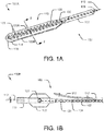
- FIGS. 1A-1C An exemplary subintimal recanalization catheter 100 is illustrated in FIGS. 1A-1C .
- the catheter 100 includes a distal portion 100A shown in FIG. 1A , and a proximal portion 100B shown in FIG. 1B . Further, an alternative embodiment of a proximal portion 100C is shown in FIG. 1C , respectively.
- the catheter 100 may include a first tubular member, an outer catheter shaft 102 extending between a proximal end 104 (shown in FIGS. 1B-C ) and a distal end 106.
- a second member, penetration member 108 may be slidably disposed within the catheter shaft 102 between the proximal end 104 and the distal end 106.
- a guide wire 112 may act as the penetration member 108.
- a separate penetration member 108 may be used.
- a hub assembly 109 having one or more ports may connect to the proximal end 104, and a distal nose 110 may engage with the catheter shaft 102 at the distal end 106.
- the guide wire 112 may be slidably disposed within the penetration member 108 and the distal nose 110. In some instances, the guide wire 112 may be the penetration member 108.
- a distal tip 114 is disposed at the distal end of the distal nose 110, and the distal tip 114 may include a guide wire port 116 to extend the guide wire 112 or the penetration member 108 distally beyond catheter 100.
- the catheter 100 may be configured to be advanced over the guide wire 112 for delivery to a remote location in the vasculature of a patient
- the catheter 100 may be configured as a Single Operator Exchange (SOE) (Monorail or Rapid-Exchange) catheter having a rapid exchange port 117 near the distal end 106 for inserting the guide wire 112 into a guide wire lumen 120.
- SOE Single Operator Exchange
- the catheter 100 may be configured as an Over The Wire (OTW) catheter having a port 118 configured at hub assembly 109 for inserting the guide wire 112 into the guide wire lumen 120.
- OGW Over The Wire
- the catheter shaft 102 may be an elongate sheath or a tubular member adapted to move forward into a blood vessel lumen.
- the catheter shaft 102 may be configured with a substantially circular cross section extending between the proximal and distal ends 104, 106.
- Other suitable cross-sectional shapes of the catheter shaft 102 may be elliptical, oval, polygonal, or irregular.
- the catheter shaft 102 may be flexible along its entire length or adapted for flexure along portions of its length. Flexibility may allow the catheter shaft 102 to navigate through turns in body lumens, while rigidity provides the necessary force to urge the catheter shaft 102 forward.
- the cross-sectional dimensions of the catheter shaft 102 may vary according to the desired application, but they are generally smaller than the typical thickness of the blood vessel wall in locations where the catheter 100 may be used, such as in a coronary artery.
- the length of the catheter shaft 102 may vary according to the location of the vessel lumen where subintimal recanalization is to be conducted.
- the distal end 106 of the catheter shaft 102 may have a tapering structure similar to a wedge or a cone. Alternatively, the distal end 106 may not have a tapering structure.
- the hub assembly 109 at the proximal end 104 may include components such as one or more ports to insert various medical devices into the lumen of the catheter shaft 102.
- the hub assembly 109 may include a handle (not shown) for the operator to hold the catheter 100, and one or more actuation means (not shown) to control the guide wire 112 and/or the distal nose 110.
- Catheter shaft 102 may be made of any suitable biocompatible material such as a polymeric or metallic material.
- the catheter shaft 102 may also be coated using a suitable low friction material, such as TEFLON®, polyetheretherketone (PEEK), polyimide, nylon, polyethylene, or other lubricious polymer coatings, to reduce surface friction with the surrounding tissues.
- a suitable low friction material such as TEFLON®, polyetheretherketone (PEEK), polyimide, nylon, polyethylene, or other lubricious polymer coatings, to reduce surface friction with the surrounding tissues.
- the penetration member 108 may be an elongate sheath slidably disposed within the guidewire lumen 120 of the catheter shaft 102, where the guide wire 112 may be also slidably disposed coaxially therewith.
- the guide wire 112 may be also slidably disposed coaxially therewith.
- only one of the penetration member 108 and the guide wire 112 may be present in the guidewire lumen 120 at the same time, thus requiring removal of one of the guide wire 112 or the penetration member 108 prior to advancing the other of the guide wire 112 or the penetration member 108 through the guidewire lumen 120.
- the penetration member 108 may extend from the rapid exchange port 117 to the distal end 106 in instances in which the catheter 100 is an SOE catheter, or the penetration member 108 may extend from port 118 to the distal end 106 in instances in which the catheter 100 is an OTW catheter.
- the penetration member 108 may have a substantially circular cross-section.
- the cross-sectional shape of the penetration member 108 may be any shape in which the guide wire 112 may easily maneuver, for instance, oval, polygonal, or tapering or any other shape capable of achieving the intended purpose in the intended environment.
- the penetration member 108 may be flexible or adapted for flexure along portions of its length. The flexibility of the penetration member 108 may or may not depend upon the flexibility of the catheter shaft 102.
- the cross-sectional dimensions of the penetration member 108 may be greater than the cross-sectional dimensions of the guide wire 112 and less than the cross-sectional dimensions of the catheter shaft 102.
- the distal end of the penetration member 108 may or may not engage with the distal nose 110 at the distal end 106.
- the distal end of the penetration member 108 may connect to the distal nose 110.
- the lumen of the penetration member 108 may be co-axial with the lumen of the distal nose 110 such that the guide wire 112 may pass from the penetration member 108 to the distal nose 110 without obstruction.
- the penetration member 108 may be formed of a metallic material, including a stainless steel or a nickel-titanium alloy such as nitinol.
- a polymeric material such as polyamide, polyether block amide, polyethylene, or polyethylene terepthalate or a combination of polymeric and metallic materials may be used to form the penetration member 108.
- a lubricious polymeric coating may be applied to the inner and/or the outer surface of the penetration member 108 to reduce friction between the penetration member 108 and the guide wire 112, and/or between the catheter shaft 102 and the penetration member 108.
- the lubricious polymeric coating may include suitable low friction materials such as TEFLON®, polyetheretherketone (PEEK), polyimide, nylon, polyethylene, or any other lubricious polymer coatings.
- the distal nose 110 may be a flattened structure engaged with and/or extending from the catheter shaft 102 at the distal end 106.
- the distal nose 110 may include the guide wire lumen 120 extending through a flattened portion 122 (shown as wings 122A-122B).
- the flattened portion 122 may extend the surface area of the distal nose 110 in a plane including the longitudinal axis of the distal nose 110, running along the length of the distal nose 110.
- the flattened portion 122 may facilitate in maintaining the orientation of the distal nose 110 parallel to the true lumen of a blood vessel during use as well as rotational orientation of the distal nose 110 such that the guide wire port 116 may be oriented toward the lumen of a blood vessel when deflected.
- the guide wire lumen 120 may be a hollow tubular structure that may allow passage of the guide wire 112 and/or the penetration member 108 therethrough and distally beyond the distal nose 110 into a blood vessel where the catheter 100 may be used.
- the guide wire lumen 120 may be configured with any suitable shape such as circular, oval, polygonal, or irregular.
- the guide wire lumen 120 may have cross-sectional dimensions greater than the cross-sectional dimensions of the guide wire 112 or the penetration member 108. Further, the cross-sectional dimensions of the guide wire lumen 120 may be less than the thickness of the blood vessel wall where the subintimal recanalization catheter 100 may be used.
- the flattened portion 122 includes two wings 122A-122B attached to the guide wire lumen 120.
- the wings 122A-122B may extend in opposite directions from the guide wire lumen 120.
- the wings 122A-122B may be rectangular, circular, oval, regular, or irregular-shaped members attached to the guide wire lumen 120 in a plane including the longitudinal axis of the guide wire lumen 120.
- the wings 122A-122B may be thicker near the guide wire lumen 120 and may taper regularly or irregularly towards the edges. Alternatively, the wings 122A-122B may be thicker at the edges and may taper towards the guide wire lumen 120.
- the wings 122A-122B may have a curvature extending outwardly from the plane including the longitudinal axis of the guide wire lumen 120 in either the same or opposing directions. Furthermore, the wings 122A-122B or portions thereof may be flexible or adapted for flexure. The wings 122A-122B may flex in a vessel wall to adapt to the shape of the vessel wall and follow the curvature of the vessel wall.
- FIG. 2 illustrates the cross section of the distal nose 110 taken across the plane 2-2.
- the wings 122A-122B may possess flexibility to adapt to the shape of a vessel wall.
- one or more reinforcing members may be included within the wings 122A-122B.
- the reinforcing members may facilitate the wings 122A-122B in adapting to the shape of the vessel wall, and they may further prevent the wings 122A-122B from flexing or bending into undesired shapes.
- Some exemplary reinforcing members may be metallic ribbons, braids, or wires.
- some embodiments may employ reinforcing strips 124 for shaping the distal nose 110.
- the strips 124 may run parallel to the elongate axis of the distal nose 110, and each wing 122A or 122B may include only one of the strips 124 or more than one of the strips 124.
- the strips 124 may be of any suitable dimensions that may fit into the wings 122A-122B.
- the strips 124 may allow the wings 122A-122B to flex into certain shapes, such as, the shape of the vessel wall.
- the strips 124 may prevent the wings 122A-122B from flexing into shapes that may hinder or obstruct the movement of the distal nose 110 within the vessel wall.
- the strips 124 may be made up of any polymeric or metallic materials such as stainless steel, nitinol, or polyamides to provide strength and stability to the wings 122A-122B. In some embodiments, as shown in FIG. 2 , the strips 124 may be metallic ribbons passing through a central portion of each wing 122A-122B.
- the wings 122A-122B may have dimensions suitable to separate and slide between the adventitia and intima layers of the desired blood vessel where the subintimal recanalization may be conducted.
- the span of the wings 122A-122B may be less than the circumference of the vessel wall.
- the thickness of the wings 122A-122B may be less than the thickness of the vessel wall, in some instances.
- FIGS. 3A-3B exhibit an alternative embodiment 300 of the distal nose (shown as distal nose 110 in FIG. 1A ), where FIG. 3A illustrates a cross sectional view of the distal nose 300, and FIG. 3B exhibits a perspective view of the distal nose 300.
- the flattened portion 122 is a paddle- or spatula-shaped member that includes the guide wire lumen 120. It may be noted that a person of ordinary skill in the art may envision many other embodiments for the flattened portion 122 capable of achieving the intended purpose in the intended environment.
- the flattened portion 122 may be any member attached to or formed with the catheter shaft 102 that may increase the surface area of the distal nose 300 (also show as distal nose 110 in FIG. 1A ) in a plane including the longitudinal axis of the distal nose 300.
- the distal tip 114 of the distal nose 110 may be a blunt or atraumatic tip shaped to prevent any inadvertent damage to a vessel walls upon contact with the distal tip 114.
- the distal tip 114 may assume any atraumatic shapes such as a blunt ball nose or a beveled or curved nose structure capable of achieving the intended purpose in the intended environment.
- the distal tip 114 may include the guide wire port 116 that may connect to the guide wire lumen 120 to extend the guide wire 112 distally beyond the distal tip 114.
- the distal nose 110 may be detachably connected, permanently coupled, or formed as an integral component of the catheter shaft 102.
- Distal nose 110 may be coupled to distal end 106 by any suitable coupling mechanism, such as assemblies joined by welding, molding, a snap fit, screw fit, luer-lock, or other known attachment mechanisms capable of achieving the intended purpose in the intended environment Suitable permanent coupling methods may include adhesive bonding, molding, or welding, depending on the distal nose 110 and/or catheter shaft 102 material.
- distal nose 110 may be formed integral with the distal end 106 of the catheter shaft 102.
- the distal nose 110 may be made up of any suitable biocompatible material.
- polymeric materials such as polyamide, polyetherblockamide, polyethylene, or polyethylene terepthalate may be used to make the distal nose 110.
- the distal nose 110, or portions thereof, may be made up of metallic materials such as stainless steel or nitinol, or a combination of polymeric and metallic materials.
- the guide wire lumen 120 and the wings 122A-122B may be made up of different material, attached during manufacture. In other embodiments, the wings 122A-122B may be detachable from the guide wire lumen 120.
- the guide wire lumen 120 and the wings 122A-122B may be formed as a single integral component.
- a lubricious polymeric coating may be used at the inner and/or the outer surface of the distal nose 110 to reduce friction between the guide wire lumen 120 and the guide wire 112, and between the vessel walls and the wings 122A-122B.
- the lubricious polymeric coating may include suitable low friction materials such as TEFLON®, polyetheretherketone (PEEK), polyimide, nylon, polyethylene, or any other lubricious polymer coatings.
- the guide wire 112 is a wire on which the catheter 100 may be configured to move forward for delivery to a remote distal location.
- the guide wire 112 may be a metallic or polymeric wire and/or a stylet.
- the guide wire 112 may be made up of biocompatible materials such as stainless steel or nitinol.
- the dimensions of guide wire 112 may depend on the application of the guide wire 112.
- the length of the guide wire 112 may depend on the length of the catheter 100, the target location within the vasculature, and the extent to which the guide wire 112 may need to extend beyond the distal tip 114.
- the diameter of the guide wire 112 may be less than the cross sectional dimensions of the penetration member 108 and/or the guide wire lumen 120 for insertion into the catheter 100.
- the embodiments of the present disclosure may include a deflection mechanism.
- the deflection mechanism may be any mechanism that may deflect the distal nose 110 and/or the penetration member 108 towards the true lumen of a blood vessel when the distal nose 110 is present in the subintimal space of the vessel wall.
- FIGS. 1B-C the present embodiment of the disclosure illustrates the use of a pull wire 126 as a deflection mechanism to deflect the distal nose 110 towards the true lumen of a blood vessel in a subintimal space.
- the pull wire 126 may be disposed within the catheter shaft 102 extending from the proximal end 104 to the distal end 106 (shown in FIG. 1A ) and through the distal nose 110 (shown in FIG.
- the pull wire 126 may be positioned ventrally, below the guide wire lumen 120.
- the wings 122A-122B of the flattened portion 122 may ensure proper rotational orientation such that the pull wire 126 is positioned between the guide wire lumen 120 and the lumen of a blood vessel.
- the pull wire 126 may be connected to any mechanism that may exert actuation and/or tension proximally on the pull wire 126 to deflect the distal nose 110.
- a rotatable knob 128 attached to the pull wire 126 as a pull mechanism may be used.
- the embodiment 100C shown in FIG. 1C may include a slidable button 130 connected to the proximal end of the pull wire 126.
- pull mechanisms 128, 130 illustrated in the disclosure are merely exemplary, and a person skilled in the art may utilize one of many suitable pull mechanisms known in the art to actuate (push or pull) the pull wire 126 capable of achieving the intended purpose in the intended environment.
- pull wire 126 may be tailored to specific environments.
- the pull wire 126 may have a length suitable to extend from the distal tip 114 to the proximal end 104.
- the diameter of the pull wire 126 may be large enough to provide the necessary strength to the pull wire 126 that may be required to deflect the distal nose 110.
- FIGS. 4A-4B Another embodiment of a re-entry catheter is illustrated in FIGS. 4A-4B , a catheter 400 including a distal portion 400A, shown in FIG. 4A , and a proximal portion 400B, shown in FIG. 4B .
- the distal portion 400A may include an opening 402 located proximally to the distal nose 110 near the distal end 106.
- the penetration member 108 may not extent into or through the guide wire lumen 120 of the distal nose 110, and the opening 402 may expose the distal end of the penetration member 108.
- the distal tip 403 of the penetration member 108 may be positioned proximal to the distal nose 110 co-axially aligned to the guide wire lumen 120.
- the guide wire 112 may extend through the penetration member 108 to the guide wire lumen 120 via a port 405 located at the distal tip 403.
- the penetration member 108 may be considered as a deflectable re-entry or redirection tube and may deflect away from the central axis of the catheter shaft 102 to extend out of the opening 402. In that instance, the deflected penetration member 108 may aid the guide wire 112 to puncture and penetrate the intima layer of a blood vessel.
- the penetration member 108 may include flexibility characteristics permitting the penetration member 108 to be deflectable away from the catheter shaft 102 into a curved or bent configuration.
- the penetration member 108 may include one or more cuts or slits 404 formed through the sidewalls of the penetration member 108, providing the penetration member 108 with a degree of lateral flexibility capable of achieving the intended purpose in the intended environment.
- the penetration member 108 may include a helical cut or slit 404 formed through the sidewalls of the penetration member 108.
- the helical cut or slit 404 may extend partially around the circumference of the penetration member 108 along a length of the penetration member 108, or another arrangement of cuts or slits 404 may be formed in another fashion to provide a desired degree of flexibility capable of achieving the intended purpose in the intended environment.
- the penetration member 108 may be formed from a hypo-tube using a laser, water jet, or any other cutting mechanisms used to form the cuts or slits 404 on the surface thereof.
- the penetration member 108 may be manufactured with cuts and slits 404 using 3D printing technologies.
- the proximal portion 400B shown in FIG. 4B may include an actuation device 406 that may facilitate an operator to actuate the penetration member 108 relative to the catheter shaft 102, to deflect the penetration member 108 towards the intima layer.
- the actuation device 406 may be an electronic or mechanical switch, a rotatable knob, push button, lever or other actuation mechanisms. Some exemplary deflection mechanisms are discussed in detail with FIGS. 9A-9B and 10A-10B below.
- FIGS. 5A-5D illustrate cross-sectional views of the distal portion 400A shown in FIG. 4A taken along the planes 5A-5A, 5B-5B, 5C-5C, and 5D-5D respectively.
- the catheter shaft 102 or a portion thereof may include an outer tubular member 502 representing a cross section of the catheter shaft 102 across plane 5A-5A.
- the penetration member 108 may extend through the lumen of the outer tubular member 502, and the guide wire 112 may extend through the lumen of the penetration member 108.
- FIG. 5B illustrates a cross section of the distal portion 400A shown in FIG. 4A taken along plane 5B-5B.
- the catheter shaft 102 shown in FIG. 4A
- the catheter shaft 102 or a portion thereof may include a crescent-shaped or "D" or "U”-shaped portion 508 including a lumen 510.
- the penetration member 108 may extend exterior to and below the crescent-shaped or "D"-shaped portion 508 running parallel to the crescent-shaped or D-shaped portion 508.
- the guide wire 112 may extend through the lumen of the penetration member 108. Referring to FIGS.
- the crescent-shaped or D-shaped portion 508 may define a cross section of the distal portion 400A across the plane 5B-5B passing through the opening 402.
- the lumen 510 may provide a path to extend the guide wire 112 to the guide wire lumen 120 in the distal nose 110.
- the crescent-shaped or D-shaped portion 508 may not restrict the penetration member 108 from moving towards the region opposite to the crescent-shaped or D-shaped portion 508.
- FIG. 5C illustrates a cross section of the distal portion 400A as shown in FIG. 4A taken along plane 5C-5C.
- the distal nose 110 shown in FIG. 4A
- the winged tubular portion 516 may include two wing-shaped structures 516A and 516B extending in opposite directions from a tubular portion 516C.
- the winged tubular portion 516 may define a cross section of the distal nose 110 across the plane 5C-5C shown in FIG. 4A .
- the tubular portion 516C may define a cross section of the guide wire lumen 120 and the two wing-shaped structures 516A-516B may describe wings 122A-122B of the distal nose 110.
- FIG. 5D illustrates a cross section of the embodiment of FIG. 4A taken along the plane 5D-5D.
- FIG. 5D illustrates two exemplary alternative embodiments 520A and 520B of a portion of the distal nose 110 near the distal tip 114.
- the embodiment 520A may include a tubular portion 522 and the guide wire 112 extending through the tubular portion 522.
- the tubular portion 522 may define a cross section of the guide wire lumen 120 across the plane 5D-5D shown in FIG. 4A .
- the embodiment 520B may include a crescent-shaped or D-shaped portion 526 defining cross sections of the guide wire lumen 120 along with the guide wire 112 extending through the crescent-shaped or D-shaped portion 526.
- the embodiment 520A exhibits that the guide wire lumen 120 may be a closed channel near the distal tip 114, while the embodiment 520B exhibits that the guide wire lumen 120 may be an open channel.
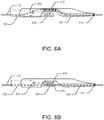
- FIGS. 6A-6B exhibit another alternative embodiment of the present disclosure.
- FIG. 6A exhibits a distal portion 600A
- FIG. 6B depicts a proximal portion 600B of a catheter 600.
- the penetration member 108 may include two or more ports 602 and 604 at a location proximate to the proximal end of the opening 402. The ports 602 and 604 are discussed further with FIG. 7 .
- a distal portion 606 of the penetration member 108 may extend from the port 604 towards the opening 402 such that the distal tip 403 of the distal portion 606 may lie proximal of the proximal end of the distal nose 110 within the opening 402.
- the distal portion 606 may engage with the guide wire lumen 120 by allowing the guide wire 112 to extend to the guide wire lumen 120 through port 405. In some other embodiments, the distal portion 606 may flex away from the longitudinal axis of the catheter shaft 102 through opening 402 directing the port 405 towards a vessel lumen (not shown). Further, the proximal portion 600B of catheter 600 shown in FIG. 6B may be similar to the proximal portion 400B of catheter 400 shown in FIG. 4B .
- FIG. 7 is a cross-sectional view of the distal portion 600A shown in FIG. 6A taken along plane 7-7.
- the catheter shaft 102 or a portion thereof may include an outer tubular member 702 defining the cross section of the catheter shaft 102 and the penetration member 108 extending through the outer tubular member 702.
- the ports 602 and 604 may connect to the lumen of the penetration member 108.
- the ports 602 and 604 may allow the operator to extend the guide wire 112 through alternative routes within the catheter 600.
- the alternative routes to extend the guide wire 112 are described below along with FIGS. 8A-8B .
- FIGS. 8A-8B illustrate alternative routes for the guide wire 112 within the distal portion 600A of catheter 600 shown in FIG. 6A .
- the operator may route the guide wire 112 from the penetration member 108 through port 602, lumen 510, and guide wire lumen 120 through the distal nose 110 to the guide wire port 116.
- the operator may route the guide wire 112 from within the penetration member 108 through port 604, distal portion 606, port 405 and guide wire lumen 120 through the distal nose 110 to the guide wire port 116.
- This feature of alternative routes may allow the operator to use the penetration member 108 to deflect towards the true lumen of a blood vessel within the vessel wall, which in turn may facilitate in subintimal re-entry through port 405.
- the distal portion 606 of the penetration member 108 may not deflect as the guide wire 112 may obstruct deflection.
- the distal portion 606 may be free to deflect away from the central axis of the catheter shaft 102 and may direct the port 405 towards the true lumen of a blood vessel within the vessel wall.
- the guide wire 112 may be re-routed through the distal portion 606 and port 405 towards the vessel lumen.
- Many mechanisms such as motors, hydraulics, strings, or shafts or other mechanisms capable of achieving the intended purpose in the intended environment may be used to deflect the distal portion 606.
- the penetration member 108 may not contain the ports 602 and 604. In such embodiments, the deflection mechanisms may deflect the entire penetration member 108. Furthermore, a person skilled in the art may appreciate that other embodiments may have a different deflection portion of the penetration member 108 and the deflection process may deviate from the exemplary process described in the following sections.
- FIGS. 9A-9B illustrate an exemplary deflection mechanism to deflect the penetration member 108 or its distal portion 606 towards the vessel lumen.
- FIG. 9A depicts a distal portion of a catheter 900 with the penetration member 108 in a non-deflected position.
- FIG. 9B depicts the distal portion of the catheter 900 with the penetration member 108 in a deflected position.
- the catheter 900 may be similar to the catheter 600 shown in FIGS. 6A-6B , and may include an additional component, a ramp 902 as a deflection mechanism.
- the ramp 902 may be a portion of or affixed on the distal nose 110 at the distal portion of the opening 402 having a slant running from its proximal end 904 near the central axis of the catheter shaft 102 to its distal end 906 at the edge of the catheter shaft 102.
- the ramp 902 may lie in a straight line with the central axis of the penetration member 108, in some instances.
- an actuation means such as the actuation device 406 shown in FIGS. 4B and 6B may actuate the penetration member 108 to move distally towards the ramp 902 to effectuate the deflection process. Due to this distal motion, the distal portion 606 of the penetration member 108 may hit the ramp 902 near the proximal end 904 and may deviate towards the distal end 906 along the slant of the ramp 902. This deviation may in turn deflect the distal portion 606 away from the central axis of the catheter shaft 102. Alternatively, in some embodiments, the actuation device 406 may actuate the distal nose 110 to move proximally along the central axis of the catheter shaft 102.
- FIGS. 10A-10B illustrate another exemplary deflection mechanism for deflecting the penetration member 108 or its distal portion 606 towards the vessel lumen.
- FIG. 10A depicts a distal portion of the catheter 1000 with the penetration member 108 in a non-deflected position.
- FIG. 10B exhibits the distal portion with the penetration member 108 in a deflected position.
- the catheter 1000 may be similar to the catheter 600 shown in FIGS. 6A-6B , and may include an actuable sleeve 1002 as a deflection mechanism.
- the penetration member 108 may be configured to be curved or deflected from a generally axially aligned configuration. In an equilibrium configuration, the penetration member 108 may extend from parallel to the catheter shaft 102 to a curved configuration in which the distal portion 606 of the penetration member 108 is curved away from the longitudinal axis of the catheter shaft 102.
- the distal portion 606 may be manufactured with a curvature or a bent structure such that the distal portion 606 when not constrained by the sleeve 1002 may automatically reconfigure to a curved position.
- a mechanism to selectively hold and release the pre-curved distal portion 606 within the catheter shaft 102 may be required.
- FIGS. 10A-10B illustrate one such mechanism using the sleeve 1002 to constrain the distal portion 606 in a straightened configuration.
- the actuable sleeve 1002 may be a sheath covering the catheter shaft 102 over the region of the opening 402.
- the sleeve 1002 may act as constraint to prevent the distal portion 606 from deflecting away from the central axis of the catheter shaft 102.
- the sleeve 1002 may be shaped such that it may extend over the catheter shaft 102.
- the sleeve 1002 may be made up of any metallic or polymeric material that may have enough strength to hold the curved distal portion 606 within the catheter shaft 102.
- an actuation means such as the actuation device 406 shown in FIGS. 4B and 6B may actuate the sleeve 1002.
- the actuation device 406 may be connected to the sleeve 1002 using any element such as a wire, a string, or a shaft.
- a wire 1004 may be connected to the sleeve 1002 to actuate it.
- the sleeve 1002 constraining the distal portion 606 of the penetration member 108 may move proximally along the central axis of the catheter shaft 102 allowing the distal portion 606 to automatically curve (deflect) away from the central axis of the catheter shaft 102 and out through the opening 402 when unconstrained by the sleeve 1002.
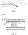
- FIG. 11 illustrates exemplary mechanisms for re-entry using the deflected distal portion 606.
- the deflected distal portion 606 may route the guide wire 112 towards the true lumen of the vessel through port 405. The guide wire 112 may then be advanced distally out of the distal port of the penetration member 108 and puncture the inner vessel wall to re-enter the true lumen of the vessel.
- the distal tip 403 of the penetration member 108 may be configured to facilitate piercing and/or dissection of the tissue layers of the blood vessel.
- the tip 403 may include a sharp, rigid, or piercing feature.
- the tip 403 may include an angled distal edge, providing the tip 403 with a sharpened cutting or piercing surface. The tip 403 may puncture the vessel wall and may route the guide wire 112 directly into the vessel lumen. It may be noted that the re-entry mechanisms discussed above are merely exemplary and a person of average skill in the art may contemplate other mechanisms for re-entry into the true lumen of a vessel using the deflected penetration member 108.
- FIGS. 12-16 illustrate aspects of an exemplary method for re-entering the true lumen of an occluded blood vessel using the catheter 100 of FIGS. 1A-1C .
- a blood vessel 1200 typically has three tissue layers, an innermost layer or intima layer 1202 (tunica intima), an intermediate layer or media layer 1204 (tunica media), and an outermost layer or adventitia layer 1206 (tunica adventitia), with the media layer 1204 positioned between the intima layer 1202 and the adventitia layer 1206.
- the intima layer 1202 is a layer of endothelial cells lining the lumen 1208 of the vessel 1200, as well as a sub-endothelial layer made up of mostly loose connective tissue.
- the media layer 1204 is a muscular layer formed primarily of circumferentially arranged smooth muscle cells.
- the adventitia layer 1206, which forms the exterior layer of the vessel 1200, is made up of loose connective tissue made up of fibroblasts and associated collagen fibers.
- a chronic total occlusion (CTO) 1210 may block the blood vessel 1200 and may stop the flow of fluids though the vessel lumen 1208.
- CTO chronic total occlusion
- the guide wire 112 may initially be moved forward through the lumen 1208 of the vessel 1200 to a location proximate a proximal end of the occlusion 1210, which is blocking the lumen 1208. The guide wire 112 may then be moved forward to penetrate outward through the intima layer 1202 at a location proximate a proximal end of the occlusion 1210 into the wall of the vessel 1200. With the tip of the guide wire 112 located between the intima layer 1202 and the adventitia layer 1206, the guide wire 112 may be further moved distally in a subintimal manner to create a subintimal space between the intima layer 1202 and the adventitia layer 1206.
- the guide wire 112 may be moved forward in a subintimal manner until the distal tip of the guide wire 112 is located distal of the distal end of the occlusion 1210 in the subintimal space created, such as by dissection of tissue layers of the wall of the vessel 1200.
- the recanalization catheter 100 may then be moved distally over the guide wire 112.
- the catheter 100 may be moved forward from the true lumen 1208, proximal of the occlusion 1210 into the subintimal space between the intima layer 1202 and the adventitia layer 1206, to a position in the subintimal space in which the distal nose 110 or a portion of it is located distal of the distal end of the occlusion 1210.
- the catheter 100 may then move forward into the subintimal space parallel to the intima layer 1202 until the catheter 100 or a portion of it approaches the desired position (distal of the distal end of the occlusion 1210).
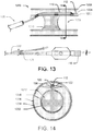
- FIG. 14 exhibits a cross section of the distal position of the catheter 100 positioned in the subintimal space created between the tissue layers of the vessel 1200 along the plane 14-14 distal of the occlusion 1210 in FIG. 13 .
- the vessel 1200 includes three tissue layers 1202, 1204, and 1206 along with the central lumen 1208 having the occlusion 1210.
- the cross section of the catheter 100 within the middle tissue layer 1204 includes a winged outer structure 122 representing a cross section of the distal nose 110, showing the guide wire lumen 120 with the guide wire 112 disposed within the guide wire lumen 120.
- the pull wire 126 is oriented such that the pull wire 126 is located ventrally, below the guide wire lumen 120 within the winged structure 122.
- the winged structure 122 may aid in providing stability to the catheter 100 (shown in FIG. 13 ) within the vessel 1200 by fixing the orientation of the catheter 100 parallel to the vessel lumen 1208 in the media layer 1204. Moreover, the parallel orientation of the catheter 100 within the wall of the vessel 1200 may keep the pull wire 126 below the guide wire lumen 120 (radially inward), which in turn may ensure deflecting the distal nose 110 towards the vessel lumen 1208 distal of the occlusion 1210.
- FIG. 15 illustrates the deflection of the distal tip 114 towards the vessel lumen 1208.
- the operator may actuate the pull mechanism using the knob 128 or slidable button 130 or other actuation member to deflect the distal tip 114.
- the pull wire 126 Once the pull wire 126 is pulled, it applies a deflecting force on the distal nose 110 forcing it to curve radially inwards.
- the pull wire 126 is disposed at a ventral location within the distal nose 110, the net force (acting on the distal nose 110) curves the distal nose 110 toward the vessel lumen 1208, thereby deflecting the distal tip 114 towards the intima layer 1202.
- FIG. 16 depicts the guide wire 112 advancing distally from the distal tip 114 and penetrating the intima layer 1202 and re-entering the true lumen 1208 of the vessel 1200.
- the pull wire 126 may deflect the distal tip 114 towards the intima layer 1202, which guides the guide wire port 116 toward the intima layer 1202.
- the operator may then extend the guide wire 112 distally through guide wire port 116 toward the intima layer 1202.
- the operator may force the guide wire 112 into the intima layer 1202 to puncture the intima layer 1202 and enter the true lumen 1208 of the vessel 1200. This process may rupture the intima layer 1202 and create a false lumen extending through the subintimal space from the proximal end to the distal end of the occlusion 1210.
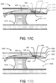
- FIGS. 17A-17D illustrate additional aspects of an exemplary method for re-entering the true lumen 1208 of an occluded blood vessel 1200 using the catheter 400 of FIGS. 4A and 4B or catheter 600 of FIGS. 6A and 6B .
- the guide wire 112 may initially move forward through the lumen 1208 and penetrate outward through the intima layer 1202 at a location proximate a proximal end of the occlusion 1210 into the vessel 1200.
- the guide wire 112 may then be advanced through the subintimal space to a location distal of the distal end of the occlusion 1210.
- the catheter 400 may then be advanced distally over the guide wire 112 from the true lumen 1208, proximal of the occlusion 1210 into the subintimal space, to a position where the distal nose 110 and the opening 402 is located distal of the distal end of the occlusion 1210.
- the operator may use any suitable deflection mechanism to deflect the penetration member 108 toward the lumen 1208.
- the deflection mechanisms described in FIGS. 9A-9B and 10A-10B may be used to deflect the penetration member 108 or its distal portion 606 to deflect and position the port 405 towards the intima layer 1202 through the opening 402.
- the operator may advance the penetration member 108 distally against the ramp 902 to deflect the penetration member 108.
- FIG. 17D illustrates the guide wire 112 penetrating the intima layer 1202.
- the penetration member 108 may route the guide wire 112 through port 405 towards the intima layer 1202, as illustrated in FIG. 11 .
- the operator may then extend the guide wire 112 from within the penetration member 108 towards the intima layer 1202 and may apply force to it to puncture the intima layer 1202.
- the guide wire 112 may puncture the intima layer 1202 and re-enter the true lumen 1208 of the vessel 1200.
- the deflection of the penetration member 108 with the sharp distal tip 403 may puncture the intima layer 1202 to create a re-entry path for the guide wire 112 by positioning the port 405 within the true lumen 1208 of the vessel 1200.
- one or more additional medical devices may be advanced through the blood vessel 1200 to enlarge the pathway and/or pass distally of the occlusion 1210 to perform a further medical procedure.
Description
- This disclosure relates to devices and methods for recanalization of an occluded blood vessel. More particularly, the disclosure is directed to devices and methods for re-entry into the true lumen from the subintimal space of the blood vessel.
- Chronic Total Occlusion (CTO) is an arterial vessel blockage that obstructs blood flow through a vessel, and it can occur in both coronary and peripheral arteries. In some instances, it may be difficult or impossible to penetrate the CTO with a medical device in an antegrade direction to recanalize the vessel. Accordingly, techniques have been developed for creating a subintimal pathway (a path between the intimal and adventitial tissue layers of the vessel wall) around the occlusion and then re-entering the true lumen of the vessel distal of the occlusion. In some instances, re-entering the true lumen from the subintimal space and/or recanalization pathway may be difficult. Accordingly, it is desirable to provide alternative recanalization devices and/or methods having improved re-entry mechanisms for recanalization of a blood vessel in which a CTO is present.
-
US 2003/0109809 A1 discloses an apparatus for deploying a needle within a lumen of a blood vessel. The apparatus includes a housing having a threaded bushing radially disposed therein. The bushing rigidly couples with a nose cone having a guide tip disposed at an end opposite the bushing for penetrating an arterial wall of a lumen. During operation, a user incrementally advances the bushing within the housing, thereby incrementally advancing the guide tip into the lumen of the blood vessel. The nose cone also includes a flex guide having a slot configuration which couples with the guide tip which deploys into the lumen along with the guide tip. -
EP 1 598 015 A1 -
US 6,514,217 B1 discloses a deflecting catheter for crossing occluded blood vessel having a catheter body and a cannula. The cannula comprises a distal length and a tip. The catheter body includes a single lumen and a deflecting housing secured to the distal end thereof. The deflecting housing comprises a lateral opening and a distal port. The deflecting catheter provides lateral deflection to the distal tip of the cannula which extends beyond the catheter body through the lateral opening in the deflector housing. The distal port permits introduction of the deflecting catheter over the proximal end of a guide wire. The distal length of the cannula may be straightened and deflected by axially retracting and advancing the cannula. - The subintimal recanalization catheter of the present invention is defined by the features of the claims.
- The disclosure is directed to several alternative designs and methods of using medical device structures and assemblies, and uses thereof.
- Accordingly, one illustrated embodiment not being part of the present invention is a catheter for recanalizing a blood vessel having an occlusion therein. The catheter includes an elongate shaft having a proximal end, a distal end, and a guide wire lumen extending therethrough to a distal guide wire port The elongate shaft includes a proximal portion having a tubular shape and a distal portion having a flattened shape, the flattened shape including first and second wings extending in opposite directions configured to facilitate orientation of the distal portion within a subintimal space of a vessel. A deflection wire extends from the proximal end to the distal end of the elongate shaft, wherein actuation of the deflection wire causes the distal portion of the elongate shaft to deflect into a curved configuration to orient the distal guide wire port toward a true lumen of the vessel.
- Another illustrative embodiment for re-entry into the true lumen from the subintimal space not being part of the present invention is a catheter including an elongate shaft including a first tubular member and a penetration member slidably disposed in a lumen of the first tubular member. The penetration member includes a distal tip positioned proximal of a distal nose of the first tubular member. The distal nose of the first tubular member includes a ramp and a guide wire lumen extending through the distal nose of the first tubular member. The longitudinal movement of the penetration member relative to the first tubular member causes the penetration member to contact the ramp to direct the distal tip of the penetration member away from the first tubular member.
- Yet another illustrative embodiment not being part of the present invention is a method for recanalizing a blood vessel having an occlusion therein. The method includes advancing a guide wire through a lumen of a blood vessel to a location proximal of a proximal end of an occlusion. A distal end of the guide wire is directed out of the lumen of the blood vessel and between a first tissue layer and a second tissue layer of a wall of the vessel to a location distal of a distal end of the occlusion. A recanalization catheter is advanced along the guide wire with the guide wire passing through a guide wire lumen of the recanalization catheter. The recanalization catheter includes a first tubular member and a penetration member slidably disposed in a lumen of the first tubular member. The penetration member includes a distal tip positioned proximal of a distal nose of the first tubular member, and the distal nose of the first tubular member includes a ramp and the guide wire lumen extending through the distal nose of the first tubular member. Furthermore, the distal nose is positioned between the first tissue layer and the second tissue layer at a location distal of the distal end of the occlusion. The penetration member is actuated relative to the first tubular member to cause the penetration member to contact the ramp and direct the distal tip of the penetration member away from the first tubular member, and re-enter the lumen of the blood vessel distal of the distal end of the occlusion.
- The above summary of some example embodiments is not intended to describe each disclosed embodiment or every implementation of the present disclosure.
- The invention may be more completely understood in consideration of the following detailed description of various embodiments in connection with the accompanying drawings, in which:
-
FIGS. 1A-1C illustrate an exemplary subintimal recanalization catheter, whereFIG. 1A depicts the distal portion, andFIGS. 1B and1C exhibit two alternative embodiments of the proximal portion of the catheter; -
FIG. 2 is an exemplary cross sectional view of the catheter apparatus taken across the plane 2-2; -
FIGS. 3A-3B illustrate an alternative embodiment of the distal nose of the catheter; -
FIGS. 4A-4B illustrate another embodiment of a subintimal recanalization catheter; -
FIGS. 5A-5D illustrate cross-sectional views of the exemplary catheter shown inFIG. 4 taken alongplanes 5A-5A, 5B-5B, 5C-5C, and 5D-5D respectively; -
FIGS. 6A-6B exhibit another alternative embodiment of a subintimal recanalization catheter; -
FIG. 7 is an exemplary cross-sectional view of the catheter ofFIG. 6A taken along plane 7-7; -
FIGS. 8A-8B illustrate two alternative routes for the guide wire within the embodiment of the catheter shown inFIG. 6A ; -
FIGS. 9A-9B illustrate an exemplary deflection mechanism to deflect the penetration member towards the vessel lumen; -
FIGS. 10A-10B depict another exemplary deflection mechanism to deflect the penetration member towards the vessel lumen; -
FIG. 11 is a side plan view of the embodiment of the catheter shown inFIGS. 6A-6B with the distal end of the penetration member projected away from the elongate axis of the catheter; -
FIGS. 12-16 illustrate aspects of an exemplary method for re-entering the true lumen of an occluded blood vessel using the catheter apparatus ofFIGS. 1A-1B ; -
FIGS.17A-17D illustrate aspects of another exemplary method for re-entering the true lumen of an occluded blood vessel using the catheter apparatus ofFIGS. 4A and 4B ; and -
FIG. 18 exhibits the penetration member of the catheter apparatus ofFIGS. 4A and 4B penetrating through the intima layer of the vessel wall. - While the invention of the present disclosure is amenable to various modifications and alternative forms, specifics thereof have been shown by way of example in the drawings and will be described in detail. It should be understood, however, that the intention is not to limit aspects of the invention to the particular embodiments described. On the contrary, the intention is to cover all modifications, equivalents, and alternatives falling within the scope of the invention as defined in the appended claims.
- For the following defined terms, these definitions shall be applied, unless a different definition is provided in the claims or elsewhere in this specification. All numeric values are herein assumed to be modified by the term "about," whether or not explicitly indicated. The term "about" generally refers to a range of numbers that one of skill in the art would consider equivalent to the recited value (i.e., having the same function or result). In many instances, the term "about" may be indicative as including numbers that are rounded to the nearest significant figure.
- The recitation of numerical ranges by endpoints includes all numbers within that range (e.g., 1 to 5 includes 1, 1.5, 2, 2.75, 3, 3.80, 4, and 5).
- Although some suitable dimensions ranges and/or values pertaining to various components, features, and/or specifications are disclosed, one of skill in the art, incited by the present disclosure, would understand desired dimensions, ranges and/or values may deviate from those expressly disclosed.
- As used in this specification and the appended claims, the singular forms "a," "an," and "the" include plural referents unless the content clearly dictates otherwise. As used in this specification and the appended claims, the term "or" is generally employed in its sense including "and/or" unless the content clearly dictates otherwise.
- The following detailed description should be read with reference to the drawings in which similar elements in different drawings are numbered the same. The detailed description and the drawings, which are not necessarily to scale, depict illustrative embodiments and are not intended to limit the scope of the invention. The illustrative embodiments depicted are intended only as exemplary. Selected features of any illustrative embodiment may be incorporated into an additional embodiment unless clearly stated to the contrary.
- While the devices and methods described herein are discussed relative to recanalization of arterial vessels blocked by a CTO, it is contemplated that the devices and methods may be used in other applications, where recanalization of a blood vessel is desired.
- The present disclosure provides methods and systems to re-enter the true lumen of a blood vessel during recanalization of the blood vessel. To this end, the methods and systems may employ a catheter having a catheter shaft, a distal nose, and a penetration member, including a guide wire, and a guide wire lumen disposed within the catheter.
- An exemplary
subintimal recanalization catheter 100 is illustrated inFIGS. 1A-1C . Thecatheter 100 includes adistal portion 100A shown inFIG. 1A , and aproximal portion 100B shown inFIG. 1B . Further, an alternative embodiment of aproximal portion 100C is shown inFIG. 1C , respectively. - As illustrated in
FIGS. 1A-1C , thecatheter 100 may include a first tubular member, anouter catheter shaft 102 extending between a proximal end 104 (shown inFIGS. 1B-C ) and adistal end 106. In addition, in some instances a second member,penetration member 108, may be slidably disposed within thecatheter shaft 102 between theproximal end 104 and thedistal end 106. In some embodiments, typically, aguide wire 112 may act as thepenetration member 108. In other instances, aseparate penetration member 108 may be used. Ahub assembly 109 having one or more ports may connect to theproximal end 104, and adistal nose 110 may engage with thecatheter shaft 102 at thedistal end 106. Theguide wire 112 may be slidably disposed within thepenetration member 108 and thedistal nose 110. In some instances, theguide wire 112 may be thepenetration member 108. Adistal tip 114 is disposed at the distal end of thedistal nose 110, and thedistal tip 114 may include aguide wire port 116 to extend theguide wire 112 or thepenetration member 108 distally beyondcatheter 100. - The
catheter 100 may be configured to be advanced over theguide wire 112 for delivery to a remote location in the vasculature of a patient In some embodiments, thecatheter 100 may be configured as a Single Operator Exchange (SOE) (Monorail or Rapid-Exchange) catheter having arapid exchange port 117 near thedistal end 106 for inserting theguide wire 112 into aguide wire lumen 120. Alternatively, in some other embodiments, thecatheter 100 may be configured as an Over The Wire (OTW) catheter having aport 118 configured athub assembly 109 for inserting theguide wire 112 into theguide wire lumen 120. It may be noted that in instances where thecatheter 100 is an SOE, theproximal end 104 may not include theport 118. Where thecatheter 100 is an OTW, however, therapid exchange port 117 may be omitted. - As shown in
FIGS. 1A-1C , thecatheter shaft 102 may be an elongate sheath or a tubular member adapted to move forward into a blood vessel lumen. Thecatheter shaft 102 may be configured with a substantially circular cross section extending between the proximal anddistal ends catheter shaft 102 may be elliptical, oval, polygonal, or irregular. In addition, thecatheter shaft 102 may be flexible along its entire length or adapted for flexure along portions of its length. Flexibility may allow thecatheter shaft 102 to navigate through turns in body lumens, while rigidity provides the necessary force to urge thecatheter shaft 102 forward. The cross-sectional dimensions of thecatheter shaft 102 may vary according to the desired application, but they are generally smaller than the typical thickness of the blood vessel wall in locations where thecatheter 100 may be used, such as in a coronary artery. The length of thecatheter shaft 102 may vary according to the location of the vessel lumen where subintimal recanalization is to be conducted. In addition, thedistal end 106 of thecatheter shaft 102 may have a tapering structure similar to a wedge or a cone. Alternatively, thedistal end 106 may not have a tapering structure. Thehub assembly 109 at theproximal end 104 may include components such as one or more ports to insert various medical devices into the lumen of thecatheter shaft 102. Furthermore, thehub assembly 109 may include a handle (not shown) for the operator to hold thecatheter 100, and one or more actuation means (not shown) to control theguide wire 112 and/or thedistal nose 110. -
Catheter shaft 102 may be made of any suitable biocompatible material such as a polymeric or metallic material. Thecatheter shaft 102 may also be coated using a suitable low friction material, such as TEFLON®, polyetheretherketone (PEEK), polyimide, nylon, polyethylene, or other lubricious polymer coatings, to reduce surface friction with the surrounding tissues. - In instances in which the
penetration member 108 is used in addition to theguide wire 112, thepenetration member 108 may be an elongate sheath slidably disposed within theguidewire lumen 120 of thecatheter shaft 102, where theguide wire 112 may be also slidably disposed coaxially therewith. In other instances, only one of thepenetration member 108 and theguide wire 112 may be present in theguidewire lumen 120 at the same time, thus requiring removal of one of theguide wire 112 or thepenetration member 108 prior to advancing the other of theguide wire 112 or thepenetration member 108 through theguidewire lumen 120. Thepenetration member 108 may extend from therapid exchange port 117 to thedistal end 106 in instances in which thecatheter 100 is an SOE catheter, or thepenetration member 108 may extend fromport 118 to thedistal end 106 in instances in which thecatheter 100 is an OTW catheter. Thepenetration member 108 may have a substantially circular cross-section. Alternatively, the cross-sectional shape of thepenetration member 108 may be any shape in which theguide wire 112 may easily maneuver, for instance, oval, polygonal, or tapering or any other shape capable of achieving the intended purpose in the intended environment. Thepenetration member 108 may be flexible or adapted for flexure along portions of its length. The flexibility of thepenetration member 108 may or may not depend upon the flexibility of thecatheter shaft 102. The cross-sectional dimensions of thepenetration member 108 may be greater than the cross-sectional dimensions of theguide wire 112 and less than the cross-sectional dimensions of thecatheter shaft 102. The distal end of thepenetration member 108 may or may not engage with thedistal nose 110 at thedistal end 106. In some embodiments, such ascatheter 100 illustrated inFIGS. 1A-1C , the distal end of thepenetration member 108 may connect to thedistal nose 110. Moreover, the lumen of thepenetration member 108 may be co-axial with the lumen of thedistal nose 110 such that theguide wire 112 may pass from thepenetration member 108 to thedistal nose 110 without obstruction. - In some embodiments, the
penetration member 108 may be formed of a metallic material, including a stainless steel or a nickel-titanium alloy such as nitinol. Alternatively, a polymeric material such as polyamide, polyether block amide, polyethylene, or polyethylene terepthalate or a combination of polymeric and metallic materials may be used to form thepenetration member 108. - Furthermore, a lubricious polymeric coating may be applied to the inner and/or the outer surface of the
penetration member 108 to reduce friction between thepenetration member 108 and theguide wire 112, and/or between thecatheter shaft 102 and thepenetration member 108. The lubricious polymeric coating may include suitable low friction materials such as TEFLON®, polyetheretherketone (PEEK), polyimide, nylon, polyethylene, or any other lubricious polymer coatings. - As shown in
FIG. 1A , thedistal nose 110 may be a flattened structure engaged with and/or extending from thecatheter shaft 102 at thedistal end 106. Thedistal nose 110 may include theguide wire lumen 120 extending through a flattened portion 122 (shown aswings 122A-122B). The flattenedportion 122 may extend the surface area of thedistal nose 110 in a plane including the longitudinal axis of thedistal nose 110, running along the length of thedistal nose 110. In addition, the flattenedportion 122 may facilitate in maintaining the orientation of thedistal nose 110 parallel to the true lumen of a blood vessel during use as well as rotational orientation of thedistal nose 110 such that theguide wire port 116 may be oriented toward the lumen of a blood vessel when deflected. - The
guide wire lumen 120 may be a hollow tubular structure that may allow passage of theguide wire 112 and/or thepenetration member 108 therethrough and distally beyond thedistal nose 110 into a blood vessel where thecatheter 100 may be used. Theguide wire lumen 120 may be configured with any suitable shape such as circular, oval, polygonal, or irregular. Theguide wire lumen 120 may have cross-sectional dimensions greater than the cross-sectional dimensions of theguide wire 112 or thepenetration member 108. Further, the cross-sectional dimensions of theguide wire lumen 120 may be less than the thickness of the blood vessel wall where thesubintimal recanalization catheter 100 may be used. - In the present embodiment, the flattened
portion 122 includes twowings 122A-122B attached to theguide wire lumen 120. Thewings 122A-122B may extend in opposite directions from theguide wire lumen 120. Thewings 122A-122B may be rectangular, circular, oval, regular, or irregular-shaped members attached to theguide wire lumen 120 in a plane including the longitudinal axis of theguide wire lumen 120. Thewings 122A-122B may be thicker near theguide wire lumen 120 and may taper regularly or irregularly towards the edges. Alternatively, thewings 122A-122B may be thicker at the edges and may taper towards theguide wire lumen 120. Thewings 122A-122B may have a curvature extending outwardly from the plane including the longitudinal axis of theguide wire lumen 120 in either the same or opposing directions. Furthermore, thewings 122A-122B or portions thereof may be flexible or adapted for flexure. Thewings 122A-122B may flex in a vessel wall to adapt to the shape of the vessel wall and follow the curvature of the vessel wall. -
FIG. 2 illustrates the cross section of thedistal nose 110 taken across the plane 2-2. As disclosed, in some embodiments, thewings 122A-122B may possess flexibility to adapt to the shape of a vessel wall. In some circumstances, one or more reinforcing members may be included within thewings 122A-122B. The reinforcing members may facilitate thewings 122A-122B in adapting to the shape of the vessel wall, and they may further prevent thewings 122A-122B from flexing or bending into undesired shapes. Some exemplary reinforcing members may be metallic ribbons, braids, or wires. For example, as shown inFIG. 2 , some embodiments may employ reinforcingstrips 124 for shaping thedistal nose 110. Thestrips 124 may run parallel to the elongate axis of thedistal nose 110, and eachwing strips 124 or more than one of thestrips 124. Thestrips 124 may be of any suitable dimensions that may fit into thewings 122A-122B. Thestrips 124 may allow thewings 122A-122B to flex into certain shapes, such as, the shape of the vessel wall. In addition, thestrips 124 may prevent thewings 122A-122B from flexing into shapes that may hinder or obstruct the movement of thedistal nose 110 within the vessel wall. Thestrips 124 may be made up of any polymeric or metallic materials such as stainless steel, nitinol, or polyamides to provide strength and stability to thewings 122A-122B. In some embodiments, as shown inFIG. 2 , thestrips 124 may be metallic ribbons passing through a central portion of eachwing 122A-122B. - The
wings 122A-122B may have dimensions suitable to separate and slide between the adventitia and intima layers of the desired blood vessel where the subintimal recanalization may be conducted. For example, the span of thewings 122A-122B may be less than the circumference of the vessel wall. Moreover, the thickness of thewings 122A-122B may be less than the thickness of the vessel wall, in some instances. -
FIGS. 3A-3B exhibit analternative embodiment 300 of the distal nose (shown asdistal nose 110 inFIG. 1A ), whereFIG. 3A illustrates a cross sectional view of thedistal nose 300, andFIG. 3B exhibits a perspective view of thedistal nose 300. In this embodiment, the flattenedportion 122 is a paddle- or spatula-shaped member that includes theguide wire lumen 120. It may be noted that a person of ordinary skill in the art may envision many other embodiments for the flattenedportion 122 capable of achieving the intended purpose in the intended environment. In general, the flattenedportion 122 may be any member attached to or formed with thecatheter shaft 102 that may increase the surface area of the distal nose 300 (also show asdistal nose 110 inFIG. 1A ) in a plane including the longitudinal axis of thedistal nose 300. - The
distal tip 114 of thedistal nose 110 may be a blunt or atraumatic tip shaped to prevent any inadvertent damage to a vessel walls upon contact with thedistal tip 114. Thedistal tip 114 may assume any atraumatic shapes such as a blunt ball nose or a beveled or curved nose structure capable of achieving the intended purpose in the intended environment. Further, as discussed above inFIG. 1A , thedistal tip 114 may include theguide wire port 116 that may connect to theguide wire lumen 120 to extend theguide wire 112 distally beyond thedistal tip 114. - The
distal nose 110 may be detachably connected, permanently coupled, or formed as an integral component of thecatheter shaft 102.Distal nose 110 may be coupled todistal end 106 by any suitable coupling mechanism, such as assemblies joined by welding, molding, a snap fit, screw fit, luer-lock, or other known attachment mechanisms capable of achieving the intended purpose in the intended environment Suitable permanent coupling methods may include adhesive bonding, molding, or welding, depending on thedistal nose 110 and/orcatheter shaft 102 material. Alternatively,distal nose 110 may be formed integral with thedistal end 106 of thecatheter shaft 102. - The
distal nose 110 may be made up of any suitable biocompatible material. For example, polymeric materials such as polyamide, polyetherblockamide, polyethylene, or polyethylene terepthalate may be used to make thedistal nose 110. Alternatively, thedistal nose 110, or portions thereof, may be made up of metallic materials such as stainless steel or nitinol, or a combination of polymeric and metallic materials. Further, in some embodiments, theguide wire lumen 120 and thewings 122A-122B may be made up of different material, attached during manufacture. In other embodiments, thewings 122A-122B may be detachable from theguide wire lumen 120. Furthermore, in some embodiments, theguide wire lumen 120 and thewings 122A-122B may be formed as a single integral component. - A lubricious polymeric coating may be used at the inner and/or the outer surface of the
distal nose 110 to reduce friction between theguide wire lumen 120 and theguide wire 112, and between the vessel walls and thewings 122A-122B. The lubricious polymeric coating may include suitable low friction materials such as TEFLON®, polyetheretherketone (PEEK), polyimide, nylon, polyethylene, or any other lubricious polymer coatings. - As described, the
guide wire 112 is a wire on which thecatheter 100 may be configured to move forward for delivery to a remote distal location. Theguide wire 112 may be a metallic or polymeric wire and/or a stylet. In some embodiments, theguide wire 112 may be made up of biocompatible materials such as stainless steel or nitinol. The dimensions ofguide wire 112 may depend on the application of theguide wire 112. For example, the length of theguide wire 112 may depend on the length of thecatheter 100, the target location within the vasculature, and the extent to which theguide wire 112 may need to extend beyond thedistal tip 114. In addition, the diameter of theguide wire 112 may be less than the cross sectional dimensions of thepenetration member 108 and/or theguide wire lumen 120 for insertion into thecatheter 100. - The embodiments of the present disclosure may include a deflection mechanism. The deflection mechanism may be any mechanism that may deflect the
distal nose 110 and/or thepenetration member 108 towards the true lumen of a blood vessel when thedistal nose 110 is present in the subintimal space of the vessel wall. As shown inFIGS. 1B-C , the present embodiment of the disclosure illustrates the use of apull wire 126 as a deflection mechanism to deflect thedistal nose 110 towards the true lumen of a blood vessel in a subintimal space. Thepull wire 126 may be disposed within thecatheter shaft 102 extending from theproximal end 104 to the distal end 106 (shown inFIG. 1A ) and through the distal nose 110 (shown inFIG. 1A ). Thepull wire 126 may be positioned ventrally, below theguide wire lumen 120. Thewings 122A-122B of the flattenedportion 122 may ensure proper rotational orientation such that thepull wire 126 is positioned between theguide wire lumen 120 and the lumen of a blood vessel. In addition, thepull wire 126 may be connected to any mechanism that may exert actuation and/or tension proximally on thepull wire 126 to deflect thedistal nose 110. For example, as shown inFIG. 1B , arotatable knob 128 attached to thepull wire 126 as a pull mechanism may be used. Alternatively, theembodiment 100C shown inFIG. 1C may include aslidable button 130 connected to the proximal end of thepull wire 126. It may be noted that thepull mechanisms pull wire 126 capable of achieving the intended purpose in the intended environment. - Further, dimensions and construction of
pull wire 126 may be tailored to specific environments. For example, thepull wire 126 may have a length suitable to extend from thedistal tip 114 to theproximal end 104. In addition, the diameter of thepull wire 126 may be large enough to provide the necessary strength to thepull wire 126 that may be required to deflect thedistal nose 110. - Another embodiment of a re-entry catheter is illustrated in
FIGS. 4A-4B , acatheter 400 including adistal portion 400A, shown inFIG. 4A , and aproximal portion 400B, shown inFIG. 4B . As shown inFIG. 4A , thedistal portion 400A may include anopening 402 located proximally to thedistal nose 110 near thedistal end 106. In addition, thepenetration member 108 may not extent into or through theguide wire lumen 120 of thedistal nose 110, and theopening 402 may expose the distal end of thepenetration member 108. However, thedistal tip 403 of thepenetration member 108 may be positioned proximal to thedistal nose 110 co-axially aligned to theguide wire lumen 120. Further, in an OTW design, theguide wire 112 may extend through thepenetration member 108 to theguide wire lumen 120 via aport 405 located at thedistal tip 403. - In some embodiments, the
penetration member 108 may be considered as a deflectable re-entry or redirection tube and may deflect away from the central axis of thecatheter shaft 102 to extend out of theopening 402. In that instance, the deflectedpenetration member 108 may aid theguide wire 112 to puncture and penetrate the intima layer of a blood vessel. In some instances, thepenetration member 108 may include flexibility characteristics permitting thepenetration member 108 to be deflectable away from thecatheter shaft 102 into a curved or bent configuration. In other instances, thepenetration member 108 may include one or more cuts or slits 404 formed through the sidewalls of thepenetration member 108, providing thepenetration member 108 with a degree of lateral flexibility capable of achieving the intended purpose in the intended environment. For example, thepenetration member 108 may include a helical cut or slit 404 formed through the sidewalls of thepenetration member 108. The helical cut or slit 404 may extend partially around the circumference of thepenetration member 108 along a length of thepenetration member 108, or another arrangement of cuts orslits 404 may be formed in another fashion to provide a desired degree of flexibility capable of achieving the intended purpose in the intended environment. In some embodiments, thepenetration member 108 may be formed from a hypo-tube using a laser, water jet, or any other cutting mechanisms used to form the cuts or slits 404 on the surface thereof. In some other embodiments, thepenetration member 108 may be manufactured with cuts and slits 404 using 3D printing technologies. - In some embodiments, the
proximal portion 400B shown inFIG. 4B may include anactuation device 406 that may facilitate an operator to actuate thepenetration member 108 relative to thecatheter shaft 102, to deflect thepenetration member 108 towards the intima layer. Theactuation device 406 may be an electronic or mechanical switch, a rotatable knob, push button, lever or other actuation mechanisms. Some exemplary deflection mechanisms are discussed in detail withFIGS. 9A-9B and10A-10B below. -
FIGS. 5A-5D illustrate cross-sectional views of thedistal portion 400A shown inFIG. 4A taken along theplanes 5A-5A, 5B-5B, 5C-5C, and 5D-5D respectively. In some embodiments, as shown inFIG. 5A , thecatheter shaft 102 or a portion thereof may include an outertubular member 502 representing a cross section of thecatheter shaft 102 acrossplane 5A-5A. Thepenetration member 108 may extend through the lumen of the outertubular member 502, and theguide wire 112 may extend through the lumen of thepenetration member 108. - As discussed,
FIG. 5B illustrates a cross section of thedistal portion 400A shown inFIG. 4A taken alongplane 5B-5B. In some embodiments, as shown inFIG. 5B , the catheter shaft 102 (shown inFIG. 4A ) or a portion thereof may include a crescent-shaped or "D" or "U"-shapedportion 508 including alumen 510. Thepenetration member 108 may extend exterior to and below the crescent-shaped or "D"-shapedportion 508 running parallel to the crescent-shaped or D-shapedportion 508. Theguide wire 112 may extend through the lumen of thepenetration member 108. Referring toFIGS. 4A and5B , the crescent-shaped or D-shapedportion 508 may define a cross section of thedistal portion 400A across theplane 5B-5B passing through theopening 402. Similarly, in some embodiments thelumen 510 may provide a path to extend theguide wire 112 to theguide wire lumen 120 in thedistal nose 110. As shown, the crescent-shaped or D-shapedportion 508 may not restrict thepenetration member 108 from moving towards the region opposite to the crescent-shaped or D-shapedportion 508. - As discussed,
FIG. 5C illustrates a cross section of thedistal portion 400A as shown inFIG. 4A taken along plane 5C-5C. In some embodiments, as shown inFIG. 5C , the distal nose 110 (shown inFIG. 4A ) or a portion thereof may include a wingedtubular portion 516 with theguide wire 112 passing through the lumen of the wingedtubular portion 516. The wingedtubular portion 516 may include two wing-shapedstructures tubular portion 516C. - Referring to
FIGS. 4A and5C , the wingedtubular portion 516 may define a cross section of thedistal nose 110 across the plane 5C-5C shown inFIG. 4A . Similarly, thetubular portion 516C may define a cross section of theguide wire lumen 120 and the two wing-shapedstructures 516A-516B may describewings 122A-122B of thedistal nose 110. - As discussed,
FIG. 5D illustrates a cross section of the embodiment ofFIG. 4A taken along theplane 5D-5D.FIG. 5D illustrates two exemplaryalternative embodiments distal nose 110 near thedistal tip 114. As shown, theembodiment 520A may include atubular portion 522 and theguide wire 112 extending through thetubular portion 522. Referring toFIGS. 4A and5D , thetubular portion 522 may define a cross section of theguide wire lumen 120 across theplane 5D-5D shown inFIG. 4A . Similarly, theembodiment 520B may include a crescent-shaped or D-shapedportion 526 defining cross sections of theguide wire lumen 120 along with theguide wire 112 extending through the crescent-shaped or D-shapedportion 526. Theembodiment 520A exhibits that theguide wire lumen 120 may be a closed channel near thedistal tip 114, while theembodiment 520B exhibits that theguide wire lumen 120 may be an open channel. -
FIGS. 6A-6B exhibit another alternative embodiment of the present disclosure.FIG. 6A exhibits adistal portion 600A andFIG. 6B depicts aproximal portion 600B of acatheter 600. As shown inFIG. 6A , thepenetration member 108 may include two ormore ports opening 402. Theports FIG. 7 . Furthermore, adistal portion 606 of thepenetration member 108 may extend from theport 604 towards the opening 402 such that thedistal tip 403 of thedistal portion 606 may lie proximal of the proximal end of thedistal nose 110 within theopening 402. In some embodiments, for example, embodiments similar to the embodiment shown inFIGS. 1A-C , thedistal portion 606 may engage with theguide wire lumen 120 by allowing theguide wire 112 to extend to theguide wire lumen 120 throughport 405. In some other embodiments, thedistal portion 606 may flex away from the longitudinal axis of thecatheter shaft 102 throughopening 402 directing theport 405 towards a vessel lumen (not shown). Further, theproximal portion 600B ofcatheter 600 shown inFIG. 6B may be similar to theproximal portion 400B ofcatheter 400 shown inFIG. 4B . -
FIG. 7 is a cross-sectional view of thedistal portion 600A shown inFIG. 6A taken along plane 7-7. As shown inFIG. 7 , thecatheter shaft 102 or a portion thereof may include an outertubular member 702 defining the cross section of thecatheter shaft 102 and thepenetration member 108 extending through the outertubular member 702. Theports penetration member 108. Theports guide wire 112 through alternative routes within thecatheter 600. The alternative routes to extend theguide wire 112 are described below along withFIGS. 8A-8B . - As described,
FIGS. 8A-8B illustrate alternative routes for theguide wire 112 within thedistal portion 600A ofcatheter 600 shown inFIG. 6A . As shown inFIG. 8A , the operator may route theguide wire 112 from thepenetration member 108 throughport 602,lumen 510, and guidewire lumen 120 through thedistal nose 110 to theguide wire port 116. Alternatively, as shown inFIG. 8B , the operator may route theguide wire 112 from within thepenetration member 108 throughport 604,distal portion 606,port 405 and guidewire lumen 120 through thedistal nose 110 to theguide wire port 116. - This feature of alternative routes may allow the operator to use the
penetration member 108 to deflect towards the true lumen of a blood vessel within the vessel wall, which in turn may facilitate in subintimal re-entry throughport 405. For example, if theguide wire 112 is routed through the route shown inFIG. 8B , thedistal portion 606 of thepenetration member 108 may not deflect as theguide wire 112 may obstruct deflection. However, if theguide wire 112 is routed through the route shown inFIG. 8A , thedistal portion 606 may be free to deflect away from the central axis of thecatheter shaft 102 and may direct theport 405 towards the true lumen of a blood vessel within the vessel wall. After deflection, theguide wire 112 may be re-routed through thedistal portion 606 andport 405 towards the vessel lumen. Many mechanisms, such as motors, hydraulics, strings, or shafts or other mechanisms capable of achieving the intended purpose in the intended environment may be used to deflect thedistal portion 606. - The following sections elaborate on some of the exemplary mechanisms to deflect the
distal portion 606. It may be noted that in some embodiments such as the embodiment shown inFIG. 4A , thepenetration member 108 may not contain theports entire penetration member 108. Furthermore, a person skilled in the art may appreciate that other embodiments may have a different deflection portion of thepenetration member 108 and the deflection process may deviate from the exemplary process described in the following sections. - As discussed,
FIGS. 9A-9B illustrate an exemplary deflection mechanism to deflect thepenetration member 108 or itsdistal portion 606 towards the vessel lumen.FIG. 9A depicts a distal portion of acatheter 900 with thepenetration member 108 in a non-deflected position.FIG. 9B depicts the distal portion of thecatheter 900 with thepenetration member 108 in a deflected position. Thecatheter 900 may be similar to thecatheter 600 shown inFIGS. 6A-6B , and may include an additional component, aramp 902 as a deflection mechanism. - As shown in
FIG. 9A , theramp 902 may be a portion of or affixed on thedistal nose 110 at the distal portion of theopening 402 having a slant running from itsproximal end 904 near the central axis of thecatheter shaft 102 to itsdistal end 906 at the edge of thecatheter shaft 102. In addition, theramp 902 may lie in a straight line with the central axis of thepenetration member 108, in some instances. - Referring to
FIG. 9B , in some embodiments, an actuation means such as theactuation device 406 shown inFIGS. 4B and6B may actuate thepenetration member 108 to move distally towards theramp 902 to effectuate the deflection process. Due to this distal motion, thedistal portion 606 of thepenetration member 108 may hit theramp 902 near theproximal end 904 and may deviate towards thedistal end 906 along the slant of theramp 902. This deviation may in turn deflect thedistal portion 606 away from the central axis of thecatheter shaft 102. Alternatively, in some embodiments, theactuation device 406 may actuate thedistal nose 110 to move proximally along the central axis of thecatheter shaft 102. -
FIGS. 10A-10B illustrate another exemplary deflection mechanism for deflecting thepenetration member 108 or itsdistal portion 606 towards the vessel lumen.FIG. 10A depicts a distal portion of thecatheter 1000 with thepenetration member 108 in a non-deflected position.FIG. 10B exhibits the distal portion with thepenetration member 108 in a deflected position. Thecatheter 1000 may be similar to thecatheter 600 shown inFIGS. 6A-6B , and may include anactuable sleeve 1002 as a deflection mechanism. - In some embodiments, the
penetration member 108 may be configured to be curved or deflected from a generally axially aligned configuration. In an equilibrium configuration, thepenetration member 108 may extend from parallel to thecatheter shaft 102 to a curved configuration in which thedistal portion 606 of thepenetration member 108 is curved away from the longitudinal axis of thecatheter shaft 102. For example, thedistal portion 606 may be manufactured with a curvature or a bent structure such that thedistal portion 606 when not constrained by thesleeve 1002 may automatically reconfigure to a curved position. In such embodiments, a mechanism to selectively hold and release the pre-curveddistal portion 606 within thecatheter shaft 102 may be required.FIGS. 10A-10B illustrate one such mechanism using thesleeve 1002 to constrain thedistal portion 606 in a straightened configuration. - As illustrated in
FIG. 10A , theactuable sleeve 1002 may be a sheath covering thecatheter shaft 102 over the region of theopening 402. Thesleeve 1002 may act as constraint to prevent thedistal portion 606 from deflecting away from the central axis of thecatheter shaft 102. Thesleeve 1002 may be shaped such that it may extend over thecatheter shaft 102. In addition, thesleeve 1002 may be made up of any metallic or polymeric material that may have enough strength to hold the curveddistal portion 606 within thecatheter shaft 102. - Referring to
FIG. 10B , in some embodiments an actuation means such as theactuation device 406 shown inFIGS. 4B and6B may actuate thesleeve 1002. Theactuation device 406 may be connected to thesleeve 1002 using any element such as a wire, a string, or a shaft. In the illustrated embodiment ofFIGS. 10A-10B , awire 1004 may be connected to thesleeve 1002 to actuate it. Upon actuation, thesleeve 1002 constraining thedistal portion 606 of thepenetration member 108 may move proximally along the central axis of thecatheter shaft 102 allowing thedistal portion 606 to automatically curve (deflect) away from the central axis of thecatheter shaft 102 and out through theopening 402 when unconstrained by thesleeve 1002. - It may be noted that the exemplary mechanisms to deflect the
distal portion 606 illustrated herein are merely exemplary and a person of ordinary skill in the art may contemplate many other mechanisms to deflect thesleeve 1002. - As discussed above in
FIG. 6A and 6B , the deflection of thedistal portion 606 or theentire penetration member 108 may assist in re-entering the true lumen of a blood vessel through the inner vessel wall.FIG. 11 illustrates exemplary mechanisms for re-entry using the deflecteddistal portion 606. In some embodiments, as shown inFIG. 11 , the deflecteddistal portion 606 may route theguide wire 112 towards the true lumen of the vessel throughport 405. Theguide wire 112 may then be advanced distally out of the distal port of thepenetration member 108 and puncture the inner vessel wall to re-enter the true lumen of the vessel. Alternatively, thedistal tip 403 of thepenetration member 108 may be configured to facilitate piercing and/or dissection of the tissue layers of the blood vessel. For example, thetip 403 may include a sharp, rigid, or piercing feature. In some embodiments, thetip 403 may include an angled distal edge, providing thetip 403 with a sharpened cutting or piercing surface. Thetip 403 may puncture the vessel wall and may route theguide wire 112 directly into the vessel lumen. It may be noted that the re-entry mechanisms discussed above are merely exemplary and a person of average skill in the art may contemplate other mechanisms for re-entry into the true lumen of a vessel using the deflectedpenetration member 108. -
FIGS. 12-16 illustrate aspects of an exemplary method for re-entering the true lumen of an occluded blood vessel using thecatheter 100 ofFIGS. 1A-1C . As shown inFIG. 12 , ablood vessel 1200 typically has three tissue layers, an innermost layer or intima layer 1202 (tunica intima), an intermediate layer or media layer 1204 (tunica media), and an outermost layer or adventitia layer 1206 (tunica adventitia), with themedia layer 1204 positioned between theintima layer 1202 and theadventitia layer 1206. Theintima layer 1202 is a layer of endothelial cells lining thelumen 1208 of thevessel 1200, as well as a sub-endothelial layer made up of mostly loose connective tissue. Themedia layer 1204 is a muscular layer formed primarily of circumferentially arranged smooth muscle cells. Theadventitia layer 1206, which forms the exterior layer of thevessel 1200, is made up of loose connective tissue made up of fibroblasts and associated collagen fibers. - In some instances, a chronic total occlusion (CTO) 1210 may block the
blood vessel 1200 and may stop the flow of fluids though thevessel lumen 1208. In addition, it may be difficult or impossible to pass through theocclusion 1210 in thelumen 1208 with a medical device to recanalize thevessel 1200. In such instances, it may be possible to recanalize theblood vessel 1200 through a subintimal approach using a device such as, a subintimal recanalization catheter 100 (seeFIG. 1 ). - As shown, the
guide wire 112 may initially be moved forward through thelumen 1208 of thevessel 1200 to a location proximate a proximal end of theocclusion 1210, which is blocking thelumen 1208. Theguide wire 112 may then be moved forward to penetrate outward through theintima layer 1202 at a location proximate a proximal end of theocclusion 1210 into the wall of thevessel 1200. With the tip of theguide wire 112 located between theintima layer 1202 and theadventitia layer 1206, theguide wire 112 may be further moved distally in a subintimal manner to create a subintimal space between theintima layer 1202 and theadventitia layer 1206. Theguide wire 112 may be moved forward in a subintimal manner until the distal tip of theguide wire 112 is located distal of the distal end of theocclusion 1210 in the subintimal space created, such as by dissection of tissue layers of the wall of thevessel 1200. - As shown in
FIG. 13 , therecanalization catheter 100 may then be moved distally over theguide wire 112. Thecatheter 100 may be moved forward from thetrue lumen 1208, proximal of theocclusion 1210 into the subintimal space between theintima layer 1202 and theadventitia layer 1206, to a position in the subintimal space in which thedistal nose 110 or a portion of it is located distal of the distal end of theocclusion 1210. Thecatheter 100 may then move forward into the subintimal space parallel to theintima layer 1202 until thecatheter 100 or a portion of it approaches the desired position (distal of the distal end of the occlusion 1210). -
FIG. 14 exhibits a cross section of the distal position of thecatheter 100 positioned in the subintimal space created between the tissue layers of thevessel 1200 along the plane 14-14 distal of theocclusion 1210 inFIG. 13 . As shown, thevessel 1200 includes threetissue layers central lumen 1208 having theocclusion 1210. In addition, the cross section of thecatheter 100 within themiddle tissue layer 1204 includes a wingedouter structure 122 representing a cross section of thedistal nose 110, showing theguide wire lumen 120 with theguide wire 112 disposed within theguide wire lumen 120. Furthermore, thepull wire 126 is oriented such that thepull wire 126 is located ventrally, below theguide wire lumen 120 within thewinged structure 122. Referring toFIGS. 13 and 14 , the winged structure 122 (distal nose 110) may aid in providing stability to the catheter 100 (shown inFIG. 13 ) within thevessel 1200 by fixing the orientation of thecatheter 100 parallel to thevessel lumen 1208 in themedia layer 1204. Moreover, the parallel orientation of thecatheter 100 within the wall of thevessel 1200 may keep thepull wire 126 below the guide wire lumen 120 (radially inward), which in turn may ensure deflecting thedistal nose 110 towards thevessel lumen 1208 distal of theocclusion 1210. -
FIG. 15 illustrates the deflection of thedistal tip 114 towards thevessel lumen 1208. When thedistal nose 110 or a portion of it approaches to a position distal of theocclusion 1210, the operator may actuate the pull mechanism using theknob 128 orslidable button 130 or other actuation member to deflect thedistal tip 114. Once thepull wire 126 is pulled, it applies a deflecting force on thedistal nose 110 forcing it to curve radially inwards. As thepull wire 126 is disposed at a ventral location within thedistal nose 110, the net force (acting on the distal nose 110) curves thedistal nose 110 toward thevessel lumen 1208, thereby deflecting thedistal tip 114 towards theintima layer 1202. -
FIG. 16 depicts theguide wire 112 advancing distally from thedistal tip 114 and penetrating theintima layer 1202 and re-entering thetrue lumen 1208 of thevessel 1200. As discussed, thepull wire 126 may deflect thedistal tip 114 towards theintima layer 1202, which guides theguide wire port 116 toward theintima layer 1202. The operator may then extend theguide wire 112 distally throughguide wire port 116 toward theintima layer 1202. Further, the operator may force theguide wire 112 into theintima layer 1202 to puncture theintima layer 1202 and enter thetrue lumen 1208 of thevessel 1200. This process may rupture theintima layer 1202 and create a false lumen extending through the subintimal space from the proximal end to the distal end of theocclusion 1210. -
FIGS. 17A-17D illustrate additional aspects of an exemplary method for re-entering thetrue lumen 1208 of anoccluded blood vessel 1200 using thecatheter 400 ofFIGS. 4A and 4B orcatheter 600 ofFIGS. 6A and 6B . Similar to the method illustrated inFIGS. 12-16 , as shown inFIG. 17A , theguide wire 112 may initially move forward through thelumen 1208 and penetrate outward through theintima layer 1202 at a location proximate a proximal end of theocclusion 1210 into thevessel 1200. Theguide wire 112 may then be advanced through the subintimal space to a location distal of the distal end of theocclusion 1210. - Further, as shown in
FIG. 17B , thecatheter 400 may then be advanced distally over theguide wire 112 from thetrue lumen 1208, proximal of theocclusion 1210 into the subintimal space, to a position where thedistal nose 110 and theopening 402 is located distal of the distal end of theocclusion 1210. - As illustrated in
FIG. 17C , once the opening 402 approaches the distal end of theocclusion 1210, the operator may use any suitable deflection mechanism to deflect thepenetration member 108 toward thelumen 1208. For example, the deflection mechanisms described inFIGS. 9A-9B and10A-10B may be used to deflect thepenetration member 108 or itsdistal portion 606 to deflect and position theport 405 towards theintima layer 1202 through theopening 402. For example, the operator may advance thepenetration member 108 distally against theramp 902 to deflect thepenetration member 108. -
FIG. 17D illustrates theguide wire 112 penetrating theintima layer 1202. After deflection, thepenetration member 108 may route theguide wire 112 throughport 405 towards theintima layer 1202, as illustrated inFIG. 11 . The operator may then extend theguide wire 112 from within thepenetration member 108 towards theintima layer 1202 and may apply force to it to puncture theintima layer 1202. Theguide wire 112 may puncture theintima layer 1202 and re-enter thetrue lumen 1208 of thevessel 1200. - Alternatively, as shown in
FIG. 18 , the deflection of thepenetration member 108 with the sharpdistal tip 403 may puncture theintima layer 1202 to create a re-entry path for theguide wire 112 by positioning theport 405 within thetrue lumen 1208 of thevessel 1200. - Once a re-entry path is created across the
occlusion 1210, either through theocclusion 1210 or around theocclusion 1210 via a subintimal track, one or more additional medical devices may be advanced through theblood vessel 1200 to enlarge the pathway and/or pass distally of theocclusion 1210 to perform a further medical procedure. - Those skilled in the art will recognize that aspects of the present disclosure may be manifested in a variety of forms other than the specific embodiments described and contemplated herein. Accordingly, departure in form and detail may be made without departing from the scope of the present disclosure. The invention is defined by the appended claims.
Claims (8)
- A subintimal recanalization catheter (600, 900, 1000), comprising:an elongate shaft (102) including a first tubular member and a penetration member (108) slidably disposed in a lumen of the first tubular member;the first tubular member including a distal nose (110) at the distal end of the elongate shaft;the penetration member (108) including a distal portion (606) having a distal tip (403) positioned proximal of the distal nose (110) of the first tubular member; andthe distal nose (110) of the first tubular member including a ramp (902) and a guide wire lumen (120) extending through the distal nose of the first tubular member;
characterized in that the catheter is configured such thatlongitudinal movement of the penetration member (108) relative to the first tubular member causes the penetration member (108) to contact the ramp (902) to direct the distal tip (403) of the penetration member (108) away from the first tubular member while a guide wire (112) configured to extend through a lumen of the penetration member (108) and through the lumen of the distal nose (110) of the first tubular member is routed through the lumen of the distal nose (110) of the first tubular member, and the distal portion (606) of the penetration member (108) is free to deflect away from a central axis of the first tubular member. - The subintimal recanalization catheter of claim 1, wherein the penetration member (108) includes a first guide wire exit port (405) at the distal tip (403) of the penetration member (108) and a second guide wire exit port (605) located proximal of the distal tip (403), wherein the guide wire (112) is permitted to selectively extend from one of the first guide wire exit port (405) and the second guide wire exit port (605).
- The subintimal recanalization catheter of claim 1, wherein the lumen extending through the distal nose (110) extends from the ramp (902) to a distal tip (403) of the distal nose (110).
- The subintimal recanalization catheter of claim 3, wherein the penetration member (108) includes a guide wire exit port (405) at the distal tip (403) of the penetration member (108), and the guide wire (112) is configured to extend from the guide wire exit port (405) to the lumen of the distal nose (110) of the first tubular member.
- The subintimal recanalization catheter of claim 1, wherein the lumen of the penetration member (108) is co-axial with the lumen through the distal nose (110) of the first tubular member.
- The subintimal recanalization catheter of claim 1, further comprising an actuatable sleeve (1002) surrounding a distal portion of the first tubular member and the penetration member (108), the actuatable sleeve (1002) being actuatable between a first position in which the sleeve (1002) covers the distal tip (403) of the penetration member (108) and a second position in which the distal tip (403) of the penetration member (108) is exposed from the sleeve (1002).
- The subintimal recanalization catheter of claim 6, wherein in the second position, a distal portion of the penetration member (108) is permitted to be deflected into a curved configuration.
- The subintimal recanalization catheter of claim 7, wherein the distal portion of the penetration member (108) is biased to assume the curved configuration when unconstrained.
Applications Claiming Priority (2)
| Application Number | Priority Date | Filing Date | Title |
|---|---|---|---|
| US201261651273P | 2012-05-24 | 2012-05-24 | |
| PCT/US2013/042421 WO2013177394A1 (en) | 2012-05-24 | 2013-05-23 | Subintimal re-entry device |
Publications (2)
| Publication Number | Publication Date |
|---|---|
| EP2854925A1 EP2854925A1 (en) | 2015-04-08 |
| EP2854925B1 true EP2854925B1 (en) | 2019-04-03 |
Family
ID=48699252
Family Applications (1)
| Application Number | Title | Priority Date | Filing Date |
|---|---|---|---|
| EP13731535.4A Active EP2854925B1 (en) | 2012-05-24 | 2013-05-23 | Subintimal re-entry device |
Country Status (4)
| Country | Link |
|---|---|
| US (2) | US9486239B2 (en) |
| EP (1) | EP2854925B1 (en) |
| JP (1) | JP6085674B2 (en) |
| WO (1) | WO2013177394A1 (en) |
Families Citing this family (19)
| Publication number | Priority date | Publication date | Assignee | Title |
|---|---|---|---|---|
| US9308356B2 (en) | 2013-07-29 | 2016-04-12 | Invatec S.P.A. | Occlusion bypassing apparatuses and methods for bypassing an occlusion in a blood vessel |
| US9301777B2 (en) | 2013-07-29 | 2016-04-05 | Invatec S.P.A. | Occlusion bypassing apparatuses and methods for bypassing an occlusion in a blood vessel |
| US9364642B2 (en) | 2013-08-14 | 2016-06-14 | Invatec S.P.A. | Balloon catheter systems and methods for bypassing an occlusion in a blood vessel |
| US9320874B2 (en) | 2013-08-15 | 2016-04-26 | Invatec S.P.A. | Catheter systems with a blocking mechanism and methods for bypassing an occlusion in a blood vessel |
| US9446222B2 (en) | 2014-03-05 | 2016-09-20 | Invatec S.P.A. | Catheter assemblies and methods for stabilizing a catheter assembly within a subintimal space |
| US20150297382A1 (en) * | 2014-04-22 | 2015-10-22 | Boston Scientific Scimed Inc. | Apparatus For Reducing Deployment Forces In A Self-Expanding Stent Delivery System |
| US10098650B2 (en) | 2014-06-09 | 2018-10-16 | Boston Scientific Scimed, Inc. | Systems and methods for treating atherosclerotic plaque |
| US10391282B2 (en) | 2014-07-08 | 2019-08-27 | Teleflex Innovations S.À.R.L. | Guidewires and methods for percutaneous occlusion crossing |
| US10456557B2 (en) | 2014-08-14 | 2019-10-29 | Invatec S.P.A. | Occlusion bypassing apparatus with varying flexibility and methods for bypassing an occlusion in a blood vessel |
| CN111184554B (en) * | 2014-09-15 | 2024-03-22 | 业聚医疗私人有限公司 | Catheter device |
| US10172632B2 (en) | 2015-09-22 | 2019-01-08 | Medtronic Vascular, Inc. | Occlusion bypassing apparatus with a re-entry needle and a stabilization tube |
| US10327791B2 (en) | 2015-10-07 | 2019-06-25 | Medtronic Vascular, Inc. | Occlusion bypassing apparatus with a re-entry needle and a distal stabilization balloon |
| US10856892B2 (en) | 2016-02-29 | 2020-12-08 | Bluegrass Vascular Technologies, Inc. | Catheter systems, kits, and methods for gaining access to a vessel |
| US20180161550A1 (en) * | 2016-12-09 | 2018-06-14 | Vascular Access Technologies, Inc. | Methods and devices for vascular access |
| WO2019083757A1 (en) | 2017-10-26 | 2019-05-02 | Teleflex Innovations S.A.R.L. | Subintimal catheter device and assembly |
| US11096702B2 (en) | 2018-04-24 | 2021-08-24 | Asahi Intecc Co., Ltd. | Reentry catheter |
| CN109045439B (en) * | 2018-08-21 | 2020-08-14 | 业聚医疗器械(深圳)有限公司 | Catheter system |
| WO2020206101A1 (en) | 2019-04-05 | 2020-10-08 | Traverse Vascular, Inc. | Reentry catheters for traversing chronic total occlusions |
| US20220160378A1 (en) * | 2020-11-24 | 2022-05-26 | RampTech, LLC | Method of bidirectional crossing of an obstruction |
Citations (2)
| Publication number | Priority date | Publication date | Assignee | Title |
|---|---|---|---|---|
| US6514217B1 (en) * | 1998-01-13 | 2003-02-04 | Lumend, Inc. | Methods and apparatus for treating vascular occlusions |
| WO2013003757A2 (en) * | 2011-06-30 | 2013-01-03 | The Spectranetics Corporation | Reentry catheter and method thereof |
Family Cites Families (60)
| Publication number | Priority date | Publication date | Assignee | Title |
|---|---|---|---|---|
| US5201323A (en) * | 1991-02-20 | 1993-04-13 | Brigham & Women's Hospital | Wire-guided cytology brush |
| US5797960A (en) | 1993-02-22 | 1998-08-25 | Stevens; John H. | Method and apparatus for thoracoscopic intracardiac procedures |
| WO1997013463A1 (en) | 1995-10-13 | 1997-04-17 | Transvascular, Inc. | Methods and apparatus for bypassing arterial obstructions and/or performing other transvascular procedures |
| ATE515237T1 (en) | 1995-10-13 | 2011-07-15 | Medtronic Vascular Inc | DEVICE AND SYSTEM FOR AN INTERSTITIAL TRANSVASCULAR PROCEDURE |
| US5968064A (en) | 1997-02-28 | 1999-10-19 | Lumend, Inc. | Catheter system for treating a vascular occlusion |
| US6508825B1 (en) | 1997-02-28 | 2003-01-21 | Lumend, Inc. | Apparatus for treating vascular occlusions |
| US6010449A (en) | 1997-02-28 | 2000-01-04 | Lumend, Inc. | Intravascular catheter system for treating a vascular occlusion |
| US6217549B1 (en) | 1997-02-28 | 2001-04-17 | Lumend, Inc. | Methods and apparatus for treating vascular occlusions |
| US6120516A (en) | 1997-02-28 | 2000-09-19 | Lumend, Inc. | Method for treating vascular occlusion |
| US5938671A (en) | 1997-11-14 | 1999-08-17 | Reflow, Inc. | Recanalization apparatus and devices for use therein and method |
| US5935108A (en) | 1997-11-14 | 1999-08-10 | Reflow, Inc. | Recanalization apparatus and devices for use therein and method |
| US20050171478A1 (en) | 1998-01-13 | 2005-08-04 | Selmon Matthew R. | Catheter system for crossing total occlusions in vasculature |
| US6231546B1 (en) | 1998-01-13 | 2001-05-15 | Lumend, Inc. | Methods and apparatus for crossing total occlusions in blood vessels |
| US6081738A (en) | 1998-01-15 | 2000-06-27 | Lumend, Inc. | Method and apparatus for the guided bypass of coronary occlusions |
| US6398798B2 (en) | 1998-02-28 | 2002-06-04 | Lumend, Inc. | Catheter system for treating a vascular occlusion |
| US20090093791A1 (en) | 1999-09-17 | 2009-04-09 | Heuser Richard R | Devices and methods for treating chronic total occlusion |
| US6506178B1 (en) | 2000-11-10 | 2003-01-14 | Vascular Architects, Inc. | Apparatus and method for crossing a position along a tubular body structure |
| WO2002045598A2 (en) | 2000-12-05 | 2002-06-13 | Lumend, Inc. | Catheter system for vascular re-entry from a sub-intimal space |
| US20040167554A1 (en) | 2000-12-20 | 2004-08-26 | Fox Hollow Technologies, Inc. | Methods and devices for reentering a true lumen from a subintimal space |
| US7740623B2 (en) | 2001-01-13 | 2010-06-22 | Medtronic, Inc. | Devices and methods for interstitial injection of biologic agents into tissue |
| US7357794B2 (en) | 2002-01-17 | 2008-04-15 | Medtronic Vascular, Inc. | Devices, systems and methods for acute or chronic delivery of substances or apparatus to extravascular treatment sites |
| US8214015B2 (en) | 2001-02-06 | 2012-07-03 | Medtronic Vascular, Inc. | In vivo localization and tracking of tissue penetrating catheters using magnetic resonance imaging |
| US6579302B2 (en) | 2001-03-06 | 2003-06-17 | Cordis Corporation | Total occlusion guidewire device |
| US6663577B2 (en) | 2001-12-07 | 2003-12-16 | Abbott Laboratories | Catheter deployment device |
| US20040102719A1 (en) | 2002-11-22 | 2004-05-27 | Velocimed, L.L.C. | Guide wire control catheters for crossing occlusions and related methods of use |
| JP3971320B2 (en) | 2003-02-17 | 2007-09-05 | 修 加藤 | catheter |
| US20040230219A1 (en) | 2003-05-12 | 2004-11-18 | Roucher Leo R. | Anchoring, supporting and centering catheter system for treating chronic total occlusions |
| AU2005244978B2 (en) | 2004-05-21 | 2011-10-06 | Devicor Medical Products, Inc. | MRI biopsy apparatus incorporating an imagable penetrating portion |
| US7708751B2 (en) | 2004-05-21 | 2010-05-04 | Ethicon Endo-Surgery, Inc. | MRI biopsy device |
| WO2006019728A2 (en) | 2004-07-15 | 2006-02-23 | Incumed | Device and method for treating a blood vessel |
| JP2008532576A (en) | 2005-02-02 | 2008-08-21 | ピーコック,ジェイムズ,シー | Complete vascular occlusion treatment system and method |
| CA2602662A1 (en) * | 2005-03-30 | 2006-10-05 | Lumend, Inc. | Catheter systems for crossing total occlusions in vasculature |
| US8083727B2 (en) | 2005-09-12 | 2011-12-27 | Bridgepoint Medical, Inc. | Endovascular devices and methods for exploiting intramural space |
| US8025655B2 (en) | 2005-09-12 | 2011-09-27 | Bridgepoint Medical, Inc. | Endovascular devices and methods |
| JP5586147B2 (en) | 2005-09-12 | 2014-09-10 | ブリッジポイント、メディカル、インコーポレイテッド | Intravascular device for utilizing the space in the wall |
| US7918870B2 (en) | 2005-09-12 | 2011-04-05 | Bridgepoint Medical, Inc. | Endovascular devices and methods |
| EP1955680A1 (en) | 2005-11-14 | 2008-08-13 | JMS Co., Ltd. | Instrument for dilating blood channel and instrument for treating aortic dissection |
| AU2007215224B2 (en) | 2006-02-13 | 2011-05-12 | Retrovascular, Inc. | Recanalizing occluded vessels using controlled antegrade and retrograde tracking |
| US8636715B2 (en) | 2006-09-25 | 2014-01-28 | Medtronic Vascular, Inc. | High torque, low profile catheters and methods for transluminal interventions |
| WO2008070262A2 (en) | 2006-10-06 | 2008-06-12 | The Cleveland Clinic Foundation | Apparatus and method for targeting a body tissue |
| US9060802B2 (en) | 2006-11-21 | 2015-06-23 | Bridgepoint Medical, Inc. | Endovascular devices and methods for exploiting intramural space |
| US10888354B2 (en) | 2006-11-21 | 2021-01-12 | Bridgepoint Medical, Inc. | Endovascular devices and methods for exploiting intramural space |
| JP5498793B2 (en) | 2006-11-21 | 2014-05-21 | ブリッジポイント、メディカル、インコーポレイテッド | Intravascular device and method for utilizing intra-wall space |
| US20080154172A1 (en) | 2006-12-20 | 2008-06-26 | Medtronic Vascular, Inc. | Low Profile Catheters and Methods for Treatment of Chronic Total Occlusions and Other Disorders |
| WO2008120209A1 (en) | 2007-03-29 | 2008-10-09 | Dan Rottenberg | Lumen reentry devices and methods |
| US8292872B2 (en) * | 2007-06-29 | 2012-10-23 | Cook Medical Technologies Llc | Distal wire stop having adjustable handle |
| EP3659664A1 (en) | 2007-10-22 | 2020-06-03 | Bridgepoint Medical, Inc. | Devices for crossing chronic total occlusions |
| US8337425B2 (en) | 2008-02-05 | 2012-12-25 | Bridgepoint Medical, Inc. | Endovascular device with a tissue piercing distal probe and associated methods |
| US8202246B2 (en) | 2008-02-05 | 2012-06-19 | Bridgepoint Medical, Inc. | Crossing occlusions in blood vessels |
| US8374680B2 (en) | 2008-04-21 | 2013-02-12 | Medtronic Vascular, Inc. | Needleless catheters and methods for true lumen re-entry in treatment of chronic total occlusions and other disorders |
| WO2009141822A1 (en) | 2008-05-21 | 2009-11-26 | The Medical Research, Infrastructure, And Health Services Fund Of The Tel Aviv Medical Center | A device and method for crossing occlusions |
| WO2009141810A2 (en) | 2008-05-23 | 2009-11-26 | Oscillon Ltd | Method and device for recanalization of total occlusions |
| US20090299171A1 (en) | 2008-06-03 | 2009-12-03 | Medtronic Vascular, Inc. | Intraluminal Access and Imaging Device |
| US8021330B2 (en) | 2008-11-14 | 2011-09-20 | Medtronic Vascular, Inc. | Balloon catheter for crossing a chronic total occlusion |
| US8226566B2 (en) | 2009-06-12 | 2012-07-24 | Flowcardia, Inc. | Device and method for vascular re-entry |
| US8241311B2 (en) | 2009-12-15 | 2012-08-14 | Medtronic Vascular, Inc. | Methods and systems for bypassing an occlusion in a blood vessel |
| WO2011130456A1 (en) * | 2010-04-13 | 2011-10-20 | Sentreheart, Inc. | Methods and devices for pericardial access |
| US8956376B2 (en) | 2011-06-30 | 2015-02-17 | The Spectranetics Corporation | Reentry catheter and method thereof |
| US8998936B2 (en) | 2011-06-30 | 2015-04-07 | The Spectranetics Corporation | Reentry catheter and method thereof |
| EP2757984B1 (en) | 2011-09-19 | 2018-08-29 | Boston Scientific Scimed, Inc. | Subintimal re-entry catheter and retrograde recanalization |
-
2013
- 2013-05-23 WO PCT/US2013/042421 patent/WO2013177394A1/en active Application Filing
- 2013-05-23 JP JP2015514180A patent/JP6085674B2/en active Active
- 2013-05-23 EP EP13731535.4A patent/EP2854925B1/en active Active
- 2013-05-23 US US13/900,717 patent/US9486239B2/en active Active
-
2016
- 2016-10-04 US US15/284,997 patent/US20170020563A1/en not_active Abandoned
Patent Citations (2)
| Publication number | Priority date | Publication date | Assignee | Title |
|---|---|---|---|---|
| US6514217B1 (en) * | 1998-01-13 | 2003-02-04 | Lumend, Inc. | Methods and apparatus for treating vascular occlusions |
| WO2013003757A2 (en) * | 2011-06-30 | 2013-01-03 | The Spectranetics Corporation | Reentry catheter and method thereof |
Also Published As
| Publication number | Publication date |
|---|---|
| WO2013177394A1 (en) | 2013-11-28 |
| EP2854925A1 (en) | 2015-04-08 |
| US9486239B2 (en) | 2016-11-08 |
| US20130317528A1 (en) | 2013-11-28 |
| JP6085674B2 (en) | 2017-02-22 |
| JP2015517393A (en) | 2015-06-22 |
| US20170020563A1 (en) | 2017-01-26 |
Similar Documents
| Publication | Publication Date | Title |
|---|---|---|
| EP2854925B1 (en) | Subintimal re-entry device | |
| US20210186560A1 (en) | Endovascular devices and methods for exploiting intramural space | |
| US20230190331A1 (en) | Endovascular devices and methods for exploiting intramural space | |
| US10709872B2 (en) | Reentry catheter and method thereof | |
| JP6408517B2 (en) | Catheter and catheter assembly | |
| JP5356580B2 (en) | Catheter system for traversing a complete occlusion within a vascular structure | |
| EP2872209B1 (en) | Subintimal reentry system | |
| EP3251719B1 (en) | Crossing occlusions in blood vessels | |
| EP3078336B1 (en) | Endovascular devices for exploiting intramural space | |
| US10117659B2 (en) | Subintimal re-entry catheter with actuatable orientation mechanism | |
| US9456842B2 (en) | Wire-guided recanalization system | |
| EP3700615B1 (en) | Subintimal catheter device and assembly |
Legal Events
| Date | Code | Title | Description |
|---|---|---|---|
| PUAI | Public reference made under article 153(3) epc to a published international application that has entered the european phase |
Free format text: ORIGINAL CODE: 0009012 |
|
| 17P | Request for examination filed |
Effective date: 20141224 |
|
| AK | Designated contracting states |
Kind code of ref document: A1 Designated state(s): AL AT BE BG CH CY CZ DE DK EE ES FI FR GB GR HR HU IE IS IT LI LT LU LV MC MK MT NL NO PL PT RO RS SE SI SK SM TR |
|
| AX | Request for extension of the european patent |
Extension state: BA ME |
|
| RIN1 | Information on inventor provided before grant (corrected) |
Inventor name: SUTERMEISTER, DEREK Inventor name: ANDERSON, JAMES |
|
| DAX | Request for extension of the european patent (deleted) | ||
| STAA | Information on the status of an ep patent application or granted ep patent |
Free format text: STATUS: EXAMINATION IS IN PROGRESS |
|
| 17Q | First examination report despatched |
Effective date: 20171120 |
|
| REG | Reference to a national code |
Ref country code: DE Ref legal event code: R079 Ref document number: 602013053279 Country of ref document: DE Free format text: PREVIOUS MAIN CLASS: A61M0025010000 Ipc: A61B0017340000 |
|
| GRAP | Despatch of communication of intention to grant a patent |
Free format text: ORIGINAL CODE: EPIDOSNIGR1 |
|
| STAA | Information on the status of an ep patent application or granted ep patent |
Free format text: STATUS: GRANT OF PATENT IS INTENDED |
|
| RIC1 | Information provided on ipc code assigned before grant |
Ipc: A61B 17/34 20060101AFI20180920BHEP Ipc: A61B 17/22 20060101ALI20180920BHEP Ipc: A61M 25/01 20060101ALI20180920BHEP Ipc: A61B 17/3207 20060101ALI20180920BHEP |
|
| INTG | Intention to grant announced |
Effective date: 20181012 |
|
| GRAS | Grant fee paid |
Free format text: ORIGINAL CODE: EPIDOSNIGR3 |
|
| GRAA | (expected) grant |
Free format text: ORIGINAL CODE: 0009210 |
|
| STAA | Information on the status of an ep patent application or granted ep patent |
Free format text: STATUS: THE PATENT HAS BEEN GRANTED |
|
| AK | Designated contracting states |
Kind code of ref document: B1 Designated state(s): AL AT BE BG CH CY CZ DE DK EE ES FI FR GB GR HR HU IE IS IT LI LT LU LV MC MK MT NL NO PL PT RO RS SE SI SK SM TR |
|
| REG | Reference to a national code |
Ref country code: GB Ref legal event code: FG4D |
|
| REG | Reference to a national code |
Ref country code: CH Ref legal event code: EP Ref country code: AT Ref legal event code: REF Ref document number: 1114777 Country of ref document: AT Kind code of ref document: T Effective date: 20190415 |
|
| REG | Reference to a national code |
Ref country code: IE Ref legal event code: FG4D |
|
| REG | Reference to a national code |
Ref country code: DE Ref legal event code: R096 Ref document number: 602013053279 Country of ref document: DE |
|
| REG | Reference to a national code |
Ref country code: NL Ref legal event code: FP |
|
| REG | Reference to a national code |
Ref country code: LT Ref legal event code: MG4D |
|
| REG | Reference to a national code |
Ref country code: AT Ref legal event code: MK05 Ref document number: 1114777 Country of ref document: AT Kind code of ref document: T Effective date: 20190403 |
|
| PG25 | Lapsed in a contracting state [announced via postgrant information from national office to epo] |
Ref country code: SE Free format text: LAPSE BECAUSE OF FAILURE TO SUBMIT A TRANSLATION OF THE DESCRIPTION OR TO PAY THE FEE WITHIN THE PRESCRIBED TIME-LIMIT Effective date: 20190403 Ref country code: HR Free format text: LAPSE BECAUSE OF FAILURE TO SUBMIT A TRANSLATION OF THE DESCRIPTION OR TO PAY THE FEE WITHIN THE PRESCRIBED TIME-LIMIT Effective date: 20190403 Ref country code: LT Free format text: LAPSE BECAUSE OF FAILURE TO SUBMIT A TRANSLATION OF THE DESCRIPTION OR TO PAY THE FEE WITHIN THE PRESCRIBED TIME-LIMIT Effective date: 20190403 Ref country code: ES Free format text: LAPSE BECAUSE OF FAILURE TO SUBMIT A TRANSLATION OF THE DESCRIPTION OR TO PAY THE FEE WITHIN THE PRESCRIBED TIME-LIMIT Effective date: 20190403 Ref country code: CZ Free format text: LAPSE BECAUSE OF FAILURE TO SUBMIT A TRANSLATION OF THE DESCRIPTION OR TO PAY THE FEE WITHIN THE PRESCRIBED TIME-LIMIT Effective date: 20190403 Ref country code: AL Free format text: LAPSE BECAUSE OF FAILURE TO SUBMIT A TRANSLATION OF THE DESCRIPTION OR TO PAY THE FEE WITHIN THE PRESCRIBED TIME-LIMIT Effective date: 20190403 Ref country code: NO Free format text: LAPSE BECAUSE OF FAILURE TO SUBMIT A TRANSLATION OF THE DESCRIPTION OR TO PAY THE FEE WITHIN THE PRESCRIBED TIME-LIMIT Effective date: 20190703 Ref country code: PT Free format text: LAPSE BECAUSE OF FAILURE TO SUBMIT A TRANSLATION OF THE DESCRIPTION OR TO PAY THE FEE WITHIN THE PRESCRIBED TIME-LIMIT Effective date: 20190803 Ref country code: FI Free format text: LAPSE BECAUSE OF FAILURE TO SUBMIT A TRANSLATION OF THE DESCRIPTION OR TO PAY THE FEE WITHIN THE PRESCRIBED TIME-LIMIT Effective date: 20190403 |
|
| PG25 | Lapsed in a contracting state [announced via postgrant information from national office to epo] |
Ref country code: GR Free format text: LAPSE BECAUSE OF FAILURE TO SUBMIT A TRANSLATION OF THE DESCRIPTION OR TO PAY THE FEE WITHIN THE PRESCRIBED TIME-LIMIT Effective date: 20190704 Ref country code: BG Free format text: LAPSE BECAUSE OF FAILURE TO SUBMIT A TRANSLATION OF THE DESCRIPTION OR TO PAY THE FEE WITHIN THE PRESCRIBED TIME-LIMIT Effective date: 20190703 Ref country code: RS Free format text: LAPSE BECAUSE OF FAILURE TO SUBMIT A TRANSLATION OF THE DESCRIPTION OR TO PAY THE FEE WITHIN THE PRESCRIBED TIME-LIMIT Effective date: 20190403 Ref country code: PL Free format text: LAPSE BECAUSE OF FAILURE TO SUBMIT A TRANSLATION OF THE DESCRIPTION OR TO PAY THE FEE WITHIN THE PRESCRIBED TIME-LIMIT Effective date: 20190403 Ref country code: LV Free format text: LAPSE BECAUSE OF FAILURE TO SUBMIT A TRANSLATION OF THE DESCRIPTION OR TO PAY THE FEE WITHIN THE PRESCRIBED TIME-LIMIT Effective date: 20190403 |
|
| REG | Reference to a national code |
Ref country code: CH Ref legal event code: PL |
|
| PG25 | Lapsed in a contracting state [announced via postgrant information from national office to epo] |
Ref country code: AT Free format text: LAPSE BECAUSE OF FAILURE TO SUBMIT A TRANSLATION OF THE DESCRIPTION OR TO PAY THE FEE WITHIN THE PRESCRIBED TIME-LIMIT Effective date: 20190403 Ref country code: IS Free format text: LAPSE BECAUSE OF FAILURE TO SUBMIT A TRANSLATION OF THE DESCRIPTION OR TO PAY THE FEE WITHIN THE PRESCRIBED TIME-LIMIT Effective date: 20190803 |
|
| REG | Reference to a national code |
Ref country code: DE Ref legal event code: R097 Ref document number: 602013053279 Country of ref document: DE |
|
| PG25 | Lapsed in a contracting state [announced via postgrant information from national office to epo] |
Ref country code: DK Free format text: LAPSE BECAUSE OF FAILURE TO SUBMIT A TRANSLATION OF THE DESCRIPTION OR TO PAY THE FEE WITHIN THE PRESCRIBED TIME-LIMIT Effective date: 20190403 Ref country code: LI Free format text: LAPSE BECAUSE OF NON-PAYMENT OF DUE FEES Effective date: 20190531 Ref country code: SK Free format text: LAPSE BECAUSE OF FAILURE TO SUBMIT A TRANSLATION OF THE DESCRIPTION OR TO PAY THE FEE WITHIN THE PRESCRIBED TIME-LIMIT Effective date: 20190403 Ref country code: MC Free format text: LAPSE BECAUSE OF FAILURE TO SUBMIT A TRANSLATION OF THE DESCRIPTION OR TO PAY THE FEE WITHIN THE PRESCRIBED TIME-LIMIT Effective date: 20190403 Ref country code: CH Free format text: LAPSE BECAUSE OF NON-PAYMENT OF DUE FEES Effective date: 20190531 Ref country code: RO Free format text: LAPSE BECAUSE OF FAILURE TO SUBMIT A TRANSLATION OF THE DESCRIPTION OR TO PAY THE FEE WITHIN THE PRESCRIBED TIME-LIMIT Effective date: 20190403 Ref country code: EE Free format text: LAPSE BECAUSE OF FAILURE TO SUBMIT A TRANSLATION OF THE DESCRIPTION OR TO PAY THE FEE WITHIN THE PRESCRIBED TIME-LIMIT Effective date: 20190403 |
|
| REG | Reference to a national code |
Ref country code: BE Ref legal event code: MM Effective date: 20190531 |
|
| PLBE | No opposition filed within time limit |
Free format text: ORIGINAL CODE: 0009261 |
|
| STAA | Information on the status of an ep patent application or granted ep patent |
Free format text: STATUS: NO OPPOSITION FILED WITHIN TIME LIMIT |
|
| PG25 | Lapsed in a contracting state [announced via postgrant information from national office to epo] |
Ref country code: SM Free format text: LAPSE BECAUSE OF FAILURE TO SUBMIT A TRANSLATION OF THE DESCRIPTION OR TO PAY THE FEE WITHIN THE PRESCRIBED TIME-LIMIT Effective date: 20190403 Ref country code: IT Free format text: LAPSE BECAUSE OF FAILURE TO SUBMIT A TRANSLATION OF THE DESCRIPTION OR TO PAY THE FEE WITHIN THE PRESCRIBED TIME-LIMIT Effective date: 20190403 Ref country code: LU Free format text: LAPSE BECAUSE OF NON-PAYMENT OF DUE FEES Effective date: 20190523 |
|
| 26N | No opposition filed |
Effective date: 20200106 |
|
| GBPC | Gb: european patent ceased through non-payment of renewal fee |
Effective date: 20190703 |
|
| PG25 | Lapsed in a contracting state [announced via postgrant information from national office to epo] |
Ref country code: TR Free format text: LAPSE BECAUSE OF FAILURE TO SUBMIT A TRANSLATION OF THE DESCRIPTION OR TO PAY THE FEE WITHIN THE PRESCRIBED TIME-LIMIT Effective date: 20190403 |
|
| PG25 | Lapsed in a contracting state [announced via postgrant information from national office to epo] |
Ref country code: GB Free format text: LAPSE BECAUSE OF NON-PAYMENT OF DUE FEES Effective date: 20190703 |
|
| PG25 | Lapsed in a contracting state [announced via postgrant information from national office to epo] |
Ref country code: BE Free format text: LAPSE BECAUSE OF NON-PAYMENT OF DUE FEES Effective date: 20190531 Ref country code: SI Free format text: LAPSE BECAUSE OF FAILURE TO SUBMIT A TRANSLATION OF THE DESCRIPTION OR TO PAY THE FEE WITHIN THE PRESCRIBED TIME-LIMIT Effective date: 20190403 |
|
| PG25 | Lapsed in a contracting state [announced via postgrant information from national office to epo] |
Ref country code: FR Free format text: LAPSE BECAUSE OF NON-PAYMENT OF DUE FEES Effective date: 20190603 |
|
| PG25 | Lapsed in a contracting state [announced via postgrant information from national office to epo] |
Ref country code: CY Free format text: LAPSE BECAUSE OF FAILURE TO SUBMIT A TRANSLATION OF THE DESCRIPTION OR TO PAY THE FEE WITHIN THE PRESCRIBED TIME-LIMIT Effective date: 20190403 |
|
| PG25 | Lapsed in a contracting state [announced via postgrant information from national office to epo] |
Ref country code: MT Free format text: LAPSE BECAUSE OF FAILURE TO SUBMIT A TRANSLATION OF THE DESCRIPTION OR TO PAY THE FEE WITHIN THE PRESCRIBED TIME-LIMIT Effective date: 20190403 Ref country code: HU Free format text: LAPSE BECAUSE OF FAILURE TO SUBMIT A TRANSLATION OF THE DESCRIPTION OR TO PAY THE FEE WITHIN THE PRESCRIBED TIME-LIMIT; INVALID AB INITIO Effective date: 20130523 |
|
| PG25 | Lapsed in a contracting state [announced via postgrant information from national office to epo] |
Ref country code: MK Free format text: LAPSE BECAUSE OF FAILURE TO SUBMIT A TRANSLATION OF THE DESCRIPTION OR TO PAY THE FEE WITHIN THE PRESCRIBED TIME-LIMIT Effective date: 20190403 |
|
| PGFP | Annual fee paid to national office [announced via postgrant information from national office to epo] |
Ref country code: NL Payment date: 20230419 Year of fee payment: 11 |
|
| PGFP | Annual fee paid to national office [announced via postgrant information from national office to epo] |
Ref country code: IE Payment date: 20230420 Year of fee payment: 11 Ref country code: DE Payment date: 20230419 Year of fee payment: 11 |