JP2008532576A - Complete vascular occlusion treatment system and method - Google Patents
Complete vascular occlusion treatment system and method Download PDFInfo
- Publication number
- JP2008532576A JP2008532576A JP2007554309A JP2007554309A JP2008532576A JP 2008532576 A JP2008532576 A JP 2008532576A JP 2007554309 A JP2007554309 A JP 2007554309A JP 2007554309 A JP2007554309 A JP 2007554309A JP 2008532576 A JP2008532576 A JP 2008532576A
- Authority
- JP
- Japan
- Prior art keywords
- guidewire
- distal
- cto
- distal end
- longitudinal axis
- Prior art date
- Legal status (The legal status is an assumption and is not a legal conclusion. Google has not performed a legal analysis and makes no representation as to the accuracy of the status listed.)
- Pending
Links
Images


Classifications
-
- A—HUMAN NECESSITIES
- A61—MEDICAL OR VETERINARY SCIENCE; HYGIENE
- A61B—DIAGNOSIS; SURGERY; IDENTIFICATION
- A61B17/00—Surgical instruments, devices or methods, e.g. tourniquets
- A61B17/32—Surgical cutting instruments
- A61B17/320016—Endoscopic cutting instruments, e.g. arthroscopes, resectoscopes
- A61B17/32002—Endoscopic cutting instruments, e.g. arthroscopes, resectoscopes with continuously rotating, oscillating or reciprocating cutting instruments
- A61B2017/320032—Details of the rotating or oscillating shaft, e.g. using a flexible shaft
Abstract
システムは、特にはより低い末梢等における特に長い慢性完全閉塞にわたって血管アクセスを与えるよう、与えられる。ガイドワイヤは、堅いCTO病変を通って回転顕微解離(micro−dissection)を与えるオフセットされ、チルトされた先端部分を有する。外側カテーテルシースは、ワイヤ補強合成高分子構造を介してワイヤの結束を防ぐ。外側シースカテーテルは、接触する組織をアブレーションするようアブレーティブ外側表面を有する。ガイドワイヤ及び外側シースカテーテルは、各々、CTOを通る協働的な前進に対してアクチュエータによって駆動される。回転カプラーは、異なるスピードにおいて、また異なるカプラーを介して、それらを回転させる。シース内におけるワイヤの係合は、CTO前進中にそれらの間における少なくとも制限された長手方向運動を可能にし得る。外側回転アブレーションカテーテルの周囲のアブレーションされた破片の吸引は、合成壁を通り、補強材の近接する巻き(windings)管において、吸引ポートを介して達成される。末梢血管の長いCTOは、特に、組立体によって益を得られ、長い部分のブロックを通る遠位構成要素への継続的な力の伝達を可能にし、また、他のインターベンションツールを前進させるようパイロットルーメン形成を可能にする。
The system is provided to provide vascular access over a particularly long chronic total occlusion, especially in the lower periphery. The guidewire has an offset and tilted tip portion that provides rotational micro-dissection through a rigid CTO lesion. The outer catheter sheath prevents wire tying through a wire reinforced synthetic polymer structure. The outer sheath catheter has an ablative outer surface to ablate the contacting tissue. The guidewire and outer sheath catheter are each driven by an actuator for cooperative advancement through the CTO. Rotating couplers rotate them at different speeds and through different couplers. The engagement of the wires within the sheath may allow at least limited longitudinal movement between them during CTO advancement. Ablation of the ablated debris around the outer rotational ablation catheter is accomplished via a suction port through the composite wall and in the adjacent windings of the reinforcement. Peripheral vascular long CTOs, in particular, benefit from assembly, allow continuous force transfer through the long block to the distal component, and advance other interventional tools Allows pilot lumen formation.
Description
本発明は、医療装置の分野に係り、より特には、カテーテル及びガイドワイヤシステム、並びに経皮経管的処置(percutaneous translumenal procedures)を介して完全血管閉塞にクロスし治療する(crossing and treating total vascular occulusions)方法に係る。 The present invention relates to the field of medical devices, and more particularly to crossing and treating total vascular occlusion via catheter and guidewire systems and percutaneous transluminal procedures. occlusions) method.
完全血管閉塞、及びより特には慢性完全閉塞(「CTO」)は、長い間、経皮経管インターベンショナル治療法に関わる最も重要な課題の1つと考えられてきている。CTOの再開通は、より侵襲性のない大半のカテーテル治療法によっては到達され得ない、侵襲性開心術に対する主な適応(leading indication)のままである。 Total vascular occlusion, and more particularly chronic total occlusion (“CTO”) has long been considered one of the most important challenges associated with percutaneous transluminal interventional therapy. The reopening of CTO remains the leading indication for invasive open heart surgery, which cannot be reached by most less invasive catheter therapies.
完全閉塞は、一般的に、アテローム性動脈硬化症の初期の漸進的閉塞進行に伴って発生する、と考えられる。最終的には、血管が徐々に領域において狭くなり、血行動態が危機的なものとなる。進行のなんらかの危機的レベルにおいて、血栓は、不全な血行動態環境に応じる潜在的な閉塞の「破裂」時に、初期完全閉塞(initially complete occlusion)として形成する。故に、一度は漸進的な堅い閉塞(progressively tight occlusion)であったものは、完全閉塞となる。いずれの場合においても、完全閉塞は、典型的には少なくとも3つの異なる種類の組織によって特徴付けられる。かかる組織の種類のうちの2つは、(1)血管壁の平滑筋組織、及び、(2)アテローム硬化性閉塞である。「新しい」完全閉塞は、典型的には約3ヶ月未満のものからしばしば6ヶ月程度のものであり、「最終真ルーメン(last true lumen)」であった容易に定義可能であるクロットである組織の第3の種類によってしばしば特徴付けられる。CTOの「慢性的な」状況(”chronic” setting of CTO’s)において、この一度定められた比較的新しい血栓領域は、典型的には、より繊維化した形状に進行し、しばしば、古い病変(old lesion)の近位/上流範囲において形成される繊維性「キャップ」(fibrous ”cap”)を有する。 Total occlusion is generally considered to occur with the initial progressive occlusion progression of atherosclerosis. Eventually, the blood vessels gradually narrow in the area and hemodynamics become critical. At some critical level of progression, the thrombus forms as an initially complete occlusion upon a “bursting” of a potential occlusion in response to a defective hemodynamic environment. Therefore, what was once a progressively tight occlusion becomes a complete occlusion. In any case, total occlusion is typically characterized by at least three different types of tissue. Two of these tissue types are (1) smooth muscle tissue of blood vessel walls and (2) atherosclerotic occlusion. A “new” total occlusion is typically a tissue that is a clot that is easily definable that was “last true lumen” that is less than about 3 months to often as long as 6 months Often characterized by a third type of In the “chronic” setting of CTO's, this relatively new thrombus area once defined typically progresses to a more fibrotic shape, often with older lesions. (Fibrous “cap”) formed in the proximal / upstream region of the old region.
冠状動脈のCTOは、心臓病患者が経皮経管法による治療に対して反適応(contra−indicated)であるか、あるいは失敗する(fail)頻出する理由を示す。故にCTOは、患者が、開心冠状動脈バイパス手術の非常に侵襲性のある(また死亡率の高い)オプションを代わりに提示されることに対する頻出する理由である。脚等である下肢における末梢動脈のCTOはまた、患者が選択可能な四肢切断を受ける最も頻繁な理由の1つを示す。冠状動脈CTOの経験(experience)が、長さ1乃至3センチメートルであり得る閉塞によってしばしば特徴付けられる一方、末梢状態は、更に進行され、長さ10又は20センチメートルであり得るCTO病変によって特徴付けられ得る。この相違は、複数の理由によってもたらされる。1つは、末梢血管障害はしばしば、実質的な側副血流ネットワークを介して閉塞を自然に「バイパス」する能力によって、身体に有され得る。該血流は、しばしば閉塞された血管を有する潅流標的を共有するより高い下流流速における他の分枝に迂回される。対照的に、心臓は、側副ネットワークを与えるが、発達が少ない。他の観点においては、心臓は、障害のある流れに対して脚より更に敏感であり、故に病気のより早い進行が非常に兆候的となる。故に末梢血管は、症状が転移(locomotion)等に対して重大になる前により長い期間進行し得る。更に病変の種類を区別する更に他の態様において、末梢血管CTOはまた、冠状動脈相対物(coronary counterparts)より更に繊維化且つ石灰化しているとして、しばしば特徴付けられ、更に他の態様では、より実質的に進行される。いずれにしても、因果関係にかかわらず、冠状動脈と末梢血管の状況との間におけるCTOの進行、長さ、及び形態のかかる相違は、よく認識されている。 Coronary artery CTOs indicate why heart patients are often contra-indicated or failing to percutaneous transluminal treatment. Thus, CTO is a frequent reason for patients to be presented instead with a highly invasive (and high mortality) option for open coronary artery bypass surgery. Peripheral artery CTO in the lower limb, such as the leg, also represents one of the most frequent reasons for patients to undergo selectable limb amputations. While the experience of coronary artery CTO is often characterized by an occlusion that can be 1 to 3 centimeters in length, the peripheral condition is further advanced and characterized by CTO lesions that can be 10 or 20 centimeters in length Can be attached. This difference comes from multiple reasons. For one, peripheral vascular disorders can often be held in the body by the ability to “bypass” the occlusion naturally through a substantial collateral blood flow network. The blood flow is diverted to other branches at higher downstream flow rates that often share a perfusion target with occluded blood vessels. In contrast, the heart provides a collateral network but less developed. In other respects, the heart is more sensitive than the leg to a disturbed flow, so a faster progression of the disease is very symptomatic. Thus, peripheral blood vessels can progress for a longer period before symptoms become serious, such as for locomotion. In yet another aspect of further distinguishing between lesion types, peripheral vascular CTOs are also often characterized as more fibrotic and calcified than coronary counterparts, and in yet other aspects, more Progressed substantially. In any case, regardless of causality, such differences in CTO progression, length, and morphology between coronary and peripheral vascular situations are well recognized.
多くの経皮経管システム及び治療方法が著しく低減された侵襲性及び死亡率を有する血管閉塞の治療に対して出現しており、実際には時折「外来患者」を基準に(”out patient” basis)行われてさえいる際には、冠状動脈及び末梢CTOに対する夫々の開心術又は脚部切断の非常措置は、不適切である。 Many percutaneous transluminal systems and methods of treatment have emerged for the treatment of vascular occlusions with significantly reduced invasiveness and mortality, and in practice are sometimes referred to as “out patient” (“out patient”). The emergency measures of open heart surgery or leg amputation for the coronary arteries and peripheral CTO are inadequate even if performed.
例えば、血管形成術は、長い間認められてきている血管閉塞を治療する経皮経管インターベンションである。バルーンは、閉塞されている場所に沿う血管内に置かれ、続いて閉塞を再開するよう制御された損傷(a controlled injury)を機械的に適用するよう拡張される。 For example, angioplasty is a percutaneous transluminal intervention that treats vascular occlusion that has long been recognized. The balloon is placed in a blood vessel along the location where it is occluded and subsequently expanded to mechanically apply a controlled injury to resume occlusion.
十分に開発されている、経皮経管血管閉塞治療の他の例は、アテローム切除術又は血管閉塞のアブレーション(ablation)を有する。この代替案は、一般的に、閉塞の範囲から取り除かれるよう十分に閉塞のマトリクスを破壊することを有し、故に閉塞病変の残留を有さず、あるいは著しく低減して血管を再開する。 Other examples of percutaneous transluminal vascular occlusion treatment that have been well developed include atherectomy or ablation of vascular occlusion. This alternative generally involves destroying the occlusion matrix sufficiently to be removed from the area of occlusion, thus having no or no remnant occlusion lesions and resuming the vessel.
かかる複数の前に開示されたアテローム切除術又はアブレーションシステム及び技術は、
アテローム切除術/アブレーション手技を開始するよう、本来の血管(native vessel)における上流位置から病変に対して押し進められる(forced against)遠位表面を有する装置を有する。
Such a plurality of previously disclosed atherectomy or ablation systems and techniques include:
Having a device with a distal surface that is forced against the lesion from an upstream position in the native vessel to initiate an atherectomy / ablation procedure.
かかる装置は、例えば、回転する筐体の遠位面に沿って半径の周囲に延在する切断ブレードの組立体を与える。回転ブレードは、切断工程を始めるよう病変に対して遠心に押し進められ、吸引は、ブレード間の開口を介して装置へと近位にアブレーションされた破片を取り除くよう与えられる。 Such a device provides, for example, an assembly of cutting blades that extend around a radius along the distal surface of the rotating housing. The rotating blade is pushed centrifugally against the lesion to begin the cutting process, and suction is provided to remove the ablated debris proximally to the device through the opening between the blades.
少なくとも1つの前に開示された装置及び方法は、病巣に対して押し進められる高速スピニングバー(spinnning burr)上の研磨遠位表面を使用する。1つの特定な市販の製品において、バーは、金属であり、鋭いダイヤモンド粒子を有してコーティングされるテイパされた遠位表面を有する。この表面は、血管閉塞に対して遠位にスピンされ且つ押し進められる際、石灰化又は繊維化組織等であるより硬い組織に対して選択的にアブレーティブである(to be selevtively ablative to harder tissues)よう考えられている。かかる技術は、かかる小さな直径を有するアブレーションされた破片を作ることが観察されている。かかる破片は、取り除けられる(cleared)か、取り入れられる(assimilated)ところである下流へと病巣の下流に流れ得るか、あるいは、一般的には毛細血管又は小静脈等のごく小さな血管までの下流の血管閉塞を形成し得る。他のより近年の開発は開示されており、アブレーションされた破片を血管血流から取り除くよう、研磨バーの遠位壁における開口を介して吸引を適用することが有される。 At least one previously disclosed apparatus and method uses an abrasive distal surface on a high speed spinning bar that is pushed against a lesion. In one particular commercial product, the bar is metal and has a tapered distal surface that is coated with sharp diamond particles. This surface appears to be selectively ablative to hard tissues such as calcified or fibrotic tissue as it is spun and pushed distal to the vascular occlusion. It is considered. Such techniques have been observed to produce ablated debris having such a small diameter. Such debris can flow downstream of the lesion to the downstream where it is cleared or assimilated, or downstream to a very small vessel, typically a capillary or venule. An occlusion can be formed. Another more recent development has been disclosed that involves applying suction through an opening in the distal wall of the polishing bar to remove ablated debris from the vascular blood flow.
少なくとも1つの他のアテローム切除術装置及び方法は、開示されており、ブロック(blockage)を切断及び除去するよう、病変を介するルーメン内においてアテローム切除術装置を位置付けることを求める。この装置は、切断ブレードが進み得るところの流路への開放ウィンドウを有する筐体を有する。拡張可能なバルーンは、開放ウィンドウに対向して位置付けられる。病変内において装置の一側上でバルーンを拡張することによって、病変からの物質は、ブレードによって切断されるところの流路内において押し進められ、装置を介して近位に吸い出される。 At least one other atherectomy device and method is disclosed and seeks to position the atherectomy device within the lumen through the lesion so as to cut and remove the blockage. The device has a housing with an open window to the flow path through which the cutting blade can travel. An expandable balloon is positioned opposite the open window. By expanding the balloon on one side of the device within the lesion, the material from the lesion is pushed into the flow path where it is cut by the blade and sucked proximally through the device.
冠状動脈の病気に対するかかる経皮経管法の出現は、近代医療において最も革新的且つ有益な変化のうちの1つとして広く評価されている。しかしながら、かかる方法は、約30%もの高い「再狭窄」率と関連付けられ、制御されたバルーン又はアブレーションの損傷に対する身体の自己反応(body’s own response to)は、血管を損なって再度ブロックし、時には、インターベンション前より更に悪い状態になる。故に、より近年の著しい開発は、血管内ステントを用いることを含んでいる。 The advent of such percutaneous transluminal methods for coronary artery disease is widely regarded as one of the most innovative and beneficial changes in modern medicine. However, such methods are associated with a “restenosis” rate as high as about 30%, and the body's own response to controlled balloon or ablation damage can damage the blood vessels and block again. Sometimes it ’s even worse than before the intervention. Thus, a more recent significant development has included the use of endovascular stents.
血管内ステントは、一般的に、網状の相互接続ストラット(interconnecting struts)を有して構築される拡張可能な管状ケージであり、典型的には、自己拡張するか(例えば、ニッケル−チタン形状記憶合金)、あるいはステントの管状壁内において位置決めされるバルーンによって拡張可能であるかのいずれかである。いずれの場合においても、ステントは、病変内においてルーメンに対して畳まれた(collapsed)状態において運ばれ、病変の内側表面に対してそれを開いておくよう埋め込まれる。ステント留置術は、血管形成バルーンを有してステントを置くことによる血管形成術中等である再開通中、あるいは、例えばアテローム切除術又は他のアブレーション手技後である再開通後のいずれかにおいて行われ得る。 Intravascular stents are generally expandable tubular cages constructed with reticulated interconnecting struts, typically self-expanding (eg, nickel-titanium shape memory). Alloy) or expandable by a balloon positioned within the tubular wall of the stent. In either case, the stent is carried in a collapsed state relative to the lumen within the lesion and implanted to keep it open against the inner surface of the lesion. Stent placement is performed either during reopening, such as during angioplasty by placing a stent with an angioplasty balloon, or after reopening, eg, after an atherectomy or other ablation procedure. obtain.
ステント留置術は、特には冠状動脈インターベンションである血管閉塞の経皮経管治療に対する慣習となってきており、一般的には約20%又はそれより少ないほどまで再狭窄率を低減するよう一般的に観察されている。非ステントインターベンション(non−stented interventions)に関するこの向上にかかわらず(例えば20%vs.30%再狭窄)、近年、更なる向上は、「抗再狭窄」剤として作用するステント上へとコーティングされる生物活性剤を与えるよう研究されている。複数の臨床上の予備データによると、ステント及び抗再狭窄合成物の特定の組合せは、再狭窄率を10%又はそれより少なく低減し得る。 Stenting has become a practice for percutaneous transluminal treatment of vascular occlusion, particularly coronary intervention, generally to reduce the restenosis rate to about 20% or less Has been observed. Despite this improvement with respect to non-stented interventions (eg 20% vs. 30% restenosis), in recent years, further improvements have been coated onto stents that act as “anti-restenosis” agents. Have been studied to provide bioactive agents. According to multiple clinical preliminary data, certain combinations of stents and anti-restenosis composites can reduce the restenosis rate by 10% or less.
しかしながら、かかる治療は全て、完全閉塞における著しい使用を妨げるという共通の支障を有する。該治療はすべて、一般的には、意図される通りに再開通機能を実行する(又は「血管を広げる」)よう、閉塞を介するなんらかの残存ルーメン(remaining lumen)を求める。 However, all such treatments have the common hindrance of preventing significant use in total occlusion. All of these treatments generally seek some remaining lumen through the occlusion to perform the reopen function as intended (or “open the blood vessel”).
より具体的には、1つの観点において、既知の経皮経管血管閉塞治療は、「ガイドワイヤ」の使用を典型的に求める。かかるインターベンションにおいて使用される典型的なガイドワイヤは、一般的には、型押しされた(shaped)トルク可能な(torqueable)放射線不透過性の先端を有する遠位端部を有する、長く薄い金属ワイヤとして構築される。ガイドワイヤの遠位端部は、最初に、患者の外側に延在するガイドワイヤの近位端部の操作を介して、また、放射線不透過性の色素増強された血管系のロードマップに対して見られる血管において放射線不透過性の先端のX線又は蛍光透視視覚化を使用して、閉塞病変に対する血管系を通って導かれる。ガイドワイヤは、続いて、治療されるべき血管の閉塞領域を介して、また該領域にわたって置かれる。そのように置かれ次第、治療装置は、ガイドワイヤルーメン(guidewire lumen)を介して、ガイドワイヤにわたってかかるよう(ride over)適合され、続いて、所望される拡張(dilatation)又は再開通治療を行うよう、病変において、及び病変を通って位置付ける手段として、据えられたガイドワイヤを「レール」として使用して追随する。 More specifically, in one aspect, known percutaneous transluminal vascular occlusion treatments typically require the use of a “guidewire”. A typical guidewire used in such an intervention is generally a long, thin metal with a distal end having a shaped, torqueable, radiopaque tip. Built as a wire. The distal end of the guidewire is initially routed through manipulation of the proximal end of the guidewire that extends outside the patient and against the radiopaque dye-enhanced vasculature roadmap. Radiopaque tip X-ray or fluoroscopic visualization is used in the blood vessels seen in the blood vessels to be guided through the vasculature for occluded lesions. The guide wire is then placed through and over the occluded region of the blood vessel to be treated. Once so placed, the treatment device is adapted to ride over the guidewire via a guidewire lumen, followed by the desired dilation or recanalization treatment. As such, follow and place the guidewire as a "rail" in the lesion and as a means of positioning through the lesion.
上述された血管形成術のバルーン、ステント、及びなんらかのアテローム切除術装置は、更に、範囲を開放又は再開通する役割を果たすよう、病変内におけるルーメンにおいて位置付けられることを求められる、という問題に直面する。バルーン及びステントは夫々、範囲を拡張するか、あるいは開放して保持するよう容易に拡張されるよう、位置付けられなければならない。一方、アテローム切除術装置は典型的に、対向するバルーンから半径方向力を介して切断筐体(cutting housing)内において閉塞が位置付けられることを求める。前に開示された他のアブレーティブ装置は、近位位置からの病変に対する遠位前進(distal advancement)によって機能し、最初に病変に入るこの要求の問題に直面しない。しかしながら、かかる装置及び関連する技術でも典型的には、依然として、病変を通るアブレーション工程を方向付けるようレールとしてガイドワイヤを求める。さもなければ、該工程は、コースから外れ、意図されない危険な血管壁を通る損傷を引き起し得る。 The angioplasty balloons, stents, and any atherectomy device described above are further faced with the problem of being required to be positioned in the lumen within the lesion to serve to open or resume coverage. . The balloon and stent must each be positioned to expand in scope or be easily expanded to hold open. On the other hand, atherectomy devices typically require that an occlusion be positioned within a cutting housing via radial force from an opposing balloon. Other ablative devices previously disclosed function by distant advancement relative to the lesion from the proximal position and do not face the problem of this requirement to enter the lesion first. However, such devices and related techniques typically still require a guidewire as a rail to direct the ablation process through the lesion. Otherwise, the process can go off course and cause unintended dangerous damage through the vessel wall.
一般的には、多くの異なる種類のガイドワイヤは、閉塞の病気を有する患者集団の中の特定の状態の異なるニーズを満たすよう、前に開発及び市販されてきている。冠状動脈インターベンション(coronary inventions)において使用される典型的なガイドワイヤは、一般的には0.010”、0.014”(最も一般的)、0.016”、又は0.018”である直径を有する。脚等における抹消動脈閉塞病の治療において使用されるガイドワイヤは、しばしば、0.035”である大きな直径を有する。他の観点においては、夫々多様な剛性(又は反対に言えば「柔軟性(floppiness)」を有する多種の異なるワイヤは、市販されている。 In general, many different types of guidewires have been previously developed and marketed to meet the different needs of specific conditions in a population of patients with obstructive disease. Typical guidewires used in coronary interventions are typically 0.010 ", 0.014" (most common), 0.016 ", or 0.018" Has a diameter. Guidewires used in the treatment of peripheral arterial occlusion in the legs etc. often have a large diameter of 0.035 ". In other respects, each has a variety of stiffnesses (or conversely" flexibility " A variety of different wires with “floppins)” are commercially available.
完全閉塞をクロスし且つ治療を可能にするよう選択されるガイドワイヤの最も典型的な種類は、比較的より剛性な構造を有するものである(例えば、「標準」ガイドワイヤ)。完全閉塞を介してガイドワイヤをクロスする一般的な目標は、最終真ルーメンを見つけることである。しかしながら、例えば血管壁に沿った他の経路が頻繁に見つかるか、あるいは単に閉塞のアテローム硬化性組織にわたって打ち破る(breaking through)。より剛性なワイヤの選択により、病巣にわたって押す又はドッタリング(dottering)するよう「ブルートフォース(brute force)」アプローチを可能にする。医師によっては、CTOの第1の選択として、小さな残留ルーメンをよりよく追う性能に基づき、より小さく(例えば冠状動脈インターベンションに対して0.010”)より柔軟性のあるワイヤの使用を好む。異なる病巣の形態又は身体構造上の屈曲は、異なる種類のワイヤによって異なって反応するため、しばしば、複数の種類のワイヤが順次試される。最終真ルーメンのなんらかの僅かな残留がガイドワイヤ先端等によって見つけられ得る場合において、従来のガイドワイヤクロッシング技術は、特には高い技術と経験を有する医師の手によってしばしば成功する。これは、より最近の、「新しい」完全閉塞に対してしばしば当てはまる。しかしながら、他の場合には、全ての試みは失敗する。また、特定の状況において、更なる損傷は、不安定なより近位の(また、より危険な)範囲まで上流に広がり得る血管壁における解離をもたらす等である失敗した試みによって引き起こされ得るか、あるいは、止血栓挿入法(tamponade)に繋がり得る失血を引き起こし得るワイヤを有しての血管壁の孔あけによって引き起こされ得る。 The most typical types of guidewires selected to cross a complete occlusion and allow treatment are those that have a relatively more rigid structure (eg, a “standard” guidewire). The general goal of crossing the guidewire through a complete occlusion is to find the final true lumen. However, other pathways, for example along the vessel wall, are frequently found or simply break through the occluded atherosclerotic tissue. The choice of a stiffer wire allows for a “brute force” approach to push or dotter across the lesion. Some physicians prefer the use of a smaller (eg, 0.010 "for coronary intervention) and a more flexible wire based on the ability to better follow small residual lumens as the first choice for CTO. Different lesion morphologies or anatomical flexures react differently with different types of wires, so multiple types of wires are often tried sequentially, and some slight residue of the final true lumen is found by the guidewire tip, etc. Where possible, conventional guidewire crossing techniques are often successful, especially by the hands of a highly skilled and experienced physician, which is often the case for the more recent “new” total occlusions. However, in other cases, all attempts will fail. Also, in certain circumstances, further damage can be caused by unsuccessful attempts, such as leading to dissociation in the vessel wall that can spread upstream to an unstable more proximal (and more dangerous) area, or Alternatively, it can be caused by piercing the vessel wall with a wire that can cause blood loss that can lead to a tamponade.
完全閉塞が治療され得る際の従来装置の欠点にしたがって、多種の装置及び方法は、前に研究され、CTOの再開通をする性能を高め、故に経皮経管技術を使用して患者における下流虚血組織を再潅流させるよう意図される。 In accordance with the shortcomings of conventional devices when total occlusion can be treated, a variety of devices and methods have been studied previously to increase the ability to reopen CTO, and therefore downstream in the patient using percutaneous transluminal techniques. It is intended to reperfuse ischemic tissue.
少なくとも1つの前に開示されたシステム及び方法は、完全閉塞に近い完全に閉塞された動脈を介して穿刺するよう、並びに、穿刺を介し、また近接する静脈への他の穿刺場所へとシャントを与えるよう、意図される。この技術は、静脈流(venous flow)をより高い圧力の動脈流に置き換えるようシャントを介する動脈流を方向付けるよう、故に、下流虚血組織への流れのルートに対して静脈を使用するよう、行われる。複数の点において、これは単純に、かかる人工的なシャント中に流れるよりも、対向する方向において流れを自然に導く静脈を介する組織への逆行性の流れ経路であり得る。他の技術においては、更なる一連の穿刺は、静脈から戻り(are made back from the vein)、またCTOの動脈下流へと戻るようにされ、故に単純に静脈の一部分を介してCTOの周囲にシャントする。しかしながら、いずれの場合においても、意図的な動脈及び静脈穿孔技術は、穿孔が再狭窄状態と一致する「傷痕化(scarring)」又は広がる解離等の更なる望ましくない壁の損傷に繋がり得るという可能性に加えて、内部失血の固有の危険性を有する強引なアプローチである。加えて、この技術は、(1)静脈がX線の誘導のもとで経皮経管アプローチを使用して見つけられ得ること、及び、(2)他の観点においては、一度見つかり、成功裏にシャントされた静脈を通る逆流が、完全閉塞により深刻に血液を不足している同一の組織に対して後潅流(retroperfusion)を与えること、を想定する。更には、該技術は、静脈がバイパスされるべきCTOに便利に近接して位置決めされる、ことを想定する。 At least one previously disclosed system and method provides a shunt to pierce through a fully occluded artery close to total occlusion and to other puncture locations via the puncture and to the adjacent vein. Intended to give. This technique directs the arterial flow through the shunt to replace the venous flow with higher pressure arterial flow, and therefore uses the vein for the flow route to the downstream ischemic tissue. Done. In several respects, this may simply be a retrograde flow path to the tissue through the vein that naturally directs the flow in the opposite direction, rather than flowing through such an artificial shunt. In other techniques, a further series of punctures are made to return from the vein, and back to the arterial downstream of the CTO, and therefore simply through a portion of the vein around the CTO. Shunt. In any case, however, the intentional arterial and venous perforation technique may lead to further undesirable wall damage such as “scarring” or widening dissection where the perforation is consistent with restenosis. In addition to sex, it is a brute force approach with the inherent risk of internal blood loss. In addition, this technique is (1) that veins can be found using a percutaneous transluminal approach under x-ray guidance, and (2) in other respects, once found and successfully Suppose that reflux through a shunted vein provides retroperfusion to the same tissue that is severely blood deficient due to complete occlusion. Furthermore, the technique assumes that the vein is conveniently positioned close to the CTO to be bypassed.
複数の他の装置及び方法は研究され、閉塞された範囲を通る基本的なガイドワイヤのクロス手技を強化するよう、意図される。少なくとも1つのかかる装置は、閉塞された範囲、望ましくは最終真ルーメンを通る所望される経路に沿って広げる能力を高めるよう、ガイドワイヤに対して適用される超音波エネルギーを使用する。少なくとも1つの他の開示された装置及び方法は、従来のガイドワイヤクロッシング技術の手動力を向上させるよう意図されるワイヤに対して、機械が支援する機械力を適用する。かかる機械が支援する力は、回転、及び反復長手方向力を有している。完全閉塞に対する高められたクロッシング性能をワイヤに与えるよう意図される少なくとも1つの他の装置及び方法は、病巣を通る高められたドッタリング力を与えるよう、拡大された先端を有する。あるいは、低減された先端の直径を有するワイヤの使用はまた、特に堅い病巣(tight lesions)をクロスするよう研究されてきている。少なくとも1つのかかるガイドワイヤは、前に開示されており、0.014”である近位直径及び0.010”を有する先端に沿った遠位直径を有する。 Several other devices and methods have been studied and are intended to enhance the basic guidewire crossing procedure through the occluded area. At least one such device uses ultrasonic energy applied to the guidewire to increase its ability to spread along the desired path through the occluded area, preferably the final true lumen. At least one other disclosed apparatus and method applies a machine-assisted mechanical force to a wire that is intended to enhance the manual force of conventional guidewire crossing techniques. The forces supported by such machines include rotational and repeated longitudinal forces. At least one other device and method intended to provide the wire with increased crossing performance for total occlusion has an enlarged tip to provide increased dotting force through the lesion. Alternatively, the use of wires having a reduced tip diameter has also been investigated to cross particularly tight lesions. At least one such guidewire has been previously disclosed and has a proximal diameter that is 0.014 "and a distal diameter along the tip that has 0.010".
比較的「新しい」完全閉塞の場合において、スピン、超音波分解、又は反復する、かかる前に開示された機械によって強化された技術は、なんらかの改善を与え得、また従来の手動技術を有してのなんらかの成功を共有し得る。しかしながら、CTOの場合においては、前に開示された技術は、病巣の真ルーメン下流へとクロスする予測可能な性能を達成することに大きく失敗している。故に多くの患者は、一般的に治療されないままであり、部分的には薬で改善されるか、あるいは、バイパス手術又は四肢の切断のいずれかを言及される。 In the case of a relatively “new” total occlusion, the technology enhanced by such previously disclosed machines that spin, sonicate, or repeat can provide some improvement and have traditional manual techniques. Can share some success. However, in the case of CTO, previously disclosed techniques have largely failed to achieve predictable performance that crosses the true lumen downstream of the lesion. Thus, many patients remain generally untreated and are either partially improved with medication or referred to either bypass surgery or limb amputation.
前述に加えて、レールがCTOにわたってまた、固有の(native)下流血管へと成功裏に位置付けられたとしても、CTOに関連付けられる大量のブロック物質(blockage materil)は、実質的に成功する再開通の達成に対して特定の追加的な課題を提示する。1つの観点においては、CTOは依然として成功裏にクロスされたガイドワイヤにわたっても非常に堅いままであり、血管形成バルーン、ステント装置、又はアテローム切除術装置を有する更なるクロッシングは、依然として大変な課題を提示し得る。更には、血管形成及びステント技術は、理想的には、一度閉塞された範囲が近接する上流及び下流血管壁と合致する直径まで拡張される程度まで、閉塞物質を脇に押しのけることを求める。しかしながら、かかるCTOの大きな拡大は、達成が困難であり、CTOはしばしば拡大が「不十分(under)」である。加えて、大量の再配置された物質は、手術後に更なる合併症を引き起こし得る。固有の血管における上流位置から病巣に対するオペレーションの前進モードから益を得るアブレーション装置でも、依然として、ガイドワイヤにわたる緊密にフィットされる病巣(tightly fit lesion down over the guidewire)の形態による大きな課題を有する。 In addition to the foregoing, even if the rail has been successfully positioned across the CTO and into the native downstream vessel, the massive block material associated with the CTO has a substantially successful resumption path. Present specific additional challenges to the achievement of In one aspect, CTO is still very stiff over a successfully crossed guidewire, and further crossing with an angioplasty balloon, stent device, or atherectomy device still presents significant challenges. Can be presented. Furthermore, angioplasty and stent technology ideally requires the occlusion material to be pushed aside to the extent that the area once occluded is expanded to a diameter that matches the adjacent upstream and downstream vessel walls. However, such large expansions of CTO are difficult to achieve and CTOs are often “under” expansion. In addition, large amounts of repositioned material can cause further complications after surgery. Even ablation devices that benefit from an advanced mode of operation with respect to the lesion from an upstream location in the native blood vessel still have significant challenges due to the form of a tightly fit down the the wire across the guidewire.
バルーン血管形成術及び/又はステント留置術が後に続くアテローム切除術の補助的適用はまた、開示され、ガイドワイヤがクロスされ次第CTOを治療するよう有用であり得る。1つの観点においては、「パイロット」流路は、アテローム切除術/アブレーション装置の「遠位前進(distal advancement)型を有して作られ得る。かかる装置は続いて、取り除かれ、後に血管形成術/ステント留置術が続く。しかしながら、かかる装置は、典型的には非常に高価な使い捨ての物品であり、かかる装置のなかには、医師が選択するガイドワイヤではないかもしれないオペレーション用の特定のガイドワイヤを求めるものがある。更には、一般的には、単にこのパイロット流路の使用に対して設計されておらず、故にバルーンやステントを通すよう十分なクリアランスを単に達成するよう必要又は所望されるより更にアブレーティブであり得る。(特に、所望されない下流の破片がもたらされる場合)。 Adjuvant applications of atherectomy followed by balloon angioplasty and / or stenting may also be disclosed and useful to treat CTO as soon as the guidewire is crossed. In one aspect, the “pilot” channel can be made with the “distal advancement” type of atherectomy / ablation device. Such a device can then be removed and later angioplasty. However, such devices are typically very expensive disposable items, some of which are specific guide wires for operations that may not be the physician's choice of guide wire. Furthermore, it is generally not designed solely for the use of this pilot flow path, and is therefore necessary or desirable to simply achieve sufficient clearance to pass the balloon or stent. It can be even more ablative (especially if it leads to unwanted downstream debris).
CTO装置及び方法の全体的な分野において、冠状動脈のCTOの主要な目標に対する解決策が研究されてきている。先行技術はしばしば、同様の課題として、動脈及び末梢CTO状態のいずれにおいても意図される使用に対して同様の規準及び設計を適用する。しかしながら、これらのCTO状態間の身体構造及び病巣形態における相違は、大幅なものである。特には、より長く、より進行した、典型的に真っ直ぐである末梢血管CTOに対する解決策は、冠状動脈CTOに対して原則的に意図される装置及び方法からは適切に利用され得ない。例えば、典型的により真っ直ぐでより大きな直径である末梢血管の生体構造は、より短く、より屈曲した冠状動脈の血管に対して安全又は有効ではないかもしれない解決策を可能にし得る。特定の点において、多くの末梢CTOの広範の長さ(extensive length)は、たとえかかるガイドワイヤがCTOへの近位入口を通って前進を始めることができても、ガイドワイヤ装置上での実質的な結合(substantial binding)を示す。より具体的には、CTO内へと1乃至2センチメートル埋め込まれたガイドワイヤの先端に対して力を送る性能は、冠状動脈CTOをクロスするよう十分であり得る。かかる達成は、末梢CTOを通る部分に沿って(along the way to getting through)10%のみであり得、ワイヤの先端に対して力を適用する性能は、堅い病変を通る更なる前進を有して実質的に減退する、という状態が頻発する。 In the overall field of CTO devices and methods, solutions to the main goal of coronary CTO have been studied. Prior art often applies similar criteria and designs for the intended use in both arterial and peripheral CTO conditions as a similar challenge. However, the differences in body structure and lesion morphology between these CTO states are significant. In particular, solutions for peripheral vascular CTOs that are longer, more advanced, and typically straight, cannot be adequately utilized from the devices and methods that are principally intended for coronary artery CTOs. For example, the anatomy of a peripheral vessel, which is typically straighter and larger in diameter, may allow for a solution that may not be safe or effective for shorter, more bent coronary vessels. In certain respects, the extensive length of many peripheral CTOs allows the substantial length on the guidewire device even if such guidewires can begin to advance through the proximal entrance to the CTO. Substantially binding is shown. More specifically, the ability to deliver force against the tip of a guidewire implanted 1-2 centimeters into the CTO may be sufficient to cross the coronary artery CTO. Such an achievement can only be 10% along the way through the peripheral CTO, and the ability to apply force against the tip of the wire has further advancement through the rigid lesion In many cases, the condition of declining substantially occurs.
慢性完全血管閉塞にわたって、また閉塞の固有動脈ルーメン下流(native artery lumen downstream of the occlusion)へとガイドレールを置くよう、改善された経皮経管システム及び方法は、依然として必要とされている。 There remains a need for improved percutaneous transluminal systems and methods to place guide rails across chronic complete vascular occlusion and down the native arterial lumen of the occlusion of the occlusion.
また、再開通、拡張、又はその後の治療に対して病変内において位置付けられるべきステント装置を可能にするよう.完全血管閉塞を通るパイロット流路を与えるよう、改善された経皮経管システム及び方法は、依然として必要とされている。 It also allows a stent device to be positioned within the lesion for reopening, expansion, or subsequent treatment. There remains a need for improved percutaneous transluminal systems and methods to provide a pilot flow path through complete vascular occlusion.
また、特に末梢血管CTOを具体的に治療するよう適合される、改善された経皮経管システム及び方法は、依然として必要とされている。 There also remains a need for improved percutaneous transluminal systems and methods that are specifically adapted to specifically treat peripheral vascular CTOs.
一態様に従った本発明は、内側ワイヤ及び協働する外側シースカテーテルを有する組立体を有する、CTOクロスシステムである。内側ワイヤは、内側ワイヤをスピンさせるアクチュエータに対して結合するよう適合される。内側ワイヤは、ワイヤのコアに対する回転の長手方向軸からオフセットされる遠位先端を有する。したがって、遠位先端は、シース/ワイヤ組立体のスピン及び前進時にCTO病変を通るオーガー(auger)に対して適合される。シースは、一般的にワイヤのオーガー遠位先端のすぐ後方のCTO病変を通って進められるよう適合され、ワイヤ組立体が病変を通って進められる際に実質的に堅いCTO組織によるスピンするワイヤの結合に抵抗するよう構成される。 The present invention according to one aspect is a CTO cross system having an assembly having an inner wire and a cooperating outer sheath catheter. The inner wire is adapted to couple to an actuator that spins the inner wire. The inner wire has a distal tip that is offset from the longitudinal axis of rotation relative to the core of the wire. Thus, the distal tip is adapted to an auger that passes through the CTO lesion upon spinning and advancement of the sheath / wire assembly. The sheath is generally adapted to be advanced through the CTO lesion just behind the auger distal tip of the wire, and the wire that spins with substantially rigid CTO tissue as the wire assembly is advanced through the lesion. Configured to resist bonding.
この態様の更なる一形態において、ワイヤの先端は、ワイヤ先端の長手方向軸が近位コアワイヤの回転の長手方向軸に対して平行ではないよう斜めに位置付けられた、長手方向軸に沿った長さを有する半径方向の拡大を有する。1つの有益な実施例においては、半径方向の拡大の遠位端部は、回転の長手方向軸に沿って位置決めされるが、拡大の近位端部は回転の軸からオフセットされ、近位端部は、回転の軸の周囲の半径の周囲に回転する。これは、前進するワイヤ組立体の経路において組織を分離する一方、前進の軸に沿って実質的に中心に遠位先端を保持し、それによって、ワイヤ組立体が前進中に病変内において保持されるよう支援する、という所望されるオーガー作用(augering affect)を与える。 In a further form of this embodiment, the tip of the wire is a length along the longitudinal axis that is positioned obliquely such that the longitudinal axis of the wire tip is not parallel to the longitudinal axis of rotation of the proximal core wire. Having a radial expansion having a thickness. In one beneficial embodiment, the distal end of the radial extension is positioned along the longitudinal axis of rotation while the proximal end of the extension is offset from the axis of rotation and the proximal end The part rotates around a radius around the axis of rotation. This separates tissue in the path of the advancing wire assembly while retaining the distal tip substantially centrally along the axis of advance so that the wire assembly is retained within the lesion during advancement. To provide the desired augering effect of assisting.
本願の他の態様は、アブレーティブシースを有する。該シースは、ガイドレールにわたってCTO病変へと、またCTO病変に沿って前進されるよう適合され、また、シースの外側アブレーティブ表面を半径方向に取り囲むCTO病変組織を回転してアブレーションするよう適合される。この態様のうち更なる有益な形態の1つは、吸引ポートを有し、シースは、シースの回転アブレーティブ外側表面を取り囲む半径方向範囲からアブレーションされた破片を吸い出すよう、真空源に対して結合するよう適合される。 Another aspect of the present application has an ablative sheath. The sheath is adapted to be advanced over and along the guide rail to the CTO lesion, and is adapted to rotate and ablate the CTO lesion tissue that radially surrounds the outer ablative surface of the sheath. . One further beneficial form of this embodiment has a suction port and the sheath is coupled to a vacuum source to draw ablated debris from a radial extent surrounding the rotational ablative outer surface of the sheath. Is adapted as follows.
本発明の他の態様は、CTO病変物質を離れた破片へとアブレーションするようCTO病変物質に対してスピンされる研磨表面を有する回転アテローム切除術装置と組み合わされるスピンCTOガイドワイヤを有する、CTO治療装置である。この態様の1つの有益な更なる形態において、吸引ポートは、研磨表面に対して位置付けられ、アブレーションされた破片が取り除かれ得るよう真空源に対して結合される。 Another aspect of the present invention is a CTO treatment having a spin CTO guidewire in combination with a rotating atherectomy device having an abrasive surface that is spun against the CTO lesion material to ablate the CTO lesion material into remote debris. Device. In one beneficial further form of this embodiment, the suction port is positioned relative to the polishing surface and coupled to a vacuum source so that ablated debris can be removed.
本発明の他の態様は、クロスガイドワイヤ(crossing guidewaire)を有するCTOクロスシステムである。該ガイドワイヤは、所定のレベルにおける適用される回転力からワイヤを開放することによってアクチュエータによるクロスガイドワイヤの回転が所定の抵抗力を越えることを防ぐよう、電動回転アクチュエータの回転筐体に対して近位に結合するよう適合される。 Another aspect of the present invention is a CTO cross system having a crossing guidewire. The guide wire is against the rotating housing of the electric rotary actuator so as to prevent the rotation of the cross guide wire by the actuator from exceeding a predetermined resistance force by releasing the wire from the applied rotational force at a predetermined level. Adapted to bind proximally.
この態様の1つの有益な形態において、ワイヤと電動回転アクチュエータとの間の結合は、アクチュエータの回転筐体とガイドワイヤ上の近位カプラーとの間に干渉を与えるよう構築される。干渉は、回転筐体内においてワイヤがスリップし得るよう特定の力レベルにおいて機能しない(fail)よう設計される。1つの更なる有益な実施例において、この制御された干渉の不機能(failure)は、少なくとも1つの高分子リブ(polymeric rib)を有して達成される。該高分子リブは、ワイヤカプラー又は回転筐体のいずれかの上に位置決めされ、回転結合(rotational coupling)に対する機械的干渉を少なくとも部分的に与えるが、所定の力においてもたらされる弾性を示し、故にスリップをもたらす。 In one beneficial form of this aspect, the coupling between the wire and the electric rotary actuator is constructed to provide interference between the rotary housing of the actuator and the proximal coupler on the guide wire. The interference is designed to fail at a specific force level so that the wire can slip within the rotating housing. In one further advantageous embodiment, this controlled interference failure is achieved with at least one polymeric rib. The polymeric rib is positioned on either the wire coupler or the rotating housing and at least partially provides mechanical interference to rotational coupling, but exhibits elasticity provided at a given force, and thus Bring a slip.
この態様の他の有益な形態において、制御された回転筐体は、アクチュエータのモータに関連付けられる機械的クラッチ機構に対して結合される。クラッチ機構は、所定の力レベルにおいてスリップするよう機械的に構成される。あるいは、センサーは、アクチュエータ組立体において有され得、モータに対して結合される制御ユニットは、所定の測定される力レベルにおいてモータを止める、あるいはクラッチを作動させるよう、プログラムされ得る。 In another beneficial form of this aspect, the controlled rotating housing is coupled to a mechanical clutch mechanism associated with the actuator motor. The clutch mechanism is mechanically configured to slip at a predetermined force level. Alternatively, the sensor can be in the actuator assembly and the control unit coupled to the motor can be programmed to stop the motor or activate the clutch at a predetermined measured force level.
本発明の他の態様は、調整可能な効果的なアブレーション直径を有するアブレーション組立体を有する回転アブレーションアテローム切除術装置(rotational ablation atherectomy device)である。特定の形態においては、アブレーション組立体は、CTO組織との回転係合時にCTO組織をアブレーションするよう適合される研磨表面を有する遠位表面を有する筐体を有する。1つの特定の実施例において、筐体は、固定された研磨粒子を有する高分子表面を有する。1つの変形においては、研磨粒子は、高分子表面内において部分的に組み込まれ得、粒子の研磨部分は、表面にわたって露出される。更に他の特徴においては、粒子はダイヤモンドであり得る。他の特徴においては、高分子は、エラストマ系であり得、特定の有益な特徴においては、シリコン、ポリウレタン、又はラテックス物質であり得る。 Another aspect of the invention is a rotational ablation atherectomy device having an ablation assembly with an adjustable effective ablation diameter. In certain configurations, the ablation assembly has a housing having a distal surface having an abrasive surface adapted to ablate the CTO tissue upon rotational engagement with the CTO tissue. In one particular embodiment, the housing has a polymeric surface with fixed abrasive particles. In one variation, the abrasive particles can be partially incorporated within the polymer surface, with the abrasive portion of the particles being exposed across the surface. In yet other features, the particles can be diamond. In other features, the polymer can be elastomeric, and in particular beneficial features can be silicone, polyurethane, or latex materials.
他の特定の有益な変形においては、筐体は、更なる有益な特徴においては、高分子内において組み込まれるブレイド(braid)又はコイル等のワイヤ補強材であり得る、支持構造を有する高分子合成物を有する。 In another particular beneficial variant, the housing is a polymer composite having a support structure, which in a further beneficial feature can be a wire reinforcement such as a braid or coil incorporated within the polymer. Have a thing.
他の態様は、慢性完全閉塞(CTO)にわたって血管アクセスを与える医療装置システムである。これは、カテーテルアクチュエータ、及び、カテーテルを有する。該カテーテルは、カテーテルアクチュエータによって作動されるよう構成され、近位端部と、遠位端部と、近位ポートと遠位端部において位置決めされる遠位ポートとの間において延在するガイドワイヤルーメン(guide wire lumen)とを有する第1の細長いボディを有する。ワイヤアクチュエータはまた、ワイヤアクチュエータによって作動されるよう構成されるガイドワイヤを備えられる。ガイドワイヤは、近位端部と、第1の細長い軸及び第1の外径を有する遠位端部と、第1の外径に対して半径方向に広がる第2の外径を有する遠位端部上の遠位先端部分とを有する第2の細長いボディを有する。 Another aspect is a medical device system that provides vascular access over chronic total occlusion (CTO). This includes a catheter actuator and a catheter. The catheter is configured to be actuated by a catheter actuator and extends between a proximal end, a distal end, and a distal port positioned at the proximal port and the distal end. A first elongated body having a lumen (lumen). The wire actuator is also provided with a guide wire configured to be actuated by the wire actuator. The guidewire has a proximal end, a distal end having a first elongate shaft and a first outer diameter, and a distal having a second outer diameter that extends radially relative to the first outer diameter. A second elongate body having a distal tip portion on the end.
カテーテルは、クロス構造(crossing configuration)におけるガイドワイヤを、ガイドワイヤルーメン内において、並びに遠位ポートを遠位に越えるガイドワイヤルーメンの外部に位置決めされる拡張された遠位先端部分を有する遠位ポート及び近位ポートを通って延在する、ガイドワイヤと可動的に係合するよう適合される。作動カテーテル及び作動ガイドワイヤは、クロス構造において実質的に共にCTOにわたって前進するよう構成される。 The catheter has a distal port having an expanded distal tip portion positioned within the guidewire lumen in the crossing configuration, within the guidewire lumen, and outside the guidewire lumen distally beyond the distal port. And adapted to movably engage a guidewire extending through the proximal port. The working catheter and working guidewire are configured to be advanced over the CTO substantially together in a cross structure.
他の態様は、患者の身体における慢性完全閉塞(CTO)にわたって血管アクセスを与える医療装置システムである。これは、近位端部と、ワイヤ補強高分子壁を有する遠位端部と、近位ポートと遠位端部において位置決めされる遠位ポートとの間に延在するガイドワイヤルーメンとを有する第1の細長いボディを有する、カテーテルを有する。ワイヤクチュエータは、近位端部と、第1の長手方向軸を有する遠位端部と、遠位端部上の遠位先端部分とを有する第2の細長いボディを有し、ワイヤアクチュエータによって作動されるよう適合される、ガイドワイヤを備えられる。カテーテルは、クロス構造におけるガイドワイヤを、ガイドワイヤルーメン内において、並びに遠位ポートを遠位に越えるガイドワイヤルーメンの外部に位置決めされる遠位先端部分を有する遠位ポート及び近位ポートを通って延在する、ガイドワイヤと可動的に係合するよう適合される。カテーテル及び作動ガイドワイヤは、作動ガイドワイヤの遠位端部上へとCTOの半径方向の結束を阻むよう構成されるカテーテルのワイヤ補強遠位端部を有し、クロス構造において実質的に共にCTOにわたって前進するよう構成される。 Another aspect is a medical device system that provides vascular access over chronic total occlusion (CTO) in a patient's body. It has a proximal end, a distal end having a wire reinforced polymer wall, and a guidewire lumen extending between the proximal port and a distal port positioned at the distal end. A catheter having a first elongate body. The wire actuator has a second elongate body having a proximal end, a distal end having a first longitudinal axis, and a distal tip portion on the distal end, actuated by a wire actuator. A guide wire adapted to be provided. The catheter passes through a distal port and a proximal port having a distal tip portion positioned within the guidewire lumen in the cross structure, within the guidewire lumen, and outside the guidewire lumen that extends distally beyond the distal port. Extending and adapted to movably engage a guidewire. The catheter and actuation guidewire have a wire reinforced distal end of the catheter configured to prevent radial binding of the CTO onto the distal end of the actuation guidewire and are substantially together in the cross structure. Configured to move forward.
他の態様は、患者の体内における病状に関連される医療処置を行う医療装置システムである。この態様は、第1の近位端部及び第1の遠位端部を有する第1の細長いボディを有するカテーテルを有する、第1の機械的に作動される装置を有する。また、第2の機械的に作動される装置は、第2の近位端部及び第2の遠位端部を有する第2の細長いボディを有して与えられる。ルーメンは、近位ポートと、遠位端部における遠位ポートとの間における第1の作動される装置内において延在する。第2の作動装置は、運搬構造(delivery configuration)において遠位ポートを通りルーメンから延在する第2の遠位ポートを有するルーメン内において少なくとも部分的に位置決めされる。運搬構造において、第1及び第2の遠位端部は、夫々患者の外部に延在する第1及び第2の近位端部を有して患者の体内における場所まで抵抗をわたって(across a resistance)送られるよう適合される、
他の態様は、患者の体内において慢性完全閉塞(”CTO”)にわたって血管アクセスを与える医療装置システムである。この態様は、近位端部と、遠位端部と、遠位端部において遠位ポートを有するガイドワイヤルーメンとを有する第1の細長いボディを有する、カテーテル、及び、近位端部と、第1の外径を有する第1の長手方向軸に沿って延在する遠位端部とを有する第2の細長いボディを有する、ガイドワイヤを有する。遠位先端部分は、ガイドワイヤの遠位端部上に位置決めされる。遠位先端部分は、第2の外径と、近位端部と遠位端部との間において第2の長手方向軸に沿った長さと、を有する。第2の長手方向軸は、第1の長手方向軸に対して角度をなされる。第2の外径は、第1の外径より大きく、遠位先端部分が第2の細長いボディの遠位端部に対して半径方向に拡張される。ガイドワイヤの第2の細長いボディは、遠位ポートから遠位にガイドワイヤルーメンの外部に延在されるガイドワイヤの遠位先端部分を有するクロス構造において少なくとも部分的にガイドワイヤルーメン内において回転可能に配置されるよう構成される。ガイドワイヤは、患者の身体の外部での近位端部の回転時にトルク可能であり、ガイドワイヤの遠位端部の長手方向軸の周囲に遠位先端部分を回転させるよう、十分なトルクが患者の体内におけるCTO位置において遠位先端部分に対して伝達される。加えて、第1の細長い管状ボディの遠位端部及びガイドワイヤは、クロス構造においてCTOにわたって協調される前進において協働するよう適合される。第1の細長い管状ボディの遠位端部は、クロス構造におけるCTOを通る第1の細長い管状部材の遠位端部及びガイドワイヤの協調される前進中に、ガイドワイヤ近位端部から遠位先端部分までのトルク伝達におけるCTOからの抵抗を実質的に阻止するよう、構成される。
Another aspect is a medical device system that performs a medical procedure associated with a medical condition in a patient's body. This aspect includes a first mechanically actuated device having a catheter having a first elongate body having a first proximal end and a first distal end. A second mechanically actuated device is also provided having a second elongate body having a second proximal end and a second distal end. The lumen extends in the first actuated device between the proximal port and the distal port at the distal end. The second actuator is positioned at least partially within the lumen having a second distal port that extends from the lumen through the distal port in a delivery configuration. In the delivery structure, the first and second distal ends each have a first and second proximal end extending outside the patient and cross resistance to a location in the patient's body. a resistance) adapted to be sent,
Another aspect is a medical device system that provides vascular access across a chronic total occlusion ("CTO") in a patient's body. This aspect includes a catheter having a first elongate body having a proximal end, a distal end, and a guidewire lumen having a distal port at the distal end, and a proximal end. A guidewire having a second elongate body having a distal end extending along a first longitudinal axis having a first outer diameter. The distal tip portion is positioned on the distal end of the guidewire. The distal tip portion has a second outer diameter and a length along the second longitudinal axis between the proximal and distal ends. The second longitudinal axis is angled with respect to the first longitudinal axis. The second outer diameter is greater than the first outer diameter and the distal tip portion is radially expanded relative to the distal end of the second elongate body. The second elongate body of the guidewire is rotatable at least partially within the guidewire lumen in a cross structure having a distal tip portion of the guidewire that extends distally from the distal port and out of the guidewire lumen. Configured to be arranged. The guide wire can be torqued during rotation of the proximal end outside the patient's body and there is sufficient torque to rotate the distal tip portion about the longitudinal axis of the distal end of the guide wire. Transmitted to the distal tip portion at a CTO location in the patient's body. In addition, the distal end of the first elongate tubular body and the guidewire are adapted to cooperate in a coordinated advancement over the CTO in the cross structure. The distal end of the first elongated tubular body is distal from the guidewire proximal end during coordinated advancement of the distal end of the first elongated tubular member and the guidewire through the CTO in the cross structure. It is configured to substantially prevent resistance from the CTO in torque transmission to the tip portion.
他の態様は、患者の体内の慢性完全閉塞(”CTO”)にわたって血管アクセスを与える医療装置システムである。これは、近位端部と、長手方向軸に沿って長さを有する遠位端部と、遠位端部に少なくとも部分的に沿ってガイドワイヤを可動に係合するよう適合されるガイドワイヤルーメンと、近位端部に沿った近位ポートと遠位端部における遠位ポートとの間に延在する吸引ルーメンと、を有する第1の細長い管状ボディを有する、カテーテル、を有する。遠位端部は、高分子壁と結合されるワイヤの離間部分と、長手方向軸の周りの円周に沿って位置決めされる外側表面とを有する、ワイヤ補強高分子合成管状部材を有する。近位端部は、アブレーションアクチュエータに対して結合するよう適合されるアブレーションカプラー(ablation coupler)を有する。合成管状部材は、アブレーションカプラーに対して結合されるアブレーションアクチュエータによる作動時に、外側表面と接触するCTO組織をアブレーションするよう適合される。遠位ポートは、遠位先端の近位に、ワイヤ補強高分子合成管状部材のワイヤの離間部分の間における高分子壁を通って位置決めされる。近位ポートは、真空源に対して結合されるよう適合される真空カプラーを有する。したがって、作動される真空源に対して真空カプラーを結合することによって、十分な吸引が管状部材によってアブレーションされるCTO組織の破片を取り除くよう遠位ポートにおいて適用される。 Another aspect is a medical device system that provides vascular access across a chronic total occlusion (“CTO”) within a patient's body. This includes a proximal end, a distal end having a length along the longitudinal axis, and a guidewire adapted to movably engage the guidewire at least partially along the distal end. And a catheter having a first elongate tubular body having a lumen and a suction lumen extending between a proximal port along the proximal end and a distal port at the distal end. The distal end has a wire reinforced polymer synthetic tubular member having a spaced apart portion of the wire coupled to the polymer wall and an outer surface positioned along a circumference about the longitudinal axis. The proximal end has an ablation coupler that is adapted to couple to an ablation actuator. The synthetic tubular member is adapted to ablate CTO tissue that contacts the outer surface when actuated by an ablation actuator coupled to an ablation coupler. The distal port is positioned through the polymer wall between the spaced apart portions of the wire of the wire reinforced polymer synthetic tubular member, proximal to the distal tip. The proximal port has a vacuum coupler adapted to be coupled to a vacuum source. Thus, by coupling a vacuum coupler to the actuated vacuum source, sufficient suction is applied at the distal port to remove CTO tissue debris that is ablated by the tubular member.
他の態様は、患者の体における慢性完全閉塞(”CTO”)にわたって血管アクセスを与える医療装置システムである。これは、近位端部と、長手方向軸に沿ってルーメンを定義する内側表面及び長手方向軸を取り囲む円周に沿って位置決めされる研磨外側表面を有する管状部材を有する遠位端部と、管状部材のルーメンを少なくとも部分的に通って延在して定義されるガイドワイヤ通路とを有する第1の細長い管状ボディを有する、カテーテル、を有する。近位端部は、回転アブレーションアクチュエータに対して結合されるよう適合されるアブレーションカプラーを有する。第1の細長い管状ボディは、十分にトルク可能であり、患者の身体の外部に位置決めされる回転アブレーションアクチュエータを有して近位端部を回転させることによって患者の体内におけるCTO内において管状部材が回転可能であるようにする。したがって、CTO内において管状部材を回転させることによって、研磨外側表面は、CTOを通る前進においてカテーテルを支援するよう十分に接触するCTO組織を機械的にアブレーションするよう適合される。 Another aspect is a medical device system that provides vascular access across a chronic total occlusion (“CTO”) in a patient's body. This comprises a proximal end and a distal end having a tubular member having an inner surface defining a lumen along the longitudinal axis and an abrasive outer surface positioned along a circumference surrounding the longitudinal axis; A catheter having a first elongate tubular body having a guidewire passage defined extending at least partially through the lumen of the tubular member. The proximal end has an ablation coupler adapted to be coupled to a rotary ablation actuator. The first elongate tubular body is sufficiently torqueable and has a rotary ablation actuator positioned external to the patient's body so that the tubular member is within the CTO within the patient's body by rotating the proximal end. Make it rotatable. Thus, by rotating the tubular member within the CTO, the abrasive outer surface is adapted to mechanically ablate the CTO tissue that is in sufficient contact to assist the catheter in advancement through the CTO.
他の態様は、患者における身体空間から軟組織を除去する医療装置システムである。近位端部と、長手方向軸に沿い且つ遠位先端において終了する長さを有する遠位端部と、近位端部に沿った近位ポートと遠位端部に沿った遠位ポートとの間に延在する通路とを有する第1の細長い管状ボディを有する、カテーテルが有される。遠位ポートは、遠位先端の近位に、細長い管状ボディを通って位置決めされる。近位ポートは、真空圧力の源に対して結合されるよう適合される近位カプラーを有する。近位ポートは、遠位ポートに対して流体的に結合され、作動される真空圧力の源に対して近位ポートを結合させる際、吸引が遠位ポートにおいて適用されるようにする。近位端部は更に、エネルギー源に対して結合するよう適合されるアブレーションカプラーを有する。遠位端部は更に、アブレーションカプラーに対して結合されるアブレーション組立体を有する。アブレーション組立体は、アブレーションカプラーに対して結合されるエネルギー源によって作動されるよう適合され、通路内において位置決めされる軟組織へと十分なエネルギーを放射し、通路の外部に位置決めされる他の組織を実質的にアブレーションすることなく組織をアブレーションする。 Another aspect is a medical device system that removes soft tissue from a body space in a patient. A proximal end, a distal end having a length along the longitudinal axis and ending at the distal tip, a proximal port along the proximal end, and a distal port along the distal end A catheter is provided having a first elongate tubular body having a passage extending therebetween. The distal port is positioned through the elongate tubular body proximal to the distal tip. The proximal port has a proximal coupler adapted to be coupled to a source of vacuum pressure. The proximal port is fluidly coupled to the distal port, such that suction is applied at the distal port when coupling the proximal port to an activated source of vacuum pressure. The proximal end further has an ablation coupler adapted to couple to an energy source. The distal end further has an ablation assembly coupled to the ablation coupler. The ablation assembly is adapted to be actuated by an energy source coupled to an ablation coupler, radiates sufficient energy to soft tissue positioned within the passage, and other tissue positioned outside the passage. Ablate tissue without substantial ablation.
他の態様は、1つの観点において、近位端部と、患者から外部に延在する近位端部を有して患者の体内に位置付けられるよう適合される遠位端部と、遠位端部に沿った外側表面及びエラストマ材料を有する壁とを有する、第1の細長いボディを有する、医療装置システムである。複数の研磨粒子は、外側表面に沿って与えられる。研磨粒子の各々は、外側表面の下方のエラストマ材料内に埋め込まれる第1の部分と、外側表面からエラストマ材料の上方に延在する第2の部分とを有する。したがって、患者の体内における動作へと遠位端部を作動させることによって、研磨粒子は、外側表面と接触する組織を機械的にアブレーションするよう構成される。 Another aspect, in one aspect, is a proximal end, a distal end adapted to be positioned within the patient's body with a proximal end extending outwardly from the patient, and a distal end A medical device system having a first elongate body having an outer surface along the section and a wall having an elastomeric material. A plurality of abrasive particles are provided along the outer surface. Each of the abrasive particles has a first portion embedded within the elastomeric material below the outer surface and a second portion extending from the outer surface above the elastomeric material. Thus, by actuating the distal end into motion within the patient's body, the abrasive particles are configured to mechanically ablate the tissue in contact with the outer surface.
他の大変有益な態様、形態、及び実施例は、ここでは具体的には与えられないが、例えば以下の説明又は添付の請求項において更に与えられるものを含み、更に意図される。 Other very useful aspects, forms, and examples are not specifically provided herein, but are further contemplated, including, for example, those further given in the following description or the appended claims.
1つの特定の観点において、本願中に図示及び記載される多種の方法が特定の利益及び発明の更なる態様を構成する、ことは更に理解されるべきである。例えば、外側保護カテーテルの内部の回転式に作動されるガイドワイヤを介してCTO病変をクロスする方法は、典型的な方法の1つである。他の例は、外側シースカテーテルを介する回転アテローム切除術の実行と組み合あわされる、作動されるガイドワイヤを介する回転顕微解剖に対する方法である。他の方法は、本願の全体性を検討することにより当業者にとって明らかであると考えられる。 It should be further understood that, in one particular aspect, the various methods illustrated and described herein constitute particular benefits and further aspects of the invention. For example, crossing a CTO lesion via a rotationally actuated guidewire inside an outer protective catheter is one of the typical methods. Another example is a method for rotational microdissection via an actuated guidewire combined with performing a rotational atherectomy via an outer sheath catheter. Other methods will be apparent to those skilled in the art upon reviewing the generality of the application.
ここで要約されるシステム及び方法は、共に与えられ得るか、あるいは別個の構成要素又は段階において与えられ得、また、本願の更に意図される態様として大きな価値を与える。加えて、記載される多種のシステム及び関連される構成要素は、本願の全体性を検討することに基づき当業者にとって明らかであるものとして、特定の医療上の必要性又は患者の身体構造に適するよう、多種の寸法を有するキット及び具体的な実施例から選択され得る。加えて、医療システムは、しばしば、使用に対して説明される方法を記載する添付文書を有する滅菌パッケージされた形式において与えられる。かかる態様はまた、独立して、並びに記載される多種の他の態様及び形態と組み合わせて、付加価値の更なる態様と考えられる。 The systems and methods summarized here can be provided together or in separate components or stages, and provide great value as a further contemplated aspect of the present application. In addition, the various systems and associated components described are suitable for a particular medical need or patient anatomy as would be apparent to one of ordinary skill in the art based on a review of the completeness of the present application. As such, it can be selected from kits having various dimensions and specific examples. In addition, medical systems are often provided in a sterile packaged form with a package insert that describes the methods described for use. Such aspects are also considered to be additional aspects of added value, independently and in combination with the various other aspects and forms described.
本発明は更に、少なくとも部分的に本願に基づき当業者にとって明らかであるものとして、ここに図示及び記載される多種の実施例、特性、及び変形の追加的な組合せ及び従属的な組合せを意図する。 The present invention further contemplates additional and subordinate combinations of the various embodiments, features, and variations shown and described herein, at least in part, as will be apparent to those skilled in the art based on this application. .
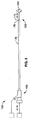
図1中に示される通り、本発明は、外側管状シース40内において同軸的に位置決めされるワイヤ20を有する慢性完全閉塞(CTO)クロスシステム10を有する。ワイヤは、管状シースの遠位端部36を越えて延在する(extending beyond)遠位先端26を有する。管状シース30及びワイヤ20の各々の近位端部22,32は、夫々、ワイヤ20がカプラー54を介してワイヤに対して結合されるモータ52によって機械的にスピンされるよう、アクチュエータ組立体50に対して結合され、また、ワイヤ20が外側管状シース40内においてスピンするようにされる。
As shown in FIG. 1, the present invention includes a chronic total occlusion (CTO)
ワイヤの遠位先端26は、拡張部(enlargement)30を有する。拡張部30は、図1中に示される実施例においては、具体的且つ特に有益であるよう以下の通りに構成及び方向付けられる。拡張部30は、近位端部32と遠位端部36との間において延在する長手方向軸lに沿った長さを有する。拡張部30は、拡大部30が固定されているところのワイヤ20のコア24に対して斜めに位置付けられ、長手方向軸lは、コアワイヤ20の長手方向軸Lに対して角度αを有する。加えて、遠位端部36は、一般的には、長手方向軸Lに沿って中心に揃えられ(centered)、その近位端部32は、長手方向軸Lに対してオフセットされる。したがって、長手方向軸Lの周囲にワイヤをスピンさせることによって、拡張部30は、長手方向軸l及びLが交差する点として遠位端部36の周囲に中心を揃えられた円錐状のパターンの周囲にスピンし、近位端部32において半径に対して外側に向かって近位にテイパする(tapering proximally outward to a radius at proximal end)。この動作は、CTO病変を通る遠位前進(distal advancement)と結合され、組織を半径方向に押し離すよう設計される振動を作り出す。これによって、遠位先端36かはら始まる拡張部30は、望ましくはかかる動作に対して抵抗の少ない経路を見つけ、且つ経路に沿って広がり得る。該動作は、血小板及び固有の血管壁組織、又は血小板及び繊維の血栓等であるCTOにおける少なくとも2つの非晶質組織の間において自然組織平面において最も頻繁に発生すると考えられる。
The
シース40は、内部に収容されるワイヤ20にわたってしっかりと耐え得るよう(tightly toleranced)設計され、シース40及びワイヤ20は、共にCTOを通って前進する。これは、遠位拡張部30が実質的にCTOへと進められ次第、コアワイヤ30を結束させる(bind)CTOの半径方向の圧縮力を外側シース40が担うことを可能にする。かかる外側シース40が無ければ、先端26における意図されるねじり回転は、例えば、脚部において約10センチメートルと同等又はそれを超える長さ、あるいは、約15又は20センチメートルと同等又はそれを超える長さであり得る、実質的に長いCTO病変によって妨害され(compromised)得る、と考えられる。かかる結束(binding)は、力の特定の組合せのもと、且つかかる外側シース40内における半径方向の閉じこめ(radial confinement)を有さず、遠位拡張部30の近くにおいてワイヤ30のコア24上で作られるねじれ張力を更にもたらし得、また、コア24がそれ自体を脱する(core 24 prolapses upon itself)不具合モードをもたらし得る。この事象は、ループが長手方向軸Lに対して横断方向を潜在的に形成する等の、例えば血管におけるワイヤ20の著しいリモデル(remodelling)をもたらし得、実質的に剛性な物質を有するループは近くの血管に対して損傷を与え得る。
The sheath 40 is designed to be tightly tolerated over the wire 20 contained therein, and both the sheath 40 and the wire 20 are advanced through the CTO. This allows the outer sheath 40 to bear the radial compressive force of the CTO that binds the
ワイヤ20及び外側シース40がCTOにわたって成功裏に前進されたあと、外側シース40は、ワイヤ20から近位に取り除かれ得(proximally removed)、血管形成術、ステント、あるいは、アテローム切除術又はアブレーション(図示せず)等の治療装置に対するレールとして作用することができる。あるいは、シース40は、残り得、また同軸レールを与え得る。該同軸レールの上方において、治療装置は、病変まで追跡され(tracked to)、且つ病変をわたる(across)。 After the wire 20 and the outer sheath 40 have been successfully advanced over the CTO, the outer sheath 40 can be removed from the wire 20 proximally (angioplasty, stent, or atherectomy or ablation). It can act as a rail for a treatment device such as (not shown). Alternatively, the sheath 40 can remain and provide a coaxial rail. Above the coaxial rail, the treatment device is tracked to the lesion and crosses the lesion.
図1中に示されるシースワイヤシステム10は、血管系を通る病変まで組立体を進ませるステアリング機構を有さない。これは、遠位先端26が単に病変クロスに対して最適化されるという利点を与える一方、従来のステアリング可能なガイドワイヤのステアリングを強化するよう意図されて形成される遠位先端は、「軸外(”off−axis”)」を指し、病変に対して長手方向遠位に向けられる際、望ましくは血管壁に向かって軸外に進み得る。それにもかかわらず、現在の組立体は、一般的に、蛍光透視誘導下で興味の病変まで進められ、全体的な運搬システム内においてステアリング性能をしばしば備えられる。したがって、更なる一実施例において、別個の運搬シース60(図1中は線で示される)は、まず、第1のガイドワイヤ(図示せず)の上方で病変まで進められ得る。続いて第1のガイドワイヤは、取り除かれ、近くに位置付けられる運搬シース60を通って目標CTO病変に対して追跡する本実施例のシースワイヤ組立体10と置き換えられる。
The
図2は、図1中に示されるものの代替的な設計100を示す。コアワイヤ120及び外側シース140はいずれも、複数の場所においてテイパされ、直径及び剛性における段階的又は漸次的低減を可能にする。近位領域102は、遠位領域108より大きく剛性である中間領域106より、大きく剛性である。このテイパ設計は、屈曲した生体構造及び病変までの、並びにそれらを通る組立体の前進を夫々強化するよう適合される。しかしながら、かかる構成要素の同軸係合がしっかりと許容される(tightly toleranced)場合において、これにより、一般的に、ワイヤ/シース組立体100が病変にわたって進められると、ワイヤ120からの外側シース140の除去が困難になる。したがって、かかる特にしっかりと許容される実施例によれば、続いて運搬される補助的治療装置は、しばしば、シースワイヤ組立体100にわたって同軸に進められる。しかし他の実施例では、夫々の構成要素のテイパされた構造は、続く再開通ツールに対する運搬レールとして露出されたワイヤ120を使用する前に、外側シース140の除去を可能にするよう十分なクリアランスを与え得る。
FIG. 2 shows an
図3は、他の実施例150を示す。ワイヤ160及びシース170は、互いに対して独立して進められ得る。フラッシュルーメン172は、ワイヤ160と外側管状シース170との間における同軸空間に対して与えられ、シース170上の近位止血バルブ180(取外し可能な別個の付属品であり得る)によって、ワイヤ160は、血液の実質的な結合又は損失を有さずに外側シース170内において独立して進められ/スピンされ/引き込まれ得る。これにより、堅いCTO病変を通るワイヤ160及び外側シース170の段階的な独立した前進が可能となり、ワイヤ160のプロファイルは、外側シース170の先端176から遠位に延在される際、著しく低減される。適切な位置付けを行うよう、内側ワイヤ160及び外側シース170の両方の遠位先端範囲166,176は夫々、放射線不透過性マーカーを備えられる。図3はまた、外側シース170に対するワイヤ160の運動(両方向矢印)を作動する多種の近位適合特性を有する近位カプラー筐体156を概略的に示す。また、図面及び本明細書をみることによって当業者にとっては明らかである通り、図3は、液体材料の注入の吸引等に関する筐体156のサイドアームを介する流体連通及びワイヤ駆動構成要素を概略的に示す。
FIG. 3 shows another
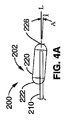
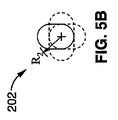
多種の異なる先端構造は、意図される。例えば、図4A中に示される通り、ワイヤ200は、金属ハイポチューブ220内において延在するコアワイヤ210を有し、ハイポチューブ220を近位端部222上でコアワイヤ210に対して一側に押し進めることによって斜めにされ、また、ハイポチューブ220の遠位端部226をコアワイヤ210の長手方向軸Lに沿って実質的に中心にされるよう位置付ける。これは、図4B中の例証的端面図において示される通り、ハイポチューブ220の近位端部が長手方向軸Lに沿って回転の中心軸からオフセットされる距離によって定義付けられる半径R1の周囲に回転の円錐形パターンを示すワイヤ200の遠位先端として、斜めにされた拡張部材202をもたらす。
A variety of different tip structures are contemplated. For example, as shown in FIG. 4A, the
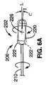
しかしながら、これは、例えば長手方向軸Lに関して低減される半径R2の周囲に回転する、図4A及びB中に示されるより緩やかなわずかな角度Bに沿って、修正され得る。更には、拡張部材202はまた、遠位端部226が長手方向軸Lに沿って位置付けられず、故に軸Lに関する円周パターンに沿って回転するよう、斜めにされ得る。これは、例えば、図6A及びB中に図示される。更には、拡張部材202の角度を斜めにするのではなく、その代わりに回転の長手方向軸Lに対して平行である長手方向軸lを伴ってもよく(may instead entail)、該長手方向軸lは長手方向軸Lから距離D分をオフセットされる。これは、例えば図7中に示される。コアワイヤ210は、ハイポチューブ220の近位及び遠位端部222,224間における1つの壁に対して押し進められる。いずれの場合にも、ハイポチューブ220は、例えば、放射線不浸透性のマーカーと同様であり得、例えば金又はプラチナから構成され、また、近位及び遠位端部222,224においてコアワイヤ210に対してはんだ付け、溶接、接着接合、又は固定され得る。
However, this can be corrected, for example, along a gentler slight angle B shown in FIGS. 4A and B, rotating around a radius R2 that is reduced with respect to the longitudinal axis L. Further, the
コアワイヤ210は、異なる構造を有し得、そのうちの2つの特定の実施例は、例証を目的として図8乃至図11Bにおいて多様に図示される。
The
より具体的には、図8は、以下の通り構成されるワイヤ300を示す。ステンレススチール近位コアワイヤ310は、その遠位端部314においてハイポチューブ320の近位端部322へと固定され、ニッケルチタン超弾性合金を有する遠位コアワイヤ330を更に有する。遠位コアワイヤ330は、遷移ハイポチューブ(transition hypotube)320の遠位端部326内において固定される近位端部332を有し、拡張先端340に対して固定される遠位端部336を有する。1つの有益な形態においては、ハイポチューブ320は、ニッケルチタン合金であり、例えばはんだ付け、溶接、接着接合、スエージ、又は他の適切な既知の方法によって近位及び遠位コアワイヤ310,330に対して固定される。このワイヤ300の実施例の一部の多種の断面図は、更なる例証のために図9A−Dにおいて多様に図示される。
More specifically, FIG. 8 shows a
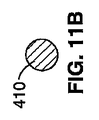
図10は、他の実施例としてスエージされたワイヤ400を示す。ワイヤ400は、ニッケルチタン超弾性合金から構成される内側コアワイヤ410にわたってスエージされるステンレススチール外側ハイポチューブ420を有する。ステンレススチールハイポチューブ420は、ニッケルチタン合金コアワイヤ410のみが拡張先端440が固定されるところである遠位端部416まで延在するよう、終了する。これは、図11A−B中に更に図示される。
FIG. 10 shows a
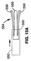
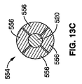
図12は、スピン回転に対してシース/ワイヤ組立体500のワイヤ520の態様を適合させる一実施例を示し、また、以下に記載される近位アダプタ550を示す。近位ワイヤアダプタ550は、遠位突出部552を有する。遠位突出部552は、ねじ山のついた筐体を有して回転し、円周方向に向けられて半径方向にバイアスされる複数の長手方向スプライン556を有するコレット組立体554(図13A参照)にわたって、同軸に前進するよう、あるいは引っ込むようにする。この回転、及び、もたらされるコレット554にわたる長手方向運動は、コレット554を、ワイヤにわたってスプライン556の夫々の半径方向の場所に対応して、半径方向に開放した状態又は閉鎖した状態の間において作動させる。開放及び閉鎖状態におけるコレット554の断面、及びスプライン556の夫々の位置は、夫々図13B−C中に示される。いずれにしてもこれは、近位カプラー550が回転するモータ筐体へと結合され得るよう、並びに、カプラーワイヤのインタフェースにおいて過剰且つ所望されないスリップを有することなく、ワイヤを回転することができるよう、十分な保持力を有して行われる。
FIG. 12 shows one example of adapting the
したがって近位カプラー550は、図14A等において断面で示される通り、モータアクチュエータユニットにおいて係合する同軸筐体600へと挿入される。図14A中の実施例は、以下の通り動作する。外側筐体600は、外側筐体600の回転中にコレットアダプタ550上で機械的に外側リブ558と境を接するリブ602を有する。筐体600を回転することによって、隣接するリブ558,602間の機械的干渉は、コレットカプラー550を外側筐体600とともに回転させる。多くの他の実施例はまた、当業者にとって明らかであるものとして意図及び容認される。例えば、多種の特定の実施例は、図14B−D中に示される。リブ602は、凹部604と多様に置き換えられ、コレットカプラー550の対向する表面上のリブ558は、回転中に干渉を可能にするよう位置付けられる。図14Cは、他の実施例として、構成要素間の対向する関係を示す。例えば、近位カプラー674と外側筐体678との間における方形のキーホール型インタフェースを有するズ14D中に例示されるインタフェース組立体670における、他のキー付き付属品(keyed fittings)もまた、意図される。この種類のインタフェースはまた、近位カプラー674及び内部ワイヤ672のインタフェースに対して適用され得、また方形の形状を有するよう「鋳造(coined)」され得る(図中斜線で示される)。
Accordingly, the
近位カップリングはまた、所望されるトルク量において「屈曲(give)」又は「スリップ」するよう適合され得、先端が堅い病変において立ち往生する際、並びに悪条件での使用中に応力キンク、あるいはワイヤ又は接着の破損等の不具合を引き起こし得る、過剰トルクを防ぐよう安全特性を一般的には考慮されている。かかるスリップを達成する1つの形態は、機械的インタフェース接合部に特定の力レベルにおいて干渉を「もたらし(yield)」、故に中断させる(break)よう制御された性能を与える。これは例えば、与えられた寸法において所望される力において予測通りにもたらされる所望の可撓性を既知の物質を有するリブに与えることによって、達成され得る。図15A−Cは、相互作用するリブが特定の力における機械的「スリップ」中にもたらされる(interfacing ribs are shown under yield during mechanical ”slippage” at a particular force)、モータ筐体に対する近位カップリングが示される。 The proximal coupling can also be adapted to “give” or “slip” at the desired amount of torque, when the tip is stuck in a rigid lesion, as well as during use in adverse conditions, or Safety characteristics are generally considered to prevent excessive torque that can cause defects such as broken wires or bonds. One form of achieving such slip provides a controlled performance to the mechanical interface joint to “yield” and thus break at a specific force level. This can be achieved, for example, by providing the rib with known material with the desired flexibility that is expected to be achieved at the desired force in a given dimension. FIGS. 15A-C show that the interacting ribs are brought into mechanical “slip” at a particular force (proximal coupling to a motor housing). Is shown.
当業者にとって明らかである通り、多種の回転アクチュエータ組立体は、実施例に従って使用され得、例えば、他のクロスするガイドワイヤに対する他の前に開示された回転アクチュエータ、あるいは、前に開示された多種の回転アテローム切除術アクチュエータに類似し得る。したがって、本実施例に対してここで示される回転アクチュエータ組立体は、第一に概略的な形状において与えられ、一般的には、モータドライブユニットに対して結合される回転筐体を有する。しかしながら、図示されない1つの有益な実施例において、ワイヤ近位カプラーと係合される制御された回転筐体は更に、アクチュエータのモータと関連付けられる機械的クラッチ機構に対して結合される。クラッチ機構は、所定の回転抵抗力レベルにおいてスリップするよう機械的に構成され得る。あるいは、電気回路は、例えば特定の速度を保持することに関連付けられる特定の電流、電圧、又は電源レベルにおいて、モータを自動的に切るよう、あるいは、クラッチを作動させるよう、適合され得る。更には、センサーは、回転アクチュエータ組立体において有され得、また、制御ユニットは、モータに対して結合され得、所定の感知された力レベルにおいて、モータを停止するよう、あるいはクラッチを作動させるようプログラムされ得る。 As will be apparent to those skilled in the art, a variety of rotary actuator assemblies may be used in accordance with the embodiments, such as other previously disclosed rotary actuators for other crossing guidewires, or various previously disclosed types. It may be similar to the rotary atherectomy actuator. Accordingly, the rotary actuator assembly shown here for this example is given primarily in schematic form and generally has a rotary housing coupled to the motor drive unit. However, in one beneficial embodiment not shown, the controlled rotating housing engaged with the wire proximal coupler is further coupled to a mechanical clutch mechanism associated with the actuator motor. The clutch mechanism may be mechanically configured to slip at a predetermined rotational resistance level. Alternatively, the electrical circuit can be adapted to automatically turn off the motor or to activate the clutch, for example at a particular current, voltage or power level associated with maintaining a particular speed. Further, a sensor can be included in the rotary actuator assembly, and a control unit can be coupled to the motor to stop the motor or activate the clutch at a predetermined sensed force level. Can be programmed.
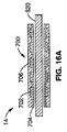
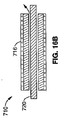
本願中に図示及び記載される多種の態様、形態、及び実施例の外側管状シースの特徴は、多くの異なる構造を有し得、ここで開示されるシステムにおける使用に対して適切であり得る。しかしながら、1つの特定な有益である実施例は、図18A等において示され、外側被覆材(outer jacket material)706内において埋め込まれる内側ライナー704にわたってワイヤ補強702(例えば巻かれたフラットリボン)を有する複合壁700を有する。ライナーは、有益には、シースのルーメン内において回転するワイヤに対して潤滑性がある。該ライナーは、例えば、TEFLON(登録商標)ライナー、高密度ポリエチレン、グラファイトを与えられる高分子ライナー、又は他の適切な潤滑性ライナーであり得る。該ライナーは、最も典型的には、例えば約0.001”乃至約0.005”等であるよう比較的薄く、所望される機能表面に合成物における特徴的役割を十分に与えるよう適切である。外側被覆材706は、例えば内側接着剤を有して、ワイヤ補強材702及び内側ライナー704にわたって縮まる熱収縮物質であり得るか、あるいは、熱可塑性又は熱硬化性であり得、外側表面上へと溶解又は浸漬被覆され得る。例には、ポリエチレン、ナイロン、PEBAX(登録商標)、ポリウレタン、ポリイミド、ポリアミド、ポリオレフィン共重合体、又は技術的に既知である他の適切な物質が有される。遠位に低減された剛性を有する更なる実施例では、構造は、例えば材料を遠位により可撓性のある種類に次第に変えること、補強材遷移のピッチ、寸法、又は材料を変えること、又は、テイパされた設計を与えることによって、シースの長さにわたって変化し得る。補強材702は、超弾性状態にあるニッケルチタン合金等であり得る、巻かれた補強リボンを有し得る。1つの有益な実施例において、かかる超弾性リボンは、堅いCTO病変内において半径方向の力を受ける間、あるいは屈曲中に、楕円形化するよう抵抗を高めるよう、巻かれた構造における記憶状況(memory state)を有するよう処理又は「訓練」される。あるいは、病変における力のもとでつぶれることに抵抗するようより大きな剛性を一般的には有するステンレススチールリボンは、使用され得る。他の金属のリボン、円形ワイヤ、あるいは、ナイロン又はKEVLAR(登録商標)繊維等である他の適切な材料又は構造は、シース補強材に対して使用され得るが、ナイロン又はKEVLAR(登録商標)等の大変柔軟性のある繊維は、半径方向のつぶれ又は楕円形かに対する抵抗に関しては有益ではないと考えられる。
The features of the outer tubular sheath of the various aspects, configurations, and examples illustrated and described herein can have many different configurations and can be suitable for use in the systems disclosed herein. However, one particular beneficial embodiment is shown in FIG. 18A and the like, and has a wire reinforcement 702 (eg, a wound flat ribbon) over an
更なる有益な実施例は、図16B中に示される。シース710は、外側潤滑性コーティング716を有する。該コーティングは、内側回転ワイヤ720の前進と併せてあるいは独立して、運搬シース(図示せず)を通って病変まで、及び/又は堅いCTO病変を通る、外側シース710の前進を支援するよう適合される。適切なコーティングは、ヒドロゲル等である親水性のコーティングを有し得るか、あるいは、シリコンコーティング調整品が使用され得る。他のコーティング材料は、当業者に明らかな通り与えられ得、例えば、血栓溶解コーティング、ヘパリン、ヒルジン、TPA、ストレプトキナーゼ、ウロキナーゼ又は同様のものを有し得る。かかる特定の種類のコーティングは、CTO病変をクロスする性能を支援し得、最終真ルーメンにおける閉塞クロットの残留が病変を通る道を開く助けをするよう、分解され得る。更には、かかる剤は、クロス組立体を通って運搬され得、例えば回転遠位ワイヤ先端(太い矢印)の近くにおける内側ワイヤと外側シースとの間の同軸空間を通って運搬され得る。
A further useful embodiment is shown in FIG. 16B.
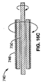
本発明の一実施例の外側シース特徴に対する他の外部処置及び構造はまた、更なる実施例として意図される。例えば、外側表面746は、図16C中に示される通り適切に研磨的にされ得、堅いCTOを通る軸方向前進中に、取り囲む組織を破壊するよう助け得る。あるいは、かかる研磨は、以下に記載される通り、例えば内側ワイヤ730と共にあるいは別個にCTO病変内において外側シース74をスピンさせることによって、シースワイヤ組立体730を堅く取り囲むCTOの組織をアブレーションするよう使用され得る。
Other external treatments and structures for the outer sheath feature of one embodiment of the present invention are also contemplated as further embodiments. For example, the
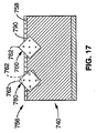
いずれにしても、研磨コーティング756を有する外側層の1つの特定な例は、図17中に半径方向断面の分解詳細において示される。この例証的な実施例は、シース750の外側コーティング層756の外側表面758内において部分的に埋め込まれるダイヤモンド粒子760を有し、該粒子は、適所に固定され、表面758から外方向に延在する鋭い先端762を有する。これは、例えば外側層756が外側シース740へと熱溶解あるいは溶媒ディッピングされたばかりである際に、ダイヤモンドチップの粉末調整品に対して外側表面758をスパッタリングあるいは露出することによって行われる。硬化時には、多種のダイヤモンド粒子760は、多種の向きにおいて固定され、その内の1つは、図17の実施例において例示される。適切に柔らかい外側層の高分子材料内において埋め込まれるダイヤモンド760を与えることによって、アブレーションの機械力下でもたらすことができ(they are also able to yield undermechanical force of ablation)、切断エッジの角度を効果的に低減し、故にそのアブレーティブ効果を和らげ、アブレーションの結果においてもたらされる表面をより潤滑にすると考えられる。例えば、弾性コーティングにおける研磨材料は、ピストン筐体の内側ボア等である、商業的な適用における他の表面を微小ポリッシュする際に使用されるよう、前に開示されており、硬い表面上での研磨を使用する他の技術によって達成され得るものより更に細かい表面仕上げが観察される。
In any event, one particular example of an outer layer having an
前述された多種のシース構造及びコーティングは、典型的なものであり、多様に組み合わせられ得るか、あるいは修正され得、他の外側構造及び材料にも置き換えられ得る。かかる更なる一実施例は、外側層壁材料へと研磨材料を埋め込むのではなく、シースの外側被覆層の外側表面上へと研磨材料を結合させるよう接着剤又は他の接合層材料を使用する。前述された実施例の他の有益な組合せは、図17中に更に示される通り、研磨粒子760と共に潤滑性の外側コーティング790を有するシース740によって図示される。例えば、研磨粒子760が外側シース層756の外側表面758上にコーティングされた後、あるいはそこに部分的に埋め込まれた後、潤滑性コーティング層790は適用され得る。更なる1つの変形においては、潤滑性コーティングは、ダイヤモンド粒子に接合せず、研磨粒子間における外側管表面上へとコーティングされ、そこに接合され得る。この組合せは、外側表面を有してアブレーションする性能を可能にし、また、CTO病変物質にわたって動くよう、並びに該物質を通って動くよう、外側シースに対して高められた潤滑性を与えることを可能にする。
The various sheath structures and coatings described above are exemplary and can be variously combined or modified and replaced with other outer structures and materials. One such embodiment uses an adhesive or other bonding layer material to bond the abrasive material onto the outer surface of the outer sheath layer of the sheath, rather than embedding the abrasive material into the outer layer wall material. . Another beneficial combination of the embodiments described above is illustrated by a
外側シースが取り囲むCTO病変組織の回転アブレーションに対して使用される際、ポートは、外側シースと内側ワイヤとの間の同軸空間へと与えられ得る。該空間は、アブレーションされた材料を吸引除去するよう真空源に対して結合され得る。かかる配置の1つの例は、図18A中に示される。溝をつけられたポート820は、外側シース810の高分子壁814を通って形成されるが、補強ワイヤ812はそのまま残される。これは、損なわれていない補強部材812により管状壁の完全性(integrity)の実質的な損失を有さず、また、回転中に近接するブロック組織(blockage tissue)の幅の長さを測る(span)ことができる溝付きポート820に沿って実質的に連続する直線吸引範囲を可能にする。これは、例えば、高分子が溝の線に沿ってアブレーションされる特定の周波数を有するレーザー光を使用して行われ得る。あるいは、別個のポート840は、図18B中に示される通り、補強リボンの近接する巻き(winds)間の空間に沿って形成され得る。あるいは、外側シースは、補強リボン等を有し得ず、ポート配置は、巻きの間において位置決めされるよう正確である必要はない。
When used for rotational ablation of the CTO lesion tissue that the outer sheath surrounds, the port may be provided into a coaxial space between the outer sheath and the inner wire. The space can be coupled to a vacuum source to suck away ablated material. One example of such an arrangement is shown in FIG. 18A. A slotted
上述された通り、本願中に図示及び説明される多種の態様、形態及び実施例の外側シースの特性は、CTOをクロスする総括的機能システム及び方法において外側シースと協働する夫々の内側ワイヤの特性を有して、あるいは有さず、回転され得る。ワイヤ920及び外側シース940を回転させるようアクチュエータ組立体910を有する1つの典型的なシステム900は、図19中に概略的に示される。ここでは、近位アクチュエータ組立体910は、夫々回転カプラー913,915を介して別個にワイヤ920及び外側シース940を回転させる、第1及び第2のモータ912,914を有する。アクチュエータ組立体910内におけるかかるモータ駆動回転カプリングは、同一の速度及び方向において回転され得る。あるいは、かかるカップリングは、図中斜線矢印で示される通り、対向する方向において回転され得る。吸引ポート956は、概略的に図示される通り、アブレーションからの破片を取り除くよう、ワイヤ920と外側シース940との間における同軸空間950に対して結合され得る。このポート956及び流路950はまた、上述された通り、生体活性剤の運搬に対して使用され得る(あるいは、追加的な流体連絡ルーメンは、吸引及び流体運搬特性を与えるよう与えられ得る)。
As noted above, the characteristics of the outer sheath of the various aspects, configurations and examples illustrated and described herein are the characteristics of each inner wire that cooperates with the outer sheath in an overall functional system and method that crosses the CTO. Can be rotated with or without properties. One
シースが半径方向に取り囲むブロック組織を回転式にアブレーションし得るようにすることによって、例えば特には長い病変を通る追加的な前進に対する抵抗は、低減される。加えて、パイロットホールは、病変を通るよう作られ、のちに血管形成術バルーン、ステント組立体、又はアテローム切除術組立体等の他の治療装置をCTO病変を通って運搬する性能を支援し得る。これは特に、シースがその後適所に残された内側ワイヤを有して除去され得る実施例に対して有用であり、治療装置は、治療に対してパイロットホールを通ってワイヤにわたって置き換えられる。これはまた、特には脚(大腿動脈、SFA等)において、末梢脈管構造における比較的長いCTO病変の場合に有用であり得る。例えば、適切に選択された外径を有する外側シースに対して、アブレーションされたパイロット流路は、そこに位置付けられる治療装置のプロファイルと略同等であり得るか、僅かにそれより大きい。したがって、ここに記載される外側シース/ワイヤ組立体を有するキットが、CTO組立体によって形成されるべきパイロットホールにおいてその後使用されるよう選択される治療装置と共に与えられる、ことは更に意図される。 By allowing rotational ablation of the block tissue radially surrounded by the sheath, the resistance to additional advancement, for example, particularly through long lesions, is reduced. In addition, the pilot hole can be made to pass through the lesion and later support the ability to carry other treatment devices such as angioplasty balloons, stent assemblies, or atherectomy assemblies through the CTO lesion. . This is particularly useful for embodiments where the sheath can then be removed with the inner wire left in place, and the treatment device is replaced over the wire through the pilot hole for treatment. This can also be useful in the case of relatively long CTO lesions in the peripheral vasculature, especially in the legs (femoral artery, SFA, etc.). For example, for an outer sheath having a suitably selected outer diameter, the ablated pilot flow path may be approximately equivalent to or slightly larger than the profile of the treatment device positioned therein. Accordingly, it is further contemplated that a kit having an outer sheath / wire assembly as described herein is provided with a treatment device selected for subsequent use in a pilot hole to be formed by the CTO assembly.
また、外側シースを有する回転アブレーションは、シース/ワイヤ組立体が病変を通って前進し続けるため、病変の近位に位置決めされる外側シースの大部分を有して開始し得る、ことは予期される。したがって、第2の外側保護被覆物は、第1の外側シースにわたって与えられ得、スピン組立体の近位研磨外側表面から近位血管壁を保護するよう病変に対して近位に位置付けられ得る。 It is also anticipated that rotational ablation with an outer sheath may begin with the majority of the outer sheath positioned proximal to the lesion as the sheath / wire assembly continues to advance through the lesion. The Thus, a second outer protective coating can be provided over the first outer sheath and positioned proximal to the lesion to protect the proximal vessel wall from the proximal polished outer surface of the spin assembly.
本願は、CTO病変の治療に対するシステム、組立体、又は装置に関する実施例を記載する。かかる実施例の構成要素の組合せが大変有益である一方、例えば他の構成要素とのちに相互に作用するよう別個に作られる及び/又は販売される可能性により、各個別の構成要素単独でも大変有益であることが意図される。更には、多種の実施例が最初にCTO病変にわたって、また固有の下流血管ルーメンへと、ガイドレールを置く機能を与える範囲において、かかる実施例は、再開通又は他の治療を実行し得る機構を与える範囲までの「治療」システム又は組立体を検討する。 This application describes embodiments relating to systems, assemblies or devices for the treatment of CTO lesions. While the combination of the components of such an embodiment is very beneficial, each individual component alone is also very large, for example due to the possibility of being made and / or sold separately to interact with other components. It is intended to be beneficial. Furthermore, to the extent that various embodiments provide the ability to place a guide rail over the CTO lesion initially and into the unique downstream vessel lumen, such embodiments provide a mechanism that can perform reopening or other treatments. Consider a “treatment” system or assembly to the extent given.
本発明は、特定の望ましい実施例に関して記載されてきた。当業者は、多種の修正が本発明の範囲から逸脱することなくなされ得る、ことを認識する。CTO病変をクロス及び治療することに関してまず記載されてきたが、実施例は、他の適用に対しても使用され得ることが理解されるべきである。他の適用とは、例えば、CTOと判断されない他の血管ブロック、又は他の体ルーメン又は空間におけるブロックである。加えて、特定の協働する、あるいは補助する治療又は他の付属装置が、実施例と共に使用に対して記載されるが、他の修正は、当業者にとって明らかである通り意図される。更には、特定の特徴が特定の実施例と関連して図示又は説明され得る一方、かかる個別の特性は、本発明の多種の他の実施例においても使用され得る。 The invention has been described with reference to certain preferred embodiments. Those skilled in the art will recognize that various modifications can be made without departing from the scope of the present invention. Although first described with respect to crossing and treating CTO lesions, it should be understood that the examples may be used for other applications. Other applications are, for example, other vascular blocks that are not considered CTO, or blocks in other body lumens or spaces. In addition, although specific cooperating or ancillary treatments or other accessory devices are described for use with the examples, other modifications are contemplated as will be apparent to those skilled in the art. Further, while specific features may be illustrated or described in connection with specific embodiments, such individual characteristics may be used in various other embodiments of the invention.
Claims (44)
カテーテルアクチュエータと、
該カテーテルアクチュエータによって作動されるよう構成され、近位端部と、遠位端部と、近位ポートと前記遠位端部において位置決めされる遠位ポートとの間に延在するガイドワイヤルーメンとを有する第1の細長いボディを有する、カテーテルと、
ワイヤクチュエータと、
該ワイヤクチュエータによって作動されるよう構成され、近位端部と、第1の長手方向軸及び第1の外径を有する遠位端部と、該第1の外径に対して半径方向に拡張される第2の外径を有する前記遠位端部上の遠位先端部分とを有する第2の細長いボディを有する、ガイドワイヤと、
を有し、
前記カテーテルは、クロス構造における前記ガイドワイヤを、前記ガイドワイヤルーメン内において、並びに前記遠位ポートを遠位に越える前記ガイドワイヤルーメンの外部に位置決めされる前記拡張された遠位先端部分を有する前記遠位ポート及び近位ポートを通って延在する、前記ガイドワイヤと可動的に係合するよう適合され、
作動カテーテル及び作動ガイドワイヤは、前記クロス構造において実質的に共に前記CTOにわたって前進するよう構成される、
医療装置システム。 A medical device system that provides vascular access over chronic total occlusion (CTO) comprising:
A catheter actuator;
A guide wire lumen configured to be actuated by the catheter actuator and extending between a proximal end, a distal end, and a proximal port and a distal port positioned at the distal end; A catheter having a first elongate body having:
Wire actuators,
Constructed to be actuated by the wire actuator and having a proximal end, a distal end having a first longitudinal axis and a first outer diameter, and radially extending relative to the first outer diameter A guide wire having a second elongate body having a distal tip portion on the distal end having a second outer diameter to be
Have
The catheter has the expanded distal tip portion positioned within the guidewire lumen in a cross structure, within the guidewire lumen, and external to the guidewire lumen that extends distally beyond the distal port. Adapted to movably engage the guidewire extending through the distal and proximal ports;
An actuating catheter and an actuating guidewire are configured to advance across the CTO substantially together in the cross structure;
Medical device system.
近位端部と、ワイヤ補強高分子壁を有する遠位端部と、近位ポートと前記遠位端部において位置決めされる遠位ポートとの間に延在するガイドワイヤルーメンとを有する第1の細長いボディを有する、カテーテルと、
ワイヤクチュエータと、
近位端部と、第1の長手方向軸を有する遠位端部と、前記遠位端部上の遠位先端部分とを有する第2の細長いボディを有し、前記ワイヤアクチュエータによって作動されるよう適合される、ガイドワイヤと、
を有し、
前記カテーテルは、クロス構造における前記ガイドワイヤを、前記ガイドワイヤルーメン内において、並びに前記遠位ポートを遠位に越える前記ガイドワイヤルーメンの外部に位置決めされる前記遠位先端部分を有する前記遠位ポート及び近位ポートを通って延在する、前記ガイドワイヤと可動的に係合するよう適合され、
前記カテーテル及び前記作動ガイドワイヤは、前記作動ガイドワイヤの前記遠位端部上へと前記CTOの半径方向の結束を阻むよう構成される前記カテーテルの前記ワイヤ補強遠位端部を有し、前記クロス構造において実質的に共に前記CTOにわたって前進するよう構成される、
医療装置システム。 A medical device system that provides vascular access over chronic total occlusion (CTO) comprising:
A first end having a proximal end, a distal end having a wire reinforced polymer wall, and a guidewire lumen extending between the proximal port and a distal port positioned at the distal end. A catheter having an elongated body of
Wire actuators,
A second elongate body having a proximal end, a distal end having a first longitudinal axis, and a distal tip portion on the distal end is actuated by the wire actuator A guide wire, adapted to
Have
The catheter has the distal tip portion positioned with the guidewire in a cross structure, within the guidewire lumen, and external to the guidewire lumen that extends distally beyond the distal port. And adapted to movably engage the guidewire extending through the proximal port;
The catheter and the working guidewire have the wire reinforced distal end of the catheter configured to prevent radial binding of the CTO onto the distal end of the working guidewire; Configured to advance over the CTO substantially together in a cross structure,
Medical device system.
第1の近位端部と、第1の遠位端部とを有する第1の細長いボディを有するカテーテルを有する、第1の機械的に作動される装置と、
第2の近位端部と、第2の遠位端部とを有する第2の細長いボディを有するカテーテルを有する、第2の機械的に作動される装置と、
を有し、
ルーメンは、近位ポートと前記遠位端部における遠位ポートとの間における前記第1の作動装置内において延在し、
前記第2の作動装置は、運搬構造において前記遠位ポートを通り前記ルーメンから延在する前記第2の遠位ポートを有する前記ルーメン内において少なくとも部分的に位置決めされ、
前記運搬構造において、前記第1及び第2の遠位端部は、夫々前記患者の外部に延在する前記第1及び第2の近位端部を有して前記患者の体内における場所まで抵抗をわたって送られるよう適合される、
医療装置システム。 A medical device system for performing a medical procedure related to a medical condition in a patient's body,
A first mechanically actuated device having a catheter having a first elongate body having a first proximal end and a first distal end;
A second mechanically actuated device having a catheter having a second elongate body having a second proximal end and a second distal end;
Have
A lumen extends within the first actuator between a proximal port and a distal port at the distal end;
The second actuator is positioned at least partially within the lumen having the second distal port extending from the lumen through the distal port in a delivery structure;
In the delivery structure, the first and second distal ends each have the first and second proximal ends extending outside the patient and resist to a location in the patient's body. Adapted to be sent across,
Medical device system.
近位端部と、遠位端部と、前記遠位端部において遠位ポートを有するガイドワイヤルーメンとを有する第1の細長いボディを有する、カテーテルと、
近位端部と、第1の外径を有する第1の長手方向軸に沿って延在する遠位端部とを有する第2の細長いボディを有する、ガイドワイヤと、
前記ガイドワイヤの前記遠位端部上に位置決めされる遠位先端部分と、
を有し、
前記遠位先端部分は、第2の外径と、近位端部と遠位端部との間において第2の長手方向軸に沿った長さと、を有し、
前記第2の長手方向軸は、前記第1の長手方向軸に対して角度をなされ、
前記第2の外径は、前記第1の外径より大きく、前記遠位先端部分が前記第2の細長いボディの前記遠位端部に対して半径方向に拡張され、
前記ガイドワイヤの前記第2の細長いボディは、前記遠位ポートから遠位に前記ガイドワイヤルーメンの外部に延在される前記ガイドワイヤの前記遠位先端部分を有するクロス構造において少なくとも部分的に前記ガイドワイヤルーメン内において回転可能に配置されるよう構成され、
前記ガイドワイヤは、前記患者の身体の外部での前記近位端部の回転時にトルク可能であり、前記ガイドワイヤの遠位端部の前記長手方向軸の周囲に前記遠位先端部分を回転させるよう、十分なトルクが前記患者の体内におけるCTO位置において前記遠位先端部分に対して伝達され、
前記第1の細長い管状ボディの前記遠位端部及び前記ガイドワイヤは、前記クロス構造において前記CTOにわたって協調される前進において協働するよう適合され、
前記第1の細長い管状ボディの前記遠位端部は、前記クロス構造における前記CTOを通る前記第1の細長い管状部材の前記遠位端部及び前記ガイドワイヤの前記協調される前進中に、前記ガイドワイヤ近位端部から前記遠位先端部分までのトルク伝達における前記CTOからの抵抗を実質的に阻止するよう、構成される、
医療装置システム。 A medical device system that provides vascular access over a chronic total occlusion ("CTO") in a patient's body, comprising:
A catheter having a first elongate body having a proximal end, a distal end, and a guidewire lumen having a distal port at the distal end;
A guidewire having a second elongate body having a proximal end and a distal end extending along a first longitudinal axis having a first outer diameter;
A distal tip portion positioned on the distal end of the guidewire;
Have
The distal tip portion has a second outer diameter and a length along a second longitudinal axis between the proximal end and the distal end;
The second longitudinal axis is angled with respect to the first longitudinal axis;
The second outer diameter is greater than the first outer diameter and the distal tip portion is radially expanded relative to the distal end of the second elongate body;
The second elongate body of the guidewire is at least partially in a cross structure having the distal tip portion of the guidewire extending distally from the distal port and out of the guidewire lumen. Configured to be rotatably disposed within the guidewire lumen;
The guidewire is torqueable upon rotation of the proximal end outside the patient's body and rotates the distal tip portion about the longitudinal axis of the distal end of the guidewire Sufficient torque is transmitted to the distal tip portion at a CTO location in the patient's body,
The distal end of the first elongate tubular body and the guidewire are adapted to cooperate in a coordinated advance across the CTO in the cross structure;
During the coordinated advancement of the distal end of the first elongate tubular member and the guidewire through the CTO in the cross structure, the distal end of the first elongate tubular body Configured to substantially prevent resistance from the CTO in torque transmission from the proximal end of the guidewire to the distal tip portion;
Medical device system.
近位端部と、長手方向軸に沿って長さを有する遠位端部と、前記遠位端部に少なくとも部分的に沿ってガイドワイヤを可動に係合するよう適合されるガイドワイヤルーメンと、前記近位端部に沿った近位ポートと前記遠位端部における遠位ポートとの間に延在する吸引ルーメンと、を有する第1の細長い管状ボディを有する、カテーテル、
を有し、
前記遠位端部は、高分子壁と結合されるワイヤの離間部分と、前記長手方向軸の周りの円周に沿って位置決めされる外側表面とを有する、ワイヤ補強高分子合成管状部材を有し、
前記近位端部は、アブレーションアクチュエータに対して結合するよう適合されるアブレーションカプラーを有し、
前記合成管状部材は、前記アブレーションカプラーに対して結合されるアブレーションアクチュエータによる作動時に、前記外側表面と接触するCTO組織をアブレーションするよう適合され、
前記遠位ポートは、前記遠位先端の近位に、前記ワイヤ補強高分子合成管状部材のワイヤの前記離間部分の間における高分子壁を通って位置決めされ、
前記近位ポートは、真空源に対して結合されるよう適合される真空カプラーを有し、
作動される真空源に対して前記真空カプラーを結合することによって、十分な吸引が前記管状部材によってアブレーションされるCTO組織の破片を取り除くよう前記遠位ポートにおいて適用される、
医療装置システム。 A medical device system that provides vascular access over a chronic total occlusion ("CTO") in a patient's body,
A proximal end, a distal end having a length along a longitudinal axis, and a guidewire lumen adapted to movably engage a guidewire at least partially along the distal end A catheter having a first elongate tubular body having a proximal lumen along the proximal end and a suction lumen extending between the distal port at the distal end.
Have
The distal end includes a wire reinforced polymer synthetic tubular member having a spaced apart portion of the wire coupled to a polymer wall and an outer surface positioned along a circumference about the longitudinal axis. And
The proximal end has an ablation coupler adapted to couple to an ablation actuator;
The synthetic tubular member is adapted to ablate CTO tissue in contact with the outer surface upon actuation by an ablation actuator coupled to the ablation coupler;
The distal port is positioned proximal to the distal tip through a polymer wall between the spaced portions of the wire of the wire-reinforced polymer synthetic tubular member;
The proximal port has a vacuum coupler adapted to be coupled to a vacuum source;
Sufficient aspiration is applied at the distal port to remove debris of CTO tissue ablated by the tubular member by coupling the vacuum coupler to an actuated vacuum source;
Medical device system.
近位端部と、長手方向軸に沿ってルーメンを定義する内側表面及び前記長手方向軸を取り囲む円周に沿って位置決めされる研磨外側表面を有する管状部材を有する遠位端部と、前記管状部材の前記ルーメンを少なくとも部分的に通って延在して定義されるガイドワイヤ通路とを有する第1の細長い管状ボディを有する、カテーテル、
を有し、
近位端部は、回転アブレーションアクチュエータに対して結合されるよう適合されるアブレーションカプラーを有し、
前記第1の細長い管状ボディは、十分にトルク可能であり、前記患者の身体の外部に位置決めされる回転アブレーションアクチュエータを有して近位端部を回転させることによって前記患者の体内におけるCTO内において前記管状部材が回転可能であるようにし、
前記CTO内において前記管状部材を回転させることによって、前記研磨外側表面は、前記CTOを通る前進において前記カテーテルを支援するよう十分に接触するCTO組織を機械的にアブレーションするよう適合される、
医療装置システム。 A medical device system that provides vascular access over a chronic total occlusion ("CTO") in a patient's body, comprising:
A distal end having a proximal end and a tubular member having an inner surface defining a lumen along a longitudinal axis and an abrasive outer surface positioned along a circumference surrounding the longitudinal axis; and the tubular A catheter having a first elongate tubular body having a guidewire passage defined extending at least partially through the lumen of the member;
Have
The proximal end has an ablation coupler adapted to be coupled to a rotary ablation actuator;
The first elongate tubular body is sufficiently torqueable and has a rotary ablation actuator positioned external to the patient's body and within the CTO in the patient's body by rotating the proximal end. The tubular member is rotatable,
By rotating the tubular member within the CTO, the abrasive outer surface is adapted to mechanically ablate CTO tissue that is in sufficient contact to assist the catheter in advancement through the CTO.
Medical device system.
近位端部と、長手方向軸に沿い且つ遠位先端において終了する長さを有する遠位端部と、前記近位端部に沿った近位ポートと前記遠位端部に沿った遠位ポートとの間に延在する通路とを有する第1の細長い管状ボディを有する、カテーテル、
を有し、
前記遠位ポートは、前記遠位先端の近位に、前記細長い管状ボディを通って位置決めされ、
前記近位ポートは、真空圧力の源に対して結合されるよう適合される近位カプラーを有し、
前記近位ポートは、前記遠位ポートに対して流体的に結合され、作動される真空圧力の源に対して前記近位ポートを結合させる際、吸引が前記遠位ポートにおいて適用されるようにし、
前記近位端部は更に、エネルギー源に対して結合するよう適合されるアブレーションカプラーを有し、
前記遠位端部は更に、前記アブレーションカプラーに対して結合されるアブレーション組立体を有し、
前記アブレーション組立体は、前記アブレーションカプラーに対して結合されるエネルギー源によって作動されるよう適合され、前記通路内において位置決めされる軟組織へと十分なエネルギーを放射し、前記通路の外部に位置決めされる他の組織を実質的にアブレーションすることなく前記組織をアブレーションする、
医療装置システム。 A medical device system for removing soft tissue from a body space in a patient,
A proximal end; a distal end having a length along the longitudinal axis and ending at the distal tip; a proximal port along the proximal end; and a distal along the distal end A catheter having a first elongate tubular body having a passage extending between the ports;
Have
The distal port is positioned through the elongated tubular body proximal to the distal tip;
The proximal port has a proximal coupler adapted to be coupled to a source of vacuum pressure;
The proximal port is fluidly coupled to the distal port so that suction is applied at the distal port when coupling the proximal port to a source of vacuum pressure to be actuated. ,
The proximal end further comprises an ablation coupler adapted to couple to an energy source;
The distal end further comprises an ablation assembly coupled to the ablation coupler;
The ablation assembly is adapted to be actuated by an energy source coupled to the ablation coupler, emits sufficient energy to soft tissue positioned within the passage, and is positioned outside the passage. Ablating the tissue without substantially ablating other tissue,
Medical device system.
前記外側表面に沿って与えられる複数の研磨粒子と、
を有し、
前記研磨粒子の各々は、前記外側表面の下方の前記エラストマ材料内に埋め込まれる第1の部分と、前記外側表面から前記エラストマ材料の上方に延在する第2の部分とを有し、
前記患者の体内における動作へと前記遠位端部を作動させることによって、前記研磨粒子は、前記外側表面と接触する組織を機械的にアブレーションするよう構成される、
医療装置システム。 A proximal end, a distal end adapted to be positioned within the patient's body with the proximal end extending outwardly from the patient, and an outer surface and elastomer along the distal end A first elongate body having a wall with material;
A plurality of abrasive particles provided along the outer surface;
Have
Each of the abrasive particles has a first portion embedded in the elastomeric material below the outer surface and a second portion extending from the outer surface and above the elastomeric material;
By actuating the distal end into motion within the patient's body, the abrasive particles are configured to mechanically ablate tissue in contact with the outer surface.
Medical device system.
遠位先端部分は、前記ガイドワイヤの前記遠位端部上に位置決めされる、
請求項3記載のシステム。 The second mechanically actuated device includes a proximal end at least partially having a second proximal end and a distal end at least partially having the second distal end. A guidewire having a second elongate body having a first outer diameter and extending along a first longitudinal axis having a first outer diameter;
A distal tip portion is positioned on the distal end of the guidewire;
The system of claim 3.
を更に有する、
請求項5記載のシステム。 A first end having a proximal end, a distal end extending along a first longitudinal axis having a first outer diameter, and a distal tip portion on the distal end of the guidewire; A guide wire having two elongated bodies;
Further having
The system of claim 5.
を更に有する、
請求項6記載のシステム。 A first end having a proximal end, a distal end extending along a first longitudinal axis having a first outer diameter, and a distal tip portion on the distal end of the guidewire; A guide wire having two elongated bodies;
Further having
The system according to claim 6.
を更に有する、
請求項7記載のシステム。 A first end having a proximal end, a distal end extending along a first longitudinal axis having a first outer diameter, and a distal tip portion on the end of the guidewire; A guide wire having two elongated bodies;
Further having
The system of claim 7.
を更に有する、
請求項8記載のシステム。 A first end having a proximal end, a distal end extending along a first longitudinal axis having a first outer diameter, and a distal tip portion on the end of the guidewire; A guide wire having two elongated bodies;
Further having
The system of claim 8.
請求項13記載のシステム。 The second elongate body further comprises a catheter having a lumen extending between a proximal port and a distal port at the distal portion.
The system of claim 13.
前記ガイドワイヤの前記第2の細長いボディは、前記遠位端部から遠位に前記ガイドワイヤルーメンの外部に延在される前記ガイドワイヤの前記遠位先端部分を有するクロス構造において少なくとも部分的に前記ガイドワイヤルーメン内において回転可能に配置されるよう構成され、
前記ガイドワイヤは、十分にトルク可能であり、前記患者の身体の外部での前記近位端部の回転時に、前記患者の体内におけるCTO位置において前記遠位先端部分に対して十分なトルクが伝達され、前記ガイドワイヤの遠位端部の前記長手方向軸の周囲に前記遠位先端部分を回転させ、
前記第1の細長い管状ボディ及び前記ガイドワイヤは、前記クロス構造において前記CTOにわたる協調された前進において協働するよう適合される、
請求項1記載のシステム。 The second longitudinal axis is angled with respect to the first longitudinal axis;
The second elongate body of the guidewire is at least partially in a cross structure having the distal tip portion of the guidewire extending outward from the guidewire lumen distally from the distal end. Configured to be rotatably disposed within the guidewire lumen;
The guidewire is sufficiently torqueable so that sufficient torque is transmitted to the distal tip portion at the CTO position within the patient's body during rotation of the proximal end outside the patient's body. Rotating the distal tip portion about the longitudinal axis of the distal end of the guidewire;
The first elongate tubular body and the guidewire are adapted to cooperate in coordinated advancement over the CTO in the cross structure;
The system of claim 1.
請求項15記載のシステム。 The first elongate tubular member is in torque transmission from the guidewire proximal end to the distal tip portion during coordinated advancement of the guidewire and elongate tubular member through the CTO in the cross structure. Configured to substantially prevent resistance of the CTO;
The system of claim 15.
前記第2の長手方向軸は、前記第1の長手方向軸に対して角度を成し、
前記第2の外径は、前記第1の外径より大きく、前記遠位先端部分が前記ガイドワイヤの前記第2の細長いボディの前記遠位端部に対して拡張され、
前記ガイドワイヤの前記第2の細長いボディは、前記遠位端部から遠位に前記ガイドワイヤルーメンの外部に延在される前記ガイドワイヤの前記遠位先端部分を有するクロス構造において少なくとも部分的に前記ガイドワイヤルーメン内において回転可能に配置されるよう構成され、
前記ガイドワイヤは、十分にトルク可能であり、前記患者の身体の外部での前記近位端部の回転時に、前記患者の体内におけるCTO位置において前記遠位先端部分に対して十分なトルクが伝達され、前記ガイドワイヤの遠位端部の前記長手方向軸の周囲に前記遠位先端部分を回転させ、
前記第1の細長い管状ボディ及び前記ガイドワイヤは、前記クロス構造において前記CTOにわたる協調された前進において協働するよう適合される、
請求項2,9,10,11,12又は13記載のシステム。 The distal tip portion has a second outer diameter and a length along a second longitudinal direction between the proximal end and the distal end;
The second longitudinal axis is angled with respect to the first longitudinal axis;
The second outer diameter is greater than the first outer diameter and the distal tip portion is expanded relative to the distal end of the second elongate body of the guidewire;
The second elongate body of the guidewire is at least partially in a cross structure having the distal tip portion of the guidewire extending outward from the guidewire lumen distally from the distal end. Configured to be rotatably disposed within the guidewire lumen;
The guidewire is sufficiently torqueable so that sufficient torque is transmitted to the distal tip portion at the CTO position within the patient's body during rotation of the proximal end outside the patient's body. Rotating the distal tip portion about the longitudinal axis of the distal end of the guidewire;
The first elongate tubular body and the guidewire are adapted to cooperate in coordinated advancement over the CTO in the cross structure;
The system according to claim 2, 9, 10, 11, 12 or 13.
請求項17記載のシステム。 The first elongate tubular member is in torque transmission from the guidewire proximal end to the distal tip portion during coordinated advancement of the guidewire and elongate tubular member through the CTO in the cross structure. Configured to substantially prevent resistance of the CTO;
The system of claim 17.
請求項1,2,4,9,10,11,12又は13記載のシステム。 Each of the guidewire and catheter is coupled to a rotary actuator;
14. A system according to claim 1, 2, 4, 9, 10, 11, 12, or 13.
請求項18記載のシステム。 Each of the guidewire and catheter is rotationally operated independently of the other,
The system of claim 18.
請求項1,2,4,9,10,11,12又は13記載のシステム。 The distal tip portion of the guidewire comprises a radiopaque material;
14. A system according to claim 1, 2, 4, 9, 10, 11, 12, or 13.
前記ガイドワイヤの前記遠位先端部分の前記近端部は、前記第1の長手方向軸からオフセットされ、
前記ガイドワイヤの回転時に、前記遠位先端部分の前記半径方向にオフセットされた近位端部は、半径Rの周囲に前記第1の長手方向軸の周りに回転し、前記遠位端部は、前記第1の長手方向軸上の実質的に中心に残る、
請求項15記載のシステム。 The first longitudinal axis crosses the second longitudinal axis at a generally distal tip of a distal tip portion of the guidewire;
The proximal end of the distal tip portion of the guidewire is offset from the first longitudinal axis;
Upon rotation of the guidewire, the radially offset proximal end of the distal tip portion rotates about the first longitudinal axis about a radius R, and the distal end is Remains substantially centered on the first longitudinal axis;
The system of claim 15.
請求項15記載のシステム。 The second longitudinal axis crosses the first longitudinal axis between a first end and a second end of the distal tip portion;
The system of claim 15.
前記ガイドワイヤの前記遠位先端部分の前記近端部は、前記第1の長手方向軸からオフセットされ、
前記ガイドワイヤの回転時に、前記遠位先端部分の前記半径方向にオフセットされた近位端部は、半径Rの周囲に前記第1の長手方向軸の周りに回転し、前記遠位端部は、前記第1の長手方向軸上の実質的に中心に残る、
請求項17記載のシステム。 The first longitudinal axis crosses the second longitudinal axis at approximately the distal tip of the distal tip portion of the guidewire;
The proximal end of the distal tip portion of the guidewire is offset from the first longitudinal axis;
Upon rotation of the guidewire, the radially offset proximal end of the distal tip portion rotates about the first longitudinal axis about a radius R, and the distal end is Remains substantially centered on the first longitudinal axis;
The system of claim 17.
請求項17記載のシステム。 The second longitudinal axis crosses the first longitudinal axis between a first end and a second end of the distal tip portion;
The system of claim 17.
請求項1乃至8のうちいずれか一項記載のシステム。 The catheter has a substantially tubular member having an ablative outer surface that is rotationally ablative to the CTO tissue;
The system according to any one of claims 1 to 8.
請求項26記載のシステム。 The ablative outer surface has substantially radially expanded members;
27. The system of claim 26.
請求項26記載のシステム。 A rotation actuator coupled to the catheter;
27. The system of claim 26.
請求項26記載のシステム。 The ablative outer surface has a plurality of abrasive particles secured to an outer surface of the substantially tubular member wall material;
27. The system of claim 26.
請求項29記載のシステム。 The abrasive particles comprise diamond particles;
30. The system of claim 29.
請求項26記載のシステム。 A suction system coupled to the catheter for removing ablated emboli;
27. The system of claim 26.
請求項1,2,4,9,10,11,12又は13記載のシステム。 The distal end of the guidewire has a nickel titanium core wire;
14. A system according to claim 1, 2, 4, 9, 10, 11, 12, or 13.
請求項32記載のシステム。 The proximal end of the guidewire comprises a stainless steel alloy material;
The system of claim 32.
請求項33記載のシステム。 The proximal end of the guidewire has a stainless steel hypotube bonded to the nickel titanium distal end;
34. The system of claim 33.
更には、近位ポートと遠位ポートとの間に延在するルーメンを有する中間ハイポチューブを有し、
前記ステンレススチールコアワイヤの遠位端部は、前記近位ポートを通って前記ルーメン内において固定され、前記ニッケルチタンコアワイヤの近位端部は、前記遠位ポートを通って前記ルーメン内において固定される、
請求項33記載のシステム。 The proximal end of the guidewire has a stainless steel core wire;
And further comprising an intermediate hypotube having a lumen extending between the proximal port and the distal port;
A distal end of the stainless steel core wire is secured within the lumen through the proximal port, and a proximal end of the nickel titanium core wire is secured within the lumen through the distal port. To be
34. The system of claim 33.
前記カテーテルは、前記運搬ルーメンを通って前記CTO位置まで運搬されるよう適合される、
請求項1,2,4,9,10,11,12又は13記載のシステム。 Further comprising a delivery sheath having a delivery lumen and adapted to be delivered to a CTO location within the patient's body;
The catheter is adapted to be delivered through the delivery lumen to the CTO location;
14. A system according to claim 1, 2, 4, 9, 10, 11, 12, or 13.
請求項36記載のシステム。 The conveying lumen has a lubricious liner;
37. A system according to claim 36.
請求項1,2,4,9,10,11,12又は13記載のシステム。 The catheter is adapted to ablate a pilot lumen through a CTO lesion of at least about 10 centimeters and to re-pass through about 1/3 or less of the cross-section of the CTO lesion;
14. A system according to claim 1, 2, 4, 9, 10, 11, 12, or 13.
請求項38記載のシステム。 The catheter is adapted to ablate and resume through about ¼ or less of the cross-sectional area of the CTO lesion;
40. The system of claim 38.
を更に有する、
請求項1,2,4,9,10,11,12又は13記載のシステム。 A second interventional catheter adapted to track across the guidewire and to substantially resume the CTO lesion crossed with the guidewire and catheter of the system;
Further having
14. A system according to claim 1, 2, 4, 9, 10, 11, 12, or 13.
請求項1,2,4,9,10,11,12又は13記載のシステム。 The catheter may be removed from the guidewire after crossing the CTO lesion;
14. A system according to claim 1, 2, 4, 9, 10, 11, 12, or 13.
請求項1,2,4,9,10,11,12又は13記載のシステム。 The catheter and guide wire are each tapered with a diameter that decreases distally.
14. A system according to claim 1, 2, 4, 9, 10, 11, 12, or 13.
を更に有する、
請求項1,2,4,9,10,11,12又は13記載のシステム。 A coupler assembly adapted to couple to the proximal end as well as to be rotated by a rotary drive assembly to twist and rotate the guidewire within the guidewire lumen of a catheter;
Further having
14. A system according to claim 1, 2, 4, 9, 10, 11, 12, or 13.
請求項43記載のシステム。 Further comprising a release mechanism adapted to release the guidewire from torsional rotation upon the occurrence of a predetermined resistance force;
44. The system of claim 43.
Applications Claiming Priority (2)
| Application Number | Priority Date | Filing Date | Title |
|---|---|---|---|
| US64950605P | 2005-02-02 | 2005-02-02 | |
| PCT/US2006/004222 WO2006084256A2 (en) | 2005-02-02 | 2006-02-02 | Total vascular occlusion treatment system and method |
Publications (2)
| Publication Number | Publication Date |
|---|---|
| JP2008532576A true JP2008532576A (en) | 2008-08-21 |
| JP2008532576A5 JP2008532576A5 (en) | 2009-03-26 |
Family
ID=36778028
Family Applications (1)
| Application Number | Title | Priority Date | Filing Date |
|---|---|---|---|
| JP2007554309A Pending JP2008532576A (en) | 2005-02-02 | 2006-02-02 | Complete vascular occlusion treatment system and method |
Country Status (4)
| Country | Link |
|---|---|
| US (1) | US20080033423A1 (en) |
| EP (1) | EP1848348A2 (en) |
| JP (1) | JP2008532576A (en) |
| WO (1) | WO2006084256A2 (en) |
Cited By (11)
| Publication number | Priority date | Publication date | Assignee | Title |
|---|---|---|---|---|
| JP2008073533A (en) * | 2006-09-21 | 2008-04-03 | Cathrx Ltd | Catheter assembly |
| JP2010154895A (en) * | 2008-12-26 | 2010-07-15 | Olympus Corp | Endoscopic apparatus |
| JP2010528817A (en) * | 2007-06-11 | 2010-08-26 | カーディオバスキュラー システムズ, インコーポレイテッド | Eccentric polishing head for high-speed rotary atherectomy equipment |
| JP2011036670A (en) * | 2009-08-12 | 2011-02-24 | Biosense Webster Inc | Robotic drive for catheter |
| KR101212318B1 (en) | 2011-05-25 | 2012-12-13 | 전남대학교산학협력단 | Intravascular therapeutic operating apparatus |
| KR101212319B1 (en) | 2011-05-25 | 2012-12-13 | 전남대학교산학협력단 | Intravascular therapeutic operating apparatus |
| JP2013508017A (en) * | 2009-10-16 | 2013-03-07 | カーディオバスキュラー システムズ, インコーポレイテッド | Eccentric polishing ablation head for high speed rotary atherectomy device |
| JP2013165764A (en) * | 2012-02-14 | 2013-08-29 | Asahi Intecc Co Ltd | Guide wire grip |
| JP2014039855A (en) * | 2007-10-22 | 2014-03-06 | Bridgepoint Medical Inc | Device and method for crossing chronic total occlusion |
| WO2020026216A1 (en) * | 2018-08-02 | 2020-02-06 | テルモ株式会社 | Medical device |
| JP2020508170A (en) * | 2017-02-24 | 2020-03-19 | カーディオバスキュラー システムズ, インコーポレイテッド | Gearless cannulated motor assembly and system for rotary atherectomy |
Families Citing this family (49)
| Publication number | Priority date | Publication date | Assignee | Title |
|---|---|---|---|---|
| US8235968B2 (en) * | 2004-04-13 | 2012-08-07 | Gyrus Acmi, Inc. | Atraumatic ureteral access sheath |
| US8535293B2 (en) | 2004-04-13 | 2013-09-17 | Gyrus Acmi, Inc. | Atraumatic ureteral access sheath |
| US8517921B2 (en) * | 2004-04-16 | 2013-08-27 | Gyrus Acmi, Inc. | Endoscopic instrument having reduced diameter flexible shaft |
| US8574219B2 (en) * | 2006-09-18 | 2013-11-05 | Boston Scientific Scimed, Inc. | Catheter shaft including a metallic tapered region |
| WO2008120209A1 (en) | 2007-03-29 | 2008-10-09 | Dan Rottenberg | Lumen reentry devices and methods |
| JP5253842B2 (en) * | 2008-02-29 | 2013-07-31 | ジョンソン・エンド・ジョンソン株式会社 | Aspiration catheter |
| US8758377B2 (en) * | 2008-05-30 | 2014-06-24 | Cardiovascular Systems, Inc. | Eccentric abrading and cutting head for high-speed rotational atherectomy devices |
| US9205271B2 (en) * | 2008-09-22 | 2015-12-08 | Cardiac Pacemakers, Inc. | Styrene-isobutylene copolymers and medical devices containing the same |
| WO2011025855A2 (en) | 2009-08-28 | 2011-03-03 | Si Therapies Ltd. | Inverted balloon neck on catheter |
| US8512232B2 (en) * | 2009-09-08 | 2013-08-20 | Gyrus Acmi, Inc. | Endoscopic illumination system, assembly and methods for staged illumination of different target areas |
| DE102010016291A1 (en) * | 2010-04-01 | 2011-10-06 | Erbe Elektromedizin Gmbh | Surgical instrument, in particular electrosurgical instrument |
| US9179968B2 (en) | 2010-05-10 | 2015-11-10 | St. Jude Medical Luxembourg Holding S.À.R.L. | Irrigated finned ablation head |
| US8663190B2 (en) | 2011-04-22 | 2014-03-04 | Ablative Solutions, Inc. | Expandable catheter system for peri-ostial injection and muscle and nerve fiber ablation |
| US20130053792A1 (en) | 2011-08-24 | 2013-02-28 | Ablative Solutions, Inc. | Expandable catheter system for vessel wall injection and muscle and nerve fiber ablation |
| EP2757984B1 (en) | 2011-09-19 | 2018-08-29 | Boston Scientific Scimed, Inc. | Subintimal re-entry catheter and retrograde recanalization |
| US9302084B2 (en) | 2011-12-09 | 2016-04-05 | Boston Scientific Scimed, Inc. | Subintimal recanalization with bio-absorbable stent |
| CA2860301C (en) | 2012-01-15 | 2019-04-23 | Triticum Ltd. | Device and method for removing occlusions in a biological vessel |
| WO2013177394A1 (en) | 2012-05-24 | 2013-11-28 | Boston Scientific Scimed, Inc. | Subintimal re-entry device |
| JP2014000117A (en) * | 2012-06-15 | 2014-01-09 | Canon Inc | Medical manipulator and medical imaging system including the same |
| WO2014012011A1 (en) | 2012-07-13 | 2014-01-16 | Boston Scientific Scimed, Inc. | Wire-guided recanalization system |
| WO2014012008A1 (en) | 2012-07-13 | 2014-01-16 | Boston Scientific Scimed, Inc. | Subintimal reentry system |
| US9526827B2 (en) | 2012-10-29 | 2016-12-27 | Ablative Solutions, Inc. | Peri-vascular tissue ablation catheter with support structures |
| US10945787B2 (en) | 2012-10-29 | 2021-03-16 | Ablative Solutions, Inc. | Peri-vascular tissue ablation catheters |
| CN105228538B (en) | 2013-03-14 | 2018-04-24 | 波士顿科学国际有限公司 | Reentry catheter under inner membrance with controlled shape sacculus |
| WO2014159549A2 (en) | 2013-03-14 | 2014-10-02 | Boston Scientific Scimed, Inc. | Systems, apparatus and methods for treating blood vessels |
| US9750526B2 (en) | 2013-07-25 | 2017-09-05 | Cardiovascular Systems, Inc. | Rotational atherectomy device with exchangeable drive shaft and meshing gears |
| US9907566B2 (en) | 2013-07-25 | 2018-03-06 | Cardiovascualar Systems, Inc. | Rotational atherectomy device with exchangeable drive shaft and meshing gears |
| US9724123B2 (en) | 2013-07-25 | 2017-08-08 | Cardiovascular Systems, Inc. | Rotational atherectomy device with exchangeable drive shaft and meshing gears |
| US9924964B2 (en) | 2013-07-25 | 2018-03-27 | Cardiovascular Systems, Inc. | Rotational atherectomy device with exchangeable drive shaft and meshing gears |
| US9439674B2 (en) | 2013-07-25 | 2016-09-13 | Cardiovascular Systems, Inc. | Rotational atherectomy device with exchangeable drive shaft and meshing gears |
| US9883887B2 (en) | 2013-07-25 | 2018-02-06 | Cardiovascular Systems, Inc. | Rotational atherectomy device with exchangeable drive shaft and meshing gears |
| US9468457B2 (en) | 2013-09-30 | 2016-10-18 | Cardiovascular Systems, Inc. | Atherectomy device with eccentric crown |
| US10517666B2 (en) | 2013-10-25 | 2019-12-31 | Ablative Solutions, Inc. | Apparatus for effective ablation and nerve sensing associated with denervation |
| US9931046B2 (en) | 2013-10-25 | 2018-04-03 | Ablative Solutions, Inc. | Intravascular catheter with peri-vascular nerve activity sensors |
| US9949652B2 (en) | 2013-10-25 | 2018-04-24 | Ablative Solutions, Inc. | Apparatus for effective ablation and nerve sensing associated with denervation |
| USD766433S1 (en) | 2013-11-04 | 2016-09-13 | Cardiovascular Systems, Inc. | Eccentric crown |
| US10098650B2 (en) | 2014-06-09 | 2018-10-16 | Boston Scientific Scimed, Inc. | Systems and methods for treating atherosclerotic plaque |
| CN104434230B (en) * | 2014-11-19 | 2016-09-14 | 张东伟 | A kind of CTO reverse seal wire technology assist reverse seal wire enter the device of forward guiding catheter |
| JP6741674B2 (en) | 2015-01-28 | 2020-08-19 | トリティカム リミテッド | Device and method for removing blockages in biological vessels |
| US11389628B2 (en) | 2015-03-19 | 2022-07-19 | Boston Scientific Scimed, Inc. | Subintimal re-entry balloon catheter |
| US10874410B2 (en) | 2015-11-04 | 2020-12-29 | Covidien Lp | Clot removal by adhesion |
| CN113350655B (en) * | 2016-02-24 | 2024-03-19 | 禾木(中国)生物工程有限公司 | Nerve vascular catheter with enhanced flexibility |
| US10085766B1 (en) | 2017-03-31 | 2018-10-02 | Jihad A. Mustapha | Chronic total occlusion crossing devices and methods |
| US11690645B2 (en) | 2017-05-03 | 2023-07-04 | Medtronic Vascular, Inc. | Tissue-removing catheter |
| WO2018204697A1 (en) | 2017-05-03 | 2018-11-08 | Medtronic Vascular, Inc. | Tissue-removing catheter |
| WO2019245746A1 (en) * | 2018-06-21 | 2019-12-26 | Shockwave Medical, Inc. | System for treating occlusions in body lumens |
| CN112654311A (en) | 2018-09-10 | 2021-04-13 | 美敦力瓦斯科尔勒公司 | Tissue removal catheter with guidewire detection sensor |
| US11357534B2 (en) | 2018-11-16 | 2022-06-14 | Medtronic Vascular, Inc. | Catheter |
| US11819236B2 (en) | 2019-05-17 | 2023-11-21 | Medtronic Vascular, Inc. | Tissue-removing catheter |
Family Cites Families (9)
| Publication number | Priority date | Publication date | Assignee | Title |
|---|---|---|---|---|
| US4237421A (en) * | 1978-10-19 | 1980-12-02 | General Electric Company | Single-electrode capacitance touchpad sensor systems |
| US4266144A (en) * | 1979-05-14 | 1981-05-05 | Emhart Industries, Inc. | Detection means for multiple capacitive sensing devices |
| US4291303A (en) * | 1979-08-23 | 1981-09-22 | General Electric Company | Touch pad and display tube circuitry |
| US4561002A (en) * | 1982-08-30 | 1985-12-24 | General Electric Company | Capacitive touch switch arrangement |
| DE69432199T2 (en) * | 1993-05-24 | 2004-01-08 | Sun Microsystems, Inc., Mountain View | Graphical user interface with methods for interfacing with remote control devices |
| US5465733A (en) * | 1993-10-14 | 1995-11-14 | Hinohara; Tomoaki | Guide wire for catheters and method for its use |
| US6068623A (en) * | 1997-03-06 | 2000-05-30 | Percusurge, Inc. | Hollow medical wires and methods of constructing same |
| US6824550B1 (en) * | 2000-04-06 | 2004-11-30 | Norbon Medical, Inc. | Guidewire for crossing occlusions or stenosis |
| US6146395A (en) * | 1998-03-05 | 2000-11-14 | Scimed Life Systems, Inc. | Ablation burr |
-
2006
- 2006-02-02 JP JP2007554309A patent/JP2008532576A/en active Pending
- 2006-02-02 WO PCT/US2006/004222 patent/WO2006084256A2/en active Application Filing
- 2006-02-02 EP EP06720403A patent/EP1848348A2/en not_active Withdrawn
-
2007
- 2007-08-02 US US11/833,075 patent/US20080033423A1/en not_active Abandoned
Cited By (15)
| Publication number | Priority date | Publication date | Assignee | Title |
|---|---|---|---|---|
| JP2008073533A (en) * | 2006-09-21 | 2008-04-03 | Cathrx Ltd | Catheter assembly |
| JP2010528817A (en) * | 2007-06-11 | 2010-08-26 | カーディオバスキュラー システムズ, インコーポレイテッド | Eccentric polishing head for high-speed rotary atherectomy equipment |
| JP2014039855A (en) * | 2007-10-22 | 2014-03-06 | Bridgepoint Medical Inc | Device and method for crossing chronic total occlusion |
| US9055966B2 (en) | 2008-05-30 | 2015-06-16 | Cardiovascular Systems, Inc. | Eccentric abrading and cutting head for high-speed rotational atherectomy devices |
| JP2010154895A (en) * | 2008-12-26 | 2010-07-15 | Olympus Corp | Endoscopic apparatus |
| JP2011036670A (en) * | 2009-08-12 | 2011-02-24 | Biosense Webster Inc | Robotic drive for catheter |
| JP2013508017A (en) * | 2009-10-16 | 2013-03-07 | カーディオバスキュラー システムズ, インコーポレイテッド | Eccentric polishing ablation head for high speed rotary atherectomy device |
| KR101212319B1 (en) | 2011-05-25 | 2012-12-13 | 전남대학교산학협력단 | Intravascular therapeutic operating apparatus |
| KR101212318B1 (en) | 2011-05-25 | 2012-12-13 | 전남대학교산학협력단 | Intravascular therapeutic operating apparatus |
| JP2013165764A (en) * | 2012-02-14 | 2013-08-29 | Asahi Intecc Co Ltd | Guide wire grip |
| JP2020508170A (en) * | 2017-02-24 | 2020-03-19 | カーディオバスキュラー システムズ, インコーポレイテッド | Gearless cannulated motor assembly and system for rotary atherectomy |
| US11517346B2 (en) | 2017-02-24 | 2022-12-06 | Cardiovascular Systems, Inc. | Gearless cannulated motor assembly and system for rotational atherectomy |
| WO2020026216A1 (en) * | 2018-08-02 | 2020-02-06 | テルモ株式会社 | Medical device |
| JP2020018710A (en) * | 2018-08-02 | 2020-02-06 | テルモ株式会社 | Medical treatment device |
| JP7164988B2 (en) | 2018-08-02 | 2022-11-02 | テルモ株式会社 | medical device |
Also Published As
| Publication number | Publication date |
|---|---|
| US20080033423A1 (en) | 2008-02-07 |
| WO2006084256A2 (en) | 2006-08-10 |
| EP1848348A2 (en) | 2007-10-31 |
| WO2006084256A3 (en) | 2008-10-23 |
Similar Documents
| Publication | Publication Date | Title |
|---|---|---|
| JP2008532576A (en) | Complete vascular occlusion treatment system and method | |
| US20220378464A1 (en) | Methods for crossing and treating an occlusion | |
| US6258109B1 (en) | Guidewire bearing to prevent darting | |
| US8747332B2 (en) | Guidewire for crossing occlusions or stenoses | |
| US8439937B2 (en) | System, apparatus and method for opening an occluded lesion | |
| JP3566288B2 (en) | Device for removal of intravascular obstruction | |
| EP2837400B1 (en) | Catheter with a blocking mechanism for bypassing an occlusion in a blood vessel | |
| US20050119615A1 (en) | Guidewire for crossing occlusions or stenoses | |
| US20030139689A1 (en) | High torque, low profile intravascular guidewire system | |
| WO2001076678A1 (en) | Apparatus and method for the treatment of an occluded lumen | |
| US20090093829A1 (en) | Chronic total occlusion (CTO) removal device | |
| US20240074782A1 (en) | Systems and methods for crossing and treating an occlusion | |
| CA2488588A1 (en) | Guidewire for crossing occlusions or stenosis |
Legal Events
| Date | Code | Title | Description |
|---|---|---|---|
| A521 | Request for written amendment filed |
Free format text: JAPANESE INTERMEDIATE CODE: A523 Effective date: 20090202 |
|
| A621 | Written request for application examination |
Free format text: JAPANESE INTERMEDIATE CODE: A621 Effective date: 20090202 |
|
| A131 | Notification of reasons for refusal |
Free format text: JAPANESE INTERMEDIATE CODE: A131 Effective date: 20110726 |
|
| A02 | Decision of refusal |
Free format text: JAPANESE INTERMEDIATE CODE: A02 Effective date: 20120104 |