EP2854285A1 - Motor-driven compressor - Google Patents
Motor-driven compressor Download PDFInfo
- Publication number
- EP2854285A1 EP2854285A1 EP14185291.3A EP14185291A EP2854285A1 EP 2854285 A1 EP2854285 A1 EP 2854285A1 EP 14185291 A EP14185291 A EP 14185291A EP 2854285 A1 EP2854285 A1 EP 2854285A1
- Authority
- EP
- European Patent Office
- Prior art keywords
- drive mode
- temperature
- motor
- drive circuit
- preset temperature
- Prior art date
- Legal status (The legal status is an assumption and is not a legal conclusion. Google has not performed a legal analysis and makes no representation as to the accuracy of the status listed.)
- Withdrawn
Links
- 230000006835 compression Effects 0.000 claims abstract description 14
- 238000007906 compression Methods 0.000 claims abstract description 14
- 230000020169 heat generation Effects 0.000 description 13
- 238000006243 chemical reaction Methods 0.000 description 2
- 238000000034 method Methods 0.000 description 2
- 230000002093 peripheral effect Effects 0.000 description 2
- 239000003507 refrigerant Substances 0.000 description 2
- 230000003213 activating effect Effects 0.000 description 1
- 239000003990 capacitor Substances 0.000 description 1
- 238000001514 detection method Methods 0.000 description 1
- 238000010586 diagram Methods 0.000 description 1
- 238000009499 grossing Methods 0.000 description 1
- 230000005855 radiation Effects 0.000 description 1
Images



Classifications
-
- H—ELECTRICITY
- H02—GENERATION; CONVERSION OR DISTRIBUTION OF ELECTRIC POWER
- H02P—CONTROL OR REGULATION OF ELECTRIC MOTORS, ELECTRIC GENERATORS OR DYNAMO-ELECTRIC CONVERTERS; CONTROLLING TRANSFORMERS, REACTORS OR CHOKE COILS
- H02P27/00—Arrangements or methods for the control of AC motors characterised by the kind of supply voltage
- H02P27/04—Arrangements or methods for the control of AC motors characterised by the kind of supply voltage using variable-frequency supply voltage, e.g. inverter or converter supply voltage
- H02P27/06—Arrangements or methods for the control of AC motors characterised by the kind of supply voltage using variable-frequency supply voltage, e.g. inverter or converter supply voltage using DC to AC converters or inverters
- H02P27/08—Arrangements or methods for the control of AC motors characterised by the kind of supply voltage using variable-frequency supply voltage, e.g. inverter or converter supply voltage using DC to AC converters or inverters with pulse width modulation
- H02P27/085—Arrangements or methods for the control of AC motors characterised by the kind of supply voltage using variable-frequency supply voltage, e.g. inverter or converter supply voltage using DC to AC converters or inverters with pulse width modulation wherein the PWM mode is adapted on the running conditions of the motor, e.g. the switching frequency
-
- H—ELECTRICITY
- H02—GENERATION; CONVERSION OR DISTRIBUTION OF ELECTRIC POWER
- H02P—CONTROL OR REGULATION OF ELECTRIC MOTORS, ELECTRIC GENERATORS OR DYNAMO-ELECTRIC CONVERTERS; CONTROLLING TRANSFORMERS, REACTORS OR CHOKE COILS
- H02P23/00—Arrangements or methods for the control of AC motors characterised by a control method other than vector control
- H02P23/0004—Control strategies in general, e.g. linear type, e.g. P, PI, PID, using robust control
- H02P23/0027—Control strategies in general, e.g. linear type, e.g. P, PI, PID, using robust control using different modes of control depending on a parameter, e.g. the speed
-
- F—MECHANICAL ENGINEERING; LIGHTING; HEATING; WEAPONS; BLASTING
- F04—POSITIVE - DISPLACEMENT MACHINES FOR LIQUIDS; PUMPS FOR LIQUIDS OR ELASTIC FLUIDS
- F04C—ROTARY-PISTON, OR OSCILLATING-PISTON, POSITIVE-DISPLACEMENT MACHINES FOR LIQUIDS; ROTARY-PISTON, OR OSCILLATING-PISTON, POSITIVE-DISPLACEMENT PUMPS
- F04C28/00—Control of, monitoring of, or safety arrangements for, pumps or pumping installations specially adapted for elastic fluids
- F04C28/08—Control of, monitoring of, or safety arrangements for, pumps or pumping installations specially adapted for elastic fluids characterised by varying the rotational speed
-
- F—MECHANICAL ENGINEERING; LIGHTING; HEATING; WEAPONS; BLASTING
- F04—POSITIVE - DISPLACEMENT MACHINES FOR LIQUIDS; PUMPS FOR LIQUIDS OR ELASTIC FLUIDS
- F04B—POSITIVE-DISPLACEMENT MACHINES FOR LIQUIDS; PUMPS
- F04B49/00—Control, e.g. of pump delivery, or pump pressure of, or safety measures for, machines, pumps, or pumping installations, not otherwise provided for, or of interest apart from, groups F04B1/00 - F04B47/00
- F04B49/06—Control using electricity
-
- F—MECHANICAL ENGINEERING; LIGHTING; HEATING; WEAPONS; BLASTING
- F04—POSITIVE - DISPLACEMENT MACHINES FOR LIQUIDS; PUMPS FOR LIQUIDS OR ELASTIC FLUIDS
- F04B—POSITIVE-DISPLACEMENT MACHINES FOR LIQUIDS; PUMPS
- F04B35/00—Piston pumps specially adapted for elastic fluids and characterised by the driving means to their working members, or by combination with, or adaptation to, specific driving engines or motors, not otherwise provided for
- F04B35/04—Piston pumps specially adapted for elastic fluids and characterised by the driving means to their working members, or by combination with, or adaptation to, specific driving engines or motors, not otherwise provided for the means being electric
-
- F—MECHANICAL ENGINEERING; LIGHTING; HEATING; WEAPONS; BLASTING
- F04—POSITIVE - DISPLACEMENT MACHINES FOR LIQUIDS; PUMPS FOR LIQUIDS OR ELASTIC FLUIDS
- F04C—ROTARY-PISTON, OR OSCILLATING-PISTON, POSITIVE-DISPLACEMENT MACHINES FOR LIQUIDS; ROTARY-PISTON, OR OSCILLATING-PISTON, POSITIVE-DISPLACEMENT PUMPS
- F04C18/00—Rotary-piston pumps specially adapted for elastic fluids
- F04C18/02—Rotary-piston pumps specially adapted for elastic fluids of arcuate-engagement type, i.e. with circular translatory movement of co-operating members, each member having the same number of teeth or tooth-equivalents
- F04C18/0207—Rotary-piston pumps specially adapted for elastic fluids of arcuate-engagement type, i.e. with circular translatory movement of co-operating members, each member having the same number of teeth or tooth-equivalents both members having co-operating elements in spiral form
- F04C18/0215—Rotary-piston pumps specially adapted for elastic fluids of arcuate-engagement type, i.e. with circular translatory movement of co-operating members, each member having the same number of teeth or tooth-equivalents both members having co-operating elements in spiral form where only one member is moving
-
- F—MECHANICAL ENGINEERING; LIGHTING; HEATING; WEAPONS; BLASTING
- F04—POSITIVE - DISPLACEMENT MACHINES FOR LIQUIDS; PUMPS FOR LIQUIDS OR ELASTIC FLUIDS
- F04C—ROTARY-PISTON, OR OSCILLATING-PISTON, POSITIVE-DISPLACEMENT MACHINES FOR LIQUIDS; ROTARY-PISTON, OR OSCILLATING-PISTON, POSITIVE-DISPLACEMENT PUMPS
- F04C23/00—Combinations of two or more pumps, each being of rotary-piston or oscillating-piston type, specially adapted for elastic fluids; Pumping installations specially adapted for elastic fluids; Multi-stage pumps specially adapted for elastic fluids
- F04C23/02—Pumps characterised by combination with, or adaptation to, specific driving engines or motors
-
- F—MECHANICAL ENGINEERING; LIGHTING; HEATING; WEAPONS; BLASTING
- F04—POSITIVE - DISPLACEMENT MACHINES FOR LIQUIDS; PUMPS FOR LIQUIDS OR ELASTIC FLUIDS
- F04C—ROTARY-PISTON, OR OSCILLATING-PISTON, POSITIVE-DISPLACEMENT MACHINES FOR LIQUIDS; ROTARY-PISTON, OR OSCILLATING-PISTON, POSITIVE-DISPLACEMENT PUMPS
- F04C28/00—Control of, monitoring of, or safety arrangements for, pumps or pumping installations specially adapted for elastic fluids
- F04C28/28—Safety arrangements; Monitoring
-
- H—ELECTRICITY
- H02—GENERATION; CONVERSION OR DISTRIBUTION OF ELECTRIC POWER
- H02M—APPARATUS FOR CONVERSION BETWEEN AC AND AC, BETWEEN AC AND DC, OR BETWEEN DC AND DC, AND FOR USE WITH MAINS OR SIMILAR POWER SUPPLY SYSTEMS; CONVERSION OF DC OR AC INPUT POWER INTO SURGE OUTPUT POWER; CONTROL OR REGULATION THEREOF
- H02M7/00—Conversion of AC power input into DC power output; Conversion of DC power input into AC power output
- H02M7/42—Conversion of DC power input into AC power output without possibility of reversal
- H02M7/44—Conversion of DC power input into AC power output without possibility of reversal by static converters
- H02M7/48—Conversion of DC power input into AC power output without possibility of reversal by static converters using discharge tubes with control electrode or semiconductor devices with control electrode
- H02M7/53—Conversion of DC power input into AC power output without possibility of reversal by static converters using discharge tubes with control electrode or semiconductor devices with control electrode using devices of a triode or transistor type requiring continuous application of a control signal
- H02M7/537—Conversion of DC power input into AC power output without possibility of reversal by static converters using discharge tubes with control electrode or semiconductor devices with control electrode using devices of a triode or transistor type requiring continuous application of a control signal using semiconductor devices only, e.g. single switched pulse inverters
- H02M7/539—Conversion of DC power input into AC power output without possibility of reversal by static converters using discharge tubes with control electrode or semiconductor devices with control electrode using devices of a triode or transistor type requiring continuous application of a control signal using semiconductor devices only, e.g. single switched pulse inverters with automatic control of output wave form or frequency
- H02M7/5395—Conversion of DC power input into AC power output without possibility of reversal by static converters using discharge tubes with control electrode or semiconductor devices with control electrode using devices of a triode or transistor type requiring continuous application of a control signal using semiconductor devices only, e.g. single switched pulse inverters with automatic control of output wave form or frequency by pulse-width modulation
-
- H—ELECTRICITY
- H02—GENERATION; CONVERSION OR DISTRIBUTION OF ELECTRIC POWER
- H02P—CONTROL OR REGULATION OF ELECTRIC MOTORS, ELECTRIC GENERATORS OR DYNAMO-ELECTRIC CONVERTERS; CONTROLLING TRANSFORMERS, REACTORS OR CHOKE COILS
- H02P29/00—Arrangements for regulating or controlling electric motors, appropriate for both AC and DC motors
- H02P29/60—Controlling or determining the temperature of the motor or of the drive
- H02P29/68—Controlling or determining the temperature of the motor or of the drive based on the temperature of a drive component or a semiconductor component
-
- H—ELECTRICITY
- H02—GENERATION; CONVERSION OR DISTRIBUTION OF ELECTRIC POWER
- H02P—CONTROL OR REGULATION OF ELECTRIC MOTORS, ELECTRIC GENERATORS OR DYNAMO-ELECTRIC CONVERTERS; CONTROLLING TRANSFORMERS, REACTORS OR CHOKE COILS
- H02P6/00—Arrangements for controlling synchronous motors or other dynamo-electric motors using electronic commutation dependent on the rotor position; Electronic commutators therefor
- H02P6/08—Arrangements for controlling the speed or torque of a single motor
- H02P6/085—Arrangements for controlling the speed or torque of a single motor in a bridge configuration
Definitions
- the present invention relates to a motor-driven compressor.
- a motor-driven compressor disclosed in Japanese Laid-Open Patent Publication No. 2005-201108 includes a compression portion, which compresses and discharges refrigerant, an electric motor, which drives the compression portion, and a motor drive circuit, which drives the electric motor.
- the pulse width modulation (PWM) control is employed as a method for controlling electric motors.
- the motor drive circuit controls the drive voltage of the electric motor through the pulse width modulation.
- a PWM signal is generated with a high-frequency triangular wave signal, which is referred to as a carrier wave, and a voltage command signal for commanding a voltage.
- the switching elements Based on the PWM signal, the switching elements perform switching, so that the motor drive circuit converts a DC voltage to an AC voltage.
- the obtained AC voltage is applied, as the drive voltage, to the electric motor to control the driving of the electric motor.
- Methods for controlling a motor drive circuit include three-phase modulation control and two-phase modulation control.
- switching performed by the switching elements is less frequent than that in the three-phase modulation control.
- the two-phase modulation control is advantageous in suppressing the heat generation due to switching of the switching elements.
- the frequency (carrier frequency) of the triangular wave signal may be increased to reduce the noise due to switching of the switching elements.
- the higher the carrier frequency the more frequent the switching of the switching elements becomes. Accordingly, the heat generated due to switching of the switching elements is increased, so that the temperature of the switching elements is raised. If the switching elements are heated to an excessively high temperature, the switching elements can be damaged.
- a motor-driven compressor includes a compression portion, an electric motor, which drives the compression portion, a motor drive circuit, which drives the electric motor and has a switching element for converting a DC voltage into an AC voltage, a temperature detector, which detects a temperature of the switching element, and a switcher, which switches a drive mode of the motor drive circuit to one of a first drive mode, a second drive mode, and a third drive mode, which are determined by a carrier frequency and modulation control.
- the switcher switches the drive mode of the motor drive circuit from the first drive mode to the second drive mode.
- the switcher switches the drive mode of the motor drive circuit from the first drive mode or the second drive mode to the third drive mode.
- a motor-driven compressor 10 according to one embodiment will now be described with reference to Figs. 1 to 6 .
- the motor-driven compressor 10 of the present embodiment is mounted on a vehicle and employed for a vehicle air conditioner.
- the motor-driven compressor 10 has a housing 11, which accommodates a compression portion 12 and an electric motor 13.
- the compression portion 12 compresses and discharges refrigerant, and the electric motor 13 drives the compression portion 12.
- the compression portion 12 includes a fixed scroll 12a, which is fixed in the housing 11, and an orbiting scroll 12b, which is arranged to be opposed to the fixed scroll 12a.
- the electric motor 13 includes a rotor 13a and a stator 13b.
- the rotor 13a is fixed to a rotary shaft 15 to rotate integrally with the rotary shaft 15, and the stator 13b is fixed to the inner circumferential surface of the housing 11.
- a cover 16 is attached to the bottom wall of the housing 11.
- the cover 16 and the bottom wall of the housing 11 define a space that accommodates a motor drive circuit 20 (indicated by a broken line in Fig. 1 ) for driving the electric motor 13.
- the compression portion 12, the electric motor 13, and the motor drive circuit 20 are arranged in the order along the axis L of the rotary shaft 15.
- the motor drive circuit 20 has a plurality of switching elements 21 a, 21 b, 21 c, 22a, 22b, 22c and a current smoothing capacitor 23.
- the switching elements 21 a, 21 b, 21 c, 22a, 22b, 22c are each connected to a diode 24.
- the diodes 24 return electromotive force generated in the electric motor 13 back to a DC power source 25.
- the switching elements 21a, 21b, 21c, 22a, 22b, 22c are connected to a control computer 30 so that signals can be transmitted therebetween.
- the collectors of the switching elements 21a, 21b, 21c are connected to a DC power source 25, and the emitters of the switching elements 21a, 21b, 21c are connected to a coil 13c of the electric motor 13.
- the emitters of the switching elements 22a, 22b, 22c are connected to the DC power source 25, and the collectors of the switching elements 22a, 22b, 22c are connected to the coil 13c of the electric motor 13.
- the motor drive circuit 20 controls the drive voltage of the electric motor 13 through the pulse width modulation. Specifically, the switching elements 21 a, 21 b, 21 c, 22a, 22b, 22c perform switching based on a PWM signal, so that the motor drive circuit 20 converts a DC voltage to an AC voltage. The obtained AC voltage is applied, as the drive voltage, to the electric motor 13 to control the driving of the electric motor 13.
- the control computer 30 generates a PWM signal with a high-frequency triangular wave signal, which is referred to as a carrier wave, and a voltage command signal for commanding a voltage value, and supplies the PWM signal to the bases of the switching elements 21a, 21b, 21c, 22a, 22b, 22c.
- a temperature sensor 31 is electrically connected to the control computer 30.
- the temperature sensor 31 serves as a temperature detector that detects the temperature of the switching elements 21 a, 21 b, 21 c, 22a, 22b, 22c.
- the temperature sensor 31 of the present embodiment is a thermistor that is located in the vicinity of the switching elements 21 a, 21 b, 21 c, 22a, 22b, 22c. Information detected by the temperature sensor 31, or the detection result, is delivered to the control computer 30.
- the control computer 30 stores a control program for switching the drive mode of the motor drive circuit 20 to one of a first drive mode M1, a second drive mode M2, and a third drive mode M3, which are determined based on the carrier frequency and the modulation control.
- the "carrier frequency” refers to the frequency of the triangular wave signal. Therefore, the control computer 30 functions as a switcher that switches the drive mode of the motor drive circuit 20 to one of the first drive mode M1, the second drive mode M2, and the third drive mode M3. That is, the control computer 30 selects, as the drive mode of the motor drive circuit 20, one of the first drive mode M1, the second drive mode M2, and the third drive mode M3.
- Fig. 3A shows fluctuations of the current of the electric motor 13 in the two-phase modulation control
- Fig. 3B shows fluctuations of the current of the electric motor 13 in the three-phase modulation control.
- the fluctuation of a waveform W1 shown in Fig. 3A is greater than the fluctuation of a waveform W2 shown in Fig. 3B .
- the two-phase modulation control has a greater fluctuation in the current of the electric motor 13 compared to the three-phase modulation control, and a greater noise is generated during switching of the switching elements 21 a, 21 b, 21 c, 22a, 22b, 22c.
- Fig. 4A shows the fluctuation of the output voltage of the motor drive circuit 20 in the two-phase modulation control
- Fig. 4B shows the fluctuation of the output voltage of the motor drive circuit 20 in the three-phase modulation control.
- each of the switching elements 21a, 21b, 21c, 22a, 22b, 22c constantly performs switching each time the rotor 13a rotates 360°.
- one of the switching elements 21a, 21b, 21c, 22a, 22b, 22c stops performing switching each time the rotor 13a rotates 60°. That is, the switching element of one of the three phases is sequentially stopped, and, at the same time, the switching elements of the other two phases perform switching.
- the switching elements 21 a, 21 b, 21 c, 22a, 22b, 22c perform switching less frequently than in the three-phase modulation control.
- the motor drive circuit 20 is driven through the two-phase modulation control by using a preset first carrier frequency C1 (20 kHz in the present embodiment).
- the first carrier frequency C1 has a frequency outside the audible range.
- the motor drive circuit 20 is driven through the three-phase modulation control by using a second carrier frequency C2 (10 kHz in the present embodiment), which has a lower frequency than the first carrier frequency C1.
- the second carrier frequency C1 has a frequency within the audible range.
- the motor drive circuit 20 is driven through the two-phase modulation control by using a third carrier frequency C3 (10 kHz in the present embodiment), which has a lower frequency than the first carrier frequency C1.
- the third carrier frequency C3 has a frequency within the audible range.
- the control computer 30 stores a control program to switch the drive mode of the motor drive circuit 20 from the first drive mode M1 to the second drive mode M2 when acquiring information that indicates that the temperature detected by the temperature sensor 31 has increased and reached a first preset temperature T1.
- the first preset temperature is preferably set in a range between 60°C and 80°C, inclusive. In the present embodiment, the first preset temperature is set to 70°C.
- the control computer 30 stores another control program to switch the drive mode of the motor drive circuit 20 from the second drive mode M2 to the third drive mode M3 when acquiring information that indicates that the temperature detected by the temperature sensor 31 has increased and reached a second preset temperature T2, which is higher than the first preset temperature T1.
- the second preset temperature is preferably set in a range between 80°C and 100°C, inclusive. In the present embodiment, the second preset temperature is set to 90°C.
- the heat resistant temperature of the switching elements 21 a, 21 b, 21 c, 22a, 22b, 22c is 150°C.
- the control computer 30 stores a control program, according to which, in a state in which the motor drive circuit 20 is being driven in the third drive mode M3, when receiving information indicating that the temperature detected by the temperature sensor 31 has dropped to a third preset temperature T3, which is lower than the second present temperature T2, the control computer 30 switches from the third drive mode M3 to the second drive mode M2.
- the third preset temperature T3 is set to be higher than the first preset temperature T1. In the present embodiment, the third preset temperature T3 is set to 85°C.
- control computer 30 stores a control program, according to which, in a state in which the motor drive circuit 20 is being driven in the second drive mode M2, when receiving information indicating that the temperature detected by the temperature sensor 31 has dropped to a fourth preset temperature T4, which is lower than the first present temperature T1, the control computer 30 switches from the second drive mode M2 to the first drive mode M1.
- the fourth preset temperature T4 is set to 65°C.
- the first preset temperature T1, the second preset temperature T2, the third preset temperature T3, and the fourth preset temperature T4 are set to not exceed the heat resistance temperature of the switching elements 21 a, 21 b, 21 c, 22a, 22b, 22c such that the temperature range in which the motor drive circuit 20 is driven in the first drive mode M1 is wider than the temperature ranges in which the motor drive circuit 20 is driven in the second drive mode M2 and the third drive mode M3, respectively.
- the first preset temperature T1, the second preset temperature T2, the third preset temperature T3, and the fourth preset temperature T4 are set to not exceed the heat resistance temperature of the switching elements 21 a, 21 b, 21 c, 22a, 22b, 22c, such that the temperature range in which the motor drive circuit 20 is driven in the third drive mode M3 is narrower than the temperature range in which the motor drive circuit 20 is driven in the second drive mode M2.
- the motor drive circuit 20 is driven in the first drive mode M1 until the temperature detected by the temperature sensor 31 is raised to reach the first preset temperature T1.
- the motor drive circuit 20 is driven at the first carrier frequency C1, which is higher than the second carrier frequency C2 and the third carrier frequency C3.
- the noise due to switching of the switching elements 21 a, 21 b, 21 c, 22a, 22b, 22c is suppressed in the first drive mode M1 compared to a case in which the motor drive circuit 20 is driven in the second drive mode M2 or the third drive mode M3.
- the noise due to switching of the switching elements 21 a, 21 b, 21 c, 22a, 22b, 22c in the first drive mode M1 is 0 dB.
- the two-phase modulation control is executed.
- the motor drive circuit 20 is driven at the first carrier frequency C1, which is higher than the second carrier frequency C2 and the third carrier frequency C3.
- the noise due to switching of the switching elements 21a, 21b, 21c, 22a, 22b, 22c is low in the first drive mode M1. Therefore, when the motor drive circuit 20 is driven in the first drive mode M1, heat generation in the switching elements 21a, 21b, 21c, 22a, 22b, 22c is suppressed compared to a case in which the three-phase modulation control is executed.
- the control computer 30 switches the drive mode of the motor drive circuit 20 from the first drive mode M1 to the second drive mode M2.
- the motor drive circuit 20 is driven by using the second carrier frequency C2, which is lower than the first carrier frequency C1.
- switching of the switching elements 21 a, 21 b, 21 c, 22a, 22b, 22c is less frequent in the second drive mode M2 than that in a case in which the motor drive circuit 20 is driven in the first drive mode M1, so that heat generation in the switching elements 21 a, 21 b, 21 c, 22a, 22b, 22c is suppressed.
- the current of the electric motor 13 fluctuate to a smaller extent than in the two-phase modulation control, so that the noise generated due to switching of the switching elements 21a, 21b, 21c, 22a, 22b, 22c is low.
- the noise due to switching of the switching elements 21 a, 21 b, 21 c, 22a, 22b, 22c in the second drive mode M2 is +4 dB.
- the control computer 30 switches the drive mode of the motor drive circuit 20 from the second drive mode M2 to the third drive mode M3.
- the motor drive circuit 20 is driven by using the third carrier frequency C3, which is lower than the first carrier frequency C1.
- switching of the switching elements 21 a, 21 b, 21 c, 22a, 22b, 22c is less frequent than that in a case in which the motor drive circuit 20 is driven in the first drive mode M1, so that heat generation in the switching elements 21 a, 21 b, 21 c, 22a, 22b, 22c is suppressed.
- the two-phase modulation control is executed.
- the switching elements 21 a, 21 b, 21 c, 22a, 22b, 22c perform switching less frequently than in the three-phase modulation control.
- the heat generation in the switching elements 21 a, 21 b, 21 c, 22a, 22b, 22c is suppressed in the third drive mode M3 compared to a case in which the motor drive circuit 20 is driven in the second drive mode M2.
- the noise due to switching of the switching elements 21 a, 21 b, 21 c, 22a, 22b, 22c in the third drive mode M3 is +11 dB.
- the second preset temperature T2 is set to be higher than the first preset temperature T1. Therefore, in the third drive mode M3, for example, the motor drive circuit 20 can be driven until the temperature of the switching elements 21 a, 21 b, 21 c, 22a, 22b, 22c reaches the limit of the heat resistance temperature.
- the motor drive circuit 20 thus can be driven in a wide temperature range. In other words, the motor-driven compressor 10 can be operated in a wide temperature range.
- the drive mode of the motor drive circuit 20 is switched to one of the first drive mode M1, the second drive mode M2, and the third drive mode M3 based on the temperature detected by the temperature sensor 31.
- This suppresses heat generation in the switching elements 21 a, 21 b, 21 c, 22a, 22b, 22c while minimizing the noise due to switching of the switching elements 21 a, 21 b, 21 c, 22a, 22b, 22c.
- the switching elements 21 a, 21 b, 21 c, 22a, 22b, 22c are prevented from being excessively heated and thus from being damaged.
- the control computer 30 switches the drive mode of the motor drive circuit 20 from the third drive mode M3 to the second drive mode M2. Therefore, the motor drive circuit 20 is prevented from being driven in the third drive mode M3 when the temperature detected by the temperature sensor 31 is still sufficiently separate from the second preset temperature T2.
- the motor drive circuit 20 is driven in the second drive mode M2, in which the noise due to switching of the switching elements 21 a, 21 b, 21 c, 22a, 22b, 22c is lower than in the third drive mode M3.
- the control computer 30 switches the drive mode of the motor drive circuit 20 from the second drive mode M2 to the first drive mode M1. Therefore, the motor drive circuit 20 is prevented from being driven in the second drive mode M2 when the temperature detected by the temperature sensor 31 is still sufficiently separate from the first preset temperature T1.
- the motor drive circuit 20 is driven in the first drive mode M1, in which the noise due to switching of the switching elements 21 a, 21 b, 21 c, 22a, 22b, 22c is lower than in the second drive mode M2.
- control computer 30 may control the motor drive circuit 20 to start being driven in the second drive mode M2. That is, when activating the motor-driven compressor 10, the motor drive circuit 20 is driven in the second drive mode M2 if the temperature detected by the temperature sensor 31 is higher than the first preset temperature T1.
- control computer 30 may switch the drive mode of the motor drive circuit 20 from the first drive mode M1 to the third drive mode M3 based on the temperature detected by the temperature sensor 31.
- control computer 30 may switch the drive mode of the motor drive circuit 20 from the third drive mode M3 to the first drive mode M1 based on the temperature detected by the temperature sensor 31.
- control computer 30 may switch the drive mode of the motor drive circuit 20 from the second drive mode M2 to the first drive mode M1 when the temperature detected by the temperature sensor 31 drops to a predetermined temperature after a predetermined time period has elapsed from when the drive mode was switched, for example, from the first drive mode M1 to the second drive mode M2.
- control computer 30 may switch the drive mode of the motor drive circuit 20 from the third drive mode M3 to the second drive mode M2 when the temperature detected by the temperature sensor 31 drops to a predetermined temperature after a predetermined time period has elapsed from when the drive mode was switched, for example, from the second drive mode M2 to the third drive mode M3.
- control computer 30 may switch the drive mode of the motor drive circuit 20 by selecting one of the first drive mode M1, the second drive mode M2, and the third drive mode M3 based on a value calculated based on the temperature detected by the temperature sensor 31.
- control computer 30 may switch the drive mode of the motor drive circuit 20 by selecting one of the first drive mode M1, the second drive mode M2, and the third drive mode M3 based on a map that uses the temperature detected by the temperature sensor 31.
- the three-phase conversion control may be executed in the first drive mode M1.
- the first carrier frequency C1 may be higher than 20 kHz.
- the third carrier frequency C3 may be lower than the second carrier frequency C2.
- thermocouple or a radiation thermometer may be used as the temperature sensor 31.
- the cover 16 may be fixed to the peripheral wall of the housing 11, and the motor drive circuit 20 may be accommodated in the space defined by the peripheral wall of the housing 11 and the cover 16.
- the compression portion 12 may be a piston type or a vane type.
- the motor-driven compressor 10 may be used in any type of air conditioner instead of a vehicle air conditioner.
- a motor-driven compressor includes a compression portion, an electric motor, a motor drive circuit having switching element, a temperature detector, and a switcher, which switches the drive mode of the motor drive circuit.
- the switcher switches the drive mode of the motor drive circuit from a first drive mode to a second drive mode.
- the switcher switches the drive mode of the motor drive circuit from the first drive mode or the second drive mode to a third drive mode.
Landscapes
- Engineering & Computer Science (AREA)
- Power Engineering (AREA)
- Mechanical Engineering (AREA)
- General Engineering & Computer Science (AREA)
- Control Of Ac Motors In General (AREA)
- Inverter Devices (AREA)
- Compressor (AREA)
Abstract
A motor-driven compressor includes a compression portion, an electric motor, a motor drive circuit having switching element, a temperature detector, and a switcher, which switches the drive mode of the motor drive circuit. When acquiring information indicating that the temperature detected by the temperature detector has increased and reached a first preset temperature, the switcher switches the drive mode of the motor drive circuit from a first drive mode to a second drive mode. Also, when acquiring information indicating that the temperature detected by the temperature detector has increased and reached a second preset temperature, which is higher than the first preset temperature, the switcher switches the drive mode of the motor drive circuit from the first drive mode or the second drive mode to a third drive mode.
Description
- The present invention relates to a motor-driven compressor.
- For example, a motor-driven compressor disclosed in Japanese Laid-Open Patent Publication No.
2005-201108 - In general, the pulse width modulation (PWM) control is employed as a method for controlling electric motors. The motor drive circuit controls the drive voltage of the electric motor through the pulse width modulation. Specifically, a PWM signal is generated with a high-frequency triangular wave signal, which is referred to as a carrier wave, and a voltage command signal for commanding a voltage. Based on the PWM signal, the switching elements perform switching, so that the motor drive circuit converts a DC voltage to an AC voltage. The obtained AC voltage is applied, as the drive voltage, to the electric motor to control the driving of the electric motor.
- Methods for controlling a motor drive circuit include three-phase modulation control and two-phase modulation control. In the two-phase modulation control, switching performed by the switching elements is less frequent than that in the three-phase modulation control. Thus, the two-phase modulation control is advantageous in suppressing the heat generation due to switching of the switching elements. However, since the two-phase modulation control has a greater fluctuation in the current of the electric motor compared to the three-phase modulation control, a greater noise is generated at switching of the switching elements. Thus, when executing the two-phase modulation control, the frequency (carrier frequency) of the triangular wave signal may be increased to reduce the noise due to switching of the switching elements. However, the higher the carrier frequency, the more frequent the switching of the switching elements becomes. Accordingly, the heat generated due to switching of the switching elements is increased, so that the temperature of the switching elements is raised. If the switching elements are heated to an excessively high temperature, the switching elements can be damaged.
- Accordingly, it is an objective of the present invention to provide a motor-driven compressor that suppresses heat generation in switching elements, while minimizing the noise due to the switching of the switching elements.
- To achieve the foregoing objective and in accordance with one aspect of the present invention, a motor-driven compressor is provided that includes a compression portion, an electric motor, which drives the compression portion, a motor drive circuit, which drives the electric motor and has a switching element for converting a DC voltage into an AC voltage, a temperature detector, which detects a temperature of the switching element, and a switcher, which switches a drive mode of the motor drive circuit to one of a first drive mode, a second drive mode, and a third drive mode, which are determined by a carrier frequency and modulation control. When acquiring information indicating that the temperature detected by the temperature detector has increased and reached a first preset temperature, the switcher switches the drive mode of the motor drive circuit from the first drive mode to the second drive mode. When acquiring information indicating that the temperature detected by the temperature detector has increased and reached a second preset temperature, which is higher than the first preset temperature, the switcher switches the drive mode of the motor drive circuit from the first drive mode or the second drive mode to the third drive mode.
- Other aspects and advantages of the present invention will become apparent from the following description, taken in conjunction with the accompanying drawings, illustrating by way of example the principles of the invention.
- The invention, together with objects and advantages thereof, may best be understood by reference to the following description of the presently preferred embodiments together with the accompanying drawings in which:
-
Fig. 1 is a cross-sectional side view illustrating a motor-driven compressor according to one embodiment; -
Fig. 2 is a circuit diagram of a motor drive circuit; -
Fig. 3A is a graph showing fluctuation of the current of the electric motor in the two-phase modulation control; -
Fig. 3B is a graph showing fluctuation of the current of the electric motor in the three-phase modulation control; -
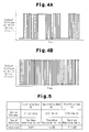
Fig. 4A is a graph showing fluctuation of the output voltage of the motor drive circuit in the two-phase modulation control; -
Fig. 4B is a graph showing fluctuation of the output voltage of the motor drive circuit in the three-phase modulation control; -
Fig. 5 is an explanatory chart showing a first drive mode, a second drive mode, and a third drive mode; and -
Fig. 6 is a graph showing changes in the temperature of the switching elements. - A motor-driven
compressor 10 according to one embodiment will now be described with reference toFigs. 1 to 6 . The motor-drivencompressor 10 of the present embodiment is mounted on a vehicle and employed for a vehicle air conditioner. - As shown in
Fig. 1 , the motor-drivencompressor 10 has ahousing 11, which accommodates acompression portion 12 and anelectric motor 13. Thecompression portion 12 compresses and discharges refrigerant, and theelectric motor 13 drives thecompression portion 12. Thecompression portion 12 includes afixed scroll 12a, which is fixed in thehousing 11, and anorbiting scroll 12b, which is arranged to be opposed to thefixed scroll 12a. Theelectric motor 13 includes arotor 13a and astator 13b. Therotor 13a is fixed to arotary shaft 15 to rotate integrally with therotary shaft 15, and thestator 13b is fixed to the inner circumferential surface of thehousing 11. - A
cover 16 is attached to the bottom wall of thehousing 11. Thecover 16 and the bottom wall of thehousing 11 define a space that accommodates a motor drive circuit 20 (indicated by a broken line inFig. 1 ) for driving theelectric motor 13. In the present embodiment, thecompression portion 12, theelectric motor 13, and themotor drive circuit 20 are arranged in the order along the axis L of therotary shaft 15. - As shown in
Fig. 2 , themotor drive circuit 20 has a plurality ofswitching elements switching elements diode 24. Thediodes 24 return electromotive force generated in theelectric motor 13 back to aDC power source 25. - The
switching elements control computer 30 so that signals can be transmitted therebetween. The collectors of theswitching elements DC power source 25, and the emitters of theswitching elements coil 13c of theelectric motor 13. The emitters of theswitching elements DC power source 25, and the collectors of theswitching elements coil 13c of theelectric motor 13. - The
motor drive circuit 20 controls the drive voltage of theelectric motor 13 through the pulse width modulation. Specifically, theswitching elements motor drive circuit 20 converts a DC voltage to an AC voltage. The obtained AC voltage is applied, as the drive voltage, to theelectric motor 13 to control the driving of theelectric motor 13. - The
control computer 30 generates a PWM signal with a high-frequency triangular wave signal, which is referred to as a carrier wave, and a voltage command signal for commanding a voltage value, and supplies the PWM signal to the bases of theswitching elements temperature sensor 31 is electrically connected to thecontrol computer 30. Thetemperature sensor 31 serves as a temperature detector that detects the temperature of theswitching elements temperature sensor 31 of the present embodiment is a thermistor that is located in the vicinity of theswitching elements temperature sensor 31, or the detection result, is delivered to thecontrol computer 30. - The
control computer 30 stores a control program for switching the drive mode of themotor drive circuit 20 to one of a first drive mode M1, a second drive mode M2, and a third drive mode M3, which are determined based on the carrier frequency and the modulation control. The "carrier frequency" refers to the frequency of the triangular wave signal. Therefore, thecontrol computer 30 functions as a switcher that switches the drive mode of themotor drive circuit 20 to one of the first drive mode M1, the second drive mode M2, and the third drive mode M3. That is, thecontrol computer 30 selects, as the drive mode of themotor drive circuit 20, one of the first drive mode M1, the second drive mode M2, and the third drive mode M3. -
Fig. 3A shows fluctuations of the current of theelectric motor 13 in the two-phase modulation control, andFig. 3B shows fluctuations of the current of theelectric motor 13 in the three-phase modulation control. The fluctuation of a waveform W1 shown inFig. 3A is greater than the fluctuation of a waveform W2 shown inFig. 3B . Thus, the two-phase modulation control has a greater fluctuation in the current of theelectric motor 13 compared to the three-phase modulation control, and a greater noise is generated during switching of the switchingelements -
Fig. 4A shows the fluctuation of the output voltage of themotor drive circuit 20 in the two-phase modulation control, andFig. 4B shows the fluctuation of the output voltage of themotor drive circuit 20 in the three-phase modulation control. In the three-phase modulation control, each of theswitching elements rotor 13a rotates 360°. Inthe two-phase modulation control, one of theswitching elements rotor 13a rotates 60°. That is, the switching element of one of the three phases is sequentially stopped, and, at the same time, the switching elements of the other two phases perform switching. Thus, in the two-phase modulation control, the switchingelements - As shown in
Fig. 5 , in the first drive mode M1, themotor drive circuit 20 is driven through the two-phase modulation control by using a preset first carrier frequency C1 (20 kHz in the present embodiment). In the present embodiment, the first carrier frequency C1 has a frequency outside the audible range. - In the second drive mode M2, the
motor drive circuit 20 is driven through the three-phase modulation control by using a second carrier frequency C2 (10 kHz in the present embodiment), which has a lower frequency than the first carrier frequency C1. In the present embodiment, the second carrier frequency C1 has a frequency within the audible range. - In the third drive mode M3, the
motor drive circuit 20 is driven through the two-phase modulation control by using a third carrier frequency C3 (10 kHz in the present embodiment), which has a lower frequency than the first carrier frequency C1. In the present embodiment, the third carrier frequency C3 has a frequency within the audible range. - The
control computer 30 stores a control program to switch the drive mode of themotor drive circuit 20 from the first drive mode M1 to the second drive mode M2 when acquiring information that indicates that the temperature detected by thetemperature sensor 31 has increased and reached a first preset temperature T1. The first preset temperature is preferably set in a range between 60°C and 80°C, inclusive. In the present embodiment, the first preset temperature is set to 70°C. - The
control computer 30 stores another control program to switch the drive mode of themotor drive circuit 20 from the second drive mode M2 to the third drive mode M3 when acquiring information that indicates that the temperature detected by thetemperature sensor 31 has increased and reached a second preset temperature T2, which is higher than the first preset temperature T1. The second preset temperature is preferably set in a range between 80°C and 100°C, inclusive. In the present embodiment, the second preset temperature is set to 90°C. The heat resistant temperature of the switchingelements - The
control computer 30 stores a control program, according to which, in a state in which themotor drive circuit 20 is being driven in the third drive mode M3, when receiving information indicating that the temperature detected by thetemperature sensor 31 has dropped to a third preset temperature T3, which is lower than the second present temperature T2, thecontrol computer 30 switches from the third drive mode M3 to the second drive mode M2. The third preset temperature T3 is set to be higher than the first preset temperature T1. In the present embodiment, the third preset temperature T3 is set to 85°C. - Further, the
control computer 30 stores a control program, according to which, in a state in which themotor drive circuit 20 is being driven in the second drive mode M2, when receiving information indicating that the temperature detected by thetemperature sensor 31 has dropped to a fourth preset temperature T4, which is lower than the first present temperature T1, thecontrol computer 30 switches from the second drive mode M2 to the first drive mode M1. In the present embodiment, the fourth preset temperature T4 is set to 65°C. - In the present embodiment, the first preset temperature T1, the second preset temperature T2, the third preset temperature T3, and the fourth preset temperature T4 are set to not exceed the heat resistance temperature of the switching
elements motor drive circuit 20 is driven in the first drive mode M1 is wider than the temperature ranges in which themotor drive circuit 20 is driven in the second drive mode M2 and the third drive mode M3, respectively. Also, the first preset temperature T1, the second preset temperature T2, the third preset temperature T3, and the fourth preset temperature T4 are set to not exceed the heat resistance temperature of the switchingelements motor drive circuit 20 is driven in the third drive mode M3 is narrower than the temperature range in which themotor drive circuit 20 is driven in the second drive mode M2. - Operation of the present embodiment will now be described.
- As shown in
Fig. 6 , themotor drive circuit 20 is driven in the first drive mode M1 until the temperature detected by thetemperature sensor 31 is raised to reach the first preset temperature T1. In the first drive mode M1, themotor drive circuit 20 is driven at the first carrier frequency C1, which is higher than the second carrier frequency C2 and the third carrier frequency C3. Thus, the noise due to switching of the switchingelements motor drive circuit 20 is driven in the second drive mode M2 or the third drive mode M3. In the present embodiment, the noise due to switching of the switchingelements - In the first drive mode M1, the two-phase modulation control is executed. In the first drive mode M1, the
motor drive circuit 20 is driven at the first carrier frequency C1, which is higher than the second carrier frequency C2 and the third carrier frequency C3. Thus, even if the two-phase modulation control is executed, the noise due to switching of theswitching elements motor drive circuit 20 is driven in the first drive mode M1, heat generation in theswitching elements - Thereafter, when the temperature detected by the
temperature sensor 31 is raised and reaches the first preset temperature T1, thecontrol computer 30 switches the drive mode of themotor drive circuit 20 from the first drive mode M1 to the second drive mode M2. - In the second drive mode M2, the
motor drive circuit 20 is driven by using the second carrier frequency C2, which is lower than the first carrier frequency C1. Thus, switching of the switchingelements motor drive circuit 20 is driven in the first drive mode M1, so that heat generation in theswitching elements - Further, since the three-phase modulation control is performed in the second drive mode M2, the current of the
electric motor 13 fluctuate to a smaller extent than in the two-phase modulation control, so that the noise generated due to switching of theswitching elements elements - When the temperature detected by the
temperature sensor 31 is raised and reaches the second preset temperature T2, thecontrol computer 30 switches the drive mode of themotor drive circuit 20 from the second drive mode M2 to the third drive mode M3. - In the third drive mode M3, the
motor drive circuit 20 is driven by using the third carrier frequency C3, which is lower than the first carrier frequency C1. Thus, switching of the switchingelements motor drive circuit 20 is driven in the first drive mode M1, so that heat generation in theswitching elements - In the third drive mode M3, the two-phase modulation control is executed. Thus, in the third drive mode M3, the switching
elements switching elements motor drive circuit 20 is driven in the second drive mode M2. In the present embodiment, the noise due to switching of the switchingelements - The second preset temperature T2 is set to be higher than the first preset temperature T1. Therefore, in the third drive mode M3, for example, the
motor drive circuit 20 can be driven until the temperature of the switchingelements motor drive circuit 20 thus can be driven in a wide temperature range. In other words, the motor-drivencompressor 10 can be operated in a wide temperature range. - As described above, the drive mode of the
motor drive circuit 20 is switched to one of the first drive mode M1, the second drive mode M2, and the third drive mode M3 based on the temperature detected by thetemperature sensor 31. This suppresses heat generation in theswitching elements elements elements - In a state in which the
motor drive circuit 20 is driven in the third drive mode M3, when receiving information indicating that the temperature detected by thetemperature sensor 31 has dropped to the third preset temperature T3, which is lower than the second present temperature T2, thecontrol computer 30 switches the drive mode of themotor drive circuit 20 from the third drive mode M3 to the second drive mode M2. Therefore, themotor drive circuit 20 is prevented from being driven in the third drive mode M3 when the temperature detected by thetemperature sensor 31 is still sufficiently separate from the second preset temperature T2. Thus, themotor drive circuit 20 is driven in the second drive mode M2, in which the noise due to switching of the switchingelements - In a state in which the
motor drive circuit 20 is driven in the second drive mode M2, when receiving information indicating that the temperature detected by thetemperature sensor 31 has dropped to the fourth preset temperature T4, which is lower than the first present temperature T1, thecontrol computer 30 switches the drive mode of themotor drive circuit 20 from the second drive mode M2 to the first drive mode M1. Therefore, themotor drive circuit 20 is prevented from being driven in the second drive mode M2 when the temperature detected by thetemperature sensor 31 is still sufficiently separate from the first preset temperature T1. Thus, themotor drive circuit 20 is driven in the first drive mode M1, in which the noise due to switching of the switchingelements - The above described embodiment provides the following advantages.
- (1) The
control computer 30 switches the drive mode of themotor drive circuit 20 from the first drive mode M1 to the second drive mode M2 when acquiring information that indicates that the temperature detected by thetemperature sensor 31 has increased and reached the first preset temperature T1. Also, thecontrol computer 30 switches the drive mode of themotor drive circuit 20 from the second drive mode M2 to the third drive mode M3 when acquiring information that indicates that the temperature detected by thetemperature sensor 31 has increased and reached the second preset temperature T2, which is higher than the first preset temperature T1.
Accordingly, themotor drive circuit 20 is driven in one of the first drive mode M1, the second drive mode M2, and the third drive mode M3, which are different in the frequency of the switching of the switchingelements elements motor drive circuit 20 is switched to one of the first drive mode M1, the second drive mode M2, and the third drive mode M3 based on the temperature detected by thetemperature sensor 31. This suppresses heat generation in theswitching elements elements - (2) In the first drive mode M1, the
motor drive circuit 20 is driven at the first carrier frequency C1, which is higher than the second carrier frequency C2 and the third carrier frequency C3. Thus, the noise due to switching of the switchingelements motor drive circuit 20 is driven in the second drive mode M2 or the third drive mode M3. Further, in the first drive mode M1, themotor drive circuit 20 is driven at the first carrier frequency C1, which is higher than the second carrier frequency C2 and the third carrier frequency C3. Thus, even if the two-phase conversion control is executed, the noise due to switching of theswitching elements motor drive circuit 20 is driven in the first drive mode M1, heat generation in theswitching elements - (3) In the second drive mode M2, the
motor drive circuit 20 is driven by using the second carrier frequency C2, which is lower than the first carrier frequency C1. Thus, switching of the switchingelements motor drive circuit 20 is driven in the first drive mode M1, so that heat generation in theswitching elements electric motor 13 fluctuate to a smaller extent than in the two-phase modulation control, so that the noise generated due to switching of the switchingelements - (4) In the third drive mode M3, the
motor drive circuit 20 is driven by using the third carrier frequency C3, which is lower than the first carrier frequency C1. Thus, switching of the switchingelements motor drive circuit 20 is driven in the first drive mode M1, so that heat generation in theswitching elements elements switching elements motor drive circuit 20 is driven in the second drive mode M2. - (5) The
control computer 30 switches the drive mode of themotor drive circuit 20 from the third drive mode M3 to the second drive mode M2 when acquiring information that indicates that the temperature detected by thetemperature sensor 31 has dropped to the third preset temperature T3, which is lower than the second preset temperature T2. Also, thecontrol computer 30 switches the drive mode of themotor drive circuit 20 from the second drive mode M2 to the first drive mode M1 when acquiring information that indicates that the temperature detected by thetemperature sensor 31 has dropped to the fourth preset temperature T4, which is lower than the first preset temperature T1.
Accordingly, even after the drive mode of themotor drive circuit 20 is switched to the third drive mode M3 by thecontrol computer 30 based on an increase in the temperature detected by thetemperature sensor 31, the drive mode of themotor drive circuit 20 can be switched from the third drive mode M3 to the second drive mode M2. Also, even after the drive mode of themotor drive circuit 20 is switched to the second drive mode M2 by thecontrol computer 30 based on an increase in the temperature detected by thetemperature sensor 31, the drive mode of themotor drive circuit 20 can be switched from the second drive mode M2 to the first drive mode M1. In this manner, themotor drive circuit 20 can be driven with its drive mode switched to the optimum one in accordance with the temperature condition. - (6) The first preset temperature T1, the second preset temperature T2, the third preset temperature T3, and the fourth preset temperature T4 are set to not exceed the heat resistance temperature of the switching
elements motor drive circuit 20 is driven in the first drive mode M1 is wider than the temperature ranges in which themotor drive circuit 20 is driven in the second drive mode M2 and the third drive mode M3, respectively. This expands the temperature range in which themotor drive circuit 20 is driven in the first drive mode M1, in which the noise due to switching of the switchingelements elements - (7) The first preset temperature T1, the second preset temperature T2, the third preset temperature T3, and the fourth preset temperature T4 are set to not exceed the heat resistance temperature of the switching
elements motor drive circuit 20 is driven in the third drive mode M3 is narrower than the temperature range in which themotor drive circuit 20 is driven in the second drive mode M2. This narrows the temperature range in which themotor drive circuit 20 is driven in the third drive mode M3, in which the noise due to switching of the switchingelements elements - (8) The
control computer 30 switches the drive mode of themotor drive circuit 20 from the second drive mode M2 to the first drive mode M1 when the temperature detected by thetemperature sensor 31 has dropped to the fourth preset temperature T4, which is lower than the first preset temperature T1. Therefore, for example, themotor drive circuit 20 is prevented from being driven in the second drive mode M2 when the temperature detected by thetemperature sensor 31 is still sufficiently separate from the first preset temperature T1. - (9) The second preset temperature T2 is set to be higher than the first preset temperature T1. Therefore, in the third drive mode M3, for example, the
motor drive circuit 20 can be driven until the temperature of the switchingelements motor drive circuit 20 thus can be driven in a wide temperature range. - The above described embodiment may be modified as follows.
- In the above illustrated embodiment, the
control computer 30 may control themotor drive circuit 20 to start being driven in the second drive mode M2. That is, when activating the motor-drivencompressor 10, themotor drive circuit 20 is driven in the second drive mode M2 if the temperature detected by thetemperature sensor 31 is higher than the first preset temperature T1. - In the illustrated embodiment, the
control computer 30 may switch the drive mode of themotor drive circuit 20 from the first drive mode M1 to the third drive mode M3 based on the temperature detected by thetemperature sensor 31. - In the illustrated embodiment, the
control computer 30 may switch the drive mode of themotor drive circuit 20 from the third drive mode M3 to the first drive mode M1 based on the temperature detected by thetemperature sensor 31. - In the illustrated embodiment, the
control computer 30 may switch the drive mode of themotor drive circuit 20 from the second drive mode M2 to the first drive mode M1 when the temperature detected by thetemperature sensor 31 drops to a predetermined temperature after a predetermined time period has elapsed from when the drive mode was switched, for example, from the first drive mode M1 to the second drive mode M2. Likewise, thecontrol computer 30 may switch the drive mode of themotor drive circuit 20 from the third drive mode M3 to the second drive mode M2 when the temperature detected by thetemperature sensor 31 drops to a predetermined temperature after a predetermined time period has elapsed from when the drive mode was switched, for example, from the second drive mode M2 to the third drive mode M3. - In the illustrated embodiment, the
control computer 30 may switch the drive mode of themotor drive circuit 20 by selecting one of the first drive mode M1, the second drive mode M2, and the third drive mode M3 based on a value calculated based on the temperature detected by thetemperature sensor 31. - In the illustrated embodiment, the
control computer 30 may switch the drive mode of themotor drive circuit 20 by selecting one of the first drive mode M1, the second drive mode M2, and the third drive mode M3 based on a map that uses the temperature detected by thetemperature sensor 31. - In the illustrated embodiment, the three-phase conversion control may be executed in the first drive mode M1.
- In the illustrated embodiment, the first carrier frequency C1 may be higher than 20 kHz.
- In the illustrated embodiment, the third carrier frequency C3 may be lower than the second carrier frequency C2.
- In the illustrated embodiment, a thermocouple or a radiation thermometer may be used as the
temperature sensor 31. - In the illustrated embodiment, the
cover 16 may be fixed to the peripheral wall of thehousing 11, and themotor drive circuit 20 may be accommodated in the space defined by the peripheral wall of thehousing 11 and thecover 16. - In the illustrated embodiment, the
compression portion 12 may be a piston type or a vane type. - In the illustrated embodiment, the motor-driven
compressor 10 may be used in any type of air conditioner instead of a vehicle air conditioner. - Therefore, the present examples and embodiments are to be considered as illustrative and not restrictive and the invention is not to be limited to the details given herein, but may be modified within the scope and equivalence of the appended claims.
- A motor-driven compressor includes a compression portion, an electric motor, a motor drive circuit having switching element, a temperature detector, and a switcher, which switches the drive mode of the motor drive circuit. When acquiring information indicating that the temperature detected by the temperature detector has increased and reached a first preset temperature, the switcher switches the drive mode of the motor drive circuit from a first drive mode to a second drive mode. Also, when acquiring information indicating that the temperature detected by the temperature detector has increased and reached a second preset temperature, which is higher than the first preset temperature, the switcher switches the drive mode of the motor drive circuit from the first drive mode or the second drive mode to a third drive mode.
Claims (7)
- A motor-driven compressor comprising:a compression portion (12);an electric motor (13), which drives the compression portion (12);a motor drive circuit (20), which drives the electric motor (13), wherein the motor drive circuit (20) has a switching element (21 a-21 c, 22a-22c) for converting a DC voltage into an AC voltage;a temperature detector (31), which detects a temperature of the switching element (21 a-21 c, 22a-22c); anda switcher (30), which switches a drive mode of the motor drive circuit (20) to one of a first drive mode (M1), a second drive mode (M2), and a third drive mode (M3), which are determined by a carrier frequency and modulation control, whereinwhen acquiring information indicating that the temperature detected by the temperature detector (31) has increased and reached a first preset temperature (T1), the switcher (30) switches the drive mode of the motor drive circuit (20) from the first drive mode (M1) to the second drive mode (M2), andwhen acquiring information indicating that the temperature detected by the temperature detector (31) has increased and reached a second preset temperature (T2), which is higher than the first preset temperature (T1), the switcher (30) switches the drive mode of the motor drive circuit (20) from the first drive mode (M1) or the second drive mode (M2) to the third drive mode (M3).
- The motor-driven compressor according to claim 1, wherein
in the first drive mode (M1), two-phase modulation control is executed by using a predetermined first carrier frequency (C1),
in the second drive mode (M2), three-phase modulation control is executed by using a second carrier frequency (C2), which is lower than the first carrier frequency (C1), and
in the third drive mode (M3), two-phase modulation control is executed by using a third carrier frequency (C3), which is lower than the first carrier frequency (C1). - The motor-driven compressor according to claim 2, wherein
the first carrier frequency (C1) is outside the audible range,
the second carrier frequency (C2) is within the audible range, and
the third carrier frequency (C3) is within the audible range. - The motor-driven compressor according to claim 2, wherein
when acquiring information indicating that the temperature detected by the temperature detector (31) has dropped to a third preset temperature (T3), which is lower than the second preset temperature (T2), the switcher (30) switches the drive mode of the motor drive circuit (20) from the third drive mode (M3) to the second drive mode (M2), and
when acquiring information indicating that the temperature detected by the temperature detector (31) has dropped to a fourth preset temperature (T4), which is lower than the first preset temperature (T1), the switcher (30) switches the drive mode of the motor drive circuit (20) from the second drive mode (M2) or the third drive mode (M3) to the first drive mode (M1). - The motor-driven compressor according to claim 4, wherein the first preset temperature (T1), the second preset temperature (T2), the third preset temperature (T3), and the fourth preset temperature (T4) are set to not exceed a heat resistance temperature of the switching element (21a-21c, 22a-22c) such that a temperature range in which the motor drive circuit (20) is driven in the first drive mode (M1) is wider than a temperature range in which the motor drive circuit (20) is driven in the second drive mode (M2) and a temperature range in which the motor drive circuit (20) is driven in the third drive mode (M3).
- The motor-driven compressor according to claim 5, wherein the first preset temperature (T1), the second preset temperature (T2), the third preset temperature (T3), and the fourth preset temperature (T4) are set to not exceed the heat resistance temperature of the switching element (21a-21c, 22a-22c) such that a temperature range in which the motor drive circuit (20) is driven in the third drive mode (M3) is narrower than the temperature range in which the motor drive circuit (20) is driven in the second drive mode (M2).
- The motor-driven compressor according to any one of claims 1 to 6, wherein
the first preset temperature (T1) is set in a range between 60°C and 80°C, inclusive, and
the second preset temperature (T2) is set in a range between 80°C and 100°C, inclusive.
Applications Claiming Priority (1)
| Application Number | Priority Date | Filing Date | Title |
|---|---|---|---|
| JP2013201771A JP6123615B2 (en) | 2013-09-27 | 2013-09-27 | Electric compressor |
Publications (1)
| Publication Number | Publication Date |
|---|---|
| EP2854285A1 true EP2854285A1 (en) | 2015-04-01 |
Family
ID=51584970
Family Applications (1)
| Application Number | Title | Priority Date | Filing Date |
|---|---|---|---|
| EP14185291.3A Withdrawn EP2854285A1 (en) | 2013-09-27 | 2014-09-18 | Motor-driven compressor |
Country Status (5)
| Country | Link |
|---|---|
| US (1) | US20150093254A1 (en) |
| EP (1) | EP2854285A1 (en) |
| JP (1) | JP6123615B2 (en) |
| KR (1) | KR101697538B1 (en) |
| CN (1) | CN104518730A (en) |
Families Citing this family (7)
| Publication number | Priority date | Publication date | Assignee | Title |
|---|---|---|---|---|
| JP6217667B2 (en) * | 2015-02-19 | 2017-10-25 | 株式会社豊田自動織機 | Electric compressor |
| CN107810596B (en) * | 2015-07-10 | 2020-07-28 | 株式会社日立产机系统 | Power conversion device and temperature reduction method thereof |
| CN107367095B (en) * | 2017-07-28 | 2020-08-04 | 广东美芝制冷设备有限公司 | Compressor power module temperature control method and control system |
| JP6963495B2 (en) * | 2017-12-22 | 2021-11-10 | サンデンホールディングス株式会社 | Power converter |
| JP6847273B2 (en) * | 2018-01-25 | 2021-03-24 | 三菱電機株式会社 | Motor drive and air conditioner |
| CN114679102A (en) * | 2020-12-24 | 2022-06-28 | 南京泉峰科技有限公司 | Electric tool and its control method |
| CN115157182A (en) | 2021-04-07 | 2022-10-11 | 南京泉峰科技有限公司 | Electric tool |
Citations (4)
| Publication number | Priority date | Publication date | Assignee | Title |
|---|---|---|---|---|
| JP2005201108A (en) | 2004-01-14 | 2005-07-28 | Sanden Corp | Electric compressor |
| US20050194925A1 (en) * | 2004-02-10 | 2005-09-08 | Denso Corporation | Apparatus for controlling three-phase AC motor on two-phase modulation technique |
| WO2006006288A1 (en) * | 2004-07-09 | 2006-01-19 | Matsushita Electric Industrial Co., Ltd. | Inverter circuit and compressor |
| US20090115362A1 (en) * | 2007-11-01 | 2009-05-07 | Aisin Aw Co., Ltd. | Electric motor control device, electric vehicle, and hybrid electric vehicle |
Family Cites Families (8)
| Publication number | Priority date | Publication date | Assignee | Title |
|---|---|---|---|---|
| JP4032739B2 (en) * | 2001-12-27 | 2008-01-16 | アイシン・エィ・ダブリュ株式会社 | Motor control device |
| JP2004289985A (en) * | 2003-03-25 | 2004-10-14 | Matsushita Electric Ind Co Ltd | Inverter control device for motor drive and air conditioner |
| JP5197924B2 (en) * | 2006-04-13 | 2013-05-15 | シャープ株式会社 | Motor controller, refrigerator, air conditioner |
| JP2010221856A (en) * | 2009-03-24 | 2010-10-07 | Hitachi Automotive Systems Ltd | Steering control device |
| JP2011109803A (en) * | 2009-11-17 | 2011-06-02 | Toyota Motor Corp | Device for controlling electric motor |
| KR101571905B1 (en) * | 2010-10-04 | 2015-11-26 | 현대자동차주식회사 | Sub air conditioner for vehicles |
| JP5873716B2 (en) * | 2011-12-28 | 2016-03-01 | 日立アプライアンス株式会社 | Motor control device |
| JP6217667B2 (en) * | 2015-02-19 | 2017-10-25 | 株式会社豊田自動織機 | Electric compressor |
-
2013
- 2013-09-27 JP JP2013201771A patent/JP6123615B2/en active Active
-
2014
- 2014-09-18 EP EP14185291.3A patent/EP2854285A1/en not_active Withdrawn
- 2014-09-23 KR KR1020140127044A patent/KR101697538B1/en not_active Expired - Fee Related
- 2014-09-24 CN CN201410495293.5A patent/CN104518730A/en active Pending
- 2014-09-26 US US14/497,804 patent/US20150093254A1/en not_active Abandoned
Patent Citations (4)
| Publication number | Priority date | Publication date | Assignee | Title |
|---|---|---|---|---|
| JP2005201108A (en) | 2004-01-14 | 2005-07-28 | Sanden Corp | Electric compressor |
| US20050194925A1 (en) * | 2004-02-10 | 2005-09-08 | Denso Corporation | Apparatus for controlling three-phase AC motor on two-phase modulation technique |
| WO2006006288A1 (en) * | 2004-07-09 | 2006-01-19 | Matsushita Electric Industrial Co., Ltd. | Inverter circuit and compressor |
| US20090115362A1 (en) * | 2007-11-01 | 2009-05-07 | Aisin Aw Co., Ltd. | Electric motor control device, electric vehicle, and hybrid electric vehicle |
Also Published As
| Publication number | Publication date |
|---|---|
| KR20150035415A (en) | 2015-04-06 |
| KR101697538B1 (en) | 2017-01-18 |
| JP2015070672A (en) | 2015-04-13 |
| CN104518730A (en) | 2015-04-15 |
| JP6123615B2 (en) | 2017-05-10 |
| US20150093254A1 (en) | 2015-04-02 |
Similar Documents
| Publication | Publication Date | Title |
|---|---|---|
| US20150093254A1 (en) | Motor-driven compressor | |
| US9964111B2 (en) | Motor-driven compressor with switching element | |
| CN101291127B (en) | Inverter circuit and compressor | |
| JP6217667B2 (en) | Electric compressor | |
| JP6127275B2 (en) | Motor drive device and refrigerator using the same | |
| JP5378630B1 (en) | Electric compressor control method, control device, and refrigerator | |
| JP6217668B2 (en) | Electric compressor | |
| US9938976B2 (en) | Motor-driven compressor with switching element | |
| US20180145616A1 (en) | Dc-brushless-motor control device | |
| CN102454587B (en) | Motor-driven compressor and controller therefor | |
| JP6970871B2 (en) | Motor drive device and refrigerator using it | |
| US9790944B2 (en) | Motor-driven compressor with switching element | |
| JP2009189202A (en) | Power converter, brushless DC motor and ventilation blower | |
| JP4927521B2 (en) | Vacuum cleaner | |
| KR20080090714A (en) | Compressor Drive and Method | |
| JP6074235B2 (en) | Motor control device | |
| JP2006223014A (en) | Motor drive device | |
| JP2022086671A (en) | Motor compressor | |
| JP2004324552A (en) | Electric compressor | |
| JP2016089748A (en) | Motor-driven compressor | |
| JP2006025542A (en) | refrigerator | |
| JP2010246333A (en) | Motor drive device and refrigerator using the same | |
| JP2018121373A (en) | Heat source equipment |
Legal Events
| Date | Code | Title | Description |
|---|---|---|---|
| PUAI | Public reference made under article 153(3) epc to a published international application that has entered the european phase |
Free format text: ORIGINAL CODE: 0009012 |
|
| 17P | Request for examination filed |
Effective date: 20140918 |
|
| AK | Designated contracting states |
Kind code of ref document: A1 Designated state(s): AL AT BE BG CH CY CZ DE DK EE ES FI FR GB GR HR HU IE IS IT LI LT LU LV MC MK MT NL NO PL PT RO RS SE SI SK SM TR |
|
| AX | Request for extension of the european patent |
Extension state: BA ME |
|
| STAA | Information on the status of an ep patent application or granted ep patent |
Free format text: STATUS: THE APPLICATION HAS BEEN WITHDRAWN |
|
| 18W | Application withdrawn |
Effective date: 20181228 |