EP2854258A1 - Permanent magnet rotor shaft assembly and method - Google Patents
Permanent magnet rotor shaft assembly and method Download PDFInfo
- Publication number
- EP2854258A1 EP2854258A1 EP20130306322 EP13306322A EP2854258A1 EP 2854258 A1 EP2854258 A1 EP 2854258A1 EP 20130306322 EP20130306322 EP 20130306322 EP 13306322 A EP13306322 A EP 13306322A EP 2854258 A1 EP2854258 A1 EP 2854258A1
- Authority
- EP
- European Patent Office
- Prior art keywords
- cylindrical core
- permanent magnet
- central
- end shafts
- rotor shaft
- Prior art date
- Legal status (The legal status is an assumption and is not a legal conclusion. Google has not performed a legal analysis and makes no representation as to the accuracy of the status listed.)
- Granted
Links
Images
Classifications
-
- H—ELECTRICITY
- H02—GENERATION; CONVERSION OR DISTRIBUTION OF ELECTRIC POWER
- H02K—DYNAMO-ELECTRIC MACHINES
- H02K1/00—Details of the magnetic circuit
- H02K1/06—Details of the magnetic circuit characterised by the shape, form or construction
- H02K1/22—Rotating parts of the magnetic circuit
- H02K1/28—Means for mounting or fastening rotating magnetic parts on to, or to, the rotor structures
-
- H—ELECTRICITY
- H02—GENERATION; CONVERSION OR DISTRIBUTION OF ELECTRIC POWER
- H02K—DYNAMO-ELECTRIC MACHINES
- H02K1/00—Details of the magnetic circuit
- H02K1/06—Details of the magnetic circuit characterised by the shape, form or construction
- H02K1/22—Rotating parts of the magnetic circuit
- H02K1/27—Rotor cores with permanent magnets
- H02K1/2706—Inner rotors
- H02K1/272—Inner rotors the magnetisation axis of the magnets being perpendicular to the rotor axis
- H02K1/2726—Inner rotors the magnetisation axis of the magnets being perpendicular to the rotor axis the rotor consisting of a single magnet or two or more axially juxtaposed single magnets
-
- F—MECHANICAL ENGINEERING; LIGHTING; HEATING; WEAPONS; BLASTING
- F16—ENGINEERING ELEMENTS AND UNITS; GENERAL MEASURES FOR PRODUCING AND MAINTAINING EFFECTIVE FUNCTIONING OF MACHINES OR INSTALLATIONS; THERMAL INSULATION IN GENERAL
- F16C—SHAFTS; FLEXIBLE SHAFTS; ELEMENTS OR CRANKSHAFT MECHANISMS; ROTARY BODIES OTHER THAN GEARING ELEMENTS; BEARINGS
- F16C32/00—Bearings not otherwise provided for
- F16C32/04—Bearings not otherwise provided for using magnetic or electric supporting means
- F16C32/0406—Magnetic bearings
- F16C32/044—Active magnetic bearings
- F16C32/0459—Details of the magnetic circuit
- F16C32/0468—Details of the magnetic circuit of moving parts of the magnetic circuit, e.g. of the rotor
-
- Y—GENERAL TAGGING OF NEW TECHNOLOGICAL DEVELOPMENTS; GENERAL TAGGING OF CROSS-SECTIONAL TECHNOLOGIES SPANNING OVER SEVERAL SECTIONS OF THE IPC; TECHNICAL SUBJECTS COVERED BY FORMER USPC CROSS-REFERENCE ART COLLECTIONS [XRACs] AND DIGESTS
- Y10—TECHNICAL SUBJECTS COVERED BY FORMER USPC
- Y10T—TECHNICAL SUBJECTS COVERED BY FORMER US CLASSIFICATION
- Y10T29/00—Metal working
- Y10T29/49—Method of mechanical manufacture
- Y10T29/49002—Electrical device making
- Y10T29/49009—Dynamoelectric machine
- Y10T29/49012—Rotor
Definitions
- the present invention relates to a permanent magnet rotor shaft assembly for high speed electrical machines and a method of manufacture thereof.
- Document US 4741094 A and document WO 98/34324 A1 disclose a method of making a two-pole magnet rotor for an electrical machine, comprising the steps of forming a cylindrical two-pole permanent magnet from either small blocks aligned with the same axis of magnetic polarity assembled in a solid overlaying relationship or a whole cylindrical block ( WO 98/34324 A1 ); bonding a first end piece onto one end of the cylindrical two-pole permanent magnet; bonding a second end piece onto the other end of the cylindrical two-pole permanent magnet; and installing a thin cylindrical retaining hoop in interference fit fashion around the cylindrical two-pole permanent magnet and the portions of the first and second end pieces adjacent to the cylindrical two-pole permanent magnet.
- This method of manufacturing an assembly with two end shafts, a magnet cylinder made of a plurality of magnets assembled as a core, this core being axially compressed by end shafts and the set being radially compressed and fixed by a high tensile sleeve, is rather cost effective and is in line for serial production.
- a method remains difficult to put into practice in particular because it is difficult to insure a concentric alignment while inserting the sleeve.
- Document US 7042118 B2 further discloses a rotor construction method aiming at improving the concentric alignment when inserting a sleeve. According to such a method a plurality of hollow magnet discs are provided and a tie rod is placed in the central bores of the hollow magnet discs and fixed to end shafts. Such a method is not cost effective and the use of hollow magnet discs might be detrimental to the stiffness and efficiency of the assembly.
- the technical problem to be solved is to provide a permanent magnet rotor shaft assembly for high speed electrical machines and a method of manufacture thereof which remedy the above-mentioned drawbacks.
- the invention aims at improving the easiness of a manufacturing process with a reduced number of pieces arranged on a shaft.
- the invention further aims at allowing the possibility of creating a rotor assembly providing a high stiffness permanent rotor shaft.
- Another aim of the present invention is to have a simplified manufacturing process, enabling a lower cost and a high serial manufacturing process.
- the invention more specifically relates to a permanent rotor shaft assembly for an electrical machine, comprising a permanent magnet cylindrical core having a longitudinal axis, said cylindrical core being axially compressed by first and second end shafts and being radially compressed by a sleeve made of a non-magnetic high strength metal, characterized in that at least one of said first and second end shafts comprises, in its portion facing said cylindrical core, a central shoulder head which cooperates with a mating central recess made in a central portion of a front face of said cylindrical core.
- the permanent magnet cylindrical core may comprise rare earth magnets which may be made of NdFeBr or Sm2Co17 for example.
- the sleeve may be made of a non-magnetic high strength metal such as Inconel, Hastelloy, Ti-6%Al-6%V-2%Sn, Ti-2.5%Cu.
- the central shoulder head may be inserted in the mating central recess by tight fit assembly, slip joint assembly or glued assembly.
- the first and second end shafts and the sleeve may be fixed on the permanent magnet cylindrical core by welding, adhesive or heat shrinking.
- first and second end shafts further comprise cylindrical tracks for mechanical bearings.
- Such cylindrical tracks for mechanical bearings may be located on a stepped portion of the first and second end shafts.
- first and second end shafts may further comprise cylindrical stack iron laminations for magnetic bearings.
- Such cylindrical stack iron laminations for magnetic bearings may be located on a stepped portion of the first and second end shafts.
- a central shoulder head is provided in each of the first and second end shafts, in its portion facing the cylindrical core, a mating central recess is provided in each of the central portions of the front faces of the cylindrical core, and the central shoulder heads are respectively mounted in the mating central recesses.
- the permanent magnet cylindrical core may form a two-pole permanent magnet or a four-pole permanent magnet.
- the invention further relates to a rotary high speed electrical machine having tip speeds up to 300 m/s, characterized in that it comprises a permanent rotor shaft assembly as defined above.
- the invention further relates to a method for making a permanent rotor shaft assembly for an electrical machine, comprising the steps of:
- a central shoulder head is provided in each of said first and second end shafts, in its portion facing said cylindrical core, a mating central recess is provided in each of the central portions of the front faces of said cylindrical core, and said central shoulder heads are respectively mounted in said mating central recesses, before inserting said sleeve made of a non-magnetic high strength metal in interference fit fashion around said permanent magnet cylindrical core and the portions of said first and second end shafts adjacent to said permanent magnet cylindrical core.
- the central shoulder head may be inserted in a mating central recess by tight fit assembly, slip joint assembly or glued assembly.
- the first and second end shafts and the sleeve may be fixed to the permanent magnet cylindrical core by welding, adhesive or heat shrinking.
- the invention more specifically allows an easy concentric alignment of the first and second end shafts with the permanent magnet cylindrical core while inserting the sleeve. Moreover it increases the stiffness on the set once assembled.
- FIG. 1 shows a permanent rotor shaft assembly 100 for an electrical machine, more specifically for high speed applications which can reach tip speeds up to 300 m/s.
- the assembly 100 comprises a permanent magnet cylindrical core 101 having a longitudinal axis X-X'.
- the cylindrical core 101 is axially compressed by first and second end shafts 102A, 102B and is radially compressed by a sleeve 104 made of a non-magnetic high strength metal.
- the set of elements 101, 102A and 102B forms the overall rotor shaft.
- one (102A) of the first and second end shafts 102A, 102B comprises, in its portion facing the cylindrical core 101, a central shoulder head 103A which cooperates with a mating central recess 106A made in a central portion of a front face of the cylindrical core 101.
- the shoulder head 103A insures the concentricity of the elements 101 and 102A during the assembly process and provides support for the cylindrical magnet core 101, whilst introducing additional stiffness to the set of assembled elements 101, 102A and 102B once the mounting process is achieved.
- the permanent magnet cylindrical core 101 comprises rare earth magnets such as NdFeBr or Sm2Co17.
- the sleeve 104 is made of a non-magnetic high strength metal which may be advantageously chosen among Inconel, Hastelloy, Ti-6%Al-6%V-2%Sn, Ti-2.5%Cu.
- the magnetization direction of the magnet 101 may be radial, diametral or constituted by a Halbach magnetization.
- the polarity of the magnets of the core 101 can be 2 poles or 4 poles.
- the central shoulder head 103A is inserted in the mating central recess by tight fit assembly, slip joint assembly or glued assembly.
- the first and second end shafts 102A, 102B and the sleeve 104 are fixed on the permanent magnet cylindrical core 101 by welding, adhesive or heat shrinking.
- the sleeve 104 constitutes a hoop which radially compresses the permanent magnet cylindrical core 101 and the first and second end shafts 102A, 102B.
- the first and second end shafts 102A, 102B axially compress the permanent magnet cylindrical core 101.
- first and second end shafts 102A, 102B further comprise cylindrical tracks 105A, 105B for mechanical bearings.
- the reference numerals 105A, 105B may also alternatively represent cylindrical stack iron laminations for magnetic bearings. Such cylindrical stack iron laminations may be made on the first and second end shafts 102A, 102B as an alternative for cylindrical tracks for mechanical bearings, but the first and second end shafts 102A, 102B may also comprise simultaneously in a not shown embodiment a combination of both cylindrical tracks for mechanical bearings (such as auxiliary bearings associated with magnetic bearings) and cylindrical stack iron laminations for magnetic bearings.
- the tracks for mechanical bearings and/or the stack iron laminations for magnetic bearings may be located on a stepped portion 122A, 122B of the first and second end shafts 102A, 102B.
- the elements 105A, 105B may be located at different levels (different area or different shoulder) of the end shafts according to the needs.
- Figs 2 and 3 illustrate a second embodiment of the invention which relates to a permanent rotor shaft assembly 200 for an electrical machine, more specifically for high speed applications which can reach tip speeds up to 300 m/s.
- the permanent rotor shaft assembly 200 comprises a permanent magnet cylindrical core 201 having a longitudinal axis X-X'.
- the cylindrical core 201 is axially compressed by first and second end shafts 202A, 202B and is radially compressed by a sleeve 204 made of a non-magnetic high strength metal.
- the set of elements 201, 202A and 202B forms the overall rotor shaft in a manner similar to the overall rotor shaft of the assembly 100 of the first embodiment.
- a central shoulder head 203A, 203B is provided in each of the first and second end shafts 202A, 202B, in its portion facing the cylindrical core 201, a mating central recess 206A, 206B is provided in each of the central portions of the front faces of the cylindrical core 201, and the central shoulder heads 203A, 203B are respectively mounted in the mating central recesses 206A, 206B.
- Such arrangement of the second embodiment is otherwise similar to the first embodiment and the same materials, assembly means and optional features such as the additional tracks or stack iron laminations 105A, 105B of Fig. 1 may also be applied to the embodiment of Fig. 2 .
- the assembly 200 of Fig. 2 nevertheless constitutes a best mode of implementation of the invention and ensures an easy concentric alignment of the elements 202A, 201, 202B, whilst inserting the sleeve 204 and confers an enhanced stiffness on the set of elements once assembled.
- the invention further relates to a method for making a permanent rotor shaft assembly 100 or 200 for an electrical machine, comprising the steps of:
- the method according to the invention further comprises the steps of:
- a central shoulder head 203A, 203B is provided in each of the first and second end shafts 202A, 202B, in its portion facing the cylindrical core 201, a mating central recess 206A, 206B is provided in each of the central portions of the front faces of the cylindrical core 201, and the central shoulder heads 203A, 203B are respectively mounted in the mating central recesses 206A, 206B, before inserting the sleeve 204 made of a non-magnetic high strength metal in interference fit fashion around the permanent magnet cylindrical core 201 and the portions of the first and second end shafts 202A, 202B adjacent to the permanent magnet cylindrical core 201.
- the central shoulder head 103A, 203A or 203B is inserted in a corresponding mating central recess 106A, 206A or 206B preferably by tight fit assembly, slip joint assembly or glued assembly.
- the first and second end shafts 102A, 102B respectively 202A, 202B and the sleeve 104 respectively 204 are preferably fixed to the permanent magnet cylindrical core 101 respectively 201 by welding, adhesive or heat shrinking.
- the invention provides a simplification in the manufacturing process, increases performance and reduces cost.
- stepped portions 122A, 122B and the cylindrical tracks or stack laminations 105A, 105B of the embodiment of Fig. 1 may be implemented in the embodiment of Figs 2 and 3 .
Landscapes
- Engineering & Computer Science (AREA)
- Power Engineering (AREA)
- Permanent Field Magnets Of Synchronous Machinery (AREA)
- Iron Core Of Rotating Electric Machines (AREA)
- Manufacturing & Machinery (AREA)
Abstract
Description
- The present invention relates to a permanent magnet rotor shaft assembly for high speed electrical machines and a method of manufacture thereof.
- An example of a known method for fabricating a permanent magnet rotor for an electrical machine is disclosed in document
US 6104115 A . According to this method, permanent magnets are provided on a sleeve having a constant outer diameter whereas the inside of the sleeve is conical. A screen made essentially of a highly conducting material is then provided on the surface of the permanent magnets facing a stator of the electrical machine. An annular fiber reinforced support is fitted on the screen. The conical shape of the outside of an inner rotor support is complementary to the conical shape of the inside of the sleeve. Such a manufacturing process is not cost effective and the manufacturing and assembly time is not in accordance with serial production. - Document
US 4741094 A and documentWO 98/34324 A1 WO 98/34324 A1 - Document
US 7042118 B2 further discloses a rotor construction method aiming at improving the concentric alignment when inserting a sleeve. According to such a method a plurality of hollow magnet discs are provided and a tie rod is placed in the central bores of the hollow magnet discs and fixed to end shafts. Such a method is not cost effective and the use of hollow magnet discs might be detrimental to the stiffness and efficiency of the assembly. - The technical problem to be solved is to provide a permanent magnet rotor shaft assembly for high speed electrical machines and a method of manufacture thereof which remedy the above-mentioned drawbacks.
- More specifically the invention aims at improving the easiness of a manufacturing process with a reduced number of pieces arranged on a shaft.
- The invention further aims at allowing the possibility of creating a rotor assembly providing a high stiffness permanent rotor shaft.
- Another aim of the present invention is to have a simplified manufacturing process, enabling a lower cost and a high serial manufacturing process.
- The invention is defined in the appended claims.
- The invention more specifically relates to a permanent rotor shaft assembly for an electrical machine, comprising a permanent magnet cylindrical core having a longitudinal axis, said cylindrical core being axially compressed by first and second end shafts and being radially compressed by a sleeve made of a non-magnetic high strength metal, characterized in that at least one of said first and second end shafts comprises, in its portion facing said cylindrical core, a central shoulder head which cooperates with a mating central recess made in a central portion of a front face of said cylindrical core.
- The permanent magnet cylindrical core may comprise rare earth magnets which may be made of NdFeBr or Sm2Co17 for example.
- The sleeve may be made of a non-magnetic high strength metal such as Inconel, Hastelloy, Ti-6%Al-6%V-2%Sn, Ti-2.5%Cu.
- The central shoulder head may be inserted in the mating central recess by tight fit assembly, slip joint assembly or glued assembly.
- The first and second end shafts and the sleeve may be fixed on the permanent magnet cylindrical core by welding, adhesive or heat shrinking.
- According to a specific embodiment, the first and second end shafts further comprise cylindrical tracks for mechanical bearings.
- Such cylindrical tracks for mechanical bearings may be located on a stepped portion of the first and second end shafts.
- Alternatively or in addition the first and second end shafts may further comprise cylindrical stack iron laminations for magnetic bearings.
- Such cylindrical stack iron laminations for magnetic bearings may be located on a stepped portion of the first and second end shafts.
- Preferably, in the permanent rotor shaft assembly according to the invention, a central shoulder head is provided in each of the first and second end shafts, in its portion facing the cylindrical core, a mating central recess is provided in each of the central portions of the front faces of the cylindrical core, and the central shoulder heads are respectively mounted in the mating central recesses.
- The permanent magnet cylindrical core may form a two-pole permanent magnet or a four-pole permanent magnet.
- The invention further relates to a rotary high speed electrical machine having tip speeds up to 300 m/s, characterized in that it comprises a permanent rotor shaft assembly as defined above.
- The invention further relates to a method for making a permanent rotor shaft assembly for an electrical machine, comprising the steps of:
- forming a permanent magnet cylindrical core having a longitudinal axis,
- bonding a first end shaft onto one end of said permanent magnet cylindrical core,
- bonding a second end shaft onto the other end of said permanent magnet cylindrical core,
- installing a sleeve made of a non-magnetic high strength metal in interference fit fashion around said permanent magnet cylindrical core and the portions of said first and second end shafts adjacent to said permanent magnet cylindrical core, so that said cylindrical core be axially compressed by said first and second end shafts and be radially compressed by said sleeve,
- characterized in that it further comprises the steps of:
- providing at least one central shoulder head in said first and second end shafts, in its portion facing said cylindrical core,
- providing in a central portion of a front face of said cylindrical core, at least one mating central recess, which is adapted to cooperate with said at least one central shoulder head, and
- mounting said at least one central shoulder head in said at least one mating central recess, before inserting said sleeve made of a non-magnetic high strength metal in interference fit fashion around said permanent magnet cylindrical core and the portions of said first and second end shafts adjacent to said permanent magnet cylindrical core.
- According to a preferred embodiment, a central shoulder head is provided in each of said first and second end shafts, in its portion facing said cylindrical core, a mating central recess is provided in each of the central portions of the front faces of said cylindrical core, and said central shoulder heads are respectively mounted in said mating central recesses, before inserting said sleeve made of a non-magnetic high strength metal in interference fit fashion around said permanent magnet cylindrical core and the portions of said first and second end shafts adjacent to said permanent magnet cylindrical core.
- The central shoulder head may be inserted in a mating central recess by tight fit assembly, slip joint assembly or glued assembly.
- The first and second end shafts and the sleeve may be fixed to the permanent magnet cylindrical core by welding, adhesive or heat shrinking.
- Due to the provision of central shoulder heads and corresponding mating central recesses, the invention more specifically allows an easy concentric alignment of the first and second end shafts with the permanent magnet cylindrical core while inserting the sleeve. Moreover it increases the stiffness on the set once assembled.
-
-
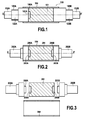
Fig. 1 is a schematic longitudinal section of a permanent magnet rotor shaft assembly for a high speed electrical machine according to a first embodiment of the invention; -
Fig. 2 is a schematic longitudinal section of a permanent magnet rotor shaft assembly for a high speed electrical machine according to a second embodiment of the invention; and -
Fig. 3 is a schematic exploded view of the permanent magnet rotor shaft assembly ofFig. 2 . - The present invention will be described in connection with preferred embodiments which are given by way of examples.
- A typical arrangement of a first embodiment of the invention is illustrated in
Fig. 1 which shows a permanentrotor shaft assembly 100 for an electrical machine, more specifically for high speed applications which can reach tip speeds up to 300 m/s. Theassembly 100 comprises a permanent magnetcylindrical core 101 having a longitudinal axis X-X'. Thecylindrical core 101 is axially compressed by first andsecond end shafts sleeve 104 made of a non-magnetic high strength metal. The set ofelements - According to the invention one (102A) of the first and
second end shafts cylindrical core 101, acentral shoulder head 103A which cooperates with a matingcentral recess 106A made in a central portion of a front face of thecylindrical core 101. - The
shoulder head 103A insures the concentricity of theelements cylindrical magnet core 101, whilst introducing additional stiffness to the set of assembledelements - The permanent magnet
cylindrical core 101 comprises rare earth magnets such as NdFeBr or Sm2Co17. - The
sleeve 104 is made of a non-magnetic high strength metal which may be advantageously chosen among Inconel, Hastelloy, Ti-6%Al-6%V-2%Sn, Ti-2.5%Cu. - The magnetization direction of the
magnet 101 may be radial, diametral or constituted by a Halbach magnetization. - The polarity of the magnets of the
core 101 can be 2 poles or 4 poles. - The
central shoulder head 103A is inserted in the mating central recess by tight fit assembly, slip joint assembly or glued assembly. - The first and
second end shafts sleeve 104 are fixed on the permanent magnetcylindrical core 101 by welding, adhesive or heat shrinking. - The
sleeve 104 constitutes a hoop which radially compresses the permanent magnetcylindrical core 101 and the first andsecond end shafts - The first and
second end shafts cylindrical core 101. - According to a specific embodiment, the first and
second end shafts cylindrical tracks - The
reference numerals second end shafts second end shafts - The tracks for mechanical bearings and/or the stack iron laminations for magnetic bearings may be located on a stepped
portion second end shafts elements -
Figs 2 and 3 illustrate a second embodiment of the invention which relates to a permanent rotor shaft assembly 200 for an electrical machine, more specifically for high speed applications which can reach tip speeds up to 300 m/s. The permanent rotor shaft assembly 200 comprises a permanent magnetcylindrical core 201 having a longitudinal axis X-X'. Thecylindrical core 201 is axially compressed by first andsecond end shafts sleeve 204 made of a non-magnetic high strength metal. The set ofelements assembly 100 of the first embodiment. - However in the permanent rotor shaft assembly 200 according to the second embodiment of
Figs 2 and 3 , acentral shoulder head second end shafts cylindrical core 201, a matingcentral recess cylindrical core 201, and the central shoulder heads 203A, 203B are respectively mounted in the matingcentral recesses iron laminations Fig. 1 may also be applied to the embodiment ofFig. 2 . The assembly 200 ofFig. 2 nevertheless constitutes a best mode of implementation of the invention and ensures an easy concentric alignment of theelements sleeve 204 and confers an enhanced stiffness on the set of elements once assembled. - The invention further relates to a method for making a permanent
rotor shaft assembly 100 or 200 for an electrical machine, comprising the steps of: - forming a permanent magnet
cylindrical core 101 respectively 201 having a longitudinal axis X-X', - bonding a
first end shaft 102A respectively 202A onto one end of the permanent magnetcylindrical core 101 respectively 201, - bonding a
second end shaft 102B respectively 202B onto the other end of the permanent magnetcylindrical core 101 respectively 201, - installing a
sleeve 104 respectively 204 made of a non-magnetic high strength metal in interference fit fashion around the permanent magnetcylindrical core 101 respectively 201 and the portions of the first andsecond end shafts cylindrical core 101 respectively 201, so that thecylindrical core 101 respectively 201 be axially compressed by the first andsecond end shafts sleeve 104 respectively 204. - More specifically, the method according to the invention further comprises the steps of:
- providing at least one
central shoulder head 103A respectively 203A, 203B in the first andsecond end shafts cylindrical core 101 respectively 201, - providing in a central portion of a front face of the
cylindrical core 101 respectively 201, at least one matingcentral recess 106A respectively 206A, 206B, which is adapted to cooperate with the at least onecentral shoulder head 103A respectively 203A, 203B, and - mounting the at least one
central shoulder head 103A respectively 203A, 203B in the at least one matingcentral recess 106A respectively 206A, 206B, before inserting thesleeve 104 respectively 204 made of a non-magnetic high strength metal in interference fit fashion around the permanent magnetcylindrical core 101 respectively 201 and the portions of the first andsecond end shafts cylindrical core 101 respectively 201. - In the preferred embodiment illustrated in
Figs 2 and 3 , acentral shoulder head second end shafts cylindrical core 201, a matingcentral recess cylindrical core 201, and the central shoulder heads 203A, 203B are respectively mounted in the matingcentral recesses sleeve 204 made of a non-magnetic high strength metal in interference fit fashion around the permanent magnetcylindrical core 201 and the portions of the first andsecond end shafts cylindrical core 201. - The
central shoulder head central recess - The first and
second end shafts sleeve 104 respectively 204 are preferably fixed to the permanent magnetcylindrical core 101 respectively 201 by welding, adhesive or heat shrinking. - Generally speaking, the invention provides a simplification in the manufacturing process, increases performance and reduces cost.
- Although preferred embodiments have been shown and described, it should be understood that any changes and modifications may be made therein without departing from the scope of the invention as defined in the appended claims. Thus the features of the different embodiments may be combined. In particular the stepped
portions Fig. 1 may be implemented in the embodiment ofFigs 2 and 3 .
Claims (15)
- A permanent rotor shaft assembly for an electrical machine, comprising a permanent magnet cylindrical core (101; 201) having a longitudinal axis, said cylindrical core (101; 201) being axially compressed by first and second end shafts (102A, 102B; 202A, 202B) and being radially compressed by a sleeve (104; 204) made of a non-magnetic high strength metal, characterized in that at least one (102A; 202A, 202B) of said first and second end shafts (102A, 102B; 202A, 202B) comprises, in its portion facing said cylindrical core (101; 201), a central shoulder head (103A; 203A, 203B) which cooperates with a mating central recess (106A; 206A, 206B) made in a central portion of a front face of said cylindrical core (101; 201).
- The permanent rotor shaft assembly according to claim 1, wherein said permanent magnet cylindrical core (101; 201) comprises rare earth magnets made of NdFeBr or Sm2Co17.
- The permanent rotor shaft assembly according to claim 1 or claim 2, wherein said sleeve (104; 204) is made of a non-magnetic high strength metal chosen among Inconel, Hastelloy, Ti-6%Al-6%V-2%Sn, Ti-2.5%Cu.
- The permanent rotor shaft assembly according to any one of claims 1 to 3, wherein said central shoulder head (103A; 203A, 203B) is inserted in said mating central recess (106A; 206A, 206B) by tight fit assembly, slip joint assembly or glued assembly.
- The permanent rotor shaft assembly according to any one of claims 1 to 4, wherein said first and second end shafts (102A, 102B; 202A, 202B) and said sleeve (104; 204) are fixed on said permanent magnet cylindrical core (101; 201) by welding, adhesive or heat shrinking.
- The permanent rotor shaft assembly according to any one of claims 1 to 5, wherein said first and second end shafts (102A, 102B; 202A, 202B) further comprise cylindrical tracks (105A, 105B) for mechanical bearings.
- The permanent rotor shaft assembly according to any one of claims 1 to 6, wherein said first and second end shafts (102A, 102B; 202A, 202B) further comprise cylindrical stack iron laminations (105A, 105B) for magnetic bearings.
- The permanent rotor shaft assembly according to claim 6, wherein said cylindrical tracks (105A, 105B) for mechanical bearings are located on a stepped portion (122A, 122B) of said first and second end shafts (102A, 102B; 202A, 202B).
- The permanent rotor shaft assembly according to claim 7, wherein said cylindrical stack iron laminations (105A, 105B) for magnetic bearings are located on a stepped portion (122A, 122B) of said first and second end shafts (102A, 102B; 202A, 202B).
- The permanent rotor shaft assembly according to any one of claims 1 to 9, wherein a central shoulder head (203A, 203B) is provided in each of said first and second end shafts (202A, 202B), in its portion facing said cylindrical core (201), a mating central recess (206A, 206B) is provided in each of the central portions of the front faces of said cylindrical core (201), and said central shoulder heads (203A, 203B) are respectively mounted in said mating central recesses (206A, 206B).
- A rotary high speed electrical machine having tip speeds up to 300 m/s, characterized in that it comprises a permanent rotor shaft assembly according to any one of claims 1 to 10.
- A method for making a permanent rotor shaft assembly for an electrical machine, comprising the steps of:forming a permanent magnet cylindrical core (101; 201) having a longitudinal axis,bonding a first end shaft (102A; 202A) onto one end of said permanent magnet cylindrical core (101; 201),bonding a second end shaft (102B; 202B) onto the other end of said permanent magnet cylindrical core (101; 201),installing a sleeve (104; 204) made of a non-magnetic high strength metal in interference fit fashion around said permanent magnet cylindrical core (101; 201) and the portions of said first and second end shafts (102A, 102B; 202A, 202B) adjacent to said permanent magnet cylindrical core (101; 201), so that said cylindrical core (101; 201) be axially compressed by said first and second end shafts (102A, 102B; 202A, 202B) and be radially compressed by said sleeve (104; 204),characterized in that it further comprises the steps of:providing at least one central shoulder head (103A; 203A, 203B) in said first and second end shafts (102A, 102B; 202A, 202B), in its portion facing said cylindrical core (101; 201),providing in a central portion of a front face of said cylindrical core (101; 201), at least one mating central recess (106A; 206A, 206B), which is adapted to cooperate with said at least one central shoulder head (103A; 203A, 203B), andmounting said at least one central shoulder head (103A; 203A, 203B) in said at least one mating central recess (106A; 206A, 206B), before inserting said sleeve (104; 204) made of a non-magnetic high strength metal in interference fit fashion around said permanent magnet cylindrical core (101; 201) and the portions of said first and second end shafts (102A, 102B; 202A, 202B) adjacent to said permanent magnet cylindrical core (101; 201).
- The method according to claim 12, wherein a central shoulder head (203A, 203B) is provided in each of said first and second end shafts (202A, 202B), in its portion facing said cylindrical core (201), a mating central recess (206A, 206B) is provided in each of the central portions of the front faces of said cylindrical core (201), and said central shoulder heads (203A, 203B) are respectively mounted in said mating central recesses (206A, 206B), before inserting said sleeve (204) made of a non-magnetic high strength metal in interference fit fashion around said permanent magnet cylindrical core (201) and the portions of said first and second end shafts (202A, 202B) adjacent to said permanent magnet cylindrical core (201).
- The method according to claim 12 or claim 13, wherein said central shoulder head (203A, 203B) is inserted in a mating central recess (206A, 206B) by tight fit assembly, slip joint assembly or glued assembly.
- The method according to any one of claims 12 to 14, wherein said first and second end shafts (102A, 102B; 202A, 202B) and said sleeve (104; 204) are fixed to said permanent magnet cylindrical core (101; 201) by welding, adhesive or heat shrinking.
Priority Applications (8)
| Application Number | Priority Date | Filing Date | Title |
|---|---|---|---|
| EP13306322.2A EP2854258B1 (en) | 2013-09-26 | 2013-09-26 | Permanent magnet rotor shaft assembly and method |
| CA2863690A CA2863690A1 (en) | 2013-09-26 | 2014-09-17 | Permanent magnet rotor shaft assembly and method |
| BR102014023737A BR102014023737A2 (en) | 2013-09-26 | 2014-09-24 | Permanent magnet rotor shaft method and unit |
| JP2014194849A JP2015070786A (en) | 2013-09-26 | 2014-09-25 | Permanent magnet rotor shaft assembly and method |
| CN201410499758.4A CN104518587A (en) | 2013-09-26 | 2014-09-26 | Permanent magnet rotor shaft assembly and method of manufacturing the same |
| CN202010736603.3A CN111884372A (en) | 2013-09-26 | 2014-09-26 | Permanent magnet rotor shaft assembly and method of making the same |
| US14/500,454 US9800108B2 (en) | 2013-09-26 | 2014-09-29 | Permanent magnet rotor shaft assembly and method |
| JP2019111971A JP6851428B2 (en) | 2013-09-26 | 2019-06-17 | Permanent magnet rotor shaft assembly and method |
Applications Claiming Priority (1)
| Application Number | Priority Date | Filing Date | Title |
|---|---|---|---|
| EP13306322.2A EP2854258B1 (en) | 2013-09-26 | 2013-09-26 | Permanent magnet rotor shaft assembly and method |
Publications (2)
| Publication Number | Publication Date |
|---|---|
| EP2854258A1 true EP2854258A1 (en) | 2015-04-01 |
| EP2854258B1 EP2854258B1 (en) | 2021-01-20 |
Family
ID=49326621
Family Applications (1)
| Application Number | Title | Priority Date | Filing Date |
|---|---|---|---|
| EP13306322.2A Active EP2854258B1 (en) | 2013-09-26 | 2013-09-26 | Permanent magnet rotor shaft assembly and method |
Country Status (6)
| Country | Link |
|---|---|
| US (1) | US9800108B2 (en) |
| EP (1) | EP2854258B1 (en) |
| JP (2) | JP2015070786A (en) |
| CN (2) | CN104518587A (en) |
| BR (1) | BR102014023737A2 (en) |
| CA (1) | CA2863690A1 (en) |
Cited By (3)
| Publication number | Priority date | Publication date | Assignee | Title |
|---|---|---|---|---|
| EP3249085A3 (en) * | 2016-05-24 | 2017-12-20 | Rieter Ingolstadt GmbH | Rotor shaft for a spinning rotor and spinning rotor with contactless mounting in a magnetic bearing assembly |
| FR3055754A1 (en) * | 2016-09-02 | 2018-03-09 | Danfoss Silicon Power Gmbh | ROTOR FOR A HIGH SPEED ELECTRIC MOTOR |
| EP3745565A4 (en) * | 2018-01-22 | 2021-03-17 | Gree Electric Appliances, Inc. of Zhuhai | ROTOR SHAFT ARRANGEMENT, ROTOR AND MOTOR |
Families Citing this family (32)
| Publication number | Priority date | Publication date | Assignee | Title |
|---|---|---|---|---|
| US10012263B2 (en) * | 2012-09-28 | 2018-07-03 | Abb Research, Ltd | Rotors for rotating machines with hollow fiber-reinforced composite shaft |
| CN106329768A (en) * | 2015-07-06 | 2017-01-11 | 上海鸣志电器股份有限公司 | Shaft-holding permanent magnet type inter-shaft cementation rotor structure of high-speed motor |
| CN105226872B (en) * | 2015-11-16 | 2017-12-05 | 珠海格力节能环保制冷技术研究中心有限公司 | The manufacture method of rotor axis of electric, motor and rotor axis of electric |
| CN105449920B (en) * | 2015-12-07 | 2018-08-07 | 珠海格力节能环保制冷技术研究中心有限公司 | A kind of magneto shaft and its installation method |
| CN106130221A (en) * | 2016-08-04 | 2016-11-16 | 珠海格力节能环保制冷技术研究中心有限公司 | Rotating shaft, the assembly method of rotating shaft, motor |
| CN106130223B (en) * | 2016-08-04 | 2018-12-07 | 珠海格力电器股份有限公司 | Rotating shaft, assembling method of rotating shaft and motor |
| TWI645655B (en) * | 2017-07-04 | 2018-12-21 | 建準電機工業股份有限公司 | Rotor of inner-rotor motor |
| CA176247S (en) * | 2017-08-01 | 2018-09-17 | Stas Inc | Rotor for molten metal processing machine |
| CN107327501A (en) * | 2017-08-09 | 2017-11-07 | 哈尔滨电气动力装备有限公司 | Canned motor pump motor rotor axle journal tube-in-tube structure |
| CN111033966B (en) * | 2017-08-16 | 2022-11-08 | 索尤若驱动有限及两合公司 | motor with rotor |
| KR101919711B1 (en) * | 2017-10-24 | 2018-11-16 | 엘지전자 주식회사 | Rotor assembly and highspeed rotary device comprising the same |
| JP6935342B2 (en) | 2018-01-31 | 2021-09-15 | ミネベアミツミ株式会社 | How to manufacture rotors, motors and rotors |
| US11757327B2 (en) | 2018-01-31 | 2023-09-12 | Minebea Mitsumi Inc. | Rotor, motor, and method for manufacturing rotor |
| JP6967987B2 (en) | 2018-01-31 | 2021-11-17 | ミネベアミツミ株式会社 | Rotor, motor and rotor manufacturing method |
| JP2020089228A (en) * | 2018-11-30 | 2020-06-04 | 株式会社明電舎 | Rotor of rotary electric machine and manufacturing method of the same |
| CN111371251A (en) * | 2018-12-25 | 2020-07-03 | 珠海格力电器股份有限公司 | Motor with spiral cooling type rotor and compressor |
| EP3694083A1 (en) | 2019-02-08 | 2020-08-12 | Portescap | High speed compact rotor having high magnetic field |
| CN110829708A (en) * | 2019-12-03 | 2020-02-21 | 扬州大学 | A low-power permanent magnet synchronous motor combined shaft with a magnetic suspension support structure |
| KR102798687B1 (en) * | 2020-01-22 | 2025-04-23 | 한화파워시스템 주식회사 | A rotor magnet installation structure and a method for installing rotor magnet |
| CN112152347A (en) * | 2020-09-23 | 2020-12-29 | 珠海格力电器股份有限公司 | Rotor structure, motor and air conditioner |
| CN112467903B (en) * | 2020-11-23 | 2024-12-13 | 珠海格力电器股份有限公司 | Motor rotors and permanent magnet motors |
| JP2024012730A (en) * | 2020-12-17 | 2024-01-31 | 株式会社Ihi | Manufacturing method of rotor |
| JP7413990B2 (en) * | 2020-12-21 | 2024-01-16 | 株式会社豊田自動織機 | Rotating electric machine rotor |
| US20230412044A1 (en) * | 2020-12-24 | 2023-12-21 | Citizen Chiba Precision Co., Ltd. | Rotor, brushless motor, and method for manufacturing rotor |
| US11722025B2 (en) * | 2020-12-31 | 2023-08-08 | Trane International Inc. | Rotor for electric motors |
| CN113489185A (en) * | 2021-07-07 | 2021-10-08 | 鑫磊压缩机股份有限公司 | Motor rotor, magnetic steel assembling tool and method and hydrogen energy compressor |
| US11979062B2 (en) * | 2021-12-22 | 2024-05-07 | Garrett Transportation I Inc | Rotor assembly for turbomachine having electric motor with solitary solid core permanent magnet |
| WO2023188430A1 (en) * | 2022-04-01 | 2023-10-05 | 三菱電機株式会社 | Galvanometer scanner |
| CN114704499A (en) * | 2022-04-24 | 2022-07-05 | 珠海格力电器股份有限公司 | A rotor assembly and air circulation machine |
| CN115467852A (en) * | 2022-10-19 | 2022-12-13 | 河北金士顿科技有限责任公司 | Rotor shafting structure, rotor assembly and air compressor |
| US12506380B2 (en) * | 2023-06-24 | 2025-12-23 | Scott C. Mancl | Bearing seal for motors |
| DE102023211602A1 (en) * | 2023-11-22 | 2025-05-22 | Robert Bosch Gesellschaft mit beschränkter Haftung | Rotor for an electric machine |
Citations (8)
| Publication number | Priority date | Publication date | Assignee | Title |
|---|---|---|---|---|
| US3112417A (en) * | 1962-04-18 | 1963-11-26 | Baldor Electric Co | Bearing seal for electric motor |
| DE1938162U (en) * | 1966-03-10 | 1966-05-12 | Heinz Ahlswede | OXYD MAGNET RUNNER FOR OXYD RUNNER MOTORS. |
| US4617726A (en) * | 1984-12-06 | 1986-10-21 | The Garrett Corporation | Maximum stiffness permanent magnet rotor and construction method |
| US4741094A (en) | 1985-11-20 | 1988-05-03 | The Garrett Corporation | Two pole permanent magnet rotor construction method |
| WO1998034324A1 (en) | 1997-01-29 | 1998-08-06 | Turbocorp Limited | Improvements in high speed rotor shafts |
| US6104115A (en) | 1998-10-21 | 2000-08-15 | Technische Universiteit Eindhoven | Method for fabricating a permanent magnet rotor, and rotor obtained by said method |
| US20040189126A1 (en) * | 2001-09-06 | 2004-09-30 | Maurice Brunet | Modular system for suspending and rotating a rotary shaft |
| US7042118B2 (en) | 2003-11-10 | 2006-05-09 | Calnetix | Permanent magnet rotor construction wherein relative movement between components is prevented |
Family Cites Families (11)
| Publication number | Priority date | Publication date | Assignee | Title |
|---|---|---|---|---|
| JPS58163255A (en) * | 1982-03-24 | 1983-09-28 | Okuma Mach Works Ltd | Rotor for permanent magnet type synchronous motor |
| JPS62119182U (en) * | 1985-09-07 | 1987-07-29 | ||
| DE3807810C1 (en) * | 1988-03-10 | 1989-09-14 | Philips Patentverwaltung Gmbh, 2000 Hamburg, De | |
| US5936324A (en) * | 1998-03-30 | 1999-08-10 | Genetic Microsystems Inc. | Moving magnet scanner |
| US7365464B2 (en) * | 2003-09-05 | 2008-04-29 | Gsi Group Corporation | Composite rotor and output shaft for galvanometer motor and method of manufacture thereof |
| JP4591112B2 (en) * | 2005-02-25 | 2010-12-01 | 株式会社日立製作所 | Permanent magnet rotating machine |
| JP2009072036A (en) * | 2007-09-18 | 2009-04-02 | Meidensha Corp | Rotor structure of permanent-magnet rotating machine |
| US20110062812A1 (en) * | 2008-06-25 | 2011-03-17 | Alex Horng | Rotor Structure Including Fixing Seats Securely Coupling A Shaft and A Magnet Together |
| DE102010023813A1 (en) * | 2010-06-15 | 2011-12-15 | Maxon Motor Ag | Small electric motor |
| JP2013128359A (en) * | 2011-12-19 | 2013-06-27 | Honda Motor Co Ltd | Rotor and manufacturing method of the same |
| CN102570664A (en) * | 2012-01-19 | 2012-07-11 | 苏州正澳电器有限公司 | Motor rotor and method for machining same |
-
2013
- 2013-09-26 EP EP13306322.2A patent/EP2854258B1/en active Active
-
2014
- 2014-09-17 CA CA2863690A patent/CA2863690A1/en not_active Abandoned
- 2014-09-24 BR BR102014023737A patent/BR102014023737A2/en not_active Application Discontinuation
- 2014-09-25 JP JP2014194849A patent/JP2015070786A/en active Pending
- 2014-09-26 CN CN201410499758.4A patent/CN104518587A/en active Pending
- 2014-09-26 CN CN202010736603.3A patent/CN111884372A/en active Pending
- 2014-09-29 US US14/500,454 patent/US9800108B2/en active Active
-
2019
- 2019-06-17 JP JP2019111971A patent/JP6851428B2/en active Active
Patent Citations (8)
| Publication number | Priority date | Publication date | Assignee | Title |
|---|---|---|---|---|
| US3112417A (en) * | 1962-04-18 | 1963-11-26 | Baldor Electric Co | Bearing seal for electric motor |
| DE1938162U (en) * | 1966-03-10 | 1966-05-12 | Heinz Ahlswede | OXYD MAGNET RUNNER FOR OXYD RUNNER MOTORS. |
| US4617726A (en) * | 1984-12-06 | 1986-10-21 | The Garrett Corporation | Maximum stiffness permanent magnet rotor and construction method |
| US4741094A (en) | 1985-11-20 | 1988-05-03 | The Garrett Corporation | Two pole permanent magnet rotor construction method |
| WO1998034324A1 (en) | 1997-01-29 | 1998-08-06 | Turbocorp Limited | Improvements in high speed rotor shafts |
| US6104115A (en) | 1998-10-21 | 2000-08-15 | Technische Universiteit Eindhoven | Method for fabricating a permanent magnet rotor, and rotor obtained by said method |
| US20040189126A1 (en) * | 2001-09-06 | 2004-09-30 | Maurice Brunet | Modular system for suspending and rotating a rotary shaft |
| US7042118B2 (en) | 2003-11-10 | 2006-05-09 | Calnetix | Permanent magnet rotor construction wherein relative movement between components is prevented |
Cited By (4)
| Publication number | Priority date | Publication date | Assignee | Title |
|---|---|---|---|---|
| EP3249085A3 (en) * | 2016-05-24 | 2017-12-20 | Rieter Ingolstadt GmbH | Rotor shaft for a spinning rotor and spinning rotor with contactless mounting in a magnetic bearing assembly |
| FR3055754A1 (en) * | 2016-09-02 | 2018-03-09 | Danfoss Silicon Power Gmbh | ROTOR FOR A HIGH SPEED ELECTRIC MOTOR |
| EP3745565A4 (en) * | 2018-01-22 | 2021-03-17 | Gree Electric Appliances, Inc. of Zhuhai | ROTOR SHAFT ARRANGEMENT, ROTOR AND MOTOR |
| US11735976B2 (en) | 2018-01-22 | 2023-08-22 | Gree Electric Appliances, Inc. Of Zhuhai | Rotor shaft assembly, rotor and motor |
Also Published As
| Publication number | Publication date |
|---|---|
| JP2015070786A (en) | 2015-04-13 |
| EP2854258B1 (en) | 2021-01-20 |
| US20150084464A1 (en) | 2015-03-26 |
| CN104518587A (en) | 2015-04-15 |
| CA2863690A1 (en) | 2015-03-26 |
| BR102014023737A2 (en) | 2016-05-24 |
| JP2019176731A (en) | 2019-10-10 |
| CN111884372A (en) | 2020-11-03 |
| JP6851428B2 (en) | 2021-03-31 |
| US9800108B2 (en) | 2017-10-24 |
Similar Documents
| Publication | Publication Date | Title |
|---|---|---|
| EP2854258B1 (en) | Permanent magnet rotor shaft assembly and method | |
| CN103259355A (en) | Rotor of electric motor having structure for attaching magnet securely to outer circumferential surface of rotor core and manufacturing method thereof | |
| US6711805B2 (en) | Process for the production of a rotor, containing permanent magnets, of a synchronous machine, and rotor produced according to this process | |
| US9866077B2 (en) | Rotor and reluctance motor | |
| US9935508B2 (en) | Individual-segment rotor having individual segments retained by flexural supports and production method | |
| US9667109B2 (en) | Permanent magnet electrical machine rotors with stacked annular magnets and retainers and construction methods therefor | |
| US8786157B2 (en) | Separable tooth tip armature construction | |
| WO2010039786A3 (en) | Electric machine | |
| CN105245043B (en) | A segmented inclined pole permanent magnet synchronous motor rotor | |
| US20200381962A1 (en) | Electrical machines | |
| JP2009077469A (en) | Internal magnet type motor and manufacturing method thereof | |
| US7638913B2 (en) | Rotor core with spacers | |
| US8304948B2 (en) | Rotor structure for a permanent magnet electrical machine | |
| EP3469695B1 (en) | Retention sleeve and balance strategy for a high speed permanent magnet rotor | |
| CA2655819A1 (en) | Inductor-type synchronous machine | |
| US9641030B2 (en) | Methods of manufacturing rotors having interfering sintered magnets and carbon filament sheaths for electric motors | |
| CN107630270B (en) | Rotor shaft of magnetic suspension bearing structure spinning rotor and corresponding spinning rotor | |
| CN105915004A (en) | Rotor of motor | |
| KR20170128458A (en) | An outer rotor electric machine having SMC blocks sandwiched between permanent magnets | |
| JP2016220492A (en) | Rotor, rotary machine and manufacturing method for rotor | |
| JP2007267574A (en) | Rotor manufacturing method and electric power steering motor | |
| CN106877612A (en) | A kind of rotor structure of permagnetic synchronous motor | |
| EP3496232A1 (en) | Permanent magnet for a permanent magnet machine | |
| JP2007053864A (en) | Permanent magnet embedded rotor | |
| JP6155574B2 (en) | Permanent magnet motor, rotor structure, and method of manufacturing rotor structure |
Legal Events
| Date | Code | Title | Description |
|---|---|---|---|
| PUAI | Public reference made under article 153(3) epc to a published international application that has entered the european phase |
Free format text: ORIGINAL CODE: 0009012 |
|
| 17P | Request for examination filed |
Effective date: 20130926 |
|
| AK | Designated contracting states |
Kind code of ref document: A1 Designated state(s): AL AT BE BG CH CY CZ DE DK EE ES FI FR GB GR HR HU IE IS IT LI LT LU LV MC MK MT NL NO PL PT RO RS SE SI SK SM TR |
|
| AX | Request for extension of the european patent |
Extension state: BA ME |
|
| R17P | Request for examination filed (corrected) |
Effective date: 20150929 |
|
| RBV | Designated contracting states (corrected) |
Designated state(s): AL AT BE BG CH CY CZ DE DK EE ES FI FR GB GR HR HU IE IS IT LI LT LU LV MC MK MT NL NO PL PT RO RS SE SI SK SM TR |
|
| 17Q | First examination report despatched |
Effective date: 20160812 |
|
| STAA | Information on the status of an ep patent application or granted ep patent |
Free format text: STATUS: EXAMINATION IS IN PROGRESS |
|
| GRAP | Despatch of communication of intention to grant a patent |
Free format text: ORIGINAL CODE: EPIDOSNIGR1 |
|
| STAA | Information on the status of an ep patent application or granted ep patent |
Free format text: STATUS: GRANT OF PATENT IS INTENDED |
|
| INTG | Intention to grant announced |
Effective date: 20200824 |
|
| GRAS | Grant fee paid |
Free format text: ORIGINAL CODE: EPIDOSNIGR3 |
|
| GRAA | (expected) grant |
Free format text: ORIGINAL CODE: 0009210 |
|
| STAA | Information on the status of an ep patent application or granted ep patent |
Free format text: STATUS: THE PATENT HAS BEEN GRANTED |
|
| AK | Designated contracting states |
Kind code of ref document: B1 Designated state(s): AL AT BE BG CH CY CZ DE DK EE ES FI FR GB GR HR HU IE IS IT LI LT LU LV MC MK MT NL NO PL PT RO RS SE SI SK SM TR |
|
| REG | Reference to a national code |
Ref country code: GB Ref legal event code: FG4D |
|
| REG | Reference to a national code |
Ref country code: CH Ref legal event code: EP |
|
| REG | Reference to a national code |
Ref country code: DE Ref legal event code: R096 Ref document number: 602013075371 Country of ref document: DE |
|
| REG | Reference to a national code |
Ref country code: AT Ref legal event code: REF Ref document number: 1357194 Country of ref document: AT Kind code of ref document: T Effective date: 20210215 |
|
| REG | Reference to a national code |
Ref country code: IE Ref legal event code: FG4D |
|
| REG | Reference to a national code |
Ref country code: NL Ref legal event code: MP Effective date: 20210120 |
|
| REG | Reference to a national code |
Ref country code: LT Ref legal event code: MG9D |
|
| REG | Reference to a national code |
Ref country code: AT Ref legal event code: MK05 Ref document number: 1357194 Country of ref document: AT Kind code of ref document: T Effective date: 20210120 |
|
| PG25 | Lapsed in a contracting state [announced via postgrant information from national office to epo] |
Ref country code: LT Free format text: LAPSE BECAUSE OF FAILURE TO SUBMIT A TRANSLATION OF THE DESCRIPTION OR TO PAY THE FEE WITHIN THE PRESCRIBED TIME-LIMIT Effective date: 20210120 Ref country code: PT Free format text: LAPSE BECAUSE OF FAILURE TO SUBMIT A TRANSLATION OF THE DESCRIPTION OR TO PAY THE FEE WITHIN THE PRESCRIBED TIME-LIMIT Effective date: 20210520 Ref country code: HR Free format text: LAPSE BECAUSE OF FAILURE TO SUBMIT A TRANSLATION OF THE DESCRIPTION OR TO PAY THE FEE WITHIN THE PRESCRIBED TIME-LIMIT Effective date: 20210120 Ref country code: FI Free format text: LAPSE BECAUSE OF FAILURE TO SUBMIT A TRANSLATION OF THE DESCRIPTION OR TO PAY THE FEE WITHIN THE PRESCRIBED TIME-LIMIT Effective date: 20210120 Ref country code: GR Free format text: LAPSE BECAUSE OF FAILURE TO SUBMIT A TRANSLATION OF THE DESCRIPTION OR TO PAY THE FEE WITHIN THE PRESCRIBED TIME-LIMIT Effective date: 20210421 Ref country code: BG Free format text: LAPSE BECAUSE OF FAILURE TO SUBMIT A TRANSLATION OF THE DESCRIPTION OR TO PAY THE FEE WITHIN THE PRESCRIBED TIME-LIMIT Effective date: 20210420 Ref country code: NL Free format text: LAPSE BECAUSE OF FAILURE TO SUBMIT A TRANSLATION OF THE DESCRIPTION OR TO PAY THE FEE WITHIN THE PRESCRIBED TIME-LIMIT Effective date: 20210120 Ref country code: NO Free format text: LAPSE BECAUSE OF FAILURE TO SUBMIT A TRANSLATION OF THE DESCRIPTION OR TO PAY THE FEE WITHIN THE PRESCRIBED TIME-LIMIT Effective date: 20210420 |
|
| PG25 | Lapsed in a contracting state [announced via postgrant information from national office to epo] |
Ref country code: RS Free format text: LAPSE BECAUSE OF FAILURE TO SUBMIT A TRANSLATION OF THE DESCRIPTION OR TO PAY THE FEE WITHIN THE PRESCRIBED TIME-LIMIT Effective date: 20210120 Ref country code: LV Free format text: LAPSE BECAUSE OF FAILURE TO SUBMIT A TRANSLATION OF THE DESCRIPTION OR TO PAY THE FEE WITHIN THE PRESCRIBED TIME-LIMIT Effective date: 20210120 Ref country code: PL Free format text: LAPSE BECAUSE OF FAILURE TO SUBMIT A TRANSLATION OF THE DESCRIPTION OR TO PAY THE FEE WITHIN THE PRESCRIBED TIME-LIMIT Effective date: 20210120 Ref country code: AT Free format text: LAPSE BECAUSE OF FAILURE TO SUBMIT A TRANSLATION OF THE DESCRIPTION OR TO PAY THE FEE WITHIN THE PRESCRIBED TIME-LIMIT Effective date: 20210120 Ref country code: SE Free format text: LAPSE BECAUSE OF FAILURE TO SUBMIT A TRANSLATION OF THE DESCRIPTION OR TO PAY THE FEE WITHIN THE PRESCRIBED TIME-LIMIT Effective date: 20210120 |
|
| PG25 | Lapsed in a contracting state [announced via postgrant information from national office to epo] |
Ref country code: IS Free format text: LAPSE BECAUSE OF FAILURE TO SUBMIT A TRANSLATION OF THE DESCRIPTION OR TO PAY THE FEE WITHIN THE PRESCRIBED TIME-LIMIT Effective date: 20210520 |
|
| REG | Reference to a national code |
Ref country code: DE Ref legal event code: R097 Ref document number: 602013075371 Country of ref document: DE |
|
| PG25 | Lapsed in a contracting state [announced via postgrant information from national office to epo] |
Ref country code: SM Free format text: LAPSE BECAUSE OF FAILURE TO SUBMIT A TRANSLATION OF THE DESCRIPTION OR TO PAY THE FEE WITHIN THE PRESCRIBED TIME-LIMIT Effective date: 20210120 Ref country code: EE Free format text: LAPSE BECAUSE OF FAILURE TO SUBMIT A TRANSLATION OF THE DESCRIPTION OR TO PAY THE FEE WITHIN THE PRESCRIBED TIME-LIMIT Effective date: 20210120 Ref country code: CZ Free format text: LAPSE BECAUSE OF FAILURE TO SUBMIT A TRANSLATION OF THE DESCRIPTION OR TO PAY THE FEE WITHIN THE PRESCRIBED TIME-LIMIT Effective date: 20210120 |
|
| PLBE | No opposition filed within time limit |
Free format text: ORIGINAL CODE: 0009261 |
|
| STAA | Information on the status of an ep patent application or granted ep patent |
Free format text: STATUS: NO OPPOSITION FILED WITHIN TIME LIMIT |
|
| PG25 | Lapsed in a contracting state [announced via postgrant information from national office to epo] |
Ref country code: ES Free format text: LAPSE BECAUSE OF FAILURE TO SUBMIT A TRANSLATION OF THE DESCRIPTION OR TO PAY THE FEE WITHIN THE PRESCRIBED TIME-LIMIT Effective date: 20210120 Ref country code: DK Free format text: LAPSE BECAUSE OF FAILURE TO SUBMIT A TRANSLATION OF THE DESCRIPTION OR TO PAY THE FEE WITHIN THE PRESCRIBED TIME-LIMIT Effective date: 20210120 Ref country code: SK Free format text: LAPSE BECAUSE OF FAILURE TO SUBMIT A TRANSLATION OF THE DESCRIPTION OR TO PAY THE FEE WITHIN THE PRESCRIBED TIME-LIMIT Effective date: 20210120 Ref country code: RO Free format text: LAPSE BECAUSE OF FAILURE TO SUBMIT A TRANSLATION OF THE DESCRIPTION OR TO PAY THE FEE WITHIN THE PRESCRIBED TIME-LIMIT Effective date: 20210120 |
|
| 26N | No opposition filed |
Effective date: 20211021 |
|
| PG25 | Lapsed in a contracting state [announced via postgrant information from national office to epo] |
Ref country code: AL Free format text: LAPSE BECAUSE OF FAILURE TO SUBMIT A TRANSLATION OF THE DESCRIPTION OR TO PAY THE FEE WITHIN THE PRESCRIBED TIME-LIMIT Effective date: 20210120 |
|
| PG25 | Lapsed in a contracting state [announced via postgrant information from national office to epo] |
Ref country code: SI Free format text: LAPSE BECAUSE OF FAILURE TO SUBMIT A TRANSLATION OF THE DESCRIPTION OR TO PAY THE FEE WITHIN THE PRESCRIBED TIME-LIMIT Effective date: 20210120 |
|
| REG | Reference to a national code |
Ref country code: DE Ref legal event code: R119 Ref document number: 602013075371 Country of ref document: DE |
|
| PG25 | Lapsed in a contracting state [announced via postgrant information from national office to epo] |
Ref country code: IT Free format text: LAPSE BECAUSE OF FAILURE TO SUBMIT A TRANSLATION OF THE DESCRIPTION OR TO PAY THE FEE WITHIN THE PRESCRIBED TIME-LIMIT Effective date: 20210120 |
|
| REG | Reference to a national code |
Ref country code: CH Ref legal event code: PL |
|
| REG | Reference to a national code |
Ref country code: BE Ref legal event code: MM Effective date: 20210930 |
|
| GBPC | Gb: european patent ceased through non-payment of renewal fee |
Effective date: 20210926 |
|
| PG25 | Lapsed in a contracting state [announced via postgrant information from national office to epo] |
Ref country code: IS Free format text: LAPSE BECAUSE OF FAILURE TO SUBMIT A TRANSLATION OF THE DESCRIPTION OR TO PAY THE FEE WITHIN THE PRESCRIBED TIME-LIMIT Effective date: 20210520 Ref country code: MC Free format text: LAPSE BECAUSE OF FAILURE TO SUBMIT A TRANSLATION OF THE DESCRIPTION OR TO PAY THE FEE WITHIN THE PRESCRIBED TIME-LIMIT Effective date: 20210120 |
|
| PG25 | Lapsed in a contracting state [announced via postgrant information from national office to epo] |
Ref country code: LU Free format text: LAPSE BECAUSE OF NON-PAYMENT OF DUE FEES Effective date: 20210926 Ref country code: IE Free format text: LAPSE BECAUSE OF NON-PAYMENT OF DUE FEES Effective date: 20210926 Ref country code: GB Free format text: LAPSE BECAUSE OF NON-PAYMENT OF DUE FEES Effective date: 20210926 Ref country code: DE Free format text: LAPSE BECAUSE OF NON-PAYMENT OF DUE FEES Effective date: 20220401 Ref country code: BE Free format text: LAPSE BECAUSE OF NON-PAYMENT OF DUE FEES Effective date: 20210930 |
|
| PG25 | Lapsed in a contracting state [announced via postgrant information from national office to epo] |
Ref country code: LI Free format text: LAPSE BECAUSE OF NON-PAYMENT OF DUE FEES Effective date: 20210930 Ref country code: CH Free format text: LAPSE BECAUSE OF NON-PAYMENT OF DUE FEES Effective date: 20210930 |
|
| PG25 | Lapsed in a contracting state [announced via postgrant information from national office to epo] |
Ref country code: HU Free format text: LAPSE BECAUSE OF FAILURE TO SUBMIT A TRANSLATION OF THE DESCRIPTION OR TO PAY THE FEE WITHIN THE PRESCRIBED TIME-LIMIT; INVALID AB INITIO Effective date: 20130926 |
|
| P01 | Opt-out of the competence of the unified patent court (upc) registered |
Effective date: 20230514 |
|
| PG25 | Lapsed in a contracting state [announced via postgrant information from national office to epo] |
Ref country code: CY Free format text: LAPSE BECAUSE OF FAILURE TO SUBMIT A TRANSLATION OF THE DESCRIPTION OR TO PAY THE FEE WITHIN THE PRESCRIBED TIME-LIMIT Effective date: 20210120 |
|
| PG25 | Lapsed in a contracting state [announced via postgrant information from national office to epo] |
Ref country code: MK Free format text: LAPSE BECAUSE OF FAILURE TO SUBMIT A TRANSLATION OF THE DESCRIPTION OR TO PAY THE FEE WITHIN THE PRESCRIBED TIME-LIMIT Effective date: 20210120 |
|
| PG25 | Lapsed in a contracting state [announced via postgrant information from national office to epo] |
Ref country code: MT Free format text: LAPSE BECAUSE OF FAILURE TO SUBMIT A TRANSLATION OF THE DESCRIPTION OR TO PAY THE FEE WITHIN THE PRESCRIBED TIME-LIMIT Effective date: 20210120 |
|
| PGFP | Annual fee paid to national office [announced via postgrant information from national office to epo] |
Ref country code: FR Payment date: 20250925 Year of fee payment: 13 |
|
| PG25 | Lapsed in a contracting state [announced via postgrant information from national office to epo] |
Ref country code: TR Free format text: LAPSE BECAUSE OF FAILURE TO SUBMIT A TRANSLATION OF THE DESCRIPTION OR TO PAY THE FEE WITHIN THE PRESCRIBED TIME-LIMIT Effective date: 20210120 |