EP2854225A1 - Lead wire connection structure and electronic device including the same - Google Patents
Lead wire connection structure and electronic device including the same Download PDFInfo
- Publication number
- EP2854225A1 EP2854225A1 EP14180039.1A EP14180039A EP2854225A1 EP 2854225 A1 EP2854225 A1 EP 2854225A1 EP 14180039 A EP14180039 A EP 14180039A EP 2854225 A1 EP2854225 A1 EP 2854225A1
- Authority
- EP
- European Patent Office
- Prior art keywords
- nut
- lead wire
- connection structure
- wire connection
- terminal
- Prior art date
- Legal status (The legal status is an assumption and is not a legal conclusion. Google has not performed a legal analysis and makes no representation as to the accuracy of the status listed.)
- Withdrawn
Links
Images









Classifications
-
- H—ELECTRICITY
- H01—ELECTRIC ELEMENTS
- H01R—ELECTRICALLY-CONDUCTIVE CONNECTIONS; STRUCTURAL ASSOCIATIONS OF A PLURALITY OF MUTUALLY-INSULATED ELECTRICAL CONNECTING ELEMENTS; COUPLING DEVICES; CURRENT COLLECTORS
- H01R13/00—Details of coupling devices of the kinds covered by groups H01R12/70 or H01R24/00 - H01R33/00
- H01R13/62—Means for facilitating engagement or disengagement of coupling parts or for holding them in engagement
- H01R13/627—Snap or like fastening
-
- H—ELECTRICITY
- H01—ELECTRIC ELEMENTS
- H01R—ELECTRICALLY-CONDUCTIVE CONNECTIONS; STRUCTURAL ASSOCIATIONS OF A PLURALITY OF MUTUALLY-INSULATED ELECTRICAL CONNECTING ELEMENTS; COUPLING DEVICES; CURRENT COLLECTORS
- H01R13/00—Details of coupling devices of the kinds covered by groups H01R12/70 or H01R24/00 - H01R33/00
- H01R13/02—Contact members
- H01R13/025—Contact members formed by the conductors of a cable end
-
- H—ELECTRICITY
- H01—ELECTRIC ELEMENTS
- H01R—ELECTRICALLY-CONDUCTIVE CONNECTIONS; STRUCTURAL ASSOCIATIONS OF A PLURALITY OF MUTUALLY-INSULATED ELECTRICAL CONNECTING ELEMENTS; COUPLING DEVICES; CURRENT COLLECTORS
- H01R4/00—Electrically-conductive connections between two or more conductive members in direct contact, i.e. touching one another; Means for effecting or maintaining such contact; Electrically-conductive connections having two or more spaced connecting locations for conductors and using contact members penetrating insulation
- H01R4/28—Clamped connections, spring connections
- H01R4/30—Clamped connections, spring connections utilising a screw or nut clamping member
- H01R4/302—Clamped connections, spring connections utilising a screw or nut clamping member having means for preventing loosening of screw or nut, e.g. vibration-proof connection
-
- H—ELECTRICITY
- H01—ELECTRIC ELEMENTS
- H01R—ELECTRICALLY-CONDUCTIVE CONNECTIONS; STRUCTURAL ASSOCIATIONS OF A PLURALITY OF MUTUALLY-INSULATED ELECTRICAL CONNECTING ELEMENTS; COUPLING DEVICES; CURRENT COLLECTORS
- H01R33/00—Coupling devices specially adapted for supporting apparatus and having one part acting as a holder providing support and electrical connection via a counterpart which is structurally associated with the apparatus, e.g. lamp holders; Separate parts thereof
- H01R33/74—Devices having four or more poles, e.g. holders for compact fluorescent lamps
- H01R33/76—Holders with sockets, clips, or analogous contacts adapted for axially-sliding engagement with parallely-arranged pins, blades, or analogous contacts on counterpart, e.g. electronic tube socket
-
- H—ELECTRICITY
- H01—ELECTRIC ELEMENTS
- H01R—ELECTRICALLY-CONDUCTIVE CONNECTIONS; STRUCTURAL ASSOCIATIONS OF A PLURALITY OF MUTUALLY-INSULATED ELECTRICAL CONNECTING ELEMENTS; COUPLING DEVICES; CURRENT COLLECTORS
- H01R33/00—Coupling devices specially adapted for supporting apparatus and having one part acting as a holder providing support and electrical connection via a counterpart which is structurally associated with the apparatus, e.g. lamp holders; Separate parts thereof
- H01R33/74—Devices having four or more poles, e.g. holders for compact fluorescent lamps
- H01R33/76—Holders with sockets, clips, or analogous contacts adapted for axially-sliding engagement with parallely-arranged pins, blades, or analogous contacts on counterpart, e.g. electronic tube socket
- H01R33/7685—Holders with sockets, clips, or analogous contacts adapted for axially-sliding engagement with parallely-arranged pins, blades, or analogous contacts on counterpart, e.g. electronic tube socket having internal socket contact by abutting
-
- H—ELECTRICITY
- H01—ELECTRIC ELEMENTS
- H01R—ELECTRICALLY-CONDUCTIVE CONNECTIONS; STRUCTURAL ASSOCIATIONS OF A PLURALITY OF MUTUALLY-INSULATED ELECTRICAL CONNECTING ELEMENTS; COUPLING DEVICES; CURRENT COLLECTORS
- H01R4/00—Electrically-conductive connections between two or more conductive members in direct contact, i.e. touching one another; Means for effecting or maintaining such contact; Electrically-conductive connections having two or more spaced connecting locations for conductors and using contact members penetrating insulation
- H01R4/28—Clamped connections, spring connections
- H01R4/30—Clamped connections, spring connections utilising a screw or nut clamping member
-
- F—MECHANICAL ENGINEERING; LIGHTING; HEATING; WEAPONS; BLASTING
- F16—ENGINEERING ELEMENTS AND UNITS; GENERAL MEASURES FOR PRODUCING AND MAINTAINING EFFECTIVE FUNCTIONING OF MACHINES OR INSTALLATIONS; THERMAL INSULATION IN GENERAL
- F16B—DEVICES FOR FASTENING OR SECURING CONSTRUCTIONAL ELEMENTS OR MACHINE PARTS TOGETHER, e.g. NAILS, BOLTS, CIRCLIPS, CLAMPS, CLIPS OR WEDGES; JOINTS OR JOINTING
- F16B37/00—Nuts or like thread-engaging members
- F16B37/04—Devices for fastening nuts to surfaces, e.g. sheets, plates
- F16B37/044—Nut cages
Definitions
- an object of the disclosure is to provide a lead wire connection structure obtained at low manufacturing cost, that is, a lead wire connection structure obtained in a short processing time at low material cost and manufacturing facility cost.
- the nut is held by the elastic holding parts of the terminal. Therefore, burring does not need to be performed, and the connection part of the terminal is easily bent while screw tightening torque is ensured.
- the lead wire connection structure is obtained at low manufacturing cost, that is, the lead wire connection structure is obtained in a short processing time at low material cost and manufacturing facility cost.
- the terminal main body when the nut is formed into a quadrilateral shape as seen in a planar view, a bottom surface of the terminal main body can be entirely supported with the nut, so that an area supported with the nut is widened. Therefore, since the terminal main body is not plastically deformed in a thickness direction, the terminal can be entirely formed of a thinner metal material, so that material cost can be saved.
- the nut may have chamfered portions formed on at least a pair of edges of the opposite side surfaces thereof, the edges being opposite to each other with the internal thread hole interposed therebetween.
- the elastic holding parts of the terminal are easily attached to the nut. Therefore, assembling workability is improved.
- the nut may have an annular chamfered portion formed along an opening edge of the internal thread hole thereof, and the terminal main body may have a through hole having a diameter which is equal to or more than an outer peripheral diameter of the annular chamfered portion.
- the screw is guided by the annular chamfered portion and is easily screwed into the internal thread hole.
- the terminal and the nut may be held by an inner surface of the cover and a support plate protruding from a top surface of the base.
- the cover 20 is positioned with the opening thereof directed upward. Then, the inverted screw 50 having a washer 51 attached thereto is inserted into the space formed by the insulation walls 23 and 23, the rearward partition wall 24 and the forward partition wall 25.
- a head of the screw 50 is fitted into the work hole 26a of the finger protector 26, and the washer 51 is locked by an opening edge of the work hole 26a, so that the screw 50 is positioned. Therefore, the assembling work is facilitated.
- the terminal 80 and the nut 90 each connected to the lead wire 60 are temporarily fixed in the space formed by the insulation walls 23 and 23, the rearward partition wall 24 and the forward partition wall 25.
- the connection part 85 of the terminal 80 is engaged with the notch 24a of the rearward partition wall 24, and the inward surface of the nut 90 is brought into contact with the rearward partition wall 24, so that the nut 90 is positioned.
- both side surfaces of the nut 90 are positioned by the insulation walls 23 and 23 through the use of the elastic holding parts 83 and the positioning tongue pieces 84.
- the lead wire 60 is easily bent, the assembling work is facilitated.
- the elastic holding parts 83 of the terminal 80 hold the nut 90 such that the nut 90 is prevented from dropping off. Therefore, the assembling work is further facilitated.
- the third embodiment is almost equal to the first embodiment, but is different from the first embodiment in the following point. That is, engagement grooves 92 are formed on opposite outer side surfaces of the nut 90 so as to cut through the outer side surfaces, and the terminal 80 holds the nut 90 in such a manner that the elastic holding parts 83 are engaged with the engagement grooves 92.
- the same constituent components are denoted with the same reference signs, and the detailed description thereof will not be given here.
- the nut 90 can be more accurately and firmly held, and therefore is still less prone to drop off.
Landscapes
- Connections Arranged To Contact A Plurality Of Conductors (AREA)
- Connections By Means Of Piercing Elements, Nuts, Or Screws (AREA)
Abstract
Description
- This application is based on Japanese Patent Application No.
2013-201848 - The disclosure relates to a lead wire connection structure, for example, a lead wire connection structure to be incorporated in a relay socket.
- Heretofore, various electric lead wire connection structures for a relay socket have been known. For example,
JP 2000-100540 A - In the method for manufacturing the electric component, the electrically conductive fitting is subjected to burring for forming an internal thread hole in a flange on the electrically conductive fitting.
- However, the burring results in increase in manufacturing cost because of the following reasons. In order to perform the burring, a metal material for the electrically conductive fitting is required to be thick, so that material cost increases. Further, the burring requires a large and expensive manufacturing facility and a long processing time.
- In view of the circumstances described above, an object of the disclosure is to provide a lead wire connection structure obtained at low manufacturing cost, that is, a lead wire connection structure obtained in a short processing time at low material cost and manufacturing facility cost.
- In order to achieve the object, a lead wire connection structure according to the disclosure includes: a terminal including a terminal main body having a through hole, and a connection part extending from one end of the terminal main body; and a lead wire having one end connected to the connection part. Herein, a pair of elastic holding parts extending from both opposite side edges of the terminal main body holds both side surfaces of a nut. Moreover, an internal thread hole of the nut and the through hole are coaxially arranged.
- According to the disclosure, the nut is held by the elastic holding parts of the terminal. Therefore, burring does not need to be performed, and the connection part of the terminal is easily bent while screw tightening torque is ensured. Hence, the lead wire connection structure is obtained at low manufacturing cost, that is, the lead wire connection structure is obtained in a short processing time at low material cost and manufacturing facility cost.
- Moreover, in the case where the lead wire is incorporated in a housing of an electronic device, the nut and the terminal can be simultaneously positioned. Therefore, workability is improved in the lead wire connection structure.
- In one embodiment of the disclosure, the nut may be formed into a quadrilateral shape as seen in a planar view.
- According to the embodiment, the opposite side surfaces of the nut are parallel with each other. Therefore, the nut is easily held in the lead wire connection structure.
- Particularly, when the nut is formed into a quadrilateral shape as seen in a planar view, a bottom surface of the terminal main body can be entirely supported with the nut, so that an area supported with the nut is widened. Therefore, since the terminal main body is not plastically deformed in a thickness direction, the terminal can be entirely formed of a thinner metal material, so that material cost can be saved.
- In another embodiment of the disclosure, the connection part may be bent with respect to the terminal main body.
- According to the embodiment, a floor area of the terminal and nut is reduced. Thus, a space for housing the terminal and the nut can be reduced and space efficiency can be improved in the lead wire connection structure.
- In still another embodiment of the disclosure, the nut may have engagement grooves formed on the opposite side surfaces thereof, and the elastic holding parts of the terminal may be engaged with the engagement grooves.
- According to the embodiment, the elastic holding parts are engaged with the engagement grooves, so that positioning work is facilitated. Thus, high positioning accuracy is attained and the nut is less prone to drop off in the lead wire connection structure.
- In yet another embodiment of the disclosure, the engagement grooves may be formed to cut through the side surfaces of the nut.
- According to the embodiment, the nut is easily manufactured, and the side surfaces of the nut can be entirely held by the elastic holding parts. Therefore, the nut is less prone to drop off in the lead wire connection structure.
- In yet another embodiment of the disclosure, the elastic holding parts may pinch the side surfaces of the nut to hold the nut.
- According to the embodiment, the elastic holding parts pinch the entire side surfaces of the nut to hold the nut. Therefore, the nut is still less prone to drop off in the lead wire connection structure.
- In yet another embodiment of the disclosure, the nut may have chamfered portions formed on at least a pair of edges of the opposite side surfaces thereof, the edges being opposite to each other with the internal thread hole interposed therebetween.
- According to the embodiment, the elastic holding parts of the terminal are easily attached to the nut. Therefore, assembling workability is improved.
- In yet another embodiment of the disclosure, the nut may have an annular chamfered portion formed along an opening edge of the internal thread hole thereof, and the terminal main body may have a through hole having a diameter which is equal to or more than an outer peripheral diameter of the annular chamfered portion.
- According to the embodiment, even when a screw to be screwed into the internal thread hole is misaligned to some extent, the screw is guided by the annular chamfered portion and is easily screwed into the internal thread hole.
- Therefore, the assembling workability can be improved.
- In yet another embodiment of the disclosure, the chamfered portions and the annular chamfered portion may be symmetrically formed on top and bottom surfaces of the nut.
- According to the embodiment, the nut is easily aligned in the assembling work. Therefore, the assembling workability is further improved.
- An electronic device according to the disclosure includes a cover, a base, and the lead wire connection structure described above. Herein, the lead wire connection structure is housed and disposed in a space formed by the cover and the base.
- According to the disclosure, since the nut is held by the elastic holding parts of the terminal, burring does not need to be performed. Hence, the electronic device is obtained at low manufacturing cost, that is, the electronic device is obtained in a short processing time at low material cost and manufacturing facility cost.
- Moreover, in the case where the lead wire is incorporated in the housing of the electronic device, the nut and the terminal can be simultaneously positioned. Therefore, workability is improved in the electronic device.
- In one embodiment of the disclosure, the terminal and the nut may be held by an inner surface of the cover and a support plate protruding from a top surface of the base.
- According to the embodiment, the terminal and the nut are less prone to drop off in the electronic device.
-
-
Fig. 1A is a perspective view of a first embodiment in which a lead wire connection structure is applied to a relay socket, and illustrates a state that a relay is attached to the relay socket; -
Fig. 1B is a perspective view of the first embodiment, and illustrates a state that the relay is detached from the relay socket; -
Fig. 2 is an exploded perspective view of the relay socket illustrated inFig. 1B ; -
Fig. 3 is an exploded perspective view of the relay socket illustrated inFig. 1B , the relay socket seen from a different angle from that inFig. 2 ; -
Fig. 4A is a perspective view of partially enlarged components of the relay socket illustrated inFig. 2 ; -
Fig. 4B is an exploded perspective view of the partially enlarged components illustrated inFig. 4A ; -
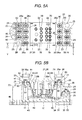
Fig. 5A is a plan view of the relay socket illustrated inFig. 1B ; -
Fig. 5B is a section view taken along line V-V inFig. 5A ; -
Fig. 6 is a perspective view of a partially enlarged section of the relay illustrated inFigs. 1A and 1B ; -
Fig. 7 is a perspective view of the partially enlarged section seen from a different angle from that inFig. 6 ; -
Fig. 8 is a perspective view of partially enlarged components for illustrating an assembling method; -
Fig. 9A is an exploded perspective view of enlarged main components in a second embodiment; -
Fig. 9B is an exploded perspective view of enlarged main components in a third embodiment; -
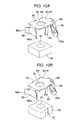
Fig. 10A is an exploded perspective view of enlarged main components in a fourth embodiment; -
Fig. 10B is an exploded perspective view of enlarged main components in a fifth embodiment; -
Fig. 11A is a perspective view of enlarged main components in a sixth embodiment; -
Fig. 11B is an exploded perspective view of the enlarged main components in the sixth embodiment; -
Fig. 12 is a perspective view of a partially enlarged section in a seventh embodiment; -
Fig. 13 is a perspective view of the partially enlarged section in the seventh embodiment, the partially enlarged section seen from a different angle from that inFig. 12 ; -
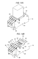
Fig. 14A is a perspective view of a second application example in which the lead wire connection structure is applied to a relay socket, and illustrates a state that a relay is attached to the relay socket; -
Fig. 14B is a perspective view of the second application example, and illustrates a state that the relay is detached from the relay socket; -
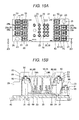
Fig. 15A is a plan view of the relay socket illustrated inFig. 14B ; -
Fig. 15B is a section view taken along line XV-XV inFig. 15A ; -
Fig. 16A is a perspective view of a third application example in which the lead wire connection structure is applied to a relay socket, and illustrates a state that a relay is attached to the relay socket; -
Fig. 16B is a perspective view of the third application example, and illustrates a state that the relay is detached from the relay socket; -
Fig. 17A is a plan view of the relay socket illustrated inFig. 16B ; -
Fig. 17B is a section view taken along line XVII-XVII inFig. 17A ; -
Fig. 18 is an exploded perspective view of the relay socket illustrated inFig. 16B ; -
Fig. 19 is an exploded perspective view of the relay socket illustrated inFig. 16B , the relay socket seen from a different angle from that inFig. 18 ; -
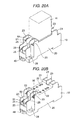
Fig. 20A is a perspective view of a fourth application example in which the lead wire connection structure is applied to a relay socket, and illustrates a state that a relay is attached to the relay socket; -
Fig. 20B is a perspective view of the fourth application example, and illustrates a state that the relay is detached from the relay socket; -
Fig. 21A is a plan view of the relay socket illustrated inFig. 20B ; and -
Fig. 21B is a section view taken along line XXI-XXI inFig. 21A . - Description will be given of embodiments in which a lead wire connection structure according to the disclosure is applied to a
relay socket 10 as illustrated inFigs. 1A to 21B attached herein. - In the first embodiment, as illustrated in
Figs. 1A and 1B , therelay socket 10 has a configuration that arelay 11 is attachable thereto. Moreover, as illustrated inFigs. 2 and3 , therelay socket 10 includes acover 20, abase 30, and a plurality oflead wires 60 housed and wired in a space formed by thecover 20 and thebase 30. - As illustrated in
Fig. 2 , thecover 20 is formed into a substantially box shape, and has apositioning recess 21 formed on a center of a top surface thereof. Thepositioning recess 21 has a plurality of insertion holes 22 formed in a bottom surface thereof and arranged in a lattice form. Each of the insertion holes 22 is formed into a substantially cross shape as seen in a planar view, and has a structure that a contact 70 (which will be described later) can be inserted from below. - The
cover 20 has a plurality of front-to-rear two-level insulation walls 23 formed on opposite side surfaces thereof with a predetermined pitch, and also has arearward partition wall 24 and aforward partition wall 25 integrally formed in parallel with each other between theinsulation walls 23 and 23 (seeFig. 6 ). Thus, a terminal 80 and a nut 90 (each of which will be described later) can be housed in a space formed by theinsulation walls rearward partition wall 24 and theforward partition wall 25. Therearward partition wall 24 has anotch 24a formed on a lower end edge thereof, and theforward partition wall 25 haspositioning projections forward partition wall 25 has a substantially E shape as seen in a planar view (seeFig. 6 ). Theinsulation walls finger protector 26 integrally formed on upper ends thereof, and thefinger protector 26 has awork hole 26a which facilitates connecting work and improves safety. Thecover 20 has an opening, and engagement latches 27 formed on inner edges of the opening so as to be engaged with the base 30 as will be described later (seeFig. 3 ). Thecover 20 also hasscrew fixing holes 28 formed in diagonally opposite corners thereof such that thecover 20 is fastened to a different device with screws. - As illustrated in
Fig. 2 , thebase 30 is formed into such a planar shape as to close the opening of thecover 20, and has a plurality ofsupport plates 31 formed in parallel with one another with a predetermined pitch on a top surface thereof so as to protrude from the top surface. Thesupport plates 31 are inserted along opposite surfaces of theinsulation walls cover 20, and are brought into contact with both lower edges of thenut 90 as will be described later, thereby positioning thenut 90. As illustrated inFig. 3 , thebase 30 also has a pair oflatch receivers 32 formed on opposite front and rear surfaces thereof, respectively, such that the engagement latches 27 of thecover 20 can be engaged with thelatch receivers 32. The base 30 also has agroove 33 formed on a center of a bottom surface thereof. Thegroove 33 is formed for slidably attaching a guide rail (not illustrated) formed into a hat shape as seen in a sectional view. The base 30 also has a pair of engagement latches 34 formed on one side edge of thegroove 33, and a mountinggroove 35 formed on the other side edge of thegroove 33. The mountinggroove 35 is formed for attaching a rail guide member 40 (which will be described later), and is orthogonal to thegroove 33. The mountinggroove 35 has alocking hole 35a formed in a ceiling surface thereof. - As illustrated in
Fig. 3 , therail guide member 40 is formed into such a frame shape as to be slidably attached to the mountinggroove 35 formed on the bottom surface of thebase 30, and has an S-shapedspring 41 integrally formed thereinside. When therail guide member 40 is laterally attached to the mountinggroove 35, a locking projection 42 (seeFig. 2 ) formed on the S-shapedspring 41 is locked by the lockinghole 35a formed in the bottom surface of thebase 30. Thus, therail guide member 40 is prevented from being detached from thebase 30. More specifically, the pair of engagement latches 34 formed on the bottom surface of thebase 30 is engaged with one side edge of the guide rail (not illustrated) formed into a hat shape as seen in a sectional shape, and atip end latch 43 of therail guide member 40 is engaged with the other side edge of the guide rail. Thus, thebase 30 is slidably attached to the guide rail. - As illustrated in
Figs. 4A and 4B , each of thelead wires 60 is easily bent, and has first and second ends 61 and 62. Thecontact 70 is secured by crimping to and electrically connected to a core wire at thefirst end 61, and the terminal 80 for holding thenut 90 is secured by crimping to and electrically connected to a core wire at thesecond end 62. If necessary, thecontact 70 and the terminal 80 may be electrically connected by soldering to the core wires, respectively. - The
contact 70 has the following structure. That is, a terminal (not illustrated) of therelay 11 is press fitted into between a pair ofelastic contact pieces 71 and 72 each of which is formed in such a manner that an electrically conductive metal plate is stamped out by press working and then the stamped plate is bent. Thus, thecontact 70 can be electrically connected to therelay 11. Each of theelastic contact pieces 71 and 72 has aguide tongue piece 73 which is formed by bending and raising a tip end of each elastic contact piece outward. Therefore, even in the state that thecontact 70 is housed in theinsertion hole 22 of thecover 20, the terminal of therelay 11 can be easily press fitted into thecontact 70 through theguide tongue pieces contact 70 is electrically connected to thefirst end 61 of thelead wire 60 in such a manner that a crimpinglatch 74 extending from theelastic contact piece 71 is crimped inward. - The terminal 80 is formed in such a manner that an electrically conductive metal plate is stamped out by press working, as in the
contact 70. More specifically, the terminal 80 has a terminalmain body 81 formed into a quadrilateral shape as seen in a planar view, a throughhole 82 formed in the terminalmain body 81, and a pair of elastic holdingparts 83 extending from centers of both opposite side edges of the terminalmain body 81. Theelastic holding parts 83 are bent twice to hold thenut 90 as will be described later. In order to prevent misalignment of the temporarily heldnut 90, the terminal 80 also haspositioning tongue pieces 84 formed to extend from the side edges of the terminalmain body 81 and bent at an obtuse angle. - The terminal 80 also has a
connection part 85 extending from one of sides thereof other than the sides where elastic holdingparts 83 are formed, and an elasticpress tongue piece 86 extending from the remaining side thereof. The elasticpress tongue piece 86 is formed into a substantially T shape. Theconnection part 85 is formed of a thin metal plate, and therefore is easily bent. Particularly, theconnection part 85 is bent at an obtuse angle with respect to the terminalmain body 81, so that a space for housing the terminal 80 is reduced. Moreover, theconnection part 85 has two sets of crimpinglatches 85a protruding from both side edges thereof. When the crimpinglatches 85a are crimped inward, the terminal 80 is electrically connected to thesecond end 62 of thelead wire 60. On the other hand, the elasticpress tongue piece 86 is bent at a substantially right angle with respect to the terminalmain body 81, and both side edges of the elasticpress tongue piece 86 are bent and raised. Thus, lockinglatches 86a are formed. - The
nut 90 is substantially equal in planar shape to the terminalmain body 81, and is slightly smaller in size than the terminalmain body 81. Moreover, thenut 90 has aninternal thread hole 91 formed in a center thereof. Thenut 90 is press fitted into between the elastic holdingparts lead wire 60. Thus, thenut 90 is held by the terminal 80. Herein, the shapes of the terminalmain body 81, throughhole 82 and elastic holdingparts hole 82 of the terminalmain body 81 and theinternal thread hole 91 of thenut 90 can be coaxially arranged. Since the terminalmain body 81 and thenut 90 are substantially equal in planar shape to each other, thenut 90 supports the entire bottom surface of the terminalmain body 81 even when the terminalmain body 81 of the terminal 80 is formed of a thin metal plate. Therefore, even when a screw 50 (which will be described later) is screwed into theinternal thread hole 91 of thenut 90, the terminalmain body 81 can be prevented from being plastically deformed and predetermined tightening torque can be ensured. - Moreover, the
positioning tongue pieces 84 are brought into contact with opposite outer side corners of thenut 90, so that the temporarily heldnut 90 can be prevented from being misaligned. - Herein, the shape of the
nut 90 is not limited to a quadrilateral shape as seen in a planar shape, but may be, for example, a right hexagonal shape as seen in a planar view. - Next, description will be given of a method for assembling the constituent components described above.
- First, the
contact 70 and the terminal 80 are connected by crimping to thefirst end 61 and thesecond end 62 of thelead wire 60, respectively, and thenut 90 is held by the elastic holdingparts rail guide member 40 is slid into and engaged with the mountinggroove 35 of thebase 30. Moreover, the lockingprojection 42 of therail guide member 40 is locked by the lockinghole 35a of the base 30 such that therail guide member 40 is prevented from being detached from thebase 30. - On the other hand, the
cover 20 is positioned with the opening thereof directed upward. Then, theinverted screw 50 having awasher 51 attached thereto is inserted into the space formed by theinsulation walls rearward partition wall 24 and theforward partition wall 25. Herein, a head of thescrew 50 is fitted into thework hole 26a of thefinger protector 26, and thewasher 51 is locked by an opening edge of thework hole 26a, so that thescrew 50 is positioned. Therefore, the assembling work is facilitated. - As illustrated in
Fig. 8 , next, the terminal 80 and thenut 90 each connected to thelead wire 60 are temporarily fixed in the space formed by theinsulation walls rearward partition wall 24 and theforward partition wall 25. Thus, theconnection part 85 of the terminal 80 is engaged with thenotch 24a of therearward partition wall 24, and the inward surface of thenut 90 is brought into contact with therearward partition wall 24, so that thenut 90 is positioned. On the other hand, both side surfaces of thenut 90 are positioned by theinsulation walls parts 83 and thepositioning tongue pieces 84. Moreover, a center of the elasticpress tongue piece 86 of the terminal 80 is positioned by thepositioning projection 25a of theforward partition wall 25, and an outward surface of thenut 90 is positioned by thepositioning projection 25b of theforward partition wall 25. Herein, the locking latches 86a formed on both ends of the elasticpress tongue piece 86 are locked by thepositioning projections nut 90 are prevented from dropping off. Further, a tip end of a shank of thescrew 50 is fitted into theinternal thread hole 91 of thenut 90. Therefore, thescrew 50 can be prevented from dropping off and the assembling work is facilitated. - As illustrated in
Fig. 5B , moreover, since theconnection part 85 of the terminal 80 is bent at an obtuse angle with respect to the terminalmain body 81, the space for housing the terminal 80 in thecover 20 can be minimized. Further, aninternal partition wall 24b extends from the ceiling surface of thecover 20 at the rear side of theconnection part 85. Theinternal partition wall 24b can ensure a high insulating property between the terminal 80 and thecontact 70. - Then, the
base 30 is fitted into the opening of thecover 20, and theengagement latch 27 of thecover 20 is engaged with thelatch receiver 32 of the base 30 such that thecover 20 and the base 30 are prevented from being separated from each other. Thus, the terminal 80 and thenut 90 each of which is connected to thelead wire 60 are housed and disposed in the space formed by thecover 20 and thebase 30. Moreover, both lower side edges of thenut 90 are pressed against the upper ends of the pair ofsupport plates 31 of thebase 30. Therefore, theconnection part 85 of the terminal 80 is engaged with thenotch 24a of therearward partition wall 24 such that the terminal 80 is prevented from being detached from the cover 20 (seeFig. 6 ). Further, the lockinglatch 86a of the elasticpress tongue piece 86 is locked by thepositioning projection 25b of theforward partition wall 25 such that the terminal 80 is prevented from being detached from the cover 20 (seeFig. 7 ). That is, the terminal 80 and thenut 90 are held from above by thenotch 24a of therearward partition wall 24 and thepositioning projections 25b of theforward partition wall 25 in thecover 20, and are also held from below by thesupport plates 31 protruding from the top surface of thebase 30. - As illustrated in
Fig. 8 , particularly, thepositioning tongue piece 84 of the terminal 80 is elastically deformed to come into press contact with the opposite surfaces of theinsulation walls cover 20, thus, thenut 90 is supported with the elastic holdingparts positioning tongue pieces nut 90 can be supported without wobbling. - In the first embodiment, the elastic holding
parts positioning tongue pieces nut 90, and are also acted for supporting thecover 20 and thenut 90. Alternatively, the elastic holdingparts nut 90, and thepositioning tongue pieces cover 20. - Next, the
screw 50 is screwed into theinternal thread hole 91 of thenut 90 through thework hole 26a of thecover 20. Thus, the assembling work is finished. - According to the first embodiment, since the
lead wire 60 is easily bent, the assembling work is facilitated. - According to the first embodiment, moreover, the elastic holding
parts 83 of the terminal 80 hold thenut 90 such that thenut 90 is prevented from dropping off. Therefore, the assembling work is further facilitated. - According to the first embodiment, further, the
screw 50 can be accurately set at a predetermined position in such a manner that the head of thescrew 50 is fitted into thework hole 26a of thefinger protector 26. Therefore, the assembling work for the terminal 80 and thenut 90 is facilitated. - When the terminal 80 and the
nut 90 are positioned in thecover 20, the tip end of the shank of thescrew 50 is fitted into theinternal thread hole 91 of thenut 90, so that thescrew 50 can be prevented from dropping off. Therefore, the assembling work is further facilitated. - As illustrated in
Fig. 9A , the second embodiment is almost equal to the first embodiment, but is different from the first embodiment in the following point. That is,engagement grooves 92 are formed on opposite outer side surfaces of thenut 90, and the terminal 80 holds thenut 90 in such a manner that the elastic holdingparts 83 are engaged with theengagement grooves 92. For convenience of the description, the same constituent components are denoted with the same reference signs, and the detailed description thereof will not be given here. - According to the second embodiment, the elastic holding
parts 83 are engaged with theengagement grooves 92. Therefore, thenut 90 can be accurately held and is less prone to drop off. - As illustrated in
Fig. 9B , the third embodiment is almost equal to the first embodiment, but is different from the first embodiment in the following point. That is,engagement grooves 92 are formed on opposite outer side surfaces of thenut 90 so as to cut through the outer side surfaces, and the terminal 80 holds thenut 90 in such a manner that the elastic holdingparts 83 are engaged with theengagement grooves 92. For convenience of the description, the same constituent components are denoted with the same reference signs, and the detailed description thereof will not be given here. - According to the third embodiment, the
nut 90 can be accurately held and is less prone to drop off. Moreover, thenut 90 is easily manufactured. - As illustrated in
Fig. 10A , the fourth embodiment is almost equal to the first embodiment, but is different from the first embodiment in the following point. That is, the terminal 80 holds thenut 90 so as to pinch the entire side surfaces of thenut 90 with the elastic holdingparts 83. For convenience of the description, the same constituent components are denoted with the same reference signs, and the detailed description thereof will not be given here. - According to the fourth embodiment, the
nut 90 is pinched by the elastic holdingparts 83, and therefore is still less prone to drop off. - As illustrated in
Fig. 10B , the fifth embodiment is almost equal to the first embodiment, but is different from the first embodiment in the following point. That is,engagement grooves 92 are formed on opposite outer side surfaces of thenut 90 so as to cut through the outer side surfaces, and the elastic holdingparts 83 of the terminal 80 are engaged with theengagement grooves 92 to pinch thenut 90. For convenience of the description, the same constituent components are denoted with the same reference signs, and the detailed description thereof will not be given here. - According to the fifth embodiment, the
nut 90 can be more accurately and firmly held, and therefore is still less prone to drop off. - As illustrated in
Figs. 11A and 11B , the sixth embodiment is almost equal to the first embodiment, but is different from the first embodiment in the following point. That is, chamferedportions 90a are formed on edges of the top surface of thenut 90. Moreover, an annular chamferedportion 91 a is formed on an opening edge of theinternal thread hole 91 of thenut 90. On the other hand, a throughhole 82 is formed in the terminal 80 so as to be larger in diameter than the opening edge of theinternal thread hole 91 of thenut 90. - According to the sixth embodiment, the
chamfered portions 90a allow the elastic holdingparts 83 of the terminal 80 to be easily attached to thenut 90. Unlike the foregoing embodiments, therefore, the elastic holdingparts 83 are not necessarily bent twice, but are merely bent once. That is, productivity is improved. - Moreover, the proximal end of the elastic holding
part 83 and the proximal end of thepositioning tongue piece 84 do not interfere with the outer peripheral edge of thenut 90. Therefore, the elastic holdingpart 83 and thepositioning tongue piece 84 are easily bent. That is, the productivity is further improved. - Further, even when the
screw 50 is misaligned, the annular chamferedportion 91 a guides thescrew 50 to theinternal thread hole 91. Therefore, thescrew 50 can be screwed into theinternal thread hole 91 with certainty. - Herein, each of the chamfered
portion 90a and the annular chamferedportion 91 a is not limited to a C-plane, but may be an R-plane. - Moreover, the
chamfered portions 90a and the annular chamferedportion 91 a may be symmetrically formed on the top and bottom surfaces of thenut 90. When thechamfered portions 90a and the annular chamferedportion 91 a are formed on the top and bottom surfaces of thenut 90 as described above, thenut 90 is easily aligned in the assembling work. Therefore, assembling workability is improved. - As illustrated in
Figs. 12 and13 , the seventh embodiment is almost equal to the first embodiment, but is different from the first embodiment in the following point. That is, apositioning projection 31 a is formed on the upper end of thesupport plate 31 of the base 30 to position the inward surface of thenut 90. For convenience of the description, the same constituent components are denoted with the same reference signs, and the detailed description thereof will not be given here. - According to the seventh embodiment, since the
nut 90 can be positioned by thepositioning projection 31 a of thesupport plate 31, a tolerance upon incorporating the terminal 80 and thenut 90 in thecover 20 becomes large. Therefore, therelay socket 10 is obtained with improved assembling workability. - The
relay socket 10 to be employed in the disclosure is not limited to the 14-pin relay socket 10 provided with thefinger protector 26 having thework hole 26a in the first embodiment. As illustrated inFigs. 14A to 15B , for example, the lead wire connection structure may be applied to a 14-pin relay socket 10 provided with no finger protector (a second application example). - Moreover, the
relay socket 10 to be employed in the disclosure is not limited to the 14-pin relay socket 10 provided with thefinger protector 26 having thework hole 26a in the first embodiment. As illustrated inFigs. 16A to 19 , the lead wire connection structure may be applied to an 8-pin relay socket 10 provided with a finger protector 26 (a third application example). - As illustrated in
Figs. 20A to 21B , further, the lead wire connection structure may be applied to an 8-pin relay socket 10 provided with no finger protector (a fourth application example). - In the respective application examples described above, for convenience of the description, the same constituent components are denoted with the same reference signs, and the detailed description thereof will not be given here.
- In the foregoing embodiments, the lead wire connection structure is applied to the relay socket; however, the disclosure is not limited to the relay socket. For example, the lead wire connection structure may be applied to a different electronic device.
Claims (11)
- A lead wire connection structure comprising:a terminal including
a terminal main body having a through hole, and
a connection part extending from one end of the terminal main body; anda lead wire having one end connected to the connection part,whereina pair of elastic holding parts extending from both opposite side edges of the terminal main body holds both side surfaces of a nut, andan internal thread hole of the nut and the through hole are coaxially arranged. - The lead wire connection structure according to claim 1, wherein
the nut is formed into a quadrilateral shape as seen in a planar view. - The lead wire connection structure according to claim 2, wherein
the connection part is bent with respect to the terminal main body. - The lead wire connection structure according to any one of claims 1 to 3, wherein
the nut has engagement grooves formed on opposite side surfaces thereof, and
the elastic holding parts of the terminal are engaged with the engagement grooves. - The lead wire connection structure according to claim 4, wherein
the engagement grooves are formed to cut through the side surfaces of the nut. - The lead wire connection structure according to any one of claims 1 to 5, wherein
the elastic holding parts pinch the side surfaces of the nut to hold the nut. - The lead wire connection structure according to any one of claims 1 to 6, wherein
the nut has chamfered portions formed on at least a pair of edges of the opposite side surfaces thereof, the edges being opposite to each other with the internal thread hole interposed therebetween. - The lead wire connection structure according to any one of claims 1 to 7, wherein
the nut has an annular chamfered portion formed along an opening edge of the internal thread hole thereof, and
the terminal main body has a through hole having a diameter which is equal to or more than an outer peripheral diameter of the annular chamfered portion. - The lead wire connection structure according to any one of claims 1 to 8, wherein
the chamfered portions and the annular chamfered portion are symmetrically formed on top and bottom surfaces of the nut. - An electronic device comprising:a cover;a base; andthe lead wire connection structure according to any one of claims 1 to 9, whereinthe lead wire connection structure is housed and disposed in a space formed by the cover and the base.
- The electronic device according to claim 10, wherein
the terminal and the nut are held by an inner surface of the cover and a support plate protruding from a top surface of the base.
Applications Claiming Priority (1)
| Application Number | Priority Date | Filing Date | Title |
|---|---|---|---|
| JP2013201848A JP2015069772A (en) | 2013-09-27 | 2013-09-27 | Lead wire connection structure and electronic device using the same |
Publications (1)
| Publication Number | Publication Date |
|---|---|
| EP2854225A1 true EP2854225A1 (en) | 2015-04-01 |
Family
ID=51265623
Family Applications (1)
| Application Number | Title | Priority Date | Filing Date |
|---|---|---|---|
| EP14180039.1A Withdrawn EP2854225A1 (en) | 2013-09-27 | 2014-08-06 | Lead wire connection structure and electronic device including the same |
Country Status (4)
| Country | Link |
|---|---|
| US (1) | US20150093930A1 (en) |
| EP (1) | EP2854225A1 (en) |
| JP (1) | JP2015069772A (en) |
| CN (2) | CN204167536U (en) |
Families Citing this family (9)
| Publication number | Priority date | Publication date | Assignee | Title |
|---|---|---|---|---|
| JP2015069772A (en) * | 2013-09-27 | 2015-04-13 | オムロン株式会社 | Lead wire connection structure and electronic device using the same |
| DE102015107188A1 (en) * | 2015-05-08 | 2016-11-10 | Semikron Elektronik Gmbh & Co. Kg | Power electronics unit |
| CN105023812A (en) * | 2015-07-13 | 2015-11-04 | 国家电网公司 | Unilateral residual current operated circuit breaker installation base |
| JP1558909S (en) * | 2016-02-29 | 2016-09-20 | ||
| JP6612207B2 (en) * | 2016-12-19 | 2019-11-27 | 矢崎総業株式会社 | Conductor module |
| CN110224234B (en) * | 2018-03-02 | 2024-03-22 | 日本电产三协电子(东莞)有限公司 | Driving device |
| CN110310865B (en) * | 2019-07-22 | 2024-02-20 | 三友联众集团股份有限公司 | Contact conduction structure for relay |
| DE102020204129B3 (en) * | 2020-03-30 | 2021-05-12 | Volkswagen Aktiengesellschaft | Cable lug for attachment to a connecting element |
| JP2023176298A (en) | 2022-05-31 | 2023-12-13 | 富士電機株式会社 | Terminal structure, method for manufacturing terminal structure, and semiconductor device |
Citations (6)
| Publication number | Priority date | Publication date | Assignee | Title |
|---|---|---|---|---|
| FR1390790A (en) * | 1964-04-17 | 1965-02-26 | Bishop & Babcock Corp | Set, to be fixed in the opening of a panel, comprising a cage and a nut |
| FR2036106A5 (en) * | 1969-03-04 | 1970-12-24 | Dauphinoise La | |
| JP2000100540A (en) | 1998-09-22 | 2000-04-07 | Idec Izumi Corp | Electric component with lead wire and conductive metal fitting and its manufacture |
| EP1017130A2 (en) * | 1998-12-29 | 2000-07-05 | Eaton Corporation | Self-retaining spring clip assembly and an electrical connection incorporating the same |
| EP1133007A1 (en) * | 2000-03-09 | 2001-09-12 | Sumitomo Wiring Systems, Ltd. | A construction and a terminal cap for preventing an erroneous connection |
| US20030186121A1 (en) * | 2002-03-27 | 2003-10-02 | Csb Battery Co., Ltd. | Terminal having nut-positioning device |
Family Cites Families (10)
| Publication number | Priority date | Publication date | Assignee | Title |
|---|---|---|---|---|
| JPS5012674Y1 (en) * | 1969-08-08 | 1975-04-18 | ||
| JPS6046669U (en) * | 1983-09-06 | 1985-04-02 | 株式会社 エルコ.インタ−ナシヨナル | Power supply terminal block |
| JPS62113368A (en) * | 1985-11-12 | 1987-05-25 | 神保電器株式会社 | Terminal structure |
| JPH0345435Y2 (en) * | 1986-01-10 | 1991-09-25 | ||
| JPS6350463U (en) * | 1986-09-19 | 1988-04-05 | ||
| JP2000058151A (en) * | 1998-08-04 | 2000-02-25 | Funai Electric Co Ltd | Connection terminal for electronic equipment |
| JP4129833B2 (en) * | 2002-12-26 | 2008-08-06 | フジコン株式会社 | PCB terminal hardware |
| CN202068165U (en) * | 2011-01-25 | 2011-12-07 | 乐清市凯昆贸易有限公司 | Cable tapered end device |
| CN102354834B (en) * | 2011-08-25 | 2013-08-21 | 东莞市维峰五金电子有限公司 | A method of manufacturing a connection terminal |
| JP2015069772A (en) * | 2013-09-27 | 2015-04-13 | オムロン株式会社 | Lead wire connection structure and electronic device using the same |
-
2013
- 2013-09-27 JP JP2013201848A patent/JP2015069772A/en active Pending
-
2014
- 2014-08-06 EP EP14180039.1A patent/EP2854225A1/en not_active Withdrawn
- 2014-08-27 US US14/470,576 patent/US20150093930A1/en not_active Abandoned
- 2014-08-29 CN CN201420495654.1U patent/CN204167536U/en not_active Expired - Lifetime
- 2014-08-29 CN CN201410436568.8A patent/CN104518307A/en active Pending
Patent Citations (6)
| Publication number | Priority date | Publication date | Assignee | Title |
|---|---|---|---|---|
| FR1390790A (en) * | 1964-04-17 | 1965-02-26 | Bishop & Babcock Corp | Set, to be fixed in the opening of a panel, comprising a cage and a nut |
| FR2036106A5 (en) * | 1969-03-04 | 1970-12-24 | Dauphinoise La | |
| JP2000100540A (en) | 1998-09-22 | 2000-04-07 | Idec Izumi Corp | Electric component with lead wire and conductive metal fitting and its manufacture |
| EP1017130A2 (en) * | 1998-12-29 | 2000-07-05 | Eaton Corporation | Self-retaining spring clip assembly and an electrical connection incorporating the same |
| EP1133007A1 (en) * | 2000-03-09 | 2001-09-12 | Sumitomo Wiring Systems, Ltd. | A construction and a terminal cap for preventing an erroneous connection |
| US20030186121A1 (en) * | 2002-03-27 | 2003-10-02 | Csb Battery Co., Ltd. | Terminal having nut-positioning device |
Also Published As
| Publication number | Publication date |
|---|---|
| JP2015069772A (en) | 2015-04-13 |
| CN104518307A (en) | 2015-04-15 |
| CN204167536U (en) | 2015-02-18 |
| US20150093930A1 (en) | 2015-04-02 |
Similar Documents
| Publication | Publication Date | Title |
|---|---|---|
| EP2854225A1 (en) | Lead wire connection structure and electronic device including the same | |
| EP3361575B1 (en) | Connector | |
| US8834194B2 (en) | LED socket having a housing with a securing member and a LED module receiving portion | |
| US9525218B2 (en) | Conductive wire connection structure of rail-type electrical terminal | |
| CN103840319B (en) | Ground terminal and the connector using the ground terminal | |
| US9496108B2 (en) | Electronic component, connection structure of electronic component and terminal fitting, and electrical junction box having electronic component | |
| JP5672348B1 (en) | Wiring module | |
| JP6555028B2 (en) | Cable crimp terminal assembly | |
| JP2007043484A (en) | Speaker apparatus, manufacturing method of speaker apparatus, and frame for speaker apparatus | |
| US10587057B2 (en) | Terminal, and electrical connector | |
| EP2549593A2 (en) | Screw terminal block, electric motor controller, and electrical device | |
| JP2012109039A (en) | Terminal connection structure | |
| US20180013225A1 (en) | Connection Terminal and Electrical Connector | |
| US10374339B2 (en) | Battery terminal | |
| JP2012230770A (en) | Electric connection device for led lighting and harness | |
| US9698504B2 (en) | Battery terminal | |
| US9461372B2 (en) | Female terminal fitting | |
| JPWO2015029990A1 (en) | Connection structure between electronic parts and terminal fittings | |
| KR101653062B1 (en) | Electrical connector | |
| JP6681655B2 (en) | Coaxial connector | |
| JP5911305B2 (en) | Connector device | |
| JP2015084311A (en) | Female terminal with outer | |
| JP4880640B2 (en) | socket | |
| JP2024175894A (en) | Wiring connection device | |
| JP2010287480A (en) | Electrical connector and LED module assembly using the same |
Legal Events
| Date | Code | Title | Description |
|---|---|---|---|
| PUAI | Public reference made under article 153(3) epc to a published international application that has entered the european phase |
Free format text: ORIGINAL CODE: 0009012 |
|
| 17P | Request for examination filed |
Effective date: 20140806 |
|
| AK | Designated contracting states |
Kind code of ref document: A1 Designated state(s): AL AT BE BG CH CY CZ DE DK EE ES FI FR GB GR HR HU IE IS IT LI LT LU LV MC MK MT NL NO PL PT RO RS SE SI SK SM TR |
|
| AX | Request for extension of the european patent |
Extension state: BA ME |
|
| R17P | Request for examination filed (corrected) |
Effective date: 20150929 |
|
| RBV | Designated contracting states (corrected) |
Designated state(s): AL AT BE BG CH CY CZ DE DK EE ES FI FR GB GR HR HU IE IS IT LI LT LU LV MC MK MT NL NO PL PT RO RS SE SI SK SM TR |
|
| STAA | Information on the status of an ep patent application or granted ep patent |
Free format text: STATUS: EXAMINATION IS IN PROGRESS |
|
| 17Q | First examination report despatched |
Effective date: 20170927 |
|
| STAA | Information on the status of an ep patent application or granted ep patent |
Free format text: STATUS: THE APPLICATION IS DEEMED TO BE WITHDRAWN |
|
| 18D | Application deemed to be withdrawn |
Effective date: 20180208 |