EP2854051A2 - Simulation device, simulation program, and simulation method - Google Patents
Simulation device, simulation program, and simulation method Download PDFInfo
- Publication number
- EP2854051A2 EP2854051A2 EP20140179655 EP14179655A EP2854051A2 EP 2854051 A2 EP2854051 A2 EP 2854051A2 EP 20140179655 EP20140179655 EP 20140179655 EP 14179655 A EP14179655 A EP 14179655A EP 2854051 A2 EP2854051 A2 EP 2854051A2
- Authority
- EP
- European Patent Office
- Prior art keywords
- particle
- interaction
- neighboring
- calculating
- displacement
- Prior art date
- Legal status (The legal status is an assumption and is not a legal conclusion. Google has not performed a legal analysis and makes no representation as to the accuracy of the status listed.)
- Withdrawn
Links
Images


Classifications
-
- G—PHYSICS
- G06—COMPUTING; CALCULATING OR COUNTING
- G06F—ELECTRIC DIGITAL DATA PROCESSING
- G06F30/00—Computer-aided design [CAD]
- G06F30/20—Design optimisation, verification or simulation
-
- G—PHYSICS
- G06—COMPUTING; CALCULATING OR COUNTING
- G06F—ELECTRIC DIGITAL DATA PROCESSING
- G06F2111/00—Details relating to CAD techniques
- G06F2111/10—Numerical modelling
Definitions
- the embodiments discussed herein are related to a simulation device, simulation program, and simulation method.
- a fluid for which calculations are performed is represented as a collection of particles, and special treatment does not need to be prepared to deal with a moving boundary.
- the particle methods have been widely used in recent years.
- a particle located within a radius of influence (kernel radius) of a certain particle i.e., located within a distance h from the certain particle, is defined as a neighboring particle and information thereon is used.
- formula 1 expresses discretization of an equation of motion in the SPH method.
- D ⁇ v a dt - ⁇ b m b P b + P a ⁇ b ⁇ ⁇ a + ⁇ ab ⁇ ⁇ W ⁇ r a - r b h ⁇ r a
- a subscript a indicates a certain particle
- a subscript b indicates a neighboring particle
- r a , v a , ⁇ a , P a , and m a respectively indicate the position vector, the rate vector, the density, the pressure, and the mass of the particle a.
- W a kernel function
- a function such as the following cubic spline function, formula 2
- W r h ⁇ 1 - 1.5 ⁇ r h 2 + 0.75 ⁇ r h 3 / ⁇ 0 ⁇ r h ⁇ 1 0.25 ⁇ 2 - r h 3 / ⁇ 1 ⁇ r h ⁇ 2 0 2 ⁇ r h
- an acceleration is calculated by discretizing a deformation gradient tensor expressed by the following formula, formula 3.
- F ij ⁇ u i ⁇ X j + I
- X j indicate a j component of the distance between positions; u i , an i component of displacement; I, an identity tensor.
- the deformation gradient tensor of a certain particle a may be expressed by the following formula, formula 4, by superimposing the influence of a neighboring particle b.
- F ij a - ⁇ i m b ⁇ b du i a - du i b ⁇ ⁇ W r h ⁇ x j b + I
- non-patent document 1 a technique is known wherein, in the analyzing of an element such as an elastic body, even after the initial calculation for a neighboring particle progresses and a particle position changes, that particle continues to be dealt with as a neighbor.
- Patent document 1 discloses a technology for identifying a particle that interacts with other particles.
- Patent document 2 discloses the following technology. To search for a particle that is a neighbor of certain distributed particles, the distances from all of the other particles would need to be determined, and a determination would need to be repeatedly made on whether a particle is a neighbor. However, particles distributed within a space are divided into two kinds : particles for which new attribute information is calculated by searching a neighboring particle; and particles for which new attribute information is calculated from attribute information thereof without searching a neighboring particle. Calculating processes corresponding to the two kinds of particles are performed, thereby decreasing the number of times a search of a neighboring particle is performed.
- Patent document 3 discloses a technology wherein, in a functional calculus of a force or potential that corresponds to the distance between particles, a differential coefficient of a function is used to determine a new potential using an interpolation method.
- a value determined according to a distance for an initial position is identical with a value after deformation, but the derivative is not identical with the one for the initial position.
- a calculation needs to be performed after the initial position is converted into the reference position. Accordingly, a stress needs to be calculated as, for example, a Piola-Kirchhoff stress, namely, a stress value for the reference position.
- an object of the present invention is to provide a simulation device, a simulation program, and a simulation method to allow calculations to be readily performed in consideration of stress values that work in the coordinates after deformation of an elastic body.
- the invention uses the following configuration.
- one aspect of the invention provides a simulation program that causes a computer to: for each of one or more first neighboring particles located within a radius of influence of a reference particle of a continuum model expressing a continuum as a collection of particles, calculate a first interaction between the reference particle and the first neighboring particle according to a kernel function and the position of the first neighboring particle after displacement of the continuum model; for each of one or more second neighboring particles that have entered the radius of influence of the reference particle after the displacement occurred, calculate a second interaction between the reference particle and the second neighboring particle according to the kernel function and the position of the second neighboring particle after displacement of the continuum model; and calculate an interaction between the reference particle and a current neighboring particle of the reference particle according to the first and second interactions, wherein calculating the first interaction includes using the deformation gradient tensor of the kernel function.
- the invention relates to a simulation device, a simulation program executed by a computer, and a simulation method, wherein a continuum that is an object of simulation is considered as a collection of particles.
- the simulation device, the simulation program, and the simulation method of the invention are techniques of treating a neighboring particle in a numerical calculation program that uses a particle method.
- they are techniques of numerically calculating a motion of a continuum such as an elastic body using a particle method; more particularly, they are techniques wherein, in the treating of a neighboring particle, a Cauchy stress after deformation is determined while considering a neighboring particle with reference to a reference position, and a calculation is performed by combining the Cauchy stress with a neighbor after coordinate conversion.
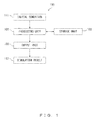
- FIG. 1 illustrates an exemplary configuration of a simulation device to which the invention has been applied.
- a simulation device 100 includes a processing unit 101, a storage unit 102 , and an output unit 103 , and outputs a simulation result 112 after performing a numerical calculation according to an initial condition 111 using a particle method.
- the storage unit 102 stores information on individual calculating formulas for executing a simulation program to which the invention has been applied.
- the processing unit 101 performs a simulation process to which the invention has been applied.
- a first interaction between the reference particle and the first neighboring particle is calculated according to a kernel function and the position of the first neighboring particle after displacement of the continuum model.
- a second interaction between the reference particle and the second neighboring particle is calculated according to the kernel function and the position of the second neighboring particle after displacement of the continuum model.
- an interaction between the reference particle and a current neighboring particle of the reference particle is calculated according to the first and second interactions. Note that the deformation gradient tensor of the kernel function is used to calculate the first interaction.
- the calculating of the interaction between the reference particle and the current neighboring particle in the simulation process allows the first and second interactions to be calculated at an optional ratio.
- the ratio of the calculations of the first and second interactions may be determined in accordance with the degree of displacement of the continuum model.
- the output unit 103 outputs the simulation result 112 of a simulation performed by the processing unit 101.
- a variable with a superscript ini is a value for a reference position
- F a n -1 is a deformation gradient tensor for an (n-1)-th step of a particle a.
- an accurate value of the differentiation of the kernel after deformation of an elastic body may be determined, a Cauchy stress, i.e., a stress within the coordinate system after deformation, can be calculated, and a calculation with another stress within the current coordinate system may be readily performed.
- a deformation gradient tensor may be used in a method for determining the ratio.
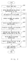
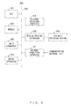
- FIG. 2 is a flowchart illustrating the flow of a simulation process in accordance with a first embodiment.
- step S201 input data is obtained.
- the input data is data to express a continuum particle model that is, for example, a modeled elastic body.
- the input data are, for example, the central coordinates, traveling speeds, radiuses of influence (kernel radiuses), densities, masses, deformation gradient tensors, material property values, and material temperatures of individual particles.
- step S202 according to the central coordinates input in step S201, for each particle, information on a neighboring particle located within a predetermined distance from the particle is obtained and stored in a memory.
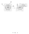
- FIG. 3 illustrates a change in radius of influence that occurs in response to deformation of an elastic body.
- a plurality of neighboring particles 303 are defined within a radius of influence 302 of a reference position that is an arbitrary particle that constitutes the elastic body (hereinafter may be referred to as a "reference particle 301") .
- Deformation of the elastic body results in deformation of the radius of influence 302.
- the radius of influence 302 changes with deformation of the elastic body
- the radius of influence may be supposed to be also extended by N times in that direction.
- the contributions of the volumes of the two particles to each other have the same values as values measured for the reference particle 301. Accordingly, in step S203 in FIG. 2 , without deforming a kernel function under the supposition, the influence after deformation is calculated in accordance with a relative position of the reference particle 301 and the kernel function of the reference particle 301.
- a deformation gradient tensor that uses a differentiation of the kernel function may be calculated without using a position after deformation, and a Cauchy stress may be calculated.
- FIG. 4 illustrates the state of particles indicated when an elastic body is largely deformed.
- FIG. 5 illustrates a concept for use of two kinds of neighbors.
- distal particle 401 a particle initially located at a distant position
- distal particle 401 comes very close to the reference particle 301, or even when these particles become overlapped with each other, these particles may have no influence on each other, and such a phenomenon does not appear to fit in with a real state.
- step S204 using the two kinds of situations , i.e., a situation wherein the reference particle 301 and a neighboring particle 303 are adjacent to each other from the beginning and a situation wherein the reference particle 301 and a distant particle 401 become adjacent to each other after the elastic body is largely deformed, these two kinds are overlapped with each other at a certain ratio.
- the amounts of the two influences are the same.
- the neighboring particle 303 in the process of being deformed may be defined as a reference that has a new influence, and three or more neighboring states may be overlapped with each other. Indicators for overlapping are, for example, the following.
- the influence of the distant particle 401 i.e. , a particle initially located at a distant position
- relative-position coordinates of the particles namely, one indicator for a deformation volume
- P x near /2h (0.5 ⁇ x near /2h ⁇ 1)
- P 0.5 (x near /2h>1)
- step S205 in accordance with a physical model set for an elastic body particle, the motion of the elastic body particle is solved, and a stress is determined.
- C indicates a right Cauchy-Green deformation tensor
- E a Green-Lagrange strain tensor
- Q an elastic potential.
- c 1 and c 2 indicate Mooney-Rivlin parameters
- I c and II c indicate principal invariants of the right Cauchy-Green deformation tensor C.
- step S206 an acceleration is calculated using the Cauchy stress determined in accordance with the formulas up to formula 12.
- D ⁇ v Dt - 1 ⁇ ⁇ ⁇
- ⁇ indicates a Cauchy stress tensor.
- step S207 using a time derivative term that includes the acceleration determined at the end, the physical quantity of the continuum particle is time-integrated, a calculation for one step is completed when the time elapses by a time unit.
- step S208 updated information on the neighboring particles 303 is obtained.
- step S209 a calculation result is output as an external file on an as-needed basis, e.g., when a certain number of steps have elapsed or when a certain simulation time has elapsed.
- step S210 it is determined whether a designated number of steps have been completed; when the designated number of steps have not been completed (step S210: No), step S203 and the following steps are repeated as many times as the designated number of steps, and, then, the simulation process in accordance with the first embodiment is finished.
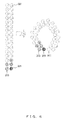
- FIG. 6 illustrates the concept of a situation in which a self-contact calculation is performed.
- the motion of a continuum body particle is solved as described above, and, for a neighboring particle 601 that has become a neighbor after the elastic body is deformed, a repulsive force is determined on the assumption that the reference particle 301 and the neighboring particle 601 have come in contact with each other.
- a repulsive force is determined on the assumption that the reference particle 301 and the neighboring particle 601 have come in contact with each other.
- different influences may be given at a certain ratio, as described above.
- a penalty method or the like may be used to calculate the repulsive force.
- the influences are different factors such as the motion and the contact of the elastic body, and hence the ratio of the influences does not need to be changed.
- FIG. 7 is a flowchart illustrating the flow of a simulation process in accordance with a second embodiment.
- Steps S201-S203 are similar to those in the simulation process of the first embodiment.
- a radius of influence 302 is converted into a radius of influence 302 tailored for the reference coordinates.
- Formula 14 expresses the radius of influence 302, where F indicates a deformation gradient tensor.
- W f r h det ⁇ F ⁇ F - 1 • W r h • F
- W f ( r,h ) indicates a radius of influence specific to a situation in which a reference coordinate system is used.
- step S205 as in the case of the first embodiment, a stress is calculated using both an original neighboring particle 303 and a particle 303 that has become a neighbor after deformation occurred.
- a calculating formula that is essentially the same as that in the first embodiment is used, but a deformation gradient tensor that has not been corrected is used.
- the stress is the one based on the reference coordinate system, which is a first Piola-Kirchhoff stress.
- step S702 using formula 15, a calculation is performed after the stresses are converted into stresses that use the reference coordinate system.
- ⁇ 1 det ⁇ F ⁇ F • ⁇ • F - 1
- Step S206 and the following steps are similar to those in the first embodiment.
- the embodiments of the invention can be widely used for numerical calculations that use a particle method.
- the embodiments can be used to, for example, design a product by analyzing a casting process. Applying any of the embodiments to an elastic body may allow, for example, the shape of sealing gel to be properly determined in the designing of a product.
- the simulation apparatus in FIG. 1 is achievable using, for example, an information processing apparatus (computer) illustrated in FIG. 8 .
- the information processing apparatus in FIG. 8 includes a CPU (Central Processing Unit) 801, a memory 802, an input apparatus 803, an output apparatus 804, an external recording apparatus 805, a medium driving apparatus 806, and a network connecting apparatus 807. These elements are connected to each other by a bus 808.
- CPU Central Processing Unit
- the memory 802 is a semiconductor memory, e.g., a ROM (Read Only Memory), a RAM (Random Access Memory), or a flash memory, and stores a program and data used in the simulation processes.
- the CPU 801 performs the aforementioned simulation processes by executing a program using the memory 802.
- the memory 802 may be used as the storage unit 102 in FIG. 1 .
- the input apparatus 803 is, for example, a keyboard or a pointing device and is used to input information and an instruction from an operator.
- the output apparatus 804 is, for example, a display apparatus, a printer, or a speaker and is used to output a result of processing and to send a query to an operator.
- the output apparatus 804 may be used as the output unit 103 in FIG. 1 .
- the external recording apparatus 805 is, for example, a magnetic disk apparatus, an optical disk apparatus, a magnetic optical disk, or a tape apparatus.
- the external recording apparatus 805 includes a hard disk drive.
- the information processing apparatus may store a program and data in the external recording apparatus 805 and may load them into the memory 802.
- the medium driving apparatus 806 drives a portable recording medium 809 and accesses data recorded therein.
- the portable recording medium 809 is, for example, a memory device, a flexible disk, an optical disk, or a magnetic optical disk.
- the portable recording medium 809 also includes, for example, a Compact Disk Read Only Memory (CD-ROM), a Digital Versatile Disk (DVD), and a Universal Serial Bus (USB) memory.
- CD-ROM Compact Disk Read Only Memory
- DVD Digital Versatile Disk
- USB Universal Serial Bus
- the computer-readable recording media that store a program and data used in the simulation process include physical (non-transitory) recording media such as the memory 802, the external recording apparatus 805, and the portable recording medium 809.
- the network connecting apparatus 807 is a communication interface connected to a communication network 810 and performs data conversion associated with a communication.
- the information processing apparatus may receive a program and data from an external apparatus via the network connecting apparatus 807 and load them into the memory 802.
- the network connecting apparatus 807 may be used as the output unit 103 in FIG. 1 .
- a deformation gradient tensor may be used to calculate an interaction for which consideration is given to the fact that a radius of influence is supposed to change in accordance with deformation caused by movement of a particle, a Cauchy stress may be calculated that is a stress value under coordinates after deformation, and the calculation of an interaction with a particle that has become a neighbor after deformation occurred may be combined, thereby allowing, for example, a self-contact problem to be solved.
- a deformation gradient tensor is often used to indicate the behavior of the elastic body; using a deformation gradient tensor leads to the advantages that values can be calculated without performing a special calculation and that values can be calculated without particularly increasing a calculation amount.
Abstract
Description
- The embodiments discussed herein are related to a simulation device, simulation program, and simulation method.
- With the improvement on computer power in recent years, simulation techniques have also gradually developed. Consequently, simulations have been used in various fields of application.
- As numerical calculation techniques of solving problems of continuums such as fluids and elastic bodies, a finite difference method, a finite element method, a finite volume method, and so on have been often used to determine an approximate solution of a differential equation on the basis of a lattice. In recent years, such numerical calculation techniques have been developed to utilize numerical calculations in fields of application such as the CAD (Computer Aided Engineering), thereby solving a problem of an interaction between a fluid and a structure.
- However, in techniques that use a lattice, such as the finite element method and the finite volume method, when there is a problem of the presence of an interface such as a free surface or a problem of the occurrence of a moving boundary such as a fluid-structure interaction problem, such a problem needs to be dealt with in a complex way, and hence it is often difficult to create a program.
- By contrast, in particle methods that do not use a lattice, such as the MPS (Moving Particle Semi-implicit or Moving Particle Simulation) method and the SPH (Smoothed Particle Hydrodynamics) method, a fluid for which calculations are performed is represented as a collection of particles, and special treatment does not need to be prepared to deal with a moving boundary. Thus, the particle methods have been widely used in recent years. In the techniques that express an analysis obj ect using particle distribution, a particle located within a radius of influence (kernel radius) of a certain particle, i.e., located within a distance h from the certain particle, is defined as a neighboring particle and information thereon is used.
- As an example, formula 1 expresses discretization of an equation of motion in the SPH method.

- In formula 1, a subscript a indicates a certain particle, and a subscript b indicates a neighboring particle.
- ra, va, ρa, Pa, and ma respectively indicate the position vector, the rate vector, the density, the pressure, and the mass of the particle a.
- W, a kernel function, is used to form a continuum field from particle distribution, and a function such as the following cubic spline function, formula 2, is often used.

- For an element such as an elastic body, an acceleration is calculated by discretizing a deformation gradient tensor expressed by the following formula, formula 3.

- In formula 3, Xj indicate a j component of the distance between positions; ui, an i component of displacement; I, an identity tensor.
- In the particle method, the deformation gradient tensor of a certain particle a may be expressed by the following formula, formula 4, by superimposing the influence of a neighboring particle b.

- In formula 4, du indicates displacement.
- However, using a kernel function based on a reference point eliminates an interaction when the distance between the relative positions of particles is equal to or greater than a radius of influence. Accordingly, the shape of the radius of influence needs to be changed in accordance with a deformation volume so as to maintain an interaction with a reference particle.
- As disclosed in, for example, non-patent document 1, a technique is known wherein, in the analyzing of an element such as an elastic body, even after the initial calculation for a neighboring particle progresses and a particle position changes, that particle continues to be dealt with as a neighbor.
- Patent document 1 discloses a technology for identifying a particle that interacts with other particles.
- Patent document 2 discloses the following technology. To search for a particle that is a neighbor of certain distributed particles, the distances from all of the other particles would need to be determined, and a determination would need to be repeatedly made on whether a particle is a neighbor. However, particles distributed within a space are divided into two kinds : particles for which new attribute information is calculated by searching a neighboring particle; and particles for which new attribute information is calculated from attribute information thereof without searching a neighboring particle. Calculating processes corresponding to the two kinds of particles are performed, thereby decreasing the number of times a search of a neighboring particle is performed.
- Patent document 3 discloses a technology wherein, in a functional calculus of a force or potential that corresponds to the distance between particles, a differential coefficient of a function is used to determine a new potential using an interpolation method.
-
- Patent document 1: Japanese Laid-open Patent Publication No.
4-181350 - Patent document 2: Japanese Patent No.
2929840 - Patent document 3: Japanese Patent No.
3277799 - Non-patent document 1: MINAKI Hiroyuki, NOGUCHI Hirohisa, "Investigation of Corrections of SPH for High Accuracy Analysis of Large Deformation Elasto-Plastic Problems", Collected Papers from 17th Computational-Dynamics Lecture Meeting by The Japan Society of Mechanical Engineers, pages 767-768, 2004
- In the performing of a calculation using a reference neighboring particle, a value determined according to a distance for an initial position is identical with a value after deformation, but the derivative is not identical with the one for the initial position. Hence, to determine an interaction, a calculation needs to be performed after the initial position is converted into the reference position. Accordingly, a stress needs to be calculated as, for example, a Piola-Kirchhoff stress, namely, a stress value for the reference position.
- However, in the aforementioned related arts, due to, for example, a contact problem wherein consideration cannot be given to the influence of the touching by a particle that has approached from a position that is not near a reference position, it is difficult to perform a calculation in consideration of stress values that work in the coordinates after deformation of an elastic body.
- In one viewpoint, an object of the present invention is to provide a simulation device, a simulation program, and a simulation method to allow calculations to be readily performed in consideration of stress values that work in the coordinates after deformation of an elastic body.
- To solve the aforementioned problems, the invention uses the following configuration.
- That is, one aspect of the invention provides a simulation program that causes a computer to: for each of one or more first neighboring particles located within a radius of influence of a reference particle of a continuum model expressing a continuum as a collection of particles, calculate a first interaction between the reference particle and the first neighboring particle according to a kernel function and the position of the first neighboring particle after displacement of the continuum model; for each of one or more second neighboring particles that have entered the radius of influence of the reference particle after the displacement occurred, calculate a second interaction between the reference particle and the second neighboring particle according to the kernel function and the position of the second neighboring particle after displacement of the continuum model; and calculate an interaction between the reference particle and a current neighboring particle of the reference particle according to the first and second interactions, wherein calculating the first interaction includes using the deformation gradient tensor of the kernel function.
-
-
FIG. 1 illustrates an exemplary configuration of a simulation device to which the invention has been applied; -
FIG. 2 is a flowchart illustrating the flow of a simulation process in accordance with a first embodiment; -
FIG. 3 illustrates a change in a radius of influence that occurs in response to deformation of an elastic body; -
FIG. 4 illustrates the state of particles indicated when an elastic body is largely deformed; -
FIG. 5 illustrates a concept for use of two kinds of neighbors; -
FIG. 6 illustrates the concept of a situation in which a self-contact calculation is performed; -
FIG. 7 is a flowchart illustrating the flow of a simulation process in accordance with a second embodiment; and -
FIG. 8 is the configuration diagram of an information processing apparatus. - The following will describe embodiments of the invention in detail with reference to the drawings.
- The invention relates to a simulation device, a simulation program executed by a computer, and a simulation method, wherein a continuum that is an object of simulation is considered as a collection of particles.
- The simulation device, the simulation program, and the simulation method of the invention are techniques of treating a neighboring particle in a numerical calculation program that uses a particle method. In particular, they are techniques of numerically calculating a motion of a continuum such as an elastic body using a particle method; more particularly, they are techniques wherein, in the treating of a neighboring particle, a Cauchy stress after deformation is determined while considering a neighboring particle with reference to a reference position, and a calculation is performed by combining the Cauchy stress with a neighbor after coordinate conversion.
-
FIG. 1 illustrates an exemplary configuration of a simulation device to which the invention has been applied. - In
FIG. 1 , asimulation device 100 includes aprocessing unit 101, astorage unit 102 , and anoutput unit 103 , and outputs asimulation result 112 after performing a numerical calculation according to aninitial condition 111 using a particle method. - The
storage unit 102 stores information on individual calculating formulas for executing a simulation program to which the invention has been applied. - The
processing unit 101 performs a simulation process to which the invention has been applied. - In the simulation process performed by the
processing unit 101, for each of one or more first neighboring particles located within a radius of influence of a reference particle of a continuum model expressing a continuum as a collection of particles, a first interaction between the reference particle and the first neighboring particle is calculated according to a kernel function and the position of the first neighboring particle after displacement of the continuum model. In the simulation process, for each of one or more second neighboring particles that have entered the radius of influence of the reference particle after the displacement occurred, a second interaction between the reference particle and the second neighboring particle is calculated according to the kernel function and the position of the second neighboring particle after displacement of the continuum model. In addition, an interaction between the reference particle and a current neighboring particle of the reference particle is calculated according to the first and second interactions. Note that the deformation gradient tensor of the kernel function is used to calculate the first interaction. - The calculating of the interaction between the reference particle and the current neighboring particle in the simulation process allows the first and second interactions to be calculated at an optional ratio. The ratio of the calculations of the first and second interactions may be determined in accordance with the degree of displacement of the continuum model.
- The
output unit 103 outputs thesimulation result 112 of a simulation performed by theprocessing unit 101. - In the simulation process to which the invention has been applied, in the treating of a neighboring particle with reference to a reference position, with the assumption that "in accordance with deformation of an elastic body, a radius of influence changes with deformation of particles of the elastic body", a correction term that uses a deformation gradient tensor, i.e., a parameter indicating the degree of deformation, is introduced into a kernel after the deformation, and the following formula (formula 5) is calculated.

- A variable with a superscript ini is a value for a reference position, and F a
n-1 is a deformation gradient tensor for an (n-1)-th step of a particle a. - Accordingly, using a kernel and a radius of influence for the reference position, an accurate value of the differentiation of the kernel after deformation of an elastic body may be determined, a Cauchy stress, i.e., a stress within the coordinate system after deformation, can be calculated, and a calculation with another stress within the current coordinate system may be readily performed.
- When an elastic body is largely deformed, a contribution of a neighboring particle based on a neighbor of the reference position and a contribution of a neighboring particle based on a neighbor after deformation are used while changing these contributions at a certain ratio, with the result that consideration is given to, for example, the influence of the touching by a particle coming from a position that is not near the reference position, and a behavior at the time of large deformation of the elastic body is determined. A deformation gradient tensor may be used in a method for determining the ratio.
-
FIG. 2 is a flowchart illustrating the flow of a simulation process in accordance with a first embodiment. - First, in step S201, input data is obtained. The input data is data to express a continuum particle model that is, for example, a modeled elastic body. The input data are, for example, the central coordinates, traveling speeds, radiuses of influence (kernel radiuses), densities, masses, deformation gradient tensors, material property values, and material temperatures of individual particles.
- In step S202, according to the central coordinates input in step S201, for each particle, information on a neighboring particle located within a predetermined distance from the particle is obtained and stored in a memory.
-
FIG. 3 illustrates a change in radius of influence that occurs in response to deformation of an elastic body. - In
FIG. 3 , a plurality of neighboringparticles 303 are defined within a radius ofinfluence 302 of a reference position that is an arbitrary particle that constitutes the elastic body (hereinafter may be referred to as a "reference particle 301") . Deformation of the elastic body results in deformation of the radius ofinfluence 302. - As depicted in
FIG. 3 , with the assumption that the radius ofinfluence 302 changes with deformation of the elastic body, when, for example, a distance between certain particles is extended by N times in a particular direction, the radius of influence may be supposed to be also extended by N times in that direction. In this case, the contributions of the volumes of the two particles to each other have the same values as values measured for thereference particle 301. Accordingly, in step S203 inFIG. 2 , without deforming a kernel function under the supposition, the influence after deformation is calculated in accordance with a relative position of thereference particle 301 and the kernel function of thereference particle 301. However, the value of differentiation is not limited to that, and hence a correction is made using a correction term of formula 4, and a deformation gradient tensor for a certain step number n is indicated by the following formula, formula 6.
- Accordingly, a deformation gradient tensor that uses a differentiation of the kernel function may be calculated without using a position after deformation, and a Cauchy stress may be calculated.
-
FIG. 4 illustrates the state of particles indicated when an elastic body is largely deformed.FIG. 5 illustrates a concept for use of two kinds of neighbors. - In the case of using the aforementioned technique, as deformation of an elastic body progresses, as illustrated in
FIG. 4 , when a particle initially located at a distant position (distant particle 401) comes very close to thereference particle 301, or even when these particles become overlapped with each other, these particles may have no influence on each other, and such a phenomenon does not appear to fit in with a real state. - Accordingly, in step S204, as depicted in
FIG. 5 , using the two kinds of situations , i.e., a situation wherein thereference particle 301 and a neighboringparticle 303 are adjacent to each other from the beginning and a situation wherein thereference particle 301 and adistant particle 401 become adjacent to each other after the elastic body is largely deformed, these two kinds are overlapped with each other at a certain ratio. In the initial step, the amounts of the two influences are the same. The neighboringparticle 303 in the process of being deformed may be defined as a reference that has a new influence, and three or more neighboring states may be overlapped with each other. Indicators for overlapping are, for example, the following. - When the volume of deformation from the
reference particle 301 is small, the influence of thedistant particle 401, i.e. , a particle initially located at a distant position, is supposed to be small, and hence relative-position coordinates of the particles, namely, one indicator for a deformation volume, may be used. As an example, using a radius of influence h and xnear, which indicates the relative-position coordinates of the neighboringparticle 303 that is the closet to thereference particle 301 among the neighboringparticles 303, a ratio P of the neighbor of the reference is determined as follows.
P=1 (xnear/2h<0.5)
P=xnear/2h (0.5□xnear/2h<1)
P=0.5 (xnear/2h>1) - In step S205, in accordance with a physical model set for an elastic body particle, the motion of the elastic body particle is solved, and a stress is determined.
- In particular, for an elastic body, the following formulas, formulas 7, 8, and 9, are solved using the deformation gradient tensor determined according to formula 4 so as to calculate a Cauchy stress σ.


- C indicates a right Cauchy-Green deformation tensor; E, a Green-Lagrange strain tensor; j, a rate of volumetric change (=|F|); Q, an elastic potential.
- Well known elastic potentials include, for example, a Mooney-Rivlin potential indicated by formula 10.

- In formula 10, c1 and c2 indicate Mooney-Rivlin parameters, and Ic and IIc indicate principal invariants of the right Cauchy-Green deformation tensor C.


- In step S206, an acceleration is calculated using the Cauchy stress determined in accordance with the formulas up to formula 12.

- In formula 13, σ indicates a Cauchy stress tensor.
- In step S207, using a time derivative term that includes the acceleration determined at the end, the physical quantity of the continuum particle is time-integrated, a calculation for one step is completed when the time elapses by a time unit.
- In step S208, updated information on the neighboring
particles 303 is obtained. - In step S209, a calculation result is output as an external file on an as-needed basis, e.g., when a certain number of steps have elapsed or when a certain simulation time has elapsed.
- In step S210, it is determined whether a designated number of steps have been completed; when the designated number of steps have not been completed (step S210: No), step S203 and the following steps are repeated as many times as the designated number of steps, and, then, the simulation process in accordance with the first embodiment is finished.
-
FIG. 6 illustrates the concept of a situation in which a self-contact calculation is performed. - To solve a self-contact problem, as illustrated in
FIG. 6 , for an originalneighboring particle 303, the motion of a continuum body particle is solved as described above, and, for a neighboringparticle 601 that has become a neighbor after the elastic body is deformed, a repulsive force is determined on the assumption that thereference particle 301 and the neighboringparticle 601 have come in contact with each other. In this case, for both the original neighboring particle and the particle that has become a neighbor after deformation occurred, or for a neighboringparticle 303 that was originally adjacent but is no longer adjacent, different influences may be given at a certain ratio, as described above. A penalty method or the like may be used to calculate the repulsive force. In this case, the influences are different factors such as the motion and the contact of the elastic body, and hence the ratio of the influences does not need to be changed. -
FIG. 7 is a flowchart illustrating the flow of a simulation process in accordance with a second embodiment. - In the simulation process of the second embodiment, coordinate conversion is performed to determine a radius of influence with reference to reference coordinates without using formula 5, which is used in the simulation process of the first embodiment.
- Steps S201-S203 are similar to those in the simulation process of the first embodiment.
- In the case of using reference coordinates, the coordinate system is based on initial positions. Accordingly, in step S701, a radius of
influence 302 is converted into a radius ofinfluence 302 tailored for the reference coordinates. Formula 14 expresses the radius ofinfluence 302, where F indicates a deformation gradient tensor.
- In formula 14, Wf (r,h) indicates a radius of influence specific to a situation in which a reference coordinate system is used.
- In step S205, as in the case of the first embodiment, a stress is calculated using both an original
neighboring particle 303 and aparticle 303 that has become a neighbor after deformation occurred. A calculating formula that is essentially the same as that in the first embodiment is used, but a deformation gradient tensor that has not been corrected is used. Hence, the stress is the one based on the reference coordinate system, which is a first Piola-Kirchhoff stress. - Meanwhile, when an original radius of
influence 302 and a radius ofinfluence 302 after deformation are overlapped, these two radiuses of influence cannot be simply overlapped because a stress determined by solving a similar formula at the current coordinate system and a stress for which contact is considered are Cauchy stresses that are stress values of the current coordinate system. - Accordingly, in step S702, using formula 15, a calculation is performed after the stresses are converted into stresses that use the reference coordinate system.

- σ: Cauchy stress, Π: first Piola-Kirchhoff stress
- Step S206 and the following steps are similar to those in the first embodiment.
- As described above, the embodiments of the invention can be widely used for numerical calculations that use a particle method. The embodiments can be used to, for example, design a product by analyzing a casting process. Applying any of the embodiments to an elastic body may allow, for example, the shape of sealing gel to be properly determined in the designing of a product.
- The simulation apparatus in
FIG. 1 is achievable using, for example, an information processing apparatus (computer) illustrated inFIG. 8 . The information processing apparatus inFIG. 8 includes a CPU (Central Processing Unit) 801, amemory 802, aninput apparatus 803, anoutput apparatus 804, anexternal recording apparatus 805, amedium driving apparatus 806, and anetwork connecting apparatus 807. These elements are connected to each other by abus 808. - The
memory 802 is a semiconductor memory, e.g., a ROM (Read Only Memory), a RAM (Random Access Memory), or a flash memory, and stores a program and data used in the simulation processes. As an example, theCPU 801 performs the aforementioned simulation processes by executing a program using thememory 802. Thememory 802 may be used as thestorage unit 102 inFIG. 1 . - The
input apparatus 803 is, for example, a keyboard or a pointing device and is used to input information and an instruction from an operator. Theoutput apparatus 804 is, for example, a display apparatus, a printer, or a speaker and is used to output a result of processing and to send a query to an operator. Theoutput apparatus 804 may be used as theoutput unit 103 inFIG. 1 . - The
external recording apparatus 805 is, for example, a magnetic disk apparatus, an optical disk apparatus, a magnetic optical disk, or a tape apparatus. Theexternal recording apparatus 805 includes a hard disk drive. The information processing apparatus may store a program and data in theexternal recording apparatus 805 and may load them into thememory 802. - The
medium driving apparatus 806 drives aportable recording medium 809 and accesses data recorded therein. Theportable recording medium 809 is, for example, a memory device, a flexible disk, an optical disk, or a magnetic optical disk. Theportable recording medium 809 also includes, for example, a Compact Disk Read Only Memory (CD-ROM), a Digital Versatile Disk (DVD), and a Universal Serial Bus (USB) memory. The operator may store a program and data in theportable recording medium 809 and load them into thememory 802. - As described above, the computer-readable recording media that store a program and data used in the simulation process include physical (non-transitory) recording media such as the
memory 802, theexternal recording apparatus 805, and theportable recording medium 809. - The
network connecting apparatus 807 is a communication interface connected to acommunication network 810 and performs data conversion associated with a communication. The information processing apparatus may receive a program and data from an external apparatus via thenetwork connecting apparatus 807 and load them into thememory 802. Thenetwork connecting apparatus 807 may be used as theoutput unit 103 inFIG. 1 . - Although the disclosed embodiments and advantages thereof have been described in detail, those skilled in the art will make various changes, add elements, and omit elements without departing from the scope of the invention clarified in the claims.
- In the embodiment, a deformation gradient tensor may be used to calculate an interaction for which consideration is given to the fact that a radius of influence is supposed to change in accordance with deformation caused by movement of a particle, a Cauchy stress may be calculated that is a stress value under coordinates after deformation, and the calculation of an interaction with a particle that has become a neighbor after deformation occurred may be combined, thereby allowing, for example, a self-contact problem to be solved. In particular, in the case of dealing with an elastic body, a deformation gradient tensor is often used to indicate the behavior of the elastic body; using a deformation gradient tensor leads to the advantages that values can be calculated without performing a special calculation and that values can be calculated without particularly increasing a calculation amount.
Claims (9)
- A non-transitory computer-readable recording medium having stored therein a program for causing a computer to execute a process comprising:for each of one or more first neighboring particles located within a radius of influence (302) of a reference particle (301) of a continuum model expressing a continuum as a collection of particles, calculating a first interaction between the reference particle (301) and the first neighboring particle according to a kernel function and a position of the first neighboring particle after displacement of the continuum model;for each of one or more second neighboring particles that have entered the radius of influence (302) of the reference particle (301) after the displacement occurred, calculating a second interaction between the reference particle (301) and the second neighboring particle according to the kernel function and a position of the second neighboring particle after displacement of the continuum model; andcalculating an interaction between the reference particle (301) and a current neighboring particle of the reference particle (301) according to the first and second interactions, whereinthe calculating of the first interaction includes using a deformation gradient tensor of the kernel function.
- The recording medium according to claim 1, wherein
the calculating of the interaction between the reference particle (301) and the current neighboring particle of the reference particle (301) includes calculating a calculation result of the first interaction and a calculation result of the second interaction at an optional ratio. - The recording medium according to claim 2, wherein
the ratio of the calculations of the calculation results of the first and second interactions is determined in accordance with a degree of displacement of the continuum model. - A simulation method that is executed by a simulation device (100), the simulation method comprising:for each of one or more first neighboring particles located within a radius of influence (302) of a reference particle (301) of a continuum model expressing a continuum as a collection of particles, calculating a first interaction between the reference particle (301) and the first neighboring particle according to a kernel function and a position of the first neighboring particle after displacement of the continuum model;for each of one or more second neighboring particles that have entered the radius of influence (302) of the reference particle (301) after the displacement occurred, calculating a second interaction between the reference particle (301) and the second neighboring particle according to the kernel function and a position of the second neighboring particle after displacement of the continuum model; andcalculating an interaction between the reference particle (301) and a current neighboring particle of the reference particle (301) according to the first and second interactions, whereinthe calculating of the first interaction includes using a deformation gradient tensor of the kernel function.
- The simulation method according to claim 4, wherein
the calculating of the interaction between the reference particle (301) and the current neighboring particle of the reference particle (301) includes calculating a calculation result of the first interaction and a calculation result of the second interaction at an optional ratio. - The simulation method according to claim 5, wherein
the ratio of the calculations of the calculation results of the first and second interactions is determined in accordance with a degree of displacement of the continuum model. - A simulation device (100), comprising:a first-interaction calculating unit (101) configured to, for each of one or more first neighboring particles located within a radius of influence (302) of a reference particle (301) of a continuum model expressing a continuum as a collection of particles, calculate a first interaction between the reference particle (301) and the first neighboring particle according to a kernel function and a position of the first neighboring particle after displacement of the continuum model;a second-interaction calculating unit (101) configured to, for each of one or more second neighboring particles that have entered the radius of influence (302) of the reference particle (301) after the displacement occurred, calculate a second interaction between the reference particle (301) and the second neighboring particle according to the kernel function and a position of the second neighboring particle after displacement of the continuum model; andan interaction calculating unit (101) configured to calculate an interaction between the reference particle (301) and a current neighboring particle of the reference particle (301) according to the first interaction calculated by the first-interaction calculating unit (101) and the second interaction calculated by the second-interaction calculating unit (101), whereinthe first-interaction calculating unit (101) calculates the first interaction using a deformation gradient tensor of the kernel function.
- The simulation device (100) according to claim 7, wherein
the interaction calculating unit (101) calculates a calculation result of the first interaction calculated by the first-interaction calculating unit (101) and a calculation result of the second interaction calculated by the second-interaction calculating unit (101) at an optional ratio. - The simulation device (100) according to claim 8, wherein
the ratio of the calculations of the calculation result of the first interaction calculated by the first-interaction calculating unit (101) and the calculation result of the second interaction calculated by the second-interaction calculating unit (101) is determined in accordance with a degree of displacement of the continuum model.
Applications Claiming Priority (1)
| Application Number | Priority Date | Filing Date | Title |
|---|---|---|---|
| JP2013200867A JP6176029B2 (en) | 2013-09-27 | 2013-09-27 | Simulation device, simulation program, and simulation method |
Publications (2)
| Publication Number | Publication Date |
|---|---|
| EP2854051A2 true EP2854051A2 (en) | 2015-04-01 |
| EP2854051A3 EP2854051A3 (en) | 2015-06-10 |
Family
ID=51429014
Family Applications (1)
| Application Number | Title | Priority Date | Filing Date |
|---|---|---|---|
| EP14179655.7A Withdrawn EP2854051A3 (en) | 2013-09-27 | 2014-08-04 | Simulation device, simulation program, and simulation method |
Country Status (3)
| Country | Link |
|---|---|
| US (1) | US20150094998A1 (en) |
| EP (1) | EP2854051A3 (en) |
| JP (1) | JP6176029B2 (en) |
Families Citing this family (1)
| Publication number | Priority date | Publication date | Assignee | Title |
|---|---|---|---|---|
| JP6547547B2 (en) * | 2015-09-25 | 2019-07-24 | 富士通株式会社 | Particle simulation program, computer resource allocation method, and particle simulation apparatus |
Citations (3)
| Publication number | Priority date | Publication date | Assignee | Title |
|---|---|---|---|---|
| JPH04181350A (en) | 1990-11-16 | 1992-06-29 | Toshiba Corp | Multi-particle system time development calculating method |
| JP2929840B2 (en) | 1992-06-18 | 1999-08-03 | 日本電気株式会社 | Particle information calculation method |
| JP3277799B2 (en) | 1996-03-15 | 2002-04-22 | 富士ゼロックス株式会社 | Many-body problem calculation method |
Family Cites Families (2)
| Publication number | Priority date | Publication date | Assignee | Title |
|---|---|---|---|---|
| US7610184B1 (en) * | 2006-01-23 | 2009-10-27 | Itt Manufacturing Enterprises, Inc. | Sector meshing and neighbor searching for object interaction simulation |
| WO2013042212A1 (en) * | 2011-09-20 | 2013-03-28 | 富士通株式会社 | Search program, search device and search method |
-
2013
- 2013-09-27 JP JP2013200867A patent/JP6176029B2/en not_active Expired - Fee Related
-
2014
- 2014-08-04 EP EP14179655.7A patent/EP2854051A3/en not_active Withdrawn
- 2014-08-05 US US14/451,537 patent/US20150094998A1/en not_active Abandoned
Patent Citations (3)
| Publication number | Priority date | Publication date | Assignee | Title |
|---|---|---|---|---|
| JPH04181350A (en) | 1990-11-16 | 1992-06-29 | Toshiba Corp | Multi-particle system time development calculating method |
| JP2929840B2 (en) | 1992-06-18 | 1999-08-03 | 日本電気株式会社 | Particle information calculation method |
| JP3277799B2 (en) | 1996-03-15 | 2002-04-22 | 富士ゼロックス株式会社 | Many-body problem calculation method |
Non-Patent Citations (1)
| Title |
|---|
| MINAKI HIROYUKI; NOGUCHI HIROHISA: "Collected Papers from 17th Computational-Dynamics Lecture Meeting", 2004, THE JAPAN SOCIETY OF MECHANICAL ENGINEERS, article "Investigation of Corrections of SPH for High Accuracy Analysis of Large Deformation Elasto-Plastic Problems", pages: 767 - 768 |
Also Published As
| Publication number | Publication date |
|---|---|
| JP6176029B2 (en) | 2017-08-09 |
| US20150094998A1 (en) | 2015-04-02 |
| JP2015069268A (en) | 2015-04-13 |
| EP2854051A3 (en) | 2015-06-10 |
Similar Documents
| Publication | Publication Date | Title |
|---|---|---|
| Chessa et al. | An extended finite element method for two-phase fluids | |
| Fernández et al. | A Newton method using exact Jacobians for solving fluid–structure coupling | |
| Küttler et al. | Vector extrapolation for strong coupling fluid-structure interaction solvers | |
| JP7102741B2 (en) | Fluid analyzer, fluid analysis method, and fluid analysis program | |
| Liu et al. | An evolutionary soft-add topology optimization method for synthesis of compliant mechanisms with maximum output displacement | |
| Kim et al. | Analysis of interacting cracks using the generalized finite element method with global-local enrichment functions | |
| Lu et al. | Time-discontinuous material point method for transient problems | |
| Ding et al. | Exact and efficient isogeometric reanalysis of accurate shape and boundary modifications | |
| Sandstöm et al. | Weakly periodic boundary conditions for the homogenization of flow in porous media | |
| Nguyen et al. | A discontinuous Galerkin front tracking method for two-phase flows with surface tension | |
| US20230008706A1 (en) | Particles-based fluid analysis simulation method using dummy particles, and fluid analysis simulation device | |
| Grossi et al. | Verification of a total Lagrangian ANCF solution procedure for fluid–structure interaction problems | |
| Meyer et al. | The path-independent M integral implies the creep closure of englacial and subglacial channels | |
| Muthu et al. | A comparison of stress intensity factors obtained through crack closure integral and other approaches using eXtended element-free Galerkin method | |
| Talley et al. | Coalescence prevention algorithm for level set method | |
| Jalušić et al. | Mixed meshless local Petrov–Galerkin collocation method for modeling of material discontinuity | |
| Zhu et al. | An isogeometric approach to Biot-Cosserat continuum for simulating dynamic strain localization in saturated soils | |
| Mirzakhalili et al. | High-order solution of viscoelastic fluids using the discontinuous Galerkin method | |
| Sabel et al. | Application of the particle finite element method in machining simulation discussion of the alpha-shape method in the context of strength of materials | |
| EP2854051A2 (en) | Simulation device, simulation program, and simulation method | |
| Gupta et al. | Parameters for the FEA simulations of single point incremental forming | |
| Fatehiboroujeni et al. | Computational rod model with user-defined nonlinear constitutive laws | |
| Ma et al. | A study of point moving adaptivity in gridless method | |
| JP6163897B2 (en) | Numerical calculation program, numerical calculation method, and information processing apparatus | |
| Pan et al. | Iterative refinement of accelerations in real-time vehicle dynamics |
Legal Events
| Date | Code | Title | Description |
|---|---|---|---|
| PUAI | Public reference made under article 153(3) epc to a published international application that has entered the european phase |
Free format text: ORIGINAL CODE: 0009012 |
|
| 17P | Request for examination filed |
Effective date: 20140804 |
|
| AK | Designated contracting states |
Kind code of ref document: A2 Designated state(s): AL AT BE BG CH CY CZ DE DK EE ES FI FR GB GR HR HU IE IS IT LI LT LU LV MC MK MT NL NO PL PT RO RS SE SI SK SM TR |
|
| AX | Request for extension of the european patent |
Extension state: BA ME |
|
| PUAL | Search report despatched |
Free format text: ORIGINAL CODE: 0009013 |
|
| AK | Designated contracting states |
Kind code of ref document: A3 Designated state(s): AL AT BE BG CH CY CZ DE DK EE ES FI FR GB GR HR HU IE IS IT LI LT LU LV MC MK MT NL NO PL PT RO RS SE SI SK SM TR |
|
| AX | Request for extension of the european patent |
Extension state: BA ME |
|
| RIC1 | Information provided on ipc code assigned before grant |
Ipc: G06F 17/50 20060101AFI20150504BHEP |
|
| R17P | Request for examination filed (corrected) |
Effective date: 20150812 |
|
| RBV | Designated contracting states (corrected) |
Designated state(s): AL AT BE BG CH CY CZ DE DK EE ES FI FR GB GR HR HU IE IS IT LI LT LU LV MC MK MT NL NO PL PT RO RS SE SI SK SM TR |
|
| STAA | Information on the status of an ep patent application or granted ep patent |
Free format text: STATUS: THE APPLICATION HAS BEEN WITHDRAWN |
|
| 18W | Application withdrawn |
Effective date: 20171105 |