EP2853935A1 - Mirror rotating apparatus - Google Patents
Mirror rotating apparatus Download PDFInfo
- Publication number
- EP2853935A1 EP2853935A1 EP14186608.7A EP14186608A EP2853935A1 EP 2853935 A1 EP2853935 A1 EP 2853935A1 EP 14186608 A EP14186608 A EP 14186608A EP 2853935 A1 EP2853935 A1 EP 2853935A1
- Authority
- EP
- European Patent Office
- Prior art keywords
- mirror
- rotation
- boundary
- rotation axis
- rotating apparatus
- Prior art date
- Legal status (The legal status is an assumption and is not a legal conclusion. Google has not performed a legal analysis and makes no representation as to the accuracy of the status listed.)
- Withdrawn
Links
- 238000001514 detection method Methods 0.000 claims abstract description 76
- 230000005484 gravity Effects 0.000 claims abstract description 18
- 238000000034 method Methods 0.000 description 11
- 230000009467 reduction Effects 0.000 description 9
- 238000004519 manufacturing process Methods 0.000 description 6
- 230000004048 modification Effects 0.000 description 6
- 238000012986 modification Methods 0.000 description 6
- 230000008569 process Effects 0.000 description 6
- 230000008859 change Effects 0.000 description 5
- 238000005520 cutting process Methods 0.000 description 2
- 238000007730 finishing process Methods 0.000 description 2
- 238000010586 diagram Methods 0.000 description 1
- 238000001746 injection moulding Methods 0.000 description 1
- 230000003993 interaction Effects 0.000 description 1
- 239000000463 material Substances 0.000 description 1
- 230000007246 mechanism Effects 0.000 description 1
- 238000001579 optical reflectometry Methods 0.000 description 1
- 238000002310 reflectometry Methods 0.000 description 1
- 239000012780 transparent material Substances 0.000 description 1
- 238000003466 welding Methods 0.000 description 1
Images




Classifications
-
- G—PHYSICS
- G02—OPTICS
- G02B—OPTICAL ELEMENTS, SYSTEMS OR APPARATUS
- G02B26/00—Optical devices or arrangements for the control of light using movable or deformable optical elements
- G02B26/08—Optical devices or arrangements for the control of light using movable or deformable optical elements for controlling the direction of light
- G02B26/10—Scanning systems
- G02B26/12—Scanning systems using multifaceted mirrors
-
- F—MECHANICAL ENGINEERING; LIGHTING; HEATING; WEAPONS; BLASTING
- F16—ENGINEERING ELEMENTS AND UNITS; GENERAL MEASURES FOR PRODUCING AND MAINTAINING EFFECTIVE FUNCTIONING OF MACHINES OR INSTALLATIONS; THERMAL INSULATION IN GENERAL
- F16D—COUPLINGS FOR TRANSMITTING ROTATION; CLUTCHES; BRAKES
- F16D65/00—Parts or details
- F16D65/0006—Noise or vibration control
-
- G—PHYSICS
- G02—OPTICS
- G02B—OPTICAL ELEMENTS, SYSTEMS OR APPARATUS
- G02B26/00—Optical devices or arrangements for the control of light using movable or deformable optical elements
- G02B26/08—Optical devices or arrangements for the control of light using movable or deformable optical elements for controlling the direction of light
- G02B26/0816—Optical devices or arrangements for the control of light using movable or deformable optical elements for controlling the direction of light by means of one or more reflecting elements
-
- G—PHYSICS
- G02—OPTICS
- G02B—OPTICAL ELEMENTS, SYSTEMS OR APPARATUS
- G02B26/00—Optical devices or arrangements for the control of light using movable or deformable optical elements
- G02B26/08—Optical devices or arrangements for the control of light using movable or deformable optical elements for controlling the direction of light
- G02B26/10—Scanning systems
- G02B26/12—Scanning systems using multifaceted mirrors
- G02B26/121—Mechanical drive devices for polygonal mirrors
Definitions
- the present invention relates to a mirror rotating apparatus.
- JP-H10-325937A discloses a polygon mirror including a triangular top surface and three mirror surfaces around the top surface, and a polygon mirror including a quadrilateral top surface and four mirror surfaces around the top surface.
- an inclination angle of each mirror surface i.e., an angle defined between the mirror surface and the top surface, is different.
- JP-H10-325937A prevents a runout of the polygon mirror by adding an additional partial shape to the polygon mirror when producing the polygon mirror by an injection molding process so as to reduce the degree of eccentricity of the center of gravity of the polygon mirror with respect to an axis of a rotating shaft of the polygon mirror.
- JP-2002-218721A discloses a technique of adding cuts to a rotor housing for a light deflector to achieve balance correction. The balance correction of the light deflector leads to reductions in vibrations and noise which occur while the light deflector is rotating at a high speed.
- an outer circumferential portion of a rotor yoke includes a flange portion arranged to project radially outward.
- the flange portion is made of a transparent material, and a large number of detected portions in a color which easily reflects light are arranged on a lower surface of the flange portion by a printing process.
- a light emitting element included in a reflective photoreflector is arranged to emit light to the detected portions, and a light receiving element is arranged to receive the light reflected from the detected portions, so that a rotational position signal of the motor is generated.
- a rotational position of a motor may be detected by a magnet provided in a rotating portion and a magnetic sensor provided in a stationary portion.
- the detected portions are provided by the printing process in a mirror rotating apparatus arranged to rotate a mirror portion including a plurality of mirror surfaces as in the case of the scanner motor described in JP-H5-49225A .
- an apparatus for performing the printing process and a step of performing the printing process are needed. This leads to an increase in a production cost of the mirror rotating apparatus.
- the magnet needs to be additionally prepared, and a step of fixing the magnet to the mirror portion is needed.
- the center of gravity of the mirror portion may become displaced from a rotation axis, resulting in an increase in runout.
- Preferred embodiments of the present invention reduce a production cost of a mirror rotating apparatus in which detection of rotation of a rotating portion is performed.
- a mirror rotating apparatus includes a stationary portion and a rotating portion configured to rotate about a rotation axis extending in a vertical direction with respect to the stationary portion.
- the stationary portion includes a stator and a detection sensor configured to detect rotation of the rotating portion.
- the rotating portion includes a rotor magnet arranged radially opposite the stator, and a mirror portion whose outside surface includes a plurality of mirror surfaces each of which is arranged to face radially outward.
- the mirror portion includes a rotation detection surface arranged opposite to the detection sensor, and a balance correction portion defined by a groove or a projection extending in a circumferential direction in the rotation detection surface.
- the balance correction portion is arranged to make a center of gravity of the mirror portion closer to the rotation axis when compared to a case where the balance correction portion is not provided.
- the detection sensor is configured to emit light toward the rotation detection surface and receive the light reflected from the rotation detection surface. The rotation of the rotating portion causes the balance correction portion to pass a region to which the light is emitted from the detection sensor.
- the balance correction portion is used to detect the rotation of the rotating portion, and thus a reduction in a production cost of the mirror rotating apparatus is achieved.
- a vertical direction is defined as a direction in which a rotation axis of a mirror rotating apparatus extends, and that an upper side and a lower side along the rotation axis in Fig. 1 are referred to simply as an upper side and a lower side, respectively. It should be noted, however, that the above definitions of the vertical direction and the upper and lower sides should not be construed to restrict relative positions or directions of different members or portions when the mirror rotating apparatus is actually installed in a device.
- axial direction a direction parallel or substantially parallel to the rotation axis
- radial direction a direction parallel or substantially parallel to the rotation axis
- radial direction a direction parallel or substantially parallel to the rotation axis
- radial direction a direction parallel or substantially parallel to the rotation axis
- radial direction a direction parallel or substantially parallel to the rotation axis
- radial direction a direction parallel or substantially parallel to the rotation axis
- radial direction a direction parallel or substantially parallel to the rotation axis
- circumferential direction a direction parallel or substantially parallel to the rotation axis
- Fig. 1 is a vertical cross-sectional view of a mirror rotating apparatus 1 according to a first preferred embodiment of the present invention.
- the mirror rotating apparatus 1 includes a rotating portion 2 and a stationary portion 3.
- the rotating portion 2 is arranged to rotate about a rotation axis J1.
- the stationary portion 3 is arranged to rotatably support the rotating portion 2.
- the rotating portion 2 preferably includes a columnar or substantially columnar shaft 21, a rotor holder 22 substantially in the shape of a covered cylinder, an annular rotor magnet 23, and a mirror portion 24.
- the shaft 21 is arranged to have the rotation axis J1, which extends in the vertical direction, as a center thereof.
- the rotor holder 22 is fixed to the shaft 21, and is arranged to rotate about the rotation axis J1.
- the mirror portion 24 is fixed to an upper end portion of the shaft 21.
- the rotor holder 22 preferably includes an outer cylindrical portion 221, a cover portion 222, and an inner cylindrical portion 223.
- An outer circumferential surface of the rotor magnet 23 is fixed to an inner circumferential surface of the outer cylindrical portion 221.
- the cover portion 222 is preferably a flat plate extending from the outer cylindrical portion 221 toward the rotation axis J1.
- the inner cylindrical portion 223 extends axially downward from an inner edge of the cover portion 222.
- An inner circumferential surface of the inner cylindrical portion 223 is fixed to an outer circumferential surface of the shaft 21.
- the rotor holder 22 may not necessarily be directly fixed to the shaft 21, but may instead be indirectly fixed to the shaft 21, for example, with another member fixed to the shaft 21 intervening therebetween.
- the stationary portion 3 preferably includes a cylindrical or substantially cylindrical sleeve 31, a housing 32, a stator 33, a mounting plate 34 in or substantially in the shape of a flat plate, a circuit board 35, a first detection sensor 36, and a second detection sensor 37.
- An inner circumferential surface of the sleeve 31, which is a bearing mechanism, is arranged to support a lower end portion of the shaft 21, i.e., one end portion of the shaft 21, such that the shaft 21 is rotatable about the rotation axis J1.
- the sleeve 31 is preferably made of a sintered material, for example.
- the housing 32 preferably includes a cylindrical portion 321 and a bottom portion 322.
- An inner circumferential surface of the cylindrical portion 321 is arranged to hold an outer circumferential surface of the sleeve 31.
- the bottom portion 322 is arranged to close a bottom portion of the cylindrical portion 321.
- An inner circumferential surface of the stator 33 is fixed to an outer circumferential surface of the cylindrical portion 321 of the housing 32.
- the stator 33 is arranged radially inside the rotor magnet 23.
- An outer circumferential surface of the stator 33 is arranged radially opposite an inner circumferential surface of the rotor magnet 23.
- a so-called outer-rotor motor is constructed in the mirror rotating apparatus 1.
- a so-called inner-rotor motor may alternatively be constructed in the mirror rotating apparatus 1 if so desired.
- the mounting plate 34 is arranged axially below the stator 33.
- the mounting plate 34 includes an inner circumferential surface fixed to the outer circumferential surface of the cylindrical portion 321 of the housing 32.
- the circuit board 35 is arranged on an upper surface of the mounting plate 34.
- Each of the first detection sensor 36 and the second detection sensor 37 is preferably inserted in through holes defined in the mounting plate 34 and the circuit board 35, and is fixed to both the mounting plate 34 and the circuit board 35.
- each of the first detection sensor 36 and the second detection sensor 37 may alternatively be fixed to an upper surface of the circuit board 35.
- the first detection sensor 36 is preferably arranged radially outward of the rotor holder 22, and is arranged opposite to a lower surface 242 of the mirror portion 24.
- the first detection sensor 36 is configured to emit light toward the lower surface 242 and receive the light reflected from the lower surface 242.
- the second detection sensor 37 is also preferably arranged radially outward of the rotor holder 22, and is arranged opposite to the lower surface 242 of the mirror portion 24. Similar to the first detection sensor 36, the second detection sensor 37 is configured to emit light toward the lower surface 242 and receive the light reflected from the lower surface 242.
- Each of the first detection sensor 36 and the second detection sensor 37 is configured to detect a change in intensity of the reflected light, that is, a change in reflectivity in a region to which the light is emitted.
- Fig. 2 is a plan view of the mirror portion 24.
- the mirror portion 24 includes the lower surface 242, which is arranged to extend perpendicularly or substantially perpendicularly to the axial direction, an upper surface 243 parallel or substantially parallel to the lower surface 242, and a through hole 249 centered on the rotation axis J1.
- the upper end portion of the shaft 21, which projects upward from the rotor holder 22 toward the mirror portion 24, is preferably press fitted, for example, into the through hole 249 to be fixed to the mirror portion 24.
- the shaft 21 may be fixed to the mirror portion 24 through other methods such as, adhesion, ultrasonic welding, etc.
- the lower surface 242 is preferably arranged to have a rectangular or substantially rectangular external shape with the rotation axis J1 as a center, when viewed along the rotation axis J1, that is, in a plan view.
- the external shape of the upper surface 243 is rectangular, and the entire upper surface 243 is included in the lower surface 242.
- Each of four sides of the rectangular or substantially rectangular upper surface 243 is preferably parallel or substantially parallel to a corresponding one of four sides of the rectangular lower surface 242.
- a center of the upper surface 243 is spaced away from the rotation axis J1.
- the mirror portion 24 includes four outside surfaces 26 each of which is arranged to face radially outward.
- each outside surface 26 preferably includes a lower side surface 261 and an upper side surface 262.
- the lower side surface 261 preferably is a rectangular or substantially rectangular flat surface extending upward from one side of the lower surface 242 in parallel or substantially in parallel with the rotation axis J1.
- Each of the four lower side surfaces 261 extending from the respective four sides of the lower surface 242 is preferably arranged to have the same axial dimension.
- the upper side surface 262 is a flat surface extending from an upper side of the lower side surface 261 obliquely with respect to the rotation axis J1, and is joined to one side of the upper surface 243. As illustrated in Fig.
- each of the four upper side surfaces 262 is joined to a separate one of the four sides of the upper surface 243.
- one of the upper side surfaces 262 is denoted by reference symbol "262a".
- the mirror portion 24 includes a portion in or substantially in the shape of a quadrangular prism and surrounded by the four lower side surfaces 261, and a portion in or substantially in the shape of a prismoid and surrounded by the four upper side surfaces 262.
- Each upper side surface 262 is subjected to a predetermined mirror finishing process.
- each upper side surface 262 will be referred to as a "mirror surface” 262.
- the upper surface 243 may alternatively be in the shape of a polygon other than a quadrilateral. In this case, a plurality of mirror surfaces 262 are joined to all sides of the polygon, respectively.
- Each boundary portion 263 of the mirror portion 24 illustrated in Fig. 2 is a side shared by the two circumferentially adjacent mirror surfaces 262.
- the boundary portion 263 may be a line-shaped surface having a uniform width and arranged between the two adjacent mirror surfaces 262. Such a surface may preferably be obtained, for example, by performing a chamfering process on a corner portion between the two mirror surfaces 262.
- the center of the upper surface 243 is spaced away from the rotation axis J1, that is, the center of the lower surface 242, by different distances in two directions along two sides of the rectangular upper surface 243 perpendicular or substantially perpendicular to each other. Accordingly, assuming that an angle at which each mirror surface 262 is inclined with respect to the rotation axis J1 is defined as a surface inclination angle, the surface inclination angle of each of the mirror surfaces 262 is preferably different.
- the surface inclination angle of the mirror surface 262 becomes smaller as the distance between the two parallel sides of the mirror surface 262, that is, the sides which are not the boundary portions 263, as measured in a direction perpendicular to the rotation axis J1 becomes shorter.
- the mirror surface 262a on an upper side in Fig. 2 has the smallest surface inclination angle
- the mirror surface 262 on a left-hand side, the mirror surface 262 on a lower side, and the mirror surface 262 on a right-hand side in Fig. 2 have progressively greater surface inclination angles in the order named.
- each of the mirror surfaces 262 preferably has a different shape when viewed along a normal to the mirror surface 262.
- Fig. 3 is a bottom view of the mirror portion 24.
- the lower surface 242 of the mirror portion 24 preferably includes a recessed portion 25, one groove 27 arranged to extend in a circumferential direction, and a plurality of auxiliary grooves 28.
- the lower surface 242 is subjected to the mirror finishing process, and light reflectivity is high in a region excluding the recessed portion 25, the groove 27, and the auxiliary grooves 28.
- the recessed portion 25 preferably includes a cylindrical inner circumferential surface 251 centered on the rotation axis J1, and a top surface 252 perpendicular to the rotation axis J1.
- the inner circumferential surface 251 is arranged radially opposite the outer cylindrical portion 221.
- the top surface 252 is arranged axially opposite the cover portion 222.
- an edge 271 of the groove 27 at one circumferential end is straight, and extends in a radial direction centered on the rotation axis J1.
- the mirror portion 24 is configured to rotate in a clockwise direction about the rotation axis J1 in Fig. 3 .
- the edge 271 is a forward edge of the groove 27 with respect to a rotation direction of the mirror portion 24.
- the groove 27 is preferably arranged to overlap with the mirror surface 262a having the smallest surface inclination angle in a plan view.
- the groove 27 is also preferably arranged to overlap with the mirror surface 262 having the second smallest surface inclination angle, that is, the mirror surface 262 on a left-hand side in Fig. 3 .
- a predetermined cross section of the mirror portion 24 perpendicular to the rotation axis J1 and taken above the lower side surface 261 is defined as a cross section S1.
- the external shape of the cross section S1 is represented by a rectangle drawn in a chain double-dashed line denoted by reference symbol "S1".
- the distance between the rotation axis J1 and the boundary portion 263 between each pair of two circumferentially adjacent mirror surfaces 262 of the plurality of mirror surfaces 262 is defined as a "boundary-axis distance".
- the boundary-axis distance is different with respect to each boundary portion 263.
- the center of gravity of the mirror portion 24 would be spaced away from the rotation axis J1 toward the mirror surface 262a having the smallest surface inclination angle and the mirror surface 262 having the second smallest surface inclination angle.
- the center of gravity of the mirror portion 24 would be displaced toward the boundary portion 263a with respect to which the boundary-axis distance is the greatest.
- the boundary portion 263a with respect to which the boundary-axis distance is the greatest will be referred to also as a "farthest boundary portion" 263a.
- the groove 27 is arranged on a side of the rotation axis J1 closer to the farthest boundary portion 263a.
- the groove 27 moves the center of gravity of the mirror portion 24 closer to the rotation axis J1 when compared to a case where the groove 27 is not provided.
- the groove 27 in the mirror portion 24 illustrated in Fig. 3 serves as a balance correction portion to move the center of gravity of the mirror portion 24 closer to the rotation axis J1.
- at least a portion of the groove 27 is preferably arranged in a region in the lower surface 242, the region extending in each circumferential direction by an angular range of about 90 degrees from a line which joins the rotation axis J1 and the farthest boundary portion 263a in the cross section S1.
- the groove 27 is defined, for example, by a cutting process.
- the auxiliary grooves 28 are arranged in the circumferential direction in the lower surface 242 such that each auxiliary groove 28 is arranged at a radial position different from that of the groove 27.
- the number of auxiliary grooves 28 included in the mirror portion 24 is equal to the number of mirror surfaces 262.
- Each of the auxiliary grooves 28 is preferably defined, for example, by a cutting process.
- Each auxiliary groove 28 is arranged to overlap with one of the boundary portions 263 in a plan view.
- each auxiliary groove 28 includes two straight edges each of which is arranged to extend along the boundary portion 263 in the plan view. Of the two straight edges, an edge 281 of the auxiliary groove 28 which is forward with respect to the rotation direction of the mirror portion 24 is arranged to axially overlap with the boundary portion 263.
- auxiliary grooves 28 is continuous with the groove 27.
- the auxiliary grooves 28 are preferably arranged evenly or substantially evenly in the circumferential direction, and therefore, provision of the auxiliary grooves 28 does not cause a significant movement of the center of gravity of the mirror portion 24.
- the center of gravity of the mirror portion 24 lies on or substantially on the rotation axis J1, with the groove 27 and the auxiliary grooves 28 defined in the mirror portion 24.
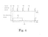
- the groove 27 is arranged at the same radial position as that of the first detection sensor 36. Therefore, rotation of the rotating portion 2 causes the groove 27 to pass a region on the lower surface 242 to which the light is emitted from the first detection sensor 36. Accordingly, as illustrated in a lower portion of Fig. 4 , one pulse P1 is outputted from the first detection sensor 36 in a period T1 during which the rotating portion 2 rotates one time.
- the pulse P1 occurs only in a partial angular range in the circumferential direction, and can therefore be said to be uneven in the circumferential direction.
- each of the auxiliary grooves 28 is arranged at the same radial position as that of the second detection sensor 37. Therefore, the rotation of the rotating portion 2 causes the auxiliary grooves 28 to successively pass a region on the lower surface 242 to which the light is emitted from the second detection sensor 37. Accordingly, as illustrated in an upper portion of Fig. 4 , four pulses P2 are outputted from the second detection sensor 37 in the period T1 during which the rotating portion 2 rotates one time.
- the circumferential angular position of each of the auxiliary grooves 28 with respect to a predetermined reference position on the lower surface 242 is previously known. Therefore, the pulse P2, which occurs for each auxiliary groove 28, indicates a rotation angle of the mirror portion 24.
- the auxiliary grooves 28 define and serve as a plurality of rotation angle indicating portions.
- each of the auxiliary grooves 28 indicates the angular position of a separate one of the boundary portions 263. Accordingly, the pulse P2 obtained by the second detection sensor 37 indicates a change in the mirror surfaces 262 at the position of the second detection sensor 37.
- one rotation of the rotating portion 2 is detected as a result of the groove 27, which defines and serves as the balance correction portion as well, passing the region to which the light is emitted from the first detection sensor 36.
- the groove 27, which is also used for the purpose of balance correction to detect the rotation of the rotating portion 2
- a reduction in the number of parts of the mirror rotating apparatus 1 is achieved compared to a case where another member, such as, for example, a magnet, is attached to the lower surface 242 as a portion to be detected.
- a reduction in the number of steps in a process of manufacturing the mirror rotating apparatus 1 is also achieved compared to the case where the other member is attached to the lower surface 242 as the portion to be detected, or the case where, for example, a predetermined pattern is printed on the lower surface 242.
- the auxiliary grooves 28 and the second detection sensor 37 are preferably provided in the mirror rotating apparatus 1. The changes in the mirror surfaces 262 are easily detected by the auxiliary grooves 28 successively passing the region to which the light is emitted from the second detection sensor 37.
- the mirror portion 24 is fixed to the shaft 21, and this makes it easy for a center of the rotation of the mirror portion 24 to coincide with that of the shaft 21, that is, to improve concentricity of the mirror portion 24 with the rotation axis J1.
- most of the rotor holder 22 is arranged inside the recessed portion 25 of the mirror portion 24, which opens toward the rotor holder 22. This leads to a reduction in the thickness of the mirror rotating apparatus 1.
- an outer circumferential surface of a rotor holder 22 preferably is fixed to an inner circumferential surface 251 of a recessed portion 25 of a mirror portion 24.
- the mirror portion 24 is securely fixed to the rotor holder 22 over a large area of the inner circumferential surface 251 of the recessed portion 25.
- an outer circumferential surface of a rotor holder 22 preferably is fixed to an inner circumferential surface 251 of a recessed portion 25 of a mirror portion 24.
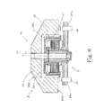
- Fig. 6 is a vertical cross-sectional view of the mirror rotating apparatus 1a according to a second preferred embodiment of the present invention.
- the mirror rotating apparatus 1a illustrated in Fig. 6 is different from the mirror rotating apparatus 1 illustrated in Fig. 1 in that one projection 27a and a plurality of auxiliary projections 28a are preferably provided in place of the groove 27 and the auxiliary grooves 28, respectively.
- the mirror rotating apparatus 1a illustrated in Fig. 6 is preferably otherwise similar in structure to the mirror rotating apparatus 1 illustrated in Fig. 1 . Accordingly, like members or portions are designated by like reference numerals, and redundant description is omitted.
- Fig. 7 is a bottom view of the mirror portion 24.
- the one projection 27a which is arranged to extend in the circumferential direction, and the plurality of auxiliary projections 28a are provided in a lower surface 242 of a mirror portion 24.
- Each of the projection 27a and the auxiliary projections 28a is arranged to project downward from the lower surface 242.
- the projection 27a is arranged to overlap with a mirror surface 262 having the greatest surface inclination angle, that is, the mirror surface 262 on a right-hand side in Fig. 7 , in a plan view.
- the projection 27a is arranged to overlap also with a mirror surface 262 having the second greatest surface inclination angle, that is, the mirror surface 262 on an upper side in Fig. 7 .
- a predetermined cross section of the mirror portion 24 perpendicular to a rotation axis J1 is defined as a cross section S1. If the projection 27a were not provided, the center of gravity of the mirror portion 24 would be displaced toward a boundary portion 263a with respect to which the boundary-axis distance is the greatest in the cross section S1. Accordingly, in the mirror portion 24 illustrated in Fig. 7 , the projection 27a is provided on an opposite side of the rotation axis J1 with respect to the above boundary portion 263a.
- a boundary portion 263b with respect to which the boundary-axis distance is the smallest will be referred to as a "closest boundary portion" 263b.
- the projection 27a is preferably arranged on a side of the rotation axis J1 closer to the closest boundary portion 263b. Provision of the projection 27a moves the center of gravity of the mirror portion 24 closer to the rotation axis J1 when compared to the case where the projection 27a is not provided. As described above, the projection 27a in the mirror portion 24 illustrated in Fig. 7 serves as a balance correction portion to move the center of gravity of the mirror portion 24 closer to the rotation axis J1.
- At least a portion of the projection 27a is preferably arranged in a region in the lower surface 242, the region extending in each circumferential direction by an angular range of about 90 degrees from a line which joins the rotation axis J1 and the closest boundary portion 263b in the cross section S1.
- the auxiliary projections 28a are arranged at the same positions as those of the auxiliary grooves 28 illustrated in Fig. 3 .
- each of the auxiliary projections 28a preferably have the same shape as that of each of the auxiliary grooves 28 illustrated in Fig. 3 in a plan view.
- the projection 27a is preferably arranged at the same radial position as that of a first detection sensor 36. Therefore, rotation of a rotating portion 2 causes the projection 27a to pass a region on the lower surface 242 to which light is emitted from the first detection sensor 36. Accordingly, one pulse is outputted from the first detection sensor 36 in a period during which the rotating portion 2 rotates one time.
- each of the auxiliary projections 28a is preferably arranged at the same radial position as that of a second detection sensor 37. Therefore, the rotation of the rotating portion 2 causes the auxiliary projections 28a to successively pass a region on the lower surface 242 to which light is emitted from the second detection sensor 37.
- each of the auxiliary projections 28a also serves as a rotation angle indicating portion.
- the mirror rotating apparatus 1a As described above, in the mirror rotating apparatus 1a, one rotation of the rotating portion 2 is detected as a result of the projection 27a, which also serves as the balance correction portion, passing the region to which the light is emitted from the first detection sensor 36.
- the projection 27a which is also used for the purpose of balance correction, to detect the rotation of the rotating portion 2
- a reduction in the number of parts of the mirror rotating apparatus 1a is achieved, and a reduction in a production cost of the mirror rotating apparatus 1a is achieved.
- the auxiliary projections 28a and the second detection sensor 37 are provided in the mirror rotating apparatus 1a. Changes in the mirror surfaces 262 are easily detected by the auxiliary projections 28a successively passing the region to which the light is emitted from the second detection sensor 37.
- each of the above-described mirror rotating apparatuses 1 and 1a may be modified in a variety of manners.
- the above-described method of using the balance correction portion to detect the rotation of the rotating portion 2 is applicable to mirror portions 24 in a variety of shapes and the center of gravity of which is positioned away from the rotation axis J1 in the case where the balance correction portion is not provided therein.
- the center of gravity of the mirror portion 24 tends to be located away from the rotation axis J1.
- each mirror portion 24 each of whose mirror surfaces 262 has the same shape and the same surface inclination angle and in which a rotation axis J1 is displaced from a center of the mirror portion 24.
- the external shape of each mirror portion 24 in a plan view may not necessarily be quadrilateral.
- the number of mirror surfaces 262 included in the mirror portion 24 may be three or more than four, if so desired.
- a plurality of grooves 27 or a plurality of projections 27a may also be defined in the mirror portion 24 depending on a mode of balance correction in the mirror rotating apparatus 1 or 1a.
- the plurality of grooves 27 or the plurality of projections 27a define and serve as a plurality of balance correction portions to move the center of gravity of the mirror portion 24 closer to the rotation axis J1 than in the case where the plurality of balance correction portions are not provided.
- one rotation of the rotating portion 2 is detected by the first detection sensor 36 based on a plurality of pulses due to the plurality of balance correction portions.
- the rotation of the rotating portion 2 should cause only one balance correction portion to pass the region to which the light is emitted from the first detection sensor 36.
- the balance correction portion(s) may alternatively be provided in the inner circumferential surface 251 of the recessed portion 25 or the lower side surface (s) 261 of the mirror portion 24, if so desired.
- the first detection sensor 36 is configured such that the first detection sensor 36 is capable of emitting light toward the inner circumferential surface 251 or the lower side surface(s) 261, i.e., the rotation detection surface, and receiving the light reflected therefrom.
- the rotation angle indicating portions may also be provided in the inner circumferential surface 251 of the recessed portion 25 or the lower side surfaces 261. In this case, the rotation angle indicating portions are arranged in the circumferential direction such that each of the rotation angle indicating portions is arranged at an axial position different from that of the balance correction portion(s).
- the plurality of auxiliary grooves 28 may be replaced with the plurality of auxiliary projections 28a.
- the plurality of auxiliary projections 28a may be replaced with the plurality of auxiliary grooves 28.
- both an auxiliary groove(s) 28 and an auxiliary projection(s) 28a may be provided, if so desired.
- a line which joins the rotation axis J1 and the boundary portion 263 between each pair of two circumferentially adjacent mirror surfaces 262 of the plurality of mirror surfaces 262 is defined as a "boundary-axis imaginary line”.
- each of the auxiliary grooves 28 and the auxiliary projections 28a is referred to as the "rotation angle indicating portion”.
- a circumferential angle between the boundary-axis imaginary line for each of the plurality of boundary portions 263 and the rotation angle indicating portion adjacent, in a clockwise direction, to the boundary-axis imaginary line for the boundary portion 263 should be equal.
- each of the plurality of rotation angle indicating portions is arranged on a separate one of the plurality of boundary-axis imaginary lines in a plan view. This makes it easy to detect a change in the mirror surfaces 262.
- the number of rotation angle indicating portions provided in the mirror portion 24 may be different from the number of mirror surfaces 262 of the mirror portion 24.
- the rotation angle of the mirror portion 24 is detected based on the plurality of rotation angle indicating portions.
- angular positions at which changes in the mirror surfaces 262 occur are previously known, it is possible to indirectly detect the changes in the mirror surfaces 262.
- each of the balance correction portion(s) and the rotation angle indicating portions should be arranged at an axial level lower than an axial level of the cover portion 222 of the rotor holder 22, that is, on a side of the cover portion 222 of the rotor holder 22 closer to the one end portion of the shaft 21 at which the shaft 21 is supported by the stationary portion 3.
- Mirror rotating apparatuses according to preferred embodiments of the present invention can be used in a variety of applications.
Landscapes
- Physics & Mathematics (AREA)
- General Physics & Mathematics (AREA)
- Optics & Photonics (AREA)
- Engineering & Computer Science (AREA)
- General Engineering & Computer Science (AREA)
- Mechanical Engineering (AREA)
- Mechanical Optical Scanning Systems (AREA)
- Length Measuring Devices By Optical Means (AREA)
- Laser Beam Printer (AREA)
- Facsimile Scanning Arrangements (AREA)
- Rear-View Mirror Devices That Are Mounted On The Exterior Of The Vehicle (AREA)
Abstract
Description
- The present invention relates to a mirror rotating apparatus.
- A polygon mirror is often used as a laser scanning component in a printer, a digital copy machine, or the like.
JP-H10-325937A JP-H10-325937A JP-2002-218721A - Meanwhile, in a scanner motor for use in a video tape recorder as described in
JP-H5-49225A - In a case where the detected portions are provided by the printing process in a mirror rotating apparatus arranged to rotate a mirror portion including a plurality of mirror surfaces as in the case of the scanner motor described in
JP-H5-49225A - Preferred embodiments of the present invention reduce a production cost of a mirror rotating apparatus in which detection of rotation of a rotating portion is performed.
- A mirror rotating apparatus according to a preferred embodiment of the present invention includes a stationary portion and a rotating portion configured to rotate about a rotation axis extending in a vertical direction with respect to the stationary portion. The stationary portion includes a stator and a detection sensor configured to detect rotation of the rotating portion. The rotating portion includes a rotor magnet arranged radially opposite the stator, and a mirror portion whose outside surface includes a plurality of mirror surfaces each of which is arranged to face radially outward. The mirror portion includes a rotation detection surface arranged opposite to the detection sensor, and a balance correction portion defined by a groove or a projection extending in a circumferential direction in the rotation detection surface. The balance correction portion is arranged to make a center of gravity of the mirror portion closer to the rotation axis when compared to a case where the balance correction portion is not provided. The detection sensor is configured to emit light toward the rotation detection surface and receive the light reflected from the rotation detection surface. The rotation of the rotating portion causes the balance correction portion to pass a region to which the light is emitted from the detection sensor.
- In the mirror rotating apparatus according to the above preferred embodiment of the present invention, the balance correction portion is used to detect the rotation of the rotating portion, and thus a reduction in a production cost of the mirror rotating apparatus is achieved.
- The above and other elements, features, steps, characteristics and advantages of the present invention will become more apparent from the following detailed description of the preferred embodiments with reference to the attached drawings.
-
-
Fig. 1 is a vertical cross-sectional view of a mirror rotating apparatus according to a first preferred embodiment of the present invention. -
Fig. 2 is a plan view of a mirror portion according to the first preferred embodiment of the present invention. -
Fig. 3 is a bottom view of the mirror portion according to the first preferred embodiment of the present invention. -
Fig. 4 is a diagram illustrating pulses outputted from detection sensors according to the first preferred embodiment of the present invention. -
Fig. 5 is a vertical cross-sectional view of a mirror rotating apparatus according to a modification of the first preferred embodiment of the present invention. -
Fig. 6 is a vertical cross-sectional view of a mirror rotating apparatus according to a second preferred embodiment of the present invention. -
Fig. 7 is a bottom view of a mirror portion according to the second preferred embodiment of the present invention. - It is assumed herein that a vertical direction is defined as a direction in which a rotation axis of a mirror rotating apparatus extends, and that an upper side and a lower side along the rotation axis in
Fig. 1 are referred to simply as an upper side and a lower side, respectively. It should be noted, however, that the above definitions of the vertical direction and the upper and lower sides should not be construed to restrict relative positions or directions of different members or portions when the mirror rotating apparatus is actually installed in a device. Also note that a direction parallel or substantially parallel to the rotation axis is referred to by the term "axial direction", "axial", or "axially", that radial directions centered on the rotation axis are simply referred to by the term "radial direction", "radial", or "radially", and that a circumferential direction about the rotation axis is simply referred to by the term "circumferential direction", "circumferential", or "circumferentially". -
Fig. 1 is a vertical cross-sectional view of amirror rotating apparatus 1 according to a first preferred embodiment of the present invention. Themirror rotating apparatus 1 includes a rotatingportion 2 and astationary portion 3. The rotatingportion 2 is arranged to rotate about a rotation axis J1. Thestationary portion 3 is arranged to rotatably support the rotatingportion 2. - The rotating
portion 2 preferably includes a columnar or substantiallycolumnar shaft 21, arotor holder 22 substantially in the shape of a covered cylinder, anannular rotor magnet 23, and amirror portion 24. Theshaft 21 is arranged to have the rotation axis J1, which extends in the vertical direction, as a center thereof. Therotor holder 22 is fixed to theshaft 21, and is arranged to rotate about the rotation axis J1. Themirror portion 24 is fixed to an upper end portion of theshaft 21. - The
rotor holder 22 preferably includes an outercylindrical portion 221, acover portion 222, and an innercylindrical portion 223. An outer circumferential surface of therotor magnet 23 is fixed to an inner circumferential surface of the outercylindrical portion 221. Thecover portion 222 is preferably a flat plate extending from the outercylindrical portion 221 toward the rotation axis J1. The innercylindrical portion 223 extends axially downward from an inner edge of thecover portion 222. An inner circumferential surface of the innercylindrical portion 223 is fixed to an outer circumferential surface of theshaft 21. Note that therotor holder 22 may not necessarily be directly fixed to theshaft 21, but may instead be indirectly fixed to theshaft 21, for example, with another member fixed to theshaft 21 intervening therebetween. - The
stationary portion 3 preferably includes a cylindrical or substantiallycylindrical sleeve 31, ahousing 32, astator 33, amounting plate 34 in or substantially in the shape of a flat plate, acircuit board 35, afirst detection sensor 36, and asecond detection sensor 37. An inner circumferential surface of thesleeve 31, which is a bearing mechanism, is arranged to support a lower end portion of theshaft 21, i.e., one end portion of theshaft 21, such that theshaft 21 is rotatable about the rotation axis J1. Thesleeve 31 is preferably made of a sintered material, for example. Thehousing 32 preferably includes acylindrical portion 321 and abottom portion 322. An inner circumferential surface of thecylindrical portion 321 is arranged to hold an outer circumferential surface of thesleeve 31. Thebottom portion 322 is arranged to close a bottom portion of thecylindrical portion 321. An inner circumferential surface of thestator 33 is fixed to an outer circumferential surface of thecylindrical portion 321 of thehousing 32. Thestator 33 is arranged radially inside therotor magnet 23. An outer circumferential surface of thestator 33 is arranged radially opposite an inner circumferential surface of therotor magnet 23. As described above, a so-called outer-rotor motor is constructed in themirror rotating apparatus 1. Note that a so-called inner-rotor motor may alternatively be constructed in themirror rotating apparatus 1 if so desired. - The mounting
plate 34 is arranged axially below thestator 33. The mountingplate 34 includes an inner circumferential surface fixed to the outer circumferential surface of thecylindrical portion 321 of thehousing 32. Thecircuit board 35 is arranged on an upper surface of the mountingplate 34. Each of thefirst detection sensor 36 and thesecond detection sensor 37 is preferably inserted in through holes defined in the mountingplate 34 and thecircuit board 35, and is fixed to both the mountingplate 34 and thecircuit board 35. Depending a shape of themirror rotating apparatus 1, each of thefirst detection sensor 36 and thesecond detection sensor 37 may alternatively be fixed to an upper surface of thecircuit board 35. - The
first detection sensor 36 is preferably arranged radially outward of therotor holder 22, and is arranged opposite to alower surface 242 of themirror portion 24. Thefirst detection sensor 36 is configured to emit light toward thelower surface 242 and receive the light reflected from thelower surface 242. Thesecond detection sensor 37 is also preferably arranged radially outward of therotor holder 22, and is arranged opposite to thelower surface 242 of themirror portion 24. Similar to thefirst detection sensor 36, thesecond detection sensor 37 is configured to emit light toward thelower surface 242 and receive the light reflected from thelower surface 242. Each of thefirst detection sensor 36 and thesecond detection sensor 37 is configured to detect a change in intensity of the reflected light, that is, a change in reflectivity in a region to which the light is emitted. - Once a current is supplied from an external power supply (not shown) to the
stator 33, a magnetic field opposed to therotor magnet 23 is generated around thestator 33. Magnetic interaction between this magnetic field and therotor magnet 23 produces a force which drives therotating portion 2 to rotate about the rotation axis J1. At this time, as described below, rotation of themirror portion 24 is detected by thefirst detection sensor 36 and thesecond detection sensor 37 which emit the light toward thelower surface 242. Thus, thelower surface 242 of themirror portion 24 defines a rotation detection surface. -
Fig. 2 is a plan view of themirror portion 24. Referring toFig. 1 , themirror portion 24 includes thelower surface 242, which is arranged to extend perpendicularly or substantially perpendicularly to the axial direction, anupper surface 243 parallel or substantially parallel to thelower surface 242, and a throughhole 249 centered on the rotation axis J1. The upper end portion of theshaft 21, which projects upward from therotor holder 22 toward themirror portion 24, is preferably press fitted, for example, into the throughhole 249 to be fixed to themirror portion 24. Note that theshaft 21 may be fixed to themirror portion 24 through other methods such as, adhesion, ultrasonic welding, etc. - As illustrated in
Fig. 2 , thelower surface 242 is preferably arranged to have a rectangular or substantially rectangular external shape with the rotation axis J1 as a center, when viewed along the rotation axis J1, that is, in a plan view. In the plan view, the external shape of theupper surface 243 is rectangular, and the entireupper surface 243 is included in thelower surface 242. Each of four sides of the rectangular or substantially rectangularupper surface 243 is preferably parallel or substantially parallel to a corresponding one of four sides of the rectangularlower surface 242. A center of theupper surface 243 is spaced away from the rotation axis J1. - The
mirror portion 24 includes fouroutside surfaces 26 each of which is arranged to face radially outward. Referring toFig. 1 , eachoutside surface 26 preferably includes alower side surface 261 and anupper side surface 262. Thelower side surface 261 preferably is a rectangular or substantially rectangular flat surface extending upward from one side of thelower surface 242 in parallel or substantially in parallel with the rotation axis J1. Each of the four lower side surfaces 261 extending from the respective four sides of thelower surface 242 is preferably arranged to have the same axial dimension. Theupper side surface 262 is a flat surface extending from an upper side of thelower side surface 261 obliquely with respect to the rotation axis J1, and is joined to one side of theupper surface 243. As illustrated inFig. 2 , each of the four upper side surfaces 262 is joined to a separate one of the four sides of theupper surface 243. InFig. 2 , one of the upper side surfaces 262 is denoted by reference symbol "262a". As described above, themirror portion 24 includes a portion in or substantially in the shape of a quadrangular prism and surrounded by the four lower side surfaces 261, and a portion in or substantially in the shape of a prismoid and surrounded by the four upper side surfaces 262. Eachupper side surface 262 is subjected to a predetermined mirror finishing process. Hereinafter, eachupper side surface 262 will be referred to as a "mirror surface" 262. Note that theupper surface 243 may alternatively be in the shape of a polygon other than a quadrilateral. In this case, a plurality of mirror surfaces 262 are joined to all sides of the polygon, respectively. - Every two circumferentially adjacent mirror surfaces 262 have a
boundary portion 263 therebetween. Eachboundary portion 263 of themirror portion 24 illustrated inFig. 2 is a side shared by the two circumferentially adjacent mirror surfaces 262. Note that theboundary portion 263 may be a line-shaped surface having a uniform width and arranged between the two adjacent mirror surfaces 262. Such a surface may preferably be obtained, for example, by performing a chamfering process on a corner portion between the two mirror surfaces 262. - In the
mirror portion 24 illustrated inFig. 2 , the center of theupper surface 243 is spaced away from the rotation axis J1, that is, the center of thelower surface 242, by different distances in two directions along two sides of the rectangularupper surface 243 perpendicular or substantially perpendicular to each other. Accordingly, assuming that an angle at which eachmirror surface 262 is inclined with respect to the rotation axis J1 is defined as a surface inclination angle, the surface inclination angle of each of the mirror surfaces 262 is preferably different. In practice, the surface inclination angle of themirror surface 262 becomes smaller as the distance between the two parallel sides of themirror surface 262, that is, the sides which are not theboundary portions 263, as measured in a direction perpendicular to the rotation axis J1 becomes shorter. In themirror portion 24 illustrated inFig. 2 , themirror surface 262a on an upper side inFig. 2 has the smallest surface inclination angle, and themirror surface 262 on a left-hand side, themirror surface 262 on a lower side, and themirror surface 262 on a right-hand side inFig. 2 have progressively greater surface inclination angles in the order named. In addition, each of the mirror surfaces 262 preferably has a different shape when viewed along a normal to themirror surface 262. -
Fig. 3 is a bottom view of themirror portion 24. Thelower surface 242 of themirror portion 24 preferably includes a recessedportion 25, onegroove 27 arranged to extend in a circumferential direction, and a plurality ofauxiliary grooves 28. Thelower surface 242 is subjected to the mirror finishing process, and light reflectivity is high in a region excluding the recessedportion 25, thegroove 27, and theauxiliary grooves 28. Referring toFig. 1 , the recessedportion 25 preferably includes a cylindrical innercircumferential surface 251 centered on the rotation axis J1, and atop surface 252 perpendicular to the rotation axis J1. The innercircumferential surface 251 is arranged radially opposite the outercylindrical portion 221. Thetop surface 252 is arranged axially opposite thecover portion 222. - Referring to
Fig. 3 , anedge 271 of thegroove 27 at one circumferential end is straight, and extends in a radial direction centered on the rotation axis J1. Themirror portion 24 is configured to rotate in a clockwise direction about the rotation axis J1 inFig. 3 . Theedge 271 is a forward edge of thegroove 27 with respect to a rotation direction of themirror portion 24. Thegroove 27 is preferably arranged to overlap with themirror surface 262a having the smallest surface inclination angle in a plan view. In addition, thegroove 27 is also preferably arranged to overlap with themirror surface 262 having the second smallest surface inclination angle, that is, themirror surface 262 on a left-hand side inFig. 3 . - Here, a predetermined cross section of the
mirror portion 24 perpendicular to the rotation axis J1 and taken above thelower side surface 261 is defined as a cross section S1. InFig. 3 , the external shape of the cross section S1 is represented by a rectangle drawn in a chain double-dashed line denoted by reference symbol "S1". The distance between the rotation axis J1 and theboundary portion 263 between each pair of two circumferentially adjacent mirror surfaces 262 of the plurality of mirror surfaces 262 is defined as a "boundary-axis distance". In the cross section S1, the boundary-axis distance is different with respect to eachboundary portion 263. - If the
groove 27 were not provided, the center of gravity of themirror portion 24 would be spaced away from the rotation axis J1 toward themirror surface 262a having the smallest surface inclination angle and themirror surface 262 having the second smallest surface inclination angle. In other words, in the cross section S1, the center of gravity of themirror portion 24 would be displaced toward theboundary portion 263a with respect to which the boundary-axis distance is the greatest. Hereinafter, theboundary portion 263a with respect to which the boundary-axis distance is the greatest will be referred to also as a "farthest boundary portion" 263a. In theactual mirror portion 24, thegroove 27 is arranged on a side of the rotation axis J1 closer to thefarthest boundary portion 263a. Provision of thegroove 27 moves the center of gravity of themirror portion 24 closer to the rotation axis J1 when compared to a case where thegroove 27 is not provided. As described above, thegroove 27 in themirror portion 24 illustrated inFig. 3 serves as a balance correction portion to move the center of gravity of themirror portion 24 closer to the rotation axis J1. From the viewpoint of balance correction, at least a portion of thegroove 27 is preferably arranged in a region in thelower surface 242, the region extending in each circumferential direction by an angular range of about 90 degrees from a line which joins the rotation axis J1 and thefarthest boundary portion 263a in the cross section S1. Thegroove 27 is defined, for example, by a cutting process. - The
auxiliary grooves 28 are arranged in the circumferential direction in thelower surface 242 such that eachauxiliary groove 28 is arranged at a radial position different from that of thegroove 27. The number ofauxiliary grooves 28 included in themirror portion 24 is equal to the number of mirror surfaces 262. Each of theauxiliary grooves 28 is preferably defined, for example, by a cutting process. Eachauxiliary groove 28 is arranged to overlap with one of theboundary portions 263 in a plan view. In more detail, eachauxiliary groove 28 includes two straight edges each of which is arranged to extend along theboundary portion 263 in the plan view. Of the two straight edges, anedge 281 of theauxiliary groove 28 which is forward with respect to the rotation direction of themirror portion 24 is arranged to axially overlap with theboundary portion 263. One of theauxiliary grooves 28 is continuous with thegroove 27. Theauxiliary grooves 28 are preferably arranged evenly or substantially evenly in the circumferential direction, and therefore, provision of theauxiliary grooves 28 does not cause a significant movement of the center of gravity of themirror portion 24. In themirror portion 24 according to a preferred embodiment of the present invention, the center of gravity of themirror portion 24 lies on or substantially on the rotation axis J1, with thegroove 27 and theauxiliary grooves 28 defined in themirror portion 24. - Referring to
Fig. 1 , in themirror rotating apparatus 1, thegroove 27 is arranged at the same radial position as that of thefirst detection sensor 36. Therefore, rotation of therotating portion 2 causes thegroove 27 to pass a region on thelower surface 242 to which the light is emitted from thefirst detection sensor 36. Accordingly, as illustrated in a lower portion ofFig. 4 , one pulse P1 is outputted from thefirst detection sensor 36 in a period T1 during which therotating portion 2 rotates one time. The pulse P1 occurs only in a partial angular range in the circumferential direction, and can therefore be said to be uneven in the circumferential direction. - In addition, each of the
auxiliary grooves 28 is arranged at the same radial position as that of thesecond detection sensor 37. Therefore, the rotation of therotating portion 2 causes theauxiliary grooves 28 to successively pass a region on thelower surface 242 to which the light is emitted from thesecond detection sensor 37. Accordingly, as illustrated in an upper portion ofFig. 4 , four pulses P2 are outputted from thesecond detection sensor 37 in the period T1 during which therotating portion 2 rotates one time. The circumferential angular position of each of theauxiliary grooves 28 with respect to a predetermined reference position on thelower surface 242 is previously known. Therefore, the pulse P2, which occurs for eachauxiliary groove 28, indicates a rotation angle of themirror portion 24. Thus, theauxiliary grooves 28 define and serve as a plurality of rotation angle indicating portions. In themirror portion 24 illustrated inFig. 3 , each of theauxiliary grooves 28 indicates the angular position of a separate one of theboundary portions 263. Accordingly, the pulse P2 obtained by thesecond detection sensor 37 indicates a change in the mirror surfaces 262 at the position of thesecond detection sensor 37. - As described above, in the
mirror rotating apparatus 1, one rotation of therotating portion 2 is detected as a result of thegroove 27, which defines and serves as the balance correction portion as well, passing the region to which the light is emitted from thefirst detection sensor 36. Thus, by using thegroove 27, which is also used for the purpose of balance correction, to detect the rotation of therotating portion 2, a reduction in the number of parts of themirror rotating apparatus 1 is achieved compared to a case where another member, such as, for example, a magnet, is attached to thelower surface 242 as a portion to be detected. Moreover, a reduction in the number of steps in a process of manufacturing themirror rotating apparatus 1 is also achieved compared to the case where the other member is attached to thelower surface 242 as the portion to be detected, or the case where, for example, a predetermined pattern is printed on thelower surface 242. This leads to a reduction in a production cost of themirror rotating apparatus 1. Further, theauxiliary grooves 28 and thesecond detection sensor 37 are preferably provided in themirror rotating apparatus 1. The changes in the mirror surfaces 262 are easily detected by theauxiliary grooves 28 successively passing the region to which the light is emitted from thesecond detection sensor 37. - In the
mirror rotating apparatus 1 illustrated inFig. 1 , themirror portion 24 is fixed to theshaft 21, and this makes it easy for a center of the rotation of themirror portion 24 to coincide with that of theshaft 21, that is, to improve concentricity of themirror portion 24 with the rotation axis J1. In addition, most of therotor holder 22 is arranged inside the recessedportion 25 of themirror portion 24, which opens toward therotor holder 22. This leads to a reduction in the thickness of themirror rotating apparatus 1. - Referring to
Fig. 5 , according to a modification of the first preferred embodiment, an outer circumferential surface of arotor holder 22 preferably is fixed to an innercircumferential surface 251 of a recessedportion 25 of amirror portion 24. In this case, themirror portion 24 is securely fixed to therotor holder 22 over a large area of the innercircumferential surface 251 of the recessedportion 25. As a result, a reduction in vibrations of themirror portion 24 is achieved. In a modification of amirror rotating apparatus 1a, which will be described below, an outer circumferential surface of arotor holder 22 preferably is fixed to an innercircumferential surface 251 of a recessedportion 25 of amirror portion 24. -
Fig. 6 is a vertical cross-sectional view of themirror rotating apparatus 1a according to a second preferred embodiment of the present invention. Themirror rotating apparatus 1a illustrated inFig. 6 is different from themirror rotating apparatus 1 illustrated inFig. 1 in that one projection 27a and a plurality ofauxiliary projections 28a are preferably provided in place of thegroove 27 and theauxiliary grooves 28, respectively. Themirror rotating apparatus 1a illustrated inFig. 6 is preferably otherwise similar in structure to themirror rotating apparatus 1 illustrated inFig. 1 . Accordingly, like members or portions are designated by like reference numerals, and redundant description is omitted. -
Fig. 7 is a bottom view of themirror portion 24. The one projection 27a, which is arranged to extend in the circumferential direction, and the plurality ofauxiliary projections 28a are provided in alower surface 242 of amirror portion 24. Each of the projection 27a and theauxiliary projections 28a is arranged to project downward from thelower surface 242. The projection 27a is arranged to overlap with amirror surface 262 having the greatest surface inclination angle, that is, themirror surface 262 on a right-hand side inFig. 7 , in a plan view. In addition, the projection 27a is arranged to overlap also with amirror surface 262 having the second greatest surface inclination angle, that is, themirror surface 262 on an upper side inFig. 7 . - Here, as with the case of
Fig. 3 , a predetermined cross section of themirror portion 24 perpendicular to a rotation axis J1 is defined as a cross section S1. If the projection 27a were not provided, the center of gravity of themirror portion 24 would be displaced toward aboundary portion 263a with respect to which the boundary-axis distance is the greatest in the cross section S1. Accordingly, in themirror portion 24 illustrated inFig. 7 , the projection 27a is provided on an opposite side of the rotation axis J1 with respect to theabove boundary portion 263a. Hereinafter, aboundary portion 263b with respect to which the boundary-axis distance is the smallest will be referred to as a "closest boundary portion" 263b. The projection 27a is preferably arranged on a side of the rotation axis J1 closer to theclosest boundary portion 263b. Provision of the projection 27a moves the center of gravity of themirror portion 24 closer to the rotation axis J1 when compared to the case where the projection 27a is not provided. As described above, the projection 27a in themirror portion 24 illustrated inFig. 7 serves as a balance correction portion to move the center of gravity of themirror portion 24 closer to the rotation axis J1. From the viewpoint of balance correction, at least a portion of the projection 27a is preferably arranged in a region in thelower surface 242, the region extending in each circumferential direction by an angular range of about 90 degrees from a line which joins the rotation axis J1 and theclosest boundary portion 263b in the cross section S1. Theauxiliary projections 28a are arranged at the same positions as those of theauxiliary grooves 28 illustrated inFig. 3 . Moreover, each of theauxiliary projections 28a preferably have the same shape as that of each of theauxiliary grooves 28 illustrated inFig. 3 in a plan view. - Referring to
Fig. 6 , the projection 27a is preferably arranged at the same radial position as that of afirst detection sensor 36. Therefore, rotation of arotating portion 2 causes the projection 27a to pass a region on thelower surface 242 to which light is emitted from thefirst detection sensor 36. Accordingly, one pulse is outputted from thefirst detection sensor 36 in a period during which therotating portion 2 rotates one time. In addition, each of theauxiliary projections 28a is preferably arranged at the same radial position as that of asecond detection sensor 37. Therefore, the rotation of therotating portion 2 causes theauxiliary projections 28a to successively pass a region on thelower surface 242 to which light is emitted from thesecond detection sensor 37. Accordingly, four pulses are outputted from thesecond detection sensor 37 in the period during which therotating portion 2 rotates one time. Similar to each of theauxiliary grooves 28 illustrated inFig. 3 , each of theauxiliary projections 28a also serves as a rotation angle indicating portion. - As described above, in the
mirror rotating apparatus 1a, one rotation of therotating portion 2 is detected as a result of the projection 27a, which also serves as the balance correction portion, passing the region to which the light is emitted from thefirst detection sensor 36. Thus, by using the projection 27a, which is also used for the purpose of balance correction, to detect the rotation of therotating portion 2, a reduction in the number of parts of themirror rotating apparatus 1a is achieved, and a reduction in a production cost of themirror rotating apparatus 1a is achieved. Further, theauxiliary projections 28a and thesecond detection sensor 37 are provided in themirror rotating apparatus 1a. Changes in the mirror surfaces 262 are easily detected by theauxiliary projections 28a successively passing the region to which the light is emitted from thesecond detection sensor 37. - Note that the structure of each of the above-described
mirror rotating apparatuses - The above-described method of using the balance correction portion to detect the rotation of the
rotating portion 2 is applicable to mirrorportions 24 in a variety of shapes and the center of gravity of which is positioned away from the rotation axis J1 in the case where the balance correction portion is not provided therein. For example, in amirror portion 24 in which an angle at which one of a plurality ofmirror surface 262 is inclined with respect to the rotation axis J1 is different from an angle at which at least one of the other mirror surfaces 262 is inclined with respect to the rotation axis J1, the center of gravity of themirror portion 24 tends to be located away from the rotation axis J1. In addition, also in amirror portion 24 in which one of a plurality of mirror surfaces 262 is different in shape from at least one of the other mirror surfaces 262, the center of gravity of themirror portion 24 tends to be spaced away from the rotation axis J1. Therefore, for thesemirror portions 24, provision of the balance correction portion and use of the balance correction portion to detect the rotation of therotating portion 2 are suitable. - In addition, the above-described method is also applicable to a
mirror portion 24 each of whose mirror surfaces 262 has the same shape and the same surface inclination angle and in which a rotation axis J1 is displaced from a center of themirror portion 24. Note that the external shape of eachmirror portion 24 in a plan view may not necessarily be quadrilateral. Also note that the number of mirror surfaces 262 included in themirror portion 24 may be three or more than four, if so desired. - Note that, in a modification of each of the
mirror rotating apparatuses grooves 27 or a plurality of projections 27a may also be defined in themirror portion 24 depending on a mode of balance correction in themirror rotating apparatus grooves 27 or the plurality of projections 27a define and serve as a plurality of balance correction portions to move the center of gravity of themirror portion 24 closer to the rotation axis J1 than in the case where the plurality of balance correction portions are not provided. Moreover, one rotation of therotating portion 2 is detected by thefirst detection sensor 36 based on a plurality of pulses due to the plurality of balance correction portions. Note that, from the viewpoint of easily detecting one rotation of therotating portion 2 and a home position of therotating portion 2 with thefirst detection sensor 36, it is preferable that the rotation of therotating portion 2 should cause only one balance correction portion to pass the region to which the light is emitted from thefirst detection sensor 36. - Note that, depending on a shape of the mirror rotating apparatus, the balance correction portion(s) may alternatively be provided in the inner
circumferential surface 251 of the recessedportion 25 or the lower side surface (s) 261 of themirror portion 24, if so desired. In this case, thefirst detection sensor 36 is configured such that thefirst detection sensor 36 is capable of emitting light toward the innercircumferential surface 251 or the lower side surface(s) 261, i.e., the rotation detection surface, and receiving the light reflected therefrom. Also note that the rotation angle indicating portions may also be provided in the innercircumferential surface 251 of the recessedportion 25 or the lower side surfaces 261. In this case, the rotation angle indicating portions are arranged in the circumferential direction such that each of the rotation angle indicating portions is arranged at an axial position different from that of the balance correction portion(s). - Note that, in the
mirror rotating apparatus 1 illustrated inFig. 1 , the plurality ofauxiliary grooves 28 may be replaced with the plurality ofauxiliary projections 28a. Also note that, in themirror rotating apparatus 1a illustrated inFig. 6 , the plurality ofauxiliary projections 28a may be replaced with the plurality ofauxiliary grooves 28. Also note that, in each of themirror rotating apparatuses - Here, in the predetermined cross section S1 of the
mirror portion 24 perpendicular to the rotation axis J1, a line which joins the rotation axis J1 and theboundary portion 263 between each pair of two circumferentially adjacent mirror surfaces 262 of the plurality of mirror surfaces 262 is defined as a "boundary-axis imaginary line". In addition, each of theauxiliary grooves 28 and theauxiliary projections 28a is referred to as the "rotation angle indicating portion". In this case, regarding themirror portion 24, it is preferable that a circumferential angle between the boundary-axis imaginary line for each of the plurality ofboundary portions 263 and the rotation angle indicating portion adjacent, in a clockwise direction, to the boundary-axis imaginary line for theboundary portion 263 should be equal. This makes it possible to detect a change in the mirror surfaces 262 at a predetermined position. More preferably, as in each of themirror rotating apparatuses lower surface 242 of themirror portion 24, each of the plurality of rotation angle indicating portions is arranged on a separate one of the plurality of boundary-axis imaginary lines in a plan view. This makes it easy to detect a change in the mirror surfaces 262. - Note that the number of rotation angle indicating portions provided in the
mirror portion 24 may be different from the number of mirror surfaces 262 of themirror portion 24. For example, in amirror portion 24 including fourmirror surfaces 262, six rotation angle indicating portions may be arranged at equal or substantially equal angular intervals in the circumferential direction, if so desired. In this case, the rotation angle of themirror portion 24 is detected based on the plurality of rotation angle indicating portions. Moreover, because angular positions at which changes in the mirror surfaces 262 occur are previously known, it is possible to indirectly detect the changes in the mirror surfaces 262. - From the viewpoint of reducing the thickness of each of the
mirror rotating apparatuses rotor holder 22 should be arranged inside the recessedportion 25. Moreover, it is also preferable that each of the balance correction portion(s) and the rotation angle indicating portions should be arranged at an axial level lower than an axial level of thecover portion 222 of therotor holder 22, that is, on a side of thecover portion 222 of therotor holder 22 closer to the one end portion of theshaft 21 at which theshaft 21 is supported by thestationary portion 3. - Note that features of the above-described preferred embodiments and the modifications thereof may be combined appropriately as long as no conflict arises.
- Mirror rotating apparatuses according to preferred embodiments of the present invention can be used in a variety of applications.
- While preferred embodiments of the present invention have been described above, it is to be understood that variations and modifications will be apparent to those skilled in the art without departing from the scope and spirit of the present invention. The scope of the present invention, therefore, is to be determined solely by the following claims.
Claims (15)
- A mirror rotating apparatus comprising:a stationary portion (3); anda rotating portion (2) configured to rotate about a rotation axis (J1) extending in a vertical direction with respect to the stationary portion (3); whereinthe stationary portion (3) includes:a stator (33); anda detection sensor (36) configured to detect rotation of the rotating portion (2);the rotating portion (2) includes:a rotor magnet (23) arranged radially opposite to the stator (33); anda mirror portion (24) whose outside surface includes a plurality of mirror surfaces (262) each of which is arranged to face radially outward;the mirror portion (24) includes:a rotation detection surface (261) arranged opposite to the detection sensor (36); anda balance correction portion (27, 27a) defined by a groove (27) or a projection (27a) extending in a circumferential direction in the rotation detection surface (261);the balance correction portion (27, 27a) is arranged such that a center of gravity of the mirror portion (24) is closer to the rotation axis (J1) as compared to a case where the balance correction portion (27, 27a) is not provided;the detection sensor (36) is configured to emit light toward the rotation detection surface (261) and receive the light reflected from the rotation detection surface (261); andthe rotation of the rotating portion (2) causes the balance correction portion (27, 27a) to pass a region to which the light is emitted from the detection sensor (36).
- The mirror rotating apparatus according to claim 1, wherein
the balance correction portion is defined by the groove (27); and
assuming that a distance between the rotation axis (J1) and a boundary portion between each pair of two circumferentially adjacent mirror surfaces (262) of the plurality of mirror surfaces (262) is defined as a boundary-axis distance, at least a portion of the balance correction portion (27) is located in a region in the rotation detection surface (261), the region extending in each circumferential direction by an angular range of about 90 degrees from a line joining the rotation axis (J1) and the boundary portion with respect to which the boundary-axis distance is greatest in a predetermined cross section of the mirror portion (24) perpendicular or substantially perpendicular to the rotation axis (J1). - The mirror rotating apparatus according to claim 1, wherein
the balance correction portion is defined by the projection (27a); and
assuming that a distance between the rotation axis (J1) and a boundary portion between each pair of two circumferentially adjacent mirror surfaces (262) of the plurality of mirror surfaces (262) is defined as a boundary-axis distance, at least a portion of the balance correction portion (27a) is located in a region in the rotation detection surface (261), the region extending in each circumferential direction by an angular range of about 90 degrees from a line joining the rotation axis (J1) and the boundary portion with respect to which the boundary-axis distance is smallest in a predetermined cross section of the mirror portion (24) perpendicular or substantially perpendicular to the rotation axis (J1). - The mirror rotating apparatus according to claim 2 or 3, wherein, in the predetermined cross section, the boundary-axis distance is different with respect to each boundary portion.
- The mirror rotating apparatus according to claim 4, wherein each of the plurality of mirror surfaces (262) includes a flat surface inclined with respect to the rotation axis (J1).
- The mirror rotating apparatus according to claim 5, wherein an angle at which one of the plurality of mirror surfaces (262) is inclined with respect to the rotation axis (J1) is different from an angle at which at least one of the other mirror surfaces is (262) inclined with respect to the rotation axis (J1).
- The mirror rotating apparatus according to claim 6, wherein at least one of the plurality of mirror surfaces (262) has a shape different from a shape of at least one of the other mirror surfaces (262).
- The mirror rotating apparatus according to claim 7, wherein the balance correction portion (27, 27a) is one in number.
- The mirror rotating apparatus according to claim 1, wherein
the mirror portion (24) further includes, as a plurality of rotation angle indicating portions, a plurality of auxiliary grooves (28) arranged in a circumferential direction in the rotation detection surface (261), each auxiliary groove (28) being arranged at a radial position different from a radial position of the balance correction portion (27, 27a) or at an axial position different from an axial position of the balance correction portion (27, 27a);
the stationary portion (3) further includes another detection sensor (37);
the another detection sensor (37) is configured to emit light toward the rotation detection surface (261) and receive the light reflected from the rotation detection surface (261); and
the rotation of the rotating portion (2) causes each of the plurality of rotation angle indicating portions to pass a region to which the light is emitted from the other detection sensor (36). - The mirror rotating apparatus according to claim 9, wherein, assuming that a line joining the rotation axis (J1) and a boundary portion between each pair of two circumferentially adjacent mirror surfaces (262) of the plurality of mirror surfaces (262) in a predetermined cross section of the mirror portion (24) perpendicular or substantially perpendicular to the rotation axis (J1) is defined as a boundary-axis imaginary line, a circumferential angle between the boundary-axis imaginary line for each boundary portion and the rotation angle indicating portion adjacent, in a clockwise direction, to the boundary-axis imaginary line for the boundary portion in the predetermined cross section is equal.
- The mirror rotating apparatus according to claim 10, wherein, in the rotation detection surface (261), each of the plurality of rotation angle indicating portions is arranged on a separate one of the boundary-axis imaginary lines in a plan view.
- The mirror rotating apparatus according to claim 11, wherein
the rotating portion (2) further includes:a rotor holder (22) which is in or substantially in a shape of a covered cylinder and to which the rotor magnet (23) is fixed, the rotor holder (22) including a cover portion (222); anda shaft (21) arranged to have the rotation axis (J1) as a center thereof, and fixed to the rotor holder (22);the stationary portion (3) is arranged to support one end portion of the shaft (21) such that the shaft (21) is rotatable;
an opposite end portion of the shaft (21) projects from the rotor holder (22) toward the mirror portion (24), and is fixed to the mirror portion (24); and
the detection sensor (36) is arranged radially outward of the rotor holder (22). - The mirror rotating apparatus according to claim 12, wherein
the mirror portion (24) includes a recessed portion (25) arranged to be open toward the rotor holder (22); and
the rotor magnet (23) is fixed to an inner circumferential surface (251) of the rotor holder (22) and is arranged radially opposite to the stator (33), and at least a portion of the rotor holder (22) is arranged inside the recessed portion (25). - The mirror rotating apparatus according to claim 11, wherein
the rotating portion (2) further includes:a rotor holder (22) in or substantially in a shape of a covered cylinder, and including an inner circumferential surface (251) to which the rotor magnet (23) is fixed, the rotor holder (22) including a cover portion (222); anda shaft (21) arranged to have the rotation axis (J1) as a center thereof, and fixed to the rotor holder (22);the stationary portion (3) is arranged to support one end portion of the shaft (21) such that the shaft (21) is rotatable;
the mirror portion (24) includes a recessed portion (25) arranged to be open toward the rotor holder (22);
an outer circumferential surface of the rotor holder (22) is fixed to an inner circumferential surface (251) of the recessed portion (25); and
the detection sensor (36) is arranged radially outward of the rotor holder (22). - The mirror rotating apparatus according to claim 13 or 14, wherein the balance correction portion (27, 27a) is arranged on a side of the cover portion (222) of the rotor holder (22) closer to the one end portion of the shaft (21).
Applications Claiming Priority (1)
| Application Number | Priority Date | Filing Date | Title |
|---|---|---|---|
| JP2013200981A JP6277406B2 (en) | 2013-09-27 | 2013-09-27 | Mirror rotating device |
Publications (1)
| Publication Number | Publication Date |
|---|---|
| EP2853935A1 true EP2853935A1 (en) | 2015-04-01 |
Family
ID=51726308
Family Applications (1)
| Application Number | Title | Priority Date | Filing Date |
|---|---|---|---|
| EP14186608.7A Withdrawn EP2853935A1 (en) | 2013-09-27 | 2014-09-26 | Mirror rotating apparatus |
Country Status (4)
| Country | Link |
|---|---|
| US (1) | US9207453B2 (en) |
| EP (1) | EP2853935A1 (en) |
| JP (1) | JP6277406B2 (en) |
| CN (2) | CN104516106B (en) |
Cited By (1)
| Publication number | Priority date | Publication date | Assignee | Title |
|---|---|---|---|---|
| CN110998408A (en) * | 2017-08-10 | 2020-04-10 | 浜松光子学株式会社 | Mirror device |
Families Citing this family (7)
| Publication number | Priority date | Publication date | Assignee | Title |
|---|---|---|---|---|
| JP6277406B2 (en) * | 2013-09-27 | 2018-02-14 | 日本電産株式会社 | Mirror rotating device |
| US9625709B1 (en) * | 2015-09-29 | 2017-04-18 | Datalogic Usa, Inc. | Reduced windage prismatic polygonal reflector for scanning |
| JP6682247B2 (en) | 2015-11-30 | 2020-04-15 | キヤノン株式会社 | Image forming device |
| JP2017198965A (en) * | 2016-04-28 | 2017-11-02 | 日本電産株式会社 | Rotary drive apparatus |
| US11063496B2 (en) * | 2016-08-05 | 2021-07-13 | Nidec Corporation | Vertical motor with resin bracket and cover having circuit board with wireless communication unit |
| JP2018169546A (en) * | 2017-03-30 | 2018-11-01 | 日本電産株式会社 | Housing, housing unit, and casing unit |
| JP7129203B2 (en) * | 2018-04-24 | 2022-09-01 | キヤノン株式会社 | Polygon mirrors, deflectors, optical scanning devices, and image forming devices |
Citations (9)
| Publication number | Priority date | Publication date | Assignee | Title |
|---|---|---|---|---|
| EP0040973A1 (en) * | 1980-05-22 | 1981-12-02 | Konica Corporation | An image reading out and recording apparatus |
| JPS63173017A (en) * | 1987-01-13 | 1988-07-16 | Matsushita Electric Ind Co Ltd | rotary drive device |
| EP0423812A2 (en) * | 1989-10-20 | 1991-04-24 | Canon Kabushiki Kaisha | Scanning optical apparatus |
| JPH0549225A (en) | 1991-08-09 | 1993-02-26 | Toshiba Corp | Brushless motor |
| US5245234A (en) * | 1990-12-28 | 1993-09-14 | Nippon Densan Corporation | Motor |
| JPH09126936A (en) * | 1995-11-06 | 1997-05-16 | Konica Corp | Dynamic-balance measuring instrument and dynamic-balance adjusting apparatus |
| JPH10325937A (en) | 1997-05-26 | 1998-12-08 | Olympus Optical Co Ltd | Injection molding of polygon mirror and method for preventing shake at its rotation |
| JP2002218721A (en) | 2001-01-12 | 2002-08-02 | Ricoh Co Ltd | High-speed rotating body, optical deflector using this high-speed rotating body, and balance correction method thereof |
| US20070146852A1 (en) * | 2005-12-26 | 2007-06-28 | Yukio Itami | Optical deflector, optical scanning apparatus, and image forming apparatus |
Family Cites Families (12)
| Publication number | Priority date | Publication date | Assignee | Title |
|---|---|---|---|---|
| JPS5963332U (en) * | 1982-10-21 | 1984-04-26 | コニカ株式会社 | rotating polygon mirror |
| US5903300A (en) * | 1993-01-12 | 1999-05-11 | Canon Kabushiki Kaisha | Deflection scanning apparatus having balance control |
| CN1154545A (en) * | 1995-09-29 | 1997-07-16 | 大宇电子株式会社 | Device for detecting cut of tape |
| JP3383187B2 (en) * | 1997-07-09 | 2003-03-04 | 株式会社三協精機製作所 | Optical deflector |
| JP3404495B2 (en) * | 1998-03-02 | 2003-05-06 | 富士通株式会社 | Polygon mirror, optical scanning device and bar code reader |
| US6242826B1 (en) * | 1998-07-27 | 2001-06-05 | Matsushita Electric Industrial Co., Ltd. | Spindle motor and disc driving apparatus comprising the same |
| TW200925802A (en) * | 2007-12-04 | 2009-06-16 | Sunonwealth Electr Mach Ind Co | Revolving polygon mirror counterweight structure of color laser printer |
| JP2010002751A (en) * | 2008-06-20 | 2010-01-07 | Canon Inc | Method of balance correction of optical deflector, optical deflector, optical scanner and image forming apparatus |
| JP2011002675A (en) * | 2009-06-19 | 2011-01-06 | Nidec Copal Electronics Corp | Method of correcting imbalance of tilt mirror |
| CN201819692U (en) * | 2010-08-20 | 2011-05-04 | 西南交通大学 | Single-code photoelectric encoder for detecting the speed and angle of rotation of rotating objects |
| JP2013015038A (en) * | 2011-06-30 | 2013-01-24 | Nippon Densan Corp | Fan |
| JP6277406B2 (en) * | 2013-09-27 | 2018-02-14 | 日本電産株式会社 | Mirror rotating device |
-
2013
- 2013-09-27 JP JP2013200981A patent/JP6277406B2/en not_active Expired - Fee Related
-
2014
- 2014-09-19 US US14/490,695 patent/US9207453B2/en not_active Expired - Fee Related
- 2014-09-22 CN CN201410487740.2A patent/CN104516106B/en not_active Expired - Fee Related
- 2014-09-22 CN CN201420545723.5U patent/CN204166193U/en not_active Expired - Fee Related
- 2014-09-26 EP EP14186608.7A patent/EP2853935A1/en not_active Withdrawn
Patent Citations (9)
| Publication number | Priority date | Publication date | Assignee | Title |
|---|---|---|---|---|
| EP0040973A1 (en) * | 1980-05-22 | 1981-12-02 | Konica Corporation | An image reading out and recording apparatus |
| JPS63173017A (en) * | 1987-01-13 | 1988-07-16 | Matsushita Electric Ind Co Ltd | rotary drive device |
| EP0423812A2 (en) * | 1989-10-20 | 1991-04-24 | Canon Kabushiki Kaisha | Scanning optical apparatus |
| US5245234A (en) * | 1990-12-28 | 1993-09-14 | Nippon Densan Corporation | Motor |
| JPH0549225A (en) | 1991-08-09 | 1993-02-26 | Toshiba Corp | Brushless motor |
| JPH09126936A (en) * | 1995-11-06 | 1997-05-16 | Konica Corp | Dynamic-balance measuring instrument and dynamic-balance adjusting apparatus |
| JPH10325937A (en) | 1997-05-26 | 1998-12-08 | Olympus Optical Co Ltd | Injection molding of polygon mirror and method for preventing shake at its rotation |
| JP2002218721A (en) | 2001-01-12 | 2002-08-02 | Ricoh Co Ltd | High-speed rotating body, optical deflector using this high-speed rotating body, and balance correction method thereof |
| US20070146852A1 (en) * | 2005-12-26 | 2007-06-28 | Yukio Itami | Optical deflector, optical scanning apparatus, and image forming apparatus |
Cited By (5)
| Publication number | Priority date | Publication date | Assignee | Title |
|---|---|---|---|---|
| CN110998408A (en) * | 2017-08-10 | 2020-04-10 | 浜松光子学株式会社 | Mirror device |
| CN110998408B (en) * | 2017-08-10 | 2023-03-28 | 浜松光子学株式会社 | Mirror device |
| US11733511B2 (en) | 2017-08-10 | 2023-08-22 | Hamamatsu Photonics K.K. | Mirror device |
| US12038575B2 (en) | 2017-08-10 | 2024-07-16 | Hamamatsu Photonics K.K. | Mirror device |
| US12306397B2 (en) | 2017-08-10 | 2025-05-20 | Hamamatsu Photonics K.K. | Mirror device |
Also Published As
| Publication number | Publication date |
|---|---|
| CN104516106A (en) | 2015-04-15 |
| JP2015068881A (en) | 2015-04-13 |
| US20150092256A1 (en) | 2015-04-02 |
| JP6277406B2 (en) | 2018-02-14 |
| CN104516106B (en) | 2017-04-12 |
| US9207453B2 (en) | 2015-12-08 |
| CN204166193U (en) | 2015-02-18 |
Similar Documents
| Publication | Publication Date | Title |
|---|---|---|
| US9207453B2 (en) | Mirror rotating apparatus | |
| CN1616971A (en) | Rotary machine with rotary sensor | |
| JP2013101307A (en) | Motor control device, optical scanning device, image forming apparatus, and print-circuit board | |
| US10495871B2 (en) | Rotary drive apparatus | |
| JP7829122B2 (en) | Encoder and motor equipped with it | |
| US11460691B2 (en) | Motor, mirror rotary device, and disk drive device | |
| US10108006B2 (en) | Rotary drive apparatus | |
| JP2018124529A (en) | Rotary drive device | |
| JP2006090759A (en) | Cord wheel, encoder, and motor | |
| US20190011693A1 (en) | Rotary drive apparatus | |
| JP2024046502A (en) | Rotary polygon mirror, light deflector, optical scanner, and image forming apparatus | |
| JP5083084B2 (en) | Hydrodynamic air bearing, brushless motor, optical deflector and optical scanning device | |
| JP5516795B2 (en) | Optical deflection device | |
| JP2018137931A (en) | Rotary drive device | |
| JP6381254B2 (en) | Optical deflector and scanning optical device | |
| JP2009276407A (en) | Optical scanner | |
| JP4932217B2 (en) | Polygon mirror scanner motor | |
| US10591716B2 (en) | Rotary drive apparatus | |
| JP5277464B2 (en) | Optical deflection device | |
| JP2011203632A (en) | Galvano scanner | |
| JP2018120159A (en) | Rotary driving device and method of manufacturing rotary driving device | |
| JP2011072143A (en) | Circuit board unit, motor, and disk drive | |
| JP2000032712A (en) | Speed detection mechanism of spindle motor | |
| JP4701938B2 (en) | Optical deflector | |
| JP2019091677A (en) | Rotation drive device |
Legal Events
| Date | Code | Title | Description |
|---|---|---|---|
| PUAI | Public reference made under article 153(3) epc to a published international application that has entered the european phase |
Free format text: ORIGINAL CODE: 0009012 |
|
| 17P | Request for examination filed |
Effective date: 20140926 |
|
| AK | Designated contracting states |
Kind code of ref document: A1 Designated state(s): AL AT BE BG CH CY CZ DE DK EE ES FI FR GB GR HR HU IE IS IT LI LT LU LV MC MK MT NL NO PL PT RO RS SE SI SK SM TR |
|
| AX | Request for extension of the european patent |
Extension state: BA ME |
|
| R17P | Request for examination filed (corrected) |
Effective date: 20150710 |
|
| RBV | Designated contracting states (corrected) |
Designated state(s): AL AT BE BG CH CY CZ DE DK EE ES FI FR GB GR HR HU IE IS IT LI LT LU LV MC MK MT NL NO PL PT RO RS SE SI SK SM TR |
|
| STAA | Information on the status of an ep patent application or granted ep patent |
Free format text: STATUS: THE APPLICATION HAS BEEN WITHDRAWN |
|
| 18W | Application withdrawn |
Effective date: 20180827 |